Embed Size (px)
Citation preview

Periodicals of Engineering and Natural Sciences ISSN 2303-4521
Vol. 9, No. 1, January 2021, pp.104-126
104
Review of the estimation methods for external blast loads on structures
Alan Catovic1, Elvedin Kljuno2 1 University of Sarajevo, Mechanical Engineering Faculty, Defense technologies department,
2 University of Sarajevo, Mechanical Engineering Faculty, Department for mechanics,
ABSTRACT
A review of external blast loads on structures modeling methods is presented in the paper. Also, numerical
simulations of explosions in an urban scenario were done in software Ansys AUTODYN, and compared to
experimental data.
Recommendations were given regarding the use of numerical simulations in blast wave parameter
calculations for the urban environment, as well as suggestions for further research.
Keywords: explosion, blast overpressure, structures, external load modeling, simulation
Corresponding Author:
Alan Catovic,
University of Sarajevo
Mechanical Engineering Faculty
Defense Technologies Department
E-mail: [email protected]
1. Introduction
After the explosion, the detonation products expand very fast, creating a shock wave with discontinuous
pressure peak. When structures are impacted by this wave, they are dragged away from the detonation point,
and after that pulled back towards this point. Damage on the structure during this short process depends upon
large number of influencing factors.
The most important parameters of explosive shockwaves are maximum overpressure value (blast wave force
impacting a surface of the structure) and impulse of the blast (area beneath the pressure-time curve of a wave
in positive phase) [2,5].
1.1. Effects of blast on the human body
Generally, reflected blast waves, occurring in an urban environment, are usually more dangerous to the human
than incident waves in free airburst scenario. Studies show a higher mortality in enclosed spaces than in open
ones, with serious injuries, particularly because of shockwaves reflection [3]. Table 1 shows injuries/deaths in
open/enclosed areas.
Table 1. Injuries/deaths in open/enclosed areas (Source: [3])
Open space Enclosed space
Deaths 8 % 49 %
Injuries:
- Primary Blast Injuries
- Burns (total body surface area)
34 %
18 %
77 %
31 %
Parts of the body sustaining most severe injuries after the blast wave impacts are: brain (extreme
acceleration/deceleration), eyes (contusions, lesions), ears (delicate bones injury), limbs (traumatic
amputation), lungs (magnified risk in confined areas), gastro-intestinal tract (fast compression/expansion of
the gases), kidneys (can be torn from attachment points inside the body), liver (bruises, tears, punctures).

PEN Vol. 9, No. 1, January 2021, pp.104-126
105
Structural objects can be damaged from both the positive and negative shockwave phases, but the human body
is injured mostly during the positive phase [3]. In Table 2 are shown the effects of explosion blast wave
overpressure and wind on human body and structures.
Table 2. Effects of explosion blast wave overpressure and wind on human body and structures (Source: [3])
Peak overpressure
(kPa)
Maximum
wind speed (m/s)
Effects on the
human body
Effects on
structures
7 17 Light injuries from
fragments Window glass breaks
14 31
Injuries from flying
glass
and other debris
Moderate damage on
objects (windows, doors
blown out, significant
roof damage)
21 46
Serious injuries,
fatalities also
possible
Collapse of urban
structures
collapse
34,5 73 Widespread
fatalities
Most structures
collapse
69 131 Most people
killed
Reinforced concrete
structures severely
damaged or crushed
138 224 Fatalities
close to 100%
Heavily built concrete
structures severely
damaged or crushed
1.2. Blast effects in an urban area
In 2020, Beirut was a site of massive explosion of ammonium nitrate storage (2750 tonnes, equiv. to 1.12 kT
of TNT charge [14]), causing over 200 casualties, more than 6500 injuries, leaving 300 000 people without
homes and accounting for more than 15 billion US$ in damage.
To massively damage a structure, maximum overpressure and impulse must be larger than minimum values
required, depending on the type of object. For example, a moderately high overpressure and a low impulse are
sufficient for glass breakage. Bricks, on the other hand, require relatively high impulse, and small
overpressure values. In a trench, cave, tunnel, or urban street, blast wave pressure decrease is slower
comparing to the open areas, because reflections of the wave from the walls are present, and the reflection
from several walls can lead to a multiplication on another wall [2].
The location of the charge and the building geometry also influences the distribution of shock wave
overpressures. Corridors may cause delayed channelling effect increasing the overpressure. Many cities have a
complex building distribution, and the presence of large structures usually leads to lower dispersion of the
shockwave energy [6].
The response of the structural object (Table 2) on shock wave depends also on its natural vibration frequency,
whereby part of the energy is reflected, and part transmitted to object, depending on the object properties [3].
Research of blast effects and building protection techniques started rapidly to increase worldwide, mainly in
order to be able to protect important objects [7].
A response of humans to explosive threat might be to seek protection in buildings and cellars, but this can be
dangerous. These objects offer relatively good protection from the primary fragments, but they can generate
debris (window glass; i.e. Khobar towers bombing), concrete pieces, metal rods, pipes, part of the facade,
sharp wooden debris). Also, some blast waves compromise objects structural integrity (collapse), crushing
those who took shelter inside [3].
In previous period more than 4300 improvised explosive devices killed more than 65400 people (in 2014, over
75% of victims were non-combatants) [11].
When IED or high explosive munitions detonate in an urban area, blast waves (incident and reflected),
together with fragments (primary and secondary), can cause large number of casualties. One notable example
is 120 mm mortar attack in an enclosed public space (marketplace) in Sarajevo (1994), with the devastating
effects (68 people killed and 144 wounded). That location was shelled again in 1995, and a number of
traumatic brain injuries (trauma consistent with blast wave injuries) were reported. This marketplace is located
PEN Vol. 9, No. 1, January 2021, pp.104-126
106
in the centre of the city, encircled by tall structures, which probably reflected and intensified the blast wave,
increasing the severity of injuries caused by fragments [3].
A similar event of an urban environment attack occurred in Tuzla (1995), when 130 mm artillery projectile
killed 71 and wounded 150. Primary fragments were the main cause of deaths but it is possible that blast wave
reflection, intensification (causing also secondary fragments) and channelling resulted in a higher number of
fatalities. When large aerial bombs are used in close quarter urban areas, people caught outside in the streets
can sustain severe injuries [3].
2. External loading of structures
In the case of finite structures there are three types of interaction between the blast wave and objects. The first,
called diffraction loading, is the interaction of a large-scale blast wave such as might be produced by a nuclear
device or conventional charge with very high yield (illustrated in Figure 1a), where the blast wave engulfs the
object. Here, movement of the object is minimized because of its size (diffraction target). The second
category, called drag loading, involves large-scale blast wave acting on a smaller object (Fig. 1b). This type of
target (called drag target) will also be engulfed but dynamic pressure translational force will move and further
damage the target as well. Third is the case of a blast wave created by the explosion of a relatively small
charge loading a larger structure (Figure 1c), where the response of individual components of the structure
should to be separately analysed [9].
Figure 1. (a) Large explosion and relatively large object; (b) large scale explosion and rel. small object; (c)
small scale explosion and rel. large object (adapted from [9])
The blast load on a structure depends on many parameters: explosion size, explosion location (confinement
type), the geometry and orientation of the object, etc. [2]. The knowledge required to design blast resistant
construction include dynamics, explosion physics, and physical security techniques. One of the military
manuals which provide procedures for the designing protective structures is TM5-855-1 (restricted for use).
This manual contains formulas for prediction of blast wave parameters, and can be used to estimate explosive
loading on structures [7]. Manual UFC 3-340-02 [4] is another widely used publication for evaluation of
structure resistance against the explosion blast.

PEN Vol. 9, No. 1, January 2021, pp.104-126
107
Figure 2 shows schematically the main effects of a shock wave on objects, after the explosion. Figure 2(a)
presents a structure (house), a nearby tree and small animal (in this case dog) before the wave arrives. Figure
2(b) shows objects after the passage of blast wave - large objects (house and tree) are encircled by wave
(diffraction – blast wave loads all exposed surfaces). In this situation, the right wall of the house (towards the
tree) is loaded by reflected and the front wall with incident overpressure. In that process, weaker structure
elements (the glazing) will fail. But the house and the tree are firmly connected to the ground, and don’t move
under the blast load. Small animal experiences the same loading, but although being also engulfed by the blast
waves (diffraction load), the dog responds more to the dynamic pressure (represented by moving air
molecules behind the wave front). So, the dog is carried away along with the blast wind. Loosely fixed items
on the house (the roof tiles, antennas) and the tree (leaves, smaller branches) are cut off by the dynamic
pressure load. Figure 2(c) shows the same scene after the overpressure phase is finished. Figure 2(d) shows
objects experiencing the underpressure phase (consequence of rarefaction and reversing air flow) [16].
Figure 2. External blast load (adapted from [16])

PEN Vol. 9, No. 1, January 2021, pp.104-126
108
2.1. Forces acting on structures/objects
The estimation methods for the external blast loads on objects, presented in this section (based on UFC 3-340-
02 manual), are mostly used in the case of above-surface rectangular objects (other shapes and surface
location can also be included in calculation) subjected to a plane shock wave front.
The forces acting on object loaded with a shock wave depend on the maximum overpressure and the impulse.
Relationships are known between the peak dynamic pressure (qo), the particle velocity, the peak incident
pressure (Pso), and the density of air behind the shock wave. The particle velocity, dynamic pressures
(important parameter for estimation of the loads on objects), and density of air depend on the peak incident
pressure (as shown in Fig. 3) [4].
Figure 3. Relations between maximum incident pressures, maximum dynamic pressure, and density of
air behind the shock wave front, and particle velocity (source: [4]);
(SI units: 1 psi = 6894,76 Pa, 1ft/msec = 304,8 m/s, 1 lb/ft3 = 16 kg/m3)
The effects on the objects subjected to an explosive blast load depend on the loading magnitude - time history
and maximum intensity, so during the design process one needs to estimate the appropriate change of the
dynamic and incident pressures during time.

PEN Vol. 9, No. 1, January 2021, pp.104-126
109
Incident shock wave (Figure 4) is characterized by a rapid (almost discontinuous) increase in pressure to a
certain maximum value, a period of decrease to an ambient pressure, followed by a period in which the
pressure decreases below ambient.
Figure 4. Idealized P-t variation (source: [4])
Variation of pressure with time is, generally, an exponential one, and some programs (i.e. CONWEP) take
another approach, with exponential function of pressure decay with time (Friedlander equation) [7].
But the actual variation of the incident pressure can be successfully approximated by using so called
"equivalent triangular pressure pulse" (Fig. 4) and estimated "manually", in a step-by-step manner. Here, the
real positive phase duration is replaced by a "fictitious" one tof, expressed with total impulse i of positive
phase and maximum pressure P [4]:
P
itof
2=
(1)
The formula (1) for the equivalent triangular pulse can be used for the incident and reflected pressures. For the
negative phase, a similar method may be used, where the equivalent negative P-t curve will usually have a
"rise" time of 0,25to and where tof- is given by [4]:
−
−
=−
P
itof
2 (2)
Here i- is total wave impulse and P- maximum pressure of the negative pulse (of the incident or reflected
waves). [4].
2.2. External loads on structures without openings
The forces acting on a structure can be classified as: the force from the dynamic pressure, the force from the
incident pressure, the force from the reflection pressure, and the force from the negative phase pressure.
To reduce the difficulties involving the blast problems, certain simplifying assumptions can be made: the
incident pressure is smaller than 13,7 bar, the object is rectangular, the loaded object is in the region of Mach
stem, and the object height is lower than Mach stem [4].
2.2.1 Front Wall Loads
For above ground object, the pressure P(t) on the front face, for the case of normal reflection, is shown
schematically in Fig. 5a.

PEN Vol. 9, No. 1, January 2021, pp.104-126
110
Figure 5. Front wall loading (source: [4])
When the incident shock wave impacts the front wall of the object, the pressure rises to normal reflected
pressure Pr. The time for "relieving" the reflected pressure, also called clearing time tc, is solved as [4,12]:
( ) rc
CR
St
+=
1
4 (3)
where S is "clearing" distance (H or W/2, whichever is the smallest; Fig. 5a), H – object height, R - S/G ratio
(G is equal to H or W/2, whichever is larger; Fig. 5), and Cr is sound velocity in region of reflection (Fig. 7).
The reflected pressure from the front of the object is relieved by the sides and roof leakage. Because of this,
reflected pressure is reduced relatively quickly and becomes the sum of the side-on and the dynamic pressure.
The time required for this is called clearing time tc, mentioned in Eq (3) [8]. The clearing reduce the impulse
to the front surface of an object compared with the impulse to an infinitely large object in which clearing
would not be possible [16].

PEN Vol. 9, No. 1, January 2021, pp.104-126
111
Figure 6. Different blast wave parameters for TNT
explosion on the surface; imperial units (source: [4])
(SI units: 1 psi = 6894,76 Pa, 1 psi-ms/lb1/3 = 8973,58 Pa-ms/kg1/3,
1 ms/lb1/3 = 1,3 ms/kg1/3, 1 ft/ms = 0,3048 m/s, 1 ft/lb1/3 = 0,3967 m/kg1/3)

PEN Vol. 9, No. 1, January 2021, pp.104-126
112
Figure 7. Sound velocity in reflected overpressure region as a function of maximum incident overpressure
(source: [4]); (SI units: 1ft/ms = 304,8 m/s; 1 psi = 0,0689 bar)
The pressure on front wall after time tc can be estimated by summation of the incident and the drag pressures
[4,12,20]:
qCPP Ds += (4)
The drag coefficient CD depends on Mach number and object shape. For higher pressures, this method can
give a "fictitious" P-t curve, so this must be checked by constructing another curve (triangle with dots in Fig.
5a) using the total impulse of reflected pressure ir from Fig. 6 for a shock wave with a normal reflection (Fig.
5a). The "fictitious" duration trf for the wave with a normal reflection is determined using expression [4]:
r
rrf
P
it
2= (5)
where Pr is the maximum pressure with a normal reflection (Fig. 6). Curve (Fig. 5a) that shows the smallest
value of the impulse is generally used in calculation of the wall loading. If the shock wave front hits the
structure at a different angle (called oblique angle; Fig. 5b), the maximum pressure is a function of the
incident pressure and the angle of incidence (diagram on Fig. 8). Following expression can be used for non-
zero obliquity angle [4]:
r
rrf
P
it
2= (6)
Here peak reflected impulse irα is obtained from diagram on Fig. 10. Only the positive part of the P-t curve in
Fig. 5b is used for the structure front wall construction.
The negative pressures should also be estimated in the process of the structure motion prediction. Here, the
maximum reflected pressure in negative phase (Fig. 5) and reflected impulse can be obtained from Fig. 9 and
correspond to the maximum incident pressure (Fig. 6) hitting the object front wall.

PEN Vol. 9, No. 1, January 2021, pp.104-126
113
Figure 8. Reflected pressure coefficient versus angle of incidence (source: [4]);
(SI units: 1 psi = 6894,76 Pa = 0,0689 bar)
Figure 9. Blast wave parameters of negative phase for a TNT
explosion on the surface (source: [4]);
(SI units: 1 psi = 6894,76 Pa, 1 psi-ms/lb1/3 = 8973,58 Pa-ms/kg1/3,
1 ms/lb1/3 = 1,3 ms/kg1/3, 1 ft/ms = 0,3048 m/s, 1 ft/lb1/3 = 0,3967 m/kg1/3)

PEN Vol. 9, No. 1, January 2021, pp.104-126
114
Figure 10a. Reflected scaled impulse versus angle of incidence for 10 - 7000 psi range (source: [4]);
(SI units: 1 psi-ms/lb1/3 = 8973,58 Pa-ms/kg1/3)
Figure 10b. Reflected scaled impulse versus angle of incidence for 0,7 - 1500 psi range (source: [4]);
(SI units: 1 psi-ms/lb1/3 = 8973,58 Pa-ms/kg1/3)

PEN Vol. 9, No. 1, January 2021, pp.104-126
115
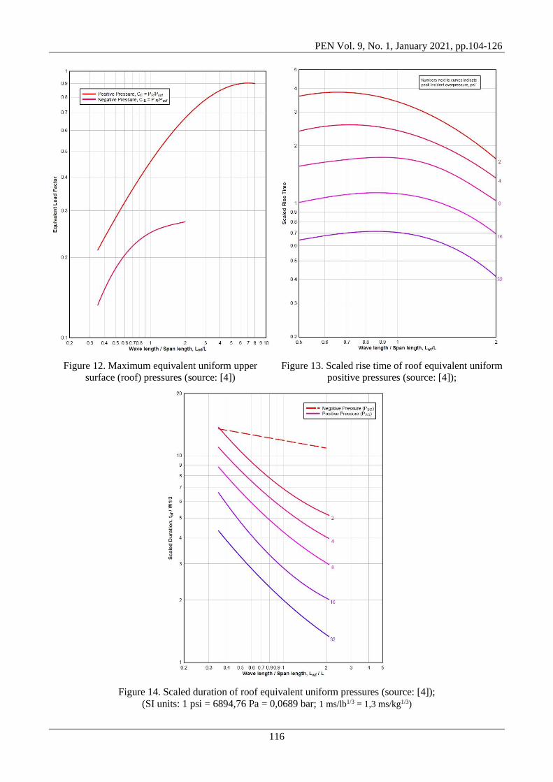
2.2.2 Roof and side walls
When blast wave traverses across the object, the upper (roof) and side walls are pressure loaded (incident
pressure reduced by a negative drag pressure at a given time).
The part of the face loaded at a given time depends generally on the incident pressure, the location of the front
wave and wavelength of positive (Lw) and negative phases (Lw-). To estimate total loading on a surface, one
needs to analyse the wave movement across the face - this requires integration of the pressures at different
locations (Figure 11a), to calculate the equivalent uniform incident pressure on a distance L (Fig. 11b).
Figure 11. Roof and side wall loading (source: [4])
As shown in Fig. 11, the equivalent uniform pressure will rise in a linear fashion from tf, when the shock wave
approaches the front element of a structure (point f), to td, when the maximum equivalent uniform pressure is
obtained. This pressure will after that decrease to zero at location b on the element.
The equivalent load factor CE, the rise time, and duration of equivalent uniform pressure can be obtained from
diagrams in Figures 12, 13, and 14, as a function of ratio Lwf /L.
The maximum pressure PR acting on the roof can be estimated by summation of equivalent uniform and drag
pressure [4]:
ofDsofER qCPCP += (7)
Here Psof represent the incident pressure (at point f), and qof dynamic pressure (corresponding to CEPsof).
Recommended values for CD (for the upper and side walls depend on the maximum dynamic pressure) are
presented in table 3.
Table 3. Recommended CD values (Source: [4,13])
Loaded surface Drag coefficient
Front 0,8 - 1,6
Rear 0,25 - 0,5
Side and roof (pressure dependent)
0 - 172,4 kPa -0.4
172,4 - 344,7 kPa -0.3
344,7 - 896,3 kPa -0.2
For overall motion of an object, the negative phase pressures effects should also be estimated during the
procedure [4].
PEN Vol. 9, No. 1, January 2021, pp.104-126
116
Figure 12. Maximum equivalent uniform upper
surface (roof) pressures (source: [4])
Figure 13. Scaled rise time of roof equivalent uniform
positive pressures (source: [4]);
Figure 14. Scaled duration of roof equivalent uniform pressures (source: [4]);
(SI units: 1 psi = 6894,76 Pa = 0,0689 bar; 1 ms/lb1/3 = 1,3 ms/kg1/3)

PEN Vol. 9, No. 1, January 2021, pp.104-126
117
2.2.3 Rear wall
The shockwave front will expand as the front crosses the rear/back parts of the roof and/or structural side
walls, forming secondary waves moving over the back wall. The secondary wave engulfing the back wall
results from the "spillover" from the roof, and the side walls, in the case of longer structures. These secondary
waves are further strengthened after hitting reflecting surfaces.
In most construction cases, calculating the total drag effects on the building is the key justification for
estimation of the blast loads on the rear wall.
The blast loading on the back wall (Fig. 15a) is estimated using the similar method as the one used for the
blast loads on the upper surfaces (roof) and side walls of the object. Here the maximum pressure of the
equivalent uniform P-t curve (Fig. 15b) is estimated using the maximum pressure Psob that would develop at
the back edge of the upper surface.
The equivalent uniform load factors (CE, CE-) are based on the maximum pressure values. The dynamic
pressure corresponds to the one associated with the equivalent pressure CEPsob, and the drag coefficients
recommendations are the similar as the ones used for the upper surface (roof) and side walls of given
structure. [4].
Figure 15. Rear wall loading (source: [4])
An examples of (manual) calculations of external load on structures and construction of approximate P(t)
diagrams can be found in [4,8,10].
2.3. Influence of openings in the structure
To ensure sufficient light and ventilation, modern buildings contain wide gaps, typically on either side.
Windows are the first components of the system that are expected to collapse when a blast wave reaches a
structure. The prevailing theory of structural architecture allows them to be the weakest component of the
structure, even though they are built to retain those pressure values, so failure of the wall before failure of the
glass facade is naturally more risky.
When in contact with a standard window, the blast wave front automatically causes its collapse and it spreads
inside the object. Around the same time, as some energy is consumed by the glass breakage [8], the maximum
value of the overpressure wave will eventually become lower.

PEN Vol. 9, No. 1, January 2021, pp.104-126
118
When blast loads are calculated on buildings with exposed openings on external faces, two structural
configurations are commonly encountered. Windows, light doors or different openings situated in both the
front and upper (roof) walls and along the structure's side walls are part of the first configuration. The second
configuration encompasses openings found in the structure's front face only, and the other surfaces typically
don’t have openings.
When a shock wave front attacks a structure's front wall, the incident pressure is intensified. Windows and
doors collapse almost instantly, unless they are designed to withstand the load. As a consequence, through
these holes, blast wave fill the object. This abrupt release of high pressure will cause the inside of each
opening to form a new shock wave front.
Each independent front will extend and appear to converge into a single wave front that expanding in the
interior of the object. This internal shock is initially lower than the incident pressure of the wave on the
outside of the structure but because of reflections, the interior pressure would eventually get larger.
In Fig. 16, an idealized structural object is presented. The arriving shock front has incident pressure Pso and
wave length Lw. Blast wave penetrate the interior of the structure from the hole (opening) in the front part
(with area A0), as the shock front goes through the object. To achieve a hypothetical single opening centred at
the middle of the front wall, the multiple openings area is usually determined (by summation of individual
ones) [4].
Figure 16. Idealized structure scheme for interior blast loads (source: [4])
Fig. 17 further illustrates the idealized P-t load curves for these (internal) surfaces inside a structure. The blast
pressures operating on the outside of the building in residential area, except for the front wall, are not
influenced by the opening in the object, and are calculated in compliance with the procedures mentioned in
the preceding section.

PEN Vol. 9, No. 1, January 2021, pp.104-126
119
Figure 17. Idealized interior blast loads (source: [4])
As an example of software application for these cases, the CHAMBER code was developed to compute the
pressure in a rectangular box-shaped room (structure) produced by the air blast from external explosions
penetrating into the room through openings in the walls such as doors, windows and ducts of air entrainment
systems [9].
3. Structural response to blast loading
When a shock wave hits an object, it generates a dynamic response, caused by the pressure and impulse
transferred to the object [21].
The rate at which the impulse builds up is important since it can determine the strain rate of the target [22].
Blast load events induce large strain rates, approximately 102 - 104 s−1 [23]. The strength of structures is not
only dependent on the load but also on structure characteristics, such as its geometry and materials. An object
hit by a blast wave experiences a loading action which may cause deformation, and different damage levels
can occur if the stresses and strains exceed those that the material can tolerate [9].
The deformation can take place in the entire structure when a blast wave hits the target, or can be built up in
the central part, in the case of a localised blast wave, so the deflection response is dependent on the blast
loading area. The magnitude and spatial distribution of blast loads on a given structure depends on several
factors: characteristics of high-explosive materials, the stand-off distance, target or surroundings, and the
amplification of the pressure pulse due to the reflection [24].
The natural period T of an object play an important role on its response [8]. Generally, three load regimes can
be defined: impulsive, dynamic and quasi-static. The impulsive regime is present when the load pulse is short
compared to the structure natural period of vibration: 4,00 t , where (= 2/T) is natural vibration
frequency of an object. The dynamic regime occurs when the load duration and structural response times have
similar order of magnitude: 404,0 0 t . The quasi-static regime applies when the load duration is long
compared to the structure natural response: 400 t . For impulsive loading, most of the deformation will
occur after the blast load ended, and for quasi-static loading the blast will cause deformation of the structure
while the loading is active [16].
The so called pressure - impulse (P-I) diagrams are used to define the limits for a safe response of structural
member under different loading. Although these have been generally applied to predict structural damage,
they can also be successfully used to predict human injuries due to the blast [16]. An example of a P-I
diagram used frequently in blast analysis is shown in Figure 18, where the boundary contour line for a specific
damage level is present [20].

PEN Vol. 9, No. 1, January 2021, pp.104-126
120
Figure 18. Typical pressure-impulse diagram (source: [20])
Diagram in Fig. 18 shows all the pressure - impulse combinations that generate the same damage level in a
system. P-I diagrams are a representation of so called iso-damage curves [20].
There are two distinct regions in a pressure - impulse diagram (Fig. 18): significant structural damage and
minor or no damage. P-I combinations to the left side and below given contour show responses below the
corresponding damage level, and those above and to the right side of the contour will produce responses
above the damage limit. For impulsive loads, the structural response is not dependent on the pressure.
The associated impulse is, however, the main parameter influencing the behaviour of the structure. For quasi-
static loads the response depends on the pressure but on the impulse. The quasi-static asymptote is defined by
the minimum pressure needed to reach a specific damage level. In between is a dynamic regime, which
connects the impulsive asymptote with the quasi-static asymptote, and where the structural response depends
on both pressure and impulse [20].
Designing structures to resist explosion blast waves is a very complex, and the evaluation of the structural
strength under blast loads through computer simulations uses mainly two methods [20]:
− Computational Fluid Dynamics (CFD) which allows the study of interactions between a fluid and a
solid structure (Fluid-Solid Interaction),
− Computational Solid Mechanics (CSM), dealing with response of the structure.
4. Numerical simulations
The empirical method outlined in the previous section permits estimation of explosive shock wave effects
mostly for isolated structures. Structure complex geometry, other structures in proximity, and the surrounding
environment cannot be taken into account using exclusively these methods. Also, the simplified empirical
techniques give relatively good agreement with the test data only for the structure sides situated on the front
surface. To overcome these limitations, various CFD (eng. Computational Fluid Dynamics) methods and
Hydrocodes (large computer programs used to numerically simulate dynamic events, particularly those which
include shocks) are used for prediction of blast load on the objects. [18].
Numerical simulations in this paper were performed in Ansys AUTODYN program.

PEN Vol. 9, No. 1, January 2021, pp.104-126
121
When simulating explosions, material properties can be selected from the AUTODYN material library. Air
uses the equation of state for Ideal gas, where the pressure P is related to the energy e (with adiabatic
exponent ) [25] as:
( ) eP 1−=
(8)
This form of an equation is useful for its simplicity and computation ease, where only the value of needs to
be supplied.
For high explosives (ie TNT), there are different forms of equations of state (Ideal gas, Constant Beta,
Wilkins, Becker-Kistiakowski-Wilson), but the one used in AUTODYN is Jones - Wilkins - Lee (JWL), in the
following form [25]:
v
ee
vRBe
vRAp
vrvr +
−+
−=
−− 21
21
11 (9)
The values of A, R1, B, R2, and constants from Eq. (9) have been determined from dynamic experiments (i.e.
cylinder test) for many explosive types, and are available in AUTODYN material library.
In this research, as a validation of the AUTODYN program method for solving urban blast problems, we
numerically simulated blast wave formation in a 3D urban scene (Fig. 19) and compared obtained results to
the ones experimentally studied in reference [15].
Seven buildings of different heights (Fig. 19) simulated the cityscape. The experiment [1] used scaled urban
scenarios where buildings B1, B2, and B4 were 400 mm high, buildings B3 and B5 300 mm high, and
buildings RW and LW 450 mm high. The TNT charge with a mass of 16 g (charge radius of 13,28 mm), and
a density of 1630 kg/m3, was detonated at the point located 40mm above the ground between buildings. In
relation to the origin coordinate system, the detonation point was located at following coordinates: 478 mm,
350 mm, 40 mm. Pressure measuring (gauge) point was located at following coordinates: 302 mm, 1100 mm,
105 mm.
Figure 19. Initial setup of an urban environment explosion scenario (adapted from [1])
To numerically simulate the experiment [1] with an urban blast, a 3D numerical simulation was required. As a
first step we used CAD (Computer-Aided Design) software to make a 3D model of the buildings, export the
model as .iges universal document type, and imported it into Ansys Workbench (this can also be done in
Ansys Geometry Modeler). In this way, one can import any urban area CAD model available.

PEN Vol. 9, No. 1, January 2021, pp.104-126
122
The next step was to do a 2D axisymmetric numerical simulation of free airblast in AUTODYN, with given
explosive charge geometry (13,28 mm radius). Mesh cells were 1 mm in size.
Values for different materials equations of state, as well as other material parameters, were specified from the
default AUTODYN material library. Zones with air were defined with energy of 2,068105 mJ/mm3 (to obtain
an environmental pressure of 101,3 kPa) - initial condition. Results of this simulation were saved and later
remapped into an urban environment (remap origin coordinates were chosen as in experiment [1], Fig. 19) in
3D AUTODYN. Next we specified coordinate system origin and initial conditions in Ansys Workbench (earth
gravity, and fixed, rigid buildings), and exported files into AUTODYN where the following procedure was
used:
• Loading of air and TNT as materials (with default parameter values from AUTODYN material
library).
• Specifying the initial condition (air was given initial energy of 2,068105 mJ/mm3).
• The flowout boundary condition was specified to eliminate the wave reflection at the end of spatial
domain.
• Rectangular space grid was specified around buildings, and filled with air. Two Euler solvers were
used (separately): Euler - Godunov and Euler - FCT, for the comparation of the results.
• With Euler - Godunov solver we conducted simulations with two mesh cell sizes, 20 mm (336175
cells) and 10 mm (2768500 cells), to conduct a mesh independence study. With Euler - FCT solver
we conducted all simulations with cell size of 10 mm (total 2768500 cells), but with two different
quadratic viscosities (1 and 0,1), since reference [26] suggest values of 0,1 as more accurate.
• Remapping of earlier 2D simulation results into 3D AUTODYN urban environment (coordinate point
for detonation was specified as in the experiment, Fig. 19).
• Specifying gauge point location as in the experiment.
• Specifying simulation end time of 5 s (enough time for a pressure wave to engulf the structures).
• Specifying parallel processing method. Simulation run time (for 5s of simulation) with 2768500 cells
was around 7h using octa-core processor (AMD Ryzen 7).
Fig. 20 shows pressure profiles determined with Euler solvers, compared (validated) to test data [1]. All
solvers predict the event adequately, but FCT solver generally agrees better with test data, a conclusion also
confirmed in [18]. Regarding mesh independence, there were no large qualitative differences in results
between curves obtained with 10 mm and 20 mm cell sizes (see Euler - Godunov curves in Fig. 20), but
smaller mesh size grid does give better prediction of the peak pressure. Regarding quadratic viscosities, values
of 0,1 agree somewhat better with test data than the values of 1, a conclusion confirmed also in [26].
Figure 20. Pressures profiles determined with Euler solvers, compared to experimental data [1]

PEN Vol. 9, No. 1, January 2021, pp.104-126
123
Fig. 21 presents pressure contours for different simulation times, showing wave reflections, diffraction around
corners, and wave channeling due to the urban environment structures.
For the pressure contours section plane (Fig. 21) we selected height of 13,6 mm above ground (average human
height level) since, for the mentioned scaled experiment [1], buildings had an average height of 400 mm.
Namely, if we assume these buildings were in reality around 50 m high, then the value of 13,6 mm (for a
horizontal section plane) in a simulation would correspond roughly to an average human height of 1,75 m in
real case scenario.
Figure 21. Pressure contours for different simulation times
Fig. 22 presents shockwave velocity vectors for different numerical simulation times. Here, the view is
isometric and shows adequately the 3D model of buildings in AUTODYN. In Fig. 22 we can see the
movement of the shockwave and its velocity at different times. Also, wave reflections and superposition can
be seen as a wave develops further away from the detonation point. The last sequence in Fig. 22 shows that
shockwave reaches the furthest buildings in this (scaled) urban model in about 2,25 ms.

PEN Vol. 9, No. 1, January 2021, pp.104-126
124
Figure 22. Velocity vectors for different simulation times
Fig. 23 shows temperature profile, determined with Euler - FCT solver, for test gauge (measuring point) T1
(shown schematically in Fig. 19). We see that the profile is similar as in the case for pressure, with maximum
values for temperature of around 393 K (120 C).
Fig. 24 presents temperature contours for different simulation times. Note that the scales in contours,
presented in Fig. 24, are not the same in different time sequence.
Here, as in the Fig. 21, temperature contours section plane had height of 13,6 mm above ground, which
correspond to an average human height of 1,75 m in real case scenario.
As can be seen from Fig. 24, the temperature quickly decreases as time progresses, and the closest buildings
are impacted the most.

PEN Vol. 9, No. 1, January 2021, pp.104-126
125
Figure 23. Temperature profiles at gauge point T1 (gauge is shown in Fig. 19)
Figure 24. Temperature contours for different simulation times
Analysis of blast wave effects for complex geometry urban scenario is becoming an increasingly relevant
topic since the number of terrorist attacks, and also accidents with explosive material are not decreasing.
Further research could be directed towards interior blast scenario. Also, work could be directed to using GIS
files in a populated environment blast simulation, as a method for estimation of explosion effect in a real case
scenario for certain urban areas. Methods for reinforcing the structures to the blast load could also be pursued
in future research.

PEN Vol. 9, No. 1, January 2021, pp.104-126
126
5. Conclusion
A review of external blast loads on structures modeling methods is presented in the paper. Numerical
simulations of explosion in an urban scenario were done in software Ansys AUTODYN, and results compared
to experimental values. Recommendations were given regarding the use of numerical simulations in blast
wave parameter calculations for the urban environment.
Further research could be directed towards interior blast scenario. Also, work could be directed to using GIS
files in a populated environment blast simulation, as a method for estimation of explosion effect in a real case
scenario for certain urban areas. Methods for reinforcing the structures to the blast load could also be pursued
in future research.
References
[1] M. A. Brittle, Blast propagation in a geometrically complex environment, Thesis, Craneld University, Defence
College of Management and Technology, Shrivenham, Swindon, SN6 8LA, UK, July 2004.
[2] Military explosives, US Army Technical Manual, TM 9-1300-214, Sept. 1984.
[3] "Explosive weapon effects", GICHD, Geneva, ISBN: 978-2-940369-61-4, February 2017.
[4] UFC 3-340-02, Structures To Resist The Effects Of Accidental Explosions, Technical manual, Dec. 2008.
[5] Engineering Design handbook. Explosions in Air. Part One, Army Materiel Command, Alexandria, Virginia, 15
July 1974.
[6] M. L. Costa Neto, G. N. Doz, "Study of blast wave overpressures using the computational fluid dynamics",
Rev. IBRACON Estrut. Mater. vol.10 no.3 São Paulo, May/June 2017.
[7] A. M. Remenikov, "The state of the art of explosive loads characterisation", Journal Of Battlefield Technology,
Vol 6, No 3, 2003.
[8] V. Karlos, G. Solomos, "Calculation of Blast Loads for Application to Structural Components", Joint Research
Center, 2013.
[9] P. D. Smith, J. G. Hetherington, Blast and Ballistic Loading of Structures, Butterworth-Heinemann Ltd 1994.
[10] A. M. Remenikov, "Blast Resistant Consulting: A New Challenge for Structural Engineers", Australian
Journal of Structural Engineering · January 2002.
[11] "Improvised Explosive Devices (IEDs) - Publication", UN, Office for Dissarmament Affairs,
https://www.un.org/disarmament/convarms/ieds2/.
[12] P. S. Bulson, Explosive Loading of Engineering Structures, Chapman and Hall, 1997.
[13] H. Draganic, V. Sigmund, "Blast loading on structures", Tehnički vjesnik 19, 3(2012), 643-652.
[14] S. E. Rigby, T. J. Lodge, S. Alotaibi, A. D. Barr, S. D. Clarke, G. S. Langdon, A. Tyas, "Preliminary yield
estimation of the 2020 Beirut explosion using video footage from social media". Shock Waves.
doi:10.1007/s00193-020-00970-z. ISSN 1432-2153.
[15] AUTODYN®, Material library, Ansys Inc, 2019.
[16] D. Cormie, G. Mays, P. Smith, Blast effects on buildings, Second edition, Thomas Telford Publications, 2009.
[17] N. Birnbaum, R. Clegg, G. Fairlie, C. Hayhurst, N. Francis, "Analysis of blast loads on buildings", Structures
under Extreme Loading Conditions, 1996.
[18] N. N. Fedorova, S. A. Valger, A. V. Fedorov, "Simulation of blast action on civil structures using Ansys
AUTODYN", International Conference on the Methods of Aerophysical Research (ICMAR 2016), AIP Conf.
Proc. 1770, 020016-1–020016-10; doi: 10.1063/1.4963939.
[19] W. E. Baker, P. A. Cox, P. S. Westine, J. J. Kulesz, R. A. Strehlow, Explosion Hazards and Evaluation.
Elsevier, 1983.
[20] A. Cacoilo, "Blast wave propagation in confined spaces and its action on structures", PhD Thesis, The
University of Edinburgh, 2019.
[21] C. E. Needham, Blast waves, Second Edition, Springer, 2018.
[22] A. Wright, M. French, "The response of carbon fibre composites to blast loading via the Europa CAFV
programme", Journal of Materials Science, 43(20):6619–6629, 2008. ISSN 0022-2461, 1573-4803. doi:
10.1007/s10853-008-2787-7.
[23] T. Ngo, P. Mendis, A. Gupta, J. Ramsay, "Blast loading and blast effects on structures - an overview",
Electronic Journal of Structural Engineering, 2007.
[24] F.E.M.A. Reference manual to mitigate potential terrorist attacks against buildings. Technical Report FEMA
426, Department of Homeland Security, US, 2003.
[25] AUTODYN®, Explicit Software for Nonlinear Dynamics, Theory Manual Revision 4.3, 2005. [26] T. C. Chapman, T. A Rose, P. D. Smith, "Blast wave simulation using AUTODYN2D: A parametric study",
Int. J. Impact Engng, Vol 16, No 5/6, pp. 777-787, 1995.