Embed Size (px)
Citation preview

Review of the
7 June 2008 Landslide Cluster
on the Natural Hillside
above Tai O San Tsuen,
Tai O, Lantau Island
GEO Report No. 275
AECOM Asia Company Limited
Geotechnical Engineering Office
Civil Engineering and Development Department
The Government of the Hong Kong
Special Administrative Region

Review of the
7 June 2008 Landslide Cluster
on the Natural Hillside
above Tai O San Tsuen,
Tai O, Lantau Island
GEO Report No. 275
AECOM Asia Company Limited
This report was originally produced in August 2011
as GEO Landslide Study Report No. LSR 3/2011

2
© The Government of the Hong Kong Special Administrative Region First published, February 2013 Prepared by: Geotechnical Engineering Office, Civil Engineering and Development Department, Civil Engineering and Development Building, 101 Princess Margaret Road, Homantin, Kowloon, Hong Kong.

3
Preface
In keeping with our policy of releasing information which may be of general interest to the geotechnical profession and the public, we make available selected internal reports in a series of publications termed the GEO Report series. The GEO Reports can be downloaded from the website of the Civil Engineering and Development Department (http://www.cedd.gov.hk) on the Internet. Printed copies are also available for some GEO Reports. For printed copies, a charge is made to cover the cost of printing. The Geotechnical Engineering Office also produces documents specifically for publication in print. These include guidance documents and results of comprehensive reviews. They can also be downloaded from the above website. The publications and the printed GEO Reports may be obtained from the Government’s Information Services Department. Information on how to purchase these documents is given on the second last page of this report. H.N. Wong
Head, Geotechnical Engineering Office February 2013

4
Foreword This report presents the findings of a review of a landslide cluster that occurred on the natural hillside above Tai O San Tsuen, Tai O, Lantau Island. The landslides were reported on the morning of 7 June 2008 following very heavy rainfall. The incident involved five separate landslide areas, some with multiple sources. The total failure volume involved was about 1000 m³. Much of the debris was deposited at the toe of the hillside with a small proportion remained on the hillside. No casualties were reported as a result of the landslides. The key objectives of this review were to document the facts about the landslides, including relevant background information and pertinent site observations made under this review. The scope of the review does not include detailed diagnosis of the causes of the incident. Recommendations for follow-up actions are reported separately.
The report was prepared for the Geotechnical Engineering Office of the Civil Engineering and Development Department, under Agreement No. CE 41/2007 (GE). This is one of a series of reports produced during the consultancy by AECOM Asia Company Limited.
Fred H Y Ng Project Director
AECOM Asia Company Limited
Agreement No. CE 41/2007 (GE) Study of Landslides Occurring in Kowloon
and the New Territories in 2008 – 2009

5
Contents
Page No. Title Page 1
Preface 3 Foreword 4
Contents 5
List of Tables 6
List of Figures 7 1 Introduction 9 2 The Site 9 3 The 7 June 2008 Landslides 10 4 Site History and Past Instability 12 5 Post-failure Observations 15 6 Geology and Geomorphology 22
6.1 Geology 22
6.2 Geomorphology 26 7 Analysis of Rainfall Records 26 8 Discussion 31 9 Conclusion 31 10 References 32 Appendix A: Aerial Photograph Interpretation 33 Appendix B: Previous Engineer Inspection and Routine Maintenance 43 Inspection Appendix C: Detailed Observations of the Landslides 46

6
List of Tables
Table No.
Page No.
5.1 Summary of the Landslide Cluster
15
7.1 Maximum Rolling Rainfall at GEO Raingauge No. N19 for Selected Durations Preceding the 7 June 2008 Landslide and the Estimated Return Periods
27

7
List of Figures
Figure No.
Page No.
1.1
Location Plan 9
2.1 General View of the 7 June 2008 Landslides from Helifight (Photograph Taken in June 2008)
10
2.2 Site Layout Plan and Utilities
11
4.1 Site History and Previous Ground Investigation Plan
13
4.2 Past Instabilities
14
5.1 Site Geomorphology and Hydrology
16
5.2 Slope Angle Distribution Plan
17
5.3 View of the Southern Flank at Source Area LS2e (Colluvium Overlying Partially Weathered Rock Mass) (Photograph Taken on 19 June 2008)
18
5.4 View of Landslide No. LS1 (Photograph Taken on 13 June 2008)
18
5.5 View of the Source Area of Landslide No. LS5 (Photograph Taken on 13 June 2008)
19
5.6 General View of Landslide No. LS3 (Photograph Taken on 13 June 2008)
19
5.7 Tension Crack on North Flank of Main Scarp of Source Area LS2a (Photograph Taken on 19 June 2008)
20
5.8 Tension Crack within Source Area LS4b (Photograph Taken on 19 June 2008)
21
5.9 Tension Crack above Main Scarp at Source Area LS4b (Photograph Taken on 19 June 2008)
21
6.1 Regional Geology
23
6.2 Moderately Decomposed Tuff showing Dilation and Infills along Joint within the Source Area LS2c (Photograph Taken on 15 June 2008)
24

8
Figure No.
Page No.
6.3 Geological Section A-A through Landslide No. LS1
24
6.4 Geological Section B-B through Landslide No. LS2
25
6.5 Geological Section C-C through Landslide No. LS3
25
7.1 Daily and Hourly Rainfall Recorded at GEO Raingauge No. N19
28
7.2 Maximum Rolling Rainfall for Previous Major Rainstorms at GEO Raingauge No. N19
29
7.3 Location and Directions of Photograph Taken
30
9
1 Introduction
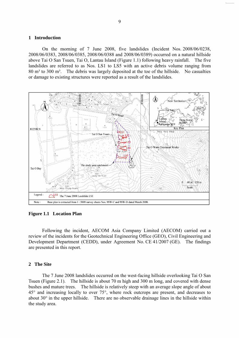
On the morning of 7 June 2008, five landslides (Incident Nos. 2008/06/0238, 2008/06/0383, 2008/06/0385, 2008/06/0388 and 2008/06/0389) occurred on a natural hillside above Tai O San Tsuen, Tai O, Lantau Island (Figure 1.1) following heavy rainfall. The five landslides are referred to as Nos. LS1 to LS5 with an active debris volume ranging from 80 m³ to 300 m³. The debris was largely deposited at the toe of the hillside. No casualties or damage to existing structures were reported as a result of the landslides.
Figure 1.1 Location Plan
Following the incident, AECOM Asia Company Limited (AECOM) carried out a review of the incidents for the Geotechnical Engineering Office (GEO), Civil Engineering and Development Department (CEDD), under Agreement No. CE 41/2007 (GE). The findings are presented in this report. 2 The Site
The 7 June 2008 landslides occurred on the west-facing hillside overlooking Tai O San Tsuen (Figure 2.1). The hillside is about 70 m high and 300 m long, and covered with dense bushes and mature trees. The hillside is relatively steep with an average slope angle of about 45° and increasing locally to over 75°, where rock outcrops are present, and decreases to about 30° in the upper hillside. There are no observable drainage lines in the hillside within the study area.

10
Figure 2.1 General View of the 7 June 2008 Landslides from Helifight
(Photograph Taken in June 2008)
Several registered cut slopes are located at the toe of the hillside (Figure 2.2), in front
of which are village houses and a Tin Hau Temple. Further away from the hillside toe are abandoned cultivation areas and ponds. An unpaved footpath traverses the mid-slope of the subject hillside and a paved footpath runs along the ridgeline.
The Water Services Department‟s (WSD) Tai O Water Treatment Works is located at
the crest of the southern part of the hillside, about 30 m to the southeast of landslide No. LS5. According to information provided by the WSD, an 80 mm diameter ductile iron
sludge pipe runs along the ridge from the WSD Water Treatment Works (Figure 2.2). There was no reported leakage from the sludge pipe in the vicinity prior to the June 2008 incident.
3 The 7 June 2008 Landslides
The landslides occurred in the early morning of 7 June 2008 according to residents of
Tai O San Tsuen. Landslide Nos. LS1, LS3 and LS5 involved a single source area, whereas landslide Nos. LS2 comprised 5 source areas (namely LS2a to LS2e) and landslide No. LS4 comprised 2 source areas (namely LS4a and LS4b) (Figure 2.2). The active debris volume ranged between 80 m³ from landslide No. LS1 and 300 m³ from landslide No. LS2.
LS1
LS3 LS5
Tai O San Tsuen
LS2
LS4
The Study Area

11
Figure 2.2 Site Layout Plan and Utilities

12
The landslide debris was mainly deposited on the open space at the toe of the hillside. Some debris came to rest against the rear of the village houses and Tin Hau temple at the toe of the hillside, while a small proportion of debris travelled further and reached the footpath in front of the village houses and the ponds beyond. The runout distance of the debris was up to about 80 m.
4 Site History and Past Instability
The history of the study area has been determined from an interpretation of the
available aerial photographs, together with a review of relevant documentary information (Figures 4.1 & 4.2). Detailed observations from the aerial photograph interpretation (API) are presented in Appendix A.
The study area is located on a west-facing natural hillside, formerly a coastal hillside
now protected by alluvial plains extending in front. The hillside would have undergone active coastal erosion processes over time, as reflected by the presence of numerous historical landslide occurrence in the area (Figure 4.2).
To the west of the study area is a flat low-lying alluvial and estuarine area previously
comprising extensive cultivation lands, salt fields and isolated village houses. Several cut slopes located below landslide Nos. LS1 to LS4 were formed by cutting into the toe of the natural hillside during the development of Tai O San Tsuen between 1963 and 1981 (Figure 4.1).
The first construction phase of Tai O Water Treatment Works, about 30 m to the
southeast of landslide No. LS5, was completed in 1974. Further site formation works were completed in around 1981 and 2001 in phases.
The study area has a history of landslides. In the 1963 aerial photographs, ten relict
landslides (namely R1 to R10) are identified (Figure 4.2). Between 1963 and 1969, a possible area of local instability or an excavation was observed near the toe of landslide LS2 (Figure 4.1). Between 1969 and 1990, four recent landslides (namely RL1 to RL4) are visible within the study area (Figure 4.2). According to the GEO‟s Large Landslide database (Scott Wilson, 1999), there is one large landslide in the vicinity of landslide No. LS4 (Figure 4.2).
The previous landslides recorded within the study area are predominantly open
hillslope landslides, many of which are located at or close to the 7 June 2008 landslides (Figure 4.2). The scale of previous landslides is similar to that of the 7 June 2008 landslides, typically at about 50 m3 to 150 m3.
In 1999, Engineer Inspection identified a minor failure with an estimated failure
volume less than 50 m3 at slope No. 9SW-D/C199 (Figure 4.2 & Appendix B). The failure was probably due to erosion, and was located about 10 m south to landslide No. LS1.
Except for landslide No. LS5, the June 2008 failures are all located within Historical
Landslide Catchments (Figure 4.2).

13
Figure 4.1 Site History and Previous Ground Investigation Plan

14
Figure 4.2 Past Instabilities

15
5 Post-failure Observations
Following the 7 June 2008 landslides, the first inspection conducted by AECOM was
on 13 June 2008, and subsequently on 15 and 19 June 2008. Key observations for each landslide are summarized in Table 5.1 and Appendix C.
The landslide source areas were located within the upper hillside above the convex break-in-slope (Figure 5.1). The hillside concerned is relatively steep with a slope angle predominantly ranging from about 30º to over 45º (Figure 5.2). The dimensions (i.e. width x length) of the source areas ranged from 4 m x 8 m (at landslide No. LS2) to 14 m x 15 m (at landslide No. LS5). The failure was shallow with a maximum depth of about 2 m. The source volumes ranged from 25 m3 to 160 m3.
Table 5.1 Summary of the Landslide Cluster
Landslide No.
Single (S) / Multiple
(M) Sources
Source Area (for Multiple
Sources)
Pre-failure Slope
Gradient at Source (°)
Source Width (m)
Source Length
(m)
Source Depth (m)
Source Volume
(m3)
Entrainment Volume
(m3)
Deposition Volume**
(m3)
Mass Balance
(m3)
Runout Distance#
(m)
Elevation Difference between
Landslide Crown and Distal End of Debris
(m)
Travel Angle
(°)
LS1 S - 32 10 12 1.5 80 0 0 80 21 15 35
LS2 M
LS2a 30 6 11 1.5 75
50
50
300 68*
48 -
LS2b 29 4 8 1.5 25 0 43 -
LS2c 46 4 8 1 50 0 35 -
LS2d 38 10 13 0.5 50 0 17 -
LS2e 39 6 17 1.5-2 100 0 36 -
LS3 S - 32 7 18 1.5 130 40 25 145 63* 50 -
LS4 M LS4a 42 4 13 1.5 75
70 40
185 75 50
34^ LS4b 31 6 12 1.5 80 0 53
LS5 S - 35 14 15 1 160 40 0 200 80 53 34
Total 825 200 115 910
Notes: (1) LS1 to LS5 are all open hillslope landslides. (2) # Runout distance based on the highest elevation source area. (3) * Most of the debris came to rest up against the village structures at the
base of the slope. (4) ** Deposition volume - total debris deposited within the source area and
along the trail. (5) ^ Travel angle based on the minimum elevation difference between
landslide crown and distal end of debris.

16
Figure 5.1 Site Geomorphology and Hydrology

17
Figure 5.2 Slope Angle Distribution Plan

18
The material exposed on the surface of rupture typically comprised partially weathered rock mass (PW30/50 to 90/100) with a thin layer of colluvium (Figures 5.3, 5.4 & 5.5). The weathered rock mass is generally dilated with some open and sediment infilled joints as observed at some source areas (Figure 6.2). The orientation of the joints was generally not adverse. However, a joint set striking sub-parallel out of the slope was observed at the basal rupture surface of landslide No. LS3 (Figure 5.6).
Figure 5.3 View of the Southern Flank at Source Area LS2e (Colluvium Overlying
Partially Weathered Rock Mass) (Photograph Taken on 19 June 2008)
Colluvium
Partially weathered rock mass PW50/90
Partially weathered rock mass PW 30/50
Exposed relict joints forming part of surface of rupture
Figure 5.4 View of Landslide No. LS1 (Photograph Taken on 13 June 2008)
House No. 4
Colluvium
PW 50/90 rock mass
PW 90/100 rock mass
Main scarp
Source floor

19
Figure 5.5 View of the Source Area of Landslide No. LS5 (Photograph Taken on
13 June 2008)
Figure 5.6 General View of Landslide No. LS3 (Photograph Taken on 13 June 2008)
Dilated rock mass
Joint set sub-parallel to slope profile
Source floor mainly comprised PW 50/90 and PW 90/100 rock
mass
Colluvium
PW 30/50
0.5 m
1 m
Right flank

20
Signs of seepage, soil pipes or other adverse hydrogeological conditions were not observed within the source areas during the inspections, which were conducted several days after the incident.
Several tension cracks were observed adjacent to the source areas of landslides
Nos. LS2 to LS5 (Figures 2.2, 5.7, 5.8 & 5.9). These cracks were up to about 5 m long with a vertical displacement of 0.5 m and probably extended into the weathered rock mass. The presence of tension cracks, together with the open joints in weathered rock mass, suggests that the hillside may have been undergoing deterioration.
Figure 5.7 Tension Crack on North Flank of Main Scarp of Source Area LS2a
(Photograph Taken on 19 June 2008) The hillside undulates in transverse profile with some broad, rounded linear
depressions. Some entrainment (less than 70 m3) was evident from landslides Nos. LS 2 to LS5, where the debris travelled along areas of topographic depressions in the hillside. The active debris volume for landslide Nos. LS1 to LS5 ranged from 80 m³ to 300 m³, taking into account the material entrained. Local topographic depressions are present around the source areas.
1 m
0.5 m

21
Figure 5.8 Tension Crack within Source Area LS4b (Photograph Taken on
19 June 2008)
Figure 5.9 Tension Crack above Main Scarp at Source Area LS4b (Photograph Taken
on 19 June 2008)
0.8 m
22
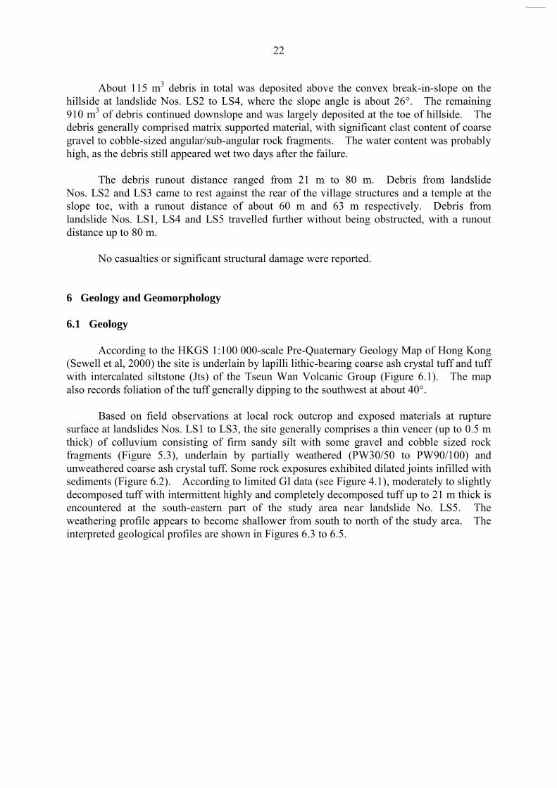
About 115 m3 debris in total was deposited above the convex break-in-slope on the hillside at landslide Nos. LS2 to LS4, where the slope angle is about 26°. The remaining 910 m3 of debris continued downslope and was largely deposited at the toe of hillside. The debris generally comprised matrix supported material, with significant clast content of coarse gravel to cobble-sized angular/sub-angular rock fragments. The water content was probably high, as the debris still appeared wet two days after the failure.
The debris runout distance ranged from 21 m to 80 m. Debris from landslide
Nos. LS2 and LS3 came to rest against the rear of the village structures and a temple at the slope toe, with a runout distance of about 60 m and 63 m respectively. Debris from landslide Nos. LS1, LS4 and LS5 travelled further without being obstructed, with a runout distance up to 80 m.
No casualties or significant structural damage were reported.
6 Geology and Geomorphology
6.1 Geology
According to the HKGS 1:100 000-scale Pre-Quaternary Geology Map of Hong Kong
(Sewell et al, 2000) the site is underlain by lapilli lithic-bearing coarse ash crystal tuff and tuff with intercalated siltstone (Jts) of the Tseun Wan Volcanic Group (Figure 6.1). The map also records foliation of the tuff generally dipping to the southwest at about 40°.
Based on field observations at local rock outcrop and exposed materials at rupture
surface at landslides Nos. LS1 to LS3, the site generally comprises a thin veneer (up to 0.5 m thick) of colluvium consisting of firm sandy silt with some gravel and cobble sized rock fragments (Figure 5.3), underlain by partially weathered (PW30/50 to PW90/100) and unweathered coarse ash crystal tuff. Some rock exposures exhibited dilated joints infilled with sediments (Figure 6.2). According to limited GI data (see Figure 4.1), moderately to slightly decomposed tuff with intermittent highly and completely decomposed tuff up to 21 m thick is encountered at the south-eastern part of the study area near landslide No. LS5. The weathering profile appears to become shallower from south to north of the study area. The interpreted geological profiles are shown in Figures 6.3 to 6.5.

23
Figure 6.1 Regional Geology

24
Figure 6.2 Moderately Decomposed Tuff showing Dilation and Infills along Joint within
the Source Area LS2c (Photograph Taken on 15 June 2008)
Dilated rock mass with weaker materials
along joint Partially weathered
rock mass PW 50/90
Partially weathered rock mass PW 90/100
Joints/relict joint surfaces within partially weathered
rock mass forming the surface of rupture
Figure 6.3 Geological Section A-A through Landslide No. LS1

25
Figure 6.4 Geological Section B-B through Landslide No. LS2
Figure 6.5 Geological Section C-C through Landslide No. LS3

26
6.2 Geomorphology
The June 2008 landslides occurred on the western flank of a north-south trending ridgeline with a history of landslides. The ridgeline forms a small hillside ‘peninsula’ extending northwards into the surrounding coastal/estuarine embayment. The hillside is generally inclined at about 30° to 45° in the upper part, where most of the 7 June 2008 landslides occurred (Figures 5.1 & 5.2). In the middle hillside areas, there are distinct breaks in slope where the gradient increases to between 45° and 75°, below which the remaining June 2008 landslide source areas are located.
No perennial or ephemeral streams are observed on the hillside, although several
topographic depressions may have been present, in particular near landslide Nos. LS4 and LS5 (Figure 2.2). 7 Analysis of Rainfall Records
Rainfall data were obtained from the nearest GEO automatic raingauge No. N19, which is located about 1.5 km to the southeast of the 7 June 2008 landslides at Tai O San Tsuen. The raingauge records and transmits rainfall data at 5-minute intervals to the GEO and the Hong Kong Observatory (HKO). The daily rainfall recorded by raingauge No. N19 over the month preceding the 7 June 2008 rainstorms, together with the hourly rainfall readings for the period between 5 and 7 June 2008, are presented in Figure 7.1.
The Black Rainstorm Warning was issued on 7 June 2008 between 6:40 a.m. and
11:00 a.m. The rainstorm started at about midnight on 6 June 2008 and the maximum 1-hour rolling rainfall at raingauge No. N19 was 99.5 mm, which was recorded between 6:00 a.m. and 7:00 a.m. on 7 June 2008 (Table 7.1).
According to the residents in the area, the landslides occurred in the early morning of
7 June 2008. The time of occurrence of the landslide was assumed to be 7:00 a.m. in the GEO landslide record. For the purpose of this rainfall analysis, the landslides were also assumed to have occurred at 7:00 a.m. on 7 June 2008.
An estimation of the return periods for various durations of maximum rolling rainfall
recorded by raingauge No. N19 was carried out, with reference to historical rainfall data at the HKO in Tsim Sha Tsui where records began in 1884 (Lam & Leung, 1994). The results show that a rainfall duration of 15 minutes was the most severe, with a corresponding return period of 61 years (Table 7.1). For a longer rainfall duration from 1 hour to 48 hours, the return periods range from 8 to 24 years correspondingly. However, if the incident occurred at 8:00 a.m., the return period would be increased to 249 years for a 4-hour rainfall duration.
The maximum rolling rainfall for the 7 June 2008 rainstorms has been compared with
the previous major rainstorm recorded by raingauge No. N19 (Figure 7.2). For rainfall durations longer than an hour, the 7 June 2008 rainstorm is the most severe in the history of raingauge No. N19 which came into operation in November 1999.

27
Table 7.1 Maximum Rolling Rainfall at GEO Raingauge No. N19 for Selected
Durations Preceding the 7 June 2008 Landslide and the Estimated Return
Periods
Duration Maximum(1)
Rolling Rainfall (mm)
End of Period
Estimated Return Period
(Years)
Return Period Assuming
Incident Time at 8:00 a.m. on
7 June 2008 Lam & Leung(2)
(1994)
5 Minutes 20.5 7:00 a.m. on 7 June 2008 33 33
15 Minutes 47.5 7:00 a.m. on 7 June 2008 61 239
1 Hour 99.5 7:00 a.m. on 7 June 2008 8 106
2 Hours 171.5 7:00 a.m. on 7 June 2008 24 211
4 Hours 199.5 7:00 a.m. on 7 June 2008 12 249
12 Hours 258.0 7:00 a.m. on 7 June 2008 6 44
24 Hours 414.0 7:00 a.m. on 7 June 2008 16 77
48 Hours 432.5 7:00 a.m. on 7 June 2008 10 36
4 Days 523.0 7:00 a.m. on 7 June 2008 10 31
7 Days 541.5 7:00 a.m. on 7 June 2008 7 21
15 Days 623.5 7:00 a.m. on 7 June 2008 5 11
31 Days 710.0 7:00 a.m. on 7 June 2008 2 5
Notes: (1) Maximum rolling rainfall was calculated from 5-minute rainfall data. (2) Return periods were derived from the statistical parameters extracted from
Table 3 of Lam & Leung (1994). (3) According to the eyewitness, the landslide was first observed at about
7:00 a.m. on 7 June 2008. (4) The nearest GEO automatic raingauge to the landslide site is raingauge
No. N19 located about 1538m to the southeast of the landslide site.

28
Figure 7.1 Daily and Hourly Rainfall Recorded at GEO Raingauge No. N19

29
Figure 7.2 Maximum Rolling Rainfall for Previous Major Rainstorms at GEO
Raingauge No. N19

30
Figure 7.3 Location and Directions of Photograph Taken

31
8 Discussion
The 7 June 2008 landslides occurred during heavy rainfall and were likely
rain-induced. The failures were probably due to saturation of the surface groundmass (viz. colluvium and weathered tuff) and possible build-up of porewater pressure at the soil/rock interface as a result of infiltration during heavy rainfall. Moreover, the presence of local topographic depressions around the source areas could have led to local concentration of surface runoff, further promoting water ingress into the near surface groundmass.
The 7 June 2008 event involved ten landslide source areas in a small hillside
catchment, corresponding to a landslide density of 386 landslides per km², indicating that the hillside is highly susceptible to failure under intense rainfall. This is also evidenced by the large number of past landslides within the area (Figure 4.2).
The hillside, formerly a coastal area, has a sea-facing aspect and would have
undergone active coastal erosion over time. This had resulted in a relatively steep terrain profile with a slope angle of about 30° to 45°. Most of the source areas of the June 2008 incident are located close to or at the previous landslide scars. As such, the possibility of retrogression of previous failures could not be ruled out. Moreover, tension cracks and open joints were observed in weathered rock mass. These indicated that the hillside might have been subject to deterioration.
The landslides can generally be classified as open hillslope landslides. They were
small with a failure volume generally less than 100 m3. The landslides were very shallow, with a depth to length ratio typically around 8 to 10. The rupture surfaces were largely within partially weathered rock mass and possibly joint-controlled. For those landslides (i.e. Landslide Nos. LS1, LS4 and LS5) where the debris travel path was unobstructed, the travel angle was about 35° and the runout distance varied between 21 m and 80 m. The landslide debris was not particularly mobile. This could be partly due to the relatively small scale of failures involved, the lack of confinement in the debris trails, and small hillside catchment in the area. However, the landslide debris reached the village houses which were located at the toe of the hillside and relatively close to the landslide source areas. The debris inundated the backyard area of the houses, causing much nuisance to the residents.
9 Conclusion
A cluster of five open hillslope failures with ten source areas occurred on the natural
hillside above Tai O San Tsuen, Lantau, during the 7 June 2008 rainstorm. The size of the hillside catchment concerned was small, thus the landslide density was very high (about 400 no./km). The landslides were generally small, very shallow and not mobile. However, as the landslide sources were not far up, the landslide debris affected the houses at the toe of the hillside and caused much nuisance.
The terrain profile of the hillside is quite steep with an angle of about 30° to 45°.
There were many previous landslides on the hillside. Tension cracks and open joints were also observed in some parts of the hillside. The hillside may have been subject to deterioration, and some of the landslides on 7 June 2008 could be a retrogression of previous failures. The hillside is susceptible to failure under intense rainfall.

32
10 References
Evans, N.C., Huang, S.W. & King, J.P. (1997). The Natural Terrain Landslide Study Phases
I and II. Special Project Report No. SPR 5/97, Geotechnical Engineering Office, Civil Engineering Department, Hong Kong Government, 199 p plus 2 drawings.
Geotechnical Control Office (1988). Geotechnical Area Studies Programme - South Lantau.
Geotechnical Control Office, Civil Engineering Department, Hong Kong Government, GASP Report No. XI, 148 p plus 4 maps.
Geotechnical Control Office (1994). Tung Chung: Solid and Superficial Geology, Hong
Kong Geology Survey, Map Series HGM20, Sheet 9, 1:20 000 scale. Geotechnical Control Office, Civil Engineering Services Department, Hong Kong Government.
King, J.P. (1999). Natural Terrain Landslide Study - The Natural Terrain Landslide
Inventory. GEO Report No. 74, Geotechnical Engineering Office, Civil Engineering Department, Hong Kong Government, 116 p.
Lam, C.C. & Leung, Y.K. (1994). Extreme Rainfall Statistics and Design Rainstorm Profiles
at Selected Locations in Hong Kong. Technical Note No. 86, Royal Observatory, Hong Kong Government, 89 p.
Langford R.L., James J.W.C., Shaw R., Campbell S.D.G., Kirk P.A. & Sewell R.J. (1995).
Geology of Lantau District (Hong Kong Geological Survey Memoir No. 6).
Geotechnical Control Office, Civil Engineering Services Department, Hong Kong Government, 173 p.
Scott Wilson (Hong Kong) Ltd. (1999). Specialist API Services for the Natural Terrain
Landslide Study - Task B Final Report. Report to Geotechnical Engineering Office, Civil Engineering Department, Hong Kong Government, 9 p plus 4 maps.
Sewell, R.J., Campbell, S.D.G., Fletcher, C.J.N., Lai, K.W. & Kirk, P.A. (2000). The
Pre-Quaternary Geology of Hong Kong. Geotechnical Engineering Office, Civil Engineering Department, Hong Kong Government, 181 p plus 4 maps.

33
Appendix A
Aerial Photograph Interpretation

34
Contents
Page No.
Contents
34
List of Tables 35
A.1 Introduction
36
A.2 Summary
36
A.3 Detailed Observations
36

35
List of Tables
Table No.
Page No.
A1 List of Aerial Photographs 41
A2 Summary of Previous Landslides Inferred from API 42

36
A.1 Introduction
An Aerial Photograph Interpretation (API) has been carried out as part of the desk
study for the purpose of establishing the site history, past instability and geomorphological characteristics of the study area. A review of available aerial photographs taken between 1945 and 2007 was undertaken (see list in Table A1). Based primarily on the 1963 aerial photographs, with some additional observations from other aerial photographs, relevant observations relating to the site history are shown on Figure 4.1 with the morphology and hydrology shown in Figure 5.1. A.2 Summary
The study area comprises natural coastal terrain facing Tai O Bay. In the 1963 aerial
photographs, the area of concern can be seen to be located on a west-facing hillside flank which forms the northern end tip of a north-south trending elongated ridge that projects out from the higher hillside to the south. The ridgeline terminates into northwest-trending and northeast-trending spurlines at the northern end. The study area is located immediately below the ridge and to the south of the northwest-trending spur.
No major or ephemeral drainage lines are located on the study hillside. Although the
hillside generally undulates in transverse profile, especially the northern and central portions, it is typically considered open hillslope terrain. The lower portion of the northern and central study hillside is steeply inclined below a convex break in slope, and locally a series of convex and concave breaks in slope occur, especially in areas of apparent intermittent rock outcrop. Significant extent of rock outcrop appears to be present within the lower to middle hillside of the northern portion of the study area.
The study catchment shows a history of landslides. In the 1963 aerial photographs,
several well defined concavities/depressions are visible within the study area. They are classified as relict landslides R1 to R10 and coincide with those recorded in the ENTLI with Nos. 9SWD0826E to 9SWD0835E (Table A2). These landslides mainly concentrated on the lower and middle hillside areas of the northern and middle portions of the study area respectively. The source areas of landslides Nos. LS1 to LS4 generally coincide with relict landslides R3, R5, R6, R8 and R10. Four recent landslides (namely RL1 to RL4) are visible within the study area. RL2 and RL3 as observed in 1982 are located at or close to the sources areas LS2c and LS2e, while RL1 as observed in 1969 was located between the source areas of landslides LS No. 4 at similar elevation. RL4 as observed in 1990 was located at the scar of a relict landslide R2.
There is no observable change to the terrain between 1963 and the present day, other
than a general increase in vegetation density and also some small cuttings at the toe area for the development of Tai O San Tsuen.
A.3 Detailed Observations
This appendix sets out the detailed observations made from an interpretation of aerial

37
photographs taken between 1945 and 2007. A list of the aerial photographs studied is presented in Table A1.
YEAR
OBSERVATIONS
1945 High flight aerial photographs, which are of relatively poor resolution. This single photo only covered the southern portion of the study area and a portion of it is obscured by cloud. The study area is located on a west-facing natural coastal hillside facing Tai O Bay. Cultivated land and ponds are visible below the toe of the study area.
1962 These high-level photographs are of poor resolution. The study area is located on a west-facing hillside flank which forms the northern tip of a north-south trending elongated ridge. The ridge splits into the northwest trending and northeast trending spurs at the northern end. The area below the hillside, which is at the present-day Tai O San Tsuen, comprises isolated residential structures including the Tin Hau Temple. Extensive cultivated lands and salt ponds are visible below the study area on the low-lying, flat alluvial/ estuarine terrain. The opposite east-facing flank is located next to the mouth of an estuary with a broad perennial north draining streamcourse and the valley floor adjacent to the hillside comprises extensive cultivated land.
1963 These photographs are of excellent resolution and clarity. The west-facing and east-facing flanks of the study area ridge appear to be asymmetric in shape and can be described as generally open hillslope terrain. No major or ephemeral drainage lines are located on either flank. The study area hillside is generally undulating in transverse profile, especially the northern and central portions. The lower portion of the northern and central study hillside is steeply inclined below a convex break in slope, and locally a series of convex and concave breaks in slope occur, especially in areas of apparent intermittent rock outcrop. Significant extent of rock outcrop appears to be present within the lower to middle hillside of the northern portion of the study area. The study area hillside is generally sparsely vegetated and is covered with scattered young trees and grass. A few mature trees are visible near the toe area. Several well defined concavities/depressions, probably representing relict landslide scars, are noted within the study hillside. Ten relict landslides (namely R1 to R10) are identified on the hillslope. These landslide locations generally coincide with those identified under the ENTLI with tag Nos. 9SWD0826E to 9SWD0835E. They are identified as depressions bounded by distinct convex breaks-in-slope and are covered with thin vegetation. Relict landslides R3 and R4 are located about 10 m and 20 m respectively upslope of the 7 June 2008 landslide LS1. Relict landslides R5 and R6 roughly coincide

38
with the source area LS2e and LS2c respectively. Probable landslide debris from relict landslides R5 to R7 is visible at the toe area behind Tin Hau Temple. Relict landslides R8 and R10 are located about 15 m downslope from the source areas of landslides Nos. LS3 and LS4 respectively. Lobe of debris probably present at the toe of landslide R10 and it is also identified as a large landslide feature with tag No. 9SWDL022. ENTLI tag No. 9SWD0825E located above landslide No. LS5 was not sufficiently clearly defined to be identified. Minor footpath FP1 is visible along the northwest trending spur and catchment ridge. Boulder field/corestones is observed near the ridgeline between landslides Nos. LS4 and LS5. Another minor footpath FP2 traverses the mid-slope of the study hillside, leading from the northwest trending spur to the toe area of landslide No. LS5. Cultivation terraces are visible at the footslope area, near the toe of landslide No. LS5 debris trail. Houses Nos. 8, 13 to 18 have been constructed at their present-day locations, while squatter structures have been constructed at the present-day locations of houses Nos. 3 and 4. A highly reflective area interpreted as a patch of bare soil surface can be seen generally along the slope toe of the study hillside, at the rear of present-day location of house No. 7, possibly related to anthropogenic disturbance or instability. A structure and slope No. 9SW-D/C195 have been built at the toe area of landslide LS4 by cutting into the natural hillside.
1964 No significant changes.
1969 A recent open hillside landslide RL1 with downslope debris is noted between the
two source areas of landslides LS No. 4 with similar elevation. Possible cut excavation/instability is evident at the toe of the natural hillside at the rear of Tin Hau Temple and slopes Nos. 9SW-D/C194 and 9SW-D/C200 have been formed. Houses Nos. 1 and 2 have been constructed at their present-day locations. The structure next to slope No. 9SW-D/C195 appears to be modified and a new structure has been constructed. Cultivation terraces at the footslope area of landslide No. LS5 appear to be abandoned and are covered with medium dense vegetation.
1973 The construction of Tai O Treatment Works is in progress on the ridge area above Tai O San Tsuen. Anthropogenic disturbance along footpath FP1 is noted, probably upgrading the footpath in association with the treatment works. Relict landslide RL1 is still visible with highly reflective materials but the debris trail has been re-vegetated. Houses Nos. 3, 10 to 12 have been built at the present-day locations and House

39
No. 8 has been demolished. Slope No. 9SW-D/C197 has been formed by cutting into the toe of the hillside at the rear of house No. 3. A patch of bare slope surface is visible at the hillside toe area at the rear of house No. 10, possibly related to anthropogenic disturbance. The density of vegetation has increased on the eastern flank, but has not significantly increased on the western flank study area. The upper portion of the study area is generally covered with scattered young trees, while the lower portion is covered with light vegetation comprising ferns and shrubs.
1974 Tai O Water Treatment Works in associated with a covered service reservoir has been constructed. House No. 8 and slope No. 9SW-D/C201 have been built at their present-day locations. No significant changes are evident on the natural hillside except an increase in vegetation cover on the study catchment.
1975 The structure behind slope No. 9SW-D/C195 appears to be demolished.
1976 No significant changes are evident.
1977 No significant changes are evident.
1978 No significant changes are evident.
1979 Houses Nos. 5 to 7 have been constructed at the present-day locations, next to Tin Hau Temple.
1980 Site formation works is in progress south of Tai O Water Treatment Works, possibly for the construction of the second service reservoir. The cultivation lands and salt field below the hillside area appear to be abandoned.
1981 The construction of the second service reservoir has been completed. Structure located at the present-day location of house No. 4 has been demolished and slope No. 9SW-D/C199 has been formed by cutting into the natural hillside.
1982 Two patches of highly reflective areas (RL2 and RL3) can be seen on the middle hillside behind house No. 7 and Tin Hau Temple, possibly indication of instabilities. Recent landslide RL2 is located about 10 m downslope from relict landslide R5 and landslide source area LS2e, whereas recent landslide RL3 coincides with the location of relict landslide R6 and landslide source area LS2c. House No. 4 has been constructed at the present-day location.
1983 No significant changes.
1984 House No. 9 has been constructed at the present-day location.

40
1985 No significant changes.
1986 No significant changes.
1987 No significant changes.
1988 No significant changes.
1989 No significant changes.
1990 Recent landslide RL4 can be seen at similar location of relict landslide R2.
1991 No significant changes.
1992 No significant changes.
1993 No significant changes.
1994 No significant changes.
1995 No significant changes.
1996 No significant changes.
1997 No significant changes.
1998 No significant changes.
1999 No significant changes.
2000 Site formation works is in progress in the vicinity area of the second service reservoir.
2001 The site formation of Tai O Works Treatment Woks has been completed. The vegetation density is relatively denser in the southern portion than the northern portion study area.
2002 No significant changes.
2003 No significant changes.
2004 No significant changes.
2005 No significant changes.
2006 No significant changes.

41
Table A1 List of Aerial Photographs
Date Taken Altitude (ft) Photograph Number
11 November 1945 20,000 Y00309
22 January 1962 30,000 Y05596-7
24 January 1963 3,900 Y06260-1
25 January 1963 3,900 Y06338-9
25 February 1963 3,900 Y06401-2
14 December 1964 12,500 Y12849-50
1969 10,000 Y14628-9
4 April 1973 6,000 3855-6
20 November 1974 12,500 9562-3
19 December 1975 12,500 11687-8
24 November 1976 12,500 16601-2
10 September 1977 12,500 19148
10 January 1978 12,500 20838-9
28 November 1979 10,000 27981-2
28 November 1980 10,000 33398-9
26 October 1981 10,000 38990-1
10 October 1982 10,000 44788-9
30 November 1983 10,000 51296-7
22 November 1984 6,000 57273
2 December 1985 4,000 A03486-7
21 December 1986 10,000 A08290-1
5 January 1987 20,000 A08371-2
3 November 1988 10,000 A15257
20 November 1989 10,000 A19380-1
4 December 1990 10,000 A24713-4
30 October 1991 5000 A28966-7
11 November 1992 10,000 A33121-2
5 December 1993 6,000 A37157-8
20 December 1994 4,000 CN9056-7
31 October 1995 5,000 CN11644-5
29 October 1996 3500 A43540-1
42
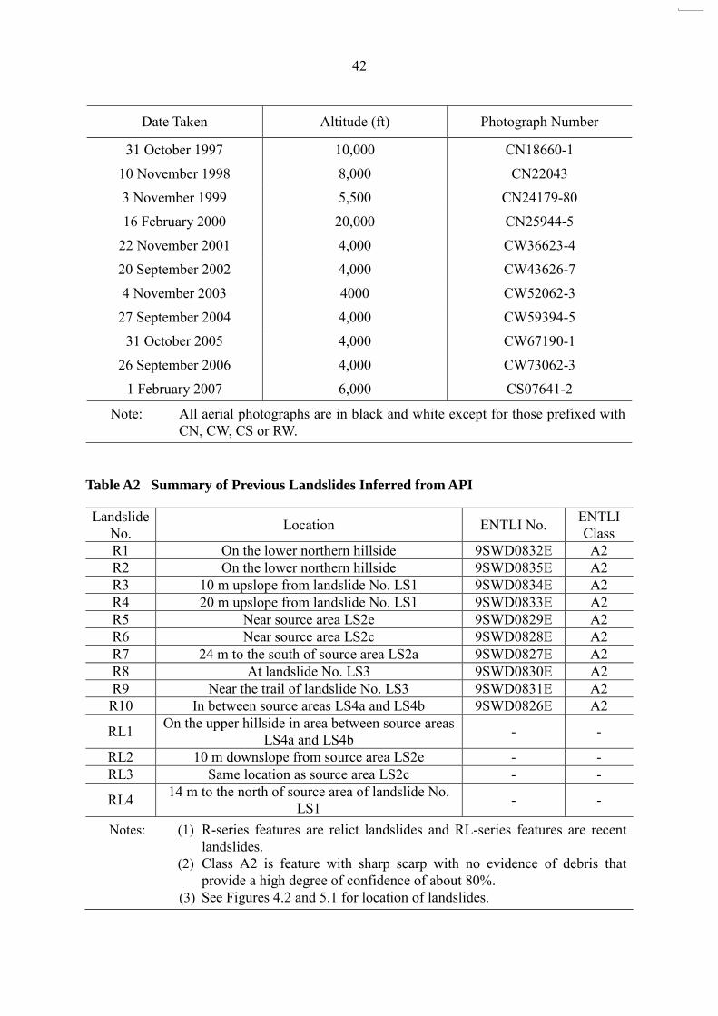
Date Taken Altitude (ft) Photograph Number
31 October 1997 10,000 CN18660-1
10 November 1998 8,000 CN22043
3 November 1999 5,500 CN24179-80
16 February 2000 20,000 CN25944-5
22 November 2001 4,000 CW36623-4
20 September 2002 4,000 CW43626-7
4 November 2003 4000 CW52062-3
27 September 2004 4,000 CW59394-5
31 October 2005 4,000 CW67190-1
26 September 2006 4,000 CW73062-3
1 February 2007 6,000 CS07641-2
Note: All aerial photographs are in black and white except for those prefixed with CN, CW, CS or RW.
Table A2 Summary of Previous Landslides Inferred from API
Landslide No. Location ENTLI No. ENTLI
Class R1 On the lower northern hillside 9SWD0832E A2 R2 On the lower northern hillside 9SWD0835E A2 R3 10 m upslope from landslide No. LS1 9SWD0834E A2 R4 20 m upslope from landslide No. LS1 9SWD0833E A2 R5 Near source area LS2e 9SWD0829E A2 R6 Near source area LS2c 9SWD0828E A2 R7 24 m to the south of source area LS2a 9SWD0827E A2 R8 At landslide No. LS3 9SWD0830E A2 R9 Near the trail of landslide No. LS3 9SWD0831E A2 R10 In between source areas LS4a and LS4b 9SWD0826E A2
RL1 On the upper hillside in area between source areas LS4a and LS4b - -
RL2 10 m downslope from source area LS2e - - RL3 Same location as source area LS2c - -
RL4 14 m to the north of source area of landslide No. LS1 - -
Notes: (1) R-series features are relict landslides and RL-series features are recent landslides.
(2) Class A2 is feature with sharp scarp with no evidence of debris that provide a high degree of confidence of about 80%.
(3) See Figures 4.2 and 5.1 for location of landslides.

43
Appendix B
Previous Engineer Inspection and Routine Maintenance Inspection

44
Contents
Page No.
Contents
44
B.1 Engineer Inspection and Routine Maintenance Inspection
45

45
B.1 Engineer Inspection and Routine Maintenance Inspection
A review of available records of Engineer Inspections (EI) and Routine Maintenance
Inspections (RMI) carried out for the Lands Department (Lands D) has been carried out. In January 1999, Halcrow China Limited (formerly Halcrow Asia Partnership Limited) carried out an Engineer Inspection (EI) for slope No. 9SW-D/C199. The overall state of maintenance of the slope was assessed as “Fair”. The EI report dated 1999 noted that a recent slope failure and localized erosion were found at the southern end of the feature (Figure 4.2). The debris mainly comprises “large boulders and poorly sorted materials”. Routine maintenance works comprising “re-grassing the bare soil slope surface area” were recommended. Preventive maintenance works were recommended for the slope which comprised "improve surface drainage by providing a slope crest channel with upstand" and "filling local areas on slope with compacted soil and vegetate".
In December 2001, Binnie Arup Joint Venture (BAJV) carried out an Engineer
Inspection (EI) for slope No. 9SW-D/C195. The overall state of maintenance of the slope was assessed as “Fair”. The EI report noted that minor erosion was found on the subject feature. Routine maintenance works comprising “Regrade eroded areas followed by re-grassing” and “Regrass the bare soil slope surface area” were recommended. Preventive maintenance works were recommended for the slope which comprised the provision of a slope crest channel with upstand.
In February 2006, Maunsell Geotechnical Services Limited (MGSL) carried out an
Engineer Inspection (EI) for slope No. 9SW-D/C194. The overall state of maintenance of the slope was assessed as “Fair”. Preventive maintenance works were recommended for the slope. These included “install soil nails” and “apply shotcrete with wire mesh and weepholes”. There were no records in Lands D or obvious observations after failure that indicated whether the recommendations were carried out or not.

46
Appendix C
Detailed Observations of the Landslides

47
Contents
Page No.
Contents
47
List of Figures 48
C.1 General 49 C.2 Landslide No. LS1 49 C.3 Landslide No. LS2 50 C.4 Landslide No. LS3 51 C.5 Landslide No. LS4 51 C.6 Landslide No. LS5
52

48
List of Figures
Figure No.
Page No.
C1
View of the Debris of Landslide No. LS1 confined to the
Open Area/Garden adjacent to House No. 4 (Photograph
Taken on 13 June 2008)
50
C2 Over-steepened Flank at Source Area LS4a (Photograph
Taken on 19 June 2008)
52

49
C.1 General
The five landslides (namely landslides Nos. LS1 to LS5) comprises several failures
source areas. Landslide No. LS1 has a single source area and is located on the northern portion of the lower hillside above slope No. 9SW-D/C199 and is at an elevation of about 16 mPD, the lowest of the landslides. Landslide No. LS2 is located on the hillside above slopes Nos. 9SW-D/C194 and 9SW-D/C200 behind house No. 7 and Tin Hau Temple, and mainly comprises five major source areas (namely LS2a to LS2e) with the highest elevation landslide source at approximately 52 mPD. The adjacent hillside is generally inclined at an angle of about 32° near LS2a and LS2b, and steepens to over 40° near LS2c to LS2e. Landslide No. LS3 mainly comprises a source area and is located on the middle part of the hillside behind houses Nos. 11 and 12, above slope No. 9SW-D/C201. Landslide No. LS4 mainly comprises two major source areas (namely LS4a and LS4b) and is located on the hillside behind houses Nos. 13 to 18, above slope No. 9SW-D/C195. Landslide No. LS5 has a single source area and is located on the hillside at the southern end of Tai O San Tsuen. The crowns of the source areas of landslides Nos. LS3 to LS5 are located at an elevation of about 56 mPD, and the adjacent hillside is generally inclined at an angle of approximately 34° to 40°. Tension cracks were observed adjacent to some of the source areas although all of these were considered recent.
C.2 Landslide No. LS1
This landslide is an open hillside failure and at and elevation of about 16 mPD, is the
lowest landslide inspected (Figure 5.5). The dimensions of the landslide source are about 12 m long, 10 m wide and 1.5 m deep. The rupture surface is steep (approximately 50°) and is mostly within partially weathered rock mass (PW 90/100). The main scarp consists of some partially weathered rock mass (PW 50/90) with a thin layer of colluvium. Rock was exposed above the main scarp for a distance of between 5 m and 10 m uphill (Figure 5.1). The rock is typically closely jointed and dilated due to stress relief.
The detached material mainly comprised partially weathered rock mass and colluvium
with a total volume of about 80 m3. The source floor material and the rock outcrop above the main scarp probably limited the extent of the landslide by retrogressive movement and deepening.
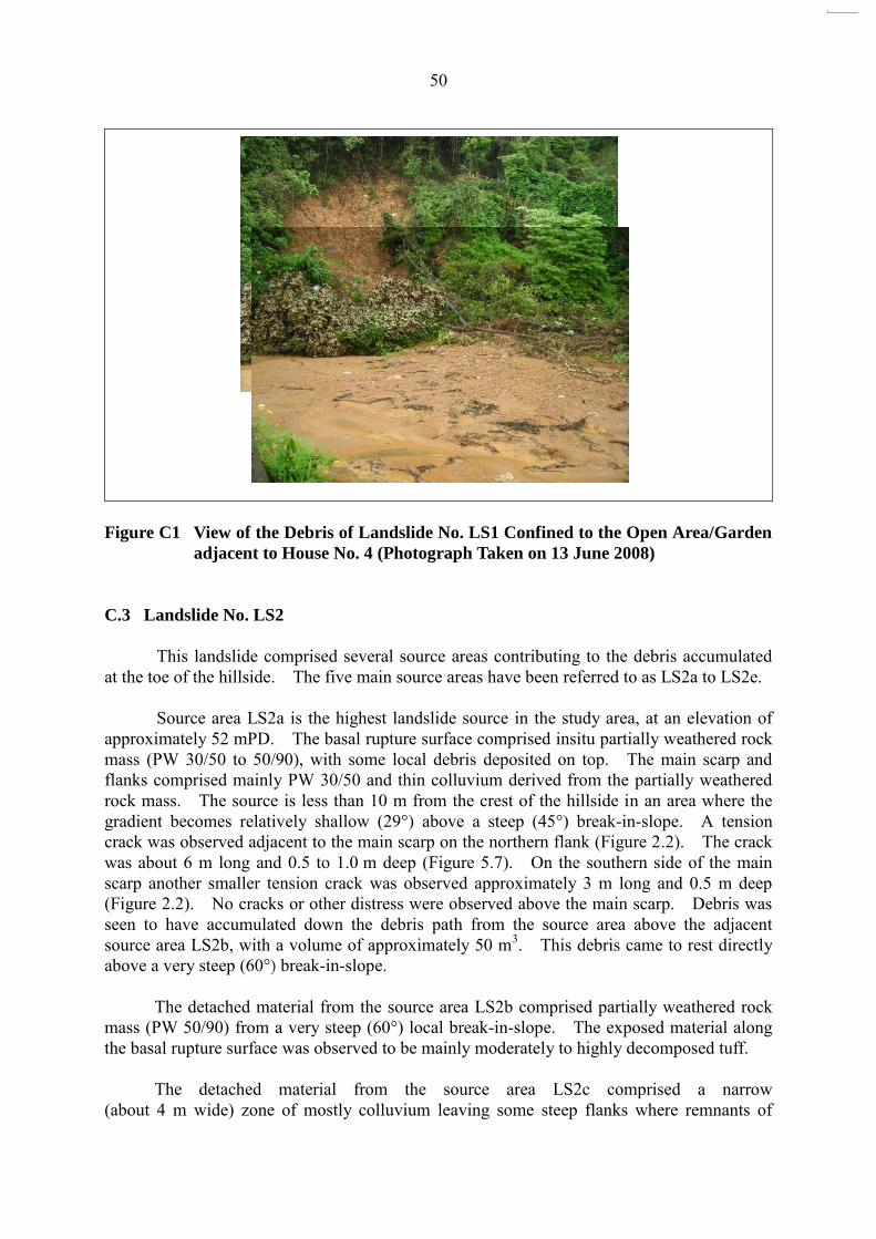
No distress was observed in the flanks or above the main scarp of the landslide,
although access was limited above the main scarp due to the very steep terrain. With a travel distance of 21 m, debris was confined to the garden and open area around one of the village houses at the toe of the hillside (Figure 5.4).
50
Figure C1 View of the Debris of Landslide No. LS1 Confined to the Open Area/Garden
adjacent to House No. 4 (Photograph Taken on 13 June 2008)
C.3 Landslide No. LS2
This landslide comprised several source areas contributing to the debris accumulated
at the toe of the hillside. The five main source areas have been referred to as LS2a to LS2e. Source area LS2a is the highest landslide source in the study area, at an elevation of
approximately 52 mPD. The basal rupture surface comprised insitu partially weathered rock mass (PW 30/50 to 50/90), with some local debris deposited on top. The main scarp and flanks comprised mainly PW 30/50 and thin colluvium derived from the partially weathered rock mass. The source is less than 10 m from the crest of the hillside in an area where the gradient becomes relatively shallow (29°) above a steep (45°) break-in-slope. A tension crack was observed adjacent to the main scarp on the northern flank (Figure 2.2). The crack was about 6 m long and 0.5 to 1.0 m deep (Figure 5.7). On the southern side of the main scarp another smaller tension crack was observed approximately 3 m long and 0.5 m deep (Figure 2.2). No cracks or other distress were observed above the main scarp. Debris was seen to have accumulated down the debris path from the source area above the adjacent source area LS2b, with a volume of approximately 50 m3. This debris came to rest directly above a very steep (60°) break-in-slope.
The detached material from the source area LS2b comprised partially weathered rock mass (PW 50/90) from a very steep (60°) local break-in-slope. The exposed material along the basal rupture surface was observed to be mainly moderately to highly decomposed tuff.
The detached material from the source area LS2c comprised a narrow (about 4 m wide) zone of mostly colluvium leaving some steep flanks where remnants of
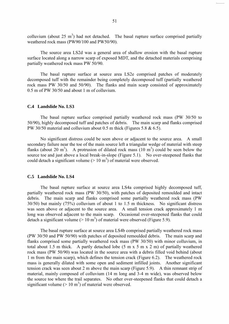
51
colluvium (about 25 m3) had not detached. The basal rupture surface comprised partially weathered rock mass (PW90/100 and PW50/90).
The source area LS2d was a general area of shallow erosion with the basal rupture
surface located along a narrow scarp of exposed MDT, and the detached materials comprising partially weathered rock mass PW 50/90.
The basal rupture surface at source area LS2e comprised patches of moderately
decomposed tuff with the remainder being completely decomposed tuff (partially weathered rock mass PW 30/50 and 50/90). The flanks and main scarp consisted of approximately 0.5 m of PW 30/50 and about 1 m of colluvium.
C.4 Landslide No. LS3
The basal rupture surface comprised partially weathered rock mass (PW 30/50 to
50/90), highly decomposed tuff and patches of debris. The main scarp and flanks comprised PW 30/50 material and colluvium about 0.5 m thick (Figures 5.8 & 6.5).
No significant distress could be seen above or adjacent to the source area. A small
secondary failure near the toe of the main source left a triangular wedge of material with steep flanks (about 20 m3). A protrusion of dilated rock mass (10 m3) could be seen below the source toe and just above a local break-in-slope (Figure 5.1). No over-steepened flanks that could detach a significant volume (> 10 m3) of material were observed. C.5 Landslide No. LS4
The basal rupture surface at source area LS4a comprised highly decomposed tuff, partially weathered rock mass (PW 30/50), with patches of deposited remoulded and intact debris. The main scarp and flanks comprised some partially weathered rock mass (PW 30/50) but mainly (75%) colluvium of about 1 to 1.5 m thickness. No significant distress was seen above or adjacent to the source area. A small tension crack approximately 1 m long was observed adjacent to the main scarp. Occasional over-steepened flanks that could detach a significant volume (> 10 m3) of material were observed (Figure 5.9).
The basal rupture surface at source area LS4b comprised partially weathered rock mass
(PW 30/50 and PW 50/90) with patches of deposited remoulded debris. The main scarp and flanks comprised some partially weathered rock mass (PW 30/50) with minor colluvium, in total about 1.5 m thick. A partly detached lobe (5 m x 5 m x 2 m) of partially weathered rock mass (PW 50/90) was located in the source area with a debris filled void behind (about 1 m from the main scarp), which defines the tension crack (Figure 6.2). The weathered rock mass is generally dilated with some open and sediment infilled joints. Another significant tension crack was seen about 2 m above the main scarp (Figure 5.9). A thin remnant strip of material, mainly composed of colluvium (14 m long and 3-4 m wide), was observed below the source toe where the trail separates. No other over-steepened flanks that could detach a significant volume (> 10 m3) of material were observed.

52
Figure C2 Over-steepened Flank at Source Area LS4a (Photograph Taken on
19 June 2008)
C.6 Landslide No. LS5
The basal rupture surface comprised partially weathered rock mass (PW 30/50 and
PW 50/90) with some highly decomposed tuff patches and local debris deposits. The main scarp and flanks comprised PW 30/50 and colluvium of about 0.5 m thickness respectively (Figure 5.5).
No significant distress could be seen above or adjacent to the source area. A small
tension crack adjacent to the main scarp was observed but only for about 1 m. No over-steepened flanks that could detach a significant volume (> 10 m3) of material were observed.

GEO PUBLICATIONS AND ORDERING INFORMATION土力工程處刊物及訂購資料
A selected list of major GEO publications is given in the next page. An up-to-date full list of GEO publications can be found at the CEDD Website http://www.cedd.gov.hk on the Internet under “Publications”. Abstracts for the documents can also be found at the same website. Technical Guidance Notes are published on the CEDD Website from time to time to provide updates to GEO publications prior to their next revision.
部份土力工程處的主要刊物目錄刊載於下頁。而詳盡及最新的
土力工程處刊物目錄,則登載於土木工程拓展署的互聯網網頁
http://www.cedd.gov.hk 的“刊物”版面之內。刊物的摘要及更新
刊物內容的工程技術指引,亦可在這個網址找到。
Copies of GEO publications (except geological maps and other publications which are free of charge) can be purchased either by:
讀者可採用以下方法購買土力工程處刊物(地質圖及免費刊物除外):
Writing toPublications Sales Section,Information Services Department,Room 402, 4th Floor, Murray Building,Garden Road, Central, Hong Kong.Fax: (852) 2598 7482
書面訂購
香港中環花園道
美利大廈4樓402室
政府新聞處
刊物銷售組
傳真: (852) 2598 7482
or- Calling the Publications Sales Section of Information Services Department (ISD) at (852) 2537 1910- Visiting the online Government Bookstore at http:// www.bookstore.gov.hk- Downloading the order form from the ISD website at http://www.isd.gov.hk and submitting the order online or by fax to (852) 2523 7195- Placing order with ISD by e-mail at [email protected]
或
- 致電政府新聞處刊物銷售小組訂購 (電話:(852) 2537 1910)- 進入網上「政府書店」選購,網址為
http://www.bookstore.gov.hk- 透過政府新聞處的網站 (http://www.isd.gov.hk) 於網上遞交
訂購表格,或將表格傳真至刊物銷售小組 (傳真:(852) 2523 7195)- 以電郵方式訂購 (電郵地址:[email protected])
1:100 000, 1:20 000 and 1:5 000 geological maps can be purchased from:
讀者可於下列地點購買1:100 000、1:20 000及1:5 000地質圖:
Map Publications Centre/HK,Survey & Mapping Office, Lands Department,23th Floor, North Point Government Offices,333 Java Road, North Point, Hong Kong.Tel: (852) 2231 3187Fax: (852) 2116 0774
香港北角渣華道333號
北角政府合署23樓
地政總署測繪處
電話: (852) 2231 3187傳真: (852) 2116 0774
Requests for copies of Geological Survey Sheet Reports and other publications which are free of charge should be directed to:
如欲索取地質調查報告及其他免費刊物,請致函:
For Geological Survey Sheet Reports which are free of charge:Chief Geotechnical Engineer/Planning,(Attn: Hong Kong Geological Survey Section)Geotechnical Engineering Office,Civil Engineering and Development Department,Civil Engineering and Development Building,101 Princess Margaret Road,Homantin, Kowloon, Hong Kong.Tel: (852) 2762 5380Fax: (852) 2714 0247E-mail: [email protected]
免費地質調查報告:
香港九龍何文田公主道101號
土木工程拓展署大樓
土木工程拓展署
土力工程處
規劃部總土力工程師
(請交:香港地質調查組)電話: (852) 2762 5380傳真: (852) 2714 0247電子郵件: [email protected]
For other publications which are free of charge:Chief Geotechnical Engineer/Standards and Testing,Geotechnical Engineering Office,Civil Engineering and Development Department,Civil Engineering and Development Building,101 Princess Margaret Road,Homantin, Kowloon, Hong Kong.Tel: (852) 2762 5346Fax: (852) 2714 0275E-mail: [email protected]
其他免費刊物:
香港九龍何文田公主道101號
土木工程拓展署大樓
土木工程拓展署
土力工程處
標準及測試部總土力工程師
電話: (852) 2762 5346傳真: (852) 2714 0275電子郵件: [email protected]
MAJOR GEOTECHNICAL ENGINEERING OFFICE PUBLICATIONS土力工程處之主要刊物
GEOTECHNICAL MANUALS
Geotechnical Manual for Slopes, 2nd Edition (1984), 302 p. (English Version), (Reprinted, 2011).斜坡岩土工程手冊(1998),308頁(1984年英文版的中文譯本)。Highway Slope Manual (2000), 114 p.
GEOGUIDES
Geoguide 1 Guide to Retaining Wall Design, 2nd Edition (1993), 258 p. (Reprinted, 2007).Geoguide 2 Guide to Site Investigation (1987), 359 p. (Reprinted, 2000).Geoguide 3 Guide to Rock and Soil Descriptions (1988), 186 p. (Reprinted, 2000).Geoguide 4 Guide to Cavern Engineering (1992), 148 p. (Reprinted, 1998).Geoguide 5 Guide to Slope Maintenance, 3rd Edition (2003), 132 p. (English Version).岩土指南第五冊 斜坡維修指南,第三版(2003),120頁(中文版)。Geoguide 6 Guide to Reinforced Fill Structure and Slope Design (2002), 236 p.Geoguide 7 Guide to Soil Nail Design and Construction (2008), 97 p.
GEOSPECS
Geospec 1 Model Specification for Prestressed Ground Anchors, 2nd Edition (1989), 164 p. (Reprinted, 1997).
Geospec 3 Model Specification for Soil Testing (2001), 340 p.
GEO PUBLICATIONS
GCO PublicationNo. 1/90
Review of Design Methods for Excavations (1990), 187 p. (Reprinted, 2002).
GEO PublicationNo. 1/93
Review of Granular and Geotextile Filters (1993), 141 p.
GEO PublicationNo. 1/2006
Foundation Design and Construction (2006), 376 p.
GEO PublicationNo. 1/2007
Engineering Geological Practice in Hong Kong (2007), 278 p.
GEO PublicationNo. 1/2009
Prescriptive Measures for Man-Made Slopes and Retaining Walls (2009), 76 p.
GEO PublicationNo. 1/2011
Technical Guidelines on Landscape Treatment for Slopes (2011), 217 p.
GEOLOGICAL PUBLICATIONS
The Quaternary Geology of Hong Kong, by J.A. Fyfe, R. Shaw, S.D.G. Campbell, K.W. Lai & P.A. Kirk (2000), 210 p. plus 6 maps.The Pre-Quaternary Geology of Hong Kong, by R.J. Sewell, S.D.G. Campbell, C.J.N. Fletcher, K.W. Lai & P.A. Kirk (2000), 181 p. plus 4 maps.
TECHNICAL GUIDANCE NOTES
TGN 1 Technical Guidance Documents