Embed Size (px)
Citation preview

Review of Series Compensationfor Transmission Lines
FINAL
Prepared by John MillerMarc Brunet-WatsonJed LeighfieldPSC North America
For Southwest Power Pool
PSC reference JU4715
Date May 09, 2014
Proprietary & Confidential
Review of Series Compensation for Transmission Lines
PSC North America – Power Networks Page 2 of 65
Revision Table
Revision Issue Date Description
1 3/21/2014 Final Draft for submission to client2 4/16/2014 Final submission.
2.1 5/09/2014 Final with corrections:- general typos,- fig 2.2 – show impact of increasing K- fig 2.3 - removed FSC- fig 6.3 – reversed light load and SIL curves
Reviewers
Name Interest Date
Andrew Robbie Principal Engineer 3/17/2014Brad Railing Principal Engineer 4/14/2014
Approval
Name Position Date
Marc Brunet-Watson Power Networks Manager 5/09/2014
Review of Series Compensation for Transmission Lines
PSC North America – Power Networks Page 3 of 65
TABLE OF CONTENTS
1.......... Introduction ..........................................................................................7
2..........Applicability of Series Compensation Technology ...........................9
2.1 General Review ...................................................................................... 9
2.1.1 Reducing Rotor Angle Separation................................................... 9
2.1.2 Voltage Regulation........................................................................ 11
2.2 Fixed Series Compensation (FSC)...................................................... 13
2.3 Thyristor Controlled Series Compensation (TCSC)........................... 14
3..........Sub-synchronous Interaction with Series Compensation..............16
3.1 Key Section References ...................................................................... 16
3.2 Sub-synchronous Interaction.............................................................. 16
3.2.1 Fundamentals of Series Compensation and SSI ........................... 17
3.2.2 Classic SSR-TI and SSR-TA......................................................... 18
3.2.3 Induction Generator Effect (IGE)................................................... 19
3.2.4 SSCI Considerations for Wind Generation .................................... 20
3.3 Assessment of SSI in Series Compensated Networks...................... 21
3.3.1 SSI Analysis.................................................................................. 21
3.3.2 Frequency Scan Screening........................................................... 22
3.3.3 Eigenvalue Analysis ...................................................................... 23
3.3.4 Damping Torque Analysis ............................................................. 24
3.3.5 Detailed Time-Domain Analysis .................................................... 24
3.4 ERCOT – SSI Impact Study Framework for Wind Generators........... 25
4..........SSI Mitigation and Protection Measures and Practical Applications26
4.1 Key Section References ...................................................................... 26
4.2 General Considerations and Definitions ............................................ 26
4.3 Network-Based Mitigation Measures .................................................. 27
4.3.1 Operational Procedures ................................................................ 27
4.3.2 Passive Filter Damping ................................................................. 27
4.3.3 Active Shunt Filter Damping (SVC or STATCOM)......................... 28
4.3.4 Active Series Damping (TCSC) and Shunt-Series Damping (UPFC)28
4.4 Generator-Based Mitigation Measures ............................................... 30
4.4.1 Passive Filter Damping ................................................................. 30
4.4.2 Active Filter Damping.................................................................... 31

Review of Series Compensation for Transmission Lines
PSC North America – Power Networks Page 4 of 65
4.4.3 Supplementary Excitation Control Damping .................................. 31
4.4.4 Wind Turbine Control Damping ..................................................... 32
4.5 Network-Based Protection Measure ................................................... 33
4.5.1 Series Capacitor By-pass.............................................................. 33
4.6 Generator-Based Protection Measures .............................................. 33
4.6.1 SSI Relays .................................................................................... 33
5..........Protection Schemes and Protection Relay Considerations ...........35
5.1 Key Section References ...................................................................... 35
5.2 General ................................................................................................. 35
5.3 Influence of Capacitor Protection ....................................................... 36
5.3.1 Voltage Inversion and Current Inversion ....................................... 36
5.3.2 Distance Protection – Measured Impedance................................. 38
5.3.3 Sub-synchronous Transient Signal Impacts .................................. 39
5.3.4 Adjacent Line Protection Impacts.................................................. 40
5.3.5 Other Impacts ............................................................................... 41
5.3.6 Automatic Reclosing for Series Compensated Transmission Lines41
5.4 Relay Protection Solutions.................................................................. 43
5.4.1 Advanced Relays for Series Compensation Application ................ 43
5.4.2 Protection Schemes...................................................................... 44
5.4.3 Protection Design and Performance Verification ........................... 45
5.5 Protection Case Studies ...................................................................... 46
5.5.1 BC Hydro ...................................................................................... 46
5.5.2 Hydro-Québec TransÉnergie (HQT).............................................. 49
5.5.3 Pacific Gas & Electric.................................................................... 50
6..........Project Planning and Implementation Considerations ...................52
6.1 Key Section References ...................................................................... 52
6.2 Location of Series Compensation....................................................... 52
6.2.1 Mid-Line ........................................................................................ 53
6.2.2 Line Ends...................................................................................... 55
6.3 Modularity of Series Compensation ................................................... 57
6.4 Future Development of the Series Compensated Lines.................... 58
6.5 Operations and Maintenance Considerations.................................... 58
6.5.1 Operations and Reliability ............................................................. 59
7..........Roadmap for Further Analysis ..........................................................60
7.1 Preliminary Design Stage Studies ...................................................... 60

Review of Series Compensation for Transmission Lines
PSC North America – Power Networks Page 5 of 65
7.2 Steady state data for analyzing the active and reactive power flows andvoltage profiles in the system............................................................. 60
7.3 Transient Stability Analysis................................................................. 61
7.4 Harmonics and Frequency Scans....................................................... 61
7.5 Short-term Transient Voltage and Switching Studies ....................... 61
7.6 Small-signal Analysis .......................................................................... 62
8..........References..........................................................................................63

Review of Series Compensation for Transmission Lines
PSC North America – Power Networks Page 6 of 65
TABLE OF FIGURES
Figure 2-1 - Power transfer equation
Figure 2-2 - Pmax with all lines in service
Figure 2-3 - Equal Area Criterion for a simple system
Figure 2-4 - Self-regulation of series compensation – 500 kV line, 300 miles long
Figure 2-5 – Effect of increasing compensation levels – 500 kV line, 300 miles long
Figure 2-6 - FSC main circuit components
Figure 2-7 - TCSC primary circuit components
Figure 3-1 - Generator turbine lumped mass model
Figure 3-2 - System electrical damping vs. torsional frequency (w/torsional modes) Source
[4]
Figure 4-1 - Passive filter in parallel with series capacitor
Figure 4-2 - Primary components of a TCSC
Figure 4-3 - TCSC impedance characteristic with SVR. Source: [2]
Figure 4-4 - DFIG Basic One-Line (Type-3)
Figure 5-1 - MOV protected series capacitor
Figure 5-2 - Voltage profile for a line side fault near a series capacitor (Forward Fault)
Figure 5-3 - Voltage profile for an adjacent line side fault near a series capacitor (Reverse
Fault)
Figure 5-4 - Example of current reversal condition in a SC line
Figure 5-5 - Impedance protection on a mid-point SC line
Figure 5-6 - Transmission line with remote line end SC
Figure 5-7 - Distance relay overreach due to sub-synchronous transient signals
Figure 5-8 - Zone 1 distance relay on SC line (solid) and adjacent line (dotted)
Figure 5-9 Main and back-up proctection schemes for line end and mid-line SC Source:
[33]
Figure 6-1 - Midline compensation at 33% and 66% of line length
Figure 6-2 - Mid-line compensation at 50% of line length
Figure 6-3 – Line voltage profile for mid-line series compensation
Figure 6-4 - Line end compensation, bus side shunt reactors
Figure 6-5 - Line end compensation, line side shunt reactors
Figure 6-6 – Line voltage profile for line-end series compensation

Review of Series Compensation for Transmission Lines
PSC North America – Power Networks Page 7 of 65
1 Introduction
The High Priority Incremental Load Study (HPILS) was initiated in 2013 to develop along range plan that identified system reinforcements required in the Southwest PowerPool (SPP) footprint in order to accommodate the unprecedented load growth that hadnot been identified by previous planning studies. This rapid expansion of load wasbrought about by an increase in the development of oil and gas fields, the firming ofpreviously interruptible loads and an increase in the forecast expansion of majorindustrial loads.
As part of the HPILS process, initial screening of options by SPP staff suggested that50% series compensation (SC) should be considered on the existing Tolk - EddyCountry 345kV line as part of a potential EHV solution set to address the reliability needsassociated with large load additions in southeast New Mexico and west Texas. Due tothe fact that the proposed solution would introduce the first series compensated line inthe SPP footprint, significant concerns and uncertainties were expressed about themerits and implications of adding SC to existing or planned EHV lines in SPP.
Series compensation has been in use in electrical networks worldwide since the 1950s.It is a tried and true technology that continues to grow in popularity as an effectivemeans of resolving a number of network issues such as:
Improving transient system performance of the system following systemdisturbances by reducing rotor angle difference between generators;
Compensating for reactive power losses in transmission lines to better regulatesystem voltages;
Modifying and improving the balance of power flows between adjacenttransmission corridors by changing impedances, similar in effect to phase-shifting transformers and HVDC;
Damping of system oscillations when used with actively controlled ThyristorControlled Series Capacitors (see Section 2.3); and
Mitigating geomagnetic induced currents by blocking low frequency current flow.
The first two points are further discussed in Sections 2.1.1 and 2.1.2 whereas theremainder are beyond the scope of this paper.
By addressing the above issues with less capital intensive solutions such as seriescompensation, the capacity of existing transmission lines can be increased therebyallowing for the deferral of major transmission line investments and the optimization oftotal build out. This permits better management of risk through the preservation of rightof ways and corridors for future needs using an option that requires minimal permittingand siting requirements. Overall asset utilization increases and losses are lowered.Series compensation improves system reliability while minimizing the impact on ratepayers.
The various sub synchronous interactions between the network and the series capacitorare well known phenomena and there are a variety of ways available to counter-actthem. The literature on the topic is extensive and the techniques are well documentedand their relative merits are discussed at length.
Review of Series Compensation for Transmission Lines
PSC North America – Power Networks Page 8 of 65
This document seeks to provide a better understanding of the implications of addingseries compensation technology to the SPP network. The current status of thetechnology is reviewed and recent advances in the techniques that deal with knownissues that affect the network are explored.
Review of Series Compensation for Transmission Lines
PSC North America – Power Networks Page 9 of 65
2 Applicability of Series Compensation Technology
2.1 General Review
A general review of the applicability of series compensation shows that it serves toincrease power transfer under steady state and transient conditions, as well asregulating voltage variations. A series compensation installation can be ‘Fixed’,‘Thyristor Controlled’, or a combination of both.
2.1.1 Reducing Rotor Angle Separation
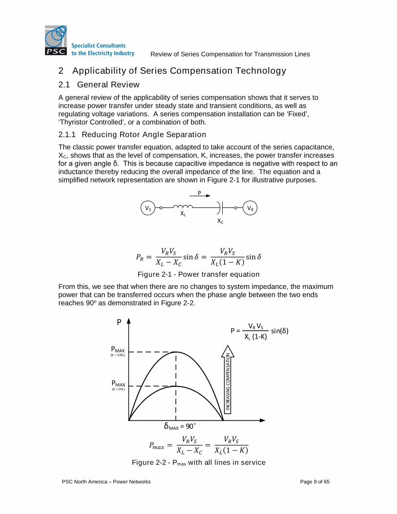
The classic power transfer equation, adapted to take account of the series capacitance,XC, shows that as the level of compensation, K, increases, the power transfer increasesfor a given angle δ. This is because capacitive impedance is negative with respect to an inductance thereby reducing the overall impedance of the line. The equation and asimplified network representation are shown in Figure 2-1 for illustrative purposes.
VS VR
P
XL
XC
ோ =ோ ௌ
− sinߜ=
ோ ௌ
(1 − (ܭsinߜ
Figure 2-1 - Power transfer equation
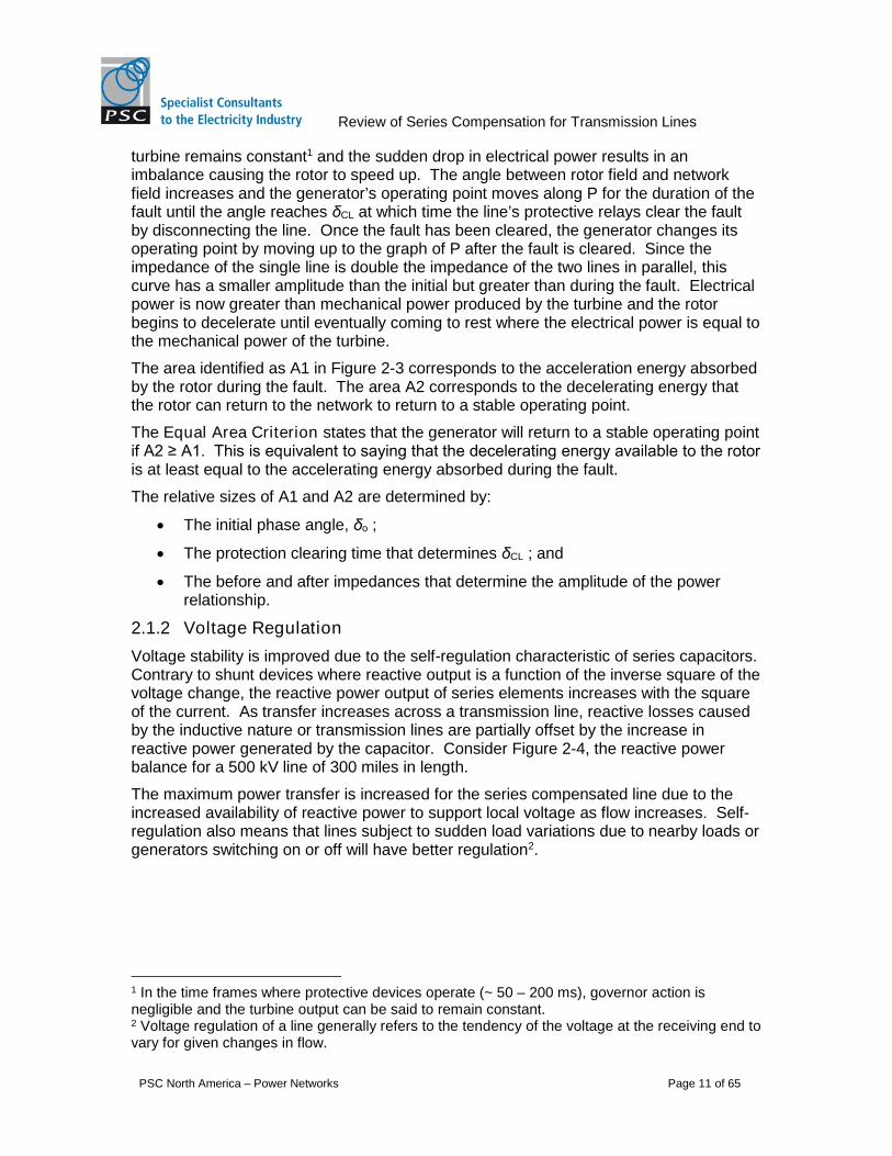
From this, we see that when there are no changes to system impedance, the maximumpower that can be transferred occurs when the phase angle between the two endsreaches 90o as demonstrated in Figure 2-2.
P
δMAX = 90
PMAX(K = 0%)
VR VS
XL (1-K)sin(δ)P =
PMAX(K = 50%)
INC
REA
SIN
GC
OM
PEN
SATI
ON
௫ =ோ ௌ
− =
ோ ௌ
(1 − (ܭ
Figure 2-2 - Pmax with all lines in service

Review of Series Compensation for Transmission Lines
PSC North America – Power Networks Page 10 of 65
The effect of adding series compensation is shown in Figure 2-2 where for a same angleδMAX, the theoretical maximum power transfer, PMAX, doubles when compensation level,K, reaches 50%. Analogously, for a given power flow (say PMAX when K=0%), rotorangle separation goes from 90o with no compensation to a much smaller value whencompensation is increased.
As faults occur and branch elements are switched out of service, the resulting changesin network impedance cause imbalances between the electrical and mechanical torquesat play in the generator and an oscillatory behavior, best characterized by the swingequation:
ܪ2
௦
ଶߜ
ଶݐ= −
where H is generator inertia, ωs = 2 π fs is synchronous angular speed, Pmec is themechanical power generated by the turbine, Pelec is the electrical power generated by thealternator that responds to the system demand. During steady state, when the systemfrequency is at its nominal 60 Hz, both the mechanical and electrical power are equaland the machine continues to spin at synchronous speeds.
Pelec
FAULT
Pmec
VRVS
A1
A2
δ
Pmec
δMAX
Pelec after fault cleared(one line out)
Pelec both lines in service
Pelec during fault
δCL δO
Pelec
Figure 2-3 - Equal Area Criterion for a simple system
Prior to fault inception, the generator in Figure 2-3 has angle δo and is generating Pmec
on the Pelec curve with both lines in service. At the instant of the fault, the impedanceseen by the generator reduces and very little active power is generated due to the faultbeing situated between the load and the generator. The generator’s operating point isnow where δo crosses the curve of P during the fault. Mechanical power from the
Review of Series Compensation for Transmission Lines
PSC North America – Power Networks Page 11 of 65
turbine remains constant1 and the sudden drop in electrical power results in animbalance causing the rotor to speed up. The angle between rotor field and networkfield increases and the generator’s operating point moves along P for the duration of thefault until the angle reaches δCL at which time the line’s protective relays clear the faultby disconnecting the line. Once the fault has been cleared, the generator changes itsoperating point by moving up to the graph of P after the fault is cleared. Since theimpedance of the single line is double the impedance of the two lines in parallel, thiscurve has a smaller amplitude than the initial but greater than during the fault. Electricalpower is now greater than mechanical power produced by the turbine and the rotorbegins to decelerate until eventually coming to rest where the electrical power is equal tothe mechanical power of the turbine.
The area identified as A1 in Figure 2-3 corresponds to the acceleration energy absorbedby the rotor during the fault. The area A2 corresponds to the decelerating energy thatthe rotor can return to the network to return to a stable operating point.
The Equal Area Criterion states that the generator will return to a stable operating pointif A2 ≥ A1. This is equivalent to saying that the decelerating energy available to the rotor is at least equal to the accelerating energy absorbed during the fault.
The relative sizes of A1 and A2 are determined by:
The initial phase angle, δo ;
The protection clearing time that determines δCL ; and
The before and after impedances that determine the amplitude of the powerrelationship.
2.1.2 Voltage Regulation
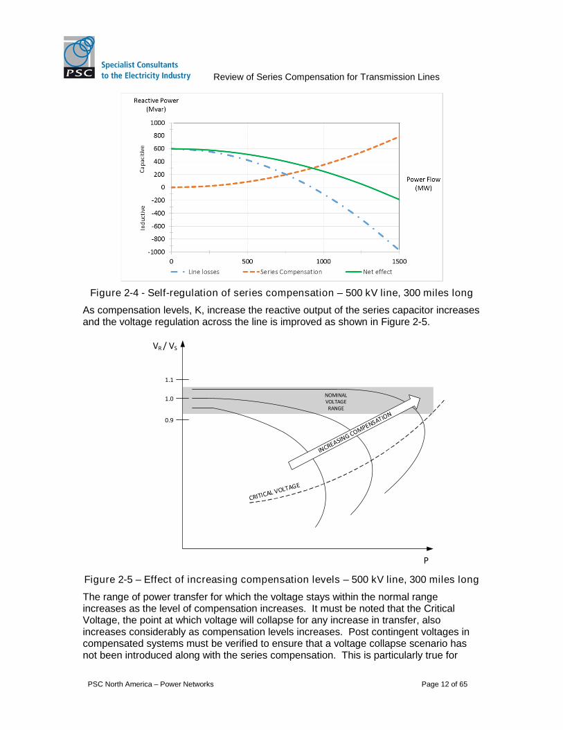
Voltage stability is improved due to the self-regulation characteristic of series capacitors.Contrary to shunt devices where reactive output is a function of the inverse square of thevoltage change, the reactive power output of series elements increases with the squareof the current. As transfer increases across a transmission line, reactive losses causedby the inductive nature or transmission lines are partially offset by the increase inreactive power generated by the capacitor. Consider Figure 2-4, the reactive powerbalance for a 500 kV line of 300 miles in length.
The maximum power transfer is increased for the series compensated line due to theincreased availability of reactive power to support local voltage as flow increases. Self-regulation also means that lines subject to sudden load variations due to nearby loads orgenerators switching on or off will have better regulation2.
1 In the time frames where protective devices operate (~ 50 – 200 ms), governor action isnegligible and the turbine output can be said to remain constant.2 Voltage regulation of a line generally refers to the tendency of the voltage at the receiving end tovary for given changes in flow.
Review of Series Compensation for Transmission Lines
PSC North America – Power Networks Page 12 of 65
Figure 2-4 - Self-regulation of series compensation – 500 kV line, 300 miles long
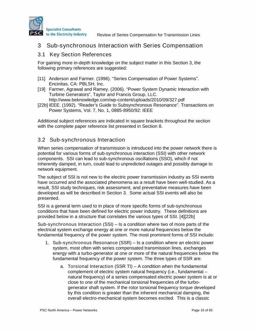
As compensation levels, K, increase the reactive output of the series capacitor increasesand the voltage regulation across the line is improved as shown in Figure 2-5.
0.9
1.0
1.1
VR / VS
P
NOMINALVOLTAGE
RANGE
Figure 2-5 – Effect of increasing compensation levels – 500 kV line, 300 miles long
The range of power transfer for which the voltage stays within the normal rangeincreases as the level of compensation increases. It must be noted that the CriticalVoltage, the point at which voltage will collapse for any increase in transfer, alsoincreases considerably as compensation levels increases. Post contingent voltages incompensated systems must be verified to ensure that a voltage collapse scenario hasnot been introduced along with the series compensation. This is particularly true for

Review of Series Compensation for Transmission Lines
PSC North America – Power Networks Page 13 of 65
situations where unplanned outages result in unusually high flows across compensatedlines.
2.2 Fixed Series Compensation (FSC)
A fixed series compensation installation consists of a parallel combination of capacitors,over-voltage protection, and a bypass breaker, which are all installed on an elevatedplatform insulated to the line voltage. The FSC main circuit components are shown inFigure 2-6. The capacitor bank is usually rated to line currents associated with normalpeak power flow and power swing conditions. Rating the capacitor banks to current andvoltage levels associated with fault conditions is generally not considered economicaland over voltage protection is provided to limit the voltage across the capacitor duringfault conditions. The over voltage protection typically consists of two parts:
A zinc oxide varistor (MOV) with highly non-linear characteristics that conductsnegligible current during normal operation and conducts freely once the voltageacross it reaches the protection level thereby bypassing the capacitor bank. TheMOV is built up of individual MOV blocks placed in series to obtain the desiredvoltage protection level and in parallel to be to absorb the desired energy duringfaults. If the fault is cleared without the ratings of the MOV being exceeded, theMOV will stop conducting once the voltage across it drops below the protection leveland the capacitor will return to normal operating conditions.
A fast protective device (FPD) that can be triggered for certain fault conditions suchas faults on compensated line segments or for extreme faults when the energyabsorbed by the MOV exceeds rated values. Fast protective devices have typicallyconsisted of triggered air gaps although new technologies are being introduced thatuse arc-plasma injectors in parallel with a fast contact to avoid the difficulty ofcorrectly distancing and maintaining the electrodes in the air gap.
The bypass breaker is normally in the open position and can be used to switch the seriescapacitor in or out during planned operations. It also serves to bypass the seriescapacitor, MOV and FPD if the fault is not cleared within a pre-determined time. It mustbe able to carry the rated MOV voltage as well as the maximum capacitor dischargecurrent. Bypass breakers are specially designed and rated to withstand the highertransient frequency and interrupting currents when bypassing a series capacitor. Bypassbreakers are normally SF6 puffer type with controls at ground level.
A damping circuit - usually an air core reactor - is placed in series with the FPD and theby-pass breaker to limit and dampen capacitor discharge currents when the FPD triggersor the bypass breaker is closed.

Review of Series Compensation for Transmission Lines
PSC North America – Power Networks Page 14 of 65
Series Capacitor
Bypass Switch
MOV
FPD
Fixed Series Compensation
DampingReactor
Figure 2-6 - FSC main circuit components
2.3 Thyristor Controlled Series Compensation (TCSC)
A thyristor controlled series compensation installation typically consists of two modulesconnected in series:
A fixed series compensation module (as described above), and
A module consisting of a series capacitor in parallel with a thyristor controlled, air-core reactor.
As with the FSC, the TCSC is platform mounted and insulated at line voltage. A TCSCinstallation can be green field or thyristors can be added to control part or all of anexisting FSC installation [2].
When the thyristor gate is blocked, full current flows through the capacitance and the lineis fully compensated. When the thyristor gate is fully conducting, the capacitor iseffectively bypassed. If the valves are gated for partial conductance, it is possible tosmoothly vary the impedance of the TCSC.
Over-voltage protection is assured by the connection of an MOV across the capacitor. Abypass breaker or disconnect is generally included to allow for maintenance and betterover-voltage protection.
Depending on the network requirements TCSC installations may be 100% variablealthough most typically have a fixed level of compensation combined with a variablelevel of compensation as shown in Figure 2-7. This allows the cost to be optimized byonly controlling the series capacitance that provides reliability or other benefits. Thecontrolled part can be scaled as required.

Review of Series Compensation for Transmission Lines
PSC North America – Power Networks Page 15 of 65
Series Capacitor
MOV
Thyristors
Reactor
Thyristor Controlled Series Compensation
Series Capacitor
Bypass Switch
MOV
FPD
Fixed Series Compensation
DampingReactor
Bypass Switch
FPD
DampingReactor
Figure 2-7 - TCSC primary circuit components
Review of Series Compensation for Transmission Lines
PSC North America – Power Networks Page 16 of 65
3 Sub-synchronous Interaction with Series Compensation
3.1 Key Section References
For gaining more in-depth knowledge on the subject matter in this Section 3, thefollowing primary references are suggested:
[11] Anderson and Farmer. (1996). “Series Compensation of Power Systems”.Encinitas, CA: PBLSH, Inc.
[19] Farmer, Agrawal and Ramey. (2006). “Power System Dynamic Interaction withTurbine Generators”, Taylor and Francis Group, LLC.http://www.beknowledge.com/wp-content/uploads/2010/09/327.pdf
[22b] IEEE. (1992). “Reader’s Guide to Subsynchronous Resonance”. Transactions onPower Systems, Vol. 7, No. 1, 0885-8950/92: IEEE
Additional subject references are indicated in square brackets throughout the sectionwith the complete paper reference list presented in Section 8.
3.2 Sub-synchronous Interaction
When series compensation of transmission is introduced into the power network there ispotential for various forms of sub-synchronous interaction (SSI) with other networkcomponents. SSI can lead to sub-synchronous oscillations (SSO), which if notinherently damped, in turn, could lead to unpredicted outages and possibly damage tonetwork equipment.
The subject of SSI is not new to the electric power transmission industry as SSI eventshave occurred and the associated phenomena as a result have been well-studied. As aresult, SSI study techniques, risk assessment, and preventative measures have beendeveloped as will be described in Section 3. Some actual SSI events will also bepresented.
SSI is a general term used to in place of more specific forms of sub-synchronousconditions that have been defined for electric power industry. These definitions areprovided below in a structure that correlates the various types of SSI. [4][22b]
Sub-synchronous Interaction (SSI) – Is a condition where two of more parts of theelectrical system exchange energy at one or more natural frequencies below thefundamental frequency of the power system. The most prominent forms of SSI include:
1. Sub-synchronous Resonance (SSR) – Is a condition where an electric powersystem, most often with series compensated transmission lines, exchangesenergy with a turbo-generator at one or more of the natural frequencies below thefundamental frequency of the power system. The three types of SSR are:
a. Torsional Interaction (SSR TI) – A condition when the fundamentalcomplement of electric system natural frequency (i.e., fundamental –natural frequency) of a series compensated electric power system is at orclose to one of the mechanical torsional frequencies of the turbo-generator shaft system. If the rotor torsional frequency torque developedby this condition is greater than the inherent mechanical damping, theoverall electro-mechanical system becomes excited. This is a classic

Review of Series Compensation for Transmission Lines
PSC North America – Power Networks Page 17 of 65
SSR condition which was defined following a damaging oscillatory eventsinvolving a turbine-generator (Mohave Generating Station) and a seriescompensated transmission line back in 1970 and 1971 in Nevada, USA.
b. Self-excitation due to Induction Generator Effect (IGE) – A condition,independent of the generator shaft torsional modes, where the combinedgenerator and electric power system results in a negative effective rotorresistance at a natural frequency below fundamental frequency. If thenegative rotor resistance is greater than the apparent stator plus networkresistance, self-excited, sub-synchronous current and electromagnetictorque in the machine can result. This phenomenon is a purely electricresonance condition.
c. Torque Amplification (SSR TA) – A condition where transient torquesamplify turbo-generator shaft system stress resulting from sub-synchronous currents due to a major disturbances in the power network.These torques are proportional to the magnitude of sub-synchronouscurrent, so transient current due to a short circuit and fault clearing canproduce large torques, particularly if the transient current’s frequencycomplements a shaft torsional mode.
2. Sub-synchronous Control Interaction (SSCI) – An electric power systemcondition where a power electronic device (such as HVDC, SVC, STATCOM,wind turbine control etc.) interacts, at a natural frequency, with the electric powernetwork containing near-by series compensated transmission.
3. Sub-synchronous Torsional Interaction (SSTI) – A condition involving controlinteractions between a power electronic device (such as an HVDC link, SVC,wind turbine etc.) and the mechanical mass system of a turbo-generator.
While SSTI is not associated with series compensation, the definition is provided abovefor completeness and differentiation from the other SSI forms that are correlated withseries compensation. SSTI is not further addressed in this paper.
The term SSI will be used within this document unless the subject matter is only relevantto a more specific type.
3.2.1 Fundamentals of Series Compensation and SSI
Series compensation is designed to partially compensate for the inductive reactance of atransmission line to increase power transfer capability and system stability.Compensation levels typically range from 20% to 80%. Consequently, the reactancedue to the series capacitor (XC) will always be less than the inductive reactance of thetransmission line (XL).
Whenever capacitance (C) is introduced into an electric system that is primarily inductive(L) and resistive (R) in nature, new natural electrical frequencies and resonant conditionsresult. In general terms, the natural frequency (fn) is a function for the R-L-C componentsof the system, and when R is small the natural frequency can be approximated by:
f୬ =1
ܥܮ√
which can also be expressed in terms of reactance as:

Review of Series Compensation for Transmission Lines
PSC North America – Power Networks Page 18 of 65
fn = fo ∗ ට
ಽ
where fo is the fundamental frequency of the system (60 Hz in the United States).
Consequently, since XC will always be less than XL for a series compensated network,the natural frequencies will be less than the 60 Hz fundamental frequency. As theamount of series compensation is increased, the natural system frequency approachesthe fundamental frequency.
3.2.2 Classic SSR-TI and SSR-TA
As discussed above, series compensation introduces new natural frequencies in thetransmission network that are below the system’s fundamental frequency. Whencurrents at these natural frequencies flow through the stator of a generator, they create arotating MMF that induces currents in the rotor. The induced rotor current will have asub-synchronous frequency that is fundamental complement of the stator currentfrequency. For example, if a generator and series compensated network formed aresonant electrical circuit with a natural frequency of 40 Hz, the sub-synchronousfrequency induced into the generator shaft system would be the fundamentalcomplement: 60-40 Hz, or 20 Hz. [22b]
3.2.2.1 Generation Mechanical Modes of Oscillation
A generator mechanical system can have a complex mechanical structure and oftenconsists of multiple masses coupled on a shaft system such as high pressure turbine,low pressure turbine, generator, and exciter as shown in Figure 3-1.
Figure 3-1 - Generator turbine lumped mass model
The system can be represented as a lumped parameter model of rotating massesconnected by torsional spring segments, and mechanical dashpots on and between themasses to represent any known inherent mechanical damping.
From this model, the torsional modes can be determined through eigenvalue analysis.The torsional modes express the natural frequency of oscillation of one mass againstone or more of the other masses (fm). If a generator has four masses as shown above,there will be four modes of oscillation:
Mode 0 is typically 1-2 Hz, all masses move together, typically used in generatormodels for transient simulation programs such as PSS/E using a single, lumpedinertia (H).
Review of Series Compensation for Transmission Lines
PSC North America – Power Networks Page 19 of 65
Modes 1-3 involve oscillations between the masses; the more masses thatparticipate in a mode, the lower the frequency. Typically, these modes will all bebelow the fundamental 60 Hz frequency.[23]
Only the torsional modes of oscillation that involve a participation with the generator areof concern with regard to SSI.
3.2.2.2 Generator Electro-Mechanical Energy Exchange
In a sub-synchronous resonance condition, exchange of energy takes place in anoscillatory form. In the case of SSR-TI, this exchange of energy and torsional interactionoccurs between the turbine-generator electro-mechanical system and the electric powernetwork. As discussed in Section 4.4.1, the natural frequency (fn) of stator side currentsis transformed into the rotor windings at a fundamental complement frequency (60 – fn).Energy can readily transfer between the electrical system and the mechanical system atthis sub-synchronous frequency (60 - fn). If (60 - fn) is at or near one of the generatormechanical torsional modes (fm), this condition can potentially destabilize the mechanicaltorsional mode if there is insufficient mechanical dampening to overcome the developedelectro-magnetic torque. As the rotor oscillates at the sub-synchronous torsional mode,voltage is induced into the stator, which sustains the sub-synchronous torque. Thiscombined electro-magnetic-mechanical system is then said to be self-excited.
This is the classic SSR-TI phenomenon that has historically been a concern for high-power steam generators. A generator that is connected electrically-close to a highlyseries-compensated transmission network can be at considerable risk for un-dampedsub-synchronous oscillations. The risk is highest when a generator is radially connectedcompensated transmission line, however, risk also exists for generators in a moreinterconnected and meshed network that contains series compensation, although to alesser degree.
The fundamentals behind SSR-TA are the same as described above for SSR-TI; theyboth involve the oscillatory exchange in energy between the electrical network and theelectro-mechanical characteristics of a generator. SSR-TA occurs when sub-synchronous transients following major network disturbances have a frequency near thefundamental complement of a generator mechanical mode. SSR-TA conditions can leadto generator shaft oscillations with high amplitude and prolonged duration. Even thoughthese oscillations may be positively damped, generator shaft segments can be subject toincreased stress, and accelerated loss of life due to SSR-TA. As with SSR-TI,generators that are connected radially, or near radially to a series compensationtransmission line are more at risk for adverse impacts from SSR-TA.
3.2.3 Induction Generator Effect (IGE)
As explained in Section 3.2, IGE is a self-excitation condition involving the electricalcharacteristics of the generator and the series compensated network. Self-excitation dueto IGE could result in excessive voltages and currents on the network, and possibleequipment damage or accelerated fatigue. [22b]
For thermal generators, pole-face amortisseur windings can be applied as an effectivecountermeasure to IGE. [22b]
IGE is a moderate concern with wind generation located in the vicinity of seriescompensated transmission lines. Electrical self-excitation and resonance with series
Review of Series Compensation for Transmission Lines
PSC North America – Power Networks Page 20 of 65
compensation is of most concern during the generator start-up sequence or duringcrowbar action in a Type-3 (rotor double-fed through converter). This is because an IGEcondition becomes less damped (more likely) when the rotor resistance is increased. [4]Crowbar action involves switching in a resistor on rotor side of a Type-3 wind generatorto limit overvoltage within the converter. Refer to Figure 4-4 for a basic one-linearrangement of a DFIG (Type-3) wind generator.
3.2.4 SSCI Considerations for Wind Generation
An event that initiated SSI between wind generators and a series compensatedtransmission line on the ERCOT grid in October 2009 led to a nearly 2 per-unitovervoltage which damaged wind generator rotor side protection circuits. The SSI wasinitiated when wind generator became radially connected to the transmission gridthrough a series compensated line. The SSI condition lasted only 1.5 seconds beforebeing mitigated by a protective action which by-passed the series capacitor. [20][30][36]
Prior to this event, it was generally accepted that there was minimal risk of SSI involvingwind generation. As a consequence, this event sparked considerable research byvarious industry specialists, wind turbine vendors, and academics, especially whenconsidering the increasing application of large scale wind farms and seriescompensation.
Detailed analysis of event records and post-event simulations determined that the SSIwas due to neither classical SSR nor SSTI. Rather, it was determined that the exchangein energy between the wind turbines and the series capacitor was due to an electrical-side resonance involving the wind turbine converter and controls. This form of SSI andbeen specifically labeled Sub-synchronous Control Interaction (SSCI).
As SSCI involves only the electrical characteristics of the wind turbine and the network,oscillations can develop extremely fast. In the 2009 ERCOT event, it is estimated thatoscillations commenced within 200 ms from initiation of the event, and damage likelyoccurred within the next few hundred milliseconds. [20] This is unlike an SSI eventinvolving machine mechanical interaction where oscillations typically develop overseconds rather than msec. Fortunately, there were no mechanical shaft torsional modesnear the frequency of SSCI or catastrophic damage to the wind machines could haveresulted.
SSCI with wind turbines involves the associated converter and control system and assuch, only Type-3 (rotor double-fed through converter) and Type-4 (full converter directlyconnected to stator) wind turbines are at risk for SSCI. Type-1(squirrel cage) andType-2 (wound rotor) wind turbines do not have converters, so they are immune to SSCI,however, there is a moderate risk for SSR-TI and IGE when radially connected to seriescompensated line. [4][27]
Type-3 wind generators are more at risk than Type-4 wind generators based on ourresearch. In some cases the turbine vendor claims their Type-3 converter controlsystem can be tuned to mitigate SSCI. [27] Conclusions in a study by Siemens indicatethat their Type-4 wind turbine can be designed to be immune to SSCI over a wide rangeof sub-synchronous frequencies and are suitable to be applied in series compensatednetworks with proper control tuning. [31]
Review of Series Compensation for Transmission Lines
PSC North America – Power Networks Page 21 of 65
Because of the non-linear nature of the converter and controls of Type-3 and Type-4wind generators, special care must be taken in their modeling for SSI assessment. Thisis further emphasized in Sections 3.3 and 7.
3.3 Assessment of SSI in Series Compensated Networks
The previous section presented the theory and consequences of SSI with particularfocus on interactions with series compensation. This section highlights themethodologies and tools that are available to assess the potential for SSI within seriescompensated networks.
3.3.1 SSI Analysis
Depending on the form of SSI that is being evaluated, different study techniques arerequired. For certain forms of SSI, screening techniques can be used to make theoverall process more manageable. Results of the screening analysis can be used todetermine if more detailed analysis is required.
Classic SSR, IGE and SSCI can be initiated from a minor perturbation, and thus smallsignal, linear analysis models and techniques can be applied. Eigenvalue analysis is atechnique often applied to understand the natural frequencies of oscillation and theassociated damping of each oscillatory mode. A frequency scan method can also beused to assess the potential for SSI. When non-linear system components and controlsystems such as control strategies for power-electronic based devices are involved,damping torque analysis methods in a time-domain-based system model may be mostsuitable.
SSR TA can result as in response to a major network disturbance where system non-linear characteristics can influence the condition. Consequently, more sophisticatedmodelling and time-domain, EMT-type, simulation programs are used to evaluatepotential SSI TA.
Information from the generator manufacturer on the generator impedance as a functionof sub-synchronous frequency, as well as information on the torsional characteristic ofthe machine can be very beneficial for SSI analysis. [4]
It should also be noted that if turbine-generators are connected to the electric network atthe same point of interconnection and possess the same characteristics, the units can belumped together for the analysis. The total generation plant MVA should be used as thebasis for the per unit representation. This aggregation technique holds true for bothlarge turbine generators as well as wind farms with common wind generation units.
Depending on the network configuration, the level of series compensation, and thenumber of transmission lines containing series compensation, the quantity and sub-synchronous level of natural frequencies will change. Comprehensive analysis must beperformed to evaluate the potential for SSI in all credible network conditions.
Combinations of the following system conditions should be considered in the overall SSIanalysis:
All credible network line outage conditions.
Different levels of series compensation, including the outage of one or moreseries capacitor segments.
Review of Series Compensation for Transmission Lines
PSC North America – Power Networks Page 22 of 65
Outage of any near-by HVDC, SVC or other power electronic based devices thatmay influence system damping.
Low and high generation output levels. This can be influential in the SSIevaluation associated with large scale turbo-generators and wind generation.
Future planned changes to the network as practical.
Depending on the nature of the system under study, the above variable systemconditions can escalate to hundreds if not thousands of combinations to be evaluated.However, SSI issues typically manifest only when generation plant (e.g. wind generatorsor conventional generators), are part of a network that becomes radial or nearly radialwith a series capacitor installation. These situations are generally the most critical ones.
The sections below provide screening techniques that can be employed to make theevaluation process more manageable and practical.
3.3.2 Frequency Scan Screening
The frequency scan screening process involves the following steps for each potentialnetwork configuration and level of series compensation:
1. From behind the generator in question looking out into the interconnectednetwork, scan the network and calculate the apparent impedance for frequenciesfrom 0 to 60 Hz.
2. Determine the equivalent reactance and resistance over the range of frequencyto evaluate the potential for IGE. A near zero reactance coincident with anegative resistance indicates the high probability of IGE.
3. For classic SSR evaluation, the calculated impedance and electrical dampingcoefficient should be reflected to the rotor reference frame and compared to thetorsional modes of the turbine-generator as shown in Figure 3-2.
4. For SSCI with wind turbines, the calculated impedance and the electricaldamping characteristics are compared to the modes of the wind turbine includingits electric power electronic-based control system.
The screening should start with system conditions where the generation in question isradially or near-radially connected to a series compensated transmission line (i.e.,perhaps several contingency levels from the normal all-lines-in base condition, up to N-5) as these would conditions would generally pose the most of SSI. This approach couldrule out the need to evaluate network conditions with more elements in-service,depending on the results associated with the more onerous network conditions.

Review of Series Compensation for Transmission Lines
PSC North America – Power Networks Page 23 of 65
Figure 3-2 - System electrical damping vs. torsional frequency (w/torsional modes)Source [4]
For SSI screening associated with wind generation (i.e., Type 3 and Type 4), [12]suggests the frequency scans should be performed separately for the electrical networkand the generator. The scans should be performed from the point of interconnection(POI) looking out into the network, and looking back into the generator independently.Since the wind generators with active power electronic devices are highly non-linear, thefrequency scan method used on the generator must take this factor into account. Theuse of a white noise excitation technique is suggested in [12] for the turbine sidefrequency scan. System resonance points and negative damping indicators can bededuced from the pair of frequency scans to assess the possibility of SSR and SSCI.
3.3.3 Eigenvalue Analysis
Eigenvalue analysis involves modeling the electrical network, generators, and controls ofinterest in a common linear system of differential equations. The linear system is usedto closely predict the change in system states due to a small perturbation. This methodcan provide additional information on system performance beyond the screeningfrequency screening analysis. The results provide both frequency and associateddamping for each identified mode of oscillation for the combined system.

Review of Series Compensation for Transmission Lines
PSC North America – Power Networks Page 24 of 65
For classic SSR TI, the generator mechanical system must be modeled along with thegenerator electrical representation. [34] For the study of SSCI, the wind turbine converterand control system must also be represented in detail.
This method is more complex and computationally intensive as it requires more detailedsystem models and a separate linear model must be established for each networkconfiguration to be analyzed.
3.3.4 Damping Torque Analysis
Damping torque analysis can also be used to predict the frequency of sub-synchronousoscillations and the associated electrical damping through the application of time-domainsimulation. The approach does not require the modelling of the mechanicalcharacteristics of system generation; only the electrical representation is necessarywithin an EMT-type digital simulation or real-time simulation program.
In this method, a small sinusoidal change in generator speed is used to determine theresulting change in electrical torque at the generator. The resulting change in electricaltorque is simulated and if the electrical torque counters the machine speed it providespositive damping and vice-versa. The complex electrical torque response to the smallspeed perturbation can be used to calculate the electrical damping at the frequency ofthe injected perturbation signal. In general terms, the real part of the transfer function (orsystem apparent impedance) between speed change and the electrical torquerepresents the electrical damping factor. This damping torque analysis is performed overthe full range of sub-synchronous frequencies to produce a damping factor curve versusfrequency as shown in Figure 3-2.
Even though this is a small-signal analysis method, the system model can be non-linearand represent system control strategies such as controls associated with SVC, HVDCand TSCS, and thus is practical for evaluating SSTI. This offers an advantage overeigenvalue analysis methods presented previously.
3.3.5 Detailed Time-Domain Analysis
Time-domain analysis requires even more computational power as it involvesdetermination of the system state with time though numerical integration of a system setof differential equations represented in a EMT-type digital software program or real-timesimulator. As noted previously, the technique is useful for the evaluation of SSR-TA assystem non-linearities are realized in response to a major network disturbance. Bothelectrical and mechanical dynamic characteristics are typically modelled, and thegenerator torque response can be simulated for large network disturbances andprotective actions. [42] In the condition of SSR-TA, the response over time would showtorque amplification and any undesirable oscillatory behavior.
Detailed time-domain analysis has the advantage over linear analysis techniques as theoverall system response can be simulated with account for control actions and limits,protection system actions, and unbalanced system conditions. The drawback with themethod is that system set-up and simulations can be very time consuming and oftentimes impractical. This is especially true when multiple combinations of networktopologies and system conditions are to be analyzed. Accordingly, screening techniquesshould first be performed to determine those system conditions that should be evaluatedusing detailed time-domain analysis. [42]

Review of Series Compensation for Transmission Lines
PSC North America – Power Networks Page 25 of 65
The effectiveness of any mitigation measures (see Section 4) designed with regard toSSI can also be evaluated through detailed time-domain analysis.
3.4 ERCOT – SSI Impact Study Framework for Wind Generators
ERCOT has established special requirements for the interconnection of wind generationin the generator interconnection process considering the existing and planned seriescompensated transmission lines in their region. ERCOT employs a multi-phaseapproach to their interconnection studies including a Screening Study, FullInterconnection Study, followed by and Interconnection Agreement. [17]
For a generator project to be approved in ERCOT, it must be demonstrated that theproject meets ERCOT’s technical grid compliance requirements, which include SSI perSection 5 of the ERCOT Planning Guide.
The risk of SSI is first evaluated in the Screening Study phase through the use offrequency scan methodology. Based on the outcome of the SSI screening study, moredetailed SSI analysis will performed during the Full Interconnection Study phase of theproject interconnection process.
The model used for the SSI screening will be prepared using the appropriate ERCOTpower flow base case. An equivalent model will be created in PSCAD for the screeninganalysis that extends, as a minimum, to include local series compensated transmissionlines. In general, detail would be maintained for five to six buses away from the POI.Reference [6] indicates that the level of buses in the equivalent can influence thefrequency scan results and suggests that the GSU should be included in the model as itcan have a significant influence on electrical damping. Looking out into the network fromthe behind the GSU at the POI, impedance versus frequency plots are produced undervarious system conditions to evaluate the risk of SSI. ERCOT requires the evaluation ofboth Critical and Credible Contingencies and various levels of series compensation asmay be relevant to the analysis:
Credible Contingencies – as defined in the ERCOT Planning Guides.
Critical Contingencies – outage of transmission elements to achieve a radial ornear radial topology between the POI and a series compensated line. Generallyup to the N-5 level of contingency is the practical limit for selection.
The combination of network topology that provides the most risk of SSI is determinedfrom the frequency scans. Interpretation of the frequency scans will show worst caseconditions through the identification of significant apparent dips in the apparentreactance, negative values of resistance, and negative values of resistance coincidentwith zero crossings of reactance. From the screening analysis, the system conditionsand range of sub-synchronous frequencies of concern can be identified for detailed SSIstudies. [12][35]
For the detailed SSI studies, ERCOT will provide the appropriate base PSCAD modeland list of contingencies that should be studied. ERCOT has set the proximity criterialimit to N-5 from the POI for the detailed SSI studies [35]. The developer is required tointroduce a detailed representation of the generator in the PSCAD model. For a windfarm, this can be an appropriately aggregated representation. The developer isresponsible for performing the detailed SSI analysis using PSCAD or equivalent, and forproviding results to ERCOT for review and approval.

Review of Series Compensation for Transmission Lines
PSC North America – Power Networks Page 26 of 65
4 SSI Mitigation and Protection Measures and PracticalApplications
4.1 Key Section References
For gaining more in-depth knowledge on the subject matter in this Section 4, thefollowing primary references are suggested:
[11] Anderson and Farmer. (1996). “Series Compensation of Power Systems”.Encinitas, CA: PBLSH, Inc.[19] Farmer, Agrawal and Ramey. (2006). “Power System Dynamic Interaction withTurbine Generators”, Taylor and Francis Group, LLC. http://www.beknowledge.com/wp-content/uploads/2010/09/327.pdf[22b] IEEE. (1992). “Reader’s Guide to Subsynchronous Resonance”. Transactions onPower Systems, Vol. 7, No. 1, 0885-8950/92: IEEE
Additional subject references are indicated in square brackets throughout the sectionwith the complete paper reference list presented in Section 8
4.2 General Considerations and Definitions
Consideration must be given to the potential for SSI whenever series compensation isbeing considered to improve that transfer capacity of a network. The ability to analyzeand mitigate SSI has been clearly demonstrated over the last 30 years. Variouscountermeasures for SSI control have been researched, developed and successfullyapplied and advances in mitigation and protection measures are continuing.
SSI risk assessment and management is not a simple task as the risk level is generallylow, however, the consequence of an SSI event can be significant. The risk of SSI andthe consequence of an event from both a generator and network reliability perspectiveshould factor into the appropriate level of mitigation and/or protective measures to beapplied. Other factors that will dictate the preferred measures include:
Effectiveness of various measures
Initial capital cost and O&M costs
Responsibility for implementation and allocation of costs, and O&M
Future plans for additional generation and/or series compensation
Consequence of operating restrictions if measures are not implementedbeyond operation procedures
There are several measures that can be applied to mitigate the potential for SSI andprotect equipment from exposure or damage from SSI. The measures can be classifiedas follows:
Mitigation Measures (or Countermeasure) – Preventative measures implemented ifthe risk of SSI is probable for credible system configurations.
Protection Measures – Measures implemented to protect equipment due to thedetection of an SSO conditions. These can be applied as a back-up to mitigation

Review of Series Compensation for Transmission Lines
PSC North America – Power Networks Page 27 of 65
measures. Protection may be the only measure implemented if SSI is only likely as aresult of contingencies beyond the credible set.
Furthermore, the mitigation and/or protective measures may be sub-classified as:
Network-based – measures applied in the network. For example, an SSIdamping scheme installed at the series capacitor would be a Network-basedMitigation Measure. This can also be designated as an “outside-the-fence”measure as it would be applied on the network beyond the generatordeveloper/owner’s asset boundary.
Generator-based – measures applied at the generator or at the generator POI.For example, a torsional relay installed on a generator would be a Generator-based Protection Measure. This can also be considered an “inside the fence”measure.
The subsequent sections present various forms of SSI mitigation and protectionmeasures, and based on our findings, summarize some of the basic pros and cons ofeach. Focus is on those measures that have been applied in the industry, however,some others that appear more commonly in literature are described, even though wewere not always able to confirm an actual application.
4.3 Network-Based Mitigation Measures
4.3.1 Operational Procedures
One countermeasure for dealing with SSI is to alter the network configuration orgeneration dispatch to limit the risk of SSI. This may involve restricting the operation ofthe generator under certain configurations that pose a risk to the unit(s).
Another operating procedure may involve the by-pass or reduction of the level of seriescompensation under certain conditions to mitigate the chance of an SSI condition. Forexample under light load conditions when system damping is low it may beadvantageous to simply bypass the series compensation to mitigate a possible SSIcondition, as the series compensation is not needed at low power transfers.
Overall, implementing appropriate operational procedures may be an acceptable andcost effective process if the system is not complex and where network conditions thatpose a high risk are unlikely (i.e., several levels of contingency), or where the SSIcondition only manifests during light load or low power transfers.
4.3.2 Passive Filter Damping
As explained in Section 3.2.1 the risk of SSI in a series compensated network stemsfrom the natural resonant condition of the network. From the fundamental standpoint, aseries compensated line can form a series resonant R-L-C circuit which at a certainfrequency has very low apparent impedance. This condition cab be countered by addingadditional passive elements to the network with the appropriate impedance as a functionof frequency. This approach can be used to effectively dampen the SSI and can beaccomplished with either a shunt filter, series filter or a combination of the two. Aproperly designed series filter will provide the most influence considering the SSI risk isdue to a series resonant condition of the network.

Review of Series Compensation for Transmission Lines
PSC North America – Power Networks Page 28 of 65
The addition of a 60-Hz blocking filter in parallel with series capacitor is one means ofseries passive filtering. The primary components of such a passive blocking filter isshown in Figure 4-1 below. The filter would block 60-Hz currents while effectively by-passing the capacitor for lower frequency currents.
This would be a fairly expensive option as the ratings of the elements would have to behigh due to short circuit exposure, and protections (MOV) would likely be required tocontrol the voltage across the capacitive elements of the blocking filter.
XLF
I filter
XCF
XCI line Ic
Passive Filter
Series Capacitor
Figure 4-1 - Passive filter in parallel with series capacitor
4.3.3 Active Shunt Filter Damping (SVC or STATCOM)
A network connected SVC or STATCOM can be designed and tuned to actively mitigateSSI through the use of a supplemental damping control. The advantage of an activedevice is that it can be effective independent of the network configuration or level ofseries compensation. The input to the supplemental control can be generator speed,local voltage, or line current to provide damping by modulating the reactive currentreference of the STATCOM. While this approach may be somewhat effective out on thenetwork in providing positive damping over a range of sub-synchronous frequencies, it isgenerally more effective if applied close to specific generator(s). Various controlstrategies have been designed to mitigate SSI through the use of a STATCOM. Refer toSection 4.4.2 for further discussion.
If an SVC or STATCOM is already present on the network to provide AC voltage control,Var compensation, and/or power system stability enhancement, the addition of asupplemental damping controller may prove beneficial depending on its location relativeto generators.
These active devices will produce harmonics that must be controlled in accordance withapplicable harmonic standards. The capital cost and O&M cost of a new SVC orSTATCOM installation is appreciable.
4.3.4 Active Series Damping (TCSC) and Shunt-Series Damping (UPFC)
4.3.4.1 Thyristor-Controlled Series Compensation (TCSC)
Through the application of a TCSC, power flow over a transmission line can be dynamically controlled, providing improved power system stability and transfer capacity.Furthermore, through the introduction of a specific thyristor angle control method, theeffective reactance of a TCSC can by modulated to effectively mitigate SSI.

Review of Series Compensation for Transmission Lines
PSC North America – Power Networks Page 29 of 65
THYRISTORCONTROL
Iloop
XL
XC
Iline
Figure 4-2 - Primary components of a TCSC
As shown in Figure 4.2, the main circuit components of a TCSC includes a capacitor inparallel with a reactor that is controlled with opposite-poled thyristors. There are threebasic operating modes:
1. Blocked Mode – the thyristor is not fired and the reactor is therefore blocked.The TCSC then appears as a pure capacitive reactance based on the seriescapacitor.
2. By-passed Mode – the thyristor is controlled to conduct current continuously,and the apparent impedance becomes inductive.
3. Controlled Mode – the thyristor path is partially conducting resulting in a currentflow around the capacitor-reactor loop. Depending on the control angle of thethyristors, the apparent impedance can be either capacitive or reactive. Throughcertain control schemes such as Synchronous Voltage Reversal (SVR) theapparent capacitive reactance can even be boosted above the reactance of thecapacitor alone. [2]
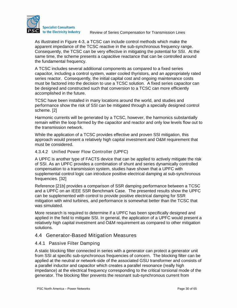
Figure 4-3 - TCSC impedance characteristic with SVR. Source: [2]
Review of Series Compensation for Transmission Lines
PSC North America – Power Networks Page 30 of 65
As illustrated in Figure 4-3, a TCSC can include control methods which make theapparent impedance of the TCSC reactive in the sub-synchronous frequency range.Consequently, the TCSC can be very effective in mitigating the potential for SSI. At thesame time, the scheme presents a capacitive reactance that can be controlled aroundthe fundamental frequency.
A TCSC includes several additional components as compared to a fixed seriescapacitor, including a control system, water cooled thyristors, and an appropriately ratedseries reactor. Consequently, the initial capital cost and ongoing maintenance costsmust be factored into the decision to use a TCSC solution. A fixed series capacitor canbe designed and constructed such that conversion to a TCSC can more efficientlyaccomplished in the future.
TCSC have been installed in many locations around the world, and studies andperformance show the risk of SSI can be mitigated through a specially designed controlscheme. [2]
Harmonic currents will be generated by a TCSC, however, the harmonics substantiallyremain within the loop formed by the capacitor and reactor and only low levels flow out tothe transmission network.
While the application of a TCSC provides effective and proven SSI mitigation, thisapproach would present a relatively high capital investment and O&M requirement thatmust be considered.
4.3.4.2 Unified Power Flow Controller (UPFC)
A UPFC is another type of FACTS device that can be applied to actively mitigate the riskof SSI. As an UPFC provides a combination of shunt and series dynamically controlledcompensation to a transmission system, studies have shown that a UPFC withsupplemental control logic can introduce positive electrical damping at sub-synchronousfrequencies. [32]
Reference [21b] provides a comparison of SSR damping performance between a TCSCand a UPFC on an IEEE SSR Benchmark Case. The presented results show the UPFCcan be supplemented with control to provide positive electrical damping for SSRmitigation with wind turbines, and performance is somewhat better than the TCSC thatwas simulated.
More research is required to determine if a UPFC has been specifically designed andapplied in the field to mitigate SSI. In general, the application of a UPFC would present arelatively high capital investment and O&M requirement as compared to other mitigationsolutions.
4.4 Generator-Based Mitigation Measures
4.4.1 Passive Filter Damping
A static blocking filter connected in series with a generator can protect a generator unitfrom SSI at specific sub-synchronous frequencies of concern. The blocking filter can beapplied at the neutral or network-side of the associated GSU transformer and consists ofa parallel inductor and capacitor which creates a parallel resonance (really highimpedance) at the electrical frequency corresponding to the critical torsional mode of thegenerator. The blocking filter prevents the resonant sub-synchronous current from

Review of Series Compensation for Transmission Lines
PSC North America – Power Networks Page 31 of 65
entering the generator stator to effectively mitigate the potential for SSR-TI and SSR-TA.The design is independent of the current and future network conditions. Reference [13]states that this form of passive filter protection was installed at the Navajo GenerationStation in Arizona in 1976.
Component ratings, de-tuning impacts, and maintenance considerations would need tobe considered to optimize the appropriate design.
4.4.2 Active Filter Damping
Active filters at the generator side of the generator step-up transformer or at the point ofinterconnection can be effective at controlling SSI. Shunt devices can be more practicalas they don’t have to be rated to carry the rated current of the generator as would berequired in a series filter application. An active shunt device used solely for SSI dampingpurposes only has to be rated to counteract the highest initial expected levels of sub-synchronous current through the generator.
Active shunt filters can include thyristor-controlled reactors (TCR) much like an SVC,thyristor-controlled resistors, or a STATCOM. With generator speed as the control input,an active shunt filter can be effective in damping torsional oscillations within thebandwidth of control no matter what the form of SSI. In addition, an electrical side controlinput signal can provide the feedback needed to dampen purely electrical sideoscillations such as IGE or SSCI. Other advantages of active filtering are: detuning isnot a concern; and it is substantially immune to network changes including the levelseries compensation.
STATCOMs and VSCs have been studied extensively in regard to SSI mitigation,including the mitigation of SSCI in wind turbines. In some cases, it has been shown thatthe device may be used in combination with other mitigation measures to provideincreased positive electrical damping at the local generator(s). [39]
4.4.3 Supplementary Excitation Control Damping
Supplementary Excitation Control Damping (SECD) modulates the synchronousgenerator excitation voltage to dampen torsional oscillations. It can be implementedthrough the fast active voltage regulator (AVR) and/or a Power System Stabilizer usingan input signal derived from the shaft speed.
Industry literature presents extensive research and efforts to demonstrate the use forexcitation control to dampen SSI since the 1970s. More recently, advanced non-linearcontrol techniques have been studied considering different types of excitation systemsand PSS with regard to SSR-TI damping characteristics. [37] SECD can be a costeffective solution to mitigating SSR-TI as no new significant high voltage equipment isrequired. [15]
This method of control is not practical for all types of exciters, as the time constants ofexciters are critical to performance. Rotating exciters generally have effective timeconstants that are too large for the control of signals in the sub-synchronous frequencyrange. The power rating and location of the exciter on the shaft must also be consideredin the possible implementation of SECD.
In should be noted that the presence of a PSS may inherently contribute negativeelectrical damping at sub-synchronous frequencies, which can exacerbate an SSI
Review of Series Compensation for Transmission Lines
PSC North America – Power Networks Page 32 of 65
condition. [47] Consequently, care must be taken to properly include the representationof existing PSS in any SSI evaluation.
Our research findings indicate that SEDC has been successfully applied together withTSR protection on the Shangdu steam turbine-generation plant in China [15], however,more research is recommended to determine if this SSI countermeasure has beensuccessfully applied in the US. In general, it appears that SEDC may be practical toincrease positive electrical damping of SSI when applied in conjunction with othermitigation measures such a specifically designed FACT device or when the risk of SSI ismarginal.
4.4.4 Wind Turbine Control Damping
The use of doubly-fed (DFIG) and direct connected induction wind turbines is becomingmore prevalent in the industry. The benefits of these variable speed wind turbinesinclude improved power efficiency and control of reactive power exchange with the ACsystem. Both of these types of wind turbines use voltage source converters (VSC) asthe basis for the variable speed drive and reactive power control.
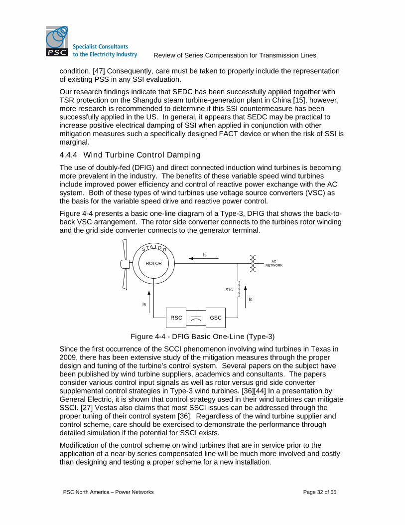
Figure 4-4 presents a basic one-line diagram of a Type-3, DFIG that shows the back-to-back VSC arrangement. The rotor side converter connects to the turbines rotor windingand the grid side converter connects to the generator terminal.
ROTOR
SAT O R
T
RSC GSC
IR
IS
IG
XTG
ACNETWORK
Figure 4-4 - DFIG Basic One-Line (Type-3)
Since the first occurrence of the SCCI phenomenon involving wind turbines in Texas in2009, there has been extensive study of the mitigation measures through the properdesign and tuning of the turbine’s control system. Several papers on the subject havebeen published by wind turbine suppliers, academics and consultants. The papersconsider various control input signals as well as rotor versus grid side convertersupplemental control strategies in Type-3 wind turbines. [36][44] In a presentation byGeneral Electric, it is shown that control strategy used in their wind turbines can mitigateSSCI. [27] Vestas also claims that most SSCI issues can be addressed through theproper tuning of their control system [36]. Regardless of the wind turbine supplier andcontrol scheme, care should be exercised to demonstrate the performance throughdetailed simulation if the potential for SSCI exists.
Modification of the control scheme on wind turbines that are in service prior to theapplication of a near-by series compensated line will be much more involved and costlythan designing and testing a proper scheme for a new installation.

Review of Series Compensation for Transmission Lines
PSC North America – Power Networks Page 33 of 65
4.5 Network-Based Protection Measure
4.5.1 Series Capacitor By-pass
A protection to by-pass the capacitor can be implemented upon the detection ofsustained or growing sub-synchronous currents through the element. This would quicklychange the resonant state of the network to cease the SSO. The drawback of thismethod is that permanently bypassing the series capacitor will reduce the dynamicstability of the network and thus generation may have to be tripped concurrently.
4.6 Generator-Based Protection Measures
4.6.1 SSI Relays
Relay protection can be applied to a specific generator or group of generators to protectthe unit(s) from damage due to an SSI condition. Typically, the relays are set to trip thegenerator unit(s) based on a level and duration of the SSI. This type of protection issometimes applied as back-up to SSI mitigation measures. These types of relays wereinitially developed in the 1970 timeframe in response to the first occurrence of SSR-TIevents. More recently, relay manufacturers have researched and developed solid-state,micro-processor relays for the purpose of SSI protection. The following table presents asummary of generator-based SSI relay types currently available in the industry: [45]
Relay Signal Input Comments
TorsionalMotion (Stress)Relay
Shaft Speed Developed and applied in the late 1970s. Speed isprocessed by band-pass filters to calculateconditions at particular sub-synchronousfrequencies of interest. Torsional Stress Relays(TSR) have been applied at several generatorunits and are still available. Newer torsionalmotion relays are micro-processor based.
S. CaliforniaEdison patent
Terminalvoltage
Micro-processor relay that uses exclusive time-domain analysis on wave parameters ofsuccessive half cycles. More research isrecommended as to the application of this 1986patent, performance information, and currentstatus.
ABB ResearchLtd. patent
Generatorterminalvoltage
Micro-processor based relay developed in the2011 timeframe.
ERLPhasePowerTechnologies
Generatorterminalvoltage andcurrents
Micro-processor based relay is used to performfrequency spectrum analysis on the inputs tocompare sub-synchronous frequency componentswith fundamental component.

Review of Series Compensation for Transmission Lines
PSC North America – Power Networks Page 34 of 65
RelayApplicationInnovation
Armaturecurrent
Micro-processor based relay. Developed in late2009 and applied in 2010 by AEPSC at twolocations as backup generator protection.
The torsional stress relay (TSR) appears to be the most widely applied measure toprotect generators from the potential of SSI due to the proximity of HVDC converters orseries compensated lines.
The input to a TSR is shaft speed measured by magnetic pickups at toothed wheelsinstalled on the turbine and generator end of the shaft. The shaft speed measurementsare evaluated for indications of torsional oscillations at the critical mechanicalfrequencies of interest. A TSR relay can have programmable settings for the criticalfrequencies and magnitude/duration of oscillations to issue actions such as a warning,alarm or trip. Some TSR relays have a built in event and signal recorder to aid in faulttracing. In addition to shaft speed, a TSR would need electrical inputs to be effective forprotection of IGE or SSCI since these forms of SSI do not involve the mechanicalaspects of the generator and can’t be detected from shaft speed.
A generator outage would be required to install and commission a TSR and there isalways risk of mis-operation of a TSR that could result in an undesired generator outage.Information of generator stress versus cycles to failure is required to properly set therelays.
Our research indicates that TSR relays have been applied on several generating units,primarily to protect against the possible occurrence of SSTI since the late 1970s.However, detailed performance information and operations and maintenance experiencewith TSR relays was not found to be readily available.
In response to the recent SSCI phenomenon, relay manufactures have proposed anddeveloped new SSI protection based on high speed signal measuring, advancedfiltering, and fast processing with micro-processor based relays using electrical quantityinputs. Oscillations in an SSCI event can develop very rapidly which imposes therequirement for a very fast detection scheme. [20] The filtering and signal processing forthe older generation of SSI relays introduce a long time delay which makes these relaysless reliable or even ineffective for SSCI protection.

Review of Series Compensation for Transmission Lines
PSC North America – Power Networks Page 35 of 65
5 Protection Schemes and Protection Relay Considerations
5.1 Key Section References
For gaining more in-depth knowledge on the subject matter in this Section 5, thefollowing primary references are suggested:
[3] ABB. (2012). “Series Compensated Line Protection”. ABB Webinar.http://www.youtube.com/watch?v=rKWnMyTYUDM
[10] Altuve, Mooney and Alexander. (2008). “Advances in Series-CompensatedTransmission Lines”. TP6340-01, Schweitzer Engineering Laboratories, Inc.
[11] Anderson and Farmer. (1996). “Series Compensation of Power Systems”.Encinitas, CA: PBLSH, Inc.
[22] IEEE. (2007). “IEEE Guide for Protective Relay Application to Transmission-LineSeries Capacitor Banks”, IEEE Power Engineer Society – Power Systems RelayingCommittee, Std C37:116-2007
[26] Kasztenny. (2001). “Distance Protection of Series-compensated Lines: Problemsand Solutions”. GER-3998: GE Power Management
[43] Wilkinson. “Series Compensated Line Protection Issues”. GER-3972: GE PowerManagement
Additional subject references are indicated in square brackets throughout the sectionwith the complete paper reference list presented in Section 8
5.2 General
Series compensation may be installed in the middle of a transmission line or at one orboth ends. In general, there are more protective relay complexities when the seriescapacitor is installed at the line end(s). Of course, if series compensation is initiallyinstalled in the middle of a transmission line the addition of a new substation within theline may increase the protection complexities - therefore it is important to understand theline end issues as will be highlighted in this section.
The addition of series compensation within a transmission line presents complexitieswith regards to the relay protection of the line itself, and in many cases the relayprotection of adjacent and parallel lines. These complexities will be a function of:
system configuration,
level of series compensation,
series capacitor protection and control schemes, and
other factors.
The application of series compensation first occurred in the 1950s in the US, and theuse of series compensation is becoming more prevalent, so fortunately there is sufficientindustry experience and knowledge available with regard to associated protection issuesand solutions. If the complexities are well understood, relay protection systems can bereliably designed, tested and applied, especially through the use of modern relaytechnologies. [43]

Review of Series Compensation for Transmission Lines
PSC North America – Power Networks Page 36 of 65
This section begins by describing the unique system protection issues associated withthe introduction of transmission line series compensation. It then describes theadvanced relays and schemes that can be applied to address the issues described.Lastly, case examples which present philosophies and experience with the protection ofseries compensated transmission lines from three utilities are summarized.
5.3 Influence of Capacitor Protection
Modern series capacitors are protected by a parallel metal oxide varistor (MOV) asillustrated in Figure 5-1. The MOV limits the voltage across the capacitor based on itsrated protective level. For transient conditions, the MOV will conduct to absorb energyas necessary to limit the periodic overvoltages across the capacitor. When the MOVconducts, the apparent series impedance of the parallel elements changes in a non-linear manner as the MOV has non-linear resistive characteristics. The protectivevoltage level of the MOV is selected based on normal conditions, system power swingconditions and anticipated overload conditions. [29]
Series Capacitor
Bypass Switch
MOV
VSC
Figure 5-1 - MOV protected series capacitor
The MOV is also protected by a bypass switch which is triggered based on its ratedenergy dissipation level. When this switch operates, both the MOV and the seriescapacitor are bypassed until the energy level decreases below the desired setting.
For most faults that result in high currents through the series capacitor, the MOV-basedprotection will bypass the series capacitor and impedance relays will see the linetransmission line impedance only. For high impedance line-ground faults however, thecurrent may not be sufficient to trigger the bypass switch and the capacitive reactancewill influence the apparent impedance seen by impedance distance relays. For single-phase faults, only the MOV protection on the faulted phase may function, while thecapacitors on the un-faulted phases will not be circumvented. Consequently, the MOVprotection can greatly influence the apparent impedance seen by impedance relays andthis must be carefully considered in the relay protection system design. High impedancefaults as well as faults under minimum generation conditions should be evaluated as partthe relay system design and evaluation. [10][29]
5.3.1 Voltage Inversion and Current Inversion
Faults electrically close to series capacitors can lead to voltage and or current inversionswhere the phase angle changes by 180 degrees. [3][10][26]
When the impedance between a relay and a fault is capacitive, the local voltage at therelay may invert depending on the relative magnitude of other system impedances. Thediagram in Figure 5-2 presents a fault condition on a series compensated line between

Review of Series Compensation for Transmission Lines
PSC North America – Power Networks Page 37 of 65
Bus B and Bus REMOTE, where voltage inversion will occur across the series capacitor;VB is 180 degrees out of phase from VC. For this particular voltage inversion conditionto occur the Xc impedance conditions listed must hold true. If the line has impedance (ordistance) protection, then if the relay uses Bus B for the voltage input, the relay wouldsense the fault as a reverse fault rather than an actual forward fault, and may fail tooperate. However if point C was used as the voltage input then the forward fault wouldbe correctly detected. As shown, the voltage at Bus B is reversed and remains reversedas you move toward the source until you reach Point A. If a new bus were to be added inthis segment in the future, voltage reversal would be a concern at this bus as well as atBus B.
XS
SOURCE
BXL1 XC XL2
REMOTE
XRA C
VS VR
VA
VB
VC
VF
kXL2
XC > kXL2
XC < XS + XL1 + kXL2
Figure 5-2 - Voltage profile for a line side fault near a series capacitor (ForwardFault)
Figure 5-3 shows a voltage profile for a fault on a line behind a series compensatedtransmission line. For the impedance conditions listed, the voltages on either side of thecapacitor will again be 180 degrees out of phase. If an impedance relay protecting theseries compensated line at Bus B uses the line side voltage (Point C), under thiscondition the voltage will reverse and the apparent impedance will indicate a forwardfault rather than an actual reverse fault, and mis-operation may result. Conversely, if theBus B voltage was used then the relay would correctly register the fault in the reversedirection.
XS
SOURCE
BXL1 XC XL2
REMOTE
XRC
VS VR
VF
VB
VC
gXL2
XC > gXL1
XC < XR + XL2 + gXL1
Figure 5-3 - Voltage profile for an adjacent line side fault near a series capacitor(Reverse Fault)

Review of Series Compensation for Transmission Lines
PSC North America – Power Networks Page 38 of 65
The simple voltage inversion examples presented above are based on three phasefaults and positive sequence impedance. Similar voltage reversal conditions can affectthe directional discrimination of both negative and zero sequence relays. Refer toReference [10] for supporting explanation and examples.
When the impedance on one side of the line fault is inductive and the other side of a linefault is capacitive a current inversion can occur. This condition is illustrated in Figure 5-4.As shown the current from one end of the line is 180 degrees out of phase from thecurrent of the other side of the series compensated line. This current inversion conditionis opposite of the condition that defines an internal fault on an uncompensated line asone appears as an in-feed and the other as an out-feed.
There are also system conditions that may result in the current being indeterminate atone end during an internal fault. The same current reversal issues can occur with thenegative and zero sequence currents if Xc is larger than the negative sequence sourceimpedance or zero sequence source impedance, respectively. [10]
XS
SOURCE
XC XL
REMOTE
XR
IS XC > XS
VS
VR
IR
IS IR
Figure 5-4 - Example of current reversal condition in a SC line
Current inversion and indeterminate current conditions can affect the desired operationof distance, phase comparison, and directional elements of protection relays. [10]
5.3.2 Distance Protection – Measured Impedance
Special considerations have to be made when applying distance protection on a seriescompensated line as explained in this section and in Section 5.3.3.
Distance relay impedance characteristics (blue circles) shown in Figure 5-5 areassociated with the protection of a mid-point series compensated transmission line. Theapparent impedance seen by the relay is much less if the series capacitor remains in-service, as opposed to if the capacitor is by-passed. If the Zone 1 mho relay is set forthe condition of the series capacitor by-passed (dashed circle), it can overreach beyondthe end of the line and potentially trip the line inadvertently for an external fault condition.Depending on the level of series compensation, the Zone 1 reach would have to bereduced well below the typical 80-90% reach used to protect an un-compensated line.[10]

Review of Series Compensation for Transmission Lines
PSC North America – Power Networks Page 39 of 65
X
RA
B
B
-jXC
ZL
Figure 5-5 - Impedance protection on a mid-point SC line
The example above explains the measured impedance difference for the two systemstates with and without the series capacitor by-passed. This issue gets furthercompounded with the dynamic and non-linear characteristics of the MOV when theelement is triggered and is not in the by-passed state.
The location of the series capacitor and the degree of compensation will impact themeasured apparent impedance. For a close-in fault to the series capacitor, the netreactance seen by a distance relay could be capacitive. In such a case, a standardimpedance relay would sense that the fault was in the reverse direction, leading topotential mis-operation. Thus, series capacitors located at the line end can also effectdirectional discrimination in addition to the measured impedance. [10][26]
5.3.3 Sub-synchronous Transient Signal Impacts
As explained previously in Section 3.2.1, the application of series compensation within apower system introduces new electrical resonance conditions at sub-synchronousfrequencies. When faults and switching operations occur in the vicinity of seriescompensation, transient electrical system oscillations at sub-synchronous frequency willbe imposed on the fundamental frequency response. The magnitude and number ofsub-synchronous transients will depend on the degree and number of seriescompensated transmission lines in service and the operation of the protection functionassociated with each series capacitor. The transient response of the power system dueto large disturbances can adversely impact the operation of protective relay systems onthe series compensation line and potentially on adjacent lines. The input signal filterresponse of protective relays should be appropriately considered. [26]
Figure 5-6 illustrates a transmission line that is compensated on the remote end. For afault at the remote end past the series capacitor, the capacitor’s reactance in seriescombination with the line’s inductance will produce a sub-synchronous transient.Considering that this transient response will be at a frequency less than the fundamentalfrequency as explained in the previous paragraph, the lines inductance will appear lessand the capacitance of the will be higher. This will result in a higher transient voltagedrop across the capacitor and the line will appear to have a higher compensation levelduring the transient period from the perspective of a distance relay at the sending end ofthe line. [26] This can result in mis-operation of the distance relay for faults beyond theline end series capacitor as further explained below.

Review of Series Compensation for Transmission Lines
PSC North America – Power Networks Page 40 of 65
XLXC
FAULT
Figure 5-6 - Transmission line with remote line end SC
The apparent impedance seen by a Zone 1 distance relay at the sending end of the lineis shown in Figure 5-7 by the red arrowed trace along with the zone 1 characteristic asthe blue circle.
The apparent impedance (red trace) changes over several cycles due to the transientresponse superimposed on the line from the fault. In this case, it is assumed that thereis some resistance in the system to dampen the transient response. The apparentimpedance initially appears less due to the transient response, so the relay sees theimpedance entering the Zone 1 trip region (blue circle). The outcome is that the relaycould erroneously trip the local end for faults which are actually beyond the Zone 1intended reach, or potentially beyond the remote end itself, and may lead to coordinationissues with other protection schemes.
It may be possible to alleviate this problem by further reducing the reach (reducediameter of the blue circle to below the red apparent impedance trace) and/or byintroducing a Zone 1 time delay to allow time for the transient to move out of the bluecircle before the relay initiates a trip. In either case, the consequence for coordinationwith other protections would have to be carefully studied.
X
RA
Figure 5-7 - Distance relay overreach due to sub-synchronous transient signals
Sub-synchronous transients will also occur after a fault is cleared if the series capacitorMOV stops conducting and the series capacitor is effectively re-inserted into thenetwork. These transients may adversely impact relay operation and thus they must alsobe considered.
5.3.4 Adjacent Line Protection Impacts
When series compensation is added to a transmission line, attention must be paid to theprotection of adjacent transmission lines in addition to the protection on the series

Review of Series Compensation for Transmission Lines
PSC North America – Power Networks Page 41 of 65
compensated line itself. This is particularly true for line end applications of seriescompensation. Distance relays on adjacent lines can be influenced by the negativereactance characteristic of the series capacitor. [10]
The dotted circle in Figure 5-8 below depicts a Zone 1 relay on an adjacent line to a localend series compensated transmission line. As shown as standard distance relay wouldincorrectly operate for line faults on the series compensated line that are close-in to thecapacitor.
X
RA
B
B
A’-jXC
Figure 5-8 - Zone 1 distance relay on SC line (solid) and adjacent line (dotted)
If the adjacent lines are short and the line reactance is less than the capacitor reactance,the concern gets extended to the remote bus as well as the local bus of the adjacentline; two or more line sections away. [3]
5.3.5 Other Impacts
Series capacitors can exacerbate relaying issues associated with un-transposed linesand zero sequence mutual impedance between parallel lines. Since the addition of aseries capacitor effectively lowers the line balanced self-impedance, any unbalanced lineimpedance and mutual impedance will become more pronounced with increased seriescompensation. [26]
Series compensation provides for higher steady-state power flows in the power systemand the increase in load current can impact the sensitivity setting of protective relays.
5.3.6 Automatic Reclosing for Series Compensated Transmission Lines
Automatic reclosing strategies may be used in conjunction with series compensatedtransmission lines. The relay protection complexities presented within this paper mustbe factored into an automatic reclosing design strategy. Furthermore, the scheme mustbe properly coordinated with the series capacitor control and protection.
Based on the system requirements, either three-phase reclosing or single-phasereclosing may be appropriate. The primary advantage of for single-phase reclosing is tomaintain the healthy two phases to maintain some level of power transfer to enhancesystem stability.
The series compensated case studies summarized in Section 5.5 address the generalautomatic reclosing philosophies applied by the corresponding transmission owner. Forexample, BC Hydro does not switch their series capacitors as part of the transmission
Review of Series Compensation for Transmission Lines
PSC North America – Power Networks Page 42 of 65
line; rather the series capacitor is switched separately but in coordination with thetransmission line switching sequence. [33]
Definitions used in this Section 5.3.6 include:
SPT/SPR – Single-pole tripping and single-pole reclosing
3PT/3PR – Three-pole tripping and three-pole reclosing
5.3.6.1 Series Capacitor Switching
When designing the automatic reclosing philosophy and practice for a seriescompensated transmission line, consideration should be made for whether the capacitoris to be switched as part of the transmission line, or if the capacitor will be separatelyswitched. In the latter case, the capacitor switching must be carefully coordinated withthe transmission line protections and switching. Benefits associated with separatelyswitching the series capacitor include:
1. Minimizing transmission line circuit breaker transient recovery voltage (TRV) dutyrequirements,
2. Reducing the series capacitor MOV capacity requirements,
3. Mitigating dc current component in transmission line shunt reactors,
4. Mitigating low-frequency transients and the possibility of SSR-TA with nearbygenerators during reclosing,
5. Reducing the secondary short circuit arc by increasing the network impedanceduring reclose dead time (for SPT/SPR schemes only). [22]
If by-passing the series capacitor is required to keep the TRV duty within the rating of thetransmission line circuit breakers, the by-pass operation would need to occur prior to theline breakers opening.
The series capacitor switching logic and coordination can be accomplished by usinglocal current and voltage signals. Zero sequence mutual coupling from unbalancedfaults on parallel lines should be analyzed to prevent undesired operation of the seriescapacitor switching logic. Alternatively, signals can be communicated from thetransmission line terminals to properly operate and time the series capacitor by-pass andre-insertion. The speed and reliability of the communication channels needs to befactored into the design. [22]
The benefits listed in this Section apply to the switching of series capacitors during lineenergization as well as to automatic reclosing.
5.3.6.2 Three-phase Automatic Reclosing (3PT/3PR)
Coordination of 3PT/3PR is more straightforward than using single-pole reclosing on aseries compensated transmission line. If it is decided to implement only 3PT/3PR on aseries compensated line, both the line protection switching, and capacitor protection andswitching should be done on the three-phase basis. The reclosing scheme should becarefully tested using an EMT-type simulation program to assess breaker duties,transient effects, dependability and security of local and adjacent line relaying, andcoordination with any series capacitor protections and enabled switching schemes.

Review of Series Compensation for Transmission Lines
PSC North America – Power Networks Page 43 of 65
5.3.6.3 Single-phase Automatic Reclosing (SPT/SPR)
System stability may be improved by employing a SPT/SPR scheme on a critical seriescompensation transmission line. Furthermore, it may be beneficial to leave the seriescapacitors of the healthy two phases in service to maximize the transfer capacitor duringthe SPT/SPR interval.
It is important that the series capacitor protection is properly coordinated with theSPT/SPR scheme such that no three-phase capacitor switching is triggered during theautomatic reclosing sequence.
Rapid and precise phase selection is required for SPT. With series compensatedtransmission lines, phase selection can be more complex due to possible current andvoltage signal inversions for high impedance faults, so proper relays and phase selectionmethods must be applied and tested. Furthermore, low frequency transients associatedwith series compensated lines can introduce errors in the signals measured by therelays. With advanced relays and high-speed, multi-channel communications for PILOT-aided schemes, these complexities can be overcome. [43]
5.3.6.4 Spurious By-pass Operation
There is the possibility of spurious operation of series capacitor protection due to certainexternal faults. If the series capacitor protection results in a single phase by-pass/re-insertion, it can be problematic for the transmission line protection on the seriescompensated line. This circumstance is more prevalent when directional-basedcomparison schemes are utilized with sensitive ground fault protective elements, asundesired tripping may occur. [33]
5.4 Relay Protection Solutions
5.4.1 Advanced Relays for Series Compensation Application
Protective relays have advanced for the special purpose of protecting seriescompensated transmission networks. Modern relays and systems have been devisedand proven to enhance the reliability of distance, directional, and differential basedprotection of series compensated networks. The relays described below aresubstantially based on documentation produced by two vendors; Schweitzer andGeneral Electric. Other vendors may offer variations or other advanced relays for theprotection of series compensated lines that are not covered in this summary.
5.4.1.1 Memory Polarization
Standard distance relays are self-polarized through the typical use of positive sequencevoltage or un-faulted phase voltages. Use of these quantities for polarization may leadto relay mis-operation in the case of voltage inversion or close-in three-phase faultswhere the relay input voltage is very low.
Modern distance relays provide the capability to use memory polarization with multi-inputcomparators to enhance relay pickup and fault directional recognition. Memorypolarization uses a time-dependent combination of pre-fault and post-fault voltageconditions when this feature is enabled in a relay. The time-dependent memory functionis used to phase out the pre-fault information with time to position the relay for properoperation in response to situations such as system swings or line switching into a fault.[10][26]

Review of Series Compensation for Transmission Lines
PSC North America – Power Networks Page 44 of 65
In series compensated networks, the duration of the polarization memory should be setfor proper relay pickup with consideration of the series capacitor MOV protectionresponse, and the slowest fault clearing time. [10]
5.4.1.2 Special Series Compensation Logic
Over the many years of developing and testing protection systems for seriescompensated lines, special logic has been incorporated to improve overreach in Zone 1of distance relays. Through the proper setting of the special logic, the relay can detectwhen a fault is beyond the series capacitor and block the operation to preventoverreach. If the fault is between the relay and the series capacitor, the relay willcorrectly operate. This is accomplished through the comparison of a measured voltagewith a calculated voltage by the relay. The special logic requires the capacitivereactance to be specified as part of the setting, with the appropriate sign based on thevalue measured by the relay. With the relay logic and careful setting, correct directionalsensing will be accomplished regardless of the location of the voltage transformer inrelation to the series capacitor. The zone 1 reach is set based on the uncompensatedtransmission line impedance. [10]
5.4.1.3 Sequence Component Impedance for Directional Discrimination
Relays that use negative or zero sequence component inputs provide superiordirectional discrimination for single-phase faults. When analyzing the apparentimpedance with negative sequence quantities for example, there is generally sufficientmargin in the calculated apparent impedance between forward and reverse faultconditions and the sign of the apparent impedance is opposite depending on the faultsdirection. Proper settings in these relays provide correct directional discrimination evenwith the possibility of voltage reversal. [10][26]
5.4.2 Protection Schemes
5.4.2.1 Line Current Differential Protection
Line current differential schemes can be a very good choice for protection of seriescompensated transmission lines. Some of the advantages of this scheme include:
Immunity to voltage inversion
No impact due to series capacitor protection (i.e., MOV operation)
The location of the associated potential transformers is not a concern
The sub-synchronous transients may influence the operational time of differentialelement so the relay’s filter response should be understood. As series compensatedlines may be very highly loaded, load flow impacts should be reflected in the design,setting selections, and testing.
Reference [10] suggests the use of Alpha Plane differential elements to accommodatethe potential for current inversion and sub-synchronous transients. The use of anegative sequence differential scheme in parallel with the positive sequence schememay also be used to contend with current inversion and ensure correct operation.
A reliable communications path between line end relays is required as the schemerequires a precise measurement and comparison of current signals from each end.
Review of Series Compensation for Transmission Lines
PSC North America – Power Networks Page 45 of 65
Improvements in communications and signal conditioning techniques has enhanced thesecurity of differential scheme performance.
5.4.2.2 Directional Comparison Protection
Directional comparison can provide a secure and reliable protection system for seriescompensated lines with the application of the advanced relays such as thosesummarized previously in this Section 5.4, and through careful consideration of the relaycomplexities discussed herein.
Directional comparison schemes should be equipped with blocking units and transientblocking circuits to eliminate the possibility of false tripping due to CT saturation andtransient blocking logic may be necessary for situations where directional integritycannot be maintained for slow clearing faults. [10][26][43]
In contrast to a line current differential scheme, variations in signal communication timecan be easily accommodated though use of a time delay greater than the maximumcommunication time. Furthermore, a directional comparison scheme is comparingdiscrete relay signals rather than instantaneous current phasor signals, so it can againbe easier to make adjustments to optimize dependability and security. [43]
Permissive Overreach Scheme
A permissive overreach scheme can provide secure protection of a series compensatedline. The reach of the schemes distance devices should cover the condition where theseries capacitor is by-passed by its overvoltage protection (i.e., the uncompensated lineimpedance). The drawback to this is that the relays will have a high degree of overreachwhen the series capacitor is not by-passed and this presents more potential for mis-operation during external faults. [10][26]
Underreaching Direct Trip and Direct Transfer Trip Scheme
As series compensated lines are often very long, direct trip schemes are frequentlyadded to supplement a differential or directional comparison scheme to provide anenhanced level of security.
As presented in Section 5.3.1, current reversal is possible in series compensated lines,and this can be an issue for directional comparison protection schemes. For faults atone end of the line, the current at the other end can be indeterminate or reverseddepending on network impedances. This condition causes permissive overreachschemes to be less reliable for line end fault as compared to faults near the middle of theline.
In series compensated lines, a direct transfer trip scheme using underreaching relaysettings can be used to provide dependable protection for near end line faults. Thus, adirect transfer trip scheme together with a permissive overreach scheme can greatlyenhance the dependability of the overall protection system.
5.4.3 Protection Design and Performance Verification
Design and testing protective relaying schemes for and in the vicinity of a seriescompensated transmission line with detailed models of the transmission network and keycomponents is essential. Digital simulation of relay performance using an electro-magnetic transient program (EMT-Type) or real time digital simulator (RTDS) is

Review of Series Compensation for Transmission Lines
PSC North America – Power Networks Page 46 of 65
recommended to ensure a secure and dependable relay protection design. A steady-state short circuit program will not reflect transients due to series compensation.
Detailed electromagnetic transient simulation is required to produce the sub-synchronous transients that will be associated with series compensation in the networkand determine impacts to the relay system performance. Other important modelingrequirements include detailed representation of:
The non-linear MOV characteristics for the series capacitor protection andreinsertion control
Relay performance
Potential transformer or CCVT transient response
Frequency dependency of the local transmission lines and transformers
Automatic reclosing controls
Various system conditions should be analyzed with a combination of fault location andfault types. It is important to apply ground faults with low and high resistance as thismay influence the operation the series capacitor protection, which in turn, can impact therelay system response. Variation of the fault inception angle is also recommended toproduce different dc transients and different levels of sub-synchronous frequencytransients. [10][18]
The use of an RTDS program will go one step further in the performance verification asactual relays can be connected directly to the simulator.
5.5 Protection Case Studies
5.5.1 BC Hydro
Source
Protection of EHV Transmission Lines with Series Compensation: BC Hydro’s LessonsLearned [33]
Summary
Protection challenges with regard to series compensation of BC Hydro’s 500 kVtransmission network included:
Undesired operation of fault direction and detection elements:
o Zone 1 overreach
o Voltage inversion
o Current inversion
Influences of unbalanced currents caused by single pole switching (SPS) or linetripping (SPT) and reclosing (SPR).
Series capacitor switching.
Sub-synchronous transient impacts on relay operation.
Review of Series Compensation for Transmission Lines
PSC North America – Power Networks Page 47 of 65
The paper focuses on capacitor switching issues during line faults and routine lineenergization.
Issues magnified by the addition of series compensation in the BC Hydro systeminclude:
Unequal line transpositions.
Unequal transmission line lengths per phase (adjacent cable circuit).
Transmission line single pole open (SPO) conditions.
Protection Scheme
BC Hydro uses identical primary and standby systems with minor setting differences(dual primary systems). They claim this arrangement provides the benefit of increasedsecurity and lower costs.
Permissive overreaching transfer trip (POTT) with echo logic is used on all 500 kVtransmission lines. Residual and negative-sequence directional overcurrent elementsare used as part of the POTT. Phase-segregated direct transfer trip (DTT) is alsoapplied to improve selectivity and lower operating time for certain single-phase faults.Time-overcurrent ground relays are used for backup ground fault protection.
The paper presents their approach for setting the negative-sequence directionalovercurrent element to minimize the chance for mis-operation based on lessons learnedfrom actual studies and application. The suggested approach is to:
Set considering the minimum Z2 source for forward and reverse faults, as well asthe line Z2 and setting the elements to half of this total impedance. This methodis recommended when the system impedances are dissimilar at each lineterminal. An appendix in the reference paper discusses the pros and cons to thisapproach over the method recommended by the rely manufacturer for BCHydro’s applications.
BC Hydro addresses the impact of security of negative-sequence directional elementoperation due to non-transposed circuits by appropriately adjusting the unbalanced-to-balanced current ratio factors, and forward and reverse negative sequence impedancesettings accordingly.
Auto-reclosing challenges
BC Hydro has multiple modes of protection, and the normally operated mode is:
SPT/SPR for single line to ground faults
Three pole tripping/reclosing (3PT/3PR) for multi-phase faults
The interval between SPT/SPR operations appears as an internal fault to a POTTscheme. When incorporating sensitive operation for high impedance ground faults,certain elements must be temporarily disabled to avoid undesired operation. Foruncompensated lines, a time delay of 6 cycles is used to mitigate undesired operation ofthe ground elements. For a series compensated line, an extended time delay wasrequired (12 cycles) to accommodate single pole capacitor switching (see next section).Alternatively, BC Hydro suggests that digital communications can be used to provide

Review of Series Compensation for Transmission Lines
PSC North America – Power Networks Page 48 of 65
signals from the series capacitor back to the terminal relays to block sensitive elementsduring switching.
Series Capacitor Switching
BC Hydro uses what they claim is a unique switching practice for their seriescompensated transmission lines. Rather than switching the transmission line andassociated series capacitor as a single element, BC Hydro uses the practice ofseparately switching the capacitor when the line is tripped, and then reinserting theseries capacitor after the line is successfully reclosed. For SPT/SPR operations, onlythe effected phase of the series capacitor is switched out/in to maximize the powertransfer through the healthy series compensated phases. The capacitor switching takesplace 6 cycles after the line (or phase) is tripped and is reinserted 10 cycles after the line(or phase) is successfully re-closed.
Protection Scheme Testing and Verification
The BC Hydro paper emphasizes the importance of detailed transient testing forprotective relaying applications through the use of real-time digital simulation thatincorporates the actual micro-processor based relay algorithms. BC Hydro recommendsthat the following be included in the simulation model:
Reclosing controls on adjacent and parallel lines.
Automatic shunt reactor switching controls.
Circuit breaker closing controls and logic.
Series capacitor bypass and automatic reinsertion controls.
Series capacitor protection elements.

Review of Series Compensation for Transmission Lines
PSC North America – Power Networks Page 49 of 65
5.5.2 Hydro-Québec TransÉnergie (HQT)
SourceTransmission Line Protection by Simon Chano - Cover Story PAC World Magazine,Winter, 2008 [14]
SummaryHQT has implemented series compensation into their EHV system since the early 1990’sto increase power transfer capacity. Series compensation levels ranged from 20 to 44%.Extensive system studies were performed to determine the best location to introduceseries compensation and as a result, some lines have the series capacitor installed atone end and others lines have the series capacitor installed at mid line as shown inFigure 5-9.
Figure 5-9 Main and back-up proctection schemes for line end and mid-line SCSource: [33]
Relay Protection ChallengesVoltage reversal issues were addressed primarily through the use of polarized ormemorized voltage based directional elements. Current reversal was not observed dueto the level and location of series compensation together with series capacitor MOVprotections.
Protection SchemesRelay selection and main protection philosophies were developed and implementedbased on extensive real-time simulation testing on HQT’s Transients Network Analyzer(TNA).
Figure 5-9 above shows the Main 1, Main 2 and backup protection arrangements usedto protect HQT’s series compensated lines. As shown, different schemes are usedbased on the location of the series capacitor on the line (i.e., middle or end).

Review of Series Compensation for Transmission Lines
PSC North America – Power Networks Page 50 of 65
The Main 1 and Main 2 schemes are communications dependent whereas the backupscheme does not rely on communications between the line terminals. The integrity ofthe communications channel(s) is very important for the Main’s schemes and as suchdigital fiber-optic based communications are rapidly replacing analog communications inthe HQT system for high-capacity performance and speed.The backup protection uses an impedance based measurement relay. The modifiedimpedance relay incorporates a lens characteristic to avoid sensitivity to load and powerswings. Based on careful selection and testing, the backup impedance relays provedreliable and secure for transient and dynamic effects associated with seriescompensation.
Automatic ReclosingHQT utilizes three-phase automatic reclosing for single phase fault detection/clearing ontheir EHV series compensated transmission lines. The paper did not note any specificissues related to automatic reclosing of series compensated line.
Testing and VerificationHQT indicates that transient simulator testing using a real-time TNA was the mosteffective method to test and verify various relay protection devices and schemes. Thismethod provides for the following complex issues to be effectively analyzed:
Weak in-feed.
Harmonic and sub-harmonic transient effects.
Low frequency current oscillations.
Zero sequence mutual coupling between parallel lines.
Voltage and current reversal conditions.
Shunt reactor and line reclosing switching operations/logic.
Series capacitor control and protection systems.
Varying fault incidence angles.
CT and CVT characteristics.
High resistive faults, evolving faults, and reclosing on a permanent fault.
5.5.3 Pacific Gas & Electric
SourcePG&E 500 kV Series-Compensated Transmission Line Relay Replacement: DesignRequirements and RTDS Testing [18]
SummaryHigh speed protection was designed and implemented to:
Improve system transient stability
Maintain 500 kV system availability
Reduce possible damage to insulators and conductors
Permit high-speed reclosing
Compensate for reduced Zone 1 reach in series compensated lines
Relay Protections Schemes

Review of Series Compensation for Transmission Lines
PSC North America – Power Networks Page 51 of 65
PG&E uses the following main and backup schemes. Sets A, B and C rely oncommunication channels. The backup Set D does not use communications between theterminals.
Relaying ChallengesThe series capacitors introduce the possibility of overreach and undesired operation ofZone 1 distance relays. The options that PG&E considered to mitigate this issueincluded:
Introduce a Zone 1 time delay – this was not recommended
Further reduce Zone 1 reach and verify though RTDS testing
Enable SC logic in to block Zone 1 for fault beyond a series capacitor located infront of the relay
The presentation demonstrates that Zone 1 overreach can occur for faults on adjacentseries compensated lines as well as on a directly protected series compensated line.
The use of advanced relays with series compensation logic and memory polarizationmitigates the possibility of mis-operation due to voltage inversion and overreach.
Automatic ReclosingThe PG&E presentation indicates that both single phase and three phase automaticreclosing is utilized on the series compensated transmission lines.
Testing and VerificationThe presentation strongly advises the use of a RTDS platform with direct connection ofthe relays to test and verify relay protection performance. See Section 5.4.3 of thispaper.

Review of Series Compensation for Transmission Lines
PSC North America – Power Networks Page 52 of 65
6 Project Planning and Implementation Considerations
6.1 Key Section References
For gaining more in-depth knowledge on the subject matter in this Section 6, thefollowing primary references are suggested:
[11] Anderson and Farmer. (1996). “Series Compensation of Power Systems”.Encinitas, CA: PBLSH, Inc.
[48] IEC 60143 ‘Series Capacitors for Power Systems’, Parts 1, 2, and 4
Figure 6-3 and Figure 6-6 are adapted directly from Chapter 4 of [11].
6.2 Location of Series Compensation
The location of series compensation along a transmission line is a critical design factor inselecting to integrate this technology into AC transmission networks. The principalconsiderations in selecting location of series compensation are [11]:
The “effectiveness” of series compensation varies as a function of location alonga transmission line;
The location of series compensation affects the voltage profile along thetransmission line;
Transmission line protection settings and capacitor bank bypass energydissipation specifications depend on the location of the series compensationalong the transmission line;
Future configurations of the transmission lines being compensated; and
Operations and maintenance issues such as site accessibility, land availabilityand telecommunications depend on local conditions where the seriescompensation is installed.
The “effectiveness” of a series capacitance is determined using the distributedparameter theory of transmission lines. It provides a measure of how well the receivingend voltage of a transmission line is maintained depending on the placement of theseries capacitor from the sending end. From the perspective of the effectiveness ofseries compensation, the optimal location for a single series capacitive reactance is atthe mid-point of a transmission line. [11]
The voltage profile of a series compensated line varies according to the location of anyseries capacitor banks and the loading levels of the transmission line. Series capacitorinstallations can be installed mid-line, either a single unit at the mid-point or two unitseach a third of the way along the line, or they can be installed at the line ends with bus-side or line-side shunt reactors. The topologies are shown in Figure 6-4, Figure 6-5,Figure 6-2, and Figure 6-1.
As the The following general observations can be made in regards to the voltage profileof a series compensated line:

Review of Series Compensation for Transmission Lines
PSC North America – Power Networks Page 53 of 65
Voltage varies smoothly along the transmission line and undergoes a stepchange at the capacitor;
The amplitude of the voltage variation across series capacitors increases with thelevel of compensation of the line (the size of the capacitor) and the currentflowing through the capacitor;
For highly loaded lines (above impedance loading), the voltage profile is concaveupwards3;
Lightly loaded lines (below surge impedance loading) are concave downwards4;
Lines loaded to surge impedance loading will generally show a linear voltageprofile along the length of the transmission line;
Increased levels of compensation result in a decrease of the “sag” in the voltagewith a tendency to increase the overall voltage profile;
The voltage variation across a series capacitor is always in the direction thatimproves the voltage profile whatever the loading level;
6.2.1 Mid-Line
This can either consist of a single capacitor bank located halfway along the transmissionline or two installations each located one-third of the length between the two line ends.Multiple installations may be required when the insulation coordination plan for existinglines do not allow for the relatively high voltages just prior to the series capacitor. Mid-line stations are unattended.
XL3 XC
2
XL3
XL3XC
2
Figure 6-1 - Midline compensation at 33% and 66% of line length
XL2
XL2
XC
Figure 6-2 - Mid-line compensation at 50% of line length
3 Concave upwards refers to situations where the tangent to the curve lies below it.4 Concave downwards refers to situations where the tangent to the curve lies above it.

Review of Series Compensation for Transmission Lines
PSC North America – Power Networks Page 54 of 65
Mid-Line, 33%, 66% Mid-Line, 50%
Light Loading(½ x SIL)
150 0
1.00Vo
lta
geM
agn
itu
de
(p.u
.)
Distance from Receiving End (miles)
0.90
1.10
1.20 K=30%K=50%K=70%
300 300 150 0
1.00Vo
lta
geM
agn
itu
de
(p.u
.)
Distance from Receiving End (miles)
0.90
1.10
1.20 K=30%K=50%K=70%
Surge ImpedanceLoading (SIL)
300 150 0
1.00Vo
lta
ge
Ma
gn
itu
de
(p.u
.)
Distance from Receiving End (miles)
0.90
1.10
1.20 K=30%K=50%K=70%
300 150 0
1.00Vo
lta
geM
ag
nit
ud
e(p
.u.)
Distance from Receiving End (miles)
0.90
1.10
1.20 K=30%K=50%K=70%
Heavy Loading(2 x SIL)
150 0
1.00Vo
lta
geM
agn
itu
de
(p.u
.)
Distance from Receiving End (miles)
0.90
1.10
1.20 K=30%K=50%K=70%
300 300 150 0
1.00Vo
lta
ge
Ma
gnit
ud
e(p
.u.)
Distance from Receiving End (miles)
0.90
1.10
1.20 K=30%K=50%K=70%
Figure 6-3 – Line voltage profile for mid-line series compensation. Source [11]

Review of Series Compensation for Transmission Lines
PSC North America – Power Networks Page 55 of 65
Advantages:
Results in lower short circuit through the series capacitor equipment;
Improved effectiveness of series capacitors.
Disadvantages:
Access issues: the addition of series compensation installations along existingright of ways is not always possible;
Future expansion:
Tee-off on transmission line between sub stations and series capacitor
Modular series capacitor consisting of two elements in series separated by a busand breaker arrangement
6.2.2 Line Ends
In this arrangement, the capacitors are located very close to the line terminal if not withinthe substation. Generally a shunt reactor will be installed along with the seriescompensation facility to keep voltages down during periods of low flow. The reactor caneither be on the bus side of the series compensation or on the line side.
XC2
XL
XC2
Figure 6-4 - Line end compensation, bus side shunt reactors
XC2
XL
XC2
Figure 6-5 - Line end compensation, line side shunt reactors
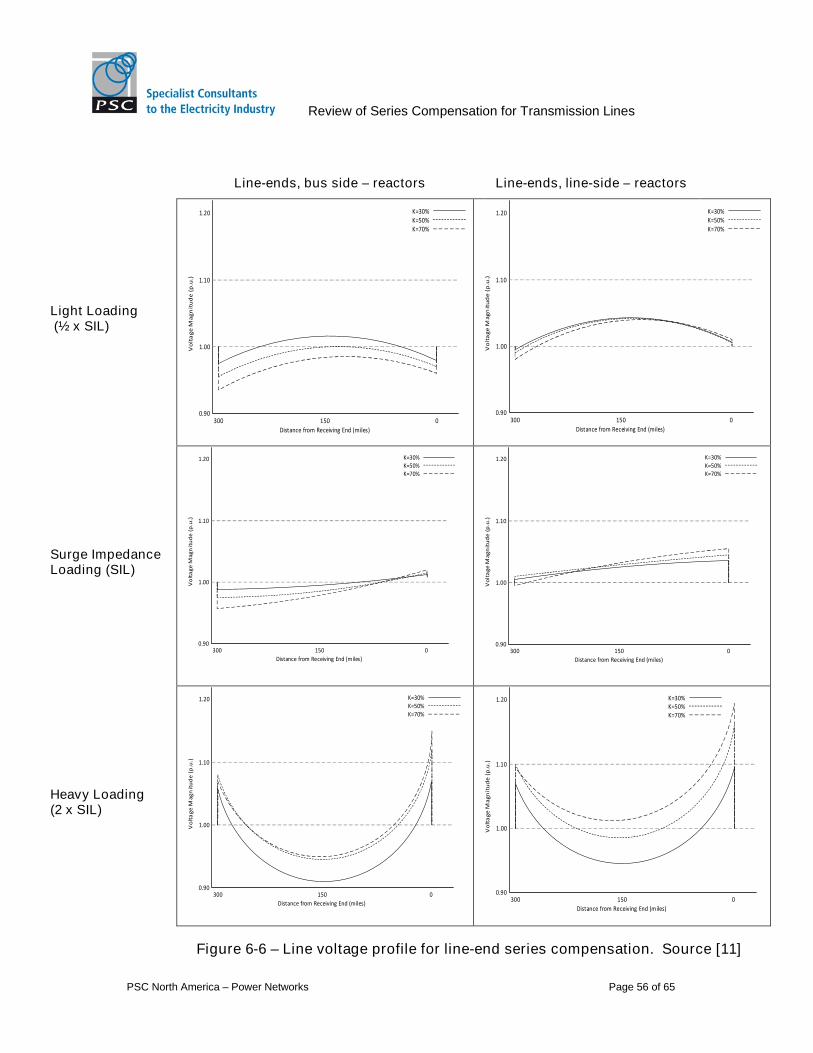
Review of Series Compensation for Transmission Lines
PSC North America – Power Networks Page 56 of 65
Line-ends, bus side – reactors Line-ends, line-side – reactors
Light Loading(½ x SIL)
150 0
1.00Vo
lta
ge
Ma
gn
itu
de
(p.u
.)
Distance from Receiving End (miles)
0.90
1.10
1.20
300
K=30%K=50%K=70%
150 0
1.00Vo
lta
ge
Mag
nit
ud
e(p
.u.)
Distance from Receiving End (miles)
0.90
1.10
1.20
300
K=30%K=50%K=70%
Surge ImpedanceLoading (SIL)
150 0
1.00Vo
lta
ge
Ma
gn
itu
de
(p.u
.)
Distance from Receiving End (miles)
0.90
1.10
1.20
300
K=30%K=50%K=70%
150 0
1.00Vo
lta
ge
Ma
gn
itu
de
(p.u
.)
Distance from Receiving End (miles)
0.90
1.10
1.20
300
K=30%K=50%K=70%
Heavy Loading(2 x SIL)
150 0
1.00Vo
lta
ge
Mag
nit
ud
e(p
.u.)
Distance from Receiving End (miles)
0.90
1.10
1.20
300
K=30%K=50%K=70%
150 0
1.00Vo
lta
ge
Ma
gn
itu
de
(p.u
.)
Distance from Receiving End (miles)
0.90
1.10
1.20
300
K=30%K=50%K=70%
Figure 6-6 – Line voltage profile for line-end series compensation. Source [11]

Review of Series Compensation for Transmission Lines
PSC North America – Power Networks Page 57 of 65
Advantages:
Use of available space, no access issues when in substation
Easier access to banks and equipment for maintenance and operations
No additional site to acquire
Disadvantages:
Lower effectiveness meaning more compensation for the same impact
Increased short circuit-circuit currents require higher bypass equipment ratings
Further expansion:
Totally depends on space availability;
Further compensation can be added at cut in points if flows are greatly increased.
6.3 Modularity of Series Compensation
A series capacitor installation can consist of more than one module and the installationof the modules can be staged according to planning and project requirements. Eachmodule consists of a capacitor bank, MOV and bypass circuit for the three phases sothat each module can be operated independently. [48]
Series capacitor installations are generally installed in single modules to reduce capitalcosts. In some cases, particularly where future uncertainty is high, modularity presentscertain advantages [11]:
Staged development lowers risk of stranded assets if ultimate transmissioncapacity is not required;
The addition of a bus between modules increases flexibility for future connectionsallowing for the future connection of a circuit to a generator, load or substation ina tee-off arrangement;
Individual modules can be switched independently in steps to allow for greaterflexibility to the system operator under varying system loads;
Additional modules could consist of TCSC units allowing for control of dynamicstability issues that could arise in the future; and
Allows for conditions where high levels of compensation and high currents resultin voltage variations across the banks that exceed standard equipmentspecifications.
At a minimum, one platform is required per phase and generally each module will bebuilt on its own platforms. However, in instances where it is virtually certain that theultimate compensation levels will be achieved it may be economically viable to build alarger platform from the outset and add additional modules to the same platform.Provision would need to be made for allowing switching and control equipment to beaccessible at ground level.
The modules can be connected directly or to a common bus. Connecting directly willreduce capital costs but limit flexibility for future expansion and reconfiguration.

Review of Series Compensation for Transmission Lines
PSC North America – Power Networks Page 58 of 65
The principal disadvantage to modularity is the increased capital cost per ohm ofcompensation.
6.4 Future Development of the Series Compensated Lines
The configuration of the initially installed series compensation will impact on the futureextendibility of the network.
The impact of future segmentation is dependent on the location of the series capacitor/son the transmission line, the magnitude of compensation and the specific nature of thenew addition. In general, if future network modifications are committed or likely, then thisshould be included in the initial studies for the series capacitors.
The type of the new addition, i.e. load or generation, and its location in relation to theseries capacitor/s are significant factors when analyzing the impact of said addition.Load may be subjected to over-voltages that significantly exceed the typicalovervoltages impressed on other loads on the system. If generators are added thenshort-circuit, stability and SSR studies will need to be repeated.
The magnitude and configuration of the initial capacitor bank installation may precludefuture segmentation of the transmission line with significant cost to reconfiguration theseries compensation if not considered up front.
6.5 Operations and Maintenance Considerations
Operation of series compensation equipment requires a robust Control and Protection(C&P) system to operate efficiently with the connected transmission line. The C&Psystem provides constant monitoring of the equipment to provide appropriate protectiveactions during external line and internal equipment fault conditions, and deliver real timemonitoring of components. The C&P system’s real time monitoring can give indication ofabnormal operating conditions within the equipment to allow for repairs to be scheduledto appropriately mitigate the risk of a subsequent forced outage of the seriescompensation or possibly the entire line.
Operations and Maintenance (O&M) requirements for series compensation would addminimal impacts to the current utility operations. A majority of the equipment used inseries compensation is most likely already found in the typical high voltage transmissionsystems. Equipment includes capacitor banks, reactors, circuit breakers, switches, andMOV arresters which can easily be introduced into the current utility O&M policies. Usualmaintenance items would include:
Infrared (IR) scans of equipment for hotspots or overloads;
Visual inspections to identify damaged equipment such as leaking capacitors orbroken insulators;
Verification of density monitors in SF6 filled equipment;
Periodic capacitor measurements; and
Ordinary inspections maintenance as required by the manufacturer.
Thyristor Controlled Series Compensation (TCSC) requires power electronics which willhave additional maintenance requirements. These power electronics are the same thathave operated reliably in HVDC converters, SVCs, and medium voltage motor drives for
Review of Series Compensation for Transmission Lines
PSC North America – Power Networks Page 59 of 65
decades. The additional maintenance would be limited to periodic inspection of thepower electronic cooling system and replacement of faulty power electronic moduleswhen they are identified by the C&P system. The TCSC will have redundant powerelectronic modules built in to system to allow for replacement during plannedmaintenance periods.
6.5.1 Operations and Reliability
Real time information such as alarms or equipment status would typically be provided viaRTU or Remote Control Interface to the SCADA/EMS at the local and/or area systemcontrol center(s). The switch from local to remote control would typically require handofffrom the local control unit.
Remote control capabilities can be customized to permit the system operator to performcertain functions from the SCADA/EMS. For example, the system operator could bepermitted to manually by-pass the series capacitor based on network conditions (i.e., toavoid the potential for SSI following certain contingencies). Special C&P interlockingmay be required for remote access security. Remote control functionality should bedetermined and specified as early as possible to avoid modification requirements afterinitial design, installation and testing.
The expected utilization level and required availability of a series compensatedtransmission should be factored into the location and design for the compensationdevice(s). Some basic considerations include:
Single, partly redundant, or completely redundant C&P systems.
Compensation in the middle of the transmission line or alternatively, at one orboth ends. The time for personnel to respond to series capacitor location(s) aswell as the reliability of required communications will be a function of thelocation(s).
Split of the series capacitor blocks onto separate energized platforms, per phase.50% series compensation could be split into two 25% blocks to increase overallavailability and power transfer capability with consideration of scheduled andforced outage rates for each block.
Staffing and availability of qualified maintenance personal to respond to alarmsand device issues on a 24/7 basis in accordance with utility best practices andprocedures.
Specification of digital fault recorders (DFR) and/or sequence of events recorders(SER) to provide tools for more efficient fault tracing and corrective measures.

Review of Series Compensation for Transmission Lines
PSC North America – Power Networks Page 60 of 65
7 Roadmap for Further Analysis
7.1 Preliminary Design Stage Studies
During the preliminary design stage of series compensation projects, various steadystate and transient studies are required to determine technical specifications to provideto vendors. The model used for the series capacitor and the bypass system isdependent on the study conducted.
The design parameters required from the preliminary analysis are
Series capacitor bank rated impedance;
Series capacitor bank rated current, overload current;
Series capacitor bank insulation requirements;
Varistor energy requirements; and
Number of series compensation modules and or intermediate steps.
To determine these variables, the following studies are required.
7.2 Steady state data for analyzing the active and reactive powerflows and voltage profiles in the system
The series capacitor can be modelled simply as a negative reactance connected inseries with the transmission line. Note that when conducting the study either “Newton” or“Modified Gauss-Seidel” solution techniques must be used as the traditional “Gauss-Seidel” solution technique cannot handle series capacitors.
Short circuit data for analyzing the fault currents flowing in the system as well as theseries capacitor for various system configurations during internal and external faults. Thethrough fault current is needed to identify the required ratings for the series capacitor.The model representation of the series capacitor during the short circuit will changedepending on whether the bypass spark gap has triggered or the bypass varistors areconducting a significant amount of current. This depends on how the fault type andlocation affects the voltage across the bypass devices. For faults external to the seriescapacitor several iterations of short circuit calculations may be required to determine thebypass path representation for any given fault location and type, so a range of values forpositive, negative, and zero sequence information may be appropriate for an accuraterepresentation in a short circuit study. An EMT analysis can be used to determine anequivalent impedance for the bypass path, to be used in the PSS/E short circuit analysisbut would only be valid for a particular fault location and system configuration. If only theworst case extremes of fault current magnitude (ignoring fault current phase, which isimportant for relay settings) are required then for external faults:
The highest fault currents (at the point of fault) would be obtained with the bypasscircuit open, so the positive and zero sequence impedance of the seriescapacitor itself is sufficient information for sequence components of the model,and;
The lowest fault currents (at the point of fault) would be obtained with the seriescapacitor bypassed completely. In this case no information is required – theseries capacitor can be modelled as a zero impedance branch.

Review of Series Compensation for Transmission Lines
PSC North America – Power Networks Page 61 of 65
7.3 Transient Stability Analysis
The short circuit representation of the bypass path is be used to represent the faultimpedance. After the fault is cleared the bypass path must continue to be modelled untilit ceases to conduct current. PSS/E v30 (and higher) dynamics application offers aseries capacitor gap model (SCGAP2). This model will bypass the capacitor after adefined time, if the capacitor current (and associated capacitor voltage) exceed adefined value. The capacitor can be reinserted if the current falls below a defined value,or permanently shorted by a bypass switch. Note that the varistor action is not modelledas it is assumed to be sufficiently brief so as to not affect the stability response.
7.4 Harmonics and Frequency Scans
Frequency scan studies will need to be carried out for both sub-synchronous andharmonic frequencies.
For sub-synchronous frequencies, frequency scans should be conducted to determinethe driving-point system impedance as seen from the neutral point of each nearbygenerator. The intent is to identify any sub-synchronous resonance issues.
For harmonics, scans will assess the change in system impedance at either end of theinterconnector and at selected major buses elsewhere in the system, between thepresent conditions and following installation of the series compensation in credibleoperating conditions. This information can then be used to identify whether harmonicresonances are likely to be worsened appreciably by the introduction of seriescompensation.
7.5 Short-term Transient Voltage and Switching Studies
The following fast transient studies are typically carried out using an electromagnetictransient type program such as EMTP-RV or PSCAD/EMTDC:
1) Lightning Strikes in the vicinity of the series capacitor
a) Direct strikes to phase conductors due to shielding failure
b) Back-flash from tower to phase conductor due to high stroke current
c) Shielding failure at the substation
2) Energization and de-energization of compensated line
a) Energization from either end with capacitor inserted/bypassed
b) De-energization from either end with capacitor inserted/bypassed, includingbreaker TRV
3) Bypass and insertion of capacitor under load
4) Fault response for
a) Different fault types
i) 1-phase-ground (with and without single phase auto-reclose)
ii) 2-phase
iii) 2-phase-ground

Review of Series Compensation for Transmission Lines
PSC North America – Power Networks Page 62 of 65
iv) 3-phase
b) Different fault locations
i) Within capacitor
ii) On compensated line
iii) On adjacent lines
c) Transformer or shunt reactor energization on lightly loaded series compensatedline for ferro-resonance effects.
These studies will determine the maximum energy on varistors, maximum transientvoltage and current on capacitors, and TRV on circuit breakers. They also serve to sizeMOV and damping circuit components.
7.6 Small-signal Analysis
The use of series capacitors in a power system typically improves small signal stabilityby reducing the series inductive reactance between regions. In general the impact ofseries capacitors range from increasing the frequency of local/area/regional modes ofoscillation, dampening the oscillations, or a combination of both.
No special mitigation measures are envisaged however an eigenvalue analysis shouldstill be carried out on the pre and post compensated system to determine the specificimpact of the series capacitors. This will identify the impact of the series capacitors oncurrent modes of oscillations, and should consider a range of credible networkconfigurations, generation dispatch profiles (including wind), demand scenarios, andinter-state power transfers. In addition, small signal models are needed for generators(including wind) and HVDC. This may require the re-tuning of any Power SystemStabilizers present on generating units.
Review of Series Compensation for Transmission Lines
PSC North America – Power Networks Page 63 of 65
8 References
[1] ABB. (2010). “Series Compensation – Boosting transmission capacity”. A02-0135E, 2010-12
[2] ABB. (2010). “TCSC – Thyristor Controlled Series Compensation – Keeping gridstogether”. A02-0158E, 2010-03
[3] ABB. (2012). “Series Compensated Line Protection”. ABB Webinar.http://www.youtube.com/watch?v=rKWnMyTYUDM
[4] ABB Group. (2010). “ERCOT CREZ Reactive Study, RPG SSI Discussion 2010”.ABB Group Presentation
[5] Adams. (2011). “Sub-Synchronous Problems and Prevention in ERCOT”. ERCOTRPG Presentation
[6] Adams. (2012). “ERCOT Experience Screening for Sub-Synchronous ControlInteraction in the Vicinity of Series Capacitor Banks”. IEEE PES General Meeting,San Diego, CA. Presentation
[7] Adams. (2012). “Planning Guide concepts for dealing with SubsynchronousResonance in ERCOT and other issues”. ERCOT
[8] Agrawal and Farmer. (1979). “Use of Frequency Scanning Techniques forSubsynchronous Resonance Analysis”. Vol.PAS-98, No.2: IEEE Transactions onPower Apparatus and Systems
[9] Alomari and Rodanski. (2007). “STATCOM for Controlling Bifurcations of SSR asApplied to Multimachine Power System”. University of Technology, Sydney,Australia
[10] Altuve, Mooney and Alexander. (2008). “Advances in Series-CompensatedTransmission Lines”. TP6340-01, Schweitzer Engineering Laboratories, Inc.
[11] Anderson and Farmer. (1996). “Series Compensation of Power Systems”.Encinitas, CA: PBLSH, Inc.
[12] Badrzadeh, Sahni, Muthumuni, Zhou and Gole. (2012). “Sub-synchronousInteraction in Wind Power Plants – Part I: Study Tools and Techniques”. 978-1-4673-2729-9: IEEE
[13] Buntales. “SSR Protection”. Chapter 29[14] Chano. (2008). “Transmission Line Protection – Doing it Right”. Cover Story-
Winter 2008, pacworld[15] Donghui, Xiaorong, Shiya and Shuqing. (2004). “Optimal design of SEDC for
damping multi-mode SSR based on GASA”. Department of Electrical Engineering,Tsinghua University, Beijing, China
[16] Donohoo. “Planners Perspective on Series Compensated Transmission Lines”ONCOR Presentation
[17] ERCOT. “Resource Interconnection Handbook”. Version 1.2: ERCOT[18] Erwin, Pineda, Anderson, Tziouvaras and Turner. (2013).”PG&E 500kV Series-
Compensated Transmission Line Relay Replacement: Design Requirements andRTDS Testing”. PG&E and SEL, Inc. Presentation.
[19] Farmer, Agrawal and Ramey. (2006). “Power System Dynamic Interaction withTurbine Generators”, Taylor and Francis Group, LLC.http://www.beknowledge.com/wp-content/uploads/2010/09/327.pdf
[20] Gross. (2010). “Sub-Synchronous Grid Conditions: New Event, New Problem, andNew Solutions”. 37th Annual Western Protective Relay Conference, Spokane, WA

Review of Series Compensation for Transmission Lines
PSC North America – Power Networks Page 64 of 65
[21] Gusmán, Mooney, Benmouyal and Fischer. (2001). “Transmission Line ProtectionSystem for Increasing Power System Requirements”. 20020401: SchweitzerEngineering Laboratories, Inc.
[21b] Hosseini and Tousi. (2012). “Mitigating of Sub-synchronous Resonance in a SeriesCompensated Hybrid System with Steam and Wind Turbine Using FACTSControllers”. Majlesi Journal of Electrical Engineering. Vol. 6. No. 3
[22] IEEE. (2007). “IEEE Guide for Protective Relay Application to Transmission-LineSeries Capacitor Banks”, IEEE Power Engineer Society – Power Systems RelayingCommittee, Std C37:116-2007
[22b] IEEE. (1992). “Reader’s Guide to Subsynchronous Resonance”. Transactions onPower Systems, Vol. 7, No. 1, 0885-8950/92: IEEE
[23] Irwin. (2010). “Sub-Synchronous Interactions with Wind Turbines”, CREZPresentation 2010
[24] Jianbo, Gesong, Jiming, Baiquing and Weizhou. (2005). “Chengxian 220kVThyristor Controlled Series Compensation: Parameters Design, Control &Overvoltage Protection”, IEEE/PES Transmission and Distribution Conference,Asia and Pacific, Dalian China, 0-7803-9114-4: IEEE
[25] Karawita. (2012). “Analysis of Sub-synchronous Frequency Interactions in PowerSystems Using TGSSR”. IEEE PES Winnipeg Section Luncheon Meeting. TGSPresentation.
[26] Kasztenny. (2001). “Distance Protection of Series-compensated Lines: Problemsand Solutions”. GER-3998: GE Power Management
[27] Larsen. (2012). “Wind Power On Series-Compensated Lines”. IEEE PES GeneralMeeting, San Diego, CA. Presentation by GE Energy Consulting
[28] Leonidaki, Hatziargyiou, Papadias and Geoargantzis. (1998). “Investigation ofPower System Harmonics and SSR Phenomena related to Thyristor ControlledSeries Capacitors”. 8th International Conference on Harmonic and Quality ofPower (ICHQP), Athens Greece, 0-7803-5105-3: IEEE
[29] Nekoubin. (2011). “Simulation of Series Compensated Transmission LinesProtected with MOV”. World Academy of Science, Engineering and Technology,Vol: 58
[30] NERC. (2011). “Lessons Learned – SSI between Series CompensatedTransmission Lines and Generation”. LL_45_SSSI: NERC
[31] Ma, Brogan, Jensen and Nelson. (2012) “Sub-Synchronous Control InteractionStudies between Full-Converter Wind Turbines and Series-Compensated ACTransmission Lines”. IEEE PES General Meeting, San Diego, CA. Presentation bySiemens Wind Turbines
[32] Padiyar and Prabhu. “Investigation of SSR characteristics of UPFC”. Department ofElectrical Engineering, Indian Institute of Science, Bangalore 560012, India
[33] Plumptree, Nagpal, Chen and Thompson. (2009). “Protection of EHV TransmisisonLines With Series Compensation: BC Hydro’s Lessons Learned”. 978-1-4244-4183: IEEE
[34] Rajaraman and Dobson. (1996). “Damping estimates of subsynchronous andpower swing oscillations in power systems with thyristor switching devices”. Vol.11, No. 3: IEEE Transactions on Power Systems
[35] Sahni, Badrzadeh, Muthumuni, Cheng, Yin, Huang and Zhou. (2012). “Sub-synchronous Interaction in Wind Power Plants – Part II: An ERCOT Case Study”.978-1-4673-2729-9: IEEE
Review of Series Compensation for Transmission Lines
PSC North America – Power Networks Page 65 of 65
[36] Saylors. (2013). “Understanding and Assessing Subsynchronous Resonance”.NAW1308: North American Windpower
[37] Shahgholian. (2013). “Review of PSS: Application, Modeling, Analysis and ControlStrategy”. Issue 16, Vol. 3, Num. 3, Pages 41-52: IJTPE Journal
[38] Subhash, Tripathy, Padiyar, Nayyar, Kumar, Thakkar and Arya. (2005). “SSR studyfor the TCSC application on the Kanpur-Ballabgarh 400 kV line in India”.International Conference on Power System Transients. Paper No. IPST05-043
[39] Sun, Ban, Yang and Wang. (2013). “Application of STATCOM for DampingSubsynchronous Resonance in a Multi-machine System”. Engineering, 2013, 5,180-184: Scientific Research
[40] Suriyaarachchi, Annakkage, Karawite, Kell, Mendis and Chopra. (2012).“Application of an SVC to Damp Sub-synchronous Interaction Between WindFarms and Series Compensated Transmission Lines”. IEEE PES Presentation,San Diego, CA
[41] Varma, Auddy and Semsedini. (2008). “Mitigation of Subsynchronous Resonancein Series-Compensated Wind Farm Using FACTS Controllers”. Vol. 23, No.3: IEEETransactions on Power Delivery
[42] Vuorenpää, Rauhala, Järventausta and Acha. (2013). “On Assessing the Risk ofSSR Related Torque Amplification in Series Compensated Networks”. InternationalConference on Power Systems Transients (IPST2013), Vancouver, Canada
[43] Wilkinson. “Series Compensated Line Protection Issues”. GER-3972: GE PowerManagement
[44] Wu, Zhu and Hu. (2012) “Supplementary Controller Design for SSR Damping in aSeries-compensated DFIG-Based Wind Farm”. ISSN 1996-1073: Energies
[45] Xia, Johnson, Fischer, and Xia. (2013). “A Comparison of Different SignalSelection Options and Signal Processing Techniques for SubsynchronousResonance Detection”. International Conference on Power Systems Transients(IPST2013) in Vancouver, Canada
[46] Zellagui and Chaghi. (2011). “Impact of Series Compensation (SC) on the MHODistance Relay in Algerian 220 kV Transmission Line”. Canadian Journal onElectronic and Electronics Engineering, Vol. 2, No. 6
[47] Zhang and Zheng. (2007). “Effect of Exciter and PSS on SSR Damping”. 1-4244-1298-6: IEEE
[48] IEC 60143 ‘Series Capacitors for Power Systems’, Parts 1, 2, and 4