Embed Size (px)
Citation preview
Review of Options for Offshore Foundation Substructures
Prepared by the Center for Wind Energy at James Madison University
August 2012
An offshore wind turbine is massive in size – from the root of their foundation to the top of the nacelle,
wind turbines can reach a height of 250 meters (820 feet).1 Upcoming offshore wind turbines are rated
at 5MW and larger turbines of up to 10MW are being developed. As wind turbines get larger, the
importance of developing cost-effective foundations that can safely support these turbines increases.
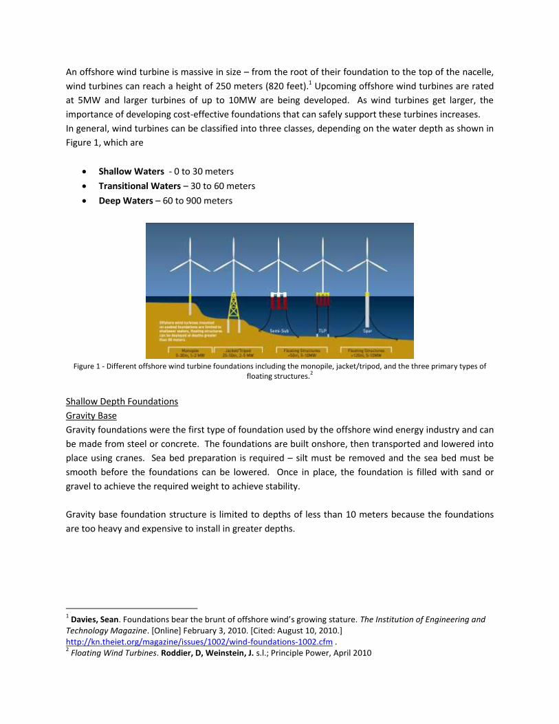
In general, wind turbines can be classified into three classes, depending on the water depth as shown in
Figure 1, which are
Shallow Waters - 0 to 30 meters
Transitional Waters – 30 to 60 meters
Deep Waters – 60 to 900 meters
Figure 1 - Different offshore wind turbine foundations including the monopile, jacket/tripod, and the three primary types of
floating structures.2
Shallow Depth Foundations
Gravity Base
Gravity foundations were the first type of foundation used by the offshore wind energy industry and can
be made from steel or concrete. The foundations are built onshore, then transported and lowered into
place using cranes. Sea bed preparation is required – silt must be removed and the sea bed must be
smooth before the foundations can be lowered. Once in place, the foundation is filled with sand or
gravel to achieve the required weight to achieve stability.
Gravity base foundation structure is limited to depths of less than 10 meters because the foundations
are too heavy and expensive to install in greater depths.
1 Davies, Sean. Foundations bear the brunt of offshore wind’s growing stature. The Institution of Engineering and
Technology Magazine. [Online] February 3, 2010. [Cited: August 10, 2010.] http://kn.theiet.org/magazine/issues/1002/wind-foundations-1002.cfm . 2 Floating Wind Turbines. Roddier, D, Weinstein, J. s.l.; Principle Power, April 2010
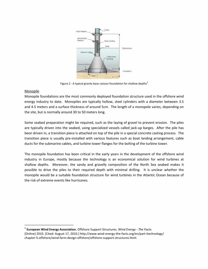
Figure 2 - A typical gravity base caisson foundation for shallow depths
3
Monopile
Monopile foundations are the most commonly deployed foundation structure used in the offshore wind
energy industry to date. Monopiles are typically hollow, steel cylinders with a diameter between 3.5
and 4.5 meters and a surface thickness of around 5cm. The length of a monopole varies, depending on
the site, but is normally around 30 to 50 meters long.
Some seabed preparation might be required, such as the laying of gravel to prevent erosion. The piles
are typically driven into the seabed, using specialized vessels called jack-up barges. After the pile has
been driven in, a transition piece is attached on top of the pile in a special concrete casting process. The
transition piece is usually pre-installed with various features such as boat landing arrangement, cable
ducts for the submarine cables, and turbine tower flanges for the bolting of the turbine tower.
The monopile foundation has been critical in the early years in the development of the offshore wind
industry in Europe, mostly because the technology is an economical solution for wind turbines at
shallow depths. Moreover, the sandy and gravelly composition of the North Sea seabed makes it
possible to drive the piles to their required depth with minimal drilling. It is unclear whether the
monopile would be a suitable foundation structure for wind turbines in the Atlantic Ocean because of
the risk of extreme events like hurricanes.
3 European Wind Energy Association. Offshore Support Structures. Wind Energy - The Facts.
[Online] 2010. [Cited: August 17, 2010.] http://www.wind-energy-the-facts.org/en/part-itechnology/ chapter-5-offshore/wind-farm-design-offshore/offshore-support-structures.html.
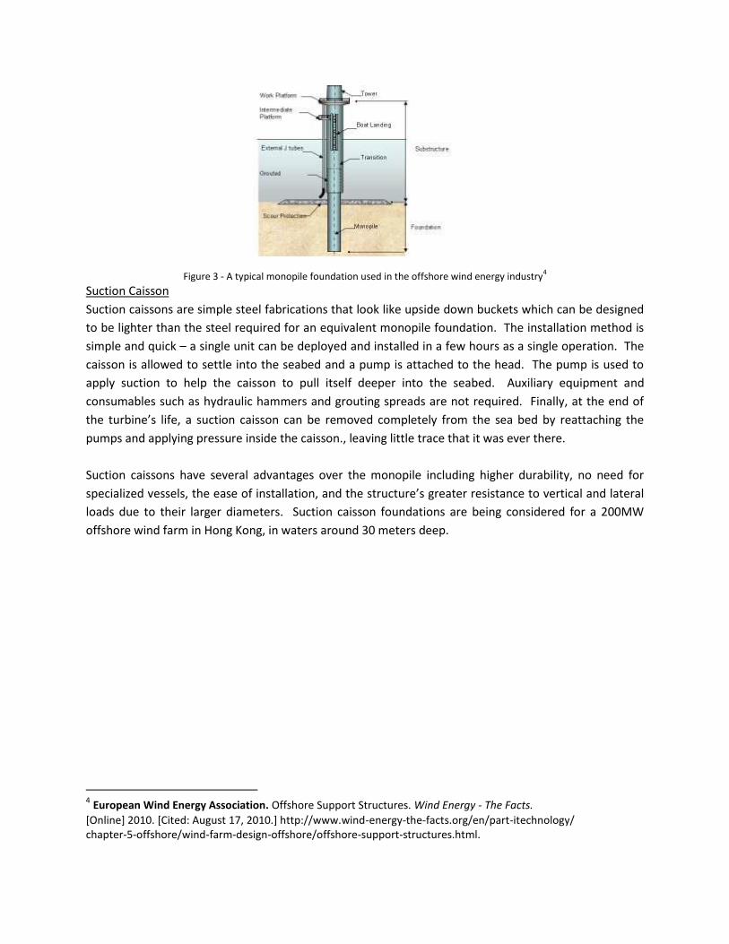
Figure 3 - A typical monopile foundation used in the offshore wind energy industry
4
Suction Caisson
Suction caissons are simple steel fabrications that look like upside down buckets which can be designed
to be lighter than the steel required for an equivalent monopile foundation. The installation method is
simple and quick – a single unit can be deployed and installed in a few hours as a single operation. The
caisson is allowed to settle into the seabed and a pump is attached to the head. The pump is used to
apply suction to help the caisson to pull itself deeper into the seabed. Auxiliary equipment and
consumables such as hydraulic hammers and grouting spreads are not required. Finally, at the end of
the turbine’s life, a suction caisson can be removed completely from the sea bed by reattaching the
pumps and applying pressure inside the caisson., leaving little trace that it was ever there.
Suction caissons have several advantages over the monopile including higher durability, no need for
specialized vessels, the ease of installation, and the structure’s greater resistance to vertical and lateral
loads due to their larger diameters. Suction caisson foundations are being considered for a 200MW
offshore wind farm in Hong Kong, in waters around 30 meters deep.
4 European Wind Energy Association. Offshore Support Structures. Wind Energy - The Facts.
[Online] 2010. [Cited: August 17, 2010.] http://www.wind-energy-the-facts.org/en/part-itechnology/ chapter-5-offshore/wind-farm-design-offshore/offshore-support-structures.html.
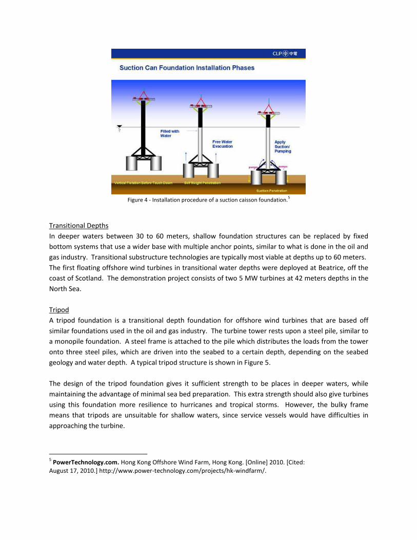
Figure 4 - Installation procedure of a suction caisson foundation.
5
Transitional Depths
In deeper waters between 30 to 60 meters, shallow foundation structures can be replaced by fixed
bottom systems that use a wider base with multiple anchor points, similar to what is done in the oil and
gas industry. Transitional substructure technologies are typically most viable at depths up to 60 meters.
The first floating offshore wind turbines in transitional water depths were deployed at Beatrice, off the
coast of Scotland. The demonstration project consists of two 5 MW turbines at 42 meters depths in the
North Sea.
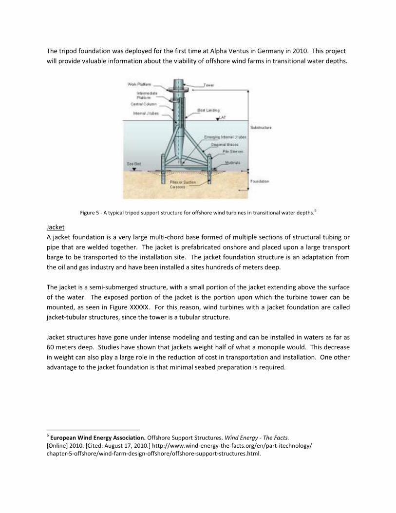
Tripod
A tripod foundation is a transitional depth foundation for offshore wind turbines that are based off
similar foundations used in the oil and gas industry. The turbine tower rests upon a steel pile, similar to
a monopile foundation. A steel frame is attached to the pile which distributes the loads from the tower
onto three steel piles, which are driven into the seabed to a certain depth, depending on the seabed
geology and water depth. A typical tripod structure is shown in Figure 5.
The design of the tripod foundation gives it sufficient strength to be places in deeper waters, while
maintaining the advantage of minimal sea bed preparation. This extra strength should also give turbines
using this foundation more resilience to hurricanes and tropical storms. However, the bulky frame
means that tripods are unsuitable for shallow waters, since service vessels would have difficulties in
approaching the turbine.
5 PowerTechnology.com. Hong Kong Offshore Wind Farm, Hong Kong. [Online] 2010. [Cited:
August 17, 2010.] http://www.power-technology.com/projects/hk-windfarm/.
The tripod foundation was deployed for the first time at Alpha Ventus in Germany in 2010. This project
will provide valuable information about the viability of offshore wind farms in transitional water depths.
Figure 5 - A typical tripod support structure for offshore wind turbines in transitional water depths.
6
Jacket
A jacket foundation is a very large multi-chord base formed of multiple sections of structural tubing or
pipe that are welded together. The jacket is prefabricated onshore and placed upon a large transport
barge to be transported to the installation site. The jacket foundation structure is an adaptation from
the oil and gas industry and have been installed a sites hundreds of meters deep.
The jacket is a semi-submerged structure, with a small portion of the jacket extending above the surface
of the water. The exposed portion of the jacket is the portion upon which the turbine tower can be
mounted, as seen in Figure XXXXX. For this reason, wind turbines with a jacket foundation are called
jacket-tubular structures, since the tower is a tubular structure.
Jacket structures have gone under intense modeling and testing and can be installed in waters as far as
60 meters deep. Studies have shown that jackets weight half of what a monopile would. This decrease
in weight can also play a large role in the reduction of cost in transportation and installation. One other
advantage to the jacket foundation is that minimal seabed preparation is required.
6 European Wind Energy Association. Offshore Support Structures. Wind Energy - The Facts.
[Online] 2010. [Cited: August 17, 2010.] http://www.wind-energy-the-facts.org/en/part-itechnology/ chapter-5-offshore/wind-farm-design-offshore/offshore-support-structures.html.
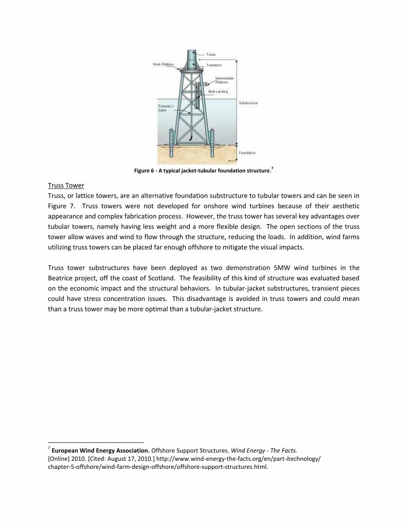
Figure 6 - A typical jacket-tubular foundation structure.
7
Truss Tower
Truss, or lattice towers, are an alternative foundation substructure to tubular towers and can be seen in
Figure 7. Truss towers were not developed for onshore wind turbines because of their aesthetic
appearance and complex fabrication process. However, the truss tower has several key advantages over
tubular towers, namely having less weight and a more flexible design. The open sections of the truss
tower allow waves and wind to flow through the structure, reducing the loads. In addition, wind farms
utilizing truss towers can be placed far enough offshore to mitigate the visual impacts.
Truss tower substructures have been deployed as two demonstration 5MW wind turbines in the
Beatrice project, off the coast of Scotland. The feasibility of this kind of structure was evaluated based
on the economic impact and the structural behaviors. In tubular-jacket substructures, transient pieces
could have stress concentration issues. This disadvantage is avoided in truss towers and could mean
than a truss tower may be more optimal than a tubular-jacket structure.
7 European Wind Energy Association. Offshore Support Structures. Wind Energy - The Facts.
[Online] 2010. [Cited: August 17, 2010.] http://www.wind-energy-the-facts.org/en/part-itechnology/ chapter-5-offshore/wind-farm-design-offshore/offshore-support-structures.html.
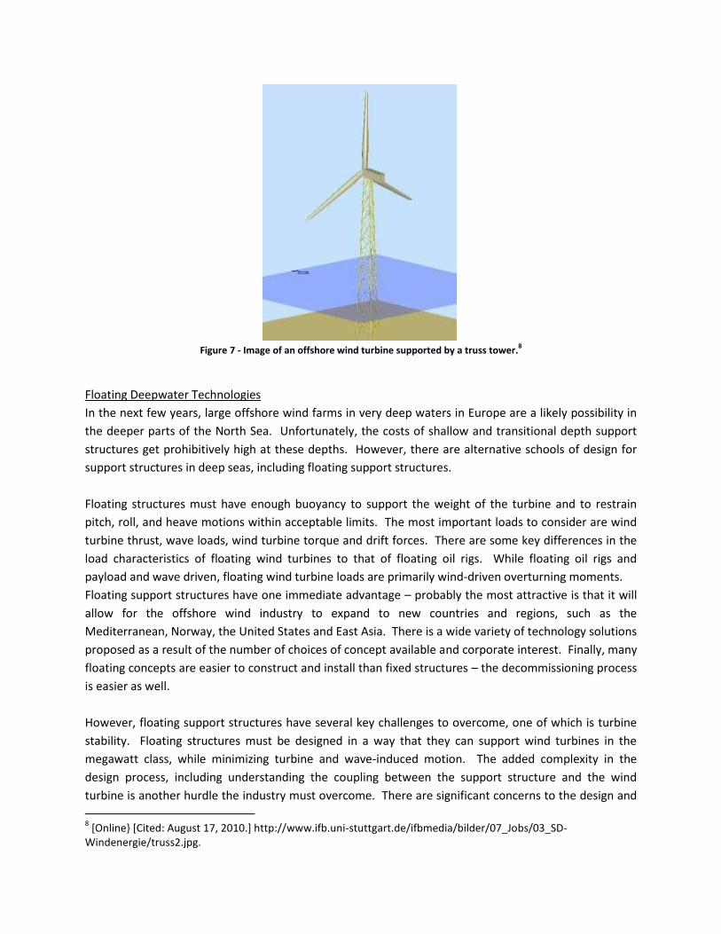
Figure 7 - Image of an offshore wind turbine supported by a truss tower.
8
Floating Deepwater Technologies
In the next few years, large offshore wind farms in very deep waters in Europe are a likely possibility in
the deeper parts of the North Sea. Unfortunately, the costs of shallow and transitional depth support
structures get prohibitively high at these depths. However, there are alternative schools of design for
support structures in deep seas, including floating support structures.
Floating structures must have enough buoyancy to support the weight of the turbine and to restrain
pitch, roll, and heave motions within acceptable limits. The most important loads to consider are wind
turbine thrust, wave loads, wind turbine torque and drift forces. There are some key differences in the
load characteristics of floating wind turbines to that of floating oil rigs. While floating oil rigs and
payload and wave driven, floating wind turbine loads are primarily wind-driven overturning moments.
Floating support structures have one immediate advantage – probably the most attractive is that it will
allow for the offshore wind industry to expand to new countries and regions, such as the
Mediterranean, Norway, the United States and East Asia. There is a wide variety of technology solutions
proposed as a result of the number of choices of concept available and corporate interest. Finally, many
floating concepts are easier to construct and install than fixed structures – the decommissioning process
is easier as well.
However, floating support structures have several key challenges to overcome, one of which is turbine
stability. Floating structures must be designed in a way that they can support wind turbines in the
megawatt class, while minimizing turbine and wave-induced motion. The added complexity in the
design process, including understanding the coupling between the support structure and the wind
turbine is another hurdle the industry must overcome. There are significant concerns to the design and
8 [Online} [Cited: August 17, 2010.] http://www.ifb.uni-stuttgart.de/ifbmedia/bilder/07_Jobs/03_SD-
Windenergie/truss2.jpg.
costs of the electrical infrastructure. Finally, there is a lack of experience in deep water offshore wind
farms and care must be taken during construction, installation and O&M procedures.
While no full-scale floating systems have yet been deployed, a number of companies have developed
full-scale prototypes. A number of other companies are still in the concept development stage. Floating
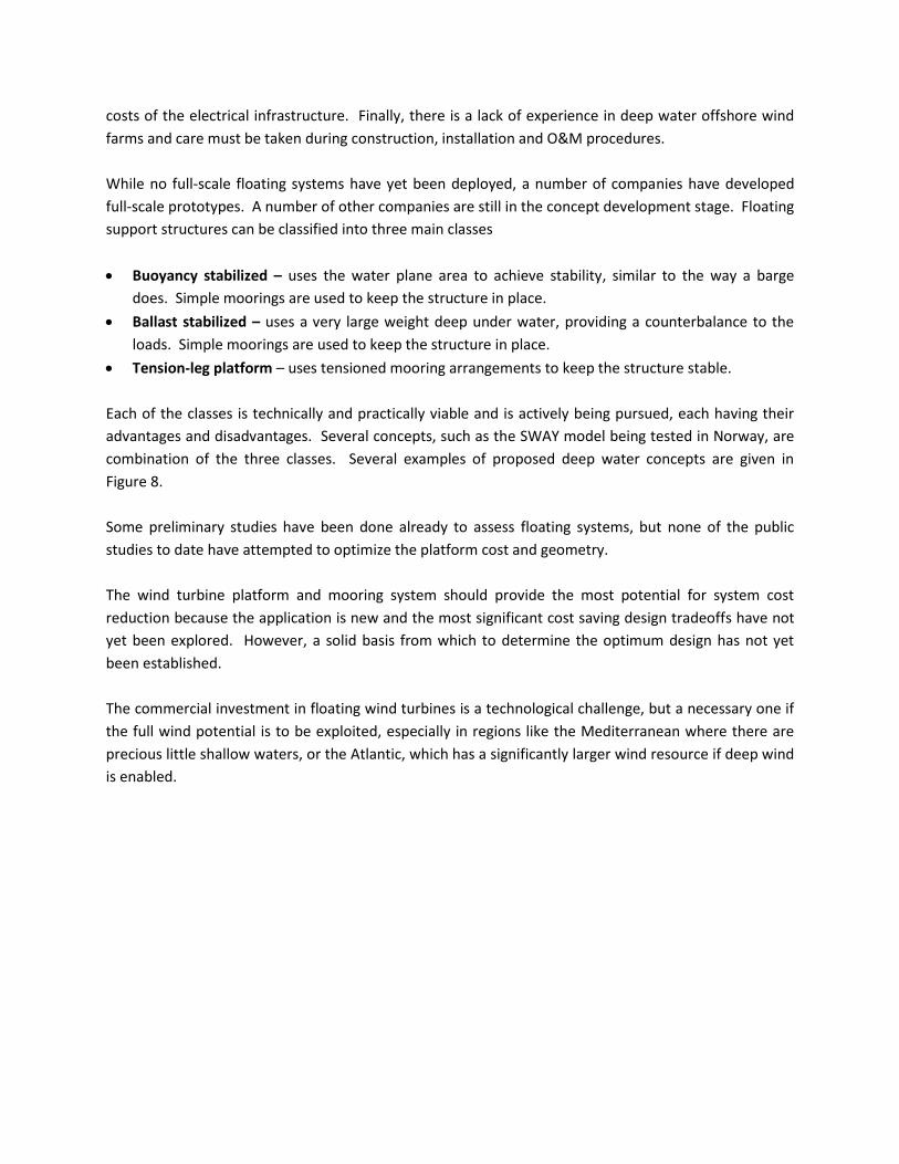
support structures can be classified into three main classes
Buoyancy stabilized – uses the water plane area to achieve stability, similar to the way a barge
does. Simple moorings are used to keep the structure in place.
Ballast stabilized – uses a very large weight deep under water, providing a counterbalance to the
loads. Simple moorings are used to keep the structure in place.
Tension-leg platform – uses tensioned mooring arrangements to keep the structure stable.
Each of the classes is technically and practically viable and is actively being pursued, each having their
advantages and disadvantages. Several concepts, such as the SWAY model being tested in Norway, are
combination of the three classes. Several examples of proposed deep water concepts are given in
Figure 8.
Some preliminary studies have been done already to assess floating systems, but none of the public
studies to date have attempted to optimize the platform cost and geometry.
The wind turbine platform and mooring system should provide the most potential for system cost
reduction because the application is new and the most significant cost saving design tradeoffs have not
yet been explored. However, a solid basis from which to determine the optimum design has not yet
been established.
The commercial investment in floating wind turbines is a technological challenge, but a necessary one if
the full wind potential is to be exploited, especially in regions like the Mediterranean where there are
precious little shallow waters, or the Atlantic, which has a significantly larger wind resource if deep wind
is enabled.
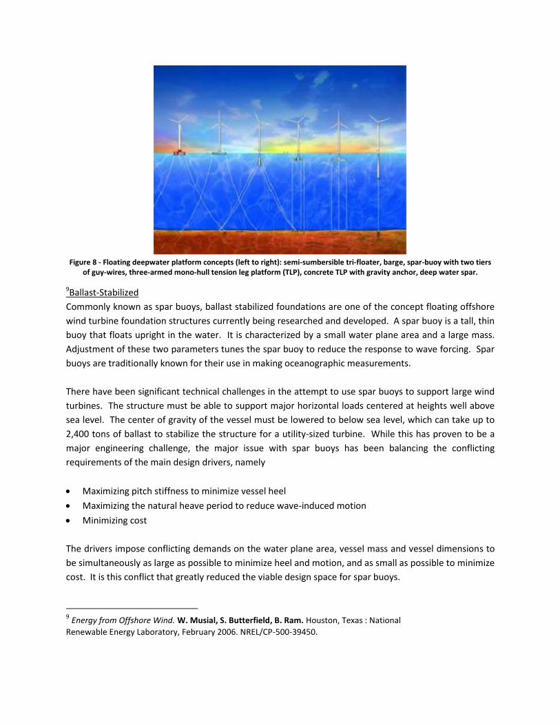
Figure 8 - Floating deepwater platform concepts (left to right): semi-sumbersible tri-floater, barge, spar-buoy with two tiers
of guy-wires, three-armed mono-hull tension leg platform (TLP), concrete TLP with gravity anchor, deep water spar.
9Ballast-Stabilized
Commonly known as spar buoys, ballast stabilized foundations are one of the concept floating offshore
wind turbine foundation structures currently being researched and developed. A spar buoy is a tall, thin
buoy that floats upright in the water. It is characterized by a small water plane area and a large mass.
Adjustment of these two parameters tunes the spar buoy to reduce the response to wave forcing. Spar
buoys are traditionally known for their use in making oceanographic measurements.
There have been significant technical challenges in the attempt to use spar buoys to support large wind
turbines. The structure must be able to support major horizontal loads centered at heights well above
sea level. The center of gravity of the vessel must be lowered to below sea level, which can take up to
2,400 tons of ballast to stabilize the structure for a utility-sized turbine. While this has proven to be a
major engineering challenge, the major issue with spar buoys has been balancing the conflicting
requirements of the main design drivers, namely
Maximizing pitch stiffness to minimize vessel heel
Maximizing the natural heave period to reduce wave-induced motion
Minimizing cost
The drivers impose conflicting demands on the water plane area, vessel mass and vessel dimensions to
be simultaneously as large as possible to minimize heel and motion, and as small as possible to minimize
cost. It is this conflict that greatly reduced the viable design space for spar buoys.
9 Energy from Offshore Wind. W. Musial, S. Butterfield, B. Ram. Houston, Texas : National
Renewable Energy Laboratory, February 2006. NREL/CP-500-39450.
Despite these challenges, a ballast stabilized concept has been developed by the company StatoilHydro.
The concept is currently being testing in the Hywind pilot project over a two-year period. The turbine is
shown in Figure XXXX and is rated at 2.3MW and is designed to operate in water depths between 120-
700 meters. This project will provide valuable information as to how the wind and waves affect the
structure, which will help in the improvement of the design, in particular reducing the cost.
Tension Leg Platforms
Tension leg platforms (TLPs) are also called mooring-line stabilized foundations and are similar to spar
buoys. The mooring-line stabilized turbines are fixed in place with tension leg platforms and suction
gale anchors. These turbines are lighter than ballast stabilized wind turbines which allows for more
motion of the tower. If the motions of the tower are not controlled they can lead to catastrophic
impacts. Currently the mooring line stabilized foundation requires extremely expensive and heavy
foundations in order to prevent motion.
The major challenges in developing a successful design are
Installing the structure safely, reliably and cost effectively while maintaining stability throughout the
entire process, which includes towing, preparation, tensioning of the cable and during submersion
of the structure.
Developing anchoring for ground conditions at the site. Gravity anchors, piled anchors and suction
anchors have all been considered but none are easy or cheap to design or handle.
Despite the challenges, TLPs are considered to have the most potential for success over the other two
classes from both a technical and economic point of view. The TLP concept experiences relatively little
tilting motions. Results published and financed by the Research Fund for the Italian Electrical System in
2007 indicate that TLP systems could be less expensive compared to the other floating concepts.
A preliminary design was developed and evaluated from a technical and economic feasibility standpoint
with reference to a large offshore wind farm with 24 turbines rated at 6MW each. The turbines were
arranged in four rows of six turbines each, placed around 20km offshore in waters 200 meters deep. A
general evaluation of the possible unit cost of the 144MW wind farm was calculated, and an offshore
production cost of around 150€/MWh ($208/MWh) was calculated. Typical onshore wind farms have
production costs of around 120€/MWh ($166/MWh). However, this general calculation is just an
estimate, since annual operation and maintenance costs and annual energy production of offshore wind
farms are still uncertain.
Buoyancy Stabilized
Buoyancy stabilized foundations or hydrostatic turbines are one of the lesser known foundations still
being researched. It has also been called the floating jacket concept. The foundation uses a stabilized
barge on the surface of the ocean in order to support the wind turbines. The barge is stabilized with
catenary mooring lines attached to anchors on the sea bed.
This type of foundation has not found wide practical use yet due to its susceptibility to large waves and
large motions due to waves. The major challenges in developing a successful design are minimizing
wave loads, motion response and structural loads of the floater. The design of catenary moorings
suitable for shallow waters is another engineering challenge for buoyancy stabilized systems.
Foundations have been designed, derived from the oil and natural gas industry, but the gyroscopic
motion of the turbine made this difficult.