Embed Size (px)
Citation preview
TECHNICAL NOTE:
Review of -
Europa Oil and Gas (2017) Holmwood Wellsite -Site Condition Report - Exploratory Operations(document no. EOG-EPRA-HW-SCR-006)
and
Europa Oil and Gas (2017) Holmwood Wellsite - Environmental Risk Assessment – Exploratory Operations(document no. EOG-EPRA-HW-ERA-007)
Environmental Geology & Geotechnical Consultants Ltd22A Beswick StreetAncoatsManchesterM4 7HR
www.eggconsult.co.uk
Tapajós Limited31 Nevill RoadHoveBN3 7BP
www.tapajos.co.uk
EOGSCR/Review/270318/FINAL 1

TECHNICAL NOTE:
Review of -
Europa Oil and Gas (2017) Holmwood Wellsite - Site ConditionReport - Exploratory Operations (document no. EOG-EPRA-
HW-SCR-006)
and
Europa Oil and Gas (2017) Holmwood Wellsite - Environmental Risk Assessment – Exploratory Operations
(document no. EOG-EPRA-HW-ERA-007)
Prepared for:
38 Degrees Ltd40 Bowling Green Lane
Clerkenwell London EC1R 0NE Prepared by:
Aidan Foley and Hanna Landquist EGG Consultants Ltd 22A Beswick Street Ancoats Manchester M4 7HR
Trevor Muten Tapajós Limited 31 Nevill Road Hove BN3 7BP
Document reference;
EOGSCR/Review/270318/FINAL
EOGSCR/Review/270318/FINAL 2
Disclaimer
This Technical Note was produced by Environmental Geology & Geotechnical Consultants Limited and
Tapajós Limited for 38 Degrees Ltd for the specific purpose of a review of Europa Oil and Gas (2017)
‘Holmwood Wellsite Site Condition Report - Exploratory Operations (document no. EOG-EPRA-HW-
SCR-006) and associated supporting information, and Europa Oil and Gas (2017) Holmwood Wellsite -
Environmental Risk Assessment – Exploratory Operations (document no. EOG-EPRA-HW-ERA-007).
This Technical Note may not be used by any person other than 38 Degrees Ltd without their express
permission. In any event, Environmental Geology & Geotechnical Consultants Limited and Tapajós
Limited accept no liability for any costs, liabilities or losses arising from the use of or reliance upon the
contents of this report at all.
Assumptions and Exclusions
Provision of Third Party data.
Environmental Geology & Geotechnical Consultants Ltd and Tapajós Ltd assume that all third party data
are accurate, and assume no responsibility for inaccuracies in information provided by any third party.
General
Any conclusions and recommendations made in this report are limited to those which can be made
based on the findings of the material and information supplied by third parties. Deliverables are supplied
on the basis of the scope of works presented and are not intended for applications outside of this scope.
Site information obtained subsequently to that utilised in this Technical Note, as well as any alterations
in industry standards and/or legislation, may necessitate reinterpretation of data provided under the
scope of works of the deliverable.
Environmental Geology & Geotechnical Consultants Ltd and Tapajós Ltd reserve the right to alter
conclusions and recommendations in the light of additional data arising at some future time.
EOGSCR/Review/270318/FINAL 3

DOCUMENT CONTROL
Document title:
Review of Europa Oil and Gas (2017) Holmwood Wellsite - Site Condition Report - Exploratory Operations (documentno. EOG-EPRA-HW-SCR-006) and Europa Oil and Gas (2017) Holmwood Wellsite - Environmental Risk Assessment –Exploratory Operations (document no. EOG-EPRA-HW-ERA-007).
Document Reference:
EOGSCR/Review/270318/FINAL
Document authored by:
Aidan Foley PhD MSc BA FGS and Hanna Landquist PhD MSc BSc
18th March 2018
Document checked by:
Trevor Muten BSc MSc MPhil FGS CGeol CSci CEnv MCIWEM C.Wem EurGeol
19th March 2018
Document revisions by:
Aidan Foley PhD MSc BA FGS
23rd March 2018
Document authorised by:
Aidan Foley PhD MSc BA FGS
Trevor Muten BSc MSc MPhil FGS CGeol CSci CEnv MCIWEM C.Wem EurGeol
27th March 2018
Signed:
(Aidan Foley, Director, Environmental Geology and Geotechnical Consultants Ltd).
(Hanna Landquist, Engineering Geologist and Risk Assessor, Environmental Geology and Geotechnical ConsultantsLtd)
(Trevor Muten, Director, Tapajós Limited).
Dated:
27th March 2018
EOGSCR/Review/270318/FINAL 4
EXECUTIVE SUMMARY
This Technical Note presents a review of documents submitted by Europa Oil and Gas Ltd in support of an
application to undertake onshore oil and gas exploratory operations at ‘Holmwood Wellsite, Bury Hill Wood,
Coldharbour Lane, Surrey, RH5 6HN’. The Environmental Permit Application number is
EPR/YP3735YK/A001.
The primary document reviewed was the ‘Site Condition Report’ (SCR, document no. EOG-EPRA-HW-SCR-
006). The SCR contains a number of appendices of which, in particular, the ‘Hydrogeological risk
assessment and conceptual model’ (Appendix 3), the ‘Groundwater monitoring strategy’ (Appendix 2), and
the ‘WR11 Application’ (Appendix 4) are reviewed in detail in this Technical Note. The separate application
document ‘Holmwood Wellsite Environmental Risk Assessment’ (document no. EOG-EPRA-HW-ERA-007) is
also reviewed.
Many significant errors, inconsistencies and omissions have been identified throughout the documents
reviewed. These are detailed throughout this Technical Note and the major criticisms are outlined in this
summary.
However, due to time constraints, it has not been possible to robustly review additional documents, notably
the site Waste Management Plan (document no. EOG-EPRA-HW-WMP-005).
It is noted that the one-month consultation is a wholly inadequate time period in which to robustly review and
form views on several hundred pages of technical material. Consequently, the Regulator’s role is frustrated,
as there is insufficient opportunity for an alternative technical viewpoint to be presented and as such limit the
ability of the Environment Agency to make a fully informed objective assessment.
It is hoped that the technical review presented here will be of some assistance to the Regulator in providing
additional detailed technical information informing their objective assessment of the application.
Summary review: SITE CONDITION REPORT
• The Site Condition Report (Revision no. 4) document, including Appendices, runs to 307 pages and
is referred to here as “the SCR (Rev. 4) document’’.
• Much of the material presented in the SCR (Rev. 4) document is repetitious, and the exact same text
is cut-and-paste between various sections; however, is attributed to different authors. This has
resulted in a lack of transparency regarding who, specifically, has authored these repetitious
sections.
EOGSCR/Review/270318/FINAL 5

• For instance, Figure 5a ‘Well Construction Concept’ appears throughout the document no fewer than
7 times, in what appears to be at least two different formats.
• The degree of repetition needlessly lengthens, and significantly confuses, the entire SCR (Rev. 4)
document. Overall, the document demonstrates:
◦ Lack of accurate pagination.
◦ Lack of an accurate Table of Contents.
◦ Frequent lack of consistency.
◦ Needless and excessive repetition.
• Altogether these demonstrate a lack of basic presentational quality and serve to obfuscate the
material and make it less tractable to analysis. This presents a major problem in terms of presenting
the SCR (Rev. 4) document as part of a public consultation, because, for the reasons given, it does
not adequately facilitate this purpose.
• It is also questionable that the standard of the submission meets the Environment Agency’s
expectations for such applications and associated supporting information.
• The SCR (Rev. 4) document states that “The purpose of this document is to document the condition
of the proposed site prior to and in support of an environmental permit being submitted to the
Environment Agency.” Further, the Environment Agency (2016b) Onshore Oil and Gas Sector
Guidance defines a Site Condition Report as follows: “You will need to carry out some monitoring
before starting your operations, so that a baseline can be established. This is called a site condition
report (SCR).”
• Throughout the 307 pages of the SCR (Rev. 4) document, no quantitative measurements of the
environmental conditions at and around the site are presented. Therefore, the SCR (Rev. 4)
document cannot be considered more than a desk-top study of published information. Thus, it does
not form a record of the site condition in the sense implied by the Environment Agency guidance and
is considered demonstrably inadequate for the purposes that it set out to achieve.
• Several different and inconsistent statements regarding site area and surface covering materials are
made throughout the SCR (Rev. 4) document and elsewhere in the application. Due to these
inconsistencies it is not possible to have sufficient confidence in the water management calculations
presented.
• The final site design does not appear to have been presented.
• Neither the geological memoir for the area, nor the latest geological mapping, appear to inform the
site condition report.
EOGSCR/Review/270318/FINAL 6
• Several significant omissions or failures to present or adequately interpret existing geological data
are noted with regards site characterisation. For example, the azimuth of dip of the Hythe Beds
principal aquifer are demonstrably different to those presented within the SCR (shown to be NNE,
not NW as stated by the Applicant). There are further significant omissions relating to lithology and
geological structure.
• Quaternary deposits are noted on the latest 1:10,000 geological mapping with a significantly different
distribution to the Quaternary deposits as noted on the 1:50,000 geological maps used as the base
maps for the hydrogeological risk assessment. These more recently mapped deposits need to be
considered as they alter the picture of a lack of hydrogeological continuity between the Hythe Beds
at the site with the Lower Greensand used for the Dorking water supply.
• Failings in geological understanding have important implications for the subsequent hydrogeological
conceptualisation and risk assessment.
• Terminology regarding containment systems for pollution prevention is muddled.
• Risk assessment methodologies for the selection of appropriate design criteria for containment
systems for pollution prevention are not presented.
• Common design standards for containment systems for pollution prevention are not incorporated into
site design. This is considered an unacceptable failure of site design for the proposed facility.
Review summary: HYDROGEOLOGICAL RISK ASSESSMENT (Appendix 3 to the SCR)
• The proposed site is situated on a Principal Aquifer, the Lower Greensand (in particular, the Hythe
Formation). However, discussion of the mode of groundwater flow in the aquifer is extremely limited.
There is no discussion of the following basic hydrogeological parameters:
◦ porosity (total and effective)
◦ hydraulic conductivity
◦ transmissivity
◦ storage
◦ recharge
◦ hydraulic gradient
◦ groundwater velocity
◦ seasonal variations in groundwater level
◦ seasonal variation in groundwater divides and groundwater catchment boundaries
◦ likely groundwater quality
◦ heterogeneity
EOGSCR/Review/270318/FINAL 7

◦ anisotropy
There is no reference to the regional groundwater models for the Lower Greensand aquifer or the
Mole catchment, nor to the conceptual models used to inform and underpin these works. Therefore,
due consideration of the data available to the Environment Agency and general public has not been
brought into the Applicant’s supporting information.
The hydrogeological risk assessment also fails to discuss relevant contaminant transport
parameters, potential physical and geochemical mechanisms within the Hythe Beds, structural
influences such as folding, faulting or cambering, aquifer mineralogy and geochemistry, or any kind
of water balance or mass balance.
For example, fracture vs. fissure flow is clearly relevant to potential contaminant transport and hence
to risk assessment. It has been pointed out that faults exist in close proximity to the site and
elsewhere within the Lower Greensand outlier within which the proposed site is situated. However,
none of this information is translated into or informs the hydrogeological conceptualisation as
presented.
• Without presentation or discussion of the above listed parameters it is not possible to formulate a
robust conceptualisation on which to base and qualify a site-specific risk assessment. Furthermore,
the design of the monitoring programme and the development of the risk assessment are built on the
robustness of the conceptual understanding. A poorly constructed and poorly substantiated
conceptual model leads to poor monitoring design and limits interpretation of data.
• Overall, the absence of the presentation of a sound hydrogeological conceptual understanding in the
supporting information results in inadequacies in monitoring design, risk assessment and risk
mitigation.
• The Applicant’s justification for adopting a qualitative risk assessment is that there are few or only
insignificant uncertainties in our state of knowledge regarding the hydrogeology. However, there is
no acknowledgement of any uncertainties or possible lack of information. The words ‘uncertainty’ or
‘uncertainties’ do not appear at any point in the hydrogeological risk assessment.
• No risk screening exercise is either conducted or discussed to determine the appropriateness of the
level of risk assessment adopted. Nor are any basic scoping calculations supporting qualitative
assessment made. These omissions are in direct contrast to recommendations made in both the
DEFRA (2011) Green Leaves III and the Environment Agency’s H1 Environmental Risk Assessment
framework – Annex J (Groundwater) documents, which are stated as being the guiding principles by
which the risk assessment has been conducted.
EOGSCR/Review/270318/FINAL 8
• On these grounds the appropriate level of risk assessment to address outstanding uncertainties has
not been identified (or even discussed). The resultant arbitrary selection of the simplest (i.e.
qualitative) risk assessment method remains unsubstantiated.
• This coupled with the failure to present basic hydrogeological information and hence a failure to
describe the groundwater system in anything other than the most rudimentary detail, mean that the
risk assessment is not fit for purpose.
• Many other more detailed criticisms of the presented hydrogeological conceptualisation are
presented in this Technical Note.
Review summary: GROUNDWATER MONITORING STRATEGY (Appendix 2 to the SCR)
Aside from criticisms regarding failure of the hydrogeological conceptualisation to inform monitoring
as summarised above, specific criticisms of the proposed monitoring strategy include:
◦ Unsubstantiated dismissal of monitoring of certain potential contaminant receptors.
◦ Inconsistent statements concerning the outcome of the risk assessment with regards potential
receptors.
◦ Failure to account for the potential influence of faults and fracturing on groundwater flow.
◦ Failure to include additives proposed for use during the drilling and testing operations within the
testing schedule, despite these presented as already understood and declared within the
application.
In addition, the proposed period of baseline monitoring (3 months) is inconsistent with establishing a
natural baseline, for which at a minimum one hydrological year’s worth of data are required.
The proposed period of monitoring is also inconsistent with other areas of regulated consented
activities by the Environment Agency. For example, where a groundwater abstraction licence may
have the potential for significant adverse impact, the Environment Agency may expect a more
extensive period of monitoring and assessment in terms of impact on the aquatic environment, as
aligned with the requirements of the Water Framework Directive. As the proposed development has
the potential for significant adverse impact, it is reasonable to expect a minimum of a period of one
year of baseline monitoring to support this application, with the minimum monitoring period
specifically to include the annual groundwater hydrograph.
It is noted that over a decade has elapsed since the origin of this application. The total failure to
obtain any baseline information whatsoever during this period appears to illustrate a considerable
lack of foresight, further undermining confidence in the Applicant’s ability to accurately assess the
risks associated with the application.
EOGSCR/Review/270318/FINAL 9

Review summary: WR11 APPLICATION (Appendix 4 to the SCR)
• The wellsite appears to be located in a significantly sub-optimal location with regards the target
formations to be drilled.
◦ A large part of the WR11 appendix is devoted to justifying the use of oil-based drilling muds at a
much shallower depth (177 m TVD-GL) than previously proposed for the site (460 m TVD-GL).
◦ This is because numerous reinterpretations of seismic and other data have necessitated
adoption of a technically extreme (i.e. at the very limit of what is technically possible) and “highly
unusual” drilling angle ‘without any scope for relaxation’ should ground conditions prove to be
other than anticipated.
◦ The location of the drill site, therefore, introduces additional risk, establishes the drilling method
at its design limits and increases the risk of borehole construction and integrity failures.
• No data are presented regarding the mechanical properties of the formations targeted for acid
squeeze.
◦ It is, therefore, impossible to ascertain from the material presented whether any consideration
has been given to the exceedance of fracture pressure of those formations using the proposed
technique.
◦ Without an assessment of the mechanical properties of the target formation, it is not viable to
confidently determine the pressure at which the target formation is likely to fracture. Therefore,
the “fracture pressure of the formation” is unknown for the target formations at their respective
depths, resulting in insufficient confidence and inadequate assessment of the limits of the acid
squeeze method that avoid pressures that could result in hydraulic fracturing.
◦ The approach proposed to test the pressure in the field does not provide sufficient confidence
that the acid squeeze will not result in hydraulic fracturing; and the method inadequately
assesses and mitigates the risk of hydraulic fracturing taking place within the bespoke permit for
exploratory operations.
Admission that the proposed well is designed for production:
◦ Section 7, Well Abandonment and Partial Well Abandonment, pg. 169. “In the event that the
borehole is not successful in establishing commercially producible petroleum, the borehole will
be abandoned...”
◦ This statement confirms that the exploratory well is intended for production should the resource
prove commercially viable and is therefore contrary to much of the emphasis of the risk
assessment, and various aspects of the site design, which stress the temporariness of the
wellsite due to its exploratory nature.
◦ It therefore appears that the hydrogeological risk assessment (and presumably other aspects)
were undertaken without due regard for the activities proposed on site.
EOGSCR/Review/270318/FINAL 10
◦ The stated intention contradicts the intention of the draft bespoke permit as issued by the
Environment Agency which establishes exploratory operation and testing rather than a
commercially productive petroleum borehole.
◦ Measures to ensure that the exploration borehole is not used for the Applicant’s stated purpose
must be clearly stated by the Environment Agency; with measures in place for the Applicant and
Regulator to demonstrate compliance with the permit requirements throughout each stage of
exploration. Such measures are not clearly stated by the Applicant in their supporting
information or the Regulator in the draft bespoke permit document.
Review summary: ENVIRONMENTAL RISK ASSESSMENT (document no. EOG-EPRA-HW-ERA-007)
• The purpose of this work was to review the HW ERA with respect to the current state of knowledge.
A review of relevant literature was performed in order to investigate if there were hazards or parts of
other risk assessments not included in the HW ERA. Moreover, if similar hazards to those identified
in the HW ERA were found, compare the risk characterization. A review of the overall risk
assessment approach applied in the HW ERA has also been performed.
• In comparison to similar risk assessments, and in particular the Environment Agency (2010b, 2016a)
Standard Rules SR2015 (No. 1) Generic Risk Assessment for onshore oil and gas installations,
elements of risk relating to the exploration process and potential hazards are found to be absent in
the HW ERA.
• A generic European risk assessment for the exploration and production of hydrocarbons found
several risks characterised as moderate or greater while the HW ERA identifies all risks as “Low”,
“Insignificant” or “None” after mitigation measures.
• The findings of the review of the risk assessment approach applied in the HW ERA reveals that there
is great room for improvement regarding the statement of the scope and that there is a general lack
of structure, methodological description and uncertainty analysis. Furthermore, no conceptual model
is developed.
• The lack of discussions, references, methodological descriptions, conceptual model, assessments of
probability of occurrence etc. all contribute toward significantly undermining the credibility of the risk
assessment.
• Whilst the Environment Agency state in the draft permit decision that “the operator´s risk
assessment is satisfactory” (Environment Agency, 2018), they may benefit from the additional
considerations of the numerous issues that remain unresolved in the HW ERA, which have been
identified within this review, and which strongly indicate the HW ERA to be of an unacceptable
standard.
EOGSCR/Review/270318/FINAL 11
TABLE OF CONTENTS
1.0 Introduction and Scope of Work .…………..………...13
2.0 Site Condition Report(EOG-HW-WR11-001) …………………......16
3.0 Hydrogeological Risk Assessment andConceptual Model (Appendix 3 to the SCR) ……………………..22
4.0 Groundwater Monitoring Strategy(Appendix 2 to the SCR) ……………..………34
5.0 WR11 Notification document(Appendix 4 to the SCR) ……………………..38
6.0 Environmental Risk Assessment(EOG-EPRA-HW-ERA-007) ……………………..44
7.0 Summary and Conclusions ……………...…...…57
8.0 References ……………………..65
APPENDICES
Appendix TN1. Results of the HW-ERA-targeted literature review, describing specific texts reviewed.
PLATES
Plate TN1. Highly silicified, fine-grained, competent Lower Greensand sandstone from the Hythe Beds.
FIGURES
Figure TN 6.1. Schematic of HW ERA review methodology.
Figure TNA1. Framework presenting the cyclic process of risk assessment and management according to
Green Leaves III.
TABLES
Table TN1. Elevation differences at the base of the Hythe Formation.
Table TN2. Dip angles as calculated from elevations presented in Table TN1.
Table TN 6.1. Elements missing in the HW ERA in comparison to the GRA.
Table TN 6.2. Hazards similarly described in the HW ERA and the GRA with compared risk estimate.
Table TN 6.3. Examples of risk characterisations in the ‘Study on the assessment and management of
environmental impacts and risks resulting from the exploration and production of hydrocarbons’.
Table TN 6.4. Overview of items in the HW ERA methodology section compared to the headings of the risk
estimation matrix.
EOGSCR/Review/270318/FINAL 12
1.0 Introduction and Scope of Work
1.1 Environmental Geology and Geotechnical Consultants Ltd, with support from Tapajós Ltd and
ARHS Associates Ltd, have been commissioned by a campaign group, via 38 Degrees Ltd, to undertake a
desk study review of documents submitted by Europa Oil and Gas Ltd in support of an application to
undertake onshore oil and gas exploratory operations at Leith Hill in Surrey.
1.2 The address for which the application is being made is ‘Holmwood Wellsite, Bury Hill Wood,
Coldharbour Lane, Surrey, RH5 6HN’. The Environmental Permit Application number is
EPR/YP3735YK/A001.
1.3 The primary document reviewed was: ‘Europa Oil and Gas (2017a) Holmwood Wellsite site
condition report – exploratory operations (document number EOG-EPRA-HW-SCR-006).’ That document
contains various appendices as follows:
Appendix 1 – Site Location Maps
Appendix 2 – Groundwater monitoring strategy
Appendix 3 – Hydrogeological risk assessment and conceptual model
Appendix 4 – WR11 Application
Appendix 5 – Section through well cellar
Appendix 6 – Bentofix and Secutex Product Data
Appendix 7 – Geochemical baseline testing method statement
Appendix 8 – Storage Tank Details
Of these in particular the ‘Hydrogeological risk assessment and conceptual model’ (Appendix 3), the
‘Groundwater monitoring strategy’ (Appendix 2), and the ‘WR11 Application’ (Appendix 4) are reviewed in
detail in this Technical Note.
1.4 Other documents reviewed include:
Europa Oil and Gas (2017b) Holmwood Wellsite environmental risk assessment – exploratory
operations (document number EOG-EPRA-HW-ERA-007).
Europa Oil and Gas (2017c) Holmwood Wellsite Waste Management Plan - exploratory operations
(document number EOG-EPRA-HW-WMP-005).
Environment Agency (2018) Draft environmental permit with introductory note for permit number
EPR/YP3735YK.
Environment Agency (2018) Draft permitting decisions document for permit number EPR/YP3735YK.
EOGSCR/Review/270318/FINAL 13
1.5 The review is predominantly desk-based using the following sources:
Existing published literature.
Consultancy, water company, Regulatory and government reports relating to the hydrogeology of
the area, where available.
British Geological Survey (BGS) mapping and memoir for the area.
1.6 In addition to the desk study, a baseline water sampling survey of hydrological and hydrogeological
features was also commissioned. A field visit and stream and spring water sampling were conducted 14 th and
15th March 2018 by Aidan Foley of EGG Consultants Ltd accompanied (on the 14th) by Alan Smallwood of
ARHS Associates Ltd. Results from that survey will be presented in a separate Technical Note, but some
observations made during the field visit are included within this report.
1.7 Regarding the structure of this Technical Note:
The Site Condition Report (Revision no. 4) document, including Appendices, runs to 307 pages. This
will be referred to as “the SCR (Rev. 4) document’’.
Much of the material presented in the SCR (Rev. 4) document is repetitious, and the exact same text
is cut-and-paste between various sections; however, is attributed to different authors. This has
resulted in a lack of transparency regarding who, specifically, has authored these repetitious
sections.
For the purposes of this review:
◦ The initial ‘Site Condition Report’ i.e. that section of the SCR (Rev. 4) document extending from
pages 3 to 28 and not falling under any of the Appendices (which comprise the remainder of the
document as presented on pages 29 to 307), will be reviewed first, in Section 2 of this Technical
Note.
◦ The Hydrogeological Risk Assessment and Conceptual Model (Appendix 3) will be reviewed in
detail in Section 3.
◦ The Groundwater Monitoring Strategy will be reviewed in detail in Section 4.
◦ The WR11 Application will be reviewed in Section 5.
◦ The Europa Oil and Gas (2017) Holmwood Wellsite environmental risk assessment – exploratory
operations (document number EOG-EPRA-HW-ERA-007) will be reviewed in Section 6.
EOGSCR/Review/270318/FINAL 14

1.8 Throughout this Technical Note, text quoted verbatim from other documents is given in italics and
quotation marks, whereas bold and underlining for emphasis are given by the authors of this Technical Note.
1.9 Please note, for the avoidance of confusion, where page numbers from the SCR (Rev. 4) document
are referred to in this Technical Note, the page numbers will be referred to as the page number from the
beginning of the entire document – i.e. will be given as between 1 and 307. The same referencing system
applies to the review of the HW ERA document in Section 6 of this Technical Note.
EOGSCR/Review/270318/FINAL 15
2.0 Site Condition Report
2.1 This section focuses on pages 3 to 28 of the SCR (Rev. 4) document. A number of the Appendices
are dealt with in more detail in subsequent sections of this Technical Note.
2.2 The SCR (Rev. 4) document, section 1, pg. 5, Introduction, states that “The purpose of this
document is to document the condition of the proposed site prior to and in support of an environmental
permit being submitted to the Environment Agency.”
2.3 The Environment Agency (2016) Onshore Oil and Gas Sector Guidance (Version 1, 17 August
2016) defines a Site Condition Report as follows: “You will need to carry out some monitoring before starting
your operations, so that a baseline can be established. This is called a site condition report (SCR).”
2.4 It is, therefore, clear that the purpose of an SCR is to present a reasonable quantitative
assessment of the environmental conditions prior to the commencement of any works that may be permitted
for the site.
2.5 Page 6, Scope, reiterates the point that “This document has been provided as a record of the site
condition prior to commencing exploratory operations.” and pg. 10, Section 5.1, Sources of Information
claims that “In addition to the desk study, primary data has been collected from a number of other sources
including the hydrogeological risk assessment.”
2.6 However, throughout the 307 pages of the SCR (Rev. 4) document, quantitative measurements of
the environmental conditions at and around the site are not presented. Therefore, the SCR (Rev. 4)
document cannot be considered more than a desk-top study of published information. Thus, it does not form
a record of the site condition in the sense implied by the Environment Agency guidance and is considered
demonstrably inadequate for the purposes that it set out to achieve.
2.7 Sections 5.2 and 5.3 (pg. 10) state that the site area is 0.79 ha including site access track, and 0.5
ha excluding the site access track. These figures are repeated elsewhere in the SCR (Rev. 4) document.
Section 5.3 also states that “The proposed wellsite compound consists of a 118 m by 55 m environmentally
sealed drilling pad...”. As 118 m x 55 m = 6,490 m2, or 0.649 ha, there are inconsistencies and a potential
error in the site area.
2.8 Pg. 11, first pgph. An ‘either...or’ statement is made regarding the final site surfacing, with either
aggregate or ground matting to be used. If aggregate, it will be 300 mm in depth.
2.9 Firstly, no reason is given as to why site design has not been finalised prior to seeking the permit;
or the basis of considering ground matting as an optional component of the design.
EOGSCR/Review/270318/FINAL 16
2.10 Secondly, the water management scheme presented in Appendix 3 (pg. 103) calculates volumes of
water storage on site assuming that a certain type of aggregate will be used, but base their calculations on a
250 mm aggregate thickness, which is inconsistent with the claims made on pg. 11.
2.11 This inconsistency propagates into Section 5.8 of the SCR (pg. 24). Assuming a 20% porosity of
the aggregate layer, and 250 mm thickness, provides 50 mm of rainfall storage across the site. The total
volume of storage provided in this way is estimated at 166 m3, implying that the total perimeter bund area of
the site area to be covered with aggregate is approximately 3,320 m2, or 0.332 ha (166 m3 divided by 0.05 m
= 3,320 m2). Again, this is inconsistent with the previously stated site areas.
2.12 Pg. 24 continues the discussion, in pgph 5, now stating that the perimeter bund area is 3,500 m 2.
Referring to the source of this information in Appendix 3 (pg. 103), it appears that the dimensions presented
are based on plans submitted as part of a previous planning application and not the current application.
There does not, therefore, appear to be a consistent basis for the water management plan, and this problem
is manifested in the current application via inconsistency and confusion in site area and surface materials for
the site.
2.13 Due to these inconsistencies it is not possible to have sufficient confidence in the water
management calculations presented throughout the SCR (Rev. 4) document. The final site design does not
appear to have been presented.
2.14 Section 5.5.1 (Regional Geology), pg. 14, appears to have been cut-and-paste from the
Hydrogeological Risk Assessment and Conceptual Model provided in Appendix 3 (or possibly vice versa).
Section 5.5.2 contains additional information not present in Appendix 3.
2.15 Section 5.5.1, pgph 2: “The Folkestone and Sandgate Formations comprise predominantly loose
sands and sandstone with subordinate amounts of siltstones, mudstones and limestones...”. What is meant
is to give a description of the Folkestone and Hythe formations, not the Folkestone and Sandgate formations,
as the sentence continues with “the intervening Sandgate Formation consists of glauconite sands and silt.”. It
is material to highlight this typographical error, as it is important that the Hythe Formation (assuming that is
what is intended) is known to be highly silicified in places and thus a competent bedrock; and should not be
considered as “...predominantly loose sands and sandstones...”. This distinction is important for subsequent
hydrogeological interpretation and will be discussed further in Section 3 of this Technical Note.
2.16 Section 5.5.1 pgph 7, pg 15. “There is no information on the exact orientation of the geological
strata beneath the site. The general dip of the Cretaceous and Jurassic strata is expected to be at a shallow
angle towards the northwest.”
2.17 In fact, cross-referencing the geological mapping with the OS topographic mapping permits a
calculation of dip on the base of the Hythe Formation, as demonstrated in Tables TN1 and TN2 below. These
EOGSCR/Review/270318/FINAL 17
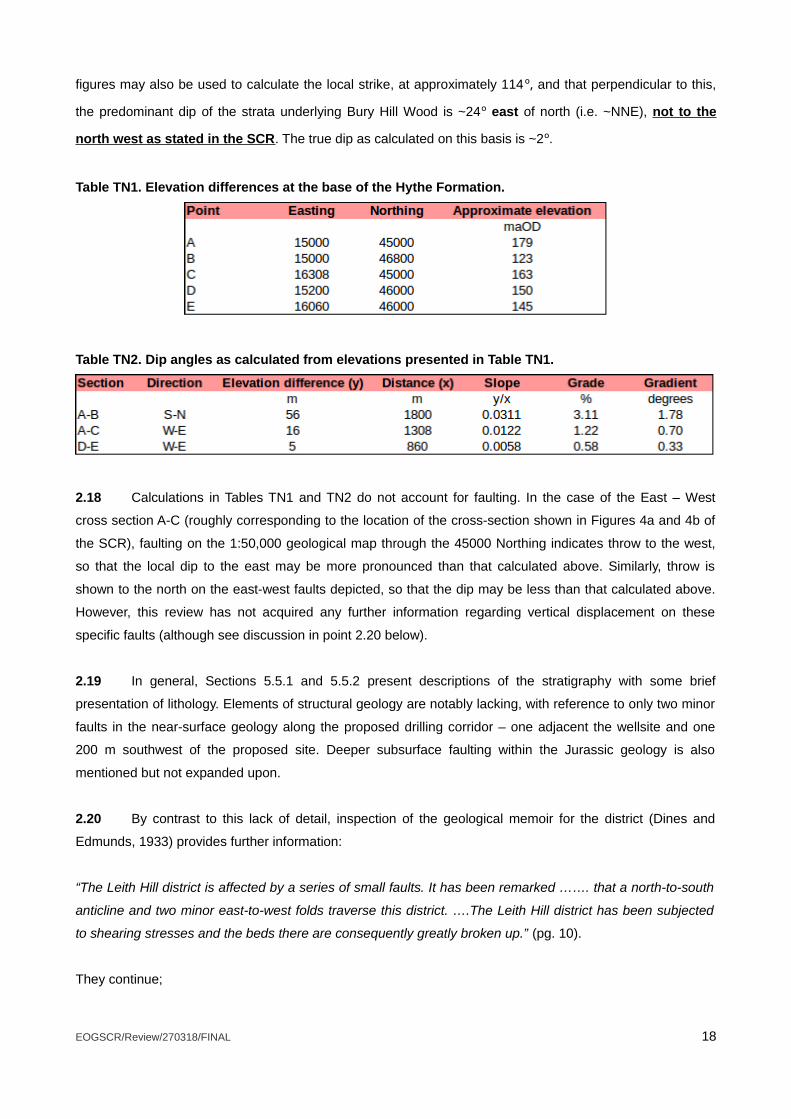
figures may also be used to calculate the local strike, at approximately 114º, and that perpendicular to this,
the predominant dip of the strata underlying Bury Hill Wood is ~24º east of north (i.e. ~NNE), not to the
north west as stated in the SCR. The true dip as calculated on this basis is ~2º.
Table TN1. Elevation differences at the base of the Hythe Formation.
Table TN2. Dip angles as calculated from elevations presented in Table TN1.
2.18 Calculations in Tables TN1 and TN2 do not account for faulting. In the case of the East – West
cross section A-C (roughly corresponding to the location of the cross-section shown in Figures 4a and 4b of
the SCR), faulting on the 1:50,000 geological map through the 45000 Northing indicates throw to the west,
so that the local dip to the east may be more pronounced than that calculated above. Similarly, throw is
shown to the north on the east-west faults depicted, so that the dip may be less than that calculated above.
However, this review has not acquired any further information regarding vertical displacement on these
specific faults (although see discussion in point 2.20 below).
2.19 In general, Sections 5.5.1 and 5.5.2 present descriptions of the stratigraphy with some brief
presentation of lithology. Elements of structural geology are notably lacking, with reference to only two minor
faults in the near-surface geology along the proposed drilling corridor – one adjacent the wellsite and one
200 m southwest of the proposed site. Deeper subsurface faulting within the Jurassic geology is also
mentioned but not expanded upon.
2.20 By contrast to this lack of detail, inspection of the geological memoir for the district (Dines and
Edmunds, 1933) provides further information:
“The Leith Hill district is affected by a series of small faults. It has been remarked ……. that a north-to-south
anticline and two minor east-to-west folds traverse this district. ….The Leith Hill district has been subjected
to shearing stresses and the beds there are consequently greatly broken up.” (pg. 10).
They continue;
EOGSCR/Review/270318/FINAL 18

“It appears more probable that the landslips here have taken place on account of the presence of the
disturbances in the strata, than that the disturbances are the result of landslips. Overthrust faults may be
seen in a series of quarries south of Redlands Wood where beds are overthrust from the east: those below
the thrust plane dip west at an angle of 45 °. … Holmbury Hill (does not) show signs of disturbance or land-
slipping while around Leith Hill disturbance of beds occurs over a considerable area.”
“An anticlinal fold …… with an axis slightly west of north through east of south through Leith Hill was
mapped by D Leighton”. (pg. 9).
Their text is not wholly clear as to whether their detailed mapping in the Leith Hill supports the existence of
this fold, though they continue:
“In the Leith Hill area ….. roughly east-to-west faults near Westlees Farm and Collickmoor Farm respectively
have downthrows to the north; … several small faults have been mapped around Pasture Wood and Leith
Hill, many of which have throws of but a few feet…” (pg. 11)
2.21 The latest 1:10,000 geological mapping has been brought to our attention and appears to show
much more extensive Quaternary deposits to the north and north-west of the Lower Greensand outlier on
which the proposed site is located, than presented on the 1:50,000 mapping (dated 1933) which forms the
basis of the geology reported within the SCR (Rev. 4) document.
• The situation of these deposits suggests potential direct hydrogeological connection between the
outlier and the main body of the aquifer utilised for public supply at Dorking but is not reviewed or
presented within the application.
• The Environment Agency is urged to review the most up-to-date 1:10,000 mapping available, for
example through EDINA.
2.22 Section 5.5.2, pgph 9, pg 16. This discussion presents an argument for the lack of permeability of
the Hastings Beds on the basis that no drilling losses were encountered whilst drilling through them in an
offset well (at a distance of approximately 10 km from the site). This is not an acceptable argument for
establishing the permeability of the formation in question because:
There is no discussion of the transferability of these results from one site to the next.
Whilst drilling mud losses might indicate significant void spaces in fissured or karstic zones, from
which one may then infer high permeabilities, that losses were not encountered does not guarantee
that the intergranular permeability is not significant.
Permeability (strictly speaking, hydraulic conductivity) is in any case a function of the viscosity of the
fluid as well as properties of the rock; this important factor is completely ignored.
Parts of the Hastings Beds are used as productive aquifers for public and private water supply
purposes in parts of East Sussex and Kent. By reasonable inference, the hydraulic conductivity is
likely to be sufficient for groundwater movement in the vicinity of the proposed Holmwood wellsite.
EOGSCR/Review/270318/FINAL 19

2.23 It is claimed that the interpretation of low permeability on this basis (point 2.22 above) is in
accordance with findings of the hydrogeological risk assessment and conceptual model in Appendix 3 (of the
SCR (Rev. 4) document. The findings in Appendix 3 are also problematic and are discussed further in
Section 3 of this Technical Note.
2.24 Section 5.6, Hydrogeology, pgs 21-22, will be discussed in detail in Section 3 of this Technical Note.
2.25 Section 5.7, Soils, pg. 22. “A number of shallow geochemical boreholes will be excavated during
the site construction phase. These boreholes will confirm the average depth and condition of the near
surface geology.”. By boreholes is actually meant hand-augered soil samples (Appendix 7). The conflation of
the terminology (and method, as one does not excavate a borehole) suggests a lack of knowledge on the
part of the principal authors of the SCR. The term ‘boreholes’ is not used by the authors of Appendix 7.
2.26 Section 5.7, Soils, pg.22 further establishes that “The testing of soils is for surface contamination,
therefore, on this basis, the absence of any contamination at the formation level will determine that the
ground below is also contaminant free,” This assertion does not always follow, such that contaminant plumes
can develop at depth that may not be present at the near-surface. Further, the sample is to be taken 300mm
below the [geological] formation level – i.e. within the bedrock - yet the text refers to the soil zone and field
soil sample testing techniques.
2.27 Section 5.8, Surface Water and Site Drainage, pgs 23-25. Calculated volumes of storage have
been discussed in points 2.8 – 2.13 and inconsistencies noted.
2.28 Section 5.8, Surface Water and Site Drainage, pg 23. “The proposed Holmwood wellsite will
provide complete primary containment for the operations which will take place within the wellsite. In addition,
where temporary oil storage is required, secondary containment bunding will be constructed above the
existing wellsite surface using railway sleepers and Bentofix GCL membrane to form a sealed containment
area.”.
2.29 The Applicant is directed toward CIRIA report C736 - Containment systems for the prevention of
pollution (CIRIA, 2014), in which definitions of primary, secondary and tertiary containment are provided (in
contrast to the usage presented in the quotation in point 2.28). Recommendations regarding construction
and monitoring standards for types of containment are also made. Neither the terminology nor the
recommendations have been implemented in the SCR. Indeed, no reference to CIRIA C736 is made at any
point in the SCR (Rev. 4) document.
2.30 For example, no calculations are presented for the volume of either secondary or tertiary
containment as recommended in CIRIA C736. 110% of primary containment volume is insufficient to meet
the requirements of CIRIA C736, especially for the storage of oil on site. There are additional requirements
(CIRIA, 2014). Although the Control of Pollution (Oil Storage)(England) Regulations 2001 (the Oil Storage
Regulations) allow for 110% bunding; bunding using the 110% principle is the minimum capacity that is
EOGSCR/Review/270318/FINAL 20
required and the alternative method presented by CIRIA is recommended where tanks in open bunds are
sited in locations with a greater risk, such as high rainfall areas, in more sensitive environments or greater
consequence of the oil stored entering the environment.
2.31 Section 5.8, Surface Water and Site Drainage, pg 24. “Additional areas used for the storage of
chemicals, oil based muds, produced water, NORM etc. will be constructed above the existing wellsite
surface using railway sleepers and Bentofix GCL membrane to form a sealed containment area or provided
by the installation of portable spill containment bunds.”
2.32 The use of ”...railway sleepers and Bentofix GCL membrane...” materials for construction of
secondary containment bunds for oil in particular are sub-standard due to:
• The flammability of the Bentofix GCL membrane and hence its durability, and;
• The risk of movement and stability of sleepers and hence the risk of leakage due to folds or tears in
the membrane.
2.33 Risk assessment methodologies for the selection of appropriate design criteria for containment
systems for pollution prevention are given in CIRIA C736 and should form the basis of the site design with
regards containment. The failure to incorporate these commonplace standards in site design is not
acceptable for a modern industrial facility.
2.34 Section 5.8, Surface Water and Site Drainage, pg 24. “The location of storage tanks, capacities
and secondary containment bunding is detailed within Appendix 8 of this Site Condition Report.” This is not
the case, however, and only storage capacities for the primary tanks are given, alongside materials
proposed for secondary containment.
2.35 Sections 5.9 (Groundwater Abstraction) and 5.10 (Water Quality) are discussed in Section 3 of this
Technical Note.
2.36 Section 7 (Baseline Monitoring) of groundwater is discussed further in Section 4 of this Technical
Note.
EOGSCR/Review/270318/FINAL 21
3.0 Hydrogeological Risk Assessment and Conceptual Model (Appendix 3 to the
SCR)
3.1 Although the Hydrogeological Risk Assessment and Conceptual Model appears as Appendix 3,
subsequent to the Groundwater Monitoring Strategy in Appendix 2, the strategy is necessarily informed by
the assessment and conceptualisation, so Appendix 3 is dealt with here first.
3.2 Appendix 3 runs from page 77 to page 135 of the SCR (Rev. 4) document, and includes three
technical notes in addition to the Hydrogeological Risk Assessment itself.
The main Hydrogeological Risk Assessment runs from page 86 to page 135.
The technical notes and the main Hydrogeological Risk Assessment are authored by Envireau Water
Ltd.
The main Hydrogeological Risk Assessment is reviewed prior to the technical notes.
Page numbers referred to herein refer to page numbers of the SCR (Rev. 4) document, whereas
section numbers and headings are those as given in the technical notes and report.
3.3 Section 2.1, Location, pg 91. The site is stated as having an area of 8.5 ha. There is confusion
throughout the SCR (Rev. 4) document regarding the actual size of the site (see points 2.7 to 2.12 above).
3.4 Table 1, pg. 92. It is interesting to note that the mean drainage direction of all slopes within the
catchment of Pipp Brook is 20º, as this is very similar to the calculated azimuth of local dip of the geological
strata as determined from calculations presented in Tables TN1 and TN2 (24o, a difference of approximately
1%).
3.5 Section 3.1, pg 93 pgph 2. “Based on the topography and the permeable nature of the underlying
geology at the wellsite, this means that only a small proportion of surface water will drain west towards Pipp
Brook, with a much more significant proportion of runoff generated is (sic) likely to infiltrate directly to ground;
providing baseflow to surface watercourses.” It is agreed that this is an important observation. However,
unlike surface water catchments, groundwater catchments do not necessarily conform to surface topography.
Given that such a high proportion of runoff from the site enters the groundwater system, it is all the more
important to establish a robust hydrogeological conceptualisation.
3.6 Section 3.2, pg 93 ‘Surface Water Features’ states “Whilst there are no mapped springs in close
proximity to the wellsite, it is reasonable to assume that a spring line may be present along the intersection
between the permeable sandstone bedrock (Hythe Beds) and the underlying mudstone (Atherfield Clay
Formation).”. It is noted here that:
Comparison of the geological and OS maps indicates some of the springs to be fault controlled, or
at least associated with faulting.
Comparison of the geological and OS maps indicates springs issuing from the base of the Atherfield
Formation.
EOGSCR/Review/270318/FINAL 22
No discussion of potential variations in groundwater level and its significance for hydrogeological
conceptualisation are presented in the Hydrogeological Risk Assessment and Conceptual Model,
which is a significant omission.
Silicification deposits, banded iron formations, ‘iron pans’ and cementation that form layers within
the Hythe Beds may all result in spring horizons at their outcrop.
Seepage rather than distinct springs may also be present on the Hythe Beds and Atherfield Clay
outcrops.
Please note that the terms ‘Hythe Beds’ and ‘Hythe Formation’ are used interchangeably throughout
the risk assessment and this Technical Note.
3.7 Section 4, pg. 94 ‘Geology’. “Excerpts from the geological maps and information provided by the
client are presented on Figure 2a and 2b.”. There is only a Figure 2 presented, no Figure 2a or 2b. Figure 2
is an excerpt from the 1:50,000 geological map. Information provided by ‘the client’ appears to extend to the
wellsite outline and shape of the drilling corridor.
3.8 Section 4.1.2, pg. 94, pgph 1: “The Folkestone and Sandgate Formations comprise predominantly
loose sands and sandstone with subordinate amounts of siltstones, mudstones and limestones...”. as
mentioned in point 2.15 above, what is meant is to give a description of the Folkestone and Hythe
formations, not the Folkestone and Sandgate formations”. It is material to highlight this typographical error,
as it is important that the Hythe Formation (assuming that is what is intended) is known to be highly silicified
in places and thus a competent bedrock; and should not be considered as “...predominantly loose sands and
sandstones...”.
3.9 As the Folkestone Formation is completely absent at the site, it would be more appropriate to
describe the Hythe Beds rather than a lumped description together with the Folkestone Formation.
3.10 Plate TN1 shows a photograph of a specimen of fine-grained, competent and silicified sandstone
representative of the Hythe Beds, Lower Greensand, obtained from approximately NGR TQ 15300 44600,
approximately 200 m to the south west of the wellsite. Although this is a partially weathered specimen, the
sharpness of the freshly broken faces indicates the high level of silicification.
3.11 The above distinction regarding the lithology of the Hythe Beds is important for a number of
reasons:
It is likely that the presence of the eastward-facing escarpment of Bury Hill Wood is due to greater
competence of the Hythe Beds in this area than to the east. Greater competence is due to a greater
degree of silicification than in the (now eroded) Hythe Beds to the east.
Greater competence of the Hythe Beds increases the likelihood of faulting due to cambering. It is
noted that the situation of competent sandstone over less competent Atherfield Clay and Weald Clay
adjacent to valleys and escarpments is suitable for cambering of the Hythe Beds (and potentially
valley bulge in the clays underlying the valley of the Pipp Brook).
EOGSCR/Review/270318/FINAL 23

Greater silicification and competence of the Hythe Beds means that joints, fractures and faults,
where they occur, may dominate, or at least significantly influence, groundwater flow.
3.12 Some springs in the vicinity of the site have already been noted (point 3.6 above) as controlled by
faulting, as for example at NGR TQ 16010 44530.
3.13 Section 4.1.2, Bedrock Geology, pgph 2, pg. 94. The Weald Clay Formation is described as “...a
thick sequence of mudstones...”. This extremely brief description is augmented by a description in Table 2
(Expected Hydrogeological Sequence), where it is described as “Dark grey thinly-bedded mudstones
(shales) with subordinate siltstones, fine- to medium-grained sandstones and ironstones.”
3.14 The BGS Lexicon of Named Rock Units1 describes the Weald Clay Formation as “Dark grey thinly-
bedded mudstones (shales) and mudstones with subordinate siltstones, fine- to medium-grained
sandstones, including calcareous sandstone (e.g. Horsham Stone Member), shelly limestones (the so called
"Paludina Limestones") and clay ironstones.”
3.15 It therefore appears that the Envireau Water description in their Table 2 has adopted verbatim the
BGS description of the Wealden Clay Formation, excluding the reference describing the presence of
limestones. As is widely understood in the field of hydrogeology, where dissolution of limestones plays a role,
limestones have the greatest hydraulic conductivity of any type of bedrock. Of course, this may not be the
case in the ‘Paludina’ limestones, but it is a failure of the risk assessment to not incorporate these potentially
highly permeable beds and to dismiss the possibility without further examination.
3.16 It is understood that the Hastings Beds and the Ashdown Beds are used for small scale domestic
water supplies locally and for public water supply purposes on their outcrop on the Weald of Kent and East
Sussex where they occur at the surface. Figure 5b of Appendix 2 (Scheme of monitoring for exploratory
hydrocarbon borehole, pg. 64) clearly illustrates a number of private water supplies and other wells situated
on the Wealden Group, although the British Geological Survey well record does not include depth of geology
therefore does not confirm from which of the Wealden Group beds the abstraction derives. Field
measurement of each of the boreholes identified in the BHS Well Index could confirm depth and indication of
whether in the Weald Clay, Tunbridge Wells Sands and Hastings Beds (Including Ashdown Beds). Envireau
Water have not undertaken this assessment.
3.17 Figure 2 (pg. 122) illustrates some of the variations in the Weald Clay. BGS map sheet 286, which
forms the main part of Figure 2, represents the Weald Clay as a monolithic brown unit. However, the insert
from BGS map sheet 302 below it, and the stratigraphic column in the upper right of Figure 2, both illustrate
the frequency with which the more permeable beds within the Weald Clay occur. The entire scanned map
sheet 302 is freely available on line at http://www.largeimages.bgs.ac.uk/iip/mapsportal.html?id=1001794
1http://www.bgs.ac.uk/lexicon/lexicon.cfm?pub=WC accessed 18/3/2018
EOGSCR/Review/270318/FINAL 24
and confirms this picture of widespread and common occurrence of both the Paludina limestones and the
coarser sandstone beds within the Weald Clay.
3.18 Beneath the Weald Clay, the Hastings Beds comprising the Upper Tunbridge Wells Sands, the
Grinstead Clay, the Lower Tunbridge Wells Sands, the Wadhurst Clay and the Ashdown Beds. The
distinction between the Upper and Lower Tunbridge Wells Sands separated by the Grinstead Clay (or locally
named clays) is not made. The Ashdown Beds is characteristically highly variable cyclothymic sand, silt and
clay deposits with intergranular groundwater flow, and localised perched groundwater and groundwater
lenses at outcrop, fractures, silicified and cementation deposits affecting groundwater movement.
3.19 Section 4.1.2, Bedrock Geology, pgph 5, pg. 94. “The geological maps for the region record the
presence of two minor faults along the proposed drilling corridor. A minor fault present on the eastern
boundary of the site displaces strata down towards the west. 200m from the site south west along the drilling
corridor a minor fault downthrows strata towards the north. Data provided by the client indicates the
presence of deeper, subsurface faults within the Jurassic age strata.”
3.20 Besides the two near-surface faults noted in the immediate vicinity of the wellsite, the BGS
1:50,000 mapping indicates several other faults in the Lower Greensand outlier on which the site is situated.
The 1:10,000 digital mapping shows additional faults in this block, and from both the topography and the
geological mapping and memoir it appears likely that there are others which have not been mapped.
3.21 Section 5.1, Aquifer Potential, Lower Greensand Group, pgphs 3 to 6, pg 96:
“The aquifer properties of the Hythe Formation are controlled by cementation of the sands and sandstones.
Where the formation is well cemented, flow is predominantly via fractures while where cementation is poor
flow is generally intergranular [Ref. 12].
The Hythe Formation at the site is unconfined and is underlain by mudstones of the Atherfield Clay
Formation, which based on the description provided by the BGS [Ref. 12] is considered as Unproductive
strata by Envireau Water on a regional scale.
There is limited published information available on groundwater levels within the Hythe Formation however
based on a review of the location of relevant springs and streamlines within the area, their topography and
underlying geology, Envireau Water expect groundwater levels to be approximately 25 metres below ground
level.
The regional groundwater flow direction is expected to be northwards and locally, flow direction is expected
to be variable on account of topography and surface water features. Groundwater flow directions in the
Hythe Formation in the vicinity of site are likely to be westwards towards Pipp Brook.”
EOGSCR/Review/270318/FINAL 25
3.22 The quotation given in point 3.21 above constitutes the entire discussion of the mode of
groundwater flow in the Hythe Beds. There is no discussion of the following basic hydrogeological
parameters:
porosity (total and effective)
hydraulic conductivity
transmissivity
storage
recharge
hydraulic gradient
groundwater velocity
seasonal variations in groundwater level
seasonal variation in groundwater divides and groundwater catchment boundaries
likely groundwater quality
heterogeneity
anisotropy
The report also fails to discuss relevant contaminant transport parameters, physical and geochemical
mechanisms within the Hythe Beds, structural influences such as folding, faulting or cambering, aquifer
mineralogy and geochemistry, or any kind of water balance or mass balance.
3.23 The lack of characterisation employing fundamental hydrogeological descriptors as listed above is
remarkable. Without such a discussion, it is not possible to formulate a robust conceptualisation on which to
base and qualify a site-specific risk assessment. Furthermore, the design of the monitoring programme and
the development of the risk assessment are built on the robustness of the conceptual understanding. A
poorly constructed and poorly substantiated conceptual model leads to poor monitoring design and limits
interpretation of data. Inclusion of a quantitative mass balance built on a sound conceptual model can lead to
robust hydrogeological understanding. The absence of the presentation of a sound hydrogeological
conceptual understanding in the supporting information results in inadequacies in monitoring design, risk
assessment and risk mitigation.
3.24 The justification for adopting a qualitative risk assessment, of the form presented in Appendix 3, is
that there are few or only insignificant uncertainties in our state of knowledge regarding the hydrogeology.
3.25 However, there is no acknowledgement of any uncertainties or possible lack of information. The
words ‘uncertainty’ or ‘uncertainties’ do not appear at any point in Appendix 3.
3.26 No risk screening exercise is either conducted or discussed to determine the appropriateness of
the level of risk assessment adopted. Nor are any basic scoping calculations supporting qualitative
assessment made. These omissions are in direct contrast to recommendations made in both the DEFRA
EOGSCR/Review/270318/FINAL 26
(2011) Green Leaves III and the Environment Agency’s H1 Environmental Risk Assessment framework –
Annex J (Groundwater) documents, which are stated as being the guiding principles by which the risk
assessment is conducted (Section 1.2, pg. 91, point 6; Section 7.1, Hydrogeological Risk Assessment –
Assessment Methodology, pg. 104).
3.27 Both of the documents cited in point 3.26 above present detailed discussions of the treatment of
uncertainty and how this informs the choice of risk assessment methodology and how risk screening and
scoping calculations should be employed to do so. None of this material has been brought into the
discussion presented in the Appendix 3 risk assessment, or indeed anywhere else in the SCR (Rev. 4)
document.
Fundamentally – the appropriate methodologies have not been applied, despite claims to the
contrary. Upon closer inspection, those claims prove to be unsubstantiated
The following points will discuss the hydrogeological understanding as presented by Envireau Water
in pgph 3-6 (given in point 3.21 above) in more detail.
3.28 It is unclear as to how the “limited published information available on groundwater levels within the
Hythe Formation” was assessed and addressed. Water level data and interpretation is held by the
Environment Agency, Water Companies and other third parties. Further, the Environment Agency has
recently undertaken the construction of regional groundwater models for the Lower Greensand aquifer and
for the Mole catchment. The early phases of this work have led to a detailed conceptual model built on the
collation of a large dataset. There is no reference to this regional model or an approach to the Environment
Agency to request data or information about the Lower Greensand conceptual model and the Mole
catchment conceptual model used to develop the respective numerical models. Therefore, due consideration
of the data available to the Environment Agency (and general public) has not been brought into the
Applicant’s supporting information.
3.29 It is furthermore unclear to what extent the Environment Agency have referred to their regional
groundwater model for the Lower Greensand in their decision to issue the draft consent.
3.30 Section 5.1, Aquifer Potential, Lower Greensand Group, pgph 3, pg 96. Fracture vs. fissure flow is
clearly relevant to potential contaminant transport and hence to risk assessment. The competence of the
Hythe Beds in the vicinity of the site has been discussed in points 3.8 to 3.11 above. It has been pointed out
that faults exist in close proximity to the site and elsewhere within the Lower Greensand outlier within which
the site is situated. However, none of this information is translated into or informs the hydrogeological
conceptualisation as presented.
3.31 Section 5.1, Aquifer Potential, Lower Greensand Group, pgph 4, pg 96. Here the conceptualisation
of the Atherfield Clay as Unproductive Strata is subsequently used to dismiss its potential role in contaminant
transport. Because it is ‘unproductive’, which means that on a regional scale it is not used for public water
supply, it later becomes one constituent of an effective hydraulic barrier (Section 5.5, Conceptual
EOGSCR/Review/270318/FINAL 27

Hydrogeological Model). However, as previously noted (point 3.6), and illustrated on Figure 5b of Appendix 2
(Scheme of monitoring for exploratory hydrocarbon borehole, pg. 64), springs are recorded as occurring at
the base of the Atherfield Clay.
3.32 Section 5.1, Aquifer Potential, Lower Greensand Group, pgph 5, pg. 96. “There is limited published
information available on groundwater levels within the Hythe Formation however based on a review of the
location of relevant springs and streamlines within the area, their topography and underlying geology,
Envireau Water expect groundwater levels to be approximately 25 metres below ground level.” This poorly
substantiated statement avoids any discussion of potential spatial or seasonal variation groundwater levels.
Further, the assertion is insufficiently robust for the purposes intended – that is to support an application with
known risks and uncertainties that need to be addressed and well presented.
3.33 Section 5.1, Aquifer Potential, Lower Greensand Group, pgph 6, pg. 96.
The statement “The regional groundwater flow direction is expected to be northward...” is
presumably based on the generally northward regional dip of the strata. However, as discussed in
point 2.17 above, the dip of the beds forming the outlier on which the wellsite is situated are
generally to the NNE. This has important implications for the hydrogeology, because this dip may
exert some control on flow within the aquifer.
“Groundwater flow directions in the Hythe Formation in the vicinity of site are likely to be westwards
towards Pipp Brook.”
◦ This statement is based solely upon an analysis of topography and fails to consider the faults
immediately adjacent the site to the east and south, and others potentially present as noted in
the geological memoir (see point 2.20 above).
◦ The faults east and south of the site run perpendicular to one another and may exert significant
control on groundwater flow direction. For example, the fault to the south of the site may well be
an extension of the fault mapped to the south of Redlands and which controls the occurrence of
springs at that location.
◦ Overall the significance of faults and other strata disturbances are that they may affect the
preferred direction of groundwater flow beneath the surface in the project area, because such
more heavily fractured zones in the bedrock are likely to be preferentially more permeable and
so potentially divert groundwater flow from a simplistic “downslope” pathway to the west or
“down-dip” pathway to the north.
Possible variations in groundwater flow direction at different times of the year are not discussed.
The “limited published information available on groundwater levels within the Hythe Formation” and a
dependency on springs, streamlines, topography and limited assertions about the underlying
geology (as presented in Section 5.1, Aquifer Potential, Lower Greensand Group, pgph 5, pg. 96)
cannot be considered sufficiently robust for the purposes of supporting the wellsite application. The
limitation of the assertion about groundwater level limits the design of the proposed groundwater
monitoring as it does not allow for sufficient triangulation and investigation into actual groundwater
movement and seasonal variability.
EOGSCR/Review/270318/FINAL 28
Quaternary deposits are noted on the latest 1:10,000 geological mapping with a significantly different
distribution to the Quaternary deposits as noted on the 1:50,000 geological maps used as the base
maps for the hydrogeological risk assessment. These need to be considered as they have
implications for the picture of a lack of hydrogeological continuity between the Hythe Beds at the site
with the Lower Greensand used for the Dorking water supply.
3.34 Section 5.1, Aquifer Potential, Wealden Group, pgph 3, pg. 97. “The Hastings Beds Formation
comprises the Tunbridge Wells Formation and the Ashdown Formations, both of which are classed as
Secondary aquifers at a regional scale and are separated by the poorly permeable Wadhurst Clay
Formation. Since the formations are located at a depth of approximately 445 to 745m at the site, the
permeability of the formation and ability to yield water is likely to (sic) limited.” pg. 97.
3.35 No justification is given for the supposed reduction of permeability at these depths, it is just stated
as a matter of fact. Permeability reductions with depth are a hydrogeological rule-of-thumb, due principally to
increased fracture closure with depth. However, rules-of-thumb cannot be accepted as site-specific facts
unless corroborated by some evidence, of which none is presented. It is also meaningless to state that
permeability is “...likely to be limited.” as even the most permeable formations exhibit permeability limits.
3.36 Section 5.1, Aquifer Potential, Wealden Group, pgph 4, pg. 97. “Given the distance of the outcrop
from the site, the depth of the formation and reduced permeability, any water present within the Hastings
Beds at the site is likely to be old and therefore of a poor quality, with minimal resource value… This is
consistent with data presented in Section 5.2, which shows there are no abstractions within 5km of the site
that are targeting the Hastings Beds.”
3.37 Part of this argument (point 3.34) relies upon the claim that a reduction in permeability is
responsible for a reduction in water quality. This is spurious as, firstly the claim for a reduction in permeability
is unsupported by any evidence, and secondly a proportional relationship between permeability and water
quality is not an established hydrogeological relationship. There are plenty of examples of high permeability
formations with poor water quality, and vice-versa, because there are many other factors involved.
3.38 It is furthermore suggested that the poor water quality is demonstrated by the lack of wells
penetrating the formation, whereas the actual reason is that there are adequate resources closer to the
surface, hence no need to drill so deeply; poor water quality is entirely incidental to these circumstances.
3.39 The above criticisms are not intended to demonstrate that water quality in the Hastings Beds is not
poor at the depths discussed. It may indeed be, and it is agreed that the arguments of distance to outcrop
and likely high residence times mitigate against the resource being of significant quality. The point is that the
discussion as presented illustrates significant weaknesses both in knowledge of hydrogeological processes,
and in the use of reason and argument. These failings are unacceptable in the delivery of risk assessments
for oil wells situated on principal aquifers.
EOGSCR/Review/270318/FINAL 29
3.40 Section 5.5, Conceptual Hydrogeological Model, pg. 100.
Various uncertainties with respect of geological and hydrogeological understanding have been
detailed throughout Sections 2 and 3 of this Technical Note.
Layer 2 is considered an effective hydraulic seal on the basis of its characteristics as a water
resource, not on its intrinsic properties. This is both logically and scientifically inadmissible.
Layer 3 is also subject to spurious argumentation and lack of rigorous definition (see points 3.34 to
3.39).
Lack of vertical movement of water between Layers 1 and 3 is not demonstrated, it is just assumed.
The claim of lack of vertical movement of water between Layers 1 and 3 dismisses any possibility of
regional groundwater flowpaths such as described by e.g. Tóth (1995).
Natural recharge to the formations in Layer 1 may well be limited to outcrop, but this is highly unlikely
in Layer 3 (see again Tóth (1995)).
There is no reference to conceptual models produced by others. The Applicant’s conceptual
understanding could have been compared with the conceptual model used in the Environment
Agency’s Lower Greensand Aquifer Model. Neither the Applicant nor the Environment Agency make
reference to such a comparison if it has been done.
3.41 The conceptual hydrogeological model is summarised in Figures 4a and 4b, pgs 124 – 125.
Figure 4a presents a fault as if it has been considered in terms of its influence on flow, but this
aspect of the conceptualisation has been overlooked.
In Figure 4b the dip of the Atherfield Clay beneath the site is shown to fall to the west, suggesting
flow down-dip toward Pipp Brook. This is completely wrong.
Also, on Figure 4b the fault intersecting the surface between the site and the brook has been left out,
which is a significant omission.
The hydrostratigraphic units are questionable as discussed in the previous point.
3.42 Section 5.5, Conceptual Hydrogeological Model, pg. 100. “The lateral variation in geology is
controlled predominantly by dip and faulting.” This is a puzzling addition to the conceptual model as these
aspects have not been discussed in any detail under the sections describing geology or hydrogeology, and
indeed are conspicuous by their absence.
3.43 Section 6, Proposed development and water management at the wellsite, pg 101.
Table 3. The area of the site is stated as 0.5 ha. Perhaps this is what Envireau Water meant
previously, but it still does not agree with other parts of the SCR (Rev. 4) document.
Appendix A is referred to. Scrutiny of Appendix A shows that all of the topographic information for the
site is incorrect, as it shows the majority of the site to be between 235 and 238 maOD in elevation.
This is wrong as it is inconsistent with OS map contours.
EOGSCR/Review/270318/FINAL 30
The specification for the surface of the wellsite presented in Appendix A is also in disagreement with
other parts of the SCR (Rev. 4) document, such as, for example, Figure 5.1 on pg. 11. This
constitutes a further error.
It is noted that the drilling method has changed since the main hydrogeological risk assessment was
written. Details regarding drilling will be dealt with in Section 5 of this Technical Note.
3.44 Drainage and water management have already been discussed under points 2.7 to 2.13 above.
3.45 Section 7, Hydrogeological Risk Assessment, pg. 104. “A hydrogeological risk assessment for the
proposed development has been carried out in accordance with GL III using the Source-Pathway-Receptor
(S-P-R) methodology described in the Environment Agency’s H1 Environmental Risk Assessment framework
– Annex J (Groundwater)”.
As discussed in points 3.24 to 3.27 there are major failings with regards to the implementation of
methodological recommendations as outlined in the cited methodologies. On these grounds the
appropriate level of risk assessment to address outstanding uncertainties has not been identified (or
even discussed). The resultant arbitrary selection of the simplest (i.e. qualitative) risk assessment
method remains unsubstantiated.
This coupled with the failure to present basic hydrogeological information and hence a failure to
describe the groundwater system in anything other than the most rudimentary detail, mean that the
risk assessment is not fit for purpose.
3.46 There are many points within the risk assessment summary tables (Table 8, Appendix 3, SCR Rev.
4 document) where unjustifiably low risk ratings have been used. There are various industry documents such
as the Amec Foster Wheeler (2016) ‘Study on the assessment and management of environmental impacts
and risks resulting from the exploration and production of hydrocarbons’ where levels of risk remain
moderate to high even following mitigation.
3.47 A more detailed overview of the risk assessment methodology employed, alongside literature
review of current industry standards and research into uncertainties surrounding onshore oil and gas
operations, is given in Section 6.0 of this Technical Note.
3.48 However, a couple of notable points stand out. For example, in Section 7.3.2, Magnitude of Impact,
pg. 107 it is stated that “Given the scale and temporary nature of the development, if Pipp Brook or
groundwater within the Hythe Formation became contaminated during wellsite construction and restoration,
the impacts would be considered minor and therefore the magnitude of impact would be low.”
Referring to Table 5 (pg. 105), a ‘Low’ magnitude of impact is defined as ‘results in minor impact to
attributes.’. Thus, paraphrased, what the above statement actually says is: ‘Because impacts are
considered minor, they are considered low.’ (and vice-versa.). This is both spurious and absurd.
Despite the logical challenge to the argument, it may further be observed that a small-scale and
temporary development may not have the probability of occurrence of an initiating event, but that is a
EOGSCR/Review/270318/FINAL 31

different matter to the impact of it. It is notable that no boundaries are attempted with regards to what
magnitude of e.g. fuel spillage (a hazard listed under wellsite construction in Table 7) might be
required to cause ‘low’ ‘medium’ or ‘major’ impacts. Throughout the risk assessment, there is an
absence of boundaries; meaning no attempt has been made to quantify the risks, leading to an
inadequate presentation for the purposes intended.
A lack of quantification and a failure to demonstrate understanding of the hydrogeological situation,
shows that it would be more appropriate to adopt a precautionary approach.
A precautionary approach would have, for example, a major vehicular diesel spillage entering directly
a fracture, traversing the unsaturated zone in short order to hit groundwater flowing at high velocity
along a fault to arrive within days at a private supply well, or worse still, the Lower Greensand aquifer
feeding the Dorking public water supply via Pipp Brook. Therefore, the question is: Why is this
scenario not realistic? And the answer is that we don’t know whether it’s realistic or not because
there is not sufficient qualified and quantified understanding of the hydrogeological conditions on
site, as amply demonstrated throughout this Technical Note (but in particular with reference to basic
hydrogeological parameters).
Thus, the dismissal of risk in this way implies a claim by the Applicant that ‘nothing can go wrong’
and should be rejected as such. Adoption of a precautionary principle and a drive for further data
collection and evaluation to improve the hydrogeological understanding is considered essential to
avoid poor decisions with regards to this application.
3.49 Section 7.4, Embedded mitigation, pg. 107. Review of research into risks associated with onshore
oil and gas production has been conducted as part of the scope of works of this review, and the results are
presented in Section 6.0 of this Technical Note. However, it is clearly relevant to ask why are 22-year-old
regulations designed for a completely different scenario (i.e. offshore installations) being applied to regulate
an onshore development.
3.50 Envireau Water Technical Note dated 08/09/17 deals with water management. As has been
previously discussed, due to inconsistencies in site area and design, and due to a failure to account for
recommendations in CIRIA C736, these calculations are unacceptable.
3.51 Envireau Water Technical Note dated 07/07/17 deals with alterations in design of the exploratory
hydrocarbon borehole. Details of borehole construction will be addressed in Section 5 of this Technical Note.
3.52 There is no consideration within the Applicant’s supporting information whether there is interaction
between the Pipp Brook and the aquifer units it flows above; and whether the stream has gaining and losing
reaches along its length. Measurement of flows along the length of the Pipp Brook to determine seasonal
accretion profiles throughout the year would aid this assessment and inform the quantitative mass balance
and conceptual understanding. The absence of accretion profiles or the recommendation to undertake field
measurements to test and validate a hydrogeological conceptual model is amiss. It is highly recommended
EOGSCR/Review/270318/FINAL 32

that accretion profiles derived from field measurement over the course of at least one year are included to
validate the conceptual understanding and risk assessment.
EOGSCR/Review/270318/FINAL 33
4.0 Groundwater Monitoring Strategy (Appendix 2 to the SCR).
4.1 Despite the purpose of a Site Condition Report being to report on actual conditions at the wellsite,
there is a complete absence of site-specific groundwater data. It is noted in this context that the Applicant
has had a decade in which to acquire such information and has not provided it in support of the application.
4.2 In lieu of any actual site-specific data relating to the condition of the site, the SCR (Rev. 4)
document states in various places that data are due to be collected. It is understood that, at the time of
writing this Technical Note (March 2018), some samples have been taken. However, results from the
analysis of these samples have not been made available as part of the consultation, and the quality of the
data cannot be assessed.
4.3 Appendix 2 consists of the main Scheme of Monitoring for Exploratory Hydrocarbon Borehole and
an ancillary Technical Note responding to comments made by Peter Brett Associates and dated 22/09/16.
The main scheme of monitoring will be dealt with here first.
4.4 The scheme of monitoring reiterates the geological and hydrogeological setting as laid out in
Appendix 3. These have been reviewed in Section 3 of this Technical Note and will not be repeated here.
4.5 Section 2, Site Setting, pg. 41. The area of the site is now reported as 0.35 ha; inconsistent with
other values of the reported area of the site.
4.6 Section 4.6, Source Protection Zones, pgph 2, pg. 49. “The Dorking public water supply boreholes
are located a considerable distance from the wellsite and, as discussed in the HRA [Ref. 3], they are not
considered to be at risk from the development.”.
This an incorrect statement. The HRA lists the Lower Greensand in SPZ2 of the Dorking public water
supply abstraction as at risk of contamination of Pipp Brook.
4.7 Section 4.7, Field verification. “There is a well at Highlands (C3) that is used for private water
supply. Given the location of similar supplies in closer proximity to the wellsite (C1, C2, D1), monitoring is not
necessary.”
Envireau Water continued to contact the owner at Highlands for access to their water supply, and
obtained water samples from that location on 21/07/18 and 18/08/18. This appears to be in
contradiction to their statement that monitoring at this location is not necessary.
No details of sampling methodology associated with these samples have been identified by this
review.
4.8 Section 4.7, Field verification, pg. 50. “The springs at A3, A4, and A5 comprise boggy ground. The
springs are located in thick undergrowth and there are no suitable monitoring locations close to the sources.
The other water nearby features are more suitable for monitoring.”
EOGSCR/Review/270318/FINAL 34
It is not true that there are no suitable monitoring locations close to the sources. The northernmost of
the springs marked on Figure 5a at point A4 is located in an area of spring resurgences, one of
which emerges onto a footpath at NGR TQ 16023 44625.
The series of springs marked as A3, A4 and A5 are, on the grounds of both topography and geology,
potential receptors of contamination arising at the wellsite. Therefore, a proper evaluation of the risk
posed to these springs is required within the Applicant’s supporting information.
The observation by the Applicant implies areas of seepage around each spring. Downstream flow
measurements in the field can determine total flows from the springs and seepage. Such
measurement to verify flows has not been undertaken by the Applicant.
The observation of ‘boggy ground’ has not been qualified in terms of time of year, seasonal variation,
rainfall conditions at the time and whether any spring capture structure was once present that has
deteriorated and no longer holds water.
It is claimed that other nearby receptors are more suitable for monitoring, but in fact the sampling
points at F3, F5 and F6 all sample water from distribution systems, leaving F4 the only sampling
location located at the actual source. As this is a large domestic well open to the atmosphere it will
be challenging to purge it of the necessary volumes of water necessary in order to obtain suitably
representative groundwater samples.
It is unlikely that any of the monitoring points F3, F4 or F6 will be representative of groundwater
conditions.
4.9 With regards the Pipp Brook (north) monitoring point at F2, it is questionable that this location is
entirely north of the potential area of influence of wellsite.
One potential pathway from the site to Pipp Brook is northward along the N-S fault adjacent to the
site, followed by discharge into the minor NW-SE valley the head of which is located at
approximately NGR TQ 15555 45255.
The possibility of northward groundwater flow is admitted by Envireau Water inasmuch as they
consider the groundwater at F6 to be a potential receptor. Such a path is much more likely to be
intercepted by the valley mentioned above than by the Collickmore Farm source, and may be missed
by sampling both at F2 and at F6.
4.10 Section 5.1.2, Offsite water features, pg. 53. “Given the confidence in the local geological setting
and that water monitoring boreholes will be installed at the wellsite, it is not necessary to incorporate water
features at a greater distance from the wellsite within the scheme of monitoring.”
This hubristic statement is made against a background of failing to acknowledge any uncertainties in
the state of knowledge regarding the site.
Such certainty using such a limited data set is antithetical to scientific understanding, and should be
regarded with considerable caution.
EOGSCR/Review/270318/FINAL 35

4.11 Section 5.2, Monitoring Parameters, pg. 54. “Water sampling and field and laboratory analysis will
be carried out in accordance with the requirements of an environmental permit and will include, but not
necessarily limited to, the parameters listed in Table 8.
Key indicators of additives used during the drilling and testing operations will also be added to the list of
parameters once they are established as part of the environmental permitting process.”
Additives proposed for use during the drilling and testing operations are already understood and
have been declared in the document ‘Europa Oil and Gas (2017) Holmwood Wellsite Drilling
Products Exploratory Borehole, document no. EOG-EPRA-HW-DP-009’ as part of the consultation
process.
Given that this is the case, why have the determinands to be monitored not been presented within
the scheme of monitoring? There has been ample time for this to occur.
4.12 Section 5.3, Monitoring frequency, pg 55. “Monitoring will be carried out in accordance with the
requirements of an environmental permit. The frequency of baseline monitoring will be at least monthly.
Baseline monitoring will be carried out for at least three months before the development commences.”
This period of baseline monitoring is inconsistent with establishing a natural baseline, for which at a
minimum one hydrological year’s worth of data are required.
This period of monitoring is also inconsistent with other areas of regulated consented activities by
the Environment Agency. For example, where a groundwater abstractions licence may have the
potential for significant adverse impact, the Environment Agency may expect a more extensive
period of monitoring and assessment in terms of impact on the aquatic environment aligned with the
requirements of the Water Framework Directive. As the proposed development has the potential for
significant adverse impact, it is reasonable to expect a minimum of a period of one year of baseline
monitoring to support this application. The minimum of one year monitoring period is to include the
annual hydrograph.
4.13 The following points are made with regards the Technical Note dated 22/09/16 in response to Peter
Brett Associates.
4.14 Section 2, PBA Comment ii, pg. 35. “The expected groundwater flow direction in the Hythe
Formation at the Well Site is west towards the Pipp Brook. Since the springs at Redland Wood are over 1 km
north east of the Well Site, there is no plausible pathway for groundwater to migrate from the Well Site
towards them and consequently there is no sound technical justification for them to be incorporated in the
scheme of monitoring.”
The principal technical justification for monitoring a spring to the north east of the site is that the
principal dip of the strata beneath the site are in that very direction. However, the authors have not
been sufficiently astute to deduce this from the available data.
The above statement also ignores any possibility that the N-S oriented fault immediately adjacent the
site might have any influence on groundwater flow.
EOGSCR/Review/270318/FINAL 36
A great deal of certainty is claimed for a site where not even the most basic hydrogeological
parameters have been established.
It would be more appropriate to acknowledge that there are uncertainties and attempt to address
them, rather than dismiss them on the basis of a spurious claim to knowledge.
4.15 Section 3, Summary, pg. 36. “The PBA comments do not challenge the hydrogeological conceptual
model or the approach to monitoring.”
The PBA statement that they are “...unclear why the springs in Redland Wood; to the south-west of
Redlands Farm, have not been included in the water features survey and recommend that they are
considered for monitoring or that one of the wellsite monitoring boreholes is located on the northeast
edge of the wellsite” represents a clear challenge to the conceptualisation as stated by Envireau
Water. PBA can clearly see that failure to monitor in a north-easterly direction is an omission on the
part of the monitoring. As discussed in the previous point this has not been adequately addressed by
Envireau Water.
EOGSCR/Review/270318/FINAL 37
5.0 WR11 Notification document (Appendix 4 to the SCR)
5.1 The WR11 Notification document forming Appendix 4 runs from page 137 to page 239 of the SCR
(Rev. 4) document.
5.2 As an additional appendix to the WR11 Notification, the entirety of the Hydrogeological Risk
Assessment, together with its ancillary technical notes and own appendices, are reproduced (from page 180
to page 239).
5.3 Indeed, multiple presentations of the same material are made throughout the SCR (Rev. 4)
document.
For instance, Figure 5a ‘Well Construction Concept’ appears throughout the document no fewer than
7 times (on pages 81, 84, 126, 179, 184, 187 and 229), in what appears to be at least two different
formats.
This degree of repetition needlessly lengthens, and significantly confuses, the entire SCR (rev. 4)
document. Overall, the document demonstrates:
◦ Lack of accurate pagination.
◦ Lack of an accurate Table of Contents.
◦ Frequent lack of consistency.
◦ Needless and excessive repetition.
These demonstrate a lack of basic presentational skills.
Such basic issues all serve to firmly support the impression of a lack of competence on the part of
the Applicant.
A less generous interpretation is that these issues serve to deliberately obfuscate the material to
make it less tractable to analysis.
This presents a major problem in terms of presenting the SCR (Rev. 4) document as part of a public
consultation, because, for the reasons given, it is not suitable for this purpose.
It is also questionable that the standard of the submission meets the Environment Agency’s
expectations for such applications and associated supporting information.
The one-month consultation is a wholly inadequate time period in which to robustly review and form
views on several hundred pages of technical material. Consequently, the Regulator’s role is
frustrated, as there is insufficient opportunity for an alternative technical viewpoint to be presented
and as such limiting the Environment Agency to make a fully informed objective assessment.
5.4 To continue with review of the WR11 document, the following statement is made in order to clarify
its purpose, repeated here to inform the subsequent review (Section 2, Scope, pg. 144): “Under Section 199
of the Water Resources Act 1991 (as amended by the Water Act 2003), a notice of the intention to construct
or extend a boring for the purpose of searching for or extracting minerals must be submitted to the
EOGSCR/Review/270318/FINAL 38
Environment Agency using form WR11. The WR11 requires that a method statement, including drilling and
casing designs, together with storage and use of chemicals and drilling muds, are included with the WR11
submission.”
5.5 Section 4 (Geological Setting), pgs 147 to 152.
This material is copied or was the source of the material presented on pages 14 to 20 of the SCR.
Parts of this section (Section 4) are also the same text as used to describe bedrock and site-specific
geology in the Hydrogeological Risk Assessment in Appendix 3.
It is unclear who has authored which pieces of text.
In particular, it appears that the hydrogeological consultant may be the author of the WR11 oil well
design, which would be odd considering they are neither petroleum geologists or oil well drilling
engineers.
Vice-versa, it is equally unclear whether or not Europa Oil and Gas are responsible for writing parts
of the hydrogeological risk assessment on behalf of their own environmental consultant.
5.6 A critical review of the geological and hydrogeological conceptualisation are made in Sections 2
and 3 of this Technical Note and will not be repeated here.
5.7 Section 5, Drilling Operations, pg. 154. “Over the 11 years to date, the borehole design has
changed to reflect evolving seismic interpretations and the availability of new offset well information,
including the HH1 exploration well drilled in late 2014. Raised formation depths and targets have, in turn,
necessitated changes to the well design, in terms of trajectory and casing scheme. As the proposed H1
exploration well is highly deviated, changes in prognosed formation depths strongly affect the well trajectory.
This would not be the case if H1 was planned to be a vertical or sub-vertical, as is the case with most
exploration wells.”
Based on the experiences of Europa Oil and Gas over the last 11 years, it seems more likely than
not that ‘prognosed formation depths’ could well change in the future.
It is noted here that the well trajectory is ‘strongly affected’ by changes in the prognosed formation
depths.
5.8 Section 5, pgph 6, pg. 154. “The June 2012 well design is taken from the expert witnesses Ian
Burdis Proof of Evidence, presented in the June 2012 Appeal.”
Europa Oil and Gas do not appear to have included their well design with their application, which
instead appears to have been drawn from submissions made as part of the public enquiry six years
previously.
5.9 Section 5, pgph 8, pg. 155. “The March 2015 well design is taken from the Regulation 22
Submission Mar 2015, in respect of the Environmental Statement November 2014, which has in the
Appendix to Chapter 12 the "Hydrogeological Risk Assessment, Land at Bury Hill Wood, Holmwood, Surrey"
EOGSCR/Review/270318/FINAL 39
report by Envireau Water March 2015. Figure 5a “Well Construction Concept” near the end of this report is a
sketch of the section view along the well trajectory from which the trajectory and casing/hole depths are
read. Reference is made to Figure 5a, as it is believed to be the last well design presented in the planning
process before planning approval was granted.”
That is to say, the “...trajectory and casing/hole depths” presented in what is purportedly “...a method
statement, including drilling and casing design” has been “read” from “...a sketch of the section view
along the well trajectory” as presented in the hydrogeological risk assessment.
This remarkable admission amounts to a statement by the Applicant that they do not know what
their own well design is, or where it came from and in lieu of such knowledge have resorted to
drawing upon a well design presented in the hydrogeological risk assessment.
As neither the actual design, nor its source, are clearly presented or without omissions, neither can
be regarded as admissible for the WR11 application.
5.10 Sections 5, 5.1 and 5.2 enter detailed discussion with regards drilling operations, the purpose of
which appears to provide technical justification for the use of oil-based drilling muds at a shallower depth
(177 m TVD-GL) than previously proposed (460 m TVD-GL).
5.11 Certain aspects of the discussion are highlighted below:
Pg. 156 “This 170mTV uplift makes the well much harder to drill, as the dogleg severity in the angular
build-up section has to be increased to the maximum allowable of 5°/30mMD, without any scope to
relax this in case of borehole instability while drilling through the Weald Clay. If this dogleg severity is
not achieved, the deviation angle of the subsequent straight hole section will exceed 70°, which in turn
precludes the use of slickline or wireline tools in the well, as the absolute upper limit for running such tools is
a wellbore deviation of 70°. Without wireline access it will not be possible to run back-up wireline logs (in the
event of problems running tubing conveyed logs), nor will it be possible to run the planned wireline casing
bond logs. In addition, without slickline access, it will not be possible to run plugs and operate Sliding Sleeve
Doors (SSDs) in the production testing completions.”
Pg. 157 “With the base of the Weald Clay at ca 400m TVD-GL (ca 180m TVD-SS), the greater length of
straight hole section at 67.6deg deviation in the Path 8 trajectory is obvious. As explained above, the
challenge of drilling this trajectory through the Weald Clay is far greater than for the June 2012,
December 2013 and March 2015 trajectories.”
Pg. 159. “A technical issue with the shallow kick-off and high an angular build rate proposed in the H1 well is
that the angular build section and the start of the straight hole section is completed within the Weald Clay.
This is highly unusual, resulting in drilling sub-horizontally at 67.6° through shallow clays, which are
highly prone to swelling and borehole instability upon chemical hydration. All the offset wells sought to
minimise or avoid borehole instability problems in the Weald Clay by drilling vertically or sub-vertically
EOGSCR/Review/270318/FINAL 40
through it, only attempting high deviations once beneath the Weald Clay. As stated previously, this is not
possible in the H1 well.”
Pg. 159 “In addition to technical issues associated with borehole stability during drilling, there are also
technical issues associated with borehole stability when running the 13-3/8” (339mm) surface casing.
Borehole cleaning becomes difficult at deviation angles between 45°-70° due to “avalanching”, where
small cavings off the borehole rock face fall down the borehole causing further cavings and eventually small
avalanches.”
5.12 The above textual highlights look very much like an admission that the wellsite is in the wrong
location with respect to the target formation. Whilst the wellsite may have looked like it was in a
reasonable location 11 years ago when the application was first made, later seismic and other data
interpretation have necessitated subsequent adoption of a technically extreme (i.e. at the very limit of what is
technically possible) and “highly unusual” drilling angle ‘without any scope for relaxation’ should ground
conditions prove to be other than anticipated. The location of the drill site therefore introduces additional risk,
establishes the drilling method at its limits and increases the risk of borehole construction and integrity
failures.
5.13 The regular reinterpretation of the data that has been undertaken by the Applicant over the years
implies problems with the data itself.
5.14 There is no discussion of the transferability of the HH1 offset data to the HW1 well itself. The HH1
Well is ~10 km distance from the HW1 site/target. There is likely to be a considerable degree of faulting and
variation in lithology that is unaccounted for between the two sites. This uncertainty and associated risk is not
characterised in the application.
5.15 Further, a successful cement bond within the cased borehole may be jeopardised because of its
sharp angle. The increased length of the borehole to the target also increase the risk to attaining a
successful cement bond. Breaches, voids and microannulus in the cemented casing can place undue
pressure on the integrity of the borehole and exacerbate risk of seepage or leakage from the borehole into
the bedrock geology and jeopardise the hydraulic efficiency of the primary cementing operation. Proposals to
survey the borehole to demonstrate a successful cement bond has not been presented in the WR11
proposal, which is a significant omission.
5.16 On the grounds of points 5.11 to 5.14, it seems that the level of uncertainty has not been
characterised and may, thus, undermine the case for adopting drilling techniques that are admitted by the
Applicant to be at the very limit of their technical capabilities. This does not appear to be a recipe for
successful operation.
5.17 Section 5.2, Pg. 161. “If mud density and chemical composition is not properly maintained due to
poor mud engineering or logistical problems with supply of chemicals...”
EOGSCR/Review/270318/FINAL 41
This issue is not identified as a hazard anywhere in the risk assessment documentation, and no
mitigating measures have been proposed.
5.18 Section 5.3, Pg. 163. “Primary well control during the drilling of the H1 well is achieved by
maintaining a hydrostatic pressure within the well, exerted by the column of drilling fluid, designed to ensure
a hydrostatic pressure greater than the anticipated pressure of the formation being drilled. It is commonly
referred to as ‘overbalance’. It is fundamental to ensuring compliance with Regulation 13 of the Offshore
Installation and Wells (Design and Construction, etc.) Regulations 1996 (DCR1996), as its purpose is to
prevent formation fluids within the permeable formations flowing into the well bore.”
The extent of ‘overbalance’ is a function of the permeability (or hydraulic conductivity), water
movement of the geological units through which the drilling takes place, and density of the drilling
fluid. The limitations in the understanding of the geological and hydrogeological conditions identified
earlier in this technical note may mean that the volume of drilling fluid and pressures needed to
ensure a hydrostatic pressure is maintained is greater than the anticipated pressure of the formation
being drilled; and thereby not in compliance with Regulation 13 DCR1996. The WR11 assessment
does not provide a demonstrable confidence of understanding of these factors through the
geological units to be drilled and, therefore, the associated understanding of risk is poor.
5.19 Section 5.4.1, Acid Wash and Squeeze, pg. 165. “An acid squeeze is applying the acid to the
formation under pressure not exceeding the fracture pressure of the formation, resulting in the acid being
squeezed through the natural fractures within the formation and increasing the near hole permeability.”
Reminiscent of the total lack of basic hydrogeological characterisation of the Hythe Formation
(Section 3.20 and elsewhere in this Technical Note), there are no data presented regarding the
mechanical properties of the target formations proposed for acid squeeze.
It is therefore impossible to ascertain from the material presented whether any consideration has
been given to the exceedance of fracture pressure of those formations using the proposed
technique.
Without an assessment of the mechanical properties of the target formation, it is not viable to
confidently determine the pressure at which the target formation is likely to fracture. Therefore, the
“fracture pressure of the formation” is unknown for the target formations at their respective depths,
resulting in insufficient confidence and inadequate assessment of the limits of the acid squeeze
method that avoid avoid pressures that could result in hydraulic fracturing. The approach proposed
to test the pressure in the field does not provide sufficient confidence that the acid squeeze will not
result in hydraulic fracturing; and the method inadequately assesses and mitigates the risk of
hydraulic fracturing taking place within the bespoke permit for exploratory operations.
5.20 Section 5.4.1, Acid Wash and Squeeze, pg. 165. “Assuming an acid wash and/or squeeze is
performed on all four (4) target formations, the total amount of HCI used will be 36 m3...”
This statement is inconsistent with the volumes of HCl stated in the Waste Management Plan
(Document EOG-EPRA-HW-WMP-005), which is 95 m3.
EOGSCR/Review/270318/FINAL 42
5.21 The figure of 95 m3 cited in point 5.20 above also takes no account (nor does the Waste
Management Plan) of the possible continuation of drilling to the lower oolite formations (Table 5.1, pg. 155
and pg. 2nd pgph pg. 158).
5.22 Section 7, Well Abandonment and Partial Well Abandonment, pg. 169. “In the event that the
borehole is not successful in establishing commercially producible petroleum, the borehole will be
abandoned...”
This statement confirms that the exploratory well is intended for production should the resource
prove commercially viable.
This is contrary to much of the emphasis of the risk assessment, and various aspects of the site
design, which stress the temporary nature of the wellsite due to its exploratory nature, and thus the
lower probability of occurrence of an initiating (contaminating) event.
For example, the hydrogeological risk assessment assumes a temporary wellsite (pg. 101), and in
particular the development phases listed in Table 3 of Appendix 3 (pgs. 101 – 102) are:
◦ Wellsite construction.
◦ Exploratory well drilling.
◦ Exploratory well testing.
◦ Restoration.
It therefore appears that the hydrogeological risk assessment was undertaken without due regard
for the activities proposed on site.
The stated intention of “the borehole” … “establishing commercially producible petroleum”
contradicts the intention of the draft bespoke permit as issued by the Environment Agency which
establishes exploratory operation and testing rather than a commercially productive petroleum
borehole. Measures to ensure that the exploration borehole is not used for the Applicant’s stated
purpose must be clearly stated by the Environment Agency; with measures in place for the Applicant
and Regulator to demonstrate compliance with the permit requirements throughout each stage of
exploration. Such measures are not clearly stated by the Applicant in their supporting information or
the Regulator in the draft bespoke permit document.
5.23 Furthermore, the actual completed WR11 application form reproduced on pg. 173 indicates that the
purpose of the work is ‘Searching for minerals’, and NOT ‘Extracting minerals’.
EOGSCR/Review/270318/FINAL 43

6.0 Holmwood Wellsite, Environmental Risk Assessment, Exploratory Operations (document EOG-EPRA-HW-ERA-007).
Please note that this section is presented in a slightly different format to the previous sections, in that thereview of the Environmental Risk Assessment was undertaken utilising a structured comparative literaturereview methodology. Hence Section 6.0 here is presented with the following subsections:
6.1 Introduction6.2 Methods6.3 Literature reviewed6.4 Review of the HW ERA by comparison with the Environment Agency Standard rules SR2015
(No. 1) Generic Risk Assessment6.5 A review of the overarching risk assessment approach applied in the HW ERA6.6 Discussion regarding HW ERA6.7 Conclusions regarding HW ERA
Thus, for example, 6.7 Conclusions refers only to conclusions drawn regarding the Environmental RiskAssessment, (document EOG-EPRA-HW-ERA-007), not to this entire Technical Note.
6.1 INTRODUCTION
6.1.1 Section 6.0 of this Technical Note provides a review of the environmental risk assessment
presented by Europa Oil and Gas Limited (2017b) Environmental Risk Assessment Exploratory Operations
(document no. EOG-EPRA-HW-ERA-007), hereafter referred to as the HW ERA.
6.1.2 The purpose of this work was to review the HW ERA with respect to the available Regulatory
guidance and the current state of knowledge of risks associated with oil and gas exploration. This was
performed by:
Selecting relevant literature on environmental risk assessment of conventional and unconventional
on-shore oil and gas explorations (it is important to note that the literature identifies that shale gas
exploration operations have a significant overlap with conventional methods, as discussed further
below);
Reviewing the HW ERA by comparison to a generic risk assessment for conventional onshore oil
exploration and expanding the review informed by further relevant literature selected, and;
A review of the risk assessment approach applied in the HW ERA.
6.1.3 This review focused on comparing the HW ERA to other assessments in order to investigate if
further hazards should be included and, if possible, analyse the estimated risks in the HW ERA in relation to
other estimations of the same or similar risks identified elsewhere.
6.1.4 This review has not examined every risk characterisation in the HW ERA in terms of whether it is a
reasonable estimate with regard to the assumed pathways, probabilities, consequences and mitigation
measures.
EOGSCR/Review/270318/FINAL 44
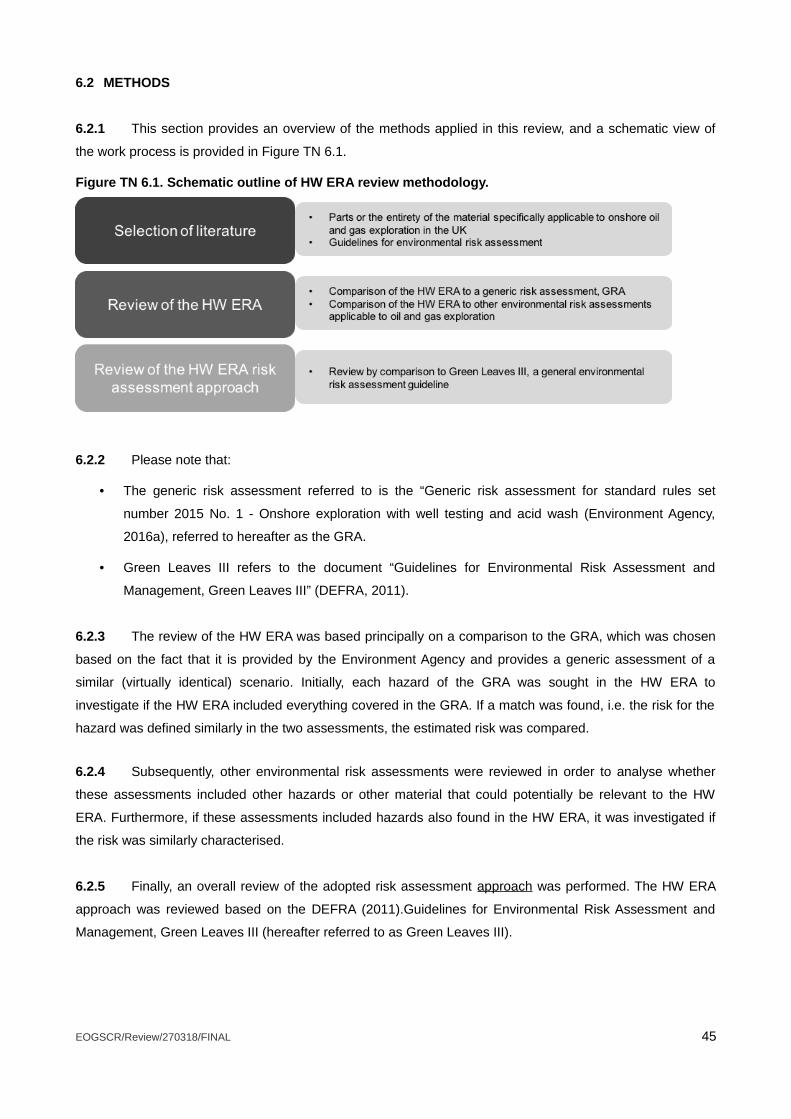
6.2 METHODS
6.2.1 This section provides an overview of the methods applied in this review, and a schematic view of
the work process is provided in Figure TN 6.1.
Figure TN 6.1. Schematic outline of HW ERA review methodology.
6.2.2 Please note that:
• The generic risk assessment referred to is the “Generic risk assessment for standard rules set
number 2015 No. 1 - Onshore exploration with well testing and acid wash (Environment Agency,
2016a), referred to hereafter as the GRA.
• Green Leaves III refers to the document “Guidelines for Environmental Risk Assessment and
Management, Green Leaves III” (DEFRA, 2011).
6.2.3 The review of the HW ERA was based principally on a comparison to the GRA, which was chosen
based on the fact that it is provided by the Environment Agency and provides a generic assessment of a
similar (virtually identical) scenario. Initially, each hazard of the GRA was sought in the HW ERA to
investigate if the HW ERA included everything covered in the GRA. If a match was found, i.e. the risk for the
hazard was defined similarly in the two assessments, the estimated risk was compared.
6.2.4 Subsequently, other environmental risk assessments were reviewed in order to analyse whether
these assessments included other hazards or other material that could potentially be relevant to the HW
ERA. Furthermore, if these assessments included hazards also found in the HW ERA, it was investigated if
the risk was similarly characterised.
6.2.5 Finally, an overall review of the adopted risk assessment approach was performed. The HW ERA
approach was reviewed based on the DEFRA (2011).Guidelines for Environmental Risk Assessment and
Management, Green Leaves III (hereafter referred to as Green Leaves III).
EOGSCR/Review/270318/FINAL 45
6.3 LITERATURE REVIEW
6.3.1 The following constitutes a summary of the findings of the literature review. The complete literature
review is provided in Appendix TN1.
6.3.2 The literature was chosen based on the criterion that it should be applicable to onshore oil and gas
exploration in the EU and the UK. The material chosen is applicable in its entirety or by parts of the project or
subject studied.
6.3.3 In particular, it is important to note that the literature identifies that shale gas exploration operations
have a significant overlap with conventional methods by, for example, site preparations, well construction
and integrity, handling, storage and transportation of hazardous material and well decommissioning (Amec
Foster Wheeler Environment and Infrastructure UK Ltd, 2016; Environment Agency, 2013).
6.3.4 Some of the literature reviewed is developed by, or for, the UK government and constitutes the
basis for reviewing the risk assessment contents and approach of the HW ERA. Other literature is added in
an attempt to broaden the comparison and raise other views possibly not present in the former material. This
study has focused predominantly on general guidelines or risk assessments.
6.3.5 The material can be divided into three groups as summarised below. A brief description of the
contents of each of these documents is provided in Appendix TN1:
1. General risk assessments on onshore oil and gas exploratory activities and shale gas exploratory
operations in the UK and Europe. This material includes the following primary documents:
Amec Foster Wheeler Environment and Infrastructure UK Ltd (2016). Study on the assessment
and management of environmental impacts and risks resulting from the exploration and production
of hydrocarbons. ISBN 978-92-79-62747-7.
Environment Agency (2010a). Review of assessment procedures for shale gas well casing
installation. LIT 7311.
Environment Agency (2010b, 2016a). Standard rules SR2015. No 1. The management of
extractive waste, not including a waste facility, generated from onshore oil and gas prospecting
activities including drilling, coring, leak off testing (LOT), acid wash and decommissioning but
excluding hydraulic fracturing for the production of oil or gas (using oil and water based drilling mud).
LIT 10411 and LIT 10412.
Environment Agency (2013). An Environmental Risk Assessment for shale gas exploratory
operations in England. Version 1. LIT 8474.
EOGSCR/Review/270318/FINAL 46
2. Other relevant guidelines, regulations and governmentally produced material:
Department of Energy and Climate Change (2013). Onshore oil and gas exploration in the UK:
regulation and best practice.
DEFRA (2011) Guidelines for Environmental Risk Assessment and Management, Green Leaves III.
Environment Agency (2016b) Onshore oil and gas sector guidance. Version 1. LIT 10495.
3. Other literature on risk management and environmental impact:
• Clancy, S.A. and Worrall, D. (2016) Review of spills and leaks from normal shale gas
operations. M4ShaleGas Report deliverable number D12.2
• Cuadrilla Bowlamd Ltd and ARUP (2014) Temporary shale gas exploration Preston New Road,
Lancashire. Environmental risk assessment.
• Det Norske Veritas AS, DNV. (2013) Risk management of shale gas development and operations.
DNV-RP-U301.
• Liu, W., Ramirez, A. (2017) State of the art review of the environmental assessment and risks of
underground geo-energy resources exploitation. Renewable and Sustainable Energy Reviews.
• ter Heeg, J. (2017b) Subsurface risks and impacts of shale gas operations. M4ShaleGas Report
deliverable number D6.2
• United States Environmental Protection Agency (USEPA) (2016) Hydraulic fracturing for oil and
gas: Impacts from the hydraulic fracturing water cycle on drinking water resources in the United
States. EPA-600-R-16-236Fa.
• Vengosh, A., Jackson, R.B., Warner, N., Darrah, T.T and Kondash, A. (2014) A critical review of
the risks to water resources from unconventional shale gas development and hydraulic fracturing in
the United States. (2014). Environmental Science and Technology, (48): 8334-8348.
• Worrall, F., Clancy, S.A., Goodman, P., Thorpe, N. and Willis, S. (2017a) Final report on impact of
well site infrastructure and transport. M4ShaleGas Report deliverable number: D12.6.
EOGSCR/Review/270318/FINAL 47
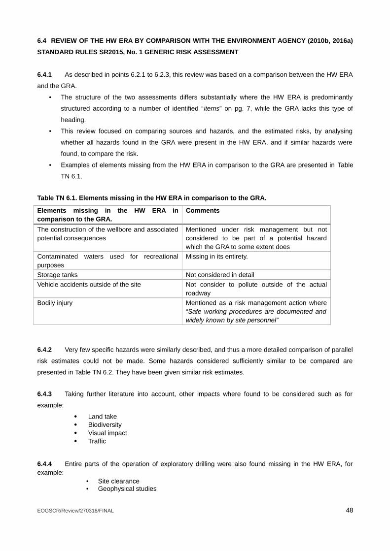
6.4 REVIEW OF THE HW ERA BY COMPARISON WITH THE ENVIRONMENT AGENCY (2010b, 2016a)
STANDARD RULES SR2015, No. 1 GENERIC RISK ASSESSMENT
6.4.1 As described in points 6.2.1 to 6.2.3, this review was based on a comparison between the HW ERA
and the GRA.
• The structure of the two assessments differs substantially where the HW ERA is predominantly
structured according to a number of identified “items” on pg. 7, while the GRA lacks this type of
heading.
• This review focused on comparing sources and hazards, and the estimated risks, by analysing
whether all hazards found in the GRA were present in the HW ERA, and if similar hazards were
found, to compare the risk.
• Examples of elements missing from the HW ERA in comparison to the GRA are presented in Table
TN 6.1.
Table TN 6.1. Elements missing in the HW ERA in comparison to the GRA.
Elements missing in the HW ERA incomparison to the GRA.
Comments
The construction of the wellbore and associatedpotential consequences
Mentioned under risk management but notconsidered to be part of a potential hazardwhich the GRA to some extent does
Contaminated waters used for recreationalpurposes
Missing in its entirety.
Storage tanks Not considered in detail
Vehicle accidents outside of the site Not consider to pollute outside of the actualroadway
Bodily injury Mentioned as a risk management action where“Safe working procedures are documented andwidely known by site personnel”
6.4.2 Very few specific hazards were similarly described, and thus a more detailed comparison of parallel
risk estimates could not be made. Some hazards considered sufficiently similar to be compared are
presented in Table TN 6.2. They have been given similar risk estimates.
6.4.3 Taking further literature into account, other impacts where found to be considered such as for
example:
Land take Biodiversity Visual impact Traffic
6.4.4 Entire parts of the operation of exploratory drilling were also found missing in the HW ERA, forexample:
• Site clearance• Geophysical studies
EOGSCR/Review/270318/FINAL 48

• Baseline monitoring• Well pad construction• Rig installation• Well stabilisation• Site restoration• Long term well integrity and impact monitoring
Table TN 6.2. Hazards similarly described in the HW ERA and the GRA with compared risk estimate.
Heading in the HW ERA
Hazard in the HW ERA
Estimated risk HW ERA
Estimated riskGRA (comparablehazard)
Assessment ofpossible source ofaccidents
Fires or failure to containfire water, Pg. 26.
“Low if managementtechniques, planningand procedures arefollowed”, comparablehazards in the GRAwere given the risk“Low”.
“Low”
Vandalism, Pg. 29 “Low if managementtechniques, planningand procedures arefollowed”, comparablehazards in the GRAwere given the risk“Low”.
“Low”
Discharges tosurface waterassessment
Overflow of site perimeterditches. Pg. 32.
“Insignificant” “Very low”
6.4.5 Besides these categories of individual elements or parts of site construction/infrastructure
management, other specific hazards or events are related to operational risks, for example, potential
blowouts if encountering gas, explosions and fire risk.
6.4.6 The HW ERA also fails to mention the probability of inaccurate pre-investigations, miscalculations
or drilling errors leading to not encountering the sought formation.
6.4.7 The risks in the HW ERA are all ultimately characterised as “Low”, “Insignificant” or “None”,
sometimes with variations of the comment that the estimation is valid if “management techniques, planning
and procedures are followed”. The GRA finds one hazard to still be “Medium” after risk management.
However, the ‘Study on the assessment and management of environmental impacts and risks resulting from
the exploration and production of hydrocarbons’ (Amec Foster Wheeler, 2016), which presents a thorough
environmental risk assessment, finds a number of processes/technologies that pose a moderate, high or
even very high risk after management. A few examples are presented in Table TN 6.3.
EOGSCR/Review/270318/FINAL 49
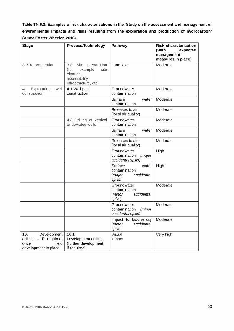
Table TN 6.3. Examples of risk characterisations in the ‘Study on the assessment and management of
environmental impacts and risks resulting from the exploration and production of hydrocarbon’
(Amec Foster Wheeler, 2016).
Stage Process/Technology Pathway Risk characterisation(With expectedmanagementmeasures in place)
3. Site preparation 3.3 Site preparation(for example siteclearing,accessibility,infrastructure, etc.)
Land take Moderate
4. Exploration wellconstruction
4.1 Well padconstruction
Groundwatercontamination
Moderate
Surface watercontamination
Moderate
Releases to air(local air quality)
Moderate
4.3 Drilling of verticalor deviated wells
Groundwatercontamination
Moderate
Surface watercontamination
Moderate
Releases to air (local air quality)
Moderate
Groundwatercontamination (majoraccidental spills)
High
Surface watercontamination (major accidentalspills)
High
Groundwater contamination (minor accidentalspills)
Moderate
Groundwatercontamination (minoraccidental spills)
Moderate
Impact to biodiversity(minor accidentalspills)
Moderate
10. Developmentdrilling – if required,once fielddevelopment in place
10.1Development drilling(further development,if required)
Visualimpact
Very high
EOGSCR/Review/270318/FINAL 50
6.5 A REVIEW OF THE OVERARCHING RISK ASSESSMENT APPROACH APPLIED IN THE HW ERA
6.5.1 A review of the risk assessment approach itself was performed supported by Green Leaves III
(DEFRA, 2011), which are guidelines provided by DEFRA and used elsewhere in the application material,
notably the hydrogeological risk assessment. The following comments are structured after the headings in
the HW ERA.
6.5.2 Section 2, Scope, Pg. 5. The HW ERA includes a short scope. It is stated that “all exploratory
operations” are considered. Yet, there is little to no consideration of pre-investigatory operations or
decommissioning within the HW ERA.
6.5.3 A number of useful delimitations to the risk assessment are not stated, for example:
• The geographical scale of the operations could not be ascertained from the HW ERA
• The time scale covered by the assessment could not be ascertained from the HW ERA
• Whether or not risks to personnel on site are considered.
• It could also be further clarified what elements of the HW ERA are covered in more detail in the
hydrogeological risk assessment.
6.5.4 Section 3, Definitions, Pg. 6. “Overall risk” is defined as “A hazard that has been assessed and
has been given a risk rating level post mitigation measures i.e. not significant, low, medium, high very high
etc.” while it seems that in the actual assessment, the risk estimate is based on a combination of
consequence and probability of exposure.
6.5.5 Pg. 6. The levels of severity of risk are only vaguely described.
6.5.6 Section 4, Methodology, Pg. 7. It is stated that the structure of the assessment is consistent with
guidance from the Environment Agency but there is no reference provided. The Environment Agency and
DEFRA provides a website where information on risk assessments is gathered2, and DEFRA also provides
the Green Leaves III (DEFRA, 2011) giving an overall guidance on risk assessment, described further in
Appendix TN1.
6.5.7 Green Leaves III stresses the importance of formulating the problem for effective risk management
along with how formulation of the problem can facilitate the selection of methods within the assessment and
improve the risk management decision. Four steps are mentioned in the process of formulating the problem:
Framing the question Developing a conceptual model Planning the assessment and, Prioritising risks to be assessed.
2 DEFRA and Environment Agency, UK. Guidance Risk assessments for your environmental permit. When you need to do an environmental risk assessment, when the Environment Agency will do it for you, and how to do a risk assessment. https://www.gov.uk/guidance/risk-assessments-for-your-environmental-permit#how-to-do-a-risk-assessment accessed 16/3/18
EOGSCR/Review/270318/FINAL 51
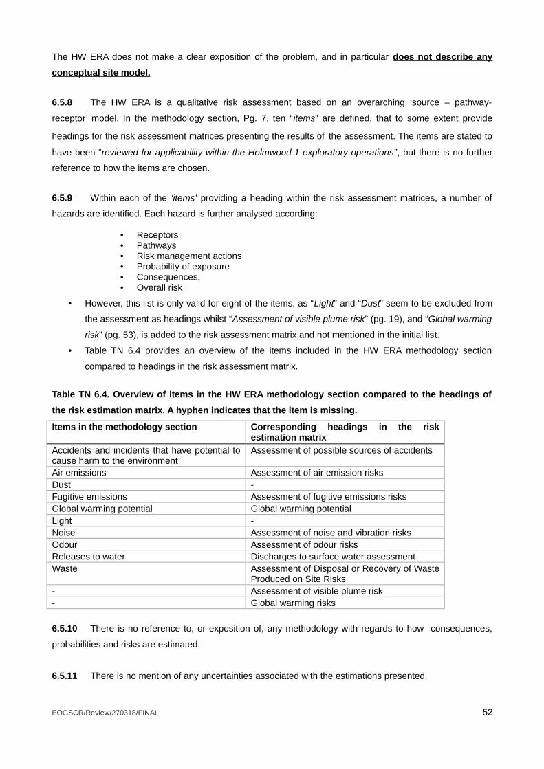
The HW ERA does not make a clear exposition of the problem, and in particular does not describe any
conceptual site model.
6.5.8 The HW ERA is a qualitative risk assessment based on an overarching ‘source – pathway-
receptor’ model. In the methodology section, Pg. 7, ten “items” are defined, that to some extent provide
headings for the risk assessment matrices presenting the results of the assessment. The items are stated to
have been “reviewed for applicability within the Holmwood-1 exploratory operations”, but there is no further
reference to how the items are chosen.
6.5.9 Within each of the ‘items’ providing a heading within the risk assessment matrices, a number of
hazards are identified. Each hazard is further analysed according:
• Receptors• Pathways• Risk management actions• Probability of exposure• Consequences,• Overall risk
• However, this list is only valid for eight of the items, as “Light” and “Dust” seem to be excluded from
the assessment as headings whilst “Assessment of visible plume risk” (pg. 19), and “Global warming
risk” (pg. 53), is added to the risk assessment matrix and not mentioned in the initial list.
• Table TN 6.4 provides an overview of the items included in the HW ERA methodology section
compared to headings in the risk assessment matrix.
Table TN 6.4. Overview of items in the HW ERA methodology section compared to the headings of
the risk estimation matrix. A hyphen indicates that the item is missing.
Items in the methodology section Corresponding headings in the riskestimation matrix
Accidents and incidents that have potential tocause harm to the environment
Assessment of possible sources of accidents
Air emissions Assessment of air emission risksDust -Fugitive emissions Assessment of fugitive emissions risksGlobal warming potential Global warming potentialLight -Noise Assessment of noise and vibration risksOdour Assessment of odour risksReleases to water Discharges to surface water assessmentWaste Assessment of Disposal or Recovery of Waste
Produced on Site Risks- Assessment of visible plume risk- Global warming risks
6.5.10 There is no reference to, or exposition of, any methodology with regards to how consequences,
probabilities and risks are estimated.
6.5.11 There is no mention of any uncertainties associated with the estimations presented.
EOGSCR/Review/270318/FINAL 52
6.5.12 Risk is estimated for all receptors relevant for the hazard in a single estimate as opposed to each
receptor. Thus, for example, the probability of transfer of pollutants by potentially different pathways is not
distinguished.
6.5.13 It is not discussed what is considered an acceptable risk and when the risk is so extensive that
mitigation measures are needed.
6.5.14 ‘Appraising the options’ and ‘addressing the risk, being the last two steps of the risk assessment
and management process according to the Green Leaves III (DEFRA, 2011), are touched upon in the risk
assessment matrix presented in the HW ERA in the “Risk management” – column, pg. 11 to 53, but there is,
for example, no estimate on what the risk was prior to implementation of management options, or how those
options were selected.
6.5.15 The descriptions of ‘Probability of Exposure’ given in the risk assessment matrices are frequently
descriptions not of probability, but of either a Hazard, a Pathway, or a Risk Management procedure.
• Of the many examples to choose from, a representative situation is given under ‘Assessment of
Possible Source of Accidents’ on pg. 21, where the probability of exposure is described as
’Unchecked, ditches could overflow (a hazard) and run-off could reach localised receptors (a
pathway) but management actions should prevent this from happening. (management actions)’. (with
parentheses and underlining by the authors of this Technical Note).
• In other words, probabilities of exposure have been widely mistaken for other elements of the risk
assessment.
• Assessment of the probability of occurrence of the identified hazards is completely absent in a large
number of instances.
6.5.16 There is no summary.
6.5.17 There is no discussion.
6.5.18 There are no conclusions.
6.5.19 There is no list of references.
6.5.20 The above series of omissions must, taken together, constitute a serious failing of the stated
intentions to assess risk in a meaningful way.
EOGSCR/Review/270318/FINAL 53
6.6 DISCUSSION REGARDING HW ERA
6.6.1 The purpose of this work was to review the HW ERA with respect to the current state of knowledge.
A review of relevant literature was performed in order to investigate if there were hazards or parts of other
risk assessments not included in the HW ERA. Moreover, if similar hazards to those identified in the HW ERA
were found, compare the risk characterization. A review of the overall risk assessment approach applied in
the HW ERA has also been performed.
6.6.2 Other risk assessments for similar purposes identify, for example, the construction of the wellbore
and abandonment and decommissioning as actions potentially posing a risk, and these are just a few
examples of actions or processes to a large extent missing in the HW ERA.
6.6.3 This review has not attempted an exhaustive list of potentially missing parts of the HW ERA, mainly
because the unclear scope and lack of conceptual model does not provide a sufficient framework and
delimitations for compiling such list. It is however shown that the HW ERA has failed to include significant
parts of the exploratory operation that is considered in other literature.
6.6.4 A comparison of absolute risk characterisations was made, but since only a few hazards were
found sufficiently similar between the HW ERA and the GRA, it does not give viable input to a general
discussion on plausibility of the risk levels estimated in the HW ERA.
6.6.5 However, overall it was found that the HW ERA does not characterise any risk to be greater than
low after mitigation measures, while the ‘Study on the assessment and management of environmental
impacts and risks resulting from the exploration and production of hydrocarbons’ (Amec Foster Wheeler,
2016) characterises a number of risks above moderate. For example, “Drilling of vertical or deviated wells” is
found to potentially pose a moderate and high risk to groundwater, surface water and biodiversity.
6.6.6 The HW ERA characterises many risks as “Low if management techniques, planning and
procedures are followed” but does not elaborate such procedures or discuss potential problems with the
mentioned mitigation measures.
6.6.7 A number of European Union Horizon 2020 funded projects have focussed on risks associated with
unconventional hydrocarbon exploration and development, drawing upon analogues with conventional oil
and gas operations (please see Appendix TN1 to this Technical Note).
• It is widely stated throughout these studies that significant levels of uncertainty are still currently
associated with particular risks, including, for example, water pollution due to inappropriate well
casing, waste management or insufficient ground characterisation.
• For example, the Science for Clean Energy (S4CE) research project (with ~10 million euros funding,
and which commenced in January 2018) “aims to develop, test and implement technologies needed
for successfully detecting, quantifying and mitigating the risks connected with geo-energy operations
EOGSCR/Review/270318/FINAL 54
in the sub-surface” and one of the specific objectives is to overcome knowledge gaps within “the
detection of failure of concrete casings, the quantification, prediction and eventual control of fluid
transport pathways in sub-surface rock formations and cement-based materials”3
• The HW ERA does not discuss any such uncertainties specific to the Holmwood wellsite explorations
and nor in regard to these more general issues.
• There is no attempt to identify or utilise available up-to-date literature to inform or characterise risks
on site, even in a qualitative manner, despite its availability.
6.6.8 The review of the risk assessment approach applied in the HW ERA revealed a number of potential
issues including a scope expressed in very general, rudimentary terms and especially lack of a conceptual
model.
6.6.9 A more detailed definition of the levels of severity of probabilities, consequences and risk would
facilitate a comparison to other risk assessments on exploratory operations and provide transparency to the
assessment.
6.6.10 Fundamentally, no conceptual model is presented. Potential parts of such can be found in for
example the Holmwood site plans exploratory operations (Europa Oil and Gas Limited, 2017c) where a plan
of the site can be found or in the Waste Management Plan, or the Site Condition Report (Europa Oil and Gas
Limited, 2017a and 2017c) where descriptions of the drilling pad can be found. Those descriptions are,
however, not utilised for creating a comprehensive conceptual model. A conceptual model could also have
facilitated deriving the “items” and further on in the risk assessment, a thorough hazard identification, but this
is not achieved.
6.6.11 Several parts of the risk assessment lack a methodological description with regards to, for
example, hazard identification or risk characterization. Even if the risk assessment for the HW ERA is, and
should be, site-specific, these are issues that might contribute to the fact that some hazards or parts of
processes were found missing in the HW ERA.
6.6.12 A more detailed table of contents would have facilitated reading and understanding the 54 pages
long HW ERA.
6.6.13 A summary, conclusion and/or discussion would further have aided the reader. It could provide the
reader with overview of, for example, the hazards posing the largest risk or what mitigation actions are going
to be taken.
6.6.14 Clearly stated references would further have increased the credibility of the HW ERA and facilitated
scrutiny.
3 http://science4cleanenergy.eu/about
EOGSCR/Review/270318/FINAL 55
6.7 CONCLUSIONS REGARDING HW ERA
6.7.1 The purpose of this work was to review the HW ERA with respect to the current state of knowledge.
A review of relevant literature was performed in order to investigate if there were hazards or parts of other
risk assessments not included in the HW ERA. Moreover, if similar hazards to those identified in the HW ERA
were found, compare the risk characterization. A review of the overall risk assessment approach applied in
the HW ERA has also been performed.
6.7.2 In comparison to similar risk assessments, parts of the exploration process and potential hazards
are found not to be present in the HW ERA.
6.7.3 A generic European risk assessment for the exploration and production of hydrocarbons find
several risks characterised as moderate or greater while the HW ERA identifies all risks as “Low”,
“Insignificant” or “None” after mitigation measures.
6.7.4 The findings of the review of the risk assessment approach applied in the HW ERA reveals that
there is great room for improvement regarding the statement of the scope and that there is a general lack of
structure, method description and uncertainty analysis. Furthermore, no conceptual model is developed.
6.7.5 The lack of discussions, references, methodological descriptions, conceptual model, assessments
of probability of occurrence etc. all contribute toward significantly undermining the credibility of the risk
assessment.
6.7.6 Whilst the Environment Agency state in the draft permit decision that “the operator´s risk
assessment is satisfactory” (Environment Agency, 2018), they may benefit from the additional considerations
of the numerous issues that remain unresolved in the HW ERA, which have been identified within this review,
and which strongly indicate the HW ERA to be of an unacceptable standard.
EOGSCR/Review/270318/FINAL 56

7.0 SUMMARY AND CONCLUSIONS
7.1 This Technical Note presents a review of documents submitted by Europa Oil and Gas Ltd in
support of an application to undertake onshore oil and gas exploratory operations at ‘Holmwood Wellsite,
Bury Hill Wood, Coldharbour Lane, Surrey, RH5 6HN’. The Environmental Permit Application number is
EPR/YP3735YK/A001.
7.2 The primary document reviewed was the ‘Site Condition Report’ (SCR, document no. EOG-EPRA-
HW-SCR-006). The SCR contains a number of appendices, of which, in particular, the ‘Hydrogeological risk
assessment and conceptual model’ (Appendix 3), the ‘Groundwater monitoring strategy’ (Appendix 2), and
the ‘WR11 Application’ (Appendix 4) are reviewed in detail in this Technical Note. The separate application
document ‘Holmwood Wellsite Environmental Risk Assessment’ (document no. EOG-EPRA-HW-ERA-007) is
also reviewed.
7.3 Many significant errors, inconsistencies and omissions have been identified throughout the
documents reviewed. These are detailed throughout this Technical Note and the major criticisms are outlined
in this summary.
7.4 However, due to time constraints, it has not been possible to ribustly review additional documents,
notably the site Waste Management Plan (document no. EOG-EPRA-HW-WMP-005).
7.5 It is noted that the one-month consultation is a wholly inadequate time period in which to robustly
review and form views on several hundred pages of technical material. Consequently, the Regulator’s role is
frustrated, as there is insufficient opportunity for an alternative technical viewpoint to be presented and as
such limits the capacity of the Environment Agency to make a fully informed objective assessment.
7.6 It is hoped that the technical review presented here will be of some assistance to the Regulator in
providing additional detailed technical information informing their objective assessment of the application.
7.7 Review summary: SITE CONDITION REPORT
7.7.1 The Site Condition Report (Revision no. 4) document, including Appendices, runs to 307
pages.
7.7.2 Much of the material presented in the SCR (Rev. 4) document is repetitious, and the exact
same text is cut-and-paste between various sections; however, is attributed to different authors. This has
resulted in a lack of transparency regarding who, specifically, has authored these repetitious sections.
EOGSCR/Review/270318/FINAL 57
7.7.3 For instance, Figure 5a ‘Well Construction Concept’ appears throughout the document no
fewer than 7 times, in what appears to be at least two different formats. This particular figure is authored by
Envireau Water Ltd, but various other sections of ambiguous authorship are identified.
7.7.4 The degree of repetition needlessly lengthens, and significantly confuses, the entire SCR (rev.
4) document. Overall, the document demonstrates:
• Lack of accurate pagination.
• Lack of an accurate Table of Contents.
• Frequent lack of consistency.
• Needless and excessive repetition.
7.7.5 Altogether these failings demonstrate a lack of basic presentational skills and serve to
obfuscate the material and make it less tractable to analysis. This presents a major problem in terms of
presenting the SCR (Rev. 4) document as part of a public consultation, because, for the reasons given, it is
not suitable for this purpose.
7.7.6 It is also questionable that the standard of the submission meets the Environment Agency’s
expectations for such applications and associated supporting information.
7.7.7 The SCR (Rev. 4) document states that “The purpose of this document is to document the
condition of the proposed site prior to and in support of an environmental permit being submitted to the
Environment Agency.” Further, the Environment Agency (2016) Onshore Oil and Gas Sector Guidance
defines a Site Condition Report as follows: “You will need to carry out some monitoring before starting your
operations, so that a baseline can be established. This is called a site condition report (SCR).”
7.7.8 Throughout the 307 pages of the SCR (Rev. 4) document, quantitative measurements of the
environmental conditions at and around the site are not presented. Therefore, the SCR (Rev. 4) document
cannot be considered more than a desk-top study of published information. Thus, it does not form a record of
the site condition in the sense implied by the Environment Agency guidance and is considered demonstrably
inadequate for the purposes that it set out to achieve.
7.7.9 Several different and inconsistent statements regarding site area and surface covering
materials are made throughout the SCR (Rev. 4) document and elsewhere in the application. Due to these
inconsistencies it is not possible to have sufficient confidence in the water management calculations
presented.
7.7.10 The final site design does not appear to have been presented.
7.7.11 Neither the geological memoir for the area, nor the latest geological mapping, appear to inform
the site condition report.
EOGSCR/Review/270318/FINAL 58
7.7.12 Several significant omissions or failures to present or adequately interpret existing geological
data are noted with regards site characterisation. For example, the azimuth of the dip of the Hythe Beds
principal aquifer are demonstrably different to those presented within the SCR (shown to be NNE, not NW
as stated by the Applicant). There are further significant omissions relating to lithology and geological
structure.
7.7.13 Quaternary deposits are noted on the latest 1:10,000 geological mapping with a significantly
different distribution to the Quaternary deposits as noted on the 1:50,000 geological maps used as the base
maps for the hydrogeological risk assessment. These need to be considered as they alter the picture of a
lack of hydrogeological continuity between the Hythe Beds at the site with the Lower Greensand used for the
Dorking water supply.
7.7.14 These failings of geological understanding have important implications for the subsequent
hydrogeological conceptualisation and risk assessment.
7.7.15 Terminology regarding containment systems for pollution prevention is muddled.
7.7.16 Risk assessment methodologies for the selection of appropriate design criteria for containment
systems for pollution prevention are not presented.
7.7.17 Common design standards for containment systems for pollution prevention are not
incorporated into site design. This is considered an unacceptable failure of site design for the proposed
facility.
7.8 Review summary: HYDROGEOLOGICAL RISK ASSESSMENT (Appendix 3 to the SCR)
7.8.1 The proposed site is situated on a Principal Aquifer, the Lower Greensand (in particular, the
Hythe Formation). However, discussion of the mode of groundwater flow in the aquifer is extremely limited.
There is no discussion of the following basic hydrogeological parameters:
porosity (total and effective)
hydraulic conductivity
transmissivity
storage
recharge
hydraulic gradient
groundwater velocity
seasonal variations in groundwater level
seasonal variation in groundwater divides and groundwater catchment boundaries
likely groundwater quality
EOGSCR/Review/270318/FINAL 59
heterogeneity
anisotropy
7.8.2 There is no reference to the regional groundwater models for the Lower Greensand aquifer or
the Mole catchment, nor to the conceptual models used to inform and underpin these works. Therefore, due
consideration of the data available to the Environment Agency (and general public) has not been brought into
the Applicant’s supporting information.
7.8.3 The report also fails to discuss relevant contaminant transport parameters, physical and
geochemical mechanisms within the Hythe Beds, structural influences such as folding, faulting or cambering,
aquifer mineralogy and geochemistry, or any kind of water balance or mass balance.
7.8.4 For example, fracture vs. fissure flow is clearly relevant to potential contaminant transport and
hence to risk assessment. It has been pointed out that faults exist in close proximity to the site and
elsewhere within the Lower Greensand outlier within which the site is situated. However, none of this
information is translated into or informs the hydrogeological conceptualisation as presented.
7.8.5 Without presentation or discussion of the above listed parameters and concepts it is not
possible to formulate a robust conceptualisation on which to base and qualify a site-specific risk assessment.
Furthermore, the design of the monitoring programme and the development of the risk assessment are built
on the robustness of the conceptual understanding. A poorly constructed and poorly substantiated
conceptual model leads to poor monitoring design and limits interpretation of data.
7.8.6 Overall, the absence of the presentation of a sound hydrogeological conceptual understanding
in the supporting information results in inadequacies in monitoring design, risk assessment and risk
mitigation.
7.8.7 The justification for adopting a qualitative risk assessment is that there are few or only
insignificant uncertainties in our state of knowledge regarding the hydrogeology. However, there is no
acknowledgement of any uncertainties or possible lack of information. The words ‘uncertainty’ or
‘uncertainties’ do not appear at any point in Appendix 3.
7.8.8 No risk screening exercise is either conducted or discussed to determine the appropriateness
of the level of risk assessment adopted. Nor are any basic scoping calculations supporting qualitative
assessment made.
7.8.9 These omissions are in direct contrast to recommendations made in both the DEFRA (2011)
Greenleaves III and the Environment Agency’s H1 Environmental Risk Assessment framework – Annex J
(Groundwater) documents, which are stated as being the guiding principles by which the risk assessment is
conducted.
EOGSCR/Review/270318/FINAL 60
7.8.10 On these grounds the appropriate level of risk assessment to address outstanding
uncertainties has not been identified (or even discussed). The resultant arbitrary selection of the simplest
(i.e. qualitative) risk assessment method remains unsubstantiated.
7.8.11 This coupled with the failure to present basic hydrogeological information and hence a failure
to describe the groundwater system in anything other than the most rudimentary detail, mean that the risk
assessment is not fit for purpose.
7.8.12 Many other more detailed criticisms of the presented hydrogeological conceptualisation are
presented in this Technical Note.
7.9 Review summary: GROUNDWATER MONITORING STRATEGY (Appendix 2 to the SCR)
7.9.1 Aside from criticisms regarding failure of the hydrogeological conceptualisation to inform
monitoring as summarised above, specific criticisms of the proposed monitoring strategy include:
7.9.2 Unsubstantiated dismissal of monitoring of certain potential contaminant receptors.
7.9.3 Inconsistent statements concerning the outcome of the risk assessment with regards potential
receptors.
7.9.4 Failure to account for the potential influence of faults and fracturing on groundwater flow.
7.9.5 Failure to include additives proposed for use during the drilling and testing operations within
the testing schedule, despite these presented as already understood and declared within the application.
7.9.6 The proposed period of baseline monitoring (3 months) is inconsistent with establishing a
natural baseline, for which at a minimum one hydrological year’s worth of data are required.
7.9.7 This proposed period of baseline monitoring is also inconsistent with other areas of regulated
consented activities by the Environment Agency. For example, where a groundwater abstraction licence may
have the potential for significant adverse impact, the Environment Agency may expect a more extensive
period of monitoring and assessment in terms of impact on the aquatic environment aligned with the
requirements of the Water Framework Directive. As the proposed development has the potential for
significant adverse impact, it is reasonable to expect a minimum of a period of one year of baseline
monitoring to support this application, with the minimum of one year monitoring period to include the annual
hydrograph.
EOGSCR/Review/270318/FINAL 61
7.9.8 It is noted that over a decade has elapsed since the origin of this application. Such a total failure to
obtain any baseline information whatsoever during this period appears to illustrate a considerable lack of
foresight, further undermining confidence in the Applicant’s ability to accurately assess the associated risks.
7.10 Review summary: WR11 APPLICATION (Appendix 4 to the SCR)
7.10.1 The wellsite appears to be located in a significantly sub-optimal location with regards the
target formations to be drilled.
◦ A large part of the WR11 appendix is devoted to justifying the use of oil-based drilling muds at a
much shallower depth (177 m TVD-GL) than previously imagined for the site (460 m TVD-GL).
◦ This is because numerous reinterpretations of seismic and other data have necessitated
adoption of a technically extreme (i.e. at the very limit of what is technically possible) and “highly
unusual” drilling angle ‘without any scope for relaxation’ should ground conditions prove to be
other than anticipated.
◦ The location of the drill site therefore introduces additional risk, establishes the drilling method at
its limits and increases the risk of borehole construction and integrity failures.
7.10.2 No data are presented regarding the mechanical properties of the formations targeted for acid
squeeze.
◦ It is therefore impossible to ascertain from the material presented whether any consideration has
been given to the exceedance of fracture pressure of those formations using the proposed
technique.
◦ Without an assessment of the mechanical properties of the target formation, it is not viable to
confidently determine the pressure at which the target formation is likely to fracture. Therefore,
the “fracture pressure of the formation” is unknown for the target formations at their respective
depths, resulting in insufficient confidence and inadequate assessment of the limits of the acid
squeeze method that avoid pressures that could result in hydraulic fracturing.
◦ The approach proposed to test the pressure in the field does not provide sufficient confidence
that the acid squeeze will not result in hydraulic fracturing; and the method inadequately
assesses and mitigates the risk of hydraulic fracturing taking place within the bespoke permit for
exploratory operations.
7.10.3 Admission that the proposed well is designed for production:
◦ Section 7, Well Abandonment and Partial Well Abandonment, pg. 169. “In the event that the
borehole is not successful in establishing commercially producible petroleum, the
borehole will be abandoned...”
◦ This statement confirms that the exploratory well is intended for production should the resource
prove commercially viable. This is, therefore, contrary to much of the emphasis of the risk
assessment, and various aspects of the site design, which stress the temporary nature of the
wellsite due to its exploratory nature.
EOGSCR/Review/270318/FINAL 62
◦ It therefore appears that the hydrogeological risk assessment (and presumably other aspects)
were undertaken without due regard for the activities proposed on site.
◦ The stated intention contradicts the intention of the draft bespoke permit as issued by the
Environment Agency which establishes exploratory operation and testing rather than a
commercially productive petroleum borehole.
◦ Measures to ensure that the exploration borehole is not used for the Applicant’s stated purpose
must be clearly stated by the Environment Agency; with measures in place for the Applicant and
Regulator to demonstrate compliance with the permit requirements throughout each stage of
exploration. Such measures are not clearly stated by the Applicant in their supporting
information or the Regulator in the draft bespoke permit document.
7.11 Review summary: ENVIRONMENTAL RISK ASSESSMENT (HW ERA, document no. EOG-
EPRA-HW-ERA-007)
7.11.1 The purpose of this work was to review the HW ERA with respect to the current state of
knowledge. A review of relevant literature was performed in order to investigate if there were hazards or parts
of other risk assessments not included in the HW ERA. Moreover, if similar hazards to those identified in the
HW ERA were found, compare the risk characterization. A review of the overall risk assessment approach
applied in the HW ERA has also been performed.
7.11.2 In comparison to similar risk assessments, and in particular the Environment Agency (2010b,
2016a) Standard Rules SR2015 (No. 1) Generic Risk Assessment for onshore oil and gas installations, parts
of the exploration process and potential hazards are found not to be present in the HW ERA.
7.11.3 A generic European risk assessment for the exploration and production of hydrocarbons found
several risks characterised as moderate or greater while the HW ERA identifies all risks as “Low”,
“Insignificant” or “None” after mitigation measures.
7.11.4 The findings of the review of the risk assessment approach applied in the HW ERA reveals
that there is great room for improvement regarding the statement of the scope and that there is a general
lack of structure, method description and uncertainty analysis. Furthermore, no conceptual model is
developed.
7.11.5 The lack of discussions, references, methodological descriptions, conceptual model,
assessments of probability of occurrence etc. all contribute toward significantly undermining the credibility of
the risk assessment.
EOGSCR/Review/270318/FINAL 63

7.11.5 Whilst the Environment Agency state in the draft permit decision that “ the operator´s risk
assessment is satisfactory” (Environment Agency, 2018), they may benefit from the additional considerations
of the numerous issues that remain unresolved in the HW ERA, which have been identified within this review,
and which strongly indicate the HW ERA to be of an unacceptable standard.
EOGSCR/Review/270318/FINAL 64
8.0 References
Allen, D. J., Brewerton, L. J., Coleby, L. M., Gibbs, B. R., Lewis, M. A., MacDonald, A. M., Wagstaff, S.
J. and Williams, A T. (1997) The physical properties of major aquifers in England and Wales. British
Geological Survey Technical Report WD/97/34. 312pp. Environment Agency R&D Publication 8.
Amec Foster Wheeler Environment and Infrastructure UK Ltd (2016) Study on the assessment and
management of environmental impacts and risks resulting from the exploration and production of
hydrocarbons. ISBN 978-92-79-62747-7.
British Geological Survey (2001) Guildford. England and Wales sheet 285. Solid and Drift Geology
1:50,000 (Keyworth, Nottingham, British Geological Survey)
CIRIA (2014) CIRIA C736: Containment systems for the prevention of pollution.
Clancy, S.A. and Worrall, D. (2016) Review of spills and leaks from normal shale gas operations.
M4ShaleGas report deliverable number: D12.2
Cuadrilla Bowlamd Ltd and ARUP (2014) Temporary shale gas exploration Preston New Road,
Lancashire. Environmental risk assessment.
DEFRA (2011) Green Leaves III - Guidelines for Environmental Risk Assessment and Management:
Understanding and Managing Natural and Environmental Risks.
Department of Energy and Climate Change (2013) Onshore oil and gas exploration in the UK: regulation
and best practice.
Det Norske Veritas AS, DNV. (2013) Risk management of shale gas development and operations. DNV-RP-
U301.
Dines, H.G. Edmunds, F.H. Chatwin, C.P. Stubblefield, C.J. (1933) The geology of the country around
Reigate and Dorking : Explanation of one-inch geological sheet 286, new series. Memoir (Sheet) Geological
Survey of GB (England and Wales) - New Series (286)
Environment Agency (2010a) Review of assessment procedures for shale gas well casing installation. LIT
7311.
Environment Agency (2010b) Standard rules SR2015. No 1. The management of extractive waste, not
including a waste facility, generated from onshore oil and gas prospecting activities including drilling, coring,
leak off testing (LOT), acid wash and decommissioning but excluding hydraulic fracturing for the production
EOGSCR/Review/270318/FINAL 65
of oil or gas (using oil and water based drilling mud). LIT 10411.
Environment Agency (2011) H1 Environmental Risk Assessment, Annex J, Groundwater.
Environment Agency (2013) An Environmental Risk Assessment for shale gas exploratory operations in
England. Version 1. LIT 8474.
Environment Agency (2016a) Generic risk assessment for standard rules set number 2015 No1. Onshore
exploration with well testing and acid wash. LIT 10412.
Environment Agency (2016b) Onshore oil and gas sector guidance. Version 1. LIT 10495.
Environment Agency (2018) Permitting decisions. EPR/ YP3735YK/A001
Europa Oil and Gas Limited. (2017a) Holmwood Wellsite Site Condition Report Exploratory Operations.
Document no. EOG-EPRA-HW-SCR-006.
Europa Oil and Gas Limited (2017b) Holmwood Wellsite Environmental Risk Assessment Exploratory
Operations. Document no: EOG-EPRA-HW-ERA-007.
Europa Oil and Gas Limited (2017c) Holmwood Wellsite Waste Management Plan Exploratory Operations.
EOG-EPRA-HW-WMP-005
Europa Oil and Gas Limited (2017d) Holmwood Wellsite Site Plans Exploratory Operations. EOG-
EPRA-HW-SP-004.
Geological Survey of England and Wales (1978) 1:63,360/1:50,000 Geological Map Series, New Series.
286: Reigate.
Liu, W., Ramirez, A. (2017) State of the art review of the environmental assessment and risks of
underground geo-energy resources exploitation. Renewable and Sustainable Energy Reviews.
Morgan-Jones, M. (1985) The hydrogeochemistry of the Lower Greensand aquifers south of London,
England. Q. J. Eng. Geol. London, 1985, Vol. 18, pp. 443-458.
ter Heeg, J. (2017b) Subsurface risks and impacts of shale gas operations. M4ShaleGas report deliverable
number: D6.2
Tóth, J. (1995) Hydraulic continuity in large sedimentary basins. Hydrogeology Journal 3, (4): 4-15.
EOGSCR/Review/270318/FINAL 66
United States Environmental Protection Agency (USEPA) (2016) Hydraulic fracturing for oil and gas:
Impacts from the hydraulic fracturing water cycle on drinking water resources in the United States. EPA-600-
R-16-236Fa.
Vengosh, A., Jackson, R.B., Warner, N., Darrah, T.T and Kondash, A. (2014) A critical review of the risks
to water resources from unconventional shale gas development and hydraulic fracturing in the United States.
(2014). Environmental Sicence and Tehcnology, (48): 8334-8348.
Worrall, F., Clancy, S.A., Goodman, P., Thorpe, N. and Willis, S. (2017a) Final report on impact of well site
infrastructure and transport. M4ShaleGas report deliverable number: D12.6.
EOGSCR/Review/270318/FINAL 67
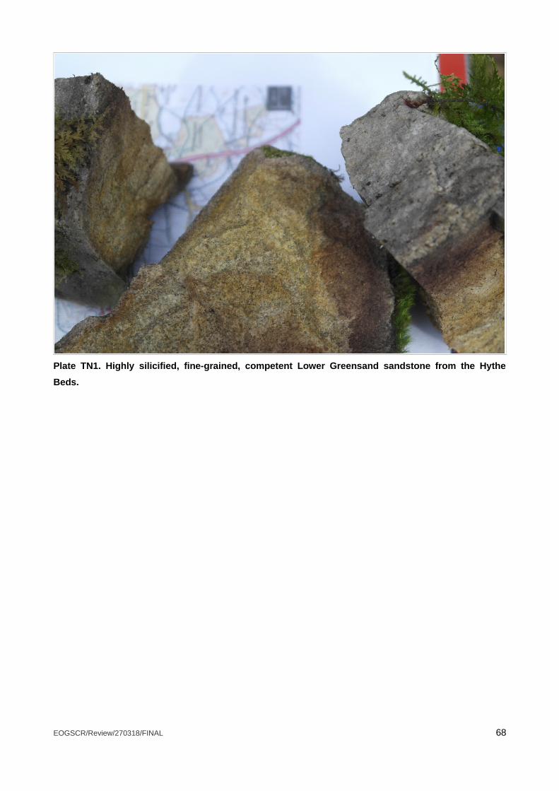
Plate TN1. Highly silicified, fine-grained, competent Lower Greensand sandstone from the Hythe
Beds.
EOGSCR/Review/270318/FINAL 68
APPENDIX TN1 – Results of the HW-ERA targeted literature review, describing specific texts
reviewed.
The literature was chosen based on the criterion that it should be applicable to onshore oil and gas
exploration in the EU and the UK.
The material chosen is applicable in its entirety or by parts of the project or subject studied.
Literature focusing on shale gas exploration operations overlap conventional methods by for example site
preparations, well construction and integrity, handling, storage and transportation of hazardous material and
well decommissioning (Amec Foster Wheeler Environment and Infrastructure UK Ltd, 2016; Environment
Agency, 2013).
Some of the literature reviewed is developed by, or for, the UK government and constitutes the basis for
reviewing the risk assessment contents and approach of the HW ERA. Other literature is added in an attempt
to broaden the comparison and raise other views possibly not present in the former material.
This study has predominantly focused on general guidelines or risk assessments. The material can be
divided into three groups:
1) General risk assessments on onshore oil and gas exploratory activities and shale gas exploratory
operations in the UK and Europe.
• Standard rules SR2015. No 1. The management of extractive waste, not including a waste
facility, generated from onshore oil and gas prospecting activities including drilling, coring,
leak off testing (LOT), acid wash and decommissioning but excluding hydraulic fracturing for
the production of oil or gas (using oil and water based drilling mud) (Environment Agency,
2016a; Environment Agency, 2010b).
A generic risk assessment for the management of onshore oil and gas prospecting operations in the form of
a spread sheet describing receptors, sources, harms, pathways, actions for risk management etc. The risk
assessment takes into account well drilling, construction and coring using water and or oil based drilling
fluids, leak off well testing, acid wash and decommissioning but excludes hydraulic fracturing. The spread
sheet accompanies a set of standard rules for the operation.
• Study on the assessment and management of environmental impacts and risks resulting
from the exploration and production of hydrocarbons. (Amec Foster Wheeler Environment and
Infrastructure UK Ltd, 2016).
A report presenting a generic risk assessment on conventional exploration and production in Europe. The
assessment is structured around five stages:
EOGSCR/Review/270318/FINAL 69
• Site identification and preparation• Well design, construction and completion• Development and Production• Project cessation, well closure and decommissioning• Project post closure and abandonment
The environmental aspects examined are:
• Groundwater contamination and other risks;• Surface water contamination;• Water resource depletion;• Releases to air;• Land take;• Biodiversity impacts;• Noise;• Visual Impact;• Seismicity, and• Traffic.
A qualitative assessment is provided with definitions of the levels of consequences and likelihoods. Risk
rankings were performed through expert judgement and relevant literature. The report also acknowledges
that a site-specific approach must be taken for each unique project. The report also includes a chapter
comparing the risks of hydraulic fracturing and
enhanced recovery techniques in conventional and unconventional onshore wells.
• Review of assessment procedures for shale gas well casing installation. Environment Agency.
(2010a).
This is a generic environmental risk assessment for shale gas exploratory operations in England. The
assessment covers stages from baseline monitoring to well decommissioning:
• Baseline monitoring• Water acquisition• Chemical mixing• Borehole integrity• Well injection• Flowback fluid management including residual material left in the well• Gas management• Offsite disposal or reuse• Well decommissioning
A qualitative assessment is given and probability and consequence categories are defined.
As mentioned above, a number of areas are considered transferable to conventional oil and gas exploration.
2) Guidelines, regulations and other types of governmentally produced material.
• Guidelines for Environmental Risk Assessment and Management, Green Leaves III. (DEFRA,
2011)
EOGSCR/Review/270318/FINAL 70

The Green Leaves III provides generic guidelines for the assessment and management of environmental
risks and presents a cyclical framework for risk management (Figure TNA1). The framework offers structure
to the questions and decisions related to the complex task of risk management and builds on four stages:
• Formulation of the problem• Risk assessment• Identification and apprising the management options available and, • Addressing the risk with the management strategy chosen.
The importance of iterating, communicate and learning is also stressed in the Green Leaves III. If an
implemented strategy to monitor risk is not effective the risk assessment and management process should
be iterated. Furthermore, the components of the assessment should be transparent and include stakeholders
when feasible. The guidelines also advice that suitable techniques to analyse and understand uncertainties
in the risk assessment are employed.
Figure TNA1. Framework presenting the cyclic process of risk assessment and management
according to the Green Leaves III (DEFRA, 2011)4.
4http://www.nationalarchives.gov.uk/doc/open-government-licence/version/3/ accessed 21/3/18
EOGSCR/Review/270318/FINAL 71

• Onshore oil and gas sector guidance. Version 1. (Environment Agency, 2016b).
The guide is provided for oil and gas companies and their consultants. It is intended to facilitate the process
of understanding what permits are required for onshore oil and gas operations in England. It considers
legislation and what is needed to comply, and where relevant, also the best available techniques that are to
be used to meet Regulatory requirements. The following activities are included:
• Constructing the well pad• Drilling exploratory wells• Flow testing and well stimulation, including hydraulic fracturing• Storing and handling crude oil• Treatment of waste gases (including flaring)• Handling, storage and disposal of produced waters and flowback fluid• Managing extractive wastes• Extraction of coal mine methane
• Onshore oil and gas exploration in the UK: regulation and best practice. (Department of Energy
and Climate Change, 2013).
The document presents a roadmap for facilitating understanding of the permitting and permissions process
for onshore exploratory gas and oil operations. The document is intended as an introduction.
3) Other literature on risk management and environmental impact .
Material from the Horizon2020-programme5. Frackrisk6, M4SHaleGas7, SC4E8,
ShaleXenvironmenT9, ShEER10.
Within the Horizon 2020 call it is stated that certain environmental and public health risks need to be better
understood, monitored and managed regarding subsurface operations related to unconventional
hydrocarbons. These are mainly related to water pollution due to for example insufficient underground
characterisation, inappropriate well casing and waste management but also air emissions and impacts linked
to transport, land and water use.
The M4ShaleGas, ShEER and Fracrisk projects intend to understand, prevent and mitigate potential risks
and impacts with shale gas exploration. While the ShaleXenvironmenT project´s major objective is to assess
the environmental footprint of shale gas exploration in Europe. The SC4E “aims to develop, test and
implement technologies needed for successfully detecting, quantifying and mitigating the risks connected
5European commission. Horizon 2020. https://ec.europa.eu/programmes/horizon2020/en/what-horizon-2020 15/3/2018
6 http://www.fracrisk.eu/ 15/3/2018
7M4ShaleGas. Measuring, monitoring, mitigating, managing the environmental impact of shale gas. http://www.m4shalegas.eu/home.html accessed 15/3/2018
8Science for clean energy. http://science4cleanenergy.eu/about/objectives/
9 https://shalexenvironment.org/ accessed 15/3/2018
10Shale gas exploration and exploitation induced risk. http://www.sheerproject.eu/ accessed 15/3/2018
EOGSCR/Review/270318/FINAL 72

with geo-energy operations in the sub-surface” and one of the specific objectives is to overcome knowledge
gaps within “the detection of failure of concrete casings, the quantification, prediction and eventual control of
fluid transport pathways in sub-surface rock formations and cement-based materials,…, and in the rate and
extent of fluid-rock-microbe interactions in subsurface systems” 4
A review on potential impact from shale gas exploitation infrastructure, draws from experiences of
comparative industries, therein conventional oil and gas, and related impact studies. The infrastructure
considered are the well pad, access roads, boreholes and pipelines and furthermore, spills, leaks,
biodiversity and transport are covered. It is suggested that mitigation measures should include locating new
boreholes close to existing infrastructure, using already disturbed ground, maintaining natural vegetation and
applying safety procedures of best practice (Clancy et al, 2016; Worral et al, 2017).
Furthermore, in Subsurface risk and impacts of shale gas operations (ter Heeg, 2017), providing a summary
of main hazards, impacts and risks, it is reported that the scale of operations involved is the most important
difference between unconventional and conventional hydrocarbon exploitation.
• A critical review of the risks to water resources from unconventional shale gas development
and hydraulic fracturing in the United States. (Vengosh et al., 2014)
The study presents a number of modes of water impact from shale gas extraction, for example:
• Shallow groundwater and surface water contamination from spills and leaks of wastewater
storage and open pits near drilling,
• Disposal of inadequately treated wastewater to local streams and accumulation of
contaminant residues in disposal sites,
• Shallow aquifer contamination through abandoned oil and gas wells and flow of gas and,
saline water directly from deep formation waters to shallow aquifers.
• Risk management of shale gas development and operations. (DNV, 2013).
The intention with this document is to establish recommendations for shale gas developments and
operations with regard to risk management for the safety of people and environment during all phases of
development and operation. The document for example considers:
• Risk management principles• Health and safety risk management• Environmental risk management• Well risk management• Water and energy resource management and• Infrastructure and logistics risk management
• Temporary shale gas exploration Preston New Road, Lancashire. Environmental risk
assessment. (Cuadrilla Bowlamd Ltd and ARUP, 2014).
EOGSCR/Review/270318/FINAL 73
A risk assessment performed for temporary shale gas exploration in Lancashire based on the Green Leaves
III (DEFRA, 2011). The categories of risk are connected to:
• Air quality• Archaeology and heritage• Ecology• Hydrogeology and contamination• Lighting• Traffic• Water resources• Induced seismicity• Waste• Landscape and visual amenity• Site management
Likelihood and consequences are described qualitatively. Furthermore, the estimated risk rating is described
in terms of acceptability.
• State of the art review of the environmental assessment and risks of underground geo-energy
resources exploitation. (Liu, W., Ramirez, A. (2017).
The paper aims to identify knowledge gaps within underground geo-energy resource exploitation.
Conclusions stated includes that for energy supply associated exploitation, the type of underground activities
and the exploited energy carriers affects impacts to the largest degree in a life-cycle perspective. Migration of
fluids used within the process and migration of the exploited energy carriers are identified as major hazards
with regard to the energy supply purpose.
• Hydraulic fracturing for oil and gas: Impacts from the hydraulic fracturing water cycle on
drinking water resources in the United States. (USEPA, 2016).
The goals are to assess the potential for impacts on the quality and quantity of drinking water caused by
hydraulic fracturing water cycle activities. Also, to identify factors affecting severity and frequency of such
impacts.
EOGSCR/Review/270318/FINAL 74


![The wellsite guide[1]](https://img.pdfslide.us/doc/110x75/579070081a28ab68749b9997/the-wellsite-guide1.jpg)