Embed Size (px)
Citation preview
American Journal of Modern Energy 2021; 7(4): 51-60 http://www.sciencepublishinggroup.com/j/ajme doi: 10.11648/j.ajme.20210704.12 ISSN: 2575-3908 (Print); ISSN: 2575-3797 (Online)
Review of Energy Storage Technologies for Compressed-Air Energy Storage
Ibrahim Nabil, Mohamed Mohamed Khairat Dawood*, Tamer Nabil
Mechanical Engineering Department, Suez Canal University, Ismailia, Egypt
Email address:
*Corresponding author
To cite this article: Ibrahim Nabil, Mohamed Mohamed Khairat Dawood, Tamer Nabil. Review of Energy Storage Technologies for Compressed-Air Energy
Storage. American Journal of Modern Energy. Vol. 7, No. 4, 2021, pp. 51-60. doi: 10.11648/j.ajme.20210704.12
Received: April 27, 2021; Accepted: May 19, 2021; Published: August 23, 2021
Abstract: Energy systems play a significant role in harvesting energy from several sources and converting it to the energy
forms needed for applications in numerous sectors, e.g., utility, industry, building, and transportation. In the coming years,
energy storage will play a key role in an efficient and renewable energy future; more than it does in today’s fossil-based energy
economy. There are different strategies for energy storage. Among these strategies, storage of mechanical energy via suitable
media is broadly utilized by human beings. Mechanical energy storage systems (MESS) are among the utmost effective and
sustainable energy storage systems. There are three main types of mechanical energy storage systems; pumped hydro, flywheel,
and compressed air. This review discusses the recent progress in mechanical energy storage systems focusing on compressed
air energy storage (CAES). It also discusses the advances and evolution in compressed air energy storage (CAES) technologies
which improve the thermal process and incorporate CAES with other subsystems to improve system efficiency and compares
these technologies in terms of their performance, capacity, response, and utilizations as well as the challenges facing CAES as
emissions that may harm the environment, the consumption of fossil fuels or requiring certain geological formations then
modifications and developments to overcome these challenges.
Keywords: Mechanical Energy, Energy Storage, Compressed Air Energy Storage,
Energy Storage Technologies and Applications
1. Introduction
Cumulatively, over years energy consumption has been
growing significantly. According to the published statistics
by the International Energy Agency (IEA), about 13,371
Million Tons of Oil Equivalent (Mtoe) of energy is supplied
worldwide in 2012. This is near 10% and 119% higher than the
statistics in 2009 and 1973 values respectively. Despite there is an
increasing tendency in the global energy supply, the percentage
share of fossil fuel has been declining gradually due to the
advances in renewable energy systems [1].
Energy storage is a crucial link in energy supply chain. For
example, actually there is no system that is 100%
thermodynamically efficient. The energy losses in different
systems happen in the Energy storage has many benefits. It is
important in energy management to reduce energy wastage
and maximize the efficiency of energy utilization of process
systems [2, 3].
Energy storage is expected to play a substantial role as the
world moves to a low carbon economy somewhere more
energy is predicted to be produced from renewable resources.
Renewable energy resources, especially solar and wind are
facing a main challenge as they occur intermittently which
creates unreliable steady energy supply. This can be attained
by storing the excess energy produced when the renewable
resources are available and re-use it again when the
renewable resources are not available [1].
2. Importance of Energy Storage
Energy storage has lots of benefits. Storage of secondary
energy systems as electricity and heat is important to reduce
the amount of primary energy forms (fossil fuels) that have
been consumed to generate them. This results in not only
decrease CO2 and other greenhouse gas emissions that lead to
global warming [5] but also help to preserve fossil fuels which
52 Ibrahim Nabil et al.: Review of Energy Storage Technologies for Compressed-Air Energy Storage
are supposed to be exhaustible. It can also play a essential role
in increasing the use of renewable, clean and irregular energy
resources such as wind energy, solar energy, and marine tidal
current to the grid as well as help in load shifting [4]. Energy
storage helps in the planning of power system, its operation
and frequency regulation [4, 5]. It helps to keep energy
systems stability, improve power quality in micro-grid systems
in addition match demand with supply [6].
There are many technologies used for energy storage drives.
These technologies can be generally categorized according to
the purpose for which the energy is stored. They include:
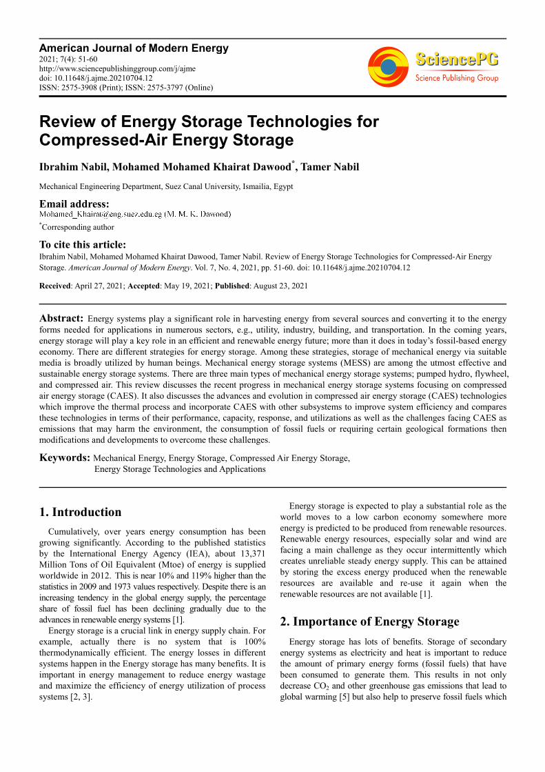
thermal energy storage and electrical energy storage. Figure 1
shows the diverse classes of energy storage technologies. From
the figure, it is shown that the technologies in which energy is
stored in the form of thermal energy and released in the
thermal form such as ice/chill water storage are categorized as
thermal energy storage technologies while those in which the
energy is stored in the form of thermal but released as
electrical energy such as liquid air energy storage are
categorized as electrical storage. In this review the emphasis is
on mechanical energy storage [1].
Figure 1. Energy storage technologies classification [7].
3. Mechanical Energy Storage Systems
Mechanical energy storage systems (MESS) stored
mechanical energy as kinetic energy or dynamic energy. They
have main advantage as they are fast with direct release of
the stored mechanical energy [8].
MESS are classified mainly to Pump hydro energy storage
(PHES); compressed air energy storage (CAES) and
Flywheel energy storage (FES) [9, 10].
3.1. Pump Hydro Energy Storage
PHES stored energy through pumping water from a low
tank to a high tank; the low tank is altitude wise much lower
than the high one [11]. In addition to the two tanks a PHES
has an electric motor to be used as a pump while charging or
used as a power generator while discharging [4]. The amount
of the stored energy is proportionate to the altitude difference
between the two tanks as well as the amount of stored water
[5]. Efficiency of PHES Storage system varies between 65%
to 85% [1, 5, 12].
3.2. Compressed Air Energy Storage
Operation concept of CAES is established on compressing
air using inexpensive energy; generated on low energy
demand times; and its future release onto a turbine for the
operation of an electric generator [4, 5]. The first CAES
system initiated operating in 1978 in Germany (290 MW).
Then it was followed by the Mclntoch CAES plant in
Alabama (110 MW) in 1991. These two systems are the only
operating CAES globally [12, 13].
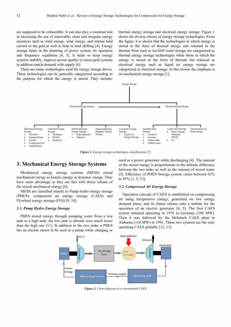
Figure 2. Chart diagram of a conventional CAES.
American Journal of Modern Energy 2021; 7(4): 51-60 53
A compressed air energy storage system (CAES) is
composed of a compressor; a storage tank and a turbine. The
turbines used in CAES for generating power are established
on Brayton’s thermodynamic cycle [14] Schematic diagram
of a conventional CAES is displayed in figure 2. The
operation of a CAES is much like to a common turbine. At
time of charging the generator works as a motor supplying
power to the air compressor. At time of discharging the
compressed air is place in the combustion chamber and then
is released on the turbine. The turbine role is to move the
electric power generator. Although CAES release CO2 they
can provide three times more electric power to the grip than a
common turbine for power generator; however consuming
the same among of fuel [4].
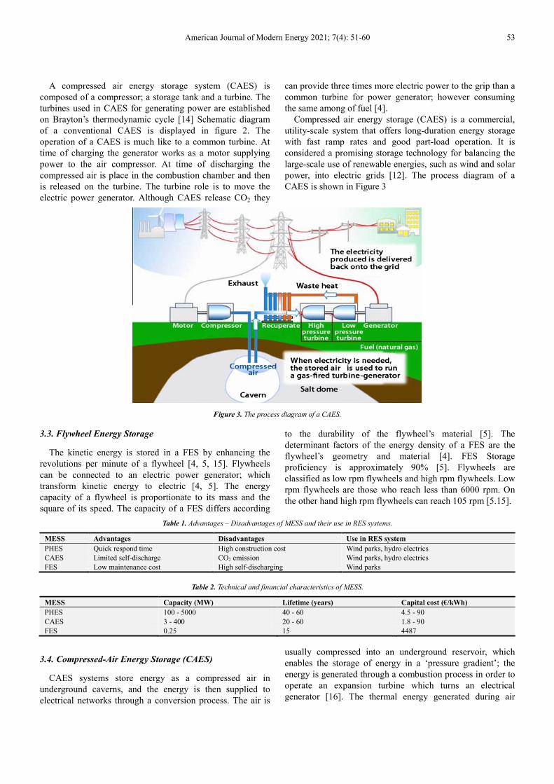
Compressed air energy storage (CAES) is a commercial,
utility-scale system that offers long-duration energy storage
with fast ramp rates and good part-load operation. It is
considered a promising storage technology for balancing the
large-scale use of renewable energies, such as wind and solar
power, into electric grids [12]. The process diagram of a
CAES is shown in Figure 3
Figure 3. The process diagram of a CAES.
3.3. Flywheel Energy Storage
The kinetic energy is stored in a FES by enhancing the
revolutions per minute of a flywheel [4, 5, 15]. Flywheels
can be connected to an electric power generator; which
transform kinetic energy to electric [4, 5]. The energy
capacity of a flywheel is proportionate to its mass and the
square of its speed. The capacity of a FES differs according
to the durability of the flywheel’s material [5]. The
determinant factors of the energy density of a FES are the
flywheel’s geometry and material [4]. FES Storage
proficiency is approximately 90% [5]. Flywheels are
classified as low rpm flywheels and high rpm flywheels. Low
rpm flywheels are those who reach less than 6000 rpm. On
the other hand high rpm flywheels can reach 105 rpm [5.15].
Table 1. Advantages – Disadvantages of MESS and their use in RES systems.
MESS Advantages Disadvantages Use in RES system
PHES Quick respond time High construction cost Wind parks, hydro electrics
CAES Limited self-discharge CO2 emission Wind parks, hydro electrics
FES Low maintenance cost High self-discharging Wind parks
Table 2. Technical and financial characteristics of MESS.
MESS Capacity (MW) Lifetime (years) Capital cost (€/kWh)
PHES 100 - 5000 40 - 60 4.5 - 90
CAES 3 - 400 20 - 60 1.8 - 90
FES 0.25 15 4487
3.4. Compressed-Air Energy Storage (CAES)
CAES systems store energy as a compressed air in
underground caverns, and the energy is then supplied to
electrical networks through a conversion process. The air is
usually compressed into an underground reservoir, which
enables the storage of energy in a ‘pressure gradient’; the
energy is generated through a combustion process in order to
operate an expansion turbine which turns an electrical
generator [16]. The thermal energy generated during air
54 Ibrahim Nabil et al.: Review of Energy Storage Technologies for Compressed-Air Energy Storage
compression (charging) is released directly to the atmosphere,
and during operation of decompression (discharging), the air
necessities to be reheated, usually with a fuel [17]. The
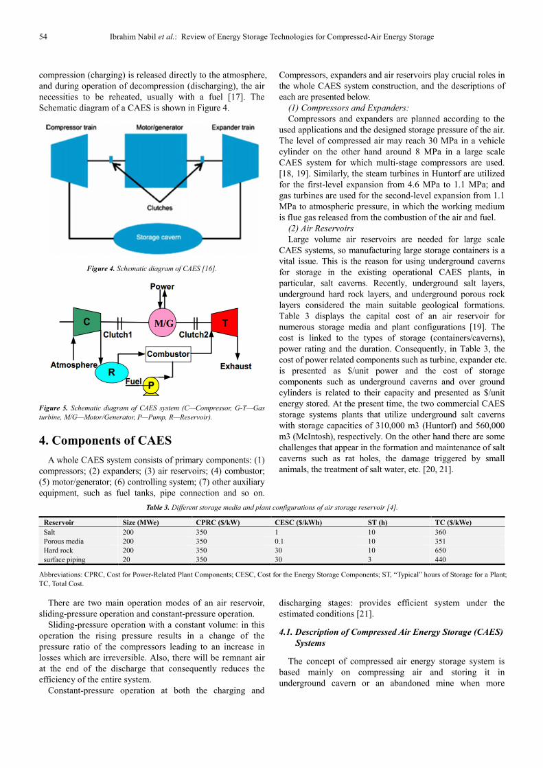
Schematic diagram of a CAES is shown in Figure 4.
Figure 4. Schematic diagram of CAES [16].
Figure 5. Schematic diagram of CAES system (C—Compressor, G-T—Gas
turbine, M/G—Motor/Generator, P—Pump, R—Reservoir).
4. Components of CAES
A whole CAES system consists of primary components: (1)
compressors; (2) expanders; (3) air reservoirs; (4) combustor;
(5) motor/generator; (6) controlling system; (7) other auxiliary
equipment, such as fuel tanks, pipe connection and so on.
Compressors, expanders and air reservoirs play crucial roles in
the whole CAES system construction, and the descriptions of
each are presented below.
(1) Compressors and Expanders:
Compressors and expanders are planned according to the
used applications and the designed storage pressure of the air.
The level of compressed air may reach 30 MPa in a vehicle
cylinder on the other hand around 8 MPa in a large scale
CAES system for which multi-stage compressors are used.
[18, 19]. Similarly, the steam turbines in Huntorf are utilized
for the first-level expansion from 4.6 MPa to 1.1 MPa; and
gas turbines are used for the second-level expansion from 1.1
MPa to atmospheric pressure, in which the working medium
is flue gas released from the combustion of the air and fuel.
(2) Air Reservoirs
Large volume air reservoirs are needed for large scale
CAES systems, so manufacturing large storage containers is a
vital issue. This is the reason for using underground caverns
for storage in the existing operational CAES plants, in
particular, salt caverns. Recently, underground salt layers,
underground hard rock layers, and underground porous rock
layers considered the main suitable geological formations.
Table 3 displays the capital cost of an air reservoir for
numerous storage media and plant configurations [19]. The
cost is linked to the types of storage (containers/caverns),
power rating and the duration. Consequently, in Table 3, the
cost of power related components such as turbine, expander etc.
is presented as $/unit power and the cost of storage
components such as underground caverns and over ground
cylinders is related to their capacity and presented as $/unit
energy stored. At the present time, the two commercial CAES
storage systems plants that utilize underground salt caverns
with storage capacities of 310,000 m3 (Huntorf) and 560,000
m3 (McIntosh), respectively. On the other hand there are some
challenges that appear in the formation and maintenance of salt
caverns such as rat holes, the damage triggered by small
animals, the treatment of salt water, etc. [20, 21].
Table 3. Different storage media and plant configurations of air storage reservoir [4].
Reservoir Size (MWe) CPRC ($/kW) CESC ($/kWh) ST (h) TC ($/kWe)
Salt 200 350 1 10 360
Porous media 200 350 0.1 10 351
Hard rock 200 350 30 10 650
surface piping 20 350 30 3 440
Abbreviations: CPRC, Cost for Power-Related Plant Components; CESC, Cost for the Energy Storage Components; ST, “Typical” hours of Storage for a Plant;
TC, Total Cost.
There are two main operation modes of an air reservoir,
sliding-pressure operation and constant-pressure operation.
Sliding-pressure operation with a constant volume: in this
operation the rising pressure results in a change of the
pressure ratio of the compressors leading to an increase in
losses which are irreversible. Also, there will be remnant air
at the end of the discharge that consequently reduces the
efficiency of the entire system.
Constant-pressure operation at both the charging and
discharging stages: provides efficient system under the
estimated conditions [21].
4.1. Description of Compressed Air Energy Storage (CAES)
Systems
The concept of compressed air energy storage system is
based mainly on compressing air and storing it in
underground cavern or an abandoned mine when more
American Journal of Modern Energy 2021; 7(4): 51-60 55
energy is accessible and exceed the needed quantity.
According to the energy demand, the stored compressed air is
released to a turbine to generate electricity. Caverns may
either be drilled in salt or rock formations, or utilizing
existing cavities such as aquifer strata. Such geological
formations do not exist all over and large steel tanks which
are utilized to maintain high pressures are sometimes
installed under the ground at a higher cost. Can be
economically attractive due to their capacity of compressed
air energy storage systems to shift time of energy use gives
an economic advantage in addition to the need to balance the
effects of intermittent renewable energy penetration in the
grid [23].
On the other hand using the excess available energy to store
liquefied air at cryogenic temperatures in low-pressure
completely insulated reservoirs is another alternative. In
comparison to compressed air, liquid air has much lower losses
because it could be kept at moderate pressures. Consequently, it
might be a superior option than compressed air for long-term
storage systems. Liquid air has other advantages over
compressed air as it is denser and with the opportunity to be
stored in smaller reservoirs. For a specified quantity of liquefied
air in a tank of 5000 m3, it is reported in a case study that the
CAES volume was approximately 310,000 m3 [24]. When
comparing between compressed air and liquefied air energy
storage systems it indicated that a higher efficiency for the
liquefied air energy storage systems [24]. To produce, the
simplest approach to obtain liquid air when excess energy is
existing is based on the Linde–Hampson cycle in which a Joule-
Thompson effect valve is used for the expansion. Other
variability of this cycle may also comprise cryogenic turbines
for expansion (e.g., Claude and Collins cycles) which lower the
operating pressures, and increase liquid air production amount as
well as efficiencies [25].
While discharging, liquefied air is pumped to high
pressure, evaporated and then heated to supply high pressure
air. There are two resources for heat provision, from ambient
temperature medium as air as well as from a higher-
temperature medium such as gases from natural gas
combustion. The specific work output and the system
efficiency can be improved through increasing the
temperature, making it near equivalent to other energy
storage technologies. Using air directly for combustion is an
alternative to increase the temperature. The air, or gas, from a
liquefied container can be expanded in turbines to generate
electricity. To improve the system efficiency authors
proposed various Methods to decrease liquefaction wastes
and external energy requirements of regasification of
liquefied air [26, 27, 28]. For instance, the use of the waste
cooling power from the liquid air evaporation stage in other
cycles (e.g., Rankine) can generate extra work and improve
the efficiency of system to more than 80% [25].
The cooled air can be used as a heat sink in a Brayton
cycle as well as in a cryogenic organic Rankine cycle. In a
Brayton cycle, the generated heat during air compression
before its liquefaction as waste heat could be stored and
utilized to heat the air again as passing through turbines as
well as to be as a source for heat. She et al. [26] propose a
Brayton cycle that utilizes the heat from liquefaction of air
and releases heat to the evaporator of a liquefied natural gas
storage system, therefore coupling the two systems for better
efficiency. The authors reported that system round-trip
efficiency is around 70%. Peng et al. [28] suggested packed
beds as direct contact heat exchangers to accumulate the
excess heat in the compression stage of liquefaction then
release it to the air in the expansion stage during discharging
process. Xie et al. [29] suggested that economic feasibility is
improbable for liquefied air energy storage systems without
the use of waste heat, and that increasing the feasibility with
larger plant installations. Reliant on how heat is controlled
and managed during compression as heat discharge and
earlier to the expansion stage as heat intake, there are three
different types of CAES: isothermal, diabatic and adiabatic.
CAES system has a RTE of 85%, with an expected life time
of about 20–40 years; it is considered a suitable possibility
for large-scale storage applications. There are many
challenges that CAES systems face which includes the
necessity for an underground cavern, dissipation of excess
heat into the atmosphere, consuming fossil fuels, and
production of pollutant emissions from the combustion
processes [30, 31].
The diabatic-CAES system has been described above;
however, recent technological efforts have led to
development of the following systems
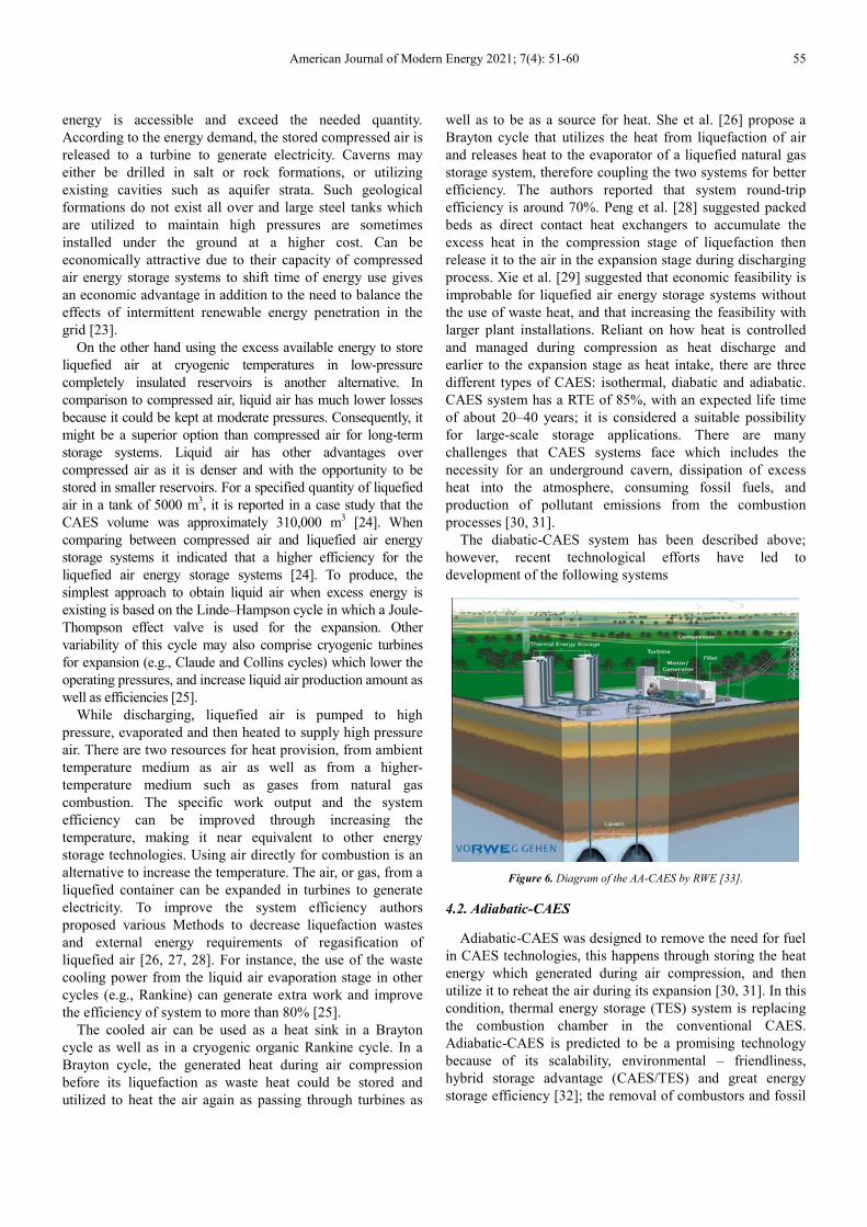
Figure 6. Diagram of the AA-CAES by RWE [33].
4.2. Adiabatic-CAES
Adiabatic-CAES was designed to remove the need for fuel
in CAES technologies, this happens through storing the heat
energy which generated during air compression, and then
utilize it to reheat the air during its expansion [30, 31]. In this
condition, thermal energy storage (TES) system is replacing
the combustion chamber in the conventional CAES.
Adiabatic-CAES is predicted to be a promising technology
because of its scalability, environmental – friendliness,
hybrid storage advantage (CAES/TES) and great energy
storage efficiency [32]; the removal of combustors and fossil
56 Ibrahim Nabil et al.: Review of Energy Storage Technologies for Compressed-Air Energy Storage
fuels also makes it more economic than the conventional
CAES. The main constituents of an adiabatic-CAES plant
include compressor, TES, underground cavern and air turbine.
These components can be configured into the needed storage
scale. From the most suitable thermal energy storage
materials in adiabatic-CAES system, Salt and concrete. The
world’s first adiabatic-CAES plant, stated to advanced
adiabatic-CAES (AACAES) demonstration plant, is
projected to go ‘on stream’ in Germany by 2016, by RWE
Power and its partners [33, 34]. The aim of the project is to
obtain system efficiencies of 70%. The Advanced adiabatic-
CAES (AA-CAES) by Rheinisch-Westfälisches
Elektrizitätswerk (RWE) is shown in Figure 6.
4.3. Isothermal CAES
Isothermal CAES this new technology tries to overcome
particular challenges with conventional adiabatic- or
adiabatic CAES [31], by elimination the need for fuel and
‘high temperature’ heat energy storage, which results in
improved RTE of (70–80%) and reducing the cost making it
more economic. In this system, the air is compressed without
any change in temperature, permitting minimal work for
compression while maximizing the work required for
expansion, through effective heat transfer with surroundings
of the air vessel [32].
4.4. Small-medium Scale CAES
Small-medium scale CAES large-scale CAES plants
usually require suitable geological formations for storing air
[33, 34]. However, small-medium scale CAES, with a
capacity of 1–10 MW, having artificial pressure vessels is a
more flexible CAES technology that don’t need to caverns
and TES [35, 36]. This technology is suitable for a tri-
generation purpose, including distributed electricity
generation and storage, air-cycle heating and cooling in a
combined process [98], which leads to a significant reduction
in energy costs and greenhouse gas emissions in the coming
future.
4.5. Underwater/Ocean-CAES
Underwater/ocean-CAES this storage system is a
promising option in the absence of underground cavern,
which can be integrated with ‘offshore’ renewable energy
resources such as tides, wind and waves [31]. The
compressed air is kept in an underwater air storage chamber
installed on the seabed; the pressure of the compressed air is
maintained constant requiring no pressure throttling, thus,
allowing efficient release of energy from the compressed air.
The authors in Ref. have planned constant-pressure CAES
combined with pumped hydro storage, and conceptual design
of ocean compressed air energy storage (OCAES),
respectively. Also, an energy storage solution is patented by
Hydrostat, based in Canada. This technology uses ‘semi-
adiabatic’ underwater-CAES (UW-CAES) with a potential to
store large-scale electricity for around 4–48 h, at applications
between 1 and 50 MW [37]. UW-CAES is promising for
prospect applications of micro grids and DERs. It is also
projected to be delivered at optimal costs for the intended
markets.
5. The Current Development of CAES
Technologies
The drive for evolving CAES technology is actually to
achieve sustainable energy and to decrease emissions, so
current technology development target is to avoid using fossil
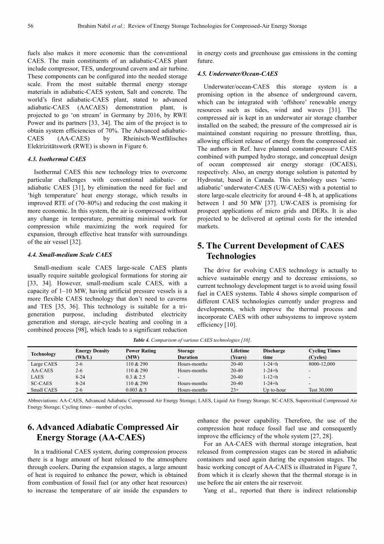
fuel in CAES systems. Table 4 shows simple comparison of
different CAES technologies currently under progress and
developments, which improve the thermal process and
incorporate CAES with other subsystems to improve system
efficiency [10].
Table 4. Comparison of various CAES technologies [10].
Technology Energy Density
(Wh/L)
Power Rating
(MW)
Storage
Duration
Lifetime
(Years)
Discharge
time
Cycling Times
(Cycles)
Large CAES 2-6 110 & 290 Hours-months 20-40 1-24+h 8000-12,000
AA-CAES 2-6 110 & 290 Hours-months 20-40 1-24+h -
LAES 8-24 0.3 & 2.5 - 20-40 1-12+h -
SC-CAES 8-24 110 & 290 Hours-months 20-40 1-24+h -
Small CAES 2-6 0.003 & 3 Hours-months 23+ Up to-hour Test 30,000
Abbreviations: AA-CAES, Advanced Adiabatic Compressed Air Energy Storage; LAES, Liquid Air Energy Storage; SC-CAES, Supercritical Compressed Air
Energy Storage; Cycling times—number of cycles.
6. Advanced Adiabatic Compressed Air
Energy Storage (AA-CAES)
In a traditional CAES system, during compression process
there is a huge amount of heat released to the atmosphere
through coolers. During the expansion stages, a large amount
of heat is required to enhance the power, which is obtained
from combustion of fossil fuel (or any other heat resources)
to increase the temperature of air inside the expanders to
enhance the power capability. Therefore, the use of the
compression heat reduce fossil fuel use and consequently
improve the efficiency of the whole system [27, 28].
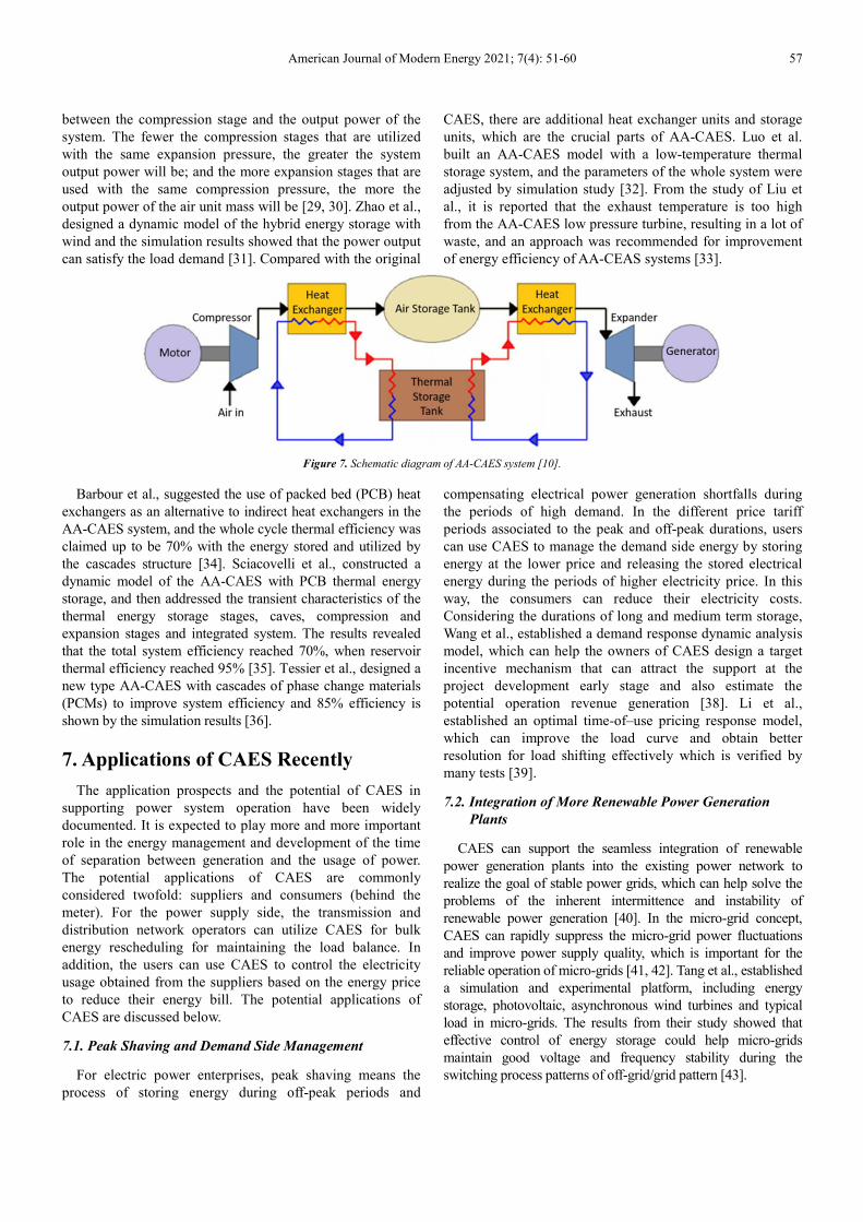
For an AA-CAES with thermal storage integration, heat
released from compression stages can be stored in adiabatic
containers and used again during the expansion stages. The
basic working concept of AA-CAES is illustrated in Figure 7,
from which it is clearly shown that the thermal storage is in
use before the air enters the air reservoir.
Yang et al., reported that there is indirect relationship
American Journal of Modern Energy 2021; 7(4): 51-60 57
between the compression stage and the output power of the
system. The fewer the compression stages that are utilized
with the same expansion pressure, the greater the system
output power will be; and the more expansion stages that are
used with the same compression pressure, the more the
output power of the air unit mass will be [29, 30]. Zhao et al.,
designed a dynamic model of the hybrid energy storage with
wind and the simulation results showed that the power output
can satisfy the load demand [31]. Compared with the original
CAES, there are additional heat exchanger units and storage
units, which are the crucial parts of AA-CAES. Luo et al.
built an AA-CAES model with a low-temperature thermal
storage system, and the parameters of the whole system were
adjusted by simulation study [32]. From the study of Liu et
al., it is reported that the exhaust temperature is too high
from the AA-CAES low pressure turbine, resulting in a lot of
waste, and an approach was recommended for improvement
of energy efficiency of AA-CEAS systems [33].
Figure 7. Schematic diagram of AA-CAES system [10].
Barbour et al., suggested the use of packed bed (PCB) heat
exchangers as an alternative to indirect heat exchangers in the
AA-CAES system, and the whole cycle thermal efficiency was
claimed up to be 70% with the energy stored and utilized by
the cascades structure [34]. Sciacovelli et al., constructed a
dynamic model of the AA-CAES with PCB thermal energy
storage, and then addressed the transient characteristics of the
thermal energy storage stages, caves, compression and
expansion stages and integrated system. The results revealed
that the total system efficiency reached 70%, when reservoir
thermal efficiency reached 95% [35]. Tessier et al., designed a
new type AA-CAES with cascades of phase change materials
(PCMs) to improve system efficiency and 85% efficiency is
shown by the simulation results [36].
7. Applications of CAES Recently
The application prospects and the potential of CAES in
supporting power system operation have been widely
documented. It is expected to play more and more important
role in the energy management and development of the time
of separation between generation and the usage of power.
The potential applications of CAES are commonly
considered twofold: suppliers and consumers (behind the
meter). For the power supply side, the transmission and
distribution network operators can utilize CAES for bulk
energy rescheduling for maintaining the load balance. In
addition, the users can use CAES to control the electricity
usage obtained from the suppliers based on the energy price
to reduce their energy bill. The potential applications of
CAES are discussed below.
7.1. Peak Shaving and Demand Side Management
For electric power enterprises, peak shaving means the
process of storing energy during off-peak periods and
compensating electrical power generation shortfalls during
the periods of high demand. In the different price tariff
periods associated to the peak and off-peak durations, users
can use CAES to manage the demand side energy by storing
energy at the lower price and releasing the stored electrical
energy during the periods of higher electricity price. In this
way, the consumers can reduce their electricity costs.
Considering the durations of long and medium term storage,
Wang et al., established a demand response dynamic analysis
model, which can help the owners of CAES design a target
incentive mechanism that can attract the support at the
project development early stage and also estimate the
potential operation revenue generation [38]. Li et al.,
established an optimal time-of–use pricing response model,
which can improve the load curve and obtain better
resolution for load shifting effectively which is verified by
many tests [39].
7.2. Integration of More Renewable Power Generation
Plants
CAES can support the seamless integration of renewable
power generation plants into the existing power network to
realize the goal of stable power grids, which can help solve the
problems of the inherent intermittence and instability of
renewable power generation [40]. In the micro-grid concept,
CAES can rapidly suppress the micro-grid power fluctuations
and improve power supply quality, which is important for the
reliable operation of micro-grids [41, 42]. Tang et al., established
a simulation and experimental platform, including energy
storage, photovoltaic, asynchronous wind turbines and typical
load in micro-grids. The results from their study showed that
effective control of energy storage could help micro-grids
maintain good voltage and frequency stability during the
switching process patterns of off-grid/grid pattern [43].
58 Ibrahim Nabil et al.: Review of Energy Storage Technologies for Compressed-Air Energy Storage
7.3. Applications to Smart-Grids and Wind Energy Network
Smart-grids, as the future direction and trend of the electric
power industry, aim to achieve energy management in both
directions, that is, from both supply and consumption with
the support of internet and big data technology [44, 45].
Traditionally, consumers have passively accepted the
electricity supplied to them so it is a direction of supply and
consumption relationship; however, smart-grids will
transform this structure by involving the active selection of
supply, integration of local generation and dispatching energy
storage sources. Rifkin, a famous American economist,
believed that energy internet would be the core in the third
industrial revolution, which will have a great influence on the
development of society [46]. The energy internet is called
smart-grid V2.0 by Li, et al., and energy storage is thought to
be as the main enabling technologies of energy conversions
and their integrated applications [2].
7.4. Applications to Compressed Air Engines
The compressed air energy can be converted into other
different forms of mechanical energy through compressed air
engines as in air-powered vehicles [47, 48]. Chen et al.,
performed a detailed a recent review on the advances in
research and development of air-powered vehicles and
revealed that the current work should be based on the
principle and the structure optimization of air-powered
automobile engines, the distribution forms and the reducing
pressure technology [49].
7.5. Applications in Other Fields
In the case of power supply system failure, CAES systems
can be used as a back-up power or uninterrupted power
supply (UPS), which can supply adequate power to important
users, such as banks, data processing centers, hospitals and
other important sectors [6, 19]. CAES systems could provide
the capacity of black-start in a power shutdown condition.
For example, the Huntorf plant offers black-start power to the
nuclear units located near the North Sea [49].
8. Conclusions
The paper explained the types of energy storage systems
with interest in mechanical energy storage. This review
focused on the operating principles and concepts of CAES
and presented a detailed comprehensive review on CAES
technology development. The paper discussed the basic and
vital information for CAES description, design, challenges
and developments. This paper covers the importance of
CAES, the recent advances in materials and information in
CAES development and efforts recently. The following
conclusions are made
1) The most basic Conventional CAES technologies are
suitable commercially for large-scale applications.
However, they face some challenges as they require
certain geological formations and fossil fuels.
2) The utilization of waste heat generated by air
compression process for air expansion is expected to
offer an emission-free storage solution, by reducing the
need for fossil fuels. This technology offers a much
better system efficiency therefore recommending
adiabatic-CAES for micro grids recently. However,
further research is required for their extensive
applications in the future. System efficiency of 70% is
being achieved by RWE Power for its AA-CAES plant.
3) Small-medium scale CAES is also a promising
development of CAES technology; it eliminates the
need for geological formations. This technology is
expected to thrive in the near future because of its tri-
generation capacity, which reduce carbon emissions and
energy costs, and improve distributed electricity
generation.
9. Recommendations for Future
From the previous review it is recommended;
1) To utilize Compresses air energy storage in large scale
systems as it provides reasonable efficiency however it
faces some challenges.
2) To use advanced CAES technologies to overcome the
common challenges as emissions that may harm the
environment and the consumption of fossil fuels.
3) Using advanced CAES technologies is recommended to
get better thermal process and better system efficiency.
4) Advanced CAES technologies can be integrated with
reasonable intermittent energy plants to give stable
grids and overcome the intermittent renewable sources.
5) CAES can be converted into other forms of mechanical
energy in addition to its use as backup power.
6) To utilize efficient and cost effective Adiabatic CAES in
micro grids as they provide an emission-free storage
appliance.
7) Use isothermal technology as they improve RTE of 70-
80% with low cost so they have economic advantage
over conventional CAES.
8) In absence of caverns it is better to use small-medium
CAES technology especially for a tri-generation
purpose due to its flexibility with no need for certain
geological configurations.
Nomenclature
IEA International Energy Agency
MTOE Million Tonnes of Oil Equivalent
CO2 Carbon dioxide
CAES Compressed air energy storage
MESS Mechanical energy storage systems
MW Mega Watt
PHES Pump hydro energy storage
FES Flywheel energy storage
RES Renewable energy storage system
TES Thermal energy storage system
ACAES Adiabatic compressed air energy storage
AACAES Advanced adiabatic-CAES
American Journal of Modern Energy 2021; 7(4): 51-60 59
ICAES Isothermal CAES
OCAES Ocean compressed air energy storage
UW-CAES Underwater-CAES
LAES Liquid Air Energy Storage
SC-CAES Supercritical Compressed Air Energy Storage
PCB Packed bed heat exchangers
PCMs Phase change materials
UPS Uninterrupted power supply
RTE Round trip efficiency
References
[1] Aneke, M. and M. Wang (2016). "Energy storage technologies and real life applications – A state of the art review." Applied Energy 179: 350-377.
[2] Lovell J. Biofuels: Europe’s 2nd-biggest coal-fired power plant will turn to wood from North America. E & E Publishing, LLC; 2013. Available at: Available from: www.eenews.net.
[3] EC Biomass. Biomass fuel pellets. EC Biomass; 2015. Available at: Available from: www.ecbiomass.co.za].
[4] Mahlia TMI, Saktisahdan TJ, Jannifar A, Hasan MH, Matseelar HSC. A review of available methods and developments on energy storage; technology update. Renew Sustain Energy Rev 2014; 33: 532–45.
[5] Kousksou T, Bruel P, Jamil A, El Rhafiki T, Zeraouli Y. Energy storage: application and challenges. Sol Energy Mater Sol Cells 2013; 120: 59–80.
[6] Castillo A, Gayme DF. Grid-scale energy storage applications in renewable energy integration: a survey. Energy Convers Manage 2014; 87: 885–94.
[7] SBC. SBC energy institute analysis based on US DOE energy storage program planning document, 2011.
[8] Khodadoost Arani AA, Karami H, Gharehpetian GB, Hejazi MSA. Review of flywheel energy storage systems structures and applications in power systems and microgrids. Renew Sust Energ Rev 2016; 69: 9–18. https://doi.org/10.1016/j.rser. 2016.11.166.
[9] Guezgouz Mohammed, Jurasz Jakub, Bekkouche Bennaissa, Ma Tao, Javed Muhammad Shahzad, Kies Alexander. Optimal hybrid pumped hydro-battery storage scheme for off-grid renewable energy systems. Energ Convers Manage 2019; 199: 112046. https://doi.org/10.1016/j.enconman.2019.112046.
[10] Mahmoud, M., et al. (2020). "A review of mechanical energy storage systems combined with wind and solar applications." Energy Conversion and Management 210.
[11] S. M. Mousavi, F. Faraji, A. Majazi, K. Al-Haddad, A comprehensive review of Flywheel Energy Storage System technology, Renew. Sust. Energy Rev. 67 (2017) 477–490.
[12] Liu, W., et al. (2014). "Analysis and Optimization of a Compressed Air Energy Storage—Combined Cycle System." Entropy 16 (6): 3103-3120.
[13] Venkataramani G, Parankusam P, Ramalingam V and Wang J 2016. A review on compressed air energy storage - A pathway for smart grid and polygeneration. Renewable and Sustainable Energy Reviews 62. ScienceDirect, 895–907.
[14] Guney M S and Tepe Y 2017. Classification and assement of energy storage systems. Renewable and Sustainable Energy Reviews 75. ScienceDirect, 1187–97.
[15] Koohi-Fayegh, S. and M. A. Rosen (2020). "A review of energy storage types, applications and recent developments." Journal of Energy Storage 27.
[16] Fertig E, Apt J. Economics of compressed air energy storage to integrate wind power: a case study in ERCOT. Energy Pol 2011; 39 (5): 2330–42.
[17] Diaz- Gonzalez F, Sumper A, Gomis-Bellmunt O, Villafafila-Robles R. A review of energy storage technologies for wind power applications. Renew Sustain Energy Rev 2012; 16: 2154–71.
[18] Zhang, X.; Chen, H.; Liu, J.; Li, W.; Tan, C. Research process in compressed air energy storage system: A review. Energy Storage Sci. Technol. 2012, 1, 26–40.
[19] Wasbari, F.; Bakar, R. A.; Gan, L. M.; Tahir, M. M.; Yusof, A. A. A review of compressed-air hybrid technologyin vehicle system. Renew. Sustain. Energy Rev. 2017, 67, 935–953 [CrossRef].
[20] Greenblatt, J. B.; Succar, S.; Denkenberger, D. C.; Williams, R. T.; Robert, H. S. Baseload wind energy: Modelingthe competition between gas turbines and compressed air energy storage for supplemental generation. Energy Policy 2007, 35, 1474–1492 [CrossRef].
[21] Pei, P.; Korom, S. T.; Ling, K.; He, J.; Gil, A. Thermodynamic impact of aquifer permeability on theperformance of a compressed air energy storage plant. Energy Convers. Manag. 2015, 97, 340–350 [CrossRef].
[22] Guo, C.; Zhang, K.; Li, C. Subsurface system design and feasibility analysis of compressed air Energy storagein aquifers. J. Tongji Univ. Nat. Sci. 2016, 44, 1107–1112.
[23] M. Budt, D. Wolf, R. Span, J. Yan, A review on compressed air energy storage: basic principles, past milestones and recent developments, Appl. Energy 170 (2016) 250–268.
[24] P. Krawczyk, Ł. Szabłowski, S. Karellas, E. Kakaras, A. Badyda, Comparative thermodynamic analysis of compressed air and liquid air energy storage systems, Energy 142 (2018) 46–54.
[25] R. F. Abdo, H. T. C. Pedro, R. N. N. Koury, L. Machado, C. F. M. Coimbra, M. P. Porto, Performance evaluation of various cryogenic energy storage systems, Energy 90 (1) (2015) 1024–1032.
[26] M. Antonelli, S. Barsali, U. Desideri, R. Giglioli, F. Paganucci, G. Pasini, Liquid air energy storage: potential and challenges of hybrid power plants, Appl Energy 194 (2017) 522–529.
[27] X. She, X. Peng, T. Zhang, L. Cong, Y. Ding, Preliminary study of Liquid Air Energy Storage integrated wit LNG cold recovery, Energy Procedia 158 (2019) 4903–4908.
[28] H. Peng, X. Shan, Y. Yang, X. Ling, A study on performance of a liquid air energy storage system with packed bed units, Appl. Energy 211 (2018) 126–135.
[29] C. Xie, Y. Hong, Y. Ding, Y. Li, J. Radcliffe, An economic feasibility assessment odecoupled energy storage in the UK: with liquid air energy storage as a case study, Appl. Energy 225 (2018) 244–257.
60 Ibrahim Nabil et al.: Review of Energy Storage Technologies for Compressed-Air Energy Storage
[30] Bradbury K. Energy storage technology review. Duke University; 2010, p. 1–33.
[31] Young-Min K, Jang-Hee L, Seok-Joon K, Daniel F. Potential and evolution of compressed air energy storage: energy and exergy analyses. Entropy 2012; 14: 1501–21.
[32] Lim SD, Mazzoleni AP, Park J, Ro PI, Quinlan B. Conceptual design of ocean compressed air energy storage system. Proc Conf Oceans 2012: 1–8.
[33] Advanced adiabatic compressed air energy storage (AA-CAES). Energy Storage Association; 2013.
[34] ADELE-adiabatic compressed-air energy storage for electricity supply. RWE Power; 2010.
[35] Chen H, Zhang X, Liu J, Tan C. Compressed air energy storage. InTechOpen 2013: 101–12.
[36] Grazzini G, Milazzo. A thermodynamic analysis of multistage adiabatic CAES. Proc IEEE 2012; 100 (2): 461–72.
[37] Underwater compressed air energy storage: Islands and microgrids. White paper. Hydrostor; 2014. p. 1–13.
[38] Wang, B.; Yang, X.; Yang, S. Demand response performance and potential system dynamic analysis based onthe long and medium time dimensions. Proc. CSEE 2015, 35, 6368–6377.
[39] Li, C.; Xu, Z.; Ma, Z. Optimal time-of-use electricity price model considering customer demand response. Proc. CSU-EPSA 2015, 27, 11–16.
[40] Ghalelou, A.; Fakhi, A. P.; Nojavan, S.; Majidi, M.; Hatami, H. A stochastic self-scheduling program forcompressed air energy storage (CAES) of renewable energy sources (RESs) based on a demand responsemechanism. Energy Convers. Manag. 2016, 120, 388–396 [CrossRef].
[41] Yang, X.; Su, J.; Lv, Z.; Liu, H.; Li, R. Overview on micro-grid. Proc. CSEE 2014, 34, 57–70.
[42] Lu, Z.; Wang, C.; Min, Y.; Zhou, S.; Lv, J.; Wang, Y. Overview on microgrid research. Autom. Electr. Power Syst. 2007, 31, 100–107.
[43] Tang, X.; Deng, W.; Qi, Z. Research on Grid-connected/islanded seamless transition of microgrid based onenergy storage. Trans. China Electrotech. 2011, 26, 279–284.
[44] Zhang, D.; Miao, X.; Liu, L.; Zhang, Y.; Liu, K. Research on development strategy for smart grid big data. Proc. CSEE 2015, 35, 2–12.
[45] Wang, C.; Sun, W.; Yi, T.; Yan, Z.; Zhang, Y. Review on energy storage application planning and benefit evaluation methods in smart grid. Proc. CSEE 2013, 33, 33–41.
[46] Rifkin, J. The Third Industrial Revolution: How Lateral Power Is Transforming Energy, the Economy, and the World, 3rd ed.; Palgrave Macmillan: New York, NY, USA, 2011; pp. 107–161.
[47] Chen, Y.; Xu, H.; Tao, G.; Wang, X.; Liu, H.; Jia, G. Research and progress of the compressed air power vehicle. Chin. J. Mech. Eng. 2002, 38, 7–11 [CrossRef].
[48] Xu, H.; Yu, X.; Wang, L.; Fang, Y.; Fan, Z.; Dou, W.; Li, D. Exergy analysis on compressed air engine. Trans. Chin. Soc. Agric. Eng. 2016, 32, 42–49.
[49] Raju, M.; Khaitan, S. K. Modeling and simulation of compressed air storage in caverns: A case study of theHuntorf plant. Appl. Energy 2012, 89, 474–481 [CrossRef].