Embed Size (px)
Citation preview
Hindawi Publishing CorporationJournal of NanomaterialsVolume 2013, Article ID 789289, 22 pageshttp://dx.doi.org/10.1155/2013/789289
Review ArticleA Review of the Effect of Processing Variables on the Fabricationof Electrospun Nanofibers for Drug Delivery Applications
Viness Pillay,1 Clare Dott,1 Yahya E. Choonara,1 Charu Tyagi,1 Lomas Tomar,1
Pradeep Kumar,1 Lisa C. du Toit,1 and Valence M. K. Ndesendo2
1 Department of Pharmacy and Pharmacology, Faculty of Health Sciences, University of the Witwatersrand,7 York Road, Parktown, Johannesburg 2193, South Africa
2 School of Pharmacy and Pharmaceutical Sciences, St. John’s University of Tanzania, Dodoma, Tanzania
Correspondence should be addressed to Viness Pillay; [email protected]
Received 21 November 2012; Accepted 20 December 2012
Academic Editor: Lianjun Wang
Copyright © 2013 Viness Pillay et al. This is an open access article distributed under the Creative Commons Attribution License,which permits unrestricted use, distribution, and reproduction in any medium, provided the original work is properly cited.
Electrospinning is a fast emerging technique for producing ultrafine fibers by utilizing electrostatic repulsive forces. The techniquehas gathered much attention due to the emergence of nanotechnology that sparked worldwide research interest in nanomaterialsfor their preparation and application in biomedicine and drug delivery. Electrospinning is a simple, adaptable, cost-effective, andversatile technique for producing nanofibers. For effective and efficient use of the technique, several processing parameters need tobe optimized for fabricating polymeric nanofibers. The nanofiber morphology, size, porosity, surface area, and topography can berefined by varying these parameters. Such flexibility and diversity in nanofiber fabrication by electrospinning has broadened thehorizons for widespread application of nanofibers in the areas of drug and gene delivery, wound dressing, and tissue engineering.Drug-loaded electrospun nanofibers have been used in implants, transdermal systems, wound dressings, and as devices for aidingthe prevention of postsurgical abdominal adhesions and infection. They show great promise for use in drug delivery provided thatone can confidently control the processing variables during fabrication.This paper provides a concise incursion into the applicationof electrospun nanofibers in drug delivery and cites pertinent processing parameters that may influence the performance of thenanofibers when applied to drug delivery.
1. Introduction
Electrospinning is a simple and versatile technique thatutilizes electrostatic forces to produce very fine fibers ofpolymer ranging from submicron to nanometer sizes. Thetechnique can be applied to generate fibers of a wide arrayof polymer types—synthetic [1], natural [2], biodegradable[3, 4], nondegradable [5], or their blends [3, 6]. Althoughthere are other conventional techniques for polymeric fiberfabrication such as phase separation [7], self-assembly [8–10],template synthesis [11, 12], andmechanical drawing [13], elec-trospinning has gainedmuch importance and is the preferredtechnique since it is relatively ease, cost effective, requiressimple tooling, and is applicable for producing ultrafine fiberswith simple step-up production that is not easily achievablewith other conventional fiber-forming techniques. During
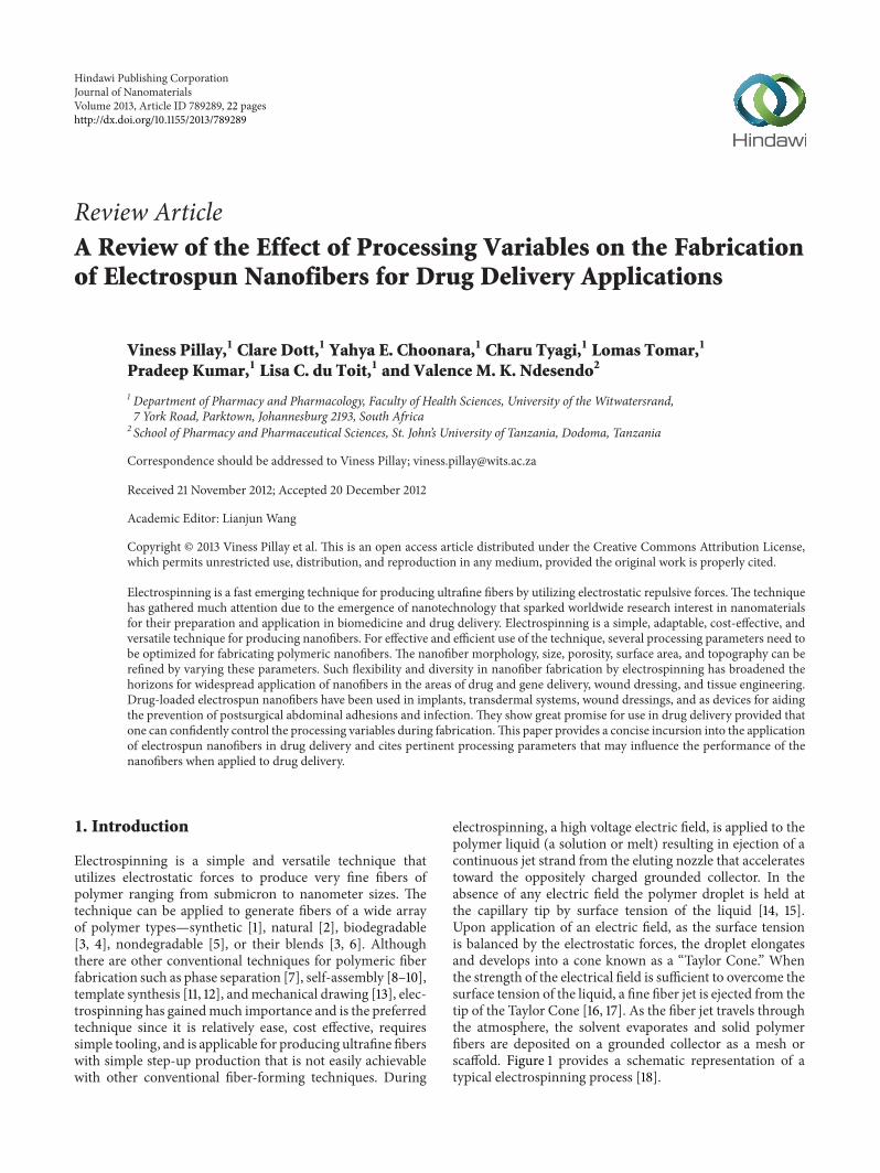
electrospinning, a high voltage electric field, is applied to thepolymer liquid (a solution or melt) resulting in ejection of acontinuous jet strand from the eluting nozzle that acceleratestoward the oppositely charged grounded collector. In theabsence of any electric field the polymer droplet is held atthe capillary tip by surface tension of the liquid [14, 15].Upon application of an electric field, as the surface tensionis balanced by the electrostatic forces, the droplet elongatesand develops into a cone known as a “Taylor Cone.” Whenthe strength of the electrical field is sufficient to overcome thesurface tension of the liquid, a fine fiber jet is ejected from thetip of the Taylor Cone [16, 17]. As the fiber jet travels throughthe atmosphere, the solvent evaporates and solid polymerfibers are deposited on a grounded collector as a mesh orscaffold. Figure 1 provides a schematic representation of atypical electrospinning process [18].
2 Journal of Nanomaterials
Fibre mat
Taylor cone
Fibre formationHigh voltagesupply
Syringe driver
Polymer solution
Figure 1: Schematic of a typical electrospinning setup showing theTaylor cone and SEM image of an electrospun mat. Adapted fromWallace et al. [18].
Fibers produced by conventional spinning methods arelengthened and thinned by being subjected to rheological,gravitational, tensile, inertial or aerodynamic forces [19].In electrospinning, the induced charges under the appliedfield creates tensile forces in the axial direction of the flowof the polymer jet that results in fiber spinning [19, 20].Recent experiments and theoretical studies have revealed thatthe jet, after travelling a short distance, becomes unstableand starts whipping as a consequence of interaction betweenthe applied external electrostatic field of attraction and therepulsive forces of the surface charges within the jet [19, 21].These interactions result in an increase in the fiber lengthand subsequent decrease in fiber diameter by many-foldcompared to fibers produced by other methods. The addedadvantage’s of electrospun fibers that render themwith a widerange of applicability include the high surface to volume ratio,high porosity, and interconnected porous networks that areformed [15, 19, 22].
The technique of electrospinning was first observed byRayleigh in 1897 and investigated in detail by Zeleny inthe early 1900s. However, electrospinning only surfaced as afeasible, small fiber diameter fabrication technique in 1934after patented by Formhals [23–30]. Bherdwaj and Kundu[23] patented the electrospinning process and a device thatconsisted of a moveable fiber-collector, such as a mandrel,to collect fibers in a stretched form. However, the distancebetween the jet and collector was relatively small and thefibers were unable to dry completely before reaching thecollector. This resulted in the fibers sticking to each otherand to the collector surface [27]. Formhals [28], in his secondpatent, improved the drawbacks associated with his earlierapparatus. Follow-up patents of Formhals [29] pertainedto improvements related to the control over the length ofthe produced fibers, formation of composite fibers by anelectrospinning process that involved the deposition of spunfibers onto a base fiber [29], and increase of the fiber strengthby drawing fibers through a rotating funnel [30].
After much fundamental research on the basics of theelectrospinning process, researchers investigated the effectsof various processing variables on the structural morphol-ogy and properties of electrospun fibers [14, 31, 32]. Adeeper understanding of apparently relative correlations ofvarious processing parameters and its impact on the fiber
morphology and properties resulted in tailoring polymericfibers of small diameter with desirable surface and bulkproperties. This led to the evolvement of the applicationof electrospun nanofibers in diverse fields. In electronics,electrospun nanofibers have been used as anode material inlithium ion batteries [33, 34], as fine conducting fibers andmagnetic materials [35–37], in electronic micro- and nano-devices [38, 39], and as optical and electrical nanomaterials[40]. Electrospun nanofibers have an application as a catalyticsubstrate due to their high surface area per unit mass [41–43]. Electrospun nonwoven mats have long been used forair filtration and have been successfully fabricated as highperformance air filters such as High Efficiency ParticulateAir (HEPA) filters [44, 45] and filters with a high filtrationefficiency and low air resistance [46].
Nanofibrous materials have also been investigated fortheir superior absorption and adsorption potential and maybe applied for water absorption [47] and adsorption ofpollutants such as toluene and benzene [48]. In addition,electrospun nanofibrous membranes have been employedin the fabrication of sensors for the detection of gases [49,50], chemical substances such as urea [51], and drugs suchas anticancer agents (e.g., daunorubicin) [52]. Biomedically,electrospun nanofibers have received much attention inthe areas of drug delivery [53, 54], gene delivery [55, 56],prevention of postoperative adhesions [57], wound dressings[58, 59], and tissue engineering [60, 61]. Tissue engineeringapplications of electrospun nanofibers include artificial vas-cular graft constructs [1, 62, 63], as well as the engineeringof neural tissue [64–66], tendon and ligament tissue [67, 68],and bone tissue [69, 70]. This paper delves into the effects ofprocessing parameters on electrospun nanofibermorphologyand characteristics with emphasis onmodulating the porosityand morphology of the fibers and mesh for pharmaceuticalapplications. In addition, a brief is provided on other relatedor potential applications of electrospun nanofibers.
2. The Process of Electrospinning
The process of electrospinning actually has its origin fromthe established process of electrospraying that utilizes thesame principle of applying an electric potential to a polymerliquid and causing a jet of liquid to accelerate from a capillarytip toward an oppositely charged collector [23]. When theliquid to which the potential is applied has a low viscosity,the jet during its trajectory will break up due to the surfacetension resulting in the formation of polymer droplets insteadof fibers [22, 71]. This is known as electrospraying and hasapplication in the production of fine aerosol particles in thesubmicron size range and has practically been applied inpesticide and electrostatic sprayers [72, 73]. However, if theliquid to which the potential is applied has a greater viscosity(∼1–200 poise), the jet will be less likely to break up becausethe greater viscoelastic forces would dampen the Rayleighbreakingmechanism as the so-called viscoelastic forces neveract against the surface tension. It will then travel towardsthe grounded target in the form of a continuous jet finallydepositing as nanofibers, and this constitutes electrospinning
Journal of Nanomaterials 3
[23]. Apart from the surface tension and forces of thepolymer solution, that is, electrospun, there are various otherprocessing variables that are deciding factors for the finaloutcome of the process and the performance of the fabricatednanofibers.
Although the electrospinning process appears to betechnically simple with ease of adaptability, a number ofprocessing variables need to be regulated in order to generatenanofibers instead of droplets or beaded morphologies. Themajor challenge of the electrospinning process lies in the opti-mization of these parameters to achieve desirable nanofibermorphology and properties. These processing variables canbe broadly termed as follows: the applied voltage, solutionflow-rate, polymer concentration, solution viscosity, nature ofsolvent, solution conductivity, and the distance between thecapillary and collector.
2.1. Effect of Changes in the Applied Voltage. Taylor [16]observed that the difference between the applied voltage thatwould cause a polymer drop to become unstable and thatwhich would cause it to become conical in shape is verysmall. Any further increase in voltage beyond a critical valueleads to the ejection of a polymer jet from the apex of thecone. This critical value of applied voltage varies with thetype of polymer solution and there is an optimum range ofthe applied voltage or the electric field strength for a givenpolymer-solvent system within which nanofiber formation isdesirable. An electric field that may be weaker or strongerthan this critical value will result in beaded morphologiesor even inhibit polymer jet initiation. In general, with anincrease in the applied voltage beyond a critical value, thenanofiber diameter decreases initially and then increasesafter a definite point [74]. The initial decrease in nanofiberdiameter is attributed to a higher degree of jet stretching incorrelation to increased charge repulsion within the jet and astrong external electric field as a consequence of an increasein the applied voltage. In a study by Baumgarten [14], the jetlength of a polymer solution at the optimal feed rate increasedwhen the applied voltage was increased. At a capillary-to-collector gap of 50mm, the nanofiber diameter initiallydecreased to a minimum and then increased with increasingvoltage. At a gap of 75mm, the decrease in nanofiber diameterto aminimumwas not as apparent and the diameter increasedslightly in response to an increase in the applied voltage. Theoptimum capillary feed rate also increased with an increasein the applied voltage.
Deitzel and coworkers [22] examined the effect of theapplied voltage on a poly(ethylene oxide) (PEO)/water sys-tem. They showed that the applied voltage had a significanteffect on the shape of the droplet from which the fiber jetoriginated. If all other variables except the applied voltageremain constant, an increase in the current would thereforegenerally reflect an increase in the flow-rate between thecapillary and collector. An increase in the applied voltagein the range of 5.5–9.0 kV resulted in an increase in thespinning current for the PEO/water system prototyped. Atan applied voltage of 5.5 kV the jet initiated from the apex ofthe Taylor Cone and nanofibers were regular free of defects.
Between 5.5 kV and 7.0 kV, the current increased slowly withan increase in the applied voltage. At these lower voltagesthe nanofiber jet still ejected from the Taylor Cone at thebottom of the solution droplet (at the capillary end) andthere were few bead defects associated with the nanofibersthat had a cylindrical morphology. Greater than 7.0 kV thecurrent increased dramatically in response to the higherapplied voltage and the jet was ejected from the Taylor Coneat the capillary tip. Beads on the nanofibers became moreprevalent at an applied voltage of 7.0 kV and their densityincreased further at 9.0 kV, when the jet was ejected frominside the capillary tip. Similar observations of an increase inbead defects with an increase in the applied voltage have beenreported by other researchers [75, 76].
Meechaisue and coworkers [77] investigated the effect ofthe applied voltage on the electrospun nanofibermorphologyof a poly(desaminotyrosyl-tyrosine ethyl ester carbonate)poly(DTE carbonate) solution at two different concentra-tions (15% W/V and 20% W/V). For the 15% W/V polymersolution beaded nanofibers were mostly observed at appliedvoltages between 10.0 kV and 15.0 kV, with the bead densitydecreasing as the voltage increased until smooth nanofiberswere obtained at voltages between 20.0 kV and 25.0 kV. Ata polymer concentration of 20% W/V the nanofibers weresmooth at all applied voltages and the nanofiber diameterincreased with increasing applied voltage in both cases forpoly(DTE carbonate).The increase in nanofiber diameterwasrelated to an increase in the flow-rate of the polymer solutionas a result of the higher applied voltage.
In a similar study undertaken by Zong and coworkers[78], the effect of the applied voltage on the morphology ofelectrospun poly(D,L-lactic acid) (PDLLA) nanofibers wasinvestigated. Jet formationwas initiated at a voltage of 16.0 kVandwas not stable at voltages<20.0 kV.At a voltage of 20.0 kV,the jet originated from the tip of the TaylorCone andminimalbead formation was noted within the nanofiber structure. Asthe voltagewas increased to 25.0 kV, the droplet volume of thepolymer solution reduced and bead formation became moreprevalent. Beads that were formed at 25.0 kV had smallerdiameters and higher density. When the applied voltage wasfurther increased to 30.0 kV, the polymer droplet completelydisappeared and the jet emerged from the tip of the capillary.The nanofibers obtained at this voltage had greater diametersand the formed beads became more spherical in shape.
2.2. Effect of Modifying the Solution Flow-Rate. The flow-rate of the polymer solution through a capillary influencesthe nanofiber diameter, porosity, and geometry of the elec-trospun nanofibers. As observed by Deitzel and coworkers[22] as well as Zong and coworkers [78], in separate studiesconducted to investigate the effect of an increase in theapplied voltage, the volume of the polymer drop within theTaylor Cone decreased with an increase in voltage, eventuallyleading to the nanofiber jet being ejected from inside thecapillary resulting in bead defects [74]. Therefore, in orderto maintain the Taylor Cone shape at the capillary tip andavoid bead defects, a minimum flow-rate of the polymer isrequired in order to replace the solution that is lost when
4 Journal of Nanomaterials
the nanofiber jet is ejected [26]. Megelski and coworkers[79] demonstrated an increase in diameter and pore sizeof electrospun polystyrene (from THF solution) nanofibers,to be associated with an increased flow-rate of the polymersolution. As the flow-rate increased, the available polymervolume was high which increased the nanofiber diameteralong with an increase in pore size. When the flow-rate wastoo high, the nanofibers were unable to dry completely beforereaching the collector and higher bead defects were thereforeobserved. Flattened ribbon-like nanofiber morphology mayalso result from incomplete drying of nanofibers due to ahigh flow-rate [79]. In another study by Zong and coworkers[78], it was shown that the lower the solution flow-rate, thesmaller the diameter of the resultant electrospun nanofibersand bead defects. Beads that were formed on nanofibers thatwere electrospun using a higher solution flow-rate had largerdiameters. This was attributed to the larger droplet at theend of the capillary, due to the higher flow-rate, resultingin the solution having a faster trajectory and resulting inincomplete drying and the formation of bead defects.Theronand coworkers [80] investigated the effect of solution flow-rate on electric current and surface charge density. Theyfound that an increase in flow-rate simultaneously increasedthe electric current and decreased the surfaces charge density.
2.3. Effect of Polymer Concentration and Solution Viscosity.Theprocess of electrospinning is based on uniaxial stretchingof a charged jet of polymer solution. At lower polymericconcentrations, due to the effect of the applied voltage andsurface tension of the polymeric solution, the charged jetfragments into discrete droplets before reaching the col-lector [81, 82]. At an increased polymeric concentration,as the viscosity increases the chain entanglement betweenpolymeric chains improves and nanofibers are formed. Theconcentration of polymer in the solution to be electrospunthus has an effect on both the viscosity and surface tensionof the liquid which ultimately decides the electrospinnabilityof the solution into nanofiber with increased diameters as thepolymer concentration increases. However at concentrationsbeyond a certain limit, the viscosity of the solution becomesexceedingly high, disrupting the flow of the polymer solutionthrough the capillary [81, 82].
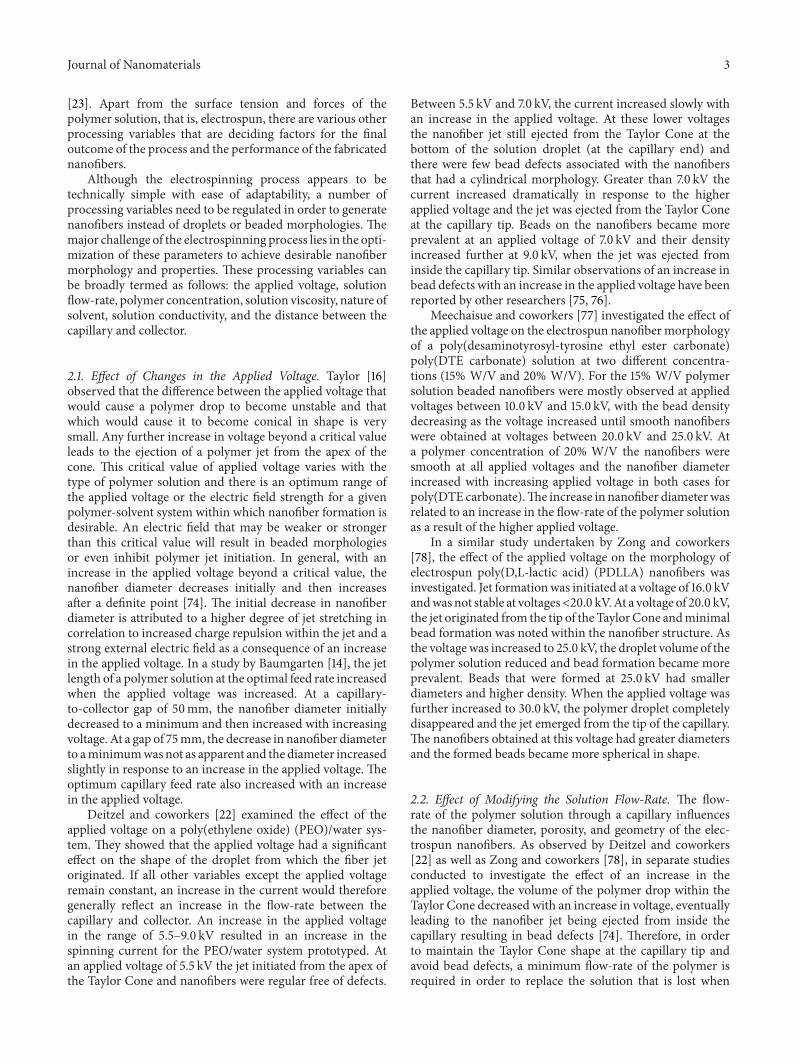
Doshi and Reneker [15] investigated the effect of vis-cosity on the electrospinning of aqueous PEO solutions.They observed that nanofibers were formed from solutionswith viscosities between 800 and 4000 cp. Below 800 cp,the nanofiber jet fragmented into droplets and >4000 cpnanofiber formation was difficult since the solution dehy-drated at the tip of the capillary. Nanofiber formation there-fore occurred in an optimum range of solution viscosity asdictated by an optimum polymer concentration. Further-more, the effect of change in viscosity of PEO solutions onthe appearance of bead defects in electrospun nanofiberswas investigated by Fong and coworkers [83]. They reportedthat with an increase in solution viscosity, the bead diameterincreased while the density of beads decreased. At greaterviscosities the bead shape became less spherical and morespindle-like, resulting in nanofiber formation with dimin-ished bead defects (Figure 2). A high surface tension of the
solution at lower levels of polymer concentration causedthe fiber jet to fragment into droplets. Viscoelastic forcescompeted with the surface tension in the nanofiber jet andan increase in viscosity therefore favored the formation ofsmooth nanofibers. In reports on electrospinning of poly-acrylonitrile solutions, nanofiber formation occurred at asolution viscosity range of 1.7–215 cp. As the solution viscosityincreased in this range, jet length and nanofiber diameterincreased and the drop at the end of the capillary changedfrom hemispherical to conical shape [14]. However, theviscosities in the upper range resulted in incomplete dryingof the polymer nanofiber thereby influencing themorphologyof the formed nanofibers.
Meechaisue and coworkers [77] examined the effectof different concentrations of poly(DTE carbonate) onelectrospun nanofiber formation. At a concentration of5% W/V (2.5 cp), mainly droplets were formed since theviscoelastic forces at this concentration were not sufficientto overcome the repulsive forces of charge, resulting inthe fiber jet fragmenting into droplets. At higher polymerconcentrations, the viscoelastic forces were sufficient toprevent fragmenting of the jet. Smooth nanofibers withbead defects were reported at a polymer concentration of10% w/v (14.8 cp) and almost completely smooth nanofibersat 15% W/V (50.5 cp). It was proposed that the repul-sive forces from the charge within the fiber jet resultedin stretching and therefore a smaller nanofiber diameterat lower concentrations was observed. At a higher poly-mer concentration of 20% W/V (196 cp), the viscoelasticforce in the nanofiber jet resisted the stretching repulsiveforces of charge, resulting in an increase in nanofiberdiameter [77].
Deitzel and coworkers [22] also in their work on the elec-trospinning of aqueous PEO solutions reported the optimumpolymer concentration range to be between 4 and 10% W/Vfor nanofiber formation. Below this range surface tensionwasthe detrimental factor and a combination of nanofibers anddroplets were reported. At lower concentrations within theuseful range, nanofibers had irregular morphologies alongwith bundles and junctions due to inadequate drying beforereaching the collector. At higher concentrations within theuseful range, the nanofiberswere regular and cylindrical, withfewer junctions and bundles due to adequate drying beforereaching the collector and the lower solvent content. Beyondthe concentration of 10% w/v, the flow of the polymersolution through the capillary could not be controlled dueto cohesion, and nanofiber formation was inhibited at such ahigh viscosity [22]. Zong and coworkers [78] obtained similarpatterns in attempting to electrospin PDLLA solutions ofdifferent concentrations and examining its effects on theresulting nanofiber morphology. They obtained a mixtureof large bead defects and nanofibers on electrospinningPDLLA solutions of concentration <20% W/V. At polymerconcentrations>40% W/V the viscositywas too high to allowelectrospinning. As the concentration and hence viscosityincreased between these two extremes, the nanofibers pro-duced were more uniform and the bead defects acquiredlarger diameters and became more spindle-shaped. It cantherefore be concluded that viscosity and surface tension
Journal of Nanomaterials 5
(a) (b) (c)
(d) (e) (f)
(g) (h)
Figure 2: Morphology of electrospun PEO nanofibers (in water) at varying electrospinning solution viscosities. (a) 13 centipoise, (b) 32centipoise, (c) 74 centipoise, (d) 160 centipoise, (e) 289 centipoise, (f) 527 centipoise, (g) 1250 centipoise, and (h) 1835 centipoise (electricfield: 0.7 kV/cm). Adapted from Fong et al. [83].
often determines the useful range of polymer concentrationsin electrospinning for a given polymer.
2.4. Effect of Solvent Selection. The choice of solvent is criticalfor a particular polymer to solubilize and be transformedinto nanofibers through electrospinning. Two importantconsiderations for selecting a solvent are the solubility of thepolymer in the solvent and the boiling point of the solventas indicative of its volatility. Generally, volatile solvents arethe preferred choice as they facilitate dehydration of thenanofibers during trajectory from the capillary tip to thecollector surface owing to their lower boiling point and hencerapid evaporation rate. However, highly volatile solvents withvery low boiling points should be avoided as they may evap-orate at the capillary tip and thereby result in clogging andobstructing the flow-rate of the polymer solution. Solventswith high boiling points may not dehydrate completely prior
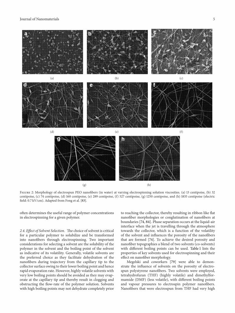
to reaching the collector, thereby resulting in ribbon like flatnanofiber morphologies or conglutination of nanofibers atboundaries [74, 84]. Phase separation occurs at the liquid-airinterface when the jet is travelling through the atmospheretowards the collector, which is a function of the volatilityof the solvent and influences the porosity of the nanofibersthat are formed [74]. To achieve the desired porosity andnanofiber topographies a blend of two solvents (co-solvents)with different boiling points can be used. Table 1 lists theproperties of key solvents used for electrospinning and theireffect on nanofiber morphology.
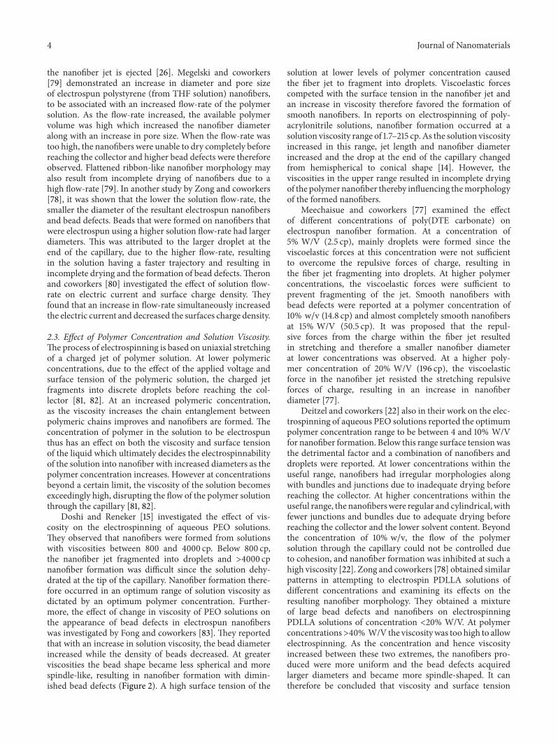
Megelski and coworkers [79] were able to demon-strate the influence of solvents on the porosity of electro-spun polystyrene nanofibers. Two solvents were employed,tetrahydrofuran (THF) (highly volatile) and dimethylfor-mamide (DMF) (less volatile), with different boiling pointsand vapour pressures to electrospin polymer nanofibers.Nanofibers that were electrospun from THF had very high
6 Journal of Nanomaterials
Table 1: Solvent properties and the resulting fiber morphology.
Solvent Boilingpoint (∘C) Other properties Fiber morphology Ref.
DCM 39.8 Low dielectric constant, high surfacetension Beaded, large diameter [77, 85]
Chloroform 61.2 High intrinsic viscosityBeaded at very low polymer concentration, smoothat higher concentration [86]
Methanol 64.7 High dielectric constantSmall fiber diameter with ↑methanol concentrationuntil 50% then ↑ fiber diameter [77]
THF 66 High dipole moment, good conductivity Smooth and beaded, ribbon-like, high pore density [78, 87]Ethyl acetate 77.1 High dielectric constant, fair conductivity Smooth and beaded, ribbon-like [87]
Ethanol 78.3Low surface tension, high intrinsicviscosity Smooth, large diameter [83, 85,
86]
MEK 79.6 High dipole moment, good conductivity Flat, ribbon-like, very few beads [87]Dichloroethane 83.5 High dipole moment, fair conductivity Smooth and beaded, C-shaped [87]Water 100 Low intrinsic viscosity Beaded, small diameter [83, 86]
DMF 153 High dipole moment, high conductivity,low intrinsic viscosity Smooth and beaded, round [86, 87]
(DCM: dichloromethane; THF: tetrahydrofuran; MEK: methyl ethyl ketone; DMF: dimethylformamide).
(a) (b)
(c) (d)
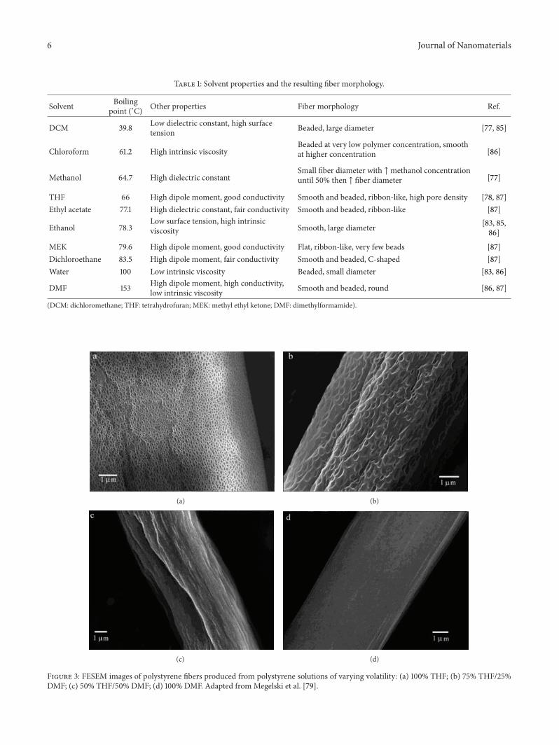
Figure 3: FESEM images of polystyrene fibers produced from polystyrene solutions of varying volatility: (a) 100% THF; (b) 75% THF/25%DMF; (c) 50% THF/50% DMF; (d) 100% DMF. Adapted fromMegelski et al. [79].
Journal of Nanomaterials 7
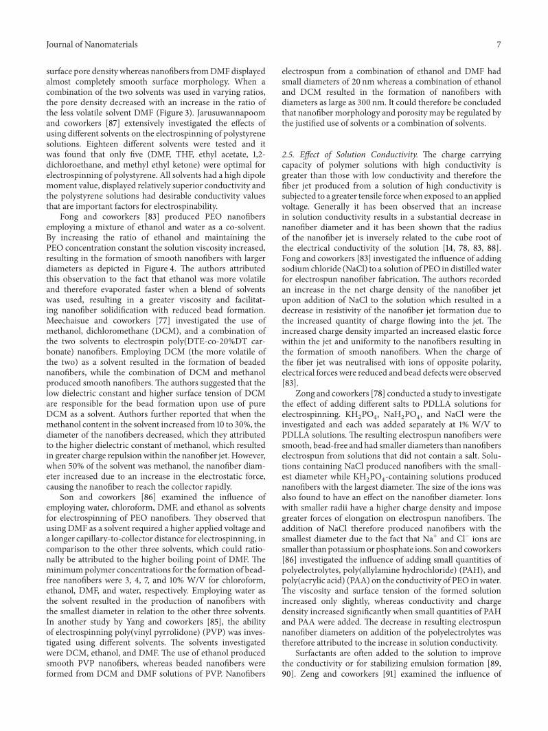
surface pore density whereas nanofibers fromDMFdisplayedalmost completely smooth surface morphology. When acombination of the two solvents was used in varying ratios,the pore density decreased with an increase in the ratio ofthe less volatile solvent DMF (Figure 3). Jarusuwannapoomand coworkers [87] extensively investigated the effects ofusing different solvents on the electrospinning of polystyrenesolutions. Eighteen different solvents were tested and itwas found that only five (DMF, THF, ethyl acetate, 1,2-dichloroethane, and methyl ethyl ketone) were optimal forelectrospinning of polystyrene. All solvents had a high dipolemoment value, displayed relatively superior conductivity andthe polystyrene solutions had desirable conductivity valuesthat are important factors for electrospinability.
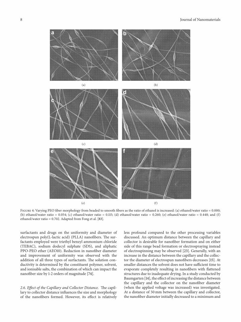
Fong and coworkers [83] produced PEO nanofibersemploying a mixture of ethanol and water as a co-solvent.By increasing the ratio of ethanol and maintaining thePEO concentration constant the solution viscosity increased,resulting in the formation of smooth nanofibers with largerdiameters as depicted in Figure 4. The authors attributedthis observation to the fact that ethanol was more volatileand therefore evaporated faster when a blend of solventswas used, resulting in a greater viscosity and facilitat-ing nanofiber solidification with reduced bead formation.Meechaisue and coworkers [77] investigated the use ofmethanol, dichloromethane (DCM), and a combination ofthe two solvents to electrospin poly(DTE-co-20%DT car-bonate) nanofibers. Employing DCM (the more volatile ofthe two) as a solvent resulted in the formation of beadednanofibers, while the combination of DCM and methanolproduced smooth nanofibers. The authors suggested that thelow dielectric constant and higher surface tension of DCMare responsible for the bead formation upon use of pureDCM as a solvent. Authors further reported that when themethanol content in the solvent increased from 10 to 30%, thediameter of the nanofibers decreased, which they attributedto the higher dielectric constant of methanol, which resultedin greater charge repulsionwithin the nanofiber jet. However,when 50% of the solvent was methanol, the nanofiber diam-eter increased due to an increase in the electrostatic force,causing the nanofiber to reach the collector rapidly.
Son and coworkers [86] examined the influence ofemploying water, chloroform, DMF, and ethanol as solventsfor electrospinning of PEO nanofibers. They observed thatusing DMF as a solvent required a higher applied voltage anda longer capillary-to-collector distance for electrospinning, incomparison to the other three solvents, which could ratio-nally be attributed to the higher boiling point of DMF. Theminimumpolymer concentrations for the formation of bead-free nanofibers were 3, 4, 7, and 10% W/V for chloroform,ethanol, DMF, and water, respectively. Employing water asthe solvent resulted in the production of nanofibers withthe smallest diameter in relation to the other three solvents.In another study by Yang and coworkers [85], the abilityof electrospinning poly(vinyl pyrrolidone) (PVP) was inves-tigated using different solvents. The solvents investigatedwere DCM, ethanol, and DMF. The use of ethanol producedsmooth PVP nanofibers, whereas beaded nanofibers wereformed from DCM and DMF solutions of PVP. Nanofibers
electrospun from a combination of ethanol and DMF hadsmall diameters of 20 nm whereas a combination of ethanoland DCM resulted in the formation of nanofibers withdiameters as large as 300 nm. It could therefore be concludedthat nanofiber morphology and porosity may be regulated bythe justified use of solvents or a combination of solvents.
2.5. Effect of Solution Conductivity. The charge carryingcapacity of polymer solutions with high conductivity isgreater than those with low conductivity and therefore thefiber jet produced from a solution of high conductivity issubjected to a greater tensile forcewhen exposed to an appliedvoltage. Generally it has been observed that an increasein solution conductivity results in a substantial decrease innanofiber diameter and it has been shown that the radiusof the nanofiber jet is inversely related to the cube root ofthe electrical conductivity of the solution [14, 78, 83, 88].Fong and coworkers [83] investigated the influence of addingsodium chloride (NaCl) to a solution of PEO in distilledwaterfor electrospun nanofiber fabrication. The authors recordedan increase in the net charge density of the nanofiber jetupon addition of NaCl to the solution which resulted in adecrease in resistivity of the nanofiber jet formation due tothe increased quantity of charge flowing into the jet. Theincreased charge density imparted an increased elastic forcewithin the jet and uniformity to the nanofibers resulting inthe formation of smooth nanofibers. When the charge ofthe fiber jet was neutralised with ions of opposite polarity,electrical forces were reduced and bead defects were observed[83].
Zong and coworkers [78] conducted a study to investigatethe effect of adding different salts to PDLLA solutions forelectrospinning. KH
2PO4, NaH
2PO4, and NaCl were the
investigated and each was added separately at 1% W/V toPDLLA solutions. The resulting electrospun nanofibers weresmooth, bead-free and had smaller diameters than nanofiberselectrospun from solutions that did not contain a salt. Solu-tions containing NaCl produced nanofibers with the small-est diameter while KH
2PO4-containing solutions produced
nanofibers with the largest diameter. The size of the ions wasalso found to have an effect on the nanofiber diameter. Ionswith smaller radii have a higher charge density and imposegreater forces of elongation on electrospun nanofibers. Theaddition of NaCl therefore produced nanofibers with thesmallest diameter due to the fact that Na+ and Cl− ions aresmaller thanpotassiumor phosphate ions. Son and coworkers[86] investigated the influence of adding small quantities ofpolyelectrolytes, poly(allylamine hydrochloride) (PAH), andpoly(acrylic acid) (PAA) on the conductivity of PEO in water.The viscosity and surface tension of the formed solutionincreased only slightly, whereas conductivity and chargedensity increased significantly when small quantities of PAHand PAA were added. The decrease in resulting electrospunnanofiber diameters on addition of the polyelectrolytes wastherefore attributed to the increase in solution conductivity.
Surfactants are often added to the solution to improvethe conductivity or for stabilizing emulsion formation [89,90]. Zeng and coworkers [91] examined the influence of
8 Journal of Nanomaterials
(a) (b)
(c) (d)
(e) (f)
Figure 4: Varying PEO fiber morphology from beaded to smooth fibers as the ratio of ethanol is increased: (a) ethanol/water ratio = 0.000;(b) ethanol/water ratio = 0.054; (c) ethanol/water ratio = 0.115; (d) ethanol/water ratio = 0.260; (e) ethanol/water ratio = 0.448; and (f)ethanol/water ratio = 0.702. Adapted from Fong et al. [83].
surfactants and drugs on the uniformity and diameter ofelectrospun poly(L-lactic acid) (PLLA) nanofibers. The sur-factants employed were triethyl benzyl ammonium chloride(TEBAC), sodium dodecyl sulphate (SDS), and aliphaticPPO-PEO ether (AEO10). Reduction in nanofiber diameterand improvement of uniformity was observed with theaddition of all three types of surfactants. The solution con-ductivity is determined by the constituent polymer, solvent,and ionisable salts, the combination of which can impact thenanofiber size by 1-2 orders of magnitude [74].
2.6. Effect of the Capillary and Collector Distance. The capil-lary to collector distance influences the size and morphologyof the nanofibers formed. However, its effect is relatively
less profound compared to the other processing variablesdiscussed. An optimum distance between the capillary andcollector is desirable for nanofiber formation and on eitherside of this range bead formation or electrospraying insteadof electrospinning may be observed [23]. Generally, with anincrease in the distance between the capillary and the collec-tor the diameter of electrospun nanofibers decreases [15]. Atsmaller distances the solvent does not have sufficient time toevaporate completely resulting in nanofibers with flattenedstructures due to inadequate drying. In a study conducted byBaumgarten [14], the effect of increasing the distance betweenthe capillary and the collector on the nanofiber diameter(when the applied voltage was increased) was investigated.At a distance of 50mm between the capillary and collector,the nanofiber diameter initially decreased to a minimum and
Journal of Nanomaterials 9
then increased with increasing voltage. At a gap of 75mm,the decrease in nanofiber diameter to a minimum was notapparent and the diameter increased slightly in response toan increase in the applied voltage. Doshi and Reneker [15]reported a decrease in nanofiber diameter with an increase inthe distance up to 30mm, beyond which the fiber jet becametoo small and unstable. Megelski and coworkers [79] notedno significant change in nanofiber diameter with a changein distance between the capillary and the collector. However,they reported an initiation of bead formation as the distancedecreased.
3. The Application of Electrospun Nanofibersin Drug Delivery Systems Design
Electrospinning has gained much attention in fabricatingnanofibers that have found application as drug carriers fordrug delivery systems. There are two main features of elec-trospun nanofibers (configured as nanomats) which makethem attractive as drug carriers. Firstly, the already largesurface area to volume ratio of nanofibers is dramaticallyincreased when considering the porosity of the electrospunnanofibers. Larger surface areas overcome the limitationof high drug uptake which is generally associated withother conventional systems. In addition, it overcomes theconstraint of drug diffusion due to the high surface area andporous interconnected architecture, leading to an increasein the total fraction of drug released. Secondly, the controland “tailoring” of the matrix properties, such as the diameter,porosity, andmorphology by varying the processing variablesand type of materials can regulate the drug release profile.A number of drugs such as antibiotics [92, 93], anticanceragents [94, 95], anti-inflammatory agents [54], proteins [96],and DNA [55, 97] have been incorporated into electrospunmats and delivered to desired targets in the body.Nanofibrouscarriers can also offer site-specific delivery of more than onedrug into the body [98].
Many drug-loaded electrospun nanofibers have beenreported as drug delivery systems and a few in vivo exper-iments undertaken are related to cancer research. Drugdelivery implants that provide site-specific sustained releaseof an anticancer drug at a tumour have been produced byXu and coworkers [94] as well as Ranganath and Wang [95].Another example is the site-specific delivery of heparin tothe site of a vascular graft using electrospun nanofibers [99].Electrospun fibrousmats have also been investigated for theirapplication in transdermal drug delivery systems or as wounddressings [5, 54, 100–103]. The prevention of postsurgicalabdominal adhesions and infection has been explored usingantibiotic-loaded electrospun fibrous scaffolds [57, 93].
3.1. Polymers Employed for Electrospinning in Drug Delivery.Controlled site-specific drug delivery over a period of timeis achievable by employing drug delivery matrices composedeither of biodegradable or nondegradable polymers. Depend-ing on the polymer type selected the mechanism of drugreleasemay only be via diffusion in the case of nondegradablepolymers and, by matrix erosion (in addition to diffusion)
for biodegradable polymers. The drug delivery rate can thusbe modulated by the choice of polymer(s) for an electrospunmatrix. Various polymers have been electrospun and appliedin drug delivery as shown in Table 2. The polymer type,solvent, and drug compatibility are important processingvariables when attempting to achieve stable and reproducibledrug delivery. As a general rule, lipophilic polymers should beusedwith lipophilic drugswhile hydrophilic polymers shouldbe used with hydrophilic drugs in order to obtain a stablerelease profile [104].
3.2. Drug Loading and Drug Release from ElectrospunNanofibers. Loading of drug into electrospun nanofibrousmatrices has been reported by using various methods, suchas, coating, embedding, or encapsulating in order to achievecontrol over the drug release kinetics [54, 95, 96, 99, 110].If the drug and polymer are soluble in the same solvent,the drug can be dissolved directly into the polymer solution[54, 95, 99], or in the case where the drug and polymer arenot soluble in the same solvent, the drug can be solubilizedin a small quantity of another solvent before being addedto the polymer solution [3, 53, 99]. Electrospinning of suchsolutions results in drug being embedded in the fabricatednanofiber scaffold. In another approach for drug and polymerinsolubility in a common solvent, the drug can be dissolvedin a solvent that is immiscible with that in which the polymeris dissolved and the two solutions can be loaded in separatecapillaries in order to be electrospun coaxially [92, 100], orthe two solutions could be blended, resulting in an emulsionthat can be electrospun [108, 111]. This approach leads tothe encapsulation of the drug in the polymeric matrix.There is yet another technique for loading the drug afterelectrospinning. In this method drug is absorbed into theelectrospunnanofibers by immersing the nanofibers in a drugsolution [109].
The release of the drug from nanofiber matrices is mainlyby themechanisms of: desorption from the nanofiber surface,diffusion through the channels and pores of nanofibers ormatrix degradation [74]. The drug release kinetics can bemodulated by the choice of polymer and through control overthe nanofiber diameter, porosity, geometry, and morphologyby adjusting the various processing variables during electro-spinning.
3.2.1. Effect of Dissolving Drug in the Polymer Solution. Ran-ganath andWang [95] fabricated paclitaxel-loaded poly(D,L-lactide-co-glycolide) (PLGA) copolymeric microfiber andsubmicrofiber implants by electrospinning PLGA 85 : 15 andPLGA 50 : 50 copolymers, respectively. PLGA was dissolvedin a mixture of DCM and DMF at 30% W/V and thedrug paclitaxel was added to the polymer solution and theresulting solution was electrospun. Nanofibers were collectedas mats on a rotating drum covered with aluminium foil.The mats were cut into sheets or punched as discs. Paclitaxelencapsulation efficiency was found to be 98 ± 4.9% for PLGA85 : 15 copolymeric microfibers and 94 ± 0.57% for PLGA50 : 50 copolymeric nanofibers. The developed implants wereinvestigated against malignant glioma in vitro and in vivo.
10 Journal of Nanomaterials
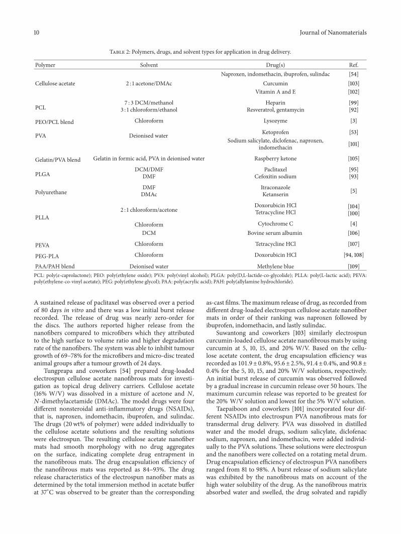
Table 2: Polymers, drugs, and solvent types for application in drug delivery.
Polymer Solvent Drug(s) Ref.Naproxen, indomethacin, ibuprofen, sulindac [54]
Cellulose acetate 2 : 1 acetone/DMAc Curcumin [103]Vitamin A and E [102]
PCL7 : 3 DCM/methanol
3 : 1 chloroform/ethanolHeparin
Resveratrol, gentamycin[99][92]
PEO/PCL blend Chloroform Lysozyme [3]
PVA Deionised water Ketoprofen [53]Sodium salicylate, diclofenac, naproxen,
indomethacin [101]
Gelatin/PVA blend Gelatin in formic acid, PVA in deionised water Raspberry ketone [105]
PLGADCM/DMF
DMFPaclitaxel
Cefoxitin sodium[95][93]
PolyurethaneDMFDMAc
ItraconazoleKetanserin [5]
PLLA2 : 1 chloroform/acetone
Doxorubicin HClTetracycline HCl
[104][100]
Chloroform Cytochrome C [4]DCM Bovine serum albumin [106]
PEVA Chloroform Tetracycline HCl [107]
PEG-PLA Chloroform Doxorubicin HCl [94, 108]
PAA/PAH blend Deionised water Methylene blue [109]PCL: poly(𝜀-caprolactone); PEO: poly(ethylene oxide); PVA: poly(vinyl alcohol); PLGA: poly(D,L-lactide-co-glycolide); PLLA: poly(L-lactic acid); PEVA:poly(ethylene-co-vinyl acetate); PEG: poly(ethylene glycol); PAA: poly(acrylic acid); PAH: poly(allylamine hydrochloride).
A sustained release of paclitaxel was observed over a periodof 80 days in vitro and there was a low initial burst releaserecorded. The release of drug was nearly zero-order forthe discs. The authors reported higher release from thenanofibers compared to microfibers which they attributedto the high surface to volume ratio and higher degradationrate of the nanofibers. The system was able to inhibit tumourgrowth of 69–78% for the microfibers and micro-disc treatedanimal groups after a tumour growth of 24 days.
Tungprapa and coworkers [54] prepared drug-loadedelectrospun cellulose acetate nanofibrous mats for investi-gation as topical drug delivery carriers. Cellulose acetate(16% W/V) was dissolved in a mixture of acetone and 𝑁,𝑁-dimethylacetamide (DMAc). The model drugs were fourdifferent nonsteroidal anti-inflammatory drugs (NSAIDs),that is, naproxen, indomethacin, ibuprofen, and sulindac.The drugs (20wt% of polymer) were added individually tothe cellulose acetate solutions and the resulting solutionswere electrospun. The resulting cellulose acetate nanofibermats had smooth morphology with no drug aggregateson the surface, indicating complete drug entrapment inthe nanofibrous mats. The drug encapsulation efficiency ofthe nanofibrous mats was reported as 84–93%. The drugrelease characteristics of the electrospun nanofiber mats asdetermined by the total immersion method in acetate bufferat 37∘C was observed to be greater than the corresponding
as-cast films.Themaximum release of drug, as recorded fromdifferent drug-loaded electrospun cellulose acetate nanofibermats in order of their ranking was naproxen followed byibuprofen, indomethacin, and lastly sulindac.
Suwantong and coworkers [103] similarly electrospuncurcumin-loaded cellulose acetate nanofibrousmats by usingcurcumin at 5, 10, 15, and 20% W/V. Based on the cellu-lose acetate content, the drug encapsulation efficiency wasrecorded as 101.9±0.8%, 95.6±2.5%, 91.4±0.4%, and 90.8±0.4% for the 5, 10, 15, and 20% W/V solutions, respectively.An initial burst release of curcumin was observed followedby a gradual increase in curcumin release over 50 hours. Themaximum curcumin release was reported to be greatest forthe 20% W/V solution and lowest for the 5% W/V solution.
Taepaiboon and coworkers [101] incorporated four dif-ferent NSAIDs into electrospun PVA nanofibrous mats fortransdermal drug delivery. PVA was dissolved in distilledwater and the model drugs, sodium salicylate, diclofenacsodium, naproxen, and indomethacin, were added individ-ually to the PVA solutions. These solutions were electrospunand the nanofibers were collected on a rotating metal drum.Drug encapsulation efficiency of electrospun PVA nanofibersranged from 81 to 98%. A burst release of sodium salicylatewas exhibited by the nanofibrous mats on account of thehigh water solubility of the drug. As the nanofibrous matrixabsorbed water and swelled, the drug solvated and rapidly
Journal of Nanomaterials 11
leached out of thematrix.The total percentage of drug releasefrom the nanofibrous mats at 24 hours was 98, 97, 76, and42% for naproxen, sodium salicylate, diclofenac sodium, andindomethacin, respectively. The same group of researchersfurther investigated the potential of electrospinning celluloseacetate solution loaded with vitamins A (all-trans retinolacid) and vitamin E (𝛼-tocopherol) [102]. Solutions were pre-pared by dissolving 17% W/V cellulose acetate and vitaminA or vitamin E in a mixture of acetone and DMAc andwere electrospun and nanofibers were investigated for in vitrodrug release characteristics. Drug encapsulation efficiency of82.9 ± 2.2% and 44.5 ± 1.1% was achieved for vitamins E andA, respectively, and a gradual increase in the rate of releasewas recorded for both the vitamins from the nanofibrousmatsin comparison to the burst release from comparative as-castfilms. Amaximum release of approximately 52% and 34%wasrecorded for vitamin E and vitamin A, respectively, and thiswas achieved after a time period of 24 hours and 6 hours,respectively.
Verreck and coworkers [5] investigated the possibil-ity of incorporating water soluble drugs into hydrophobicpolyurethane (PU) electrospun nanofibers for application intopical drug administration. Solutions were made by dissolv-ing PU and itraconazole in DMF as well as PU and ketanserinin DMAc. The release of itraconazole from electrospun PUnanofibers increased gradually over 20 hours and there wasno initial burst release. Ketanserin release was observed to befaster than itraconazole during the first 4 hours, after which,ketanserin released slowly over 24 hours.
Zeng and coworkers [104] investigated the influence ofthe compatibility between the polymer solution and drug onthe release kinetics of electrospun nanofiber formulations.Paclitaxel, doxorubicin HCl, and doxorubicin-base wereemployed as the model drugs. PLLA was dissolved in amixture of chloroform and acetone and the drugs were addedto the solutions separately. Paclitaxel and doxorubicin-baseshowed superior compatibility with PLLA and desirable sol-ubility in the chloroform/acetone co-solvent system that wasused, which resulted in optimum drug encapsulation. Theauthors observed inadequate encapsulation of doxorubicinHCl into the nanofiber matrix and the drug was confinednear or on the surface of the PLLA nanofibers. The releaserate of paclitaxel and doxorubicin-base was nearly zero-orderdue to nanofiber degradation whereas, a burst release ofdoxorubicin HCl was observed due to fast desorption fromthe nanofiber surface. It was concluded that drug solubilityand compatibility with solvents and polymers are importantfactors to be considered for adequate entrapment of drugmolecules in electrospun nanofiber matrices.
3.2.2. Effect of Solubilizing Drug Prior to the Addition of thePolymer Solution. Kenawy and coworkers [107] reported theapplicability of electrospun nanofiber mats as drug deliv-ery systems using poly(ethylene-co-vinyl acetate) (PEVA),poly(lactic acid) (PLA) and a 50 : 50 blend of the twopolymers. The polymers were individually dissolved in chlo-roform and tetracycline HCl, which was used as a modeldrug, and thereafter added to the polymer solutions.Thedrug
release rate as recorded from individual polymeric nanofibermats was highest for PEVA, releasing approximately 65%of drug followed by 50 : 50 PLA/PEVA blended nanofibermats that displayed a release of 50% drug content over aperiod of 5 days. PLA nanofiber mats exhibited an initialburst release effect arising from desorption of drug adheringto the surface of nanofibers followed by a negligible releaseover the next 50 hours. Authors compared the release profileof electrospun mats with corresponding films and reportedgreater release from the former which they explained on thebasis of higher surface to volume ratio of the electrospunmats.The same group of authors developed another system ofcontrolled drug release by electrospinning partially and fullyhydrolysed PVA from deionised water [53]. The drug, keto-profen dissolved in a small amount of methanol, was addedto the polymer solution. It was observed that fully hydrolysedPVA with entrapped ketoprofen could only be electrospunwhen combined with a small amount of surfactant (TritonX-100) and acetic acid. Additionally, authors stabilized thedrug embedded PVA matrix with methanol treatment whichresulted in crosslinking and eliminating the burst release ofthe drug from fibermatrix. Furthermore, methanol stabilizedmatrix exhibited a slow drug release over a period of twoweeks and also, the overall drug release was lower fromtreated fibers. Authors reported the degree of hydrolysis ofPVA to have additional effect on the drug release rate.
Kim and coworkers [93] investigated the release ofhydrophilic drug, cefoxitin sodium, from hydrophobicPLGA-based electrospun fibrous scaffolds. PLGA was dis-solved in DMF at 33% W/V. Cefoxitin sodium was dissolvedin a small amount of water and this aqueous drug solutionwas slowly added to the polymer solution and the obtaineddrug/polymer solution was electrospun. The drug concen-tration was found to influence the morphology and densityof the scaffolds. As the drug concentration increased, thescaffold density decreased and the fiber morphology changedfrom bead-and-string to fibers due to the salt effect duringelectrospinning. Adding amphiphilic poly(ethylene glycol)PEG-b-PLA block copolymer to the electrospinning solutionresulted in fiber scaffold exhibiting sustained release of thedrug up to one week. Addition of amphiphilic polymeraccounted for drug being embedded in the polymer matrixwhich was earlier located at the fiber surface due to lessphysical interaction with hydrophobic polymer and higherionic strength of hydrophilic drug. In another study, Kenawyand coworkers [53] examined the controlled release of aprotein drug from electrospun fiber meshes composed ofa blend of poly(𝜀-caprolactone) (PCL) and PEO. Lysozymewas employed as a model protein drug. A blend of PCL andPEO was dissolved in chloroform at varying ratios. Salt-freeand dried lysozyme was dissolved in dimethylsulphoxide andthe resulting solution was mixed with the polymer blendsolution. Protein release studies from electrospun polymericmeshwere carried out and itwas found that blends containinga large amount of PEO demonstrated a more rapid releaseof the model protein. Lysozyme release thus could readily becontrolled by varying the polymer blend ratio. In a study byLuong-Van and coworkers [99], heparin-loaded nanofibrousPCL mats were fabricated by electrospinning. Heparin was
12 Journal of Nanomaterials
dissolved in a small quantity of water and methanol wasadded. This solution was added to DCM and the resultingsolutionwas used to dissolve PCL.Thepolymer/drug solutionwas electrospun and the nanofibers were collected on glassmicroscope slides. The authors reported that heparin wasreleased from the nanofibrous mats in a sustained mannerover a period of 14 days.
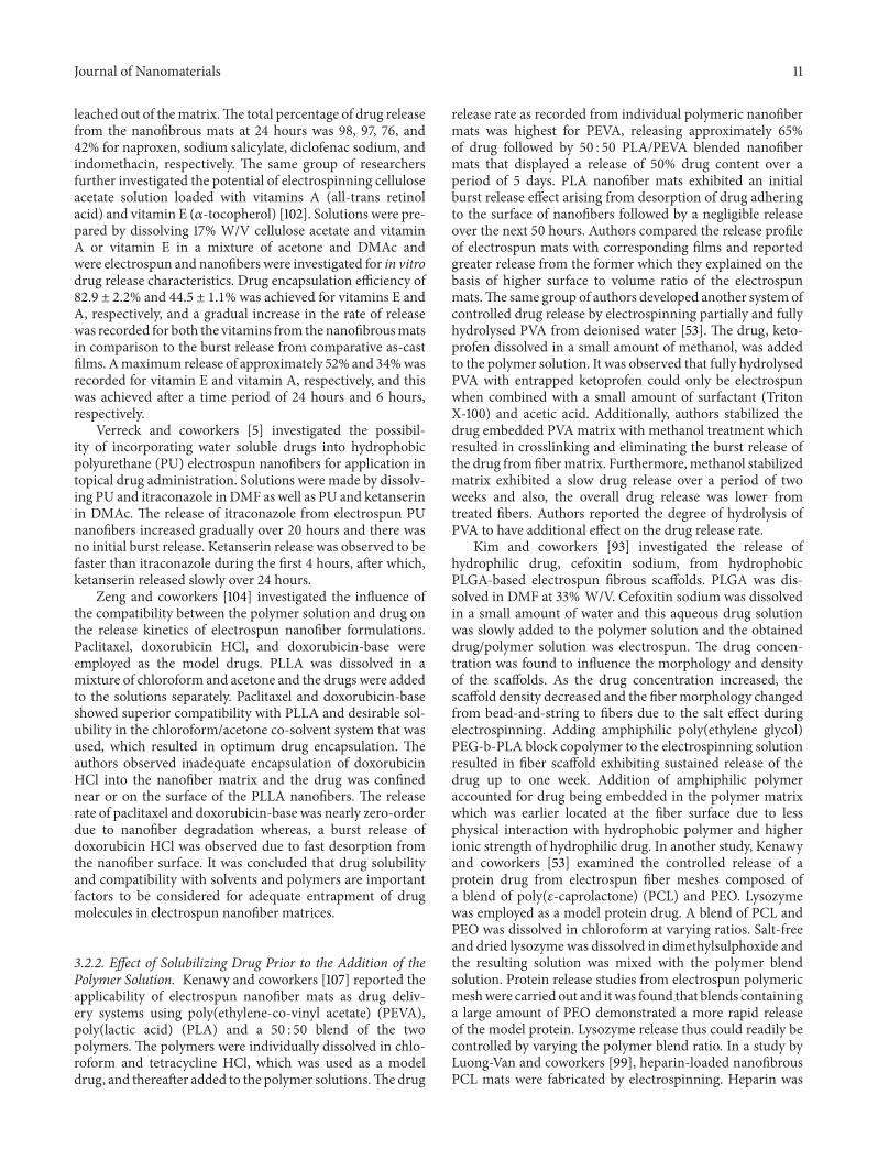
3.2.3. Coaxial Electrospinning. Coaxial electrospinningallows for electrospinning two different polymer solutions ora polymer solution and a drug reservoir in a single setupwhileloaded as separate entities in respective concentric capillaries.This mode of electrospinning form of core-shell nanofibersis especially useful in fabricating nanofibers that encapsulatethe drug within the core thereby minimizing initial burstrelease of the drug and shifting the release mechanismmainly to drug diffusion or nanofiber degradation ratherthan desorption from nanofiber surface. Drug-loading andrelease in such systems can be regulated by optimizingthe feed-rate of drug solution, higher feed-rates providehigher drug-loading and visa-versa. A schematic for coaxialelectrospinning apparatus is shown in Figure 5 [112].
Huang and coworkers [92] fabricated drug-loadeddouble-layered PCL nanofibers by coaxial electrospinning.PCL was dissolved in a mixture of chloroform and ethanoland the model drugs, resveratrol, and gentamycin sulphatewere dissolved in ethanol and water, respectively. Thepolymer concentration was kept constant and the drugconcentrations varied. The drug and polymer solutionswere fed through coaxial needles, with the drug solutionin the inner core needle and the polymer solution in theouter needle. A potential was applied and nanofibers, witha drug core and an outer polymer sheath, were collected ona grounded metal screen. It was found that when the drugand polymer solutions were miscible (resveratrol-loadednanofibers), an increase in drug concentration resulted ina decrease in bead defects, but when the drug and polymersolutions were immiscible (gentamycin sulphate loadednanofibers), the opposite was true. The drug release profileof PCL nanofibrous mat exhibited no burst release, instead aconsistent release was observed for both drugs over-seven-day a period. This release of encapsulated drug is attributedto the pace of PCL matrix degradation.
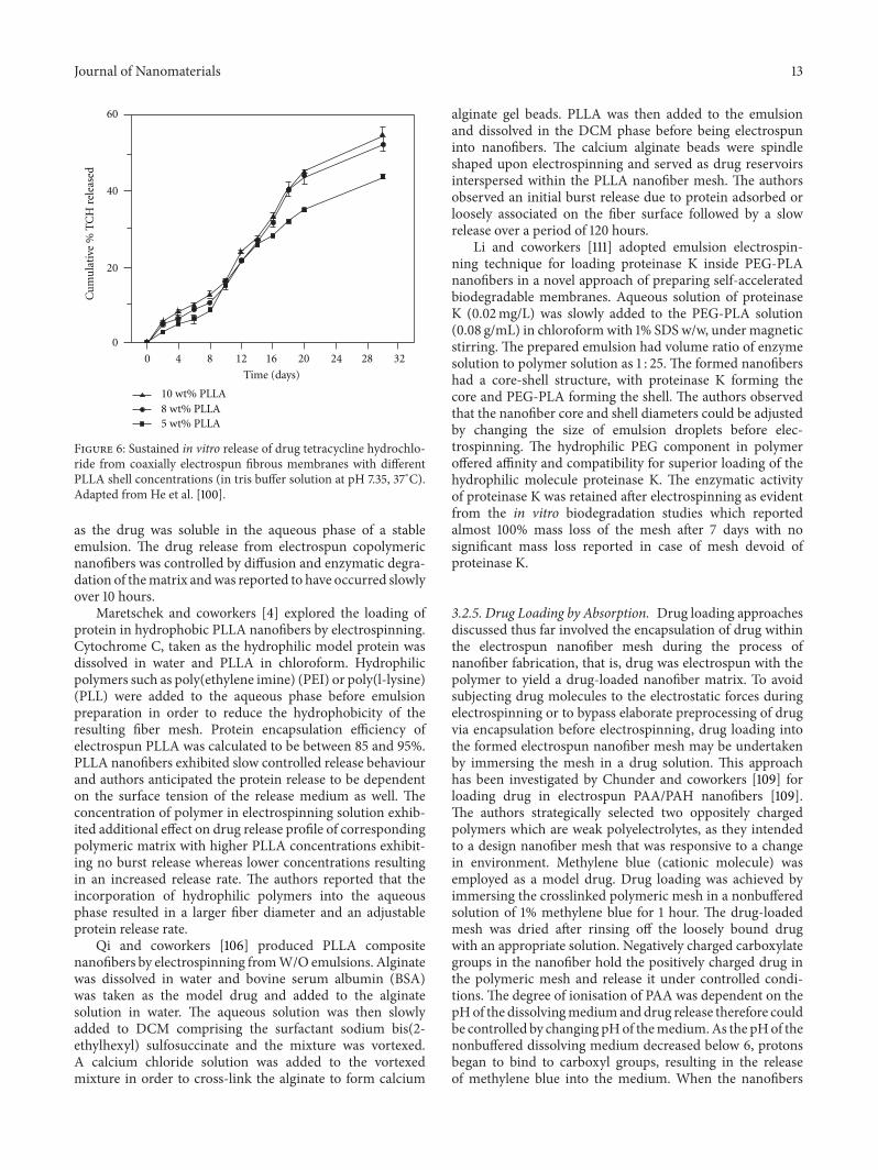
In a study by He and coworkers [100], drug-loaded core-shell nanofibers of PLLA were produced by coaxial electro-spinning. PLLAwas dissolved in amixture of chloroform andacetone and the model drug; tetracycline HCl was dissolvedin amixture ofmethanol and chloroformwith a small amountof PLLA. Triallyl isocyanurate was added to the polymersolution as a cross-linking agent. Drug concentration waskept constant while polymer concentration was varied. Thedrug solution was fed through the inner needle and thepolymer solution through the outer needle and the fiberscollected depicted sustained drug release over a periodof 32 days (Figure 6). The authors observed that a lowerpolymer concentration resulted in the formation ofmore uni-form nanofibers with narrow diameter distribution, whereas,higher polymer concentrations resulted in the formationof larger diameter nanofibers (Figure 7). The authors thus
Inner fluid
Solorpolymer
Figure 5: Schematic showing the coaxial electrospinning apparatussetup. Adapted from Jacoby [112].
inferred that drug release rate may be adjusted by changingthe polymer concentration and hence shell thickness.
Wang and coworkers [113] prepared biodegradable core-shell nanofibers by coaxial electrospinning of PDLLAand poly(3-hydroxybutyrate) (PHB) solution. They prepar-ed PDLLA/PHB or PHB/PDLLA core-shell nanofibers byreversing the polymer solutions in the inner and outer cap-illaries. Authors reported the flow-rate of core liquid to havepredominant effect on both outer and inner fiber diameter.The authors have extensively surveyed the effect of flow-rateon morphologies of the tailor cone, the polymer jet, andthe electrospun nanofibers. The two polymers PDLLA andPHB in fibrous mesh coexisted in amorphous and crystallinestate, respectively.The PDLLA/PHB nanofibers were used forthe delivery of the drug dimethyloxalylglycine (DMOG)—aproangiogenic compound—from the core section. The poly-meric nanofibers exhibited two-stage drug release kineticsin contrast to the burst release from electrospun nanofibersof either PDLLA of PHB alone. Nanofibers exhibited ∼25%drug release for the first stage (in 60 hours) followed by linearrelease that was controlled by the nanofiber thickness of thePHB shell of 70% of the drug.
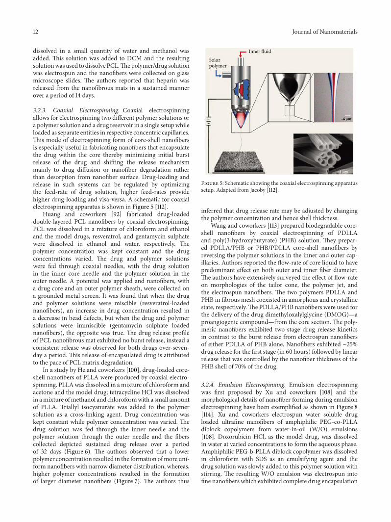
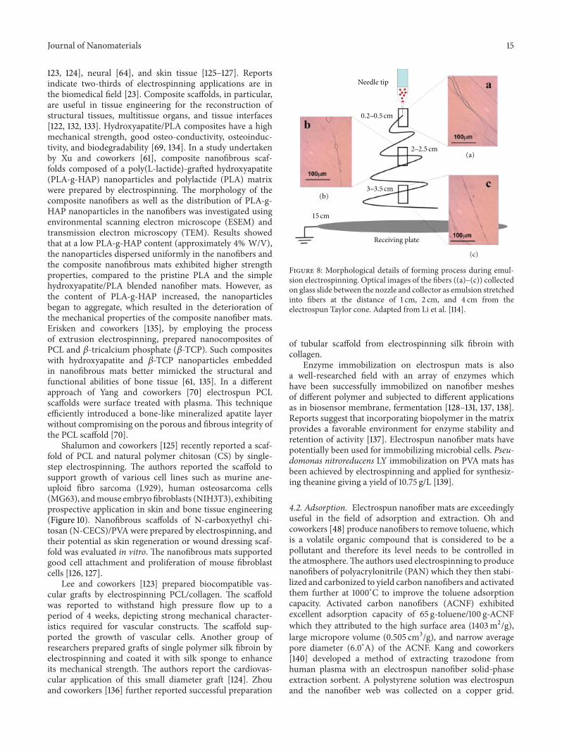
3.2.4. Emulsion Electrospinning. Emulsion electrospinningwas first proposed by Xu and coworkers [108] and themorphological details of nanofiber forming during emulsionelectrospinning have been exemplified as shown in Figure 8[114]. Xu and coworkers electrospun water soluble drugloaded ultrafine nanofibers of amphiphilic PEG-co-PLLAdiblock copolymers from water-in-oil (W/O) emulsions[108]. Doxorubicin HCl, as the model drug, was dissolvedin water at varied concentrations to form the aqueous phase.Amphiphilic PEG-b-PLLA diblock copolymer was dissolvedin chloroform with SDS as an emulsifying agent and thedrug solution was slowly added to this polymer solution withstirring. The resulting W/O emulsion was electrospun intofine nanofibers which exhibited complete drug encapsulation
Journal of Nanomaterials 13
0
20
40
60
Cu
mu
lati
ve %
TC
H r
elea
sed
0 4 8 12 16 20 24 28 32
Time (days)
10 wt% PLLA8 wt% PLLA5 wt% PLLA
Figure 6: Sustained in vitro release of drug tetracycline hydrochlo-ride from coaxially electrospun fibrous membranes with differentPLLA shell concentrations (in tris buffer solution at pH 7.35, 37∘C).Adapted from He et al. [100].
as the drug was soluble in the aqueous phase of a stableemulsion. The drug release from electrospun copolymericnanofibers was controlled by diffusion and enzymatic degra-dation of thematrix andwas reported to have occurred slowlyover 10 hours.
Maretschek and coworkers [4] explored the loading ofprotein in hydrophobic PLLA nanofibers by electrospinning.Cytochrome C, taken as the hydrophilic model protein wasdissolved in water and PLLA in chloroform. Hydrophilicpolymers such as poly(ethylene imine) (PEI) or poly(l-lysine)(PLL) were added to the aqueous phase before emulsionpreparation in order to reduce the hydrophobicity of theresulting fiber mesh. Protein encapsulation efficiency ofelectrospun PLLA was calculated to be between 85 and 95%.PLLA nanofibers exhibited slow controlled release behaviourand authors anticipated the protein release to be dependenton the surface tension of the release medium as well. Theconcentration of polymer in electrospinning solution exhib-ited additional effect on drug release profile of correspondingpolymeric matrix with higher PLLA concentrations exhibit-ing no burst release whereas lower concentrations resultingin an increased release rate. The authors reported that theincorporation of hydrophilic polymers into the aqueousphase resulted in a larger fiber diameter and an adjustableprotein release rate.
Qi and coworkers [106] produced PLLA compositenanofibers by electrospinning fromW/O emulsions. Alginatewas dissolved in water and bovine serum albumin (BSA)was taken as the model drug and added to the alginatesolution in water. The aqueous solution was then slowlyadded to DCM comprising the surfactant sodium bis(2-ethylhexyl) sulfosuccinate and the mixture was vortexed.A calcium chloride solution was added to the vortexedmixture in order to cross-link the alginate to form calcium
alginate gel beads. PLLA was then added to the emulsionand dissolved in the DCM phase before being electrospuninto nanofibers. The calcium alginate beads were spindleshaped upon electrospinning and served as drug reservoirsinterspersed within the PLLA nanofiber mesh. The authorsobserved an initial burst release due to protein adsorbed orloosely associated on the fiber surface followed by a slowrelease over a period of 120 hours.
Li and coworkers [111] adopted emulsion electrospin-ning technique for loading proteinase K inside PEG-PLAnanofibers in a novel approach of preparing self-acceleratedbiodegradable membranes. Aqueous solution of proteinaseK (0.02mg/L) was slowly added to the PEG-PLA solution(0.08 g/mL) in chloroformwith 1% SDS w/w, under magneticstirring. The prepared emulsion had volume ratio of enzymesolution to polymer solution as 1 : 25. The formed nanofibershad a core-shell structure, with proteinase K forming thecore and PEG-PLA forming the shell. The authors observedthat the nanofiber core and shell diameters could be adjustedby changing the size of emulsion droplets before elec-trospinning. The hydrophilic PEG component in polymeroffered affinity and compatibility for superior loading of thehydrophilic molecule proteinase K. The enzymatic activityof proteinase K was retained after electrospinning as evidentfrom the in vitro biodegradation studies which reportedalmost 100% mass loss of the mesh after 7 days with nosignificant mass loss reported in case of mesh devoid ofproteinase K.
3.2.5. Drug Loading by Absorption. Drug loading approachesdiscussed thus far involved the encapsulation of drug withinthe electrospun nanofiber mesh during the process ofnanofiber fabrication, that is, drug was electrospun with thepolymer to yield a drug-loaded nanofiber matrix. To avoidsubjecting drug molecules to the electrostatic forces duringelectrospinning or to bypass elaborate preprocessing of drugvia encapsulation before electrospinning, drug loading intothe formed electrospun nanofiber mesh may be undertakenby immersing the mesh in a drug solution. This approachhas been investigated by Chunder and coworkers [109] forloading drug in electrospun PAA/PAH nanofibers [109].The authors strategically selected two oppositely chargedpolymers which are weak polyelectrolytes, as they intendedto a design nanofiber mesh that was responsive to a changein environment. Methylene blue (cationic molecule) wasemployed as a model drug. Drug loading was achieved byimmersing the crosslinked polymeric mesh in a nonbufferedsolution of 1% methylene blue for 1 hour. The drug-loadedmesh was dried after rinsing off the loosely bound drugwith an appropriate solution. Negatively charged carboxylategroups in the nanofiber hold the positively charged drug inthe polymeric mesh and release it under controlled condi-tions. The degree of ionisation of PAA was dependent on thepHof the dissolvingmediumanddrug release therefore couldbe controlled by changing pHof themedium.As the pHof thenonbuffered dissolving medium decreased below 6, protonsbegan to bind to carboxyl groups, resulting in the releaseof methylene blue into the medium. When the nanofibers
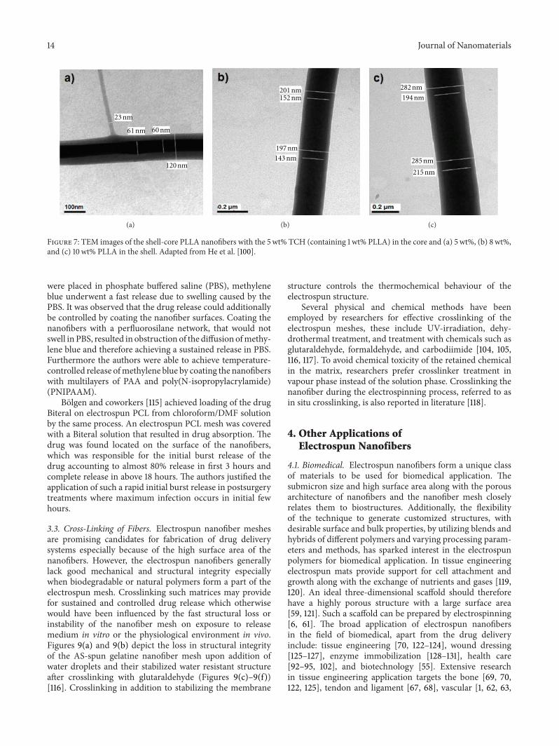
14 Journal of Nanomaterials
120 nm
23 nm
61 nm 60 nm
(a)
201 nm152 nm
197 nm
143 nm
(b)
282 nm
285 nm
215 nm
194 nm
(c)
Figure 7: TEM images of the shell-core PLLA nanofibers with the 5wt% TCH (containing 1 wt% PLLA) in the core and (a) 5 wt%, (b) 8wt%,and (c) 10wt% PLLA in the shell. Adapted from He et al. [100].
were placed in phosphate buffered saline (PBS), methyleneblue underwent a fast release due to swelling caused by thePBS. It was observed that the drug release could additionallybe controlled by coating the nanofiber surfaces. Coating thenanofibers with a perfluorosilane network, that would notswell in PBS, resulted in obstruction of the diffusion ofmethy-lene blue and therefore achieving a sustained release in PBS.Furthermore the authors were able to achieve temperature-controlled release ofmethylene blue by coating the nanofiberswith multilayers of PAA and poly(N-isopropylacrylamide)(PNIPAAM).
Bolgen and coworkers [115] achieved loading of the drugBiteral on electrospun PCL from chloroform/DMF solutionby the same process. An electrospun PCL mesh was coveredwith a Biteral solution that resulted in drug absorption. Thedrug was found located on the surface of the nanofibers,which was responsible for the initial burst release of thedrug accounting to almost 80% release in first 3 hours andcomplete release in above 18 hours. The authors justified theapplication of such a rapid initial burst release in postsurgerytreatments where maximum infection occurs in initial fewhours.
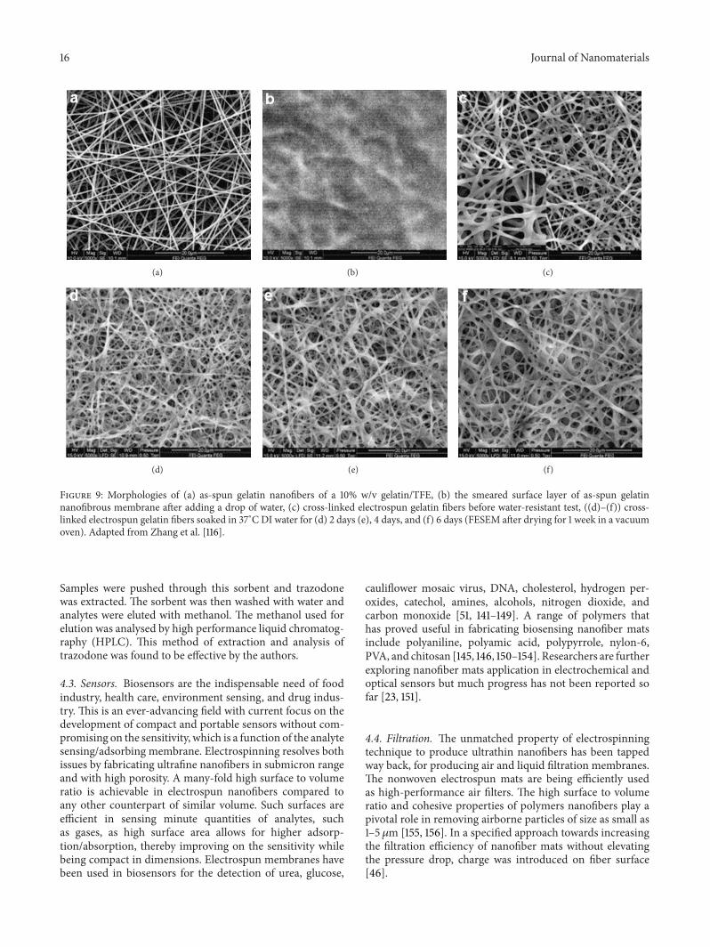
3.3. Cross-Linking of Fibers. Electrospun nanofiber meshesare promising candidates for fabrication of drug deliverysystems especially because of the high surface area of thenanofibers. However, the electrospun nanofibers generallylack good mechanical and structural integrity especiallywhen biodegradable or natural polymers form a part of theelectrospun mesh. Crosslinking such matrices may providefor sustained and controlled drug release which otherwisewould have been influenced by the fast structural loss orinstability of the nanofiber mesh on exposure to releasemedium in vitro or the physiological environment in vivo.Figures 9(a) and 9(b) depict the loss in structural integrityof the AS-spun gelatine nanofiber mesh upon addition ofwater droplets and their stabilized water resistant structureafter crosslinking with glutaraldehyde (Figures 9(c)–9(f))[116]. Crosslinking in addition to stabilizing the membrane
structure controls the thermochemical behaviour of theelectrospun structure.
Several physical and chemical methods have beenemployed by researchers for effective crosslinking of theelectrospun meshes, these include UV-irradiation, dehy-drothermal treatment, and treatment with chemicals such asglutaraldehyde, formaldehyde, and carbodiimide [104, 105,116, 117]. To avoid chemical toxicity of the retained chemicalin the matrix, researchers prefer crosslinker treatment invapour phase instead of the solution phase. Crosslinking thenanofiber during the electrospinning process, referred to asin situ crosslinking, is also reported in literature [118].
4. Other Applications ofElectrospun Nanofibers
4.1. Biomedical. Electrospun nanofibers form a unique classof materials to be used for biomedical application. Thesubmicron size and high surface area along with the porousarchitecture of nanofibers and the nanofiber mesh closelyrelates them to biostructures. Additionally, the flexibilityof the technique to generate customized structures, withdesirable surface and bulk properties, by utilizing blends andhybrids of different polymers and varying processing param-eters and methods, has sparked interest in the electrospunpolymers for biomedical application. In tissue engineeringelectrospun mats provide support for cell attachment andgrowth along with the exchange of nutrients and gases [119,120]. An ideal three-dimensional scaffold should thereforehave a highly porous structure with a large surface area[59, 121]. Such a scaffold can be prepared by electrospinning[6, 61]. The broad application of electrospun nanofibersin the field of biomedical, apart from the drug deliveryinclude: tissue engineering [70, 122–124], wound dressing[125–127], enzyme immobilization [128–131], health care[92–95, 102], and biotechnology [55]. Extensive researchin tissue engineering application targets the bone [69, 70,122, 125], tendon and ligament [67, 68], vascular [1, 62, 63,
Journal of Nanomaterials 15
123, 124], neural [64], and skin tissue [125–127]. Reportsindicate two-thirds of electrospinning applications are inthe biomedical field [23]. Composite scaffolds, in particular,are useful in tissue engineering for the reconstruction ofstructural tissues, multitissue organs, and tissue interfaces[122, 132, 133]. Hydroxyapatite/PLA composites have a highmechanical strength, good osteo-conductivity, osteoinduc-tivity, and biodegradability [69, 134]. In a study undertakenby Xu and coworkers [61], composite nanofibrous scaf-folds composed of a poly(L-lactide)-grafted hydroxyapatite(PLA-g-HAP) nanoparticles and polylactide (PLA) matrixwere prepared by electrospinning. The morphology of thecomposite nanofibers as well as the distribution of PLA-g-HAP nanoparticles in the nanofibers was investigated usingenvironmental scanning electron microscope (ESEM) andtransmission electron microscopy (TEM). Results showedthat at a low PLA-g-HAP content (approximately 4% W/V),the nanoparticles dispersed uniformly in the nanofibers andthe composite nanofibrous mats exhibited higher strengthproperties, compared to the pristine PLA and the simplehydroxyapatite/PLA blended nanofiber mats. However, asthe content of PLA-g-HAP increased, the nanoparticlesbegan to aggregate, which resulted in the deterioration ofthe mechanical properties of the composite nanofiber mats.Erisken and coworkers [135], by employing the processof extrusion electrospinning, prepared nanocomposites ofPCL and 𝛽-tricalcium phosphate (𝛽-TCP). Such compositeswith hydroxyapatite and 𝛽-TCP nanoparticles embeddedin nanofibrous mats better mimicked the structural andfunctional abilities of bone tissue [61, 135]. In a differentapproach of Yang and coworkers [70] electrospun PCLscaffolds were surface treated with plasma. This techniqueefficiently introduced a bone-like mineralized apatite layerwithout compromising on the porous and fibrous integrity ofthe PCL scaffold [70].
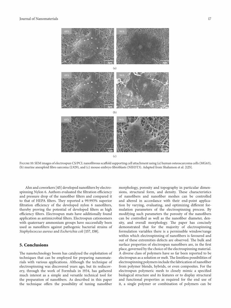
Shalumon and coworkers [125] recently reported a scaf-fold of PCL and natural polymer chitosan (CS) by single-step electrospinning. The authors reported the scaffold tosupport growth of various cell lines such as murine ane-uploid fibro sarcoma (L929), human osteosarcoma cells(MG63), andmouse embryo fibroblasts (NIH3T3), exhibitingprospective application in skin and bone tissue engineering(Figure 10). Nanofibrous scaffolds of N-carboxyethyl chi-tosan (N-CECS)/PVA were prepared by electrospinning, andtheir potential as skin regeneration or wound dressing scaf-fold was evaluated in vitro. The nanofibrous mats supportedgood cell attachment and proliferation of mouse fibroblastcells [126, 127].
Lee and coworkers [123] prepared biocompatible vas-cular grafts by electrospinning PCL/collagen. The scaffoldwas reported to withstand high pressure flow up to aperiod of 4 weeks, depicting strong mechanical character-istics required for vascular constructs. The scaffold sup-ported the growth of vascular cells. Another group ofresearchers prepared grafts of single polymer silk fibroin byelectrospinning and coated it with silk sponge to enhanceits mechanical strength. The authors report the cardiovas-cular application of this small diameter graft [124]. Zhouand coworkers [136] further reported successful preparation
Receiving plate
15 cm
0.2–0.5 cm
2–2.5 cm
Needle tip
3–3.5 cm
(a)
(b)
(c)
Figure 8: Morphological details of forming process during emul-sion electrospinning. Optical images of the fibers ((a)–(c)) collectedon glass slide between the nozzle and collector as emulsion stretchedinto fibers at the distance of 1 cm, 2 cm, and 4 cm from theelectrospun Taylor cone. Adapted from Li et al. [114].
of tubular scaffold from electrospinning silk fibroin withcollagen.
Enzyme immobilization on electrospun mats is alsoa well-researched field with an array of enzymes whichhave been successfully immobilized on nanofiber meshesof different polymer and subjected to different applicationsas in biosensor membrane, fermentation [128–131, 137, 138].Reports suggest that incorporating biopolymer in the matrixprovides a favorable environment for enzyme stability andretention of activity [137]. Electrospun nanofiber mats havepotentially been used for immobilizing microbial cells. Pseu-domonas nitroreducens LY immobilization on PVA mats hasbeen achieved by electrospinning and applied for synthesiz-ing theanine giving a yield of 10.75 g/L [139].
4.2. Adsorption. Electrospun nanofiber mats are exceedinglyuseful in the field of adsorption and extraction. Oh andcoworkers [48] produce nanofibers to remove toluene, whichis a volatile organic compound that is considered to be apollutant and therefore its level needs to be controlled inthe atmosphere.The authors used electrospinning to producenanofibers of polyacrylonitrile (PAN) which they then stabi-lized and carbonized to yield carbon nanofibers and activatedthem further at 1000∘C to improve the toluene adsorptioncapacity. Activated carbon nanofibers (ACNF) exhibitedexcellent adsorption capacity of 65 g-toluene/100 g-ACNFwhich they attributed to the high surface area (1403m2/g),large micropore volume (0.505 cm3/g), and narrow averagepore diameter (6.0∘A) of the ACNF. Kang and coworkers[140] developed a method of extracting trazodone fromhuman plasma with an electrospun nanofiber solid-phaseextraction sorbent. A polystyrene solution was electrospunand the nanofiber web was collected on a copper grid.
16 Journal of Nanomaterials
(a) (b) (c)
(d) (e) (f)
Figure 9: Morphologies of (a) as-spun gelatin nanofibers of a 10% w/v gelatin/TFE, (b) the smeared surface layer of as-spun gelatinnanofibrous membrane after adding a drop of water, (c) cross-linked electrospun gelatin fibers before water-resistant test, ((d)–(f)) cross-linked electrospun gelatin fibers soaked in 37∘CDI water for (d) 2 days (e), 4 days, and (f) 6 days (FESEM after drying for 1 week in a vacuumoven). Adapted from Zhang et al. [116].
Samples were pushed through this sorbent and trazodonewas extracted. The sorbent was then washed with water andanalytes were eluted with methanol. The methanol used forelution was analysed by high performance liquid chromatog-raphy (HPLC). This method of extraction and analysis oftrazodone was found to be effective by the authors.
4.3. Sensors. Biosensors are the indispensable need of foodindustry, health care, environment sensing, and drug indus-try. This is an ever-advancing field with current focus on thedevelopment of compact and portable sensors without com-promising on the sensitivity, which is a function of the analytesensing/adsorbing membrane. Electrospinning resolves bothissues by fabricating ultrafine nanofibers in submicron rangeand with high porosity. A many-fold high surface to volumeratio is achievable in electrospun nanofibers compared toany other counterpart of similar volume. Such surfaces areefficient in sensing minute quantities of analytes, suchas gases, as high surface area allows for higher adsorp-tion/absorption, thereby improving on the sensitivity whilebeing compact in dimensions. Electrospun membranes havebeen used in biosensors for the detection of urea, glucose,
cauliflower mosaic virus, DNA, cholesterol, hydrogen per-oxides, catechol, amines, alcohols, nitrogen dioxide, andcarbon monoxide [51, 141–149]. A range of polymers thathas proved useful in fabricating biosensing nanofiber matsinclude polyaniline, polyamic acid, polypyrrole, nylon-6,PVA, and chitosan [145, 146, 150–154]. Researchers are furtherexploring nanofiber mats application in electrochemical andoptical sensors but much progress has not been reported sofar [23, 151].
4.4. Filtration. The unmatched property of electrospinningtechnique to produce ultrathin nanofibers has been tappedway back, for producing air and liquid filtration membranes.The nonwoven electrospun mats are being efficiently usedas high-performance air filters. The high surface to volumeratio and cohesive properties of polymers nanofibers play apivotal role in removing airborne particles of size as small as1–5 𝜇m [155, 156]. In a specified approach towards increasingthe filtration efficiency of nanofiber mats without elevatingthe pressure drop, charge was introduced on fiber surface[46].
Journal of Nanomaterials 17
48 h 96 h
(a)
48 h 96 h
(b)
96 h48 h
(c)
Figure 10: SEM images of electrospunCS/PCL nanofibrous scaffold supporting cell attachment using (a) human osteoscarcoma cells (MG63),(b) murine aneuploid fibro sarcoma (L929), and (c) mouse embryo fibroblasts (NIH3T3). Adapted from Shalumon et al. [125].
Ahn and coworkers [45] developed nanofilters by electro-spinning Nylon 6. Authors evaluated the filtration efficiencyand pressure drop of the nanofiber filters and compared itto that of HEPA filters. They reported a 99.993% superiorfiltration efficiency of the developed nylon 6 nanofilters,thereby proving the potential of developed filters as highefficiency filters. Electrospun mats have additionally foundapplication as antimicrobial filters. Electrospun cationomerswith quaternary ammonium groups have successfully beenused as nanofilters against pathogenic bacterial strains ofStaphylococcus aureus and Escherichia coli [157, 158].
5. Conclusions
The nanotechnology boom has catalyzed the exploitation oftechniques that can be employed for preparing nanomate-rials with various applications. Although the technique ofelectrospinning was discovered years ago, but its rediscov-ery, through the work of Formhals in 1934, has gatheredmuch interest as a simple and versatile technical tool forthe preparation of nanofibers. As described in this paperthe technique offers the possibility of tuning nanofiber
morphology, porosity and topography in particular dimen-sions, structural form, and density. These characteristicsof nanofibers and nanofiber meshes can be controlledand altered in accordance with their end-point applica-tion by varying, evaluating, and optimizing different for-mulation parameters of the electrospinning process. Bymodifying such parameters the porosity of the nanofiberscan be controlled as well as the nanofiber diameter, den-sity, and overall morphology. The paper has conciselydemonstrated that for the majority of electrospinningformulation variables there is a permissible window/rangewithin which electrospinning of nanofibers is favoured andout of these extremities defects are observed. The bulk andsurface properties of electrospun nanofibers are, in the firstplace, governed by the choice of the electrospinningmaterial.A diverse class of polymers have so far been reported to beelectrospun as a solution or melt.The limitless possibilities ofelectrospinning polymers include the fabrication of nanofiberfrom polymer blends, hybrids, or even composites. For theelectrospun polymeric mesh to closely mimic a specifiedbiological structure and its features or to display structuraland functional properties as required for the end use ofit, a single polymer or combination of polymers can be
18 Journal of Nanomaterials
electrospun. Such versatility of the properties of electrospunnanofiber structures opens up plethora of diverse fields fortheir application, such as in drug delivery, tissue engineering,wound dressing, filtration, enzyme immobilization, and evenas sensors. Although new drug delivery systems based onelectrospinning are being formulated, there is still scope formuch extensive research on different electrospinning param-eters and to develop techniques for electrospinning newpolymer combinations. Novel methods for loading a varietyof drugs and other bioactivities in electrospun nanofibersneed to be exploited further to fulfil the growing demand ofthe need for drug delivery systems.
Conflict of Interests
The authors have no conflict of interests.
References
[1] Z.Ma,M. Kotaki, T. Yong,W. He, and S. Ramakrishna, “Surfaceengineering of electrospun polyethylene terephthalate (PET)nanofibers towards development of a new material for bloodvessel engineering,” Biomaterials, vol. 26, no. 15, pp. 2527–2536,2005.
[2] J. P. Chen, G. Y. Chang, and J. K. Chen, “Electrospun col-lagen/chitosan nanofibrous membrane as wound dressing,”Colloids and Surfaces A, vol. 313-314, pp. 183–188, 2008.
[3] T. G. Kim, D. S. Lee, and T. G. Park, “Controlled proteinrelease from electrospun biodegradable fiber mesh composedof poly(𝜀-caprolactone) and poly(ethylene oxide),” InternationalJournal of Pharmaceutics, vol. 338, no. 1-2, pp. 276–283, 2007.
[4] S. Maretschek, A. Greiner, and T. Kissel, “Electrospunbiodegradable nanofiber nonwovens for controlled releaseof proteins,” Journal of Controlled Release, vol. 127, no. 2, pp.180–187, 2008.
[5] G. Verreck, I. Chun, J. Rosenblatt et al., “Incorporation of drugsin an amorphous state into electrospun nanofibers composedof a water-insoluble, nonbiodegradable polymer,” Journal ofControlled Release, vol. 92, no. 3, pp. 349–360, 2003.
[6] X. L. Deng, G. Sui, M. L. Zhao, G. Q. Chen, and X. P.Yang, “Poly(L-lactic acid)/hydroxyapatite hybrid nanofibrousscaffolds prepared by electrospinning,” Journal of BiomaterialsScience, vol. 18, no. 1, pp. 117–130, 2007.
[7] P. X. Ma and R. Zhang, “Synthetic nano-scale fibrous extracel-lular matrix,” Journal of Biomedical Materials Research, vol. 46,no. 1, pp. 60–72, 1999.
[8] D. Liu, H. Zhang, P. C. M. Grim et al., “Self-assembly ofpolyphenylene dendrimers intomicrometer long nanofibers: anatomic force microscopy study,” Langmuir, vol. 18, no. 6, pp.2385–2391, 2002.
[9] G. Liu, L. Qiao, and A. Guo, “Diblock copolymer nanofibers,”Macromolecules, vol. 29, no. 16, pp. 5508–5510, 1996.
[10] X. Yan, G. Liu, F. Liu et al., “Superparamagnetic triblockcopolymer/Fe
2
O3
hybrid nanofibers,” Angewandte ChemieInternational Edition, vol. 40, no. 19, pp. 3593–3596, 2001.
[11] C.-G. Wu and T. Bein, “Conducting polyaniline filaments in amesoporous channel host,” Science, vol. 264, no. 5166, pp. 1757–1759, 1994.
[12] L. Feng, S. Li, H. Li et al., “Super-hydrophobic surface of alignedpolyacrylonitrile nanofibers,”Angewandte Chemie InternationalEdition, vol. 41, no. 7, pp. 1221–1223, 2002.
[13] T.Ondarcuhu andC. Joachim, “Drawing a single nanofiber overhundreds ofmicrons,”Europhysics Letters, vol. 42, no. 2, pp. 215–220, 1998.
[14] P. K. Baumgarten, “Electrostatic spinning of acrylic micro-fibers,” Journal of Colloid and Interface Science, vol. 36, no. 1, pp.71–79, 1971.
[15] J. Doshi and D. H. Reneker, “Electrospinning process andapplications of electrospun fibers,” Journal of Electrostatics, vol.35, no. 2-3, pp. 151–160, 1995.
[16] G. Taylor, “Electrically driven jets,” Proceedings of the RoyalSociety of London A, vol. 313, no. 1515, pp. 453–475, 1969.
[17] D. Liang, B. S. Hsiao, and B. Chu, “Functional electrospunnanofibrous scaffolds for biomedical applications,” AdvancedDrug Delivery Reviews, vol. 59, no. 14, pp. 1392–1412, 2007.
[18] G. G. Wallace, M. J. Higgins, S. E. Moulton, and C. Wang,“Nanobionics: the impact of nanotechnology on implantablemedical bionic devices,”Nanoscale, vol. 4, no. 15, pp. 4327–4347,2012.
[19] D. H. Reneker and I. Chun, “Nanometre diameter fibres ofpolymer, produced by electro-spinning,” Nanotechnology, vol.7, no. 3, pp. 216–223, 1996.
[20] D. Li and Y. Xia, “Electrospinning of nanofibers: reinventing thewheel?” Advanced Materials, vol. 16, no. 14, pp. 1151–1170, 2004.
[21] M. M. Hohman, M. Shin, G. Rutledge, and M. P. Brenner,“Electrospinning and electrically forced jets. I. Stability theory,”Physics of Fluids, vol. 13, no. 8, pp. 2201–2220, 2001.
[22] J. M. Deitzel, J. Kleinmeyer, D. Harris, and N. C. Beck Tan, “Theeffect of processing variables on the morphology of electrospunnanofibers and textiles,” Polymer, vol. 42, no. 1, pp. 261–272,2001.
[23] N. Bhardwaj and S. C. Kundu, “Electrospinning: a fascinatingfiber fabrication technique,”Biotechnology Advances, vol. 28, no.3, pp. 325–347, 2010.
[24] J. Zeleny, “The electrical discharge from liquid points, and ahydrostatic method of measuring the electric intensity at theirsurfaces,” Physical Review, vol. 3, no. 2, pp. 69–91, 1914.
[25] J. Zeleny, “Instability of electrified liquid surfaces,” PhysicalReview, vol. 10, no. 1, pp. 1–6, 1917.
[26] J. Zeleny, “The role of surface instability in electrical dischargesfrom drops of alcohol and water in air at atmospheric pressure,”Journal of the Franklin Institute, vol. 219, no. 6, pp. 659–675, 1935.
[27] A. Formhals, “Process and apparatus for preparing artificialthreads,” US Patent 1-975-504, 1934.
[28] A. Formhals, “Method and apparatus for spinning,” US Patent2-160-962, 1939.
[29] A. Formhals, “Artificial thread andmethod of producing same,”US Patent 2-187-306, 1940.
[30] A. Formhals, “Production of artificial fibres from fibre formingliquids,” US Patent 2-323-025, 1934.
[31] L. Larrondo and R. S. J. Manley, “Electrostatic fiber spinningfrom polymer melts. 1. Experimental-observations on fiberformation and properties,” Journal of Polymer Science A, vol. 19,no. 6, pp. 909–920, 1981.
[32] L. Larrondo and R. S. J. Manley, “Electrostatic fiber spinningfrom polymer melts. 2. Examination of the flow field in anelectrically driven jet,” Journal of Polymer Science A, vol. 19, no.6, pp. 921–932, 1981.
[33] W.Yao, J. Yang, J.Wang, andL. Tao, “Synthesis and electrochem-ical performance of carbon nanofiber-cobalt oxide composites,”Electrochimica Acta, vol. 53, no. 24, pp. 7326–7330, 2008.
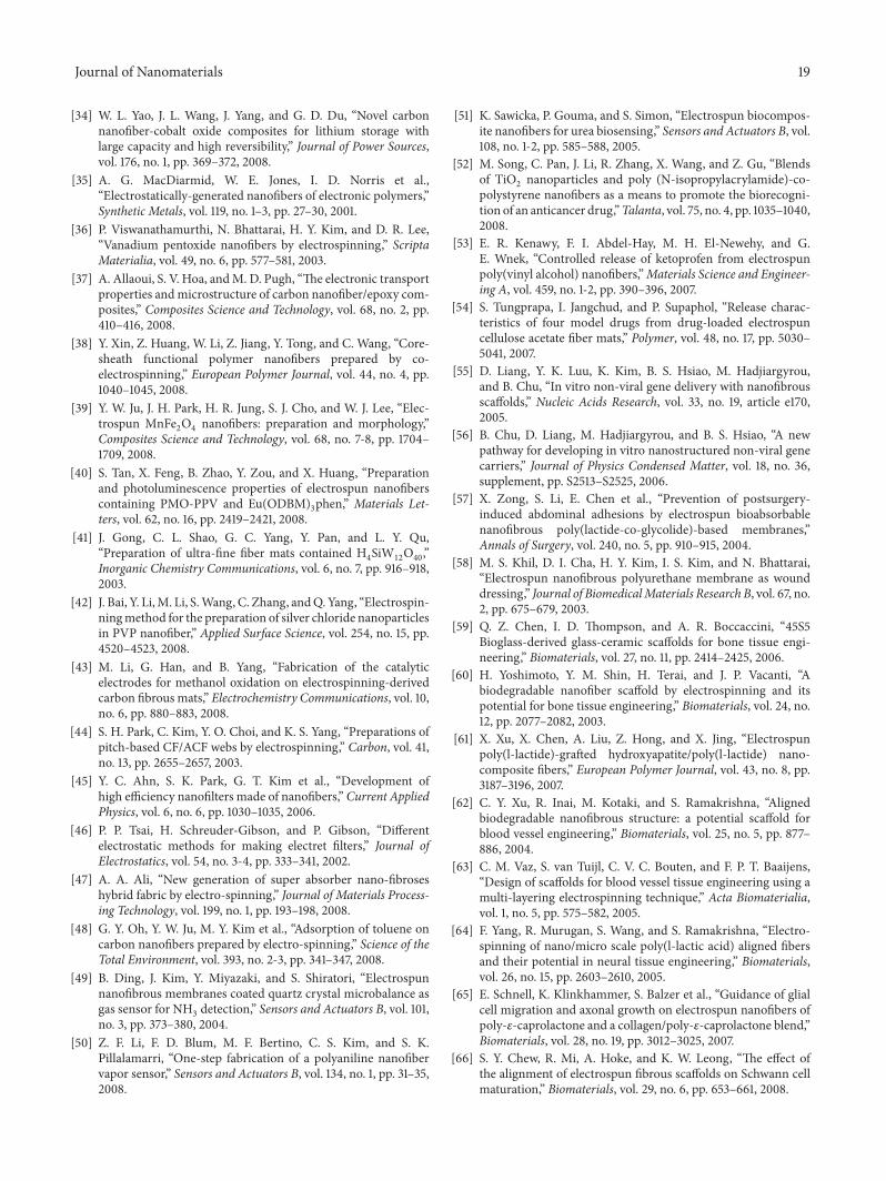
Journal of Nanomaterials 19
[34] W. L. Yao, J. L. Wang, J. Yang, and G. D. Du, “Novel carbonnanofiber-cobalt oxide composites for lithium storage withlarge capacity and high reversibility,” Journal of Power Sources,vol. 176, no. 1, pp. 369–372, 2008.
[35] A. G. MacDiarmid, W. E. Jones, I. D. Norris et al.,“Electrostatically-generated nanofibers of electronic polymers,”Synthetic Metals, vol. 119, no. 1–3, pp. 27–30, 2001.
[36] P. Viswanathamurthi, N. Bhattarai, H. Y. Kim, and D. R. Lee,“Vanadium pentoxide nanofibers by electrospinning,” ScriptaMaterialia, vol. 49, no. 6, pp. 577–581, 2003.
[37] A. Allaoui, S. V. Hoa, andM. D. Pugh, “The electronic transportproperties andmicrostructure of carbon nanofiber/epoxy com-posites,” Composites Science and Technology, vol. 68, no. 2, pp.410–416, 2008.
[38] Y. Xin, Z. Huang, W. Li, Z. Jiang, Y. Tong, and C. Wang, “Core-sheath functional polymer nanofibers prepared by co-electrospinning,” European Polymer Journal, vol. 44, no. 4, pp.1040–1045, 2008.
[39] Y. W. Ju, J. H. Park, H. R. Jung, S. J. Cho, and W. J. Lee, “Elec-trospun MnFe
2
O4
nanofibers: preparation and morphology,”Composites Science and Technology, vol. 68, no. 7-8, pp. 1704–1709, 2008.
[40] S. Tan, X. Feng, B. Zhao, Y. Zou, and X. Huang, “Preparationand photoluminescence properties of electrospun nanofiberscontaining PMO-PPV and Eu(ODBM)
3
phen,” Materials Let-ters, vol. 62, no. 16, pp. 2419–2421, 2008.
[41] J. Gong, C. L. Shao, G. C. Yang, Y. Pan, and L. Y. Qu,“Preparation of ultra-fine fiber mats contained H
4
SiW12
O40
,”Inorganic Chemistry Communications, vol. 6, no. 7, pp. 916–918,2003.
[42] J. Bai, Y. Li,M. Li, S.Wang, C. Zhang, andQ. Yang, “Electrospin-ningmethod for the preparation of silver chloride nanoparticlesin PVP nanofiber,” Applied Surface Science, vol. 254, no. 15, pp.4520–4523, 2008.
[43] M. Li, G. Han, and B. Yang, “Fabrication of the catalyticelectrodes for methanol oxidation on electrospinning-derivedcarbon fibrous mats,” Electrochemistry Communications, vol. 10,no. 6, pp. 880–883, 2008.
[44] S. H. Park, C. Kim, Y. O. Choi, and K. S. Yang, “Preparations ofpitch-based CF/ACF webs by electrospinning,” Carbon, vol. 41,no. 13, pp. 2655–2657, 2003.
[45] Y. C. Ahn, S. K. Park, G. T. Kim et al., “Development ofhigh efficiency nanofilters made of nanofibers,” Current AppliedPhysics, vol. 6, no. 6, pp. 1030–1035, 2006.
[46] P. P. Tsai, H. Schreuder-Gibson, and P. Gibson, “Differentelectrostatic methods for making electret filters,” Journal ofElectrostatics, vol. 54, no. 3-4, pp. 333–341, 2002.
[47] A. A. Ali, “New generation of super absorber nano-fibroseshybrid fabric by electro-spinning,” Journal of Materials Process-ing Technology, vol. 199, no. 1, pp. 193–198, 2008.
[48] G. Y. Oh, Y. W. Ju, M. Y. Kim et al., “Adsorption of toluene oncarbon nanofibers prepared by electro-spinning,” Science of theTotal Environment, vol. 393, no. 2-3, pp. 341–347, 2008.
[49] B. Ding, J. Kim, Y. Miyazaki, and S. Shiratori, “Electrospunnanofibrous membranes coated quartz crystal microbalance asgas sensor for NH
3
detection,” Sensors and Actuators B, vol. 101,no. 3, pp. 373–380, 2004.
[50] Z. F. Li, F. D. Blum, M. F. Bertino, C. S. Kim, and S. K.Pillalamarri, “One-step fabrication of a polyaniline nanofibervapor sensor,” Sensors and Actuators B, vol. 134, no. 1, pp. 31–35,2008.
[51] K. Sawicka, P. Gouma, and S. Simon, “Electrospun biocompos-ite nanofibers for urea biosensing,” Sensors and Actuators B, vol.108, no. 1-2, pp. 585–588, 2005.
[52] M. Song, C. Pan, J. Li, R. Zhang, X. Wang, and Z. Gu, “Blendsof TiO
2
nanoparticles and poly (N-isopropylacrylamide)-co-polystyrene nanofibers as a means to promote the biorecogni-tion of an anticancer drug,”Talanta, vol. 75, no. 4, pp. 1035–1040,2008.
[53] E. R. Kenawy, F. I. Abdel-Hay, M. H. El-Newehy, and G.E. Wnek, “Controlled release of ketoprofen from electrospunpoly(vinyl alcohol) nanofibers,”Materials Science and Engineer-ing A, vol. 459, no. 1-2, pp. 390–396, 2007.
[54] S. Tungprapa, I. Jangchud, and P. Supaphol, “Release charac-teristics of four model drugs from drug-loaded electrospuncellulose acetate fiber mats,” Polymer, vol. 48, no. 17, pp. 5030–5041, 2007.
[55] D. Liang, Y. K. Luu, K. Kim, B. S. Hsiao, M. Hadjiargyrou,and B. Chu, “In vitro non-viral gene delivery with nanofibrousscaffolds,” Nucleic Acids Research, vol. 33, no. 19, article e170,2005.
[56] B. Chu, D. Liang, M. Hadjiargyrou, and B. S. Hsiao, “A newpathway for developing in vitro nanostructured non-viral genecarriers,” Journal of Physics Condensed Matter, vol. 18, no. 36,supplement, pp. S2513–S2525, 2006.
[57] X. Zong, S. Li, E. Chen et al., “Prevention of postsurgery-induced abdominal adhesions by electrospun bioabsorbablenanofibrous poly(lactide-co-glycolide)-based membranes,”Annals of Surgery, vol. 240, no. 5, pp. 910–915, 2004.
[58] M. S. Khil, D. I. Cha, H. Y. Kim, I. S. Kim, and N. Bhattarai,“Electrospun nanofibrous polyurethane membrane as wounddressing,” Journal of BiomedicalMaterials Research B, vol. 67, no.2, pp. 675–679, 2003.
[59] Q. Z. Chen, I. D. Thompson, and A. R. Boccaccini, “45S5Bioglass-derived glass-ceramic scaffolds for bone tissue engi-neering,” Biomaterials, vol. 27, no. 11, pp. 2414–2425, 2006.
[60] H. Yoshimoto, Y. M. Shin, H. Terai, and J. P. Vacanti, “Abiodegradable nanofiber scaffold by electrospinning and itspotential for bone tissue engineering,” Biomaterials, vol. 24, no.12, pp. 2077–2082, 2003.
[61] X. Xu, X. Chen, A. Liu, Z. Hong, and X. Jing, “Electrospunpoly(l-lactide)-grafted hydroxyapatite/poly(l-lactide) nano-composite fibers,” European Polymer Journal, vol. 43, no. 8, pp.3187–3196, 2007.
[62] C. Y. Xu, R. Inai, M. Kotaki, and S. Ramakrishna, “Alignedbiodegradable nanofibrous structure: a potential scaffold forblood vessel engineering,” Biomaterials, vol. 25, no. 5, pp. 877–886, 2004.
[63] C. M. Vaz, S. van Tuijl, C. V. C. Bouten, and F. P. T. Baaijens,“Design of scaffolds for blood vessel tissue engineering using amulti-layering electrospinning technique,” Acta Biomaterialia,vol. 1, no. 5, pp. 575–582, 2005.
[64] F. Yang, R. Murugan, S. Wang, and S. Ramakrishna, “Electro-spinning of nano/micro scale poly(l-lactic acid) aligned fibersand their potential in neural tissue engineering,” Biomaterials,vol. 26, no. 15, pp. 2603–2610, 2005.
[65] E. Schnell, K. Klinkhammer, S. Balzer et al., “Guidance of glialcell migration and axonal growth on electrospun nanofibers ofpoly-𝜀-caprolactone and a collagen/poly-𝜀-caprolactone blend,”Biomaterials, vol. 28, no. 19, pp. 3012–3025, 2007.
[66] S. Y. Chew, R. Mi, A. Hoke, and K. W. Leong, “The effect ofthe alignment of electrospun fibrous scaffolds on Schwann cellmaturation,” Biomaterials, vol. 29, no. 6, pp. 653–661, 2008.
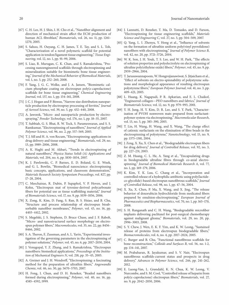
20 Journal of Nanomaterials
[67] C. H. Lee, H. J. Shin, I. H. Cho et al., “Nanofiber alignment anddirection of mechanical strain affect the ECM production ofhuman ACL fibroblast,” Biomaterials, vol. 26, no. 11, pp. 1261–1270, 2005.
[68] S. Sahoo, H. Ouyang, C. H. James, T. E. Tay, and S. L. Toh,“Characterization of a novel polymeric scaffold for potentialapplication in tendon/ligament tissue engineering,”Tissue Engi-neering, vol. 12, no. 1, pp. 91–99, 2006.
[69] S. Liao, R. Murugan, C. K. Chan, and S. Ramakrishna, “Pro-cessing nanoengineered scaffolds through electrospinning andmineralization suitable for biomimetic bone tissue engineer-ing,” Journal of theMechanical Behavior of BiomedicalMaterials,vol. 1, no. 3, pp. 252–260, 2008.
[70] F. Yang, J. G. C. Wolke, and J. A. Jansen, “Biomimetic cal-cium phosphate coating on electrospun poly(𝜀-caprolactone)scaffolds for bone tissue engineering,” Chemical EngineeringJournal, vol. 137, no. 1, pp. 154–161, 2008.
[71] J. C. J. Hogan and P. Biswas, “Narrow size distribution nanopar-ticle production by electrospray processing of ferritin,” Journalof Aerosol Science, vol. 39, no. 5, pp. 432–440, 2008.
[72] A. Jaworek, “Micro- and nanoparticle production by electro-spraying,” Powder Technology, vol. 176, no. 1, pp. 18–35, 2007.
[73] T. Subbiah, G. S. Bhat, R. W. Tock, S. Parameswaran, and S. S.Ramkumar, “Electrospinning of nanofibers,” Journal of AppliedPolymer Science, vol. 96, no. 2, pp. 557–569, 2005.
[74] T. J. Sill and H. A. von Recum, “Electrospinning: applications indrug delivery and tissue engineering,” Biomaterials, vol. 29, no.13, pp. 1989–2006, 2008.
[75] A. K. Haghi and M. Akbari, “Trends in electrospinning ofnatural nanofibers,” Physica Status Solidi (A) Applications andMaterials, vol. 204, no. 6, pp. 1830–1834, 2007.
[76] K. J. Pawlowski, C. P. Barnes, E. D. Boland, G. E. Wnek,and G. L. Bowlin, “Biomedical nanoscience: electrospinningbasic concepts, applications, and classroom demonstration,”Materials Research Society Symposium Proceedings, vol. 827, pp.17–28, 2004.
[77] C. Meechaisue, R. Dubin, P. Supaphol, V. P. Hoven, and J.Kohn, “Electrospun mat of tyrosine-derived polycarbonatefibers for potential use as tissue scaffolding material,” Journalof Biomaterials Science, vol. 17, no. 9, pp. 1039–1056, 2006.
[78] X. Zong, K. Kim, D. Fang, S. Ran, B. S. Hsiao, and B. Chu,“Structure and process relationship of electrospun bioab-sorbable nanofiber membranes,” Polymer, vol. 43, no. 16, pp.4403–4412, 2002.
[79] S. Megelski, J. S. Stephens, D. Bruce Chase, and J. F. Rabolt,“Micro- and nanostructured surface morphology on electro-spun polymer fibers,”Macromolecules, vol. 35, no. 22, pp. 8456–8466, 2002.
[80] S. A.Theron, E. Zussman, and A. L. Yarin, “Experimental inves-tigation of the governing parameters in the electrospinning ofpolymer solutions,” Polymer, vol. 45, no. 6, pp. 2017–2030, 2004.
[81] J. Venugopal, Y. Z. Zhang, and S. Ramakrishna, “Electrospunnanofibers: biomedical applications,” Proceedings of the Institu-tion of Mechanical Engineers N, vol. 218, pp. 35–45, 2005.
[82] A. Greiner and J. H. Wendorff, “Electrospinning: a fascinatingmethod for the preparation of ultrathin fibers,” AngewandteChemie, vol. 46, no. 30, pp. 5670–5703, 2007.
[83] H. Fong, I. Chun, and D. H. Reneker, “Beaded nanofibersformed during electrospinning,” Polymer, vol. 40, no. 16, pp.4585–4592, 1999.
[84] J. Lannutti, D. Reneker, T. Ma, D. Tomasko, and D. Farson,“Electrospinning for tissue engineering scaffolds,” MaterialsScience and Engineering C, vol. 27, no. 3, pp. 504–509, 2007.
[85] Q. Yang, L. I. Zhenyu, Y. Hong et al., “Influence of solventson the formation of ultrathin uniform poly(vinyl pyrrolidone)nanofibers with electrospinning,” Journal of Polymer Science B,vol. 42, no. 20, pp. 3721–3726, 2004.
[86] W. K. Son, J. H. Youk, T. S. Lee, and W. H. Park, “The effectsof solution properties and polyelectrolyte on electrospinning ofultrafine poly(ethylene oxide) fibers,” Polymer, vol. 45, no. 9, pp.2959–2966, 2004.
[87] T. Jarusuwannapoom,W.Hongrojjanawiwat, S. Jitjaicham et al.,“Effect of solvents on electro-spinnability of polystyrene solu-tions and morphological appearance of resulting electrospunpolystyrene fibers,” European Polymer Journal, vol. 41, no. 3, pp.409–421, 2005.
[88] L. Huang, K. Nagapudi, P. R. Apkarian, and E. L. Chaikof,“Engineered collagen—PEO nanofibers and fabrics,” Journal ofBiomaterials Science, vol. 12, no. 9, pp. 979–993, 2001.
[89] Y. H. Jung, H. Y. Kim, D. R. Lee, and S. Y. Park, “Character-ization of PVOH nonwoven mats prepared from surfactant-polymer system via electrospinning,”Macromolecular Research,vol. 13, no. 5, pp. 385–390, 2005.
[90] T. Lin, H. Wang, H. Wang, and X. Wang, “The charge effectof cationic surfactants on the elimination of fibre beads in theelectrospinning of polystyrene,” Nanotechnology, vol. 15, no. 9,pp. 1375–1381, 2004.
[91] J. Zeng, X. Xu, X. Chen et al., “Biodegradable electrospun fibersfor drug delivery,” Journal of Controlled Release, vol. 92, no. 3,pp. 227–231, 2003.
[92] Z. M. Huang, C. L. He, A. Yang et al., “Encapsulating drugsin biodegradable ultrafine fibres through co-axial electro-spinning,” Journal of Biomedical Materials Research A, vol. 77,no. 1, pp. 169–179, 2006.
[93] K. Kim, Y. K. Luu, C. Chang et al., “Incorporation andcontrolled release of a hydrophilic antibiotic using poly(lactide-co-glycolide)-based electrospun nanofibrous scaffolds,” Journalof Controlled Release, vol. 98, no. 1, pp. 47–56, 2004.
[94] X. Xu, X. Chen, P. Ma, X. Wang, and X. Jing, “The releasebehavior of doxorubicin hydrochloride from medicated fibersprepared by emulsion-electrospinning,” European Journal ofPharmaceutics and Biopharmaceutics, vol. 70, no. 1, pp. 165–170,2008.
[95] S. H. Ranganath and C. H. Wang, “Biodegradable microfiberimplants delivering paclitaxel for post-surgical chemotherapyagainst malignant glioma,” Biomaterials, vol. 29, no. 20, pp.2996–3003, 2008.
[96] S. Y. Chew, J. Wen, E. K. F. Yim, and K. W. Leong, “Sustainedrelease of proteins from electrospun biodegradable fibers,”Biomacromolecules, vol. 6, no. 4, pp. 2017–2024, 2005.
[97] C. Burger and B. Chu, “Functional nanofibrous scaffolds forbone reconstruction,” Colloids and Surfaces B, vol. 56, no. 1-2,pp. 134–141, 2007.
[98] M. Prabaharan, R. Jayakumar, and S. V. Nair, “Electrospunnanofibrous scaffolds-current status and prospects in drugdelivery,” Advances in Polymer Science, vol. 246, pp. 241–262,2012.
[99] E. Luong-Van, L. Grøndahl, K. N. Chua, K. W. Leong, V.Nurcombe, and S. M. Cool, “Controlled release of heparin frompoly(𝜀-caprolactone) electrospun fibers,” Biomaterials, vol. 27,no. 9, pp. 2042–2050, 2006.
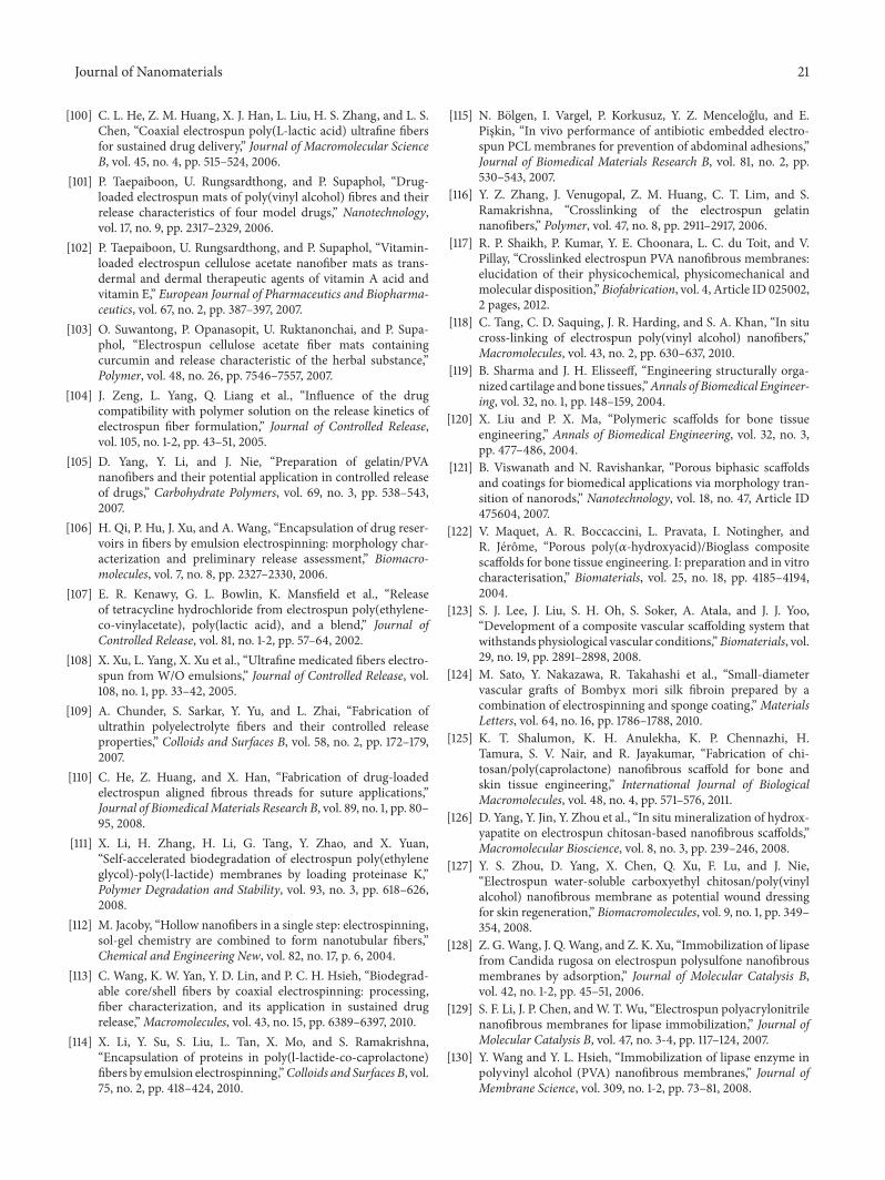
Journal of Nanomaterials 21
[100] C. L. He, Z. M. Huang, X. J. Han, L. Liu, H. S. Zhang, and L. S.Chen, “Coaxial electrospun poly(L-lactic acid) ultrafine fibersfor sustained drug delivery,” Journal of Macromolecular ScienceB, vol. 45, no. 4, pp. 515–524, 2006.
[101] P. Taepaiboon, U. Rungsardthong, and P. Supaphol, “Drug-loaded electrospun mats of poly(vinyl alcohol) fibres and theirrelease characteristics of four model drugs,” Nanotechnology,vol. 17, no. 9, pp. 2317–2329, 2006.
[102] P. Taepaiboon, U. Rungsardthong, and P. Supaphol, “Vitamin-loaded electrospun cellulose acetate nanofiber mats as trans-dermal and dermal therapeutic agents of vitamin A acid andvitamin E,” European Journal of Pharmaceutics and Biopharma-ceutics, vol. 67, no. 2, pp. 387–397, 2007.
[103] O. Suwantong, P. Opanasopit, U. Ruktanonchai, and P. Supa-phol, “Electrospun cellulose acetate fiber mats containingcurcumin and release characteristic of the herbal substance,”Polymer, vol. 48, no. 26, pp. 7546–7557, 2007.
[104] J. Zeng, L. Yang, Q. Liang et al., “Influence of the drugcompatibility with polymer solution on the release kinetics ofelectrospun fiber formulation,” Journal of Controlled Release,vol. 105, no. 1-2, pp. 43–51, 2005.
[105] D. Yang, Y. Li, and J. Nie, “Preparation of gelatin/PVAnanofibers and their potential application in controlled releaseof drugs,” Carbohydrate Polymers, vol. 69, no. 3, pp. 538–543,2007.
[106] H. Qi, P. Hu, J. Xu, and A. Wang, “Encapsulation of drug reser-voirs in fibers by emulsion electrospinning: morphology char-acterization and preliminary release assessment,” Biomacro-molecules, vol. 7, no. 8, pp. 2327–2330, 2006.
[107] E. R. Kenawy, G. L. Bowlin, K. Mansfield et al., “Releaseof tetracycline hydrochloride from electrospun poly(ethylene-co-vinylacetate), poly(lactic acid), and a blend,” Journal ofControlled Release, vol. 81, no. 1-2, pp. 57–64, 2002.
[108] X. Xu, L. Yang, X. Xu et al., “Ultrafine medicated fibers electro-spun from W/O emulsions,” Journal of Controlled Release, vol.108, no. 1, pp. 33–42, 2005.
[109] A. Chunder, S. Sarkar, Y. Yu, and L. Zhai, “Fabrication ofultrathin polyelectrolyte fibers and their controlled releaseproperties,” Colloids and Surfaces B, vol. 58, no. 2, pp. 172–179,2007.
[110] C. He, Z. Huang, and X. Han, “Fabrication of drug-loadedelectrospun aligned fibrous threads for suture applications,”Journal of BiomedicalMaterials Research B, vol. 89, no. 1, pp. 80–95, 2008.
[111] X. Li, H. Zhang, H. Li, G. Tang, Y. Zhao, and X. Yuan,“Self-accelerated biodegradation of electrospun poly(ethyleneglycol)-poly(l-lactide) membranes by loading proteinase K,”Polymer Degradation and Stability, vol. 93, no. 3, pp. 618–626,2008.
[112] M. Jacoby, “Hollow nanofibers in a single step: electrospinning,sol-gel chemistry are combined to form nanotubular fibers,”Chemical and Engineering New, vol. 82, no. 17, p. 6, 2004.
[113] C. Wang, K. W. Yan, Y. D. Lin, and P. C. H. Hsieh, “Biodegrad-able core/shell fibers by coaxial electrospinning: processing,fiber characterization, and its application in sustained drugrelease,”Macromolecules, vol. 43, no. 15, pp. 6389–6397, 2010.
[114] X. Li, Y. Su, S. Liu, L. Tan, X. Mo, and S. Ramakrishna,“Encapsulation of proteins in poly(l-lactide-co-caprolactone)fibers by emulsion electrospinning,”Colloids and Surfaces B, vol.75, no. 2, pp. 418–424, 2010.
[115] N. Bolgen, I. Vargel, P. Korkusuz, Y. Z. Menceloglu, and E.Piskin, “In vivo performance of antibiotic embedded electro-spun PCL membranes for prevention of abdominal adhesions,”Journal of Biomedical Materials Research B, vol. 81, no. 2, pp.530–543, 2007.
[116] Y. Z. Zhang, J. Venugopal, Z. M. Huang, C. T. Lim, and S.Ramakrishna, “Crosslinking of the electrospun gelatinnanofibers,” Polymer, vol. 47, no. 8, pp. 2911–2917, 2006.
[117] R. P. Shaikh, P. Kumar, Y. E. Choonara, L. C. du Toit, and V.Pillay, “Crosslinked electrospun PVA nanofibrous membranes:elucidation of their physicochemical, physicomechanical andmolecular disposition,”Biofabrication, vol. 4, Article ID 025002,2 pages, 2012.
[118] C. Tang, C. D. Saquing, J. R. Harding, and S. A. Khan, “In situcross-linking of electrospun poly(vinyl alcohol) nanofibers,”Macromolecules, vol. 43, no. 2, pp. 630–637, 2010.
[119] B. Sharma and J. H. Elisseeff, “Engineering structurally orga-nized cartilage and bone tissues,”Annals of Biomedical Engineer-ing, vol. 32, no. 1, pp. 148–159, 2004.
[120] X. Liu and P. X. Ma, “Polymeric scaffolds for bone tissueengineering,” Annals of Biomedical Engineering, vol. 32, no. 3,pp. 477–486, 2004.
[121] B. Viswanath and N. Ravishankar, “Porous biphasic scaffoldsand coatings for biomedical applications via morphology tran-sition of nanorods,” Nanotechnology, vol. 18, no. 47, Article ID475604, 2007.
[122] V. Maquet, A. R. Boccaccini, L. Pravata, I. Notingher, andR. Jerome, “Porous poly(𝛼-hydroxyacid)/Bioglass compositescaffolds for bone tissue engineering. I: preparation and in vitrocharacterisation,” Biomaterials, vol. 25, no. 18, pp. 4185–4194,2004.
[123] S. J. Lee, J. Liu, S. H. Oh, S. Soker, A. Atala, and J. J. Yoo,“Development of a composite vascular scaffolding system thatwithstands physiological vascular conditions,”Biomaterials, vol.29, no. 19, pp. 2891–2898, 2008.
[124] M. Sato, Y. Nakazawa, R. Takahashi et al., “Small-diametervascular grafts of Bombyx mori silk fibroin prepared by acombination of electrospinning and sponge coating,”MaterialsLetters, vol. 64, no. 16, pp. 1786–1788, 2010.
[125] K. T. Shalumon, K. H. Anulekha, K. P. Chennazhi, H.Tamura, S. V. Nair, and R. Jayakumar, “Fabrication of chi-tosan/poly(caprolactone) nanofibrous scaffold for bone andskin tissue engineering,” International Journal of BiologicalMacromolecules, vol. 48, no. 4, pp. 571–576, 2011.
[126] D. Yang, Y. Jin, Y. Zhou et al., “In situ mineralization of hydrox-yapatite on electrospun chitosan-based nanofibrous scaffolds,”Macromolecular Bioscience, vol. 8, no. 3, pp. 239–246, 2008.
[127] Y. S. Zhou, D. Yang, X. Chen, Q. Xu, F. Lu, and J. Nie,“Electrospun water-soluble carboxyethyl chitosan/poly(vinylalcohol) nanofibrous membrane as potential wound dressingfor skin regeneration,” Biomacromolecules, vol. 9, no. 1, pp. 349–354, 2008.
[128] Z. G.Wang, J. Q.Wang, and Z. K. Xu, “Immobilization of lipasefrom Candida rugosa on electrospun polysulfone nanofibrousmembranes by adsorption,” Journal of Molecular Catalysis B,vol. 42, no. 1-2, pp. 45–51, 2006.
[129] S. F. Li, J. P. Chen, andW. T. Wu, “Electrospun polyacrylonitrilenanofibrous membranes for lipase immobilization,” Journal ofMolecular Catalysis B, vol. 47, no. 3-4, pp. 117–124, 2007.
[130] Y. Wang and Y. L. Hsieh, “Immobilization of lipase enzyme inpolyvinyl alcohol (PVA) nanofibrous membranes,” Journal ofMembrane Science, vol. 309, no. 1-2, pp. 73–81, 2008.
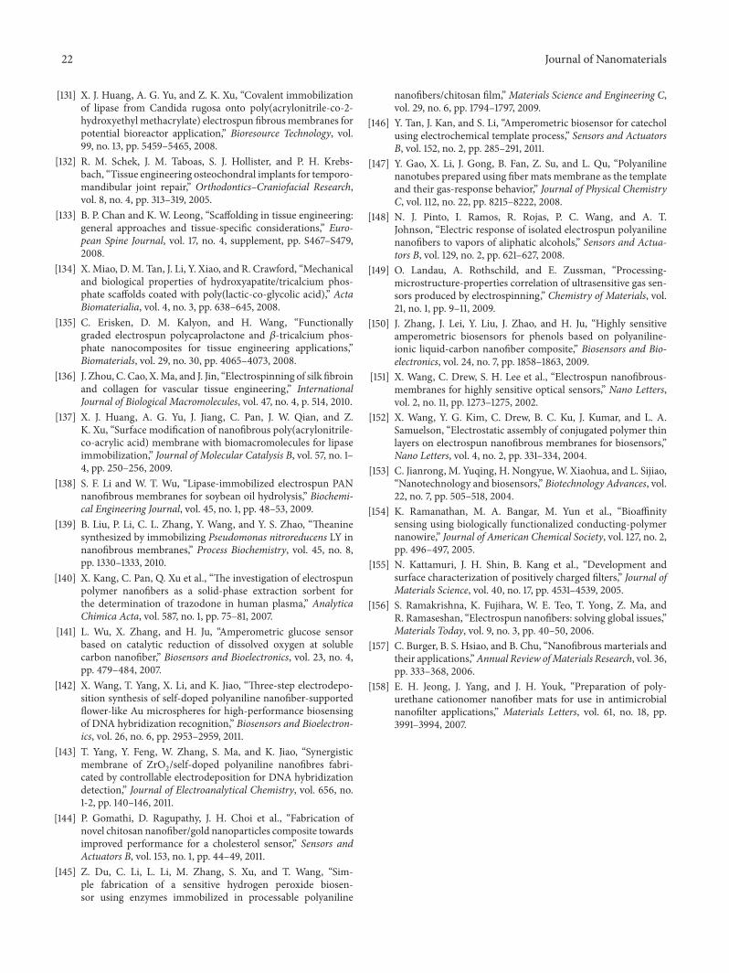
22 Journal of Nanomaterials
[131] X. J. Huang, A. G. Yu, and Z. K. Xu, “Covalent immobilizationof lipase from Candida rugosa onto poly(acrylonitrile-co-2-hydroxyethyl methacrylate) electrospun fibrousmembranes forpotential bioreactor application,” Bioresource Technology, vol.99, no. 13, pp. 5459–5465, 2008.
[132] R. M. Schek, J. M. Taboas, S. J. Hollister, and P. H. Krebs-bach, “Tissue engineering osteochondral implants for temporo-mandibular joint repair,” Orthodontics–Craniofacial Research,vol. 8, no. 4, pp. 313–319, 2005.
[133] B. P. Chan and K. W. Leong, “Scaffolding in tissue engineering:general approaches and tissue-specific considerations,” Euro-pean Spine Journal, vol. 17, no. 4, supplement, pp. S467–S479,2008.
[134] X.Miao, D.M. Tan, J. Li, Y. Xiao, and R. Crawford, “Mechanicaland biological properties of hydroxyapatite/tricalcium phos-phate scaffolds coated with poly(lactic-co-glycolic acid),” ActaBiomaterialia, vol. 4, no. 3, pp. 638–645, 2008.
[135] C. Erisken, D. M. Kalyon, and H. Wang, “Functionallygraded electrospun polycaprolactone and 𝛽-tricalcium phos-phate nanocomposites for tissue engineering applications,”Biomaterials, vol. 29, no. 30, pp. 4065–4073, 2008.
[136] J. Zhou, C. Cao, X.Ma, and J. Jin, “Electrospinning of silk fibroinand collagen for vascular tissue engineering,” InternationalJournal of Biological Macromolecules, vol. 47, no. 4, p. 514, 2010.
[137] X. J. Huang, A. G. Yu, J. Jiang, C. Pan, J. W. Qian, and Z.K. Xu, “Surface modification of nanofibrous poly(acrylonitrile-co-acrylic acid) membrane with biomacromolecules for lipaseimmobilization,” Journal of Molecular Catalysis B, vol. 57, no. 1–4, pp. 250–256, 2009.
[138] S. F. Li and W. T. Wu, “Lipase-immobilized electrospun PANnanofibrous membranes for soybean oil hydrolysis,” Biochemi-cal Engineering Journal, vol. 45, no. 1, pp. 48–53, 2009.
[139] B. Liu, P. Li, C. L. Zhang, Y. Wang, and Y. S. Zhao, “Theaninesynthesized by immobilizing Pseudomonas nitroreducens LY innanofibrous membranes,” Process Biochemistry, vol. 45, no. 8,pp. 1330–1333, 2010.
[140] X. Kang, C. Pan, Q. Xu et al., “The investigation of electrospunpolymer nanofibers as a solid-phase extraction sorbent forthe determination of trazodone in human plasma,” AnalyticaChimica Acta, vol. 587, no. 1, pp. 75–81, 2007.
[141] L. Wu, X. Zhang, and H. Ju, “Amperometric glucose sensorbased on catalytic reduction of dissolved oxygen at solublecarbon nanofiber,” Biosensors and Bioelectronics, vol. 23, no. 4,pp. 479–484, 2007.
[142] X. Wang, T. Yang, X. Li, and K. Jiao, “Three-step electrodepo-sition synthesis of self-doped polyaniline nanofiber-supportedflower-like Au microspheres for high-performance biosensingof DNA hybridization recognition,” Biosensors and Bioelectron-ics, vol. 26, no. 6, pp. 2953–2959, 2011.
[143] T. Yang, Y. Feng, W. Zhang, S. Ma, and K. Jiao, “Synergisticmembrane of ZrO
2
/self-doped polyaniline nanofibres fabri-cated by controllable electrodeposition for DNA hybridizationdetection,” Journal of Electroanalytical Chemistry, vol. 656, no.1-2, pp. 140–146, 2011.
[144] P. Gomathi, D. Ragupathy, J. H. Choi et al., “Fabrication ofnovel chitosan nanofiber/gold nanoparticles composite towardsimproved performance for a cholesterol sensor,” Sensors andActuators B, vol. 153, no. 1, pp. 44–49, 2011.
[145] Z. Du, C. Li, L. Li, M. Zhang, S. Xu, and T. Wang, “Sim-ple fabrication of a sensitive hydrogen peroxide biosen-sor using enzymes immobilized in processable polyaniline
nanofibers/chitosan film,”Materials Science and Engineering C,vol. 29, no. 6, pp. 1794–1797, 2009.
[146] Y. Tan, J. Kan, and S. Li, “Amperometric biosensor for catecholusing electrochemical template process,” Sensors and ActuatorsB, vol. 152, no. 2, pp. 285–291, 2011.
[147] Y. Gao, X. Li, J. Gong, B. Fan, Z. Su, and L. Qu, “Polyanilinenanotubes prepared using fiber mats membrane as the templateand their gas-response behavior,” Journal of Physical ChemistryC, vol. 112, no. 22, pp. 8215–8222, 2008.
[148] N. J. Pinto, I. Ramos, R. Rojas, P. C. Wang, and A. T.Johnson, “Electric response of isolated electrospun polyanilinenanofibers to vapors of aliphatic alcohols,” Sensors and Actua-tors B, vol. 129, no. 2, pp. 621–627, 2008.
[149] O. Landau, A. Rothschild, and E. Zussman, “Processing-microstructure-propertıes correlation of ultrasensitive gas sen-sors produced by electrospinning,” Chemistry of Materials, vol.21, no. 1, pp. 9–11, 2009.
[150] J. Zhang, J. Lei, Y. Liu, J. Zhao, and H. Ju, “Highly sensitiveamperometric biosensors for phenols based on polyaniline-ionic liquid-carbon nanofiber composite,” Biosensors and Bio-electronics, vol. 24, no. 7, pp. 1858–1863, 2009.
[151] X. Wang, C. Drew, S. H. Lee et al., “Electrospun nanofibrous-membranes for highly sensitive optical sensors,” Nano Letters,vol. 2, no. 11, pp. 1273–1275, 2002.
[152] X. Wang, Y. G. Kim, C. Drew, B. C. Ku, J. Kumar, and L. A.Samuelson, “Electrostatic assembly of conjugated polymer thinlayers on electrospun nanofibrous membranes for biosensors,”Nano Letters, vol. 4, no. 2, pp. 331–334, 2004.
[153] C. Jianrong, M. Yuqing, H. Nongyue, W. Xiaohua, and L. Sijiao,“Nanotechnology and biosensors,” Biotechnology Advances, vol.22, no. 7, pp. 505–518, 2004.
[154] K. Ramanathan, M. A. Bangar, M. Yun et al., “Bioaffinitysensing using biologically functionalized conducting-polymernanowire,” Journal of American Chemical Society, vol. 127, no. 2,pp. 496–497, 2005.
[155] N. Kattamuri, J. H. Shin, B. Kang et al., “Development andsurface characterization of positively charged filters,” Journal ofMaterials Science, vol. 40, no. 17, pp. 4531–4539, 2005.
[156] S. Ramakrishna, K. Fujihara, W. E. Teo, T. Yong, Z. Ma, andR. Ramaseshan, “Electrospun nanofibers: solving global issues,”Materials Today, vol. 9, no. 3, pp. 40–50, 2006.
[157] C. Burger, B. S. Hsiao, and B. Chu, “Nanofibrous marterials andtheir applications,”Annual Review ofMaterials Research, vol. 36,pp. 333–368, 2006.
[158] E. H. Jeong, J. Yang, and J. H. Youk, “Preparation of poly-urethane cationomer nanofiber mats for use in antimicrobialnanofilter applications,” Materials Letters, vol. 61, no. 18, pp.3991–3994, 2007.

Submit your manuscripts athttp://www.hindawi.com
ScientificaHindawi Publishing Corporationhttp://www.hindawi.com Volume 2014
CorrosionInternational Journal of
Hindawi Publishing Corporationhttp://www.hindawi.com Volume 2014
Polymer ScienceInternational Journal of
Hindawi Publishing Corporationhttp://www.hindawi.com Volume 2014
Hindawi Publishing Corporationhttp://www.hindawi.com Volume 2014
CeramicsJournal of
Hindawi Publishing Corporationhttp://www.hindawi.com Volume 2014
CompositesJournal of
NanoparticlesJournal of
Hindawi Publishing Corporationhttp://www.hindawi.com Volume 2014
Hindawi Publishing Corporationhttp://www.hindawi.com Volume 2014
International Journal of
Biomaterials
Hindawi Publishing Corporationhttp://www.hindawi.com Volume 2014
NanoscienceJournal of
TextilesHindawi Publishing Corporation http://www.hindawi.com Volume 2014
Journal of
NanotechnologyHindawi Publishing Corporationhttp://www.hindawi.com Volume 2014
Journal of
CrystallographyJournal of
Hindawi Publishing Corporationhttp://www.hindawi.com Volume 2014
The Scientific World JournalHindawi Publishing Corporation http://www.hindawi.com Volume 2014
Hindawi Publishing Corporationhttp://www.hindawi.com Volume 2014
CoatingsJournal of
Advances in
Materials Science and EngineeringHindawi Publishing Corporationhttp://www.hindawi.com Volume 2014
Smart Materials Research
Hindawi Publishing Corporationhttp://www.hindawi.com Volume 2014
Hindawi Publishing Corporationhttp://www.hindawi.com Volume 2014
MetallurgyJournal of
Hindawi Publishing Corporationhttp://www.hindawi.com Volume 2014
BioMed Research International
MaterialsJournal of
Hindawi Publishing Corporationhttp://www.hindawi.com Volume 2014
Nano
materials
Hindawi Publishing Corporationhttp://www.hindawi.com Volume 2014
Journal ofNanomaterials