Embed Size (px)
Citation preview

ENARCO, S.A.
es
MX-TEN-1005
en
fr
de
BANDEJAS REVERSIBLES REVERSIBLE PLATES PLATEAUX RÉVERSIBLES REVERSIERBARE PLATTEN
Manual de Instrucciones Instruction Manual
Manuel d’Instructions Bedienungsanweisung
TE
N25
40- T
EN
2550
-TE
N30
40- T
EN
3050

HOJA EN BLANCO

BANDEJAS REVERSIBLES 1
es
TEN2540-TEN2550-TEN3040-TEN3050
ÍNDICE
1 PRÓLOGO 3
2 INFORMACIÓN DE SEGURIDAD 4 2.1 SEGURIDAD EN LA OPERACIÓN DE LA MÁQUINA ................................ 4 2.2 SEGURIDAD EN LA OPERACIÓN DEL MOTOR......................................... 5 2.3 SEGURIDAD EN EL SERVICIO ..................................................................... 5 2.4 CALCOMANÍAS.............................................................................................. 6
3 RECICLAJE 7
4 DATOS TÉCNICOS 8 4.1 DATOS DEL MOTOR ...................................................................................... 8 4.2 DATOS DE LA MAQUINA ........................................................................... 8 4.3 INCLINACIÓN MÁXIMA DE LA BANDEJA EN
FUNCIONAMIENTO ....................................................................................... 9 4.4 MEDIDAS ACÚSTICAS Y VIBRATORIAS................................................... 9
5 INSTRUCCIONES DE OPERACIÓN 10 5.1 DESCRIPCIÓN DEL FUNCIONAMIENTO.................................................. 10 5.2 APLICACIONES ............................................................................................ 10 5.3 TRANSPORTE DE LA MÁQUINA ............................................................... 12
6 FUNCIONAMIENTO 13 6.1 ANTES DE INICIAR EL TRABAJO .............................................................. 14 6.2 PUESTA EN MARCHA.................................................................................. 14 6.3 TRABAJO ....................................................................................................... 15 6.4 PARADA DEL MOTOR ................................................................................. 16
7 MANTENIMIENTO 17 7.1 CALENDARIO DE MANTENIMIENTO....................................................... 17 7.2 CARACTERÍSTICAS DE LA BUJÍA DEL MOTOR Y SERVICIO
(HONDA / ROBIN). ........................................................................................ 18 7.3 MANTENIMIENTO DEL FILTRO DE AIRE ................................................ 19 7.4 CAMBIO DE ACEITE DEL MOTOR............................................................. 21 7.5 AJUSTE DE VELOCIDAD DEL MOTOR (MOTOR HONDA /
ROBIN)............................................................................................................ 22 7.6 AJUSTE DEL CARBURADOR (MOTOR HONDA / ROBIN) ...................... 22

BANDEJAS REVERSIBLES
es
2 TEN2540-TEN2550-TEN3040-TEN3050
7.7 LIMPIEZA DE LA TAZA DE SEDIMENTOS (MOTOR HONDA / ROBIN)............................................................................................................ 23
7.8 CAMBIO DE FILTRO DE COMBUSTIBLE (MOTOR HATZ) .................... 24 7.9 LIMPIEZA DE FILTRO DE ACEITE (MOTOR HATZ)................................ 24 7.10 TENSADO CORRECTO Y ESPECIFICACIÓN DE LA CORREA ............. 25 7.11 CAMBIAR CORREA TRAPEZOIDAL........................................................ 25 7.12 MANTENIMIENTO DEL CONJUNTO VIBRANTE .................................. 26 7.13 MANTENIMIENTO DEL MANDO HIDRÁULICO.................................... 27 7.14 LOCALIZACIÓN Y REPARACIÓN DE AVERÍAS.................................... 28
8 EN CASO DE AVERÍAS 32 8.1 INTRUCCIONES PARA PEDIR REPUESTOS ............................................. 32 8.2 INTRUCCIONES PARA SOLICITAR GARANTÍAS ................................... 32
9 DIRECCIONES DE INTERÉS 33

BANDEJAS REVERSIBLES 3
es
TEN2540-TEN2550-TEN3040-TEN3050
1 PRÓLOGO Agradecemos la confianza depositada en la marca ENAR. La lectura del presente manual es importante para el completo conocimiento de las
características y operaciones de trabajo de la bandeja compactadora. Antes de comenzar a trabajar con esta máquina o de realizar operaciones de mantenimiento en ella lea, comprenda y cumpla las instrucciones de seguridad de este manual.
En caso de pérdida de este manual o de necesitar un ejemplar adicional solicítelo a ENARCO o
acceda a él en formato electrónico en la página web de ENARCO: http://www.enar.es e imprímalo. Los procedimientos correctos de mantenimiento aseguran la larga duración y un excelente
trabajo de la unidad. Aunque el presente manual da algunas indicaciones acerca del motor, recomendamos la
consulta del manual de instrucciones del motor, en lo que al mantenimiento y reparaciones del motor se refiere.
Si necesita información acerca de la operación o mantenimiento de esta máquina póngase en
contacto con el servicio de asistencia de ENARCO llamando por teléfono, enviando un fax, realizando una consulta por correo electrónico a [email protected] o a través de la página web en el apartado Servicio ENAR.

BANDEJAS REVERSIBLES
es
4 TEN2540-TEN2550-TEN3040-TEN3050
2 INFORMACIÓN DE SEGURIDAD
2.1 SEGURIDAD EN LA OPERACIÓN DE LA MÁQUINA
El uso o mantenimiento incorrectos del equipo pueden generar situaciones de peligro. Lea y asimile las instrucciones de este apartado antes de empezar a trabajar con esta máquina. El operador del equipo debe responsabilizarse de que sabe trabajar con seguridad el equipo. Si tiene dudas solicite instrucción a personal conocedor de la máquina o contacte con ENARCO.
� El motor se calienta mucho durante su funcionamiento, déjelo enfriar antes de tocarlo.
� No deje nunca la máquina en marcha sin atención.
� No debe usar el equipo sin la adecuada protección del cubrecorreas. Verifique siempre que no falta y que está en buenas condiciones.
� El operario debe usar ropa de protección y protecctores auditivos.
� Impida el acceso al área de trabajo de personal no autorizado.
� Asegurese de que sabe desconectar la máquina antes de poner el motor en marcha por si se encuentra en dificultades.
� Pare la máquina antes de transportarla.
� No intente levantar el equipo sin ayuda. Solicite ayuda o emplee un aparato de elevación usando el asa de izado integrada en la jaula de la bandeja.
� No utilice el equipo si no se encuentra en buenas condiciones físicas.
� Almacene el equipo de modo adecuado en un lugar limpio y seco cuando no lo vaya a usar. Los combustibles y demás consumibles deberán ser almacenados en recipientes marcados siguiendo las indicaciones de sus fabricantes. Respete así mismo las disposiciones legales vigentes en el lugar de almacenaje.
� Modificaciones y adaptaciones: por razones de seguridad, está completamente prohibido realizar cualquier clase de modificación o adaptación al equipo, incluido variar el número de revoluciones del motor regulado en fábrica, sin la autorización previa de ENARCO. Ante cualquier responsabilidad derivada del incumplimiento de esta instrucción ENARCO quedará exento.
!

BANDEJAS REVERSIBLES 5
es
TEN2540-TEN2550-TEN3040-TEN3050
2.2 SEGURIDAD EN LA OPERACIÓN DEL MOTOR
A causa de su alta inflamabilidad los combustibles son especialmente peligrosos. Su uso inadecuado puede graves daños personales y materiales. Cumpla siempre con las siguientes reglas de seguridad:
� No haga funcionar el equipo dentro de un edificio o zonas cerradas de no existir un ventilación adecuada. En caso contrario puede sufrir intoxicación por monóxido de carbono con perdida de conocimiento, pudiendo llegar hasta la muerte.
� Antes de rellenar el depósito de combustible, pare el motor y déjelo enfriar unos minutos.
� No debe fumar durante el funcionamiento de la máquina, ni durante el repostaje.
� No rellene el depósito cerca de una llama abierta y rellénelo en un área bien ventilada.
� Sustituya inmediatamente el tanque de combustible si no es hermético, podría ser causa de explosiones.
� Si durante el repostaje se derrama carburante empápelo en arena. Cámbiese de ropa si le cae combustible sobre ella.
� Asegúrese de que el depósito de combustible está bien cerrado después de rellenarlo.
� Compruebe que las tuberías y el depósito de combustible no tienen grietas ni fugas.
2.3 SEGURIDAD EN EL SERVICIO
� No limpie ni revise el equipo estando en funcionamiento.
� No arranque el motor con el cilindro inundado y habiendo retirado la bujía en los motores de gasolina.
� No compruebe que la bujía da chispa si el cilindro está inundado de gasolina o hay vapores de gasolina.
� No use disolventes o combustibles para limpiar el equipo, sobre todo en recintos cerrados.
� Mantenga el área próxima al silenciador libre de materiales inflamables.
� Antes de hacer operaciones de servicio en equipos con motor de gasolina remueva la bujía para evitar un arranque no previsto del motor.
� No está permitido el uso del equipo en atmósferas explosivas. El tanque de combustible debe cerrar herméticamente. En transportes de largo recorrido es altamente recomendable vaciar de combustible el depósito del motor.
� El accesorio de transporte no ha sido diseñado para estacionar sobre él la bandeja, utilícelo solamente para mover el equipo.
!

BANDEJAS REVERSIBLES
es
6 TEN2540-TEN2550-TEN3040-TEN3050
2.4 CALCOMANÍAS
CALCOMANÍA SIGNIFICADO
L WA
Nivel de potencia acústica en dB(A)
2004 A50012442
MOD:
NR:
Placa de identificación
Utilice protectores auditivos

BANDEJAS REVERSIBLES 7
es
TEN2540-TEN2550-TEN3040-TEN3050
3 RECICLAJE
Para ayudar a proteger el medio ambiente lleve la máquina a un taller de reciclado apropiado.
COMPONENTE MATERIAL Manillar Acero Jaula Acero Base motor Acero Base bandeja Acero Funda del manillar Caucho Soportes asidero Aluminio Motor Aluminio Amortiguadores Acero y caucho Correa Caucho Carcasas Aluminio Conjunto excéntrica Acero Soporte ruedas Acero Ruedas Plástico y CauchoEjes Acero
BANDEJAS REVERSIBLES
es
8 TEN2540-TEN2550-TEN3040-TEN3050
4 DATOS TÉCNICOS
4.1 DATOS DEL MOTOR
HATZ 1B20 ROBIN EX 17 HONDA GX160
COMBUSTIBLE Diesel Gasolina sin plomo (3,6 l)
Gasolina sin plomo (3,6 l)
ACEITE MOTOR SAE 10W/40 (0,9 l) SAE 10W/40 (0,6 l) SAE 10W/40 (0,6 l) POTENCIA NOMINAL
3,4 kW (4,6 HP) a 3000 rpm
4,2 kW (5,7 HP) a 3600 rpm
4 kW (5,4 HP) a 3600 rpm
BUJÍA ------ NGK BPR6ES DENSO W20EPR-U
ENTREHIERRO ------ 0,7 mm - 0,8 mm REVOLUCIONES 3000 ± 100 3600 ± 100
RALENTÍ 1100150200
�� r.p.m. 1400
150200
�� r.p.m.
FILTRO DEL AIRE ELEMENTO DOBLE ELEMENTO DOBLE
4.2 DATOS DE LA MAQUINA
CARACTERÍSTICAS MODELO UNIDAD TEN2540GH TEN2550GH TEN2540DH TEN2550DH TEN2540GR TEN2550GR FUERZA CENTRÍFUGA kN 25
ANCHURA DE TRABAJO mm 400 500 400 500 400 500 FREQUENCIA Hz.(r.p.m.) 90 (5400) 90 (5400) 85 (5300) 85 (5300) 90 (5400) 90 (5400)
DESPLAZAMIENTO m/min 0-22 0-22 0-20 0-20 0-22 0-22 PESO Kg 134 140 148 155 134 140
MOTOR HONDA GX160 HATZ 1B20 ROBIN EX17 ACEITE VIBRADOR c.c. 1000 (SAE 100)
CARACTERÍSTICAS MODELO
UNIDAD TEN3040GH TEN3050GH TEN3040DH TEN3050DH TEN3040GR TEN3050GR FUERZA CENTRÍFUGA kN 30
ANCHURA DE TRABAJO mm 400 500 400 500 400 500 FREQUENCIA Hz.(r.p.m.) 90 (5400) 90 (5400) 85 (5300) 85 (5300) 90 (5400) 90 (5400)
DESPLAZAMIENTO m/min 0-22 0-22 0-20 0-20 0-22 0-22 PESO Kg 134 140 148 155 134 140
MOTOR HONDA GX160 HATZ 1B20 ROBIN EX17 ACEITE VIBRADOR c.c. 1000 (SAE 100)

BANDEJAS REVERSIBLES 9
es
TEN2540-TEN2550-TEN3040-TEN3050
658
348
686
1171
935
500
400
1094
4.3 INCLINACIÓN MÁXIMA DE LA BANDEJA EN FUNCIONAMIENTO
20°
20°
4.4 MEDIDAS ACÚSTICAS Y VIBRATORIAS
- nivel de potencia acústica según ISO 3744: LWA � 102 dB(A)
- nivel de presión sonora según ISO 6081: LpA � 93 dB(A)
- valor efectivo ponderado de aceleración axial según ISO 8662 Parte 1: 5 - 10 m/s2
BANDEJAS REVERSIBLES
es
10 TEN2540-TEN2550-TEN3040-TEN3050
5 INSTRUCCIONES DE OPERACIÓN
5.1 DESCRIPCIÓN DEL FUNCIONAMIENTO
La vibración de la máquina se genera mediante excéntricas rotantes en el conjunto vibrante que está anclado a la base de la bandeja. Las excéntricas están dispuestas en dos ejes contrarrotantes. Variando el desfase entre las excéntricas contrarrotantes modificamos la composición de fuerzas generadas en el excitador y por tanto la dirección de las oscilaciones. Así podemos hacer que la máquina avance, permanezca en el sitio o retroceda. Esta regulación se realiza de forma continua y progresiva mediante el mando hidráulico situado en la cabeza de la barra de dirección. El conjunto vibrante es accionado por el motor térmico de la máquina, que está unido mediante pernos a la base motor. El par generado por el motor es transmitido al conjunto vibrante mediante el embrague centrífugo a la salida del motor y la correa en V que conecta los dos ejes. A bajas revoluciones el embrague centrífugo no actúa, así el motor el motor puede arrancar sin carga y marchar de forma suave al ralentí. Aunque mediante la palanca del acelerador se puede regular el régimen de giro del motor se debe llevar el motor a máximo régimen para que el embrague no patine. La base inferior de la bandeja está conectada a la base motor mediante cuatro amortiguadores que aminoran las vibraciones en la masa superior de la máquina, de este modo tanto el motor como el usuario pueden operar de un modo más seguro. Con el asidero girado a su posición más avanzada la bandeja avanza a su máxima velocidad hacia delante. Según se va retrocediendo el asidero disminuye la velocidad de avance del equipo hasta que ésta deja de avanzar. Si se continua retrocediendo el asidero, la bandeja comienza a marchar hacia atrás. Así hasta llegar al tope del asidero, momento en el que la máquina retrocede a su máxima velocidad
5.2 APLICACIONES
Esta bandeja es adecuada para compactar suelos granulares, grava y adoquines. Las bandejas con rociador pueden emplearse en la compactación de asfalto.
Las aplicaciones típicas para compactar suelos son rellenos de materia granular en redes de agua, teléfono, zanjas de ancho mediano, alrededor de tuberías, fundaciones y caminos o aceras para peatones y bicicletas.
Las aplicaciones en compactación de asfalto incluyen el parcheo y la reparación de huecos en carreteras.

BANDEJAS REVERSIBLES 11
es
TEN2540-TEN2550-TEN3040-TEN3050
MODELO
APLICACIÓN
Placas reversibles
Placas no reversibles
Pisones
Áreas de parcheo �� � ��Fundación de edificios � � �Caminos y paseos �� � �Canchas de tenis y deportes �� � �Preparación de base � �� ��Soporte final de puentes o rampas � � ��Cruce de ferrocarriles � � ��Bloques de cemento entrelazados �� � �Construcción de redes � �� �Construcción de drenajes � � �Compactación de zanjas. � � �Reparación de huecos por rotura de tuberías, cables, etc. �� �� ��
Alrededor de tuberías, cables, drenajes, etc.
�� �� ��
Relleno de rocas � � �Grava � � �Arena o material volcánico � � ��Suelos mixtos � �� �Fango � � �Arcilla � � �Espesor de capa 0 – 25 cm � � �Espesor de capa 20 – 40 cm � � �Mezcla caliente �� � ��Mezcla fría �� � ��Base - Capa de ligado 40 – 100 mm � �� �Capa de rodado 25 – 60 mm �� � �
� Recomendado � Puede ser usado � Desaconsejado

BANDEJAS REVERSIBLES
es
12 TEN2540-TEN2550-TEN3040-TEN3050
5.3 TRANSPORTE DE LA MÁQUINA
� Antes de transportar la bandeja, como se describe en el punto fdffdfd.
� Bloquee el mástil mediante su anclaje. Nunca use el mástil para elevar la máquina.
� Mover la bandeja cortas distancias o subirla a una furgoneta se debe hacer agarrando la bandeja de las asas de transporte entre dos personas.
� Para izarla mecánicamente :
o Verifique que los aparatos de elevación disponen de suficiente capacidad para elevar la máquina (ver punto 4.2 DATOS DE LA MAQUINA).
o Ponga el gancho de elevación o la eslinga al punto de anclaje en la jaula de la máquina del modo indicado en la siguiente ilustración.
o No se coloque nunca debajo de la carga suspendida.
� Las rampas de carga deberán ser sólidas y estables. Deberá tenerse cuidado de no poner en peligro a personas por posibles vuelcos o deslizamientos del equipo, como también por partes del mismo que pudieran golpear hacia arriba o hacia abajo.
� Para transportar la máquina en un vehículo:
o Deje enfríar el motor
o Cierre la llave de paso de combustible y mantega el motor de pie para evitar el vertido de combustible.
o Amarre la bandeja al vehículo para evitar deslizamientos o el vuelco.
BANDEJAS REVERSIBLES 13
es
TEN2540-TEN2550-TEN3040-TEN3050
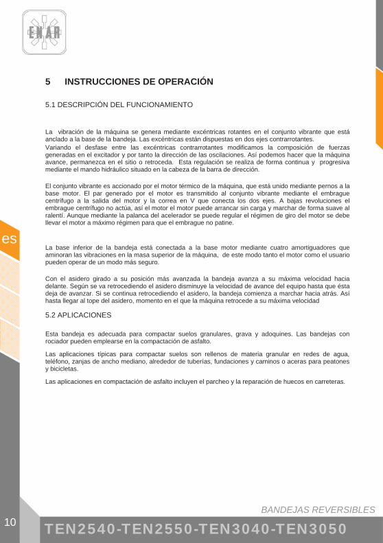
� Para desplazar la máquina por el suelo: o Fije el mástil de guiado con su anclaje. Coloque el accesorio conjunto ruedas
BW2549 en la parte delantera de la máquina con los gatillos de fijación abiertos apuntando a los puntos de anclaje
o Eche los dos gatillos de fijación de forma que el conjunto ruedas quede firmemente anclado a la máquina.
o Incline con el asidero la máquina hacia adelante ayudándose con el pie en la barra central del conjunto ruedas (A) y desplace la bandeja (B).
(A) (B) (C)
Cuando suelte la máquina hágalo con suavidad apoyando el pie en el estribo para que usted no sea proyectado ni dañe a la bandeja (C).
!

BANDEJAS REVERSIBLES
es
14 TEN2540-TEN2550-TEN3040-TEN3050
6 FUNCIONAMIENTO
6.1 ANTES DE INICIAR EL TRABAJO
6.1.1. Limpie la suciedad, barro, etc., de la unidad antes de empezar el trabajo. Debe prestar atención especial a la cara inferior de la placa vibratoria y a las zonas adyacentes a la entrada de aire de refrigeración del motor, al carburador y al filtro de aire. 6.1.2. Revise todos los tornillos y asegúrese de que están bien apretados. Los tornillos
aflojados pueden dañar la máquina. 6.1.3. Revise la tensión de la correa en V. La oscilación normal debe ser de 10 – 15 mm. (1/2”)
cuando las correas son oprimidas con fuerza en la mitad de la distancia entre las dos poleas. Si hay demasiada holgura en las correas, puede haber falta de impacto ó vibración descontrolada, causando daño a la máquina.
6.1.4. El estado del filtro de aire. 6.1.5. Revise el nivel de aceite del motor, y si lo encuentra bajo, debe ser rellenado. El motor
tiene una capacidad de aceite de 0,6 l. Use aceite de motor SAE10W/40. 6.1.6. Asegúrese de que la bandeja está nivelada durante la revisión. El nivel de aceite en el
vibrador debe llegar al nivel del tapón. Cambie de aceite cada mes ó cada 200 horas de trabajo. El vibrador tiene una capacidad de 120 c.c.
IMPORTANTE USE ACEITE SAE 10W/40 Efectúe el cambio con el aceite caliente. Para facilitar la salida del aceite usado, incline la máquina y golpee ligeramente el vibrador 6.1.7. En el motor se debe usar gasolina tipo normal sin plomo. Al rellenar el tanque de
gasolina, asegúrese de que se está usando el filtro.
6.2 PUESTA EN MARCHA
- MOTOR HONDA GX160 / ROBIN EX17
6.2.1. Abra la llave de combustible desplazando la palanca y ponga la palanca en la posición media abierta. Para poner en marcha el motor frío desplace la palanca del regulador de aire hasta la posición de cerrado. Cuando el motor está caliente, el regulador de aire debe estar abierto a medias o por completo. Si la puesta en marcha del motor resulta difícil, asegúrese de que la palanca del regulador de aire esté media abierta para evitar que el carburador sea anegado por exceso de combustible.
6.2.2. Al tirar de la cuerda de arranque, no apure al máximo toda la longitud, puede dañar el muelle de recuperación. No suelte la cuerda de golpe para repetir la puesta en marcha una vez arrancado el motor, mantenga el tirador en la mano y ceda despacio hasta que se recoja totalmente.
6.2.3. Después de arrancar el motor, vuelva a abrir completamente de forma gradual la palanca del regulador de aire. Deje el motor calentarse en velocidad mínima durante 3-5 minutos. Este procedimiento de calentar el motor en mínimas revoluciones es particularmente importante durante la temporada fría. Mientras el motor se esté calentando haga una revisión general de la máquina, para detectar cualquier anomalía.

BANDEJAS REVERSIBLES 15
es
TEN2540-TEN2550-TEN3040-TEN3050
- MOTOR HATZ 1B20
6.2.4. Lleve totalmente a la derecha la palanca de ABERTURA/ CIERRE de combustible para abrir el paso de combustible
6.2.5. En primer lugar lleve la palanca de ajuste de revoluciones hasta la posición STOP 6.2.6. Lleve la palanca de ajuste de revoluciones bien a la posición 1/2 START o bien a la
posición START, según considere conveniente. El arranque a bajas revoluciones ayudará a reducir los humos de escape.
6.2.7. Tire del cable de arranque utilizando el asa hasta que se note una ligera resistencia. Deje que el cable vuelva a su posición; de este modo podrá utilizarse la totalidad de la longitud del cable para arrancar el motor.
6.2.8. Sujete el asa con ambas manos. Comience a tirar del cable de arranque con fuerza y cada vez más rápido hasta que el motor arranque.
6.2.9. Repita este procedimiento hasta el encendido del motor. 6.2.10. Si después de varios intentos de arranque el escape comienza a emitir humo blanco,
mueva la palanca de control de velocidad a la posición STOP y tire del cable de arranque lentamente 5 veces. Repita el procedimiento de arranque,
6.3 TRABAJO
6.3.1. La palanca del acelerador, situada sobre el mango, controla el trabajo de la compactadora. Accione la palanca del acelerador desde la posición de ralentí hasta que el acelerador haga tope. Cuando la velocidad del motor alcanza las 2.300 r.p.m. aproximadamente, se acopla el embrague centrífugo. Si la velocidad del motor aumenta muy lentamente, puede ser que el embrague patine. No accione lentamente la palanca del acelerador. IMPORTANTE: En el momento en que el embrague centrífugo alcanza la velocidad de corte comienza la vibración en la caja de excéntricas.
6.3.2. Cuando trabaje con la bandeja el gatillo de fijación del asidero no debe estar accionado. 6.3.3. Para compactar asfalto, es recomendable impregnar la cara inferior de la placa vibratoria
con combustible diesel. Esto ayudará a prevenir que la placa se adhiera al asfalto. 6.3.4. Para compactar adoquines está previsto el uso de la plancha amortiguadora referencia
ENARCO C0028 para evitar causar daños en los adoquines. 6.3.5. Para suprimir la vibración, pase la palanca de forma rápida de la posición ON a OFF. 6.3.6. TRABAJO EN PENDIENTES
� Para la compactación de suelos en pendiente el operario debe situarse siempre en una posición más elevada que la máquina.
� No está permitido operar la máquina en pendientes superiores a la máxima capacidad de la máquina indicada en el punto datos técnicos.
� Cuando trabaje en pendientes sea extremadamente prudente y trabaje siempre en dirección hacia arriba o hacia abajo, nunca trabaje en dirección parcial o totalmente transversal a la pendiente.
� Comience siempre a trabajar desde abajo. � La humedad o los suelos excesivamente sueltos causan un escaso agarre de
la bandeja lo cual incrementa el riesgo de accidente. 6.3.7. Marchando hacia atrás el operario debe situarse a un lado del equipo de modo que no
pueda ser atrapado entre el equipo y un obstáculo. En el caso que esto no sea posible, como en zanjas estrechas se debe tener sumo cuidado para no causar atrapamientos y que la máquina no quede sin control.
6.3.8. Deberá tenerse sumo cuidado en la compactación de terrenos irregulares o con materiales gruesos. El operario debe estar situado sobre suelo seguro y firme.

BANDEJAS REVERSIBLES
es
16 TEN2540-TEN2550-TEN3040-TEN3050
6.4 PARADA DEL MOTOR
- MOTOR HONDA GX160 / ROBIN EX17
6.4.1. Antes de parar el motor, déjelo al ralentí durante 2-3 minutos y luego oprima el botón de parada en el mástil de la bandeja hasta que el motor se pare por completo.
6.4.2. Cierre la llave de combustible.
- MOTOR HATZ 1B20
6.4.3. Para parar el motor lleve la palanca del acelerador al ralentí, luego apriete el botón rojo de paro y no lo suelte hasta que se pare el motor. Verifique que al soltarlo el botón vuelve a su posición original.
6.4.4. Cierre el paso de combustible poniendo totalmente a la izquierda la palanca de ABERTURA/CIERRE de carburante.
Botón de parada

BANDEJAS REVERSIBLES 17
es
TEN2540-TEN2550-TEN3040-TEN3050
7 MANTENIMIENTO
7.1 CALENDARIO DE MANTENIMIENTO
Intervalos Zona de Mantenimiento Trabajo de Mantenimiento Punto
Motor - Comprobar nivel de aceite - Revisar filtro de aire
7.4 7.3
Motor Hatz - Verificar separador de agua Diario o cada 8 horas
Máquina - Revisar si hay daños, fugas o similares - Limpie la cara inferior de la placa vibratoria.
Motor - Cambio aceite motor - Comprobar conexiones roscadas - Limpieza del filtro de aire
7.4
7.3
Motor Hatz - Comprobar y ajustar holgura de válvulas
Primeras 20 ehoras
Máquina - Revisar y ajustar correa trapezoidal 7.10
Motor - Comprobar conexiones roscadas - Limpiar sistema de refrigeración
Semanal o cada 50 horas Máquina
- Revisar amortiguadores de goma - Comprobar nivel de aceite de vibrador - Revisar y ajustar correa trapezoidal
7.12
Motor - Cambio aceite motor 7.4
Motor Hatz - Limpiar la pieza reticulada del escape - Comprobar y ajustar la holgura de válvulas
Motor Honda / Robin - Limpiar la taza de sedimentos - Revisar bujía
7.7 7.2
Mensual o cada 250
horas
Máquina - Comprobar y ajustar apriete de tornillos - Mando hidráulico: ver nivel y rellenar en su caso.
7.13
Motor Hatz - Cambiar elemento del filtro de combustible 7.8 Semestral o
cada 500 horas Motor Honda / Robin
- Comprobar y ajustar graduación del carburador - Revisar y ajustar holgura de válvulas - Cambiar aceite del vibrador
7.6
7.12
Motor Hatz - Limpiar filtro de aceite 7.9
Motor Honda / Robin - Limpiar cámara de combustión - Limpiar deposito y filtro de combustible - Revisar el tubo de combustible
Anual o cada 1000
horas
Máquina - Quitar suciedad, grasa usada y reemplazar partes
oxidadas

BANDEJAS REVERSIBLES
es
18 TEN2540-TEN2550-TEN3040-TEN3050
Almacenamiento: Cuando guarde la bandeja un largo período de tiempo) A.- Vacíe completamente el combustible del tanque, del tubo de combustible y del carburador B.- Retire la bujía y eche algunas gotas de aceite de motor en el cilindro. Gire varias veces el motor a mano para que el aceite se distribuya en la superficie interior del cilindro. C.- Limpie la superficie externa de la máquina con un paño humedecido en aceite, cubra la unidad y guárdela en sitio libre de humedad y de polvo.
7.2 CARACTERÍSTICAS DE LA BUJÍA DEL MOTOR Y SERVICIO (HONDA / ROBIN).
Además del mantenimiento semanal prescrito en el calendario de mantenimiento, limpie o sustituya la bujía siempre que sea necesario para el buen funcionamiento del motor. Para ello consulte el manual de explicaciones del motor entregado con la bandeja. Consulte el punto 4.1 DATOS DEL MOTOR para elegir la bujía y para conocer el entrehierro. 7.2.1. Retire la tapa de la bujía y emplee una llave de bujías adecuada para extraer la bujía. 7.2.2. Revise visualmente la bujía y reemplácela si tiene desgaste aparente o si el aislador
está partido o rajado. 7.2.3. Si la bujía está correcta límpiela con un cepillo de alambre 7.2.4. Verifique que el entrehierro está entre 0,7 y 0,8 mm.
0.7 – 0.8 mm
7.2.5. Compruebe que la arandela de la bujía está en buenas condiciones e instale la bujía a
mano para evitar deformar la rosca. 7.2.6. Después apriete con la llave de bujías para comprimir la arandela.
Al instalar una bujía nueva, apriétela 1/2 vuelta después de que se asiente. Si la bujía está usada, apriétela entre 1/8 y 1/4 de vuelta después de su asentamiento. PRECAUCIÓN: la bujía debe estar firmemente apretada, porque sino se recalentará y podrá dañar al motor.

BANDEJAS REVERSIBLES 19
es
TEN2540-TEN2550-TEN3040-TEN3050
!
7.3 MANTENIMIENTO DEL FILTRO DE AIRE
Un filtro de aire sucio puede causar un mal funcionamiento del carburador. Limpie a menudo el filtro y más frecuentemente si trabajando se forma mucho polvo. PRECAUCIÓN: No emplee el motor sin filtro de aire, causará un rápido desgaste del motor.
Nunca limpie los elementos del filtro del motor con combustibles o disolventes de bajo punto de inflamación. Podrían ocurrir una explosión o un incendio.
MOTOR HONDA / ROBIN: 7.3.1. Desenrosque la tuerca de mariposa y retire la tapa del filtro de aire. Extraiga los
elementos, revíselos y cámbielos si tienen agujeros o están rajados. 7.3.2. Elemento de espuma: lávelo en una solución jabonosa y aclárelo perfectamente en agua
limpia. También puede lavarlo con disolventes que no sean inflamables. Deje que seque completamente. Empape el elemento en aceite limpio del motor y extrújelo para eliminar el exceso de aceite.
7.3.3. Elemento de papel: golpeelo levemente varias veces contra un superficie dura para expulsar el exceso de suciedad, o aplíquele aire comprimido desde el interior hacia fuera.
7.3.4. Volver a montar el cartucho siguiendo el orden inverso.

BANDEJAS REVERSIBLES
es
20 TEN2540-TEN2550-TEN3040-TEN3050
Motor Hatz
7.3.5. Soltar el tornillo de la tapa del filtro. 7.3.6. Sacar el cartucho del filtro del alojamiento del filtro de aire. Sacudirlo o soplarlo con baja
presión. 7.3.7. Insertar nuevamente el filtro. 7.3.8. Colocar nuevamente la tapa del alojamiento y asegurarla con el tornillo.
! PRECAUCIÓN:
� En caso de no lograrse con este procedimiento un grado de limpieza satisfactorio (Ej. Suciedad húmeda o grasosa), se deberá de colocar un nuevo cartucho de filtro.
� Verificar que la junta del cartucho no está dañada. � Comprobar que no hay grietas en el cartucho de filtro ni ningún otro tipo de
daño en el filtro de papel, colocándolo contra la luz o iluminándolo con una fuente de luz.

BANDEJAS REVERSIBLES 21
es
TEN2540-TEN2550-TEN3040-TEN3050
7.4 CAMBIO DE ACEITE DEL MOTOR
7.4.1. El motor debe estar en posición nivelada y parado. 7.4.2. Drene el aceite cuando el motor está todavía tibio para facilitar un vaciado rápido y
completo. 7.4.3. Coloque un recipiente bajo el motor para recoger el aceite.
MOTOR HONDA:
7.4.4. Desenrosque el tapón de llenado y el tapón de drenaje y vaciélo en un recipiente. 7.4.5. Enrosque fuertemente el tapón de drenaje. 7.4.6. Añada el aceite recomendado hasta el nivel (ver punto 4.1 DATOS DEL MOTOR) 7.4.7. Rosque y apriete el tapón de llenado.
TAPÓN DE ACEITE/ VARILLA INDICADORA
NIVEL TAPÓN DE DRENAJE
Motor Honda / Robin
MOTOR HATZ:
7.4.8. Colocar un recipiente bajo el motor para recoger el aceite. 7.4.9. Quitar tapón de vaciado de aceite y esperar que drene todo el aceite. 7.4.10. Limpiar el tapón de vaciado, colocar una nueva arandela y apretar de nuevo (50 Nm). 7.4.11. Añadir aceite de motor. (ver apdo. datos tecnicos)
Motor Hatz
! PRECAUCIÓN: Gestione el aceite residual según la normativa vigente. Para comprobar el nivel de aceite, saque la varilla de nivel, límpiela, vuélvala a meter roscando el tapón y por último sáquela de nuevo. Compruebe de nuevo el nivel en la varilla y vuelva a llenar si es necesario hasta la raya de max.

BANDEJAS REVERSIBLES
es
22 TEN2540-TEN2550-TEN3040-TEN3050
7.5 AJUSTE DE VELOCIDAD DEL MOTOR (MOTOR HONDA / ROBIN)
El motor debe funcionar a plena carga a 3600±100 r.p.m. 7.5.1. Coloque el motor encima de una colchoneta 7.5.2. Arranque el motor y deje al motor calentarse durante unos minutos 7.5.3. Apriete el tope de aceleración hacia adentro para aumentar la velocidad yaflojelo para
disminuir la velocidad que alcanza. Compruebe que el acelerador hace contacto con el tope cuando vaya a medir las r.p.m.
7.6 AJUSTE DEL CARBURADOR (MOTOR HONDA / ROBIN)
! ATENCIÓN: Al trabajar en el sistema de combustible, no exponerlo a llamas sin proteger; no fumar. 7.6.1. Arranque el motor y espera a que se caliente a la temperatura de trabajo. 7.6.2. Ponga el motor al ralentí y gire el tornillo de tope del acelerador hasta obtener la
velocidad de ralentí estandar: 1400150200
��
r.p.m.
TORNILLO DE TOPE DEL ACELERADOR
OPERACIÓN EN ALTITUDES ELEVADAS:
En una altitud elevada, la mezcla de aire y combustible en el carburador normal será excesivamente rica. El rendimiento disminuirá, y aumentará el consumo de combustible.
El rendimiento a grandes altitudes puede mejorarse realizando modificaciones especificas en el carburador. Si se opera el motor siempre en altitudes más elevadas que 1.500m sobre el nivel del mar, permita que su concesionario autorizado Honda realice estas modificaciones en el carburador.
Incluso con un surtido apropiado del carburador, la potencia del motor se reducirá aproximadamente 3,5% por cada 300 m de aumento en altitud. El efecto de la altitud en la potencia del motor será aún mayor sino se modifica el carburador.
! ATENCIÓN:
La operación de la bomba en una altitud inferior en la que se ajusta el surtidor del carburador puede resultar en un menor rendimiento, sobrecalentamiento, y en serios daños al motor causados por el excesivo paso de mezcla de aire y combustible.

BANDEJAS REVERSIBLES 23
es
TEN2540-TEN2550-TEN3040-TEN3050
7.7 LIMPIEZA DE LA TAZA DE SEDIMENTOS (MOTOR HONDA / ROBIN)
7.7.1. Cierre la válvula de combustible. 7.7.2. Saque la taza de sedimentos con la junta tórica. 7.7.3. Lávelos en disolvente no inflamable, séquelos y reinstalelos firmemente. 7.7.4. Abre la válvula de combustible, compruebe que no hay fugas y que el área está seca
antes de proceder a arrancar el motor.
JUNTA TÓRICA
TAZA DE SEDIMENTOS

BANDEJAS REVERSIBLES
es
24 TEN2540-TEN2550-TEN3040-TEN3050
7.8 CAMBIO DE FILTRO DE COMBUSTIBLE (MOTOR HATZ)
Los intervalos de mantenimiento para el filtro de la bomba de combustible dependen de la pureza del combustible diesel utilizado y, si es necesario, el intervalo se reducirá a 250 horas. ! ATENCIÓN:
� Cuando se trabaje en el sistema de combustible, no exponerlo a llamas sin proteger; no fumar.
! IMPORTANTE: � Realizar los trabajos con limpieza, para evitar la penetración de suciedad en el tubo
de combustible. � Partículas de combustible pueden causar daños en el sistema de inyección.
7.8.1. Abrir el tapón del depósito y extraer el filtro de combustible de su alojamiento en el depósito, con ayuda del cordel.
7.8.2. Desenroscar la tubería de combustible „1“ del filtro „2“ y colocar un nuevo filtro. 7.8.3. Colocar de nuevo el filtro y cerrar el tapón del depósito de combustible. 7.8.4. El purgado del sistema de inyección de combustible se realiza automáticamente.
7.9 LIMPIEZA DE FILTRO DE ACEITE (MOTOR HATZ)
El filtro de aceite debería limpiarse al mismo tiempo que se cambia el aceite, puesto que puede haber pérdidas de aceite al cambiar dicho filtro.
! ATENCIÓN: � El motor debe estar en posición horizontal y parado. � ¡Peligro de quemaduras por aceite caliente! � Gestionar el aceite residual según la normativa vigente.
7.9.1. Afloje la tuerca „1“ (5 giros aproximadamente). 7.9.2. Saque el filtro de la carcasa. 7.9.3. Haga uso de aire a presión desde dentro hacia afuera para eliminar la suciedad del filtro. 7.9.4. Compruebe el estado en que se encuentra la junta „1“; si estuviera dañada cámbiela. 7.9.5. Compruebe que el estado en que se encuentra la junta „2“ es bueno y que ésta se
encuentra correctamente encajada; en caso necesario, cambie el filtro de aceite. 7.9.6. Lubrique la junta antes de colocarla. 7.9.7. Inserte el filtro y presione al máximo. 7.9.8. Vigilar que los extremos „1“ de los muelles de tensión se encuentren junto al filtro de
aceite antes de apretar la tuerca. 7.9.9. Comprobar el nivel de aceite de la varilla y, si es necesario, añadir aceite hasta la marca
MAX.

BANDEJAS REVERSIBLES 25
es
TEN2540-TEN2550-TEN3040-TEN3050
7.10 TENSADO CORRECTO Y ESPECIFICACIÓN DE LA CORREA
Compruebe la tensión de la correa cuando la máquina sea nueva o cuando la haya reemplazado y las siguientes cinco horas de trabajo de la bandeja. En el funcionamiento normal de la máquina verifique y ajuste en caso de ser necesario cada 50 horas de funcionamiento o cada semana. Tensado de la correa:puede tensar la correa mediante las levas de regulación de la distancia entre la base bandeja y la base motor.
TENSADO MÁXIMO TENSADO MÁXIMO
TENSADO MÍNIMO TENSADO MÍNIMO
7.10.1. Desenrosque los tres tornillos de fijación del cubrecorreas superior. Retírelo. 7.10.2. Afloje los tornillos de fijación de las levas de regulación. 7.10.3. Vaya posicionando las levas de modo que estando todas en la misma posición se tense
la correa de modo que al presionarla ligeramente en la parte central flexione 10-15 mm. 7.10.4. Vuelva a apretar los cuatro tornillos de fijación de las levas de regulación. 7.10.5. Coloque el cubrecorreas superior y apriete los dos tornillos del cubrecorreas.
7.11 CAMBIAR CORREA TRAPEZOIDAL
! Atención: La máquina ha de estar parada o fuera de servicio.
! Si la máquina hubiese estado funcionando, el conjunto de transmisión estará caliente. Compruebe que la máquina se ha enfriado antes de realizar esta operación.
7.11.1. Suelte los tornillos del cubrecorreas superior (1) e inferior (2) y quitar los cubrecorreas. 7.11.2. Ajuste las levas a la posición de tensado mínimo para poder extraer la correa con
facilidad (4). 7.11.3. Retire la correa e instale una nueva. La especificación de la correa para el motor Honda
GX160 es B (17× 11) 930 y para el motor 1B20 es B (17× 11) 910. 7.11.4. Ajuste las levas para de modo que al presionarla ligeramente en la parte central flexione
10-15 mm 7.11.5. ! Atención: Compruebe que las 4 chapas de tensado quedan en la misma posición
para asegurar que la máquina esté equilibrada. 7.11.6. Instale de nuevo los cubrecorreas superior e inferior.
BANDEJAS REVERSIBLES
es
26 TEN2540-TEN2550-TEN3040-TEN3050
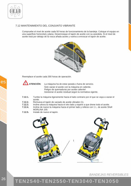
7.12 MANTENIMIENTO DEL CONJUNTO VIBRANTE
Compruebe el nivel de aceite cada 50 horas de funcionamiento de la bandeja. Coloque el equipo en una superficie horizontal y plana. Desenrosque el tapón de aceite con su arandela. Si el nivel de aceite está por debajo de la rosca añada aceite y vuelva a enroscar el tapón de aceite.
Reemplace el aceite cada 300 horas de operación.
! ATENCIÓN: La máquina ha de estar parada o fuera de servicio. Solo vaciar el aceite con la máquina en caliente. Peligro de quemaduras por aceite caliente! Gestionar el aceite residual según la normativa vigente. 7.12.1. Tumbe la máquina ligeramente hacia el lado contrario por el que se vaya a vaciar el
aceite. 7.12.2. Remueva el tapón de vaciado de aceite vibrador (1). 7.12.3. Incline ahora la máquina hacia el otro lado y espere a que drene todo el aceite. 7.12.4. Incline de nuevo la máquina hacia el primer lado y rellene con 1 L. de aceite Shell
MORLINA 100. 7.12.5. Instale de nuevo el tapón.
1

BANDEJAS REVERSIBLES 27
es
TEN2540-TEN2550-TEN3040-TEN3050
7.13 MANTENIMIENTO DEL MANDO HIDRÁULICO
Compruebe el nivel del circuito cada mes o cada 250 horas.
7.13.1. Recoja el mástil a posición de fuera de servicio. 7.13.2. Remueva el tapón de control de la carcasa del asidero. 7.13.3. Compruebe que aceite llega hasta el borde inferior del orificio
! ATENCIÓN: La máquina ha de estar parada o fuera de servicio. Para rellenar el circuito
7.13.4. Remueva el tapón superior de la carcasa bombín del asidero (2). 7.13.5. Llevar el asidero a su posición más avanzada. 7.13.6. Rellene por el orificio del bombín con aceite Shell MORLINA 100 y bombee con el
asidero para que baje el aceite. Repetir la operación hasta que se llene de aceite todo el circuito.
7.13.7. Cierre el orificio de control. 7.13.8. Cierre el orificio de llenado.
2

BANDEJAS REVERSIBLES
es
28 TEN2540-TEN2550-TEN3040-TEN3050
7.14 LOCALIZACIÓN Y REPARACIÓN DE AVERÍAS
MOTOR DE GASOLINA No arranca:
- Existe combustible y la bujía no da chispa � Existe electricidad en el cable de alta tensión
� Existe electricidad en el cable de alta tensión � Bujía de encendido puenteada � Depósito de carbón en la bujía de encendido � Cortocircuito debido a una aislamiento deficiente de la bujía de encendido � Separación incorrecta entre electrodos
� No existe electricidad en el cable de alta tensión � Interruptor del botón de detención en cortocircuito � Bobina de encendido defectuosa � Aislamiento del condensador deficiente ó en cortocircuito � Bobina de encendido rota ó en cortocircuito
� Compresión satisfactoria � Combustible incorrecto � Ha entrado agua ó polvo � Filtro de aire deficiente
- Existe combustible y la bujía de encendido da chispa � Compresión deficiente
� Válvula de admisión o escape pegada ó defectuosa � Aro del pistón ó cilindro gastado � Culata del cilindro ó bujía de encendido ajustada incorrectamente � Junta de culata o junta de la bujía de encendido defectuosa
� El embrague bloqueado haciendo que el vibrador gire al intentar arrancar � No existe combustible en el carburador
� Tanque de combustible vacío � La llave de combustible no está correctamente abierta � Filtro de combustible obturado � Orificio de ventilación de aire de la tapa del tanque obturado � Aire retenido en el tubo � Válvula de entrada del carburador pegada
Potencia Nula: - Potencia insuficiente
� Compresión normal y no se observa fallo del encendido � Filtro de aire deficiente � Depósito de carbón en el cilindro � Nivel de combustible en el carburador incorrecto
� Compresión insuficiente � (Vea “Compresión deficiente” más arriba)
� La compresión es correcta pero el encendido es defectuoso � Existe agua en el combustible � La bujía de encendido está sucia � Bobina de encendido defectuosa � La bobina de encendido se cortocircuita a menudo
� Vibrador lleno con exceso de aceite

BANDEJAS REVERSIBLES 29
es
TEN2540-TEN2550-TEN3040-TEN3050
- Motor recalentado � Depósito de carbón en la cámara de combustible o en la lumbrera de escape � Poder calorífico de la bujía de encendido incorrecto � Aletas de enfriamiento sucias
- La velocidad de rotación fluctúa � Ajuste del regulador incorrecto � Resorte del regulador incorrecto � Flujo de combustible deficiente � Entra aire en el colector de admisión
Función del arrancador de retroceso deficiente - Parte rotativa pegada con polvo - Fallo del resorte helicoidal
MOTOR DIESEL (enfriado por aire)
Arranque deficiente: A.- Compresión deficiente
� Compresión nula � Válvula de succión ó escape defectuosa � Ajuste del sistema de descompresión incorrecto
� Apenas existe compresión o es muy baja � Contacto del asiento de la válvula deficiente � Aro del pistón desgastado � Cilindro gastado � Superficie de ajuste del cilindro y de la culata del cilindro defectuosas � Asiento del inyector flojo
B.- No existe una inyección correcta de combustible en la cámara de combustión
� Flujo de combustible insuficiente ó nulo � Orificio de ventilación de aire en la tapa del tanque obturado � Paso del filtro de combustible obturado y tamiz del filtro obturado � Llave del filtro de combustible cerrada � Aire retenido en el tubo (especialmente cuando el tanque está vacío)
� No existe inyección de combustible en la cámara de combustión � Cilindro de la bomba de inyección ó émbolo pegado � Inyector obturado � Aguja del inyector pegada
� Tanque de combustible vacío � Entró agua o polvo
C.- Sistema de combustible y compresión, etc., normales, sin embargo no arranca
� No alcanzan la velocidad de arranque � Procedimiento de arranque incorrecto � Viscosidad alta o contaminación excesiva del aceite del motor � Aire retenido en el tubo

BANDEJAS REVERSIBLES
es
30 TEN2540-TEN2550-TEN3040-TEN3050
Potencia de salida insuficiente. Compresión deficiente:
� Motor recalentado y escape sucio � Aletas de enfriamiento sucias � Agua en el filtro de combustible � Depósito de carbón en la cámara de combustión en la lumbrera de escape � Ajuste de humo incorrecto � Sobrecarga � Regulación del avance de la inyección incorrecta � Inyector obturado
� La velocidad fluctúa � Contacto incorrecto entre la horquilla del regulador y el manguito � Resorte del regulador incorrecto � Placa de balancín y otras partes deslizantes desgastadas o funcionamiento
defectuoso
� La velocidad del motor no aumenta correctamente � Sincronizado de la válvula incorrecta � Lumbrera de escape o silenciador obturado � Sobrecarga
� Encendido defectuoso acompañado por escape blanco � Pistón, Cilindro, Aro gastado � Inyector obturado � Aro del pistón superior e inferior instalados al revés � Regulación del avance de la inyección incorrecta � Sincronización de la válvula incorrecta Junta de la bomba de inyección floja � Junta de la bomba de inyección floja
� Consumo de combustible alto (Se observa escape oscuro) � Fuga en la tubería de combustible � Elemento de filtro de aire obturado � Combustible defectuoso debido a que contiene impurezas � Sobrecarga
� Parte deslizante excesivamente gastada o aro del pistón pegado � Se está utilizando aceite defectuoso � Se descuida el reemplazo del aceite � Elemento del filtro de aire defectuoso o sucio
� Se detiene súbitamente con un ruido anormal � Engrane o daño del pistón o de la varilla
� Aceite lubricante diluido, aumentando su volumen � Cuerpo del émbolo de bomba de inyección gastado
� El motor no se detiene, aun cuando se interrumpe el suministro de combustible (o causa una sobremarcha)
� Aceite excesivo � Instalación del sistema del regulador incorrecta � Bastidor de la bomba de inyección desplazado

BANDEJAS REVERSIBLES 31
es
TEN2540-TEN2550-TEN3040-TEN3050
OPERACIÓN DE LA MÁQUINA
Se traslada oblicuamente
� Potencia del motor insuficiente � El embrague patina � La correa en V patina � Aceite del vibrador excesivo � Partes internas del vibrador defectuosas
No avanza � Correa en V desacoplada o patina � El embrague patina � Fallo mecánico en la caja de excéntricas: contacte con SAT de Enarco. � Si vibra pero no se traslada, el vibrador puede encontrarse en una
superficie húmeda y deslizante. Pruebe en la superficie correcta
Retroceso a baja velocidad � Falta aceite en el mando hidráulico de la bandeja: rellene con aceite
siguiendo el punto .13. � Aire en el circuito del mando hidráulico: purgue el circuito.
Avance a baja velocidad
� Exceso de aceite en el mando hidráulico: retire aceite del circuito hasta enrasar con el nivel de control.
Fugas de aceite hidráulico � Pérdida de estanqueidad, manguera hidráulica con fallos: sustituya los
componentes defectuosos.

BANDEJAS REVERSIBLES
es
32 TEN2540-TEN2550-TEN3040-TEN3050
8 EN CASO DE AVERÍAS
8.1 INTRUCCIONES PARA PEDIR REPUESTOS
1. En todos los pedidos de repuestos DEBE INCLUIRSE EL CÓDIGO DE LA PIEZA SEGÚN LA LISTA DE PIEZAS. Es recomendable incluir el NÚMERO DE FABRICACIÓN DE LA MÁQUINA.
2. La placa de identificación con los números de serie y modelo se encuentran en la parte superior de la base motor.
3. Provéanos con las instrucciones de transporte correctas, incluyendo la ruta preferida, la dirección y nombre completo del consignatario.
4. No devuelva repuestos a fábrica a menos que tenga permiso por escrito de la misma, todas las devoluciones autorizadas deben enviarse a portes pagados.
8.2 INTRUCCIONES PARA SOLICITAR GARANTÍAS
1. La garantía tiene validez por 1 año a partir de la compra de la máquina. La garantía cubrirá las piezas con defecto de fabricación.
2. En ningún caso la garantía cubrirá una avería por mal uso del equipo. 3. En todas las solicitudes de garantía DEBE ENVIARSE LA MÁQUINA A ENARCO, S.A. O
TALLER AUTORIZADO, indicando siempre la dirección y nombre completo del consignatario. 4. El departamento de S.A.T. notificará de inmediato si se acepta la garantía y en el caso de que
se solicite se enviará un informe técnico. 5. No tendrá ningún tipo de garantía cualquier equipo que haya sido previamente manipulado por
personal no vinculado a ENARCO, S.A.

BANDEJAS REVERSIBLES 33
es
TEN2540-TEN2550-TEN3040-TEN3050
9 DIRECCIONES DE INTERÉS
ENARCO, S.A.
o Dirección: C/ Burtina, 16 50197 ZARAGOZA, SPAIN
o Teléfono: (34) 976 464 090 o Fax: (34) 976 471 470
PÁGINA WEB: http://www.enar.es SERVICIO ATENCIÓN TÉCNICA: [email protected]
NOTA: ENARCO, S.A. se reserva el derecho a modificar cualquier dato de este manual sin previo aviso

REVERSIBLE PLATE COMPACTORS 1
en
TEN2540-TEN2550-TEN3040-TEN3050
C NTENT
1 PREFACE 3
2 SAFETY INFORMATION 4 2.1 SAFETY DURING MACHINE OPERATION ................................................. 4 2.2 SAFETY HILE MOTOR IS RUNNING........................................................ 5 2.3 SAFETY DURING SERVICE........................................................................... 5 2.4 LABELS/SIGNS................................................................................................ 6
3 RECYCLING 7
4 TECHNICAL SPECIFICATIONS 8 4.1 CHARACTERISTICS OF THE MOTOR ......................................................... 8 4.2 CHARACTERISTICS OF THE MACHINE ................................................... 8 4.3 MAXIMUM TILT OF THE PLATE DURING OPERATION .......................... 9 4.4 SOUND AND VIBRATION MEASUREMENTS ............................................ 9
5 OPERATING INSTRUCTIONS 10 5.1 DESCRIPTION OF OPERATION/FUNCTIONS........................................... 10 5.2 APPLICATIONS............................................................................................. 10 5.3 MACHINE TRANSPORT............................................................................... 12
6 OPERATION 14 6.1 BEFORE STARTING OR ......................................................................... 14 6.2 STARTUP ....................................................................................................... 14 6.3 OR ............................................................................................................. 15 6.4 STOPPING THE MOTOR .............................................................................. 16
7 MAINTENANCE 17 7.1 MAINTENANCE SCHEDULE ...................................................................... 17 7.2 CHARACTERISTICS OF THE SPAR PLUG AND SERVICE
(HONDA / ROBIN MOTOR). ......................................................................... 18 7.3 MAINTENANCE OF THE AIR FILTER........................................................ 19 7.4 CHANGING THE MOTOR OIL..................................................................... 21 7.5 ADJUSTING MOTOR SPEED ( HONDA / ROBIN ) .................................... 22 7.6 ADJUSTING THE CARBURETTOR (HONDA / ROBIN) ............................ 22 7.7 CLEANING THE SEDIMENT BO L (HONDA / ROBIN) .......................... 23 7.8 CHANGING THE FUEL FILTER ( HATZ MOTOR)..................................... 24

REVERSIBLE PLATE COMPACTORS
en
2 TEN2540-TEN2550-TEN3040-TEN3050
7.9 CLEANING THE OIL FILTER ( HATZ MOTOR)......................................... 24 7.10 CORRECT TENSION AND SPECIFICATIONS FOR THE BELT.............. 25 7.11 CHANGING THE V-BELT........................................................................... 25 7.12 MAINTENANCE OF THE VIBRATING UNIT........................................... 26 7.13 MAINTENANCE OF THE HYDRAULIC CONTROL................................ 27 7.14 LOCATION AND REPAIR OF FAULTS..................................................... 28
8 TROUBLE-SHOOTING: LOCATION AND REPAIR OF FAULTS 32 8.1 INTRUCTIONS FOR ORDERING PARTS.................................................... 32 8.2 INTRUCTIONS FOR REQUESTING GUARANTEES ................................. 32
9 USEFUL ADDRESSES 33

REVERSIBLE PLATE COMPACTORS 3
en
TEN2540-TEN2550-TEN3040-TEN3050
1 PREFACE We would like to thank our customers for the trust placed in the ENAR brand. It is important to read this manual to gain a full understanding of the characteristics and
functions of the compactor. Before commencing work with this machine, or performing maintenance tasks on it, read, digest and observe all the safety instructions included in this manual.
In the event of this manual becoming lost or a further copy required, this can be ordered from
ENARCO or printed out direct from the ENARCO website: http://www.enar.es. Following the correct procedures for maintenance will guarantee the long life and excellent
performance of this equipment. Although this manual provides certain specifications for the motor, we recommend consulting
the instruction manual for the motor for information on maintenance and repairs. If information concerning the operation or maintenance of this machine is required, please
contact the ENARCO customer service by telephone or fax, or by sending an email to [email protected] or through our website in the section entitled Servicio ENAR.

REVERSIBLE PLATE COMPACTORS
en
4 TEN2540-TEN2550-TEN3040-TEN3050
2 SAFET INFORMATION
2.1 SAFETY DURING THE OPERATION OF THE MACHINE
Improper use or maintenance of the equipment may lead to hazardous situations. Read and digest the instructions in this section before starting work with this machine. Machine operators should ensure that they know how to work the equipment safely. All queries should be dealt with by personnel familiar with the machine or else by contacting ENARCO directly.
� The motor gets very hot during operation: leave it to cool down before touching it.
� Never leave the machine unattended during operation.
� The equipment should not be used without adequate protection of the belt cover. Always make sure this is not missing and that it is in good condition.
� Operators should use protective clothing and ear muffs.
� Close off entry to the worksite for all unauthorised personnel.
� Make sure you know how to disconnect the machine before starting up the motor in case you get into difficulties.
� Make sure the machine has stopped before any attempt is made to move it.
� Do not attempt to lift the equipment unaided. Ask for help or use a lifting machine, taking hold of the equipment by the lifting handle incorporated in the assemblysurrounding the compaction plate.
� Do not use the equipment if you are not in good physical shape.
� Store the equipment properly in a clean, dry place whenever it is not going to be used. Fuels and other consumables should be kept in marked containers in accordance with the manufacturer s instructions. All current legislation concerning the storage site should also be complied with.
� Modifications and adaptations: for safety purposes, it is absolutely forbidden to modify or adapt the equipment in any way, including alterations to the number of revolutions of the motor esstablished by the manufacturer, without prior authorisation from ENARCO. ENARCO will be exempt from any liability deriving from failure to comply with this instruction.
!

REVERSIBLE PLATE COMPACTORS 5
en
TEN2540-TEN2550-TEN3040-TEN3050
2.2 SAFETY DURING OPERATION OF THE MACHINE
Owing to their high degree of inflammability, fuels are particularly dangerous. Improper use can cause serious damage to personnel and materials. Always observe the following safety regulations:
� Do not operate the machine inside a building or closed area without adequate ventilation. Failure to comply with this regulation may lead to intoxication from carbon monoxide with loss of consciousness, and even death.
� Before filling the fuel tank, stop the motor and leave it to cool down for a few minutes.
� Smoking is prohibited while the machine is in operation, or being refueled.
� Do not refill the tank near an open flame and remember to always refuel in an area that is well ventilated.
� If the fuel tank is not airtight, it should be replaced immediately, since it could lead to explosions.
� If any fuel is spilt while refueling, spread sand over the area. Change your clothes if any fuel is spilt on them.
� Make sure that the fuel tank is closed properly after refueling.
� Check that there are no cracks or leaks in the pipes or fuel tank.
2.3 SAFETY DURING SERVICE
� Do not clean or inspect the equipment during operation.
� Do not start the motor up with the cylinder flooded or if the spark plug in the petrol motors has been removed.
� Do not inspect the igniter plug to see if it is sparking correctly if the cylinder is flooded with petrol or in the presence of any petrol fumes.
� Do not use dissolvents or fuels to clean the equipment, particularly in closed spaces.
� Maintain the area around the silencer clear of inflammable materials.
� Before servicing petrol-driven machines, remove the spark plug to guard against the motor starting up accidentally.
� It is not permitted to use the equipment in explosive environments. The fuel tank should be shut tight. When being transported over long distances, it is highly recommended that the fuel tank be emptied beforehand.
� The transport accessory has not been designed for standing the compaction plate on it and should only be used to move the equipment.
!
REVERSIBLE PLATE COMPACTORS
en
6 TEN2540-TEN2550-TEN3040-TEN3050
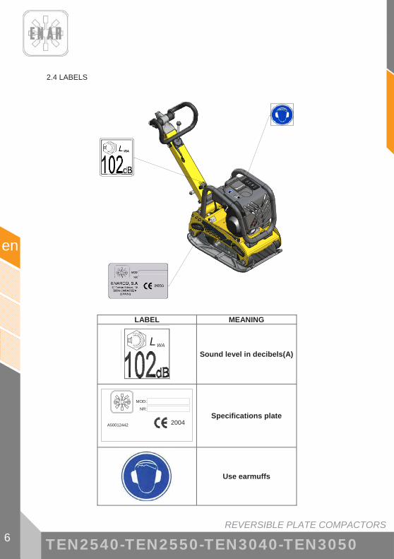
2.4 LABELS
LABEL MEANING
L WA
Sound level in decibels(A)
2004 A50012442
MOD:
NR:
Specifications plate
Use earmuffs

REVERSIBLE PLATE COMPACTORS 7
en
TEN2540-TEN2550-TEN3040-TEN3050
3 REC CLING
To help protect the environment, take the machine to a suitable recycling centre.
COMPONENT MATERIAL Handlebar Steel Cage assembly Steel Engine plate Steel Compaction plate Steel Handlebar cover Rubber Handle supports Aluminium Motor Aluminium Dampers Steel and Rubber Belt Rubber Frame Aluminium Cam box Steel Wheelbase Steel Wheels Plastic and RubberShafts Steel

REVERSIBLE PLATE COMPACTORS
en
8 TEN2540-TEN2550-TEN3040-TEN3050
4 TECHNICAL SPECIFICATIONS
4.1 ENGINE SPECIFICATONS
HATZ 1B20 ROBIN EX 17 HONDA GX160
FUEL Diesel Unleaded petrol (3.6 l)
Unleaded petrol (3.6 l)
ENGINE OIL SAE 10W/40 (0.9 l) SAE 10W/40 (0.6 l) SAE 10W/40 (0.6 l)
NOMINAL PO ER 3.4 kW (4.6 HP) at 3000 rpm
4.2 kW (5.7 HP) at 3600 rpm
4 kW (5.4 HP) at 3600 rpm
SPAR PLUG ------ NGK BPR6ES DENSO W20EPR-U
GAP ------ 0.7 mm - 0.8 mm REVOLUTIONS 3000 ± 100 3600 ± 100
IDLING 1100150200
�� r.p.m. 1400
150200
�� r.p.m.
AIR FILTER DUAL ELEMENT DUAL ELEMENT
4.2 CHARACTERISTICS OF THE MACHINE
CHARACTERÍSTICS MODEL UNIT TEN2540GH TEN2550GH TEN2540DH TEN2550DH TEN2540GR TEN2550GR CENTRIFUGAL FORCE kN 25
OPERATING IDTH mm 400 500 400 500 400 500 FREQUENC Hz.(r.p.m.) 90 (5400) 90 (5400) 85 (5300) 85 (5300) 90 (5400) 90 (5400)
DISPLACEMENT m/min 0-22 0-22 0-20 0-20 0-22 0-22 EIGHT Kg 134 140 148 155 134 140
MOTOR HONDA GX160 HATZ 1B20 ROBIN EX17 VIBRATOR OIL c.c. 1000 (SAE 100)
CHARACTERÍSTICS MODEL
UNIT TEN3040GH TEN3050GH TEN3040DH TEN3050DH TEN3040GR TEN3050GR CENTRÍFUGAL FORCE kN 30
OPERATING IDTH mm 400 500 400 500 400 500 FREQUENC Hz.(r.p.m.) 90 (5400) 90 (5400) 85 (5300) 85 (5300) 90 (5400) 90 (5400)
DISPLACEMENT m/min 0-22 0-22 0-20 0-20 0-22 0-22 EIGHT Kg 134 140 148 155 134 140
MOTOR HONDA GX160 HATZ 1B20 ROBIN EX17 VIBRATOR OIL c.c. 1000 (SAE 100)

REVERSIBLE PLATE COMPACTORS 9
en
TEN2540-TEN2550-TEN3040-TEN3050
658
348
686
1171
935
4.3 MAXIMUM TILT OF THE PLATE DURING OPERATION
20°
4.4 SOUND AND VIBRATION MEASUREMENTS
- Level of acoustic power according to ISO standard 3744: LWA ≈ 102 dB(A)
- Level of acoustic pressure according to ISO standard 6081: LpA ≈ 93 dB(A)
- Weighted real value of axial acceleration according to ISO standard 8662 Part 1: 5 - 10 m/s2
500
400
1094
20°

REVERSIBLE PLATE COMPACTORS
en
10 TEN2540-TEN2550-TEN3040-TEN3050
5 OPERATING INSTRUCTIONS
5.1 DESCRIPTION OF FUNCTIONS
The vibration of the machine is generated by rotating cams in the vibrating unit, which is anchored to the base of the compaction plate. The cams are arranged on two contrarotating shafts. By varying the difference between the contrarotating cams, we can modify the composition of the force generated in the exciter and therefore the direction of oscillation. In this way it is possible to make the machine advance, remain in the same place or go backwards. This action is regulated in a constant, progressive manner using the hydraulic control located in the head of the steering column. The vibrating unit is activated by the machine s thermal motor, which is bolted to the engine plate. The torque generated by the motor is transmitted to the vibrating unit by the centrifugal clutch to the motor outlet and the V-belt connecting the two shafts. At low revolutions the centrifugal clutch is not activated, and therefore it is possible to start up the motor without a load and leave the machine running with the motor ticking over gently. Although the motor s rotation regime can be regulated by means of the accelerator lever, the motor needs to be on maximum regime to avoid the clutch slipping. The underside of the compaction plate is connected to the engine plate by means of four dampers that reduce the vibrations in the upper part of the machine, thereby facilitating operations both for the user and for the machine itself. With the handlebar turned to the furthest position, the plate moves forward at maximum speed. When it is moved backwards, the handlebar reduces the speed of the machine until it comes to a standstill. If the handlebar continues to be pulled back, the compaction plate will start to travel in reverse, until it reaches the limit of the handlebar, at which point the machine is moving in reverse at maximum speed.
5.2 APPLICATIONS
This plate compactor is suitable for compacting granular soils, gravel and cobblestones.Plates fitted with a sprinkler can be used for compacting asphalt surfaces.
Typical applications for compacting soils with granular landfill in water mains, telephone networks, ditches of average or normal width, around pipelines, foundations and paths or pavements for pedestrians and bicylces.
Applications for compacting asphalt surfaces include patching and repairing potholes in the road.

REVERSIBLE PLATE COMPACTORS 11
en
TEN2540-TEN2550-TEN3040-TEN3050
MODEL
APPLICATION
Reversible plates
Non-reversible plates
Rammers
Patching areas �� � ��Building foundations � � �Roads and paths �� � �Courts for tennis and other sports �� � �Preparation of ground � �� ��Final support for bridges or ramps � � ��Level crossings � � ��Interleaved blocks of cement �� � �Network construction � �� �Construction of drainage systems � � �Ditch compaction � � �Hole-repairs due to burst pipes, broken cables, etc. �� �� ��
Around pipelines, cables, drainage systems, etc.
�� �� ��
Landfill with rocks � � �Gravel � � �Sand or volcanic material � � ��Mixed soils � �� �Sludge � � �Clay � � �Thickness of layer 0 – 25 cm � � �Thickness of layer 20 – 40 cm � � �Warm mixture �� � ��Cold mixture �� � ��Base – tack coat 40 – 100 mm � �� �Wearing course 25 – 60 mm �� � �
� Recommended � May be used � Not recommended

REVERSIBLE PLATE COMPACTORS
en
12 TEN2540-TEN2550-TEN3040-TEN3050
5.3 TRANSPORTING THE MACHINE
� Before transporting the compacting machine, proceed as described in point fdffdfd.
� Anchor the mast in position so that it cannot move. Never use the mast to lift the machine.
� Moving the compactor short distances or lifting it on to a van should be done by two people taking hold of the plate by means of the transport handles.
� To hoist the machine using mechanical means:
o Check that the lifting equipment has sufficient capacity to raise the machine (see point 4.2 CHARACTERISTICS OF THE MACHINE).
o Attach the lifting hook or sling to the anchorage point on the machine cage assembly as indicated in the following diagram.
o Never stand underneath a suspended load.
� The loading ramps should be solid and stable. Care should be taken not to place people in danger due to the possiblity of the equipment overturning or sliding, or parts of it knocking against something above or below it.
� To transport the machine inside a vehicle:
o Let the motor cool down
o Shut off the flow of fuel and keep the motor upright so as to avoid any fuel spillage.
o Tie the compactor to the vehicle so as to stop it sliding or overturning.

REVERSIBLE PLATE COMPACTORS 13
en
TEN2540-TEN2550-TEN3040-TEN3050
� To move the machines along the ground: o Secure the guide pole with its anchor device. Place the wheel unit accessory
BS2549 on the front of the machine, with the fastening latches open, facing the anchor points.
o Place the two fastening latches so that the wheel unit is firmly anchored to the machine.
o Tilt the machine forward using the handle and with your foot on the central bar of the wheel unit (A) and move the tray (B).
(A) (B) (C)
W
When you let the machine go, do so gently, keeping your foot on the central bar to keep your balance and so as not to damage the plate (C).
!

REVERSIBLE PLATE COMPACTORS
en
14 TEN2540-TEN2550-TEN3040-TEN3050
6 OPERATION
6.1 BEFORE COMMENCING WORK
6.1.1. Clean off all the dirt, mud, etc. from the unit before commencing work. Special ATTENTION should be paid to the underside of the vibrating plate and the areas adjacent to the air coolant intake for the motor, the carburettor and the air filter. 6.1.2. Check all the screws and make sure that they are tightened properly. Loose screws can
damage the machine. 6.1.3. Check the tension in the V-belt. Normal oscillation should be 10 – 15 mm (1/2”) when
pressure is applied to the belts halfway between the two pulleys. If there is too much play in the belts, there may be a lack of impact or uncontrolled vibration, causing damage to the machine.
6.1.4. The state of the air filter. 6.1.5. Check the oil level in the motor, and if low, top it up. The motor has a 0.6 l oil capacity.
SAE10W/40 engine oil should be used. 6.1.6. Make sure that the compaction plate is level during inspection. The oil level in the vibrator
should reach the level of the stopper. Change the oil once a month or after every 200 hours work. The vibrator has a 120 cc capacity.
IMPORTANT USE SAE 0W/40 OIL Change the oil while it is hot. In order to make it easier for the used oil to come out, tilt the machine and tap the vibrator. 6.1.7. Normal unleaded petrol should be used in the motor. When re-filling the petrol tank,
make sure the filter is in use.
6.2 STARTUP
- HONDA GX160 / ROBIN EX17 MOTOR
6.2.1. Open the fuel cock by moving the lever to the half-open position. In order to start up the motor when it is cold, move the lever for regulating the air to the closed position. When the motor is hot, the air regulator should be either half or completely open. If it is difficult to start the motor up, make sure that the lever for regulating the air is half open to stop the carburettor from flooding due to an excessive amount of fuel.
6.2.2. When pulling on the ignition cord, do not pull it all the way, since this could damage the recuperator spring. Do not let go of the cord suddenly to repeat the startup procedure once the motor has been ignited: keep hold of the handle and slowly let go until it retracts completely.
6.2.3. After starting up the motor, gradually open up the air control lever again. Leave the motor to warm up at minimum speed for 3-5 minutes. This procedure for warming up the motor with minimum revolutions is particularly important during the cold season. While the motor is warming up, the machine should be given a general inspection to detect any anomalies.

REVERSIBLE PLATE COMPACTORS 15
en
TEN2540-TEN2550-TEN3040-TEN3050
- HATZ 1B20 MOTOR
6.2.4. Move the OPEN/ CLOSE fuel lever entirely to the right, so as to let the fuel flow through. 6.2.5. First of all, move the lever for adjusting the revolutions to the STOP position. 6.2.6. Move the lever for adjusting the revolutions to the 1/2 START position or else to the
START position, according to whichever one is considered to be more convenient. Starting up the machine at low revolutions will help reduce the exhaust fumes.
6.2.7. Pull on the ignition cable by means of the handle until a slight resistance is noted. Let the cable return to its position: this will enable the entire length of the cable to be used for starting up the motor.
6.2.8. Hold the handle in both hands. Begin by pulling firmly and increasingly faster on the ignition cable until the motor starts up.
6.2.9. Repeat this procedure until the motor starts up. 6.2.10. If, after several attempts to start the motor, white smoke begins to come out of the
exhaust, move the speed control lever to the STOP position and pull on the ignition cable slowly 5 times. Repeat the startup procedure.
6.3 WORK
6.3.1. The throttle, located on the handle, controls the work of the compactor. Activate the throttle from the idling position until the accelerator reaches full throttle. When the speed of the motor reaches approximately 2,300 r.p.m., the centrifugal clutch should be engaged. If the speed of the motor increases really slowly, it may be due to the clutch slipping. Do not activate the throttle too slowly. IMPORTANT: At the moment when the centrifugal clutch reaches the cutting speed, vibration begins in the cam box.
6.3.2. While working with the compactor, care should be taken not to activate the anchoring ratchet on the handlebar.
6.3.3. For the compaction of asphalt, it is advisable to impregnate the underside of the vibrating plate with diesel fuel. This will help prevent the plate from sticking to the asphalt.
6.3.4. For the compaction of cobblestones, the damper (reference ENARCO C0028) should be used to avoid causing damage to the cobblestones.
6.3.5. In order to suppress the vibrations, move the lever swiftly from ON to OFF. 6.3.6. WORKING ON SLOPES
� For the compaction of soils on a slope, the operator should always stand on higher ground than the machine.
� It is not permitted to operate the machine on slopes with a gradient above the maximum capacity of the machine, as indicated on the technical specifications plate.
� When working on slopes, be extremely careful and always work up or down the slope, never partly or completely sideways on.
� Always begin working from the bottom of the slope. � Damp or excessively loose soils stop the compaction plate from holding firmly,
which increases the risk of accident. 6.3.7. When going backwards, the operator should stand to one side of the equipment to avoid
being trapped between the equipment and an obstacle. Where this is not possible, for instance, in narrow ditches, extreme care should be taken to guard against becoming trapped or losing control of the machine.
6.3.8. Extreme care should be taken in compacting uneven ground or with thick materials. The operator should stand on safe, firm ground.

REVERSIBLE PLATE COMPACTORS
en
16 TEN2540-TEN2550-TEN3040-TEN3050
6.4 STOPPING THE MOTOR
- HONDA GX160 / ROBIN EX17 MOTOR
6.4.1. Before stopping the motor, leave it idling for 2-3 minutes and then press the stop button on the mast of the compactor until the motor comes to a complete standstill.
6.4.2. Shut off the fuel.
- HATZ 1B20 MOTOR
6.4.3. To stop the motor, move the throttle to the idling position, then press the red stop button until the motor stops. Check that when released, the button returns to its original position.
6.4.4. Shut off the flow of fuel by moving the OPEN/CLOSE lever for the carburettor to the left.

REVERSIBLE PLATE COMPACTORS 17
en
TEN2540-TEN2550-TEN3040-TEN3050
7 MAINTENANCE
7.1 MAINTENANCE SCHEDULE
Intervals Maintenance area Maintenance tas s Point
Motor - Check oil level - Inspect air filter
7.4 7.3
Hatz motor - Check water separator Once a day or every 8
hours Machine
- Check for damage, leaks, or similar problems - Clean underside of vibrating plate.
Motor - Change engine oil - Check threaded connections - Clean air filter
7.4
7.3
Hatz motor - Check and adjust valve clearance
After first 20 hours
Machine - Inspect and adjust V-belt 7.10
Motor - Check threaded connections - Cleaning cooling system
Once a ee or every 50
hours Machine - Inspect rubber buffers - Check oil level for vibrator - Inspect and adjust V-belt
7.12
Motor - Change engine oil 7.4
Hatz motor - Clean grating on exhaust - Check and adjust valve clearance
Honda / Robin motor - Clean sediment bowl - Inspect spark plug
7.7 7.2
Monthly or every 250
hours
Machine - Check and tighten up screws - Hydraulic control: check level and top up as
necessary.
7.13
Hatz motor - Change fuel filtration element 7.8 Once every six months or every 500
hours Honda / Robin motor
- Check and adjust setting for carburettor - Inspect and adjust valve clearance - Change vibrator oil
7.6
7.12
Hatz motor - Clean oil filter 7.9
Honda / Robin motor - Clean combustion chamber - Clean fuel tank and filter - Inspect fuel pipe
Once a year or every
1000 hours
Machine - Remove dirt and used grease and replace rusty
components

REVERSIBLE PLATE COMPACTORS
en
18 TEN2540-TEN2550-TEN3040-TEN3050
Storage: When the compactor is to be stored for a lengthy period of time: A. - Completely empty out the fuel from the tan , the fuel pipe and the carburettor B. - Remove the spar plug and pour a fe drops of engine oil in the cylinder. Turn the motor several times by hand to distribute the oil over the inner surface of the cylinder. C. - Clean the outer surface ith a cloth soa ed in oil, cover the unit and eep in a place that is free of dust and damp.
7.2 CHARACTERISTICS OF THE SPARK PLUG AND SERVICE (HONDA / ROBIN MOTOR).
Apart from the weekly maintenance prescribed in the maintenance schedule, clean or replace the spark plug whenever necessary so that the motor can work properly. Instructions for doing this are provided in the manual with explanations on the motor supplied with the compactor. Consult point 4.1 ENGINE SPECIFICATONS to select the spark plug and ascertain the gap required. 7.2.1. Remove the cover from the spark plug and use a suitable plug spanner to extract the
spark plug. 7.2.2. Look at the spark plug to see if it needs replacing due to wear and tear or if the insulator
is split or cracked. 7.2.3. If the spark plug is correct, clean it with a wire brush. 7.2.4. Check that the gap is between 0.7 and 0.8 mm.
0.7 – 0.8 mm
7.2.5. Check that the washer on the spark plug is in good condition and put the spark plug
back by hand so as not to distort the thread. 7.2.6. Then tighten up with the plug spanner to compress the washer.
When fitting a new spark plug, give it a 1/2 turn once it is in place. If the spark plug has been used already, tighten with 1/8 to 1/4 of a turn after placing it in position. PRECAUTION: the spark plug should be really tight, otherwise will heat up and may damage the motor.

REVERSIBLE PLATE COMPACTORS 19
en
TEN2540-TEN2550-TEN3040-TEN3050
!
7.3 MAINTENANCE OF THE AIR FILTER
A dirty air filter can cause the carburettor to malfunction. Clean the filter on a regular basis and more frequently if a lot of dust forms while the machine is working. PRECAUTION: Never use the motor without the air filter, since this will cause a lot of wear and tear to the motor.
Never clean the filter elements of the motor with fuels or solvents with a low flash point, since these could cause an explosion or fire.
HONDA / ROBIN MOTOR: 7.3.1. Unscrew the wing nut and remove the cover from the air filter. Remove the elements,
check them and replace if there are any holes or cracks in them. 7.3.2. Foam element: wash with a soapy solution and rinse thoroughly in clean water.
Alternatively, it can also be washed with non-flammable solvents. Leave it to dry out. Soak the element in clean engine oil and squeeze out the excess oil.
7.3.3. Paper element: tap several times against a hard surface to get rid of the excess dirt, or else apply compressed air from the inside, spraying outwards.
7.3.4. Re-assemble the cartridge using the same procedure in reverse.
Honda GX160 motor filter Robin EX17 motor filter
WING NUT
AIR FILTER
COVER
PAPER
ELEMENT
FOAM ELEMENT

REVERSIBLE PLATE COMPACTORS
en
20 TEN2540-TEN2550-TEN3040-TEN3050
Hatz motor
7.3.5. Remove the screw from the filter cover. 7.3.6. Remove the filter cartridge from the air filter housing. Shake it or blow it with low
pressure. 7.3.7. Replace the filter. 7.3.8. Put the cover back on the housing and screw back into position.
! PRECAUTION:
� Where it is not possible to clean the filter satisfactorily using this procedure (eg. wet or greasy dirt), a new filter cartridge should be inserted instead.
� Ensure that the gasket on the cartridge is not damaged. � Check there are no cracks in the filter cartridge or any other type of damage in
the paper filter, by placing up against the light or shedding light on it from another source.

REVERSIBLE PLATE COMPACTORS 21
en
TEN2540-TEN2550-TEN3040-TEN3050
7.4 CHANGING THE ENGINE OIL
7.4.1. THE MOTOR SHOULD BE LEVEL AND STOPPED. 7.4.2. Drain the oil while the motor is still warm to help it empty out quickly and completely. 7.4.3. Place a receptacle underneath the motor to collect the oil.
HONDA MOTOR :
7.4.4. Unscrew the filler plug and the drainage plug and empty out into a receptacle. 7.4.5. Screw the drainage plug up tightly. 7.4.6. Pour the recommended oil in until it reaches the level (see point 4.1 ENGINE
SPECIFICATONS) 7.4.7. Screw the filler plug tightly into place.
TAPÓN DE ACEITE/ VARILLA INDICADORA
NIVEL TAPÓN DE DRENAJE
Honda/Robin motor HATZ MOTOR:
7.4.8. Place a receptacle underneath the motor to collect the oil. 7.4.9. Remove the drain plug and wait until all the oil has drained out. 7.4.10. Clean the drain plug, fit a new washer and tighten up again (50Nm). 7.4.11. Add engine oil. (see section on technical specifications)
Hatz motor
! PRECAUTION: Use current standard procedures for managing the residual oil. To check the oil level, remove the dipstick, clean off, replace screwing back the plug and finally take it out again and check the level on the dipstick. Where necessary, refill up to the maximum level.
OIL PLUG / DIPSTIC
DRAINAGE PLUG LEVEL
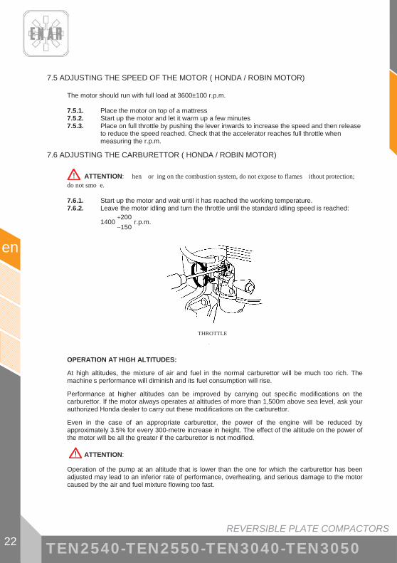
REVERSIBLE PLATE COMPACTORS
en
22 TEN2540-TEN2550-TEN3040-TEN3050
7.5 ADJUSTING THE SPEED OF THE MOTOR ( HONDA / ROBIN MOTOR)
The motor should run with full load at 3600±100 r.p.m. 7.5.1. Place the motor on top of a mattress 7.5.2. Start up the motor and let it warm up a few minutes 7.5.3. Place on full throttle by pushing the lever inwards to increase the speed and then release
to reduce the speed reached. Check that the accelerator reaches full throttle when measuring the r.p.m.
7.6 ADJUSTING THE CARBURETTOR ( HONDA / ROBIN MOTOR)
! ATTENTION: hen or ing on the combustion system, do not expose to flames ithout protection; do not smo e. 7.6.1. Start up the motor and wait until it has reached the working temperature. 7.6.2. Leave the motor idling and turn the throttle until the standard idling speed is reached:
1400150200
��
r.p.m.
TORNILLO DE TOPE DEL ACELERADOR
OPERATION AT HIGH ALTITUDES:
At high altitudes, the mixture of air and fuel in the normal carburettor will be much too rich. The machine s performance will diminish and its fuel consumption will rise.
Performance at higher altitudes can be improved by carrying out specific modifications on the carburettor. If the motor always operates at altitudes of more than 1,500m above sea level, ask your authorized Honda dealer to carry out these modifications on the carburettor.
Even in the case of an appropriate carburettor, the power of the engine will be reduced by approximately 3.5% for every 300-metre increase in height. The effect of the altitude on the power of the motor will be all the greater if the carburettor is not modified.
! ATTENTION:
Operation of the pump at an altitude that is lower than the one for which the carburettor has been adjusted may lead to an inferior rate of performance, overheating, and serious damage to the motor caused by the air and fuel mixture flowing too fast.
THROTTLE
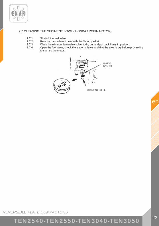
REVERSIBLE PLATE COMPACTORS 23
en
TEN2540-TEN2550-TEN3040-TEN3050
7.7 CLEANING THE SEDIMENT BOWL ( HONDA / ROBIN MOTOR)
7.7.1. Shut off the fuel valve. 7.7.2. Remove the sediment bowl with the O-ring gasket. 7.7.3. Wash them in non-flammable solvent, dry out and put back firmly in position. 7.7.4. Open the fuel valve, check there are no leaks and that the area is dry before proceeding
to start up the motor.
JUNTA TÓRICA
TAPA DE SEDIMENTOS
O-RING GAS ET
SEDIMENT BO L

REVERSIBLE PLATE COMPACTORS
en
24 TEN2540-TEN2550-TEN3040-TEN3050
7.8 CHANGING THE FUEL FILTER (HATZ MOTOR)
The maintenance intervals for the fuel pump filter depend on the purity of the diesel fuel that is used. Where necessary, the interval should be reduced to 250 hours. ! ATTENTION:
� When working on the combustion system, never expose it to naked flames without any protection; do not smoke.
! IMPORTANT: � Make sure that jobs are carried out cleanly, so as to avoid any dirt from entering the
fuel pipe. � Fuel particles may cause damage to the injection system.
7.8.1. Take the cover off the tank and remove the fuel filter from its housing inside the tank, with the aid of the cord.
7.8.2. Unscrew fuel pipe “1” from filter “2” and fit a new filter. 7.8.3. Fit the filter back in place and replace the cover on the fuel tank. 7.8.4. The fuel injection system will commence purging automatically.
7.9 CLEANING THE OIL FILTER (HATZ MOTOR)
The oil filter should be cleaned at the same time as the oil is changed, since there may be a loss of oil when this filter is changed.
! ATTENTION: � The motor should remain at a standstill and in a horizontal position. � Danger of burns caused by hot oil! � Use current standard procedures for managing the residual oil.
7.9.1. Loosen nut “1” (approximately 5 turns). 7.9.2. Remove the filter from its housing. 7.9.3. Use compressed air from the inside spraying outwards to eliminate dirt from the filter. 7.9.4. Check the state of gasket “1”, and replace if damaged. 7.9.5. Check that gasket “2” is in good condition and inserted in the correct position, if
necessary, change the oil filter. 7.9.6. Lubricate the gasket before fitting in position. 7.9.7. Insert the filter and press home. 7.9.8. Make sure that ends “1” of the tension springs are next to the oil filter before tightening
up the nut. 7.9.9. Check the oil level with the dipstick and, if necessary, fill up with oil until it reaches the
MAX level.

REVERSIBLE PLATE COMPACTORS 25
en
TEN2540-TEN2550-TEN3040-TEN3050
7.10 CORRECT TENSION AND SPECIFICATION OF THE BELT
Check the tension in the belt when the machine is new or when it has been replaced and during the next five hours when the compactor is in service. When the machine is working normally, check and adjust as necessary after every 50 hours service or on a weekly basis. Tightening the belt: the belt can be tightened by means of the cams for adjusting the distance between the compaction plate and that of the motor.
TENSADO MÁXIMO TENSADO MÁXIMO
TENSADO MÍNIMO TENSADO MÍNIMO
7.10.1. Unscrew the three lockscrews on the top belt cover and remove. 7.10.2. Loosen the lockscrews for the adjustment cams. 7.10.3. Place the cams in such a way that when they are all in the same position the belt is
tightened so that when a small amount of pressure is exerted on it in the middle it flexes 10-15 mm.
7.10.4. Tighten up the four lockscrews again on the adjustment cams. 7.10.5. Replace the upper belt cover and tighten up the two screws for the cover.
7.11 CHANGING THE V-BELT
! ATTENTION: The machine should be stopped or out of service.
! If the machine had been working, the transmission unit will be hot. Check that the machine has cooled down before carrying out this operation.
7.11.1. Loosen the screws on the upper (1) and lower (2) belt cover and remove the belt covers. 7.11.2. Adjust the cams to the minimum tension position so that the belt can be removed easily
(4). 7.11.3. Remove the belt and fit a new one. The belt specification for the Honda GX160 motor is
B (17× 11) 930 and for the 1B20 motor is B (17× 11) 910. 7.11.4. Adjust the cams so that when pressed lightly in the centre, the belt will flex 10-15 mm 7.11.5. ! ATTENTION: Check that the 4 tension plates remain in the same position to
ensure that the machine is well-balanced. 7.11.6. Replace the upper and lower belt covers.
MAXIMUM TENSION
MINIMUM TENSION
DISPLACEMENT 10-15 mm

REVERSIBLE PLATE COMPACTORS
en
26 TEN2540-TEN2550-TEN3040-TEN3050
7.12 MAINTENANCE OF THE VIBRATING UNIT
Check the oil level after every 50 hours working with the compactor. Place the equipment on a flat, horizontal surface. Unscrew the oil plug and washer. If the oil level is below the thread, top up with oil and screw the oil plug back into place.
Change the oil after every 300 hours of operation.
! ATTENTION: The machine should be stopped or out of service. Only empty out the oil when the machine is warm. Danger of burns caused by hot oil! Use current standard procedures for managing the residual oil. 7.12.1. Tilt the machine slightly to the opposite side from the one on which the oil is going to be
emptied out. 7.12.2. Remove the drainage plug for the vibrating oil (1). 7.12.3. Now tilt the machine to the other side and wait until all the oil has drained out. 7.12.4. Tilt the machine back the other way and refill with 1 L. of Shell MORLINA 100 oil. 7.12.5. Replace the plug.

REVERSIBLE PLATE COMPACTORS 27
en
TEN2540-TEN2550-TEN3040-TEN3050
7.13 MAINTENANCE OF THE HYDRAULIC CONTROL
Check the level of the circuit once a month or every 250 hours.
7.13.1. Return the mast to the out-of-service position. 7.13.2. Remove the control plug for the handlebar casing. 7.13.3. Check that the oil reaches the inside edge of the hole
! ATTENTION: The machine should be stopped or out of service. To top up the circuit.
7.13.4. Remove the upper plug from the pump housing in the handlebar (2). 7.13.5. Push the handle to its forwardmost position. 7.13.6. Top up through the hole in the oil pump with Shell MORLINA 100 oil and using the
handle, pump to make the oil go down. Repeat this operation until the whole circuit is full of oil.
7.13.7. Close the control port. 7.13.8. Close the fill port.
2

REVERSIBLE PLATE COMPACTORS
en
28 TEN2540-TEN2550-TEN3040-TEN3050
7.14 TROUBLESHOOTING: LOCATION AND REPAIR OF FAULTS
PETROL MOTOR
ill not start: - There is fuel in the tan but the igniter plug ill not spar
� There is electricity in the high-tension cable � There is electricity in the high tension cable � Spar plug shorts out � Carbon deposits on igniter plug � Shortcircuit due to faulty insulation of the igniter plug � Incorrect separation bet een electrodes
� There is no electricity in the high-tension cable � Shortcircuit of stop button s itch � Faulty ignition coil � Faulty insulation or shortcircuit of condenser � Ignition coil bro en or shortcircuiting
� Compaction satisfactory � Incorrect fuel � Water or dust has got inside � Faulty air filter
- There is fuel in the tan and the igniter plug spar s correctly � Incorrect compaction
� Inta e or exhaust valve is stuc or faulty � Piston ring or cylinder is orn � Cylinder head or spar plug not adjusted properly � Head gas et or gas et on spar plug faulty
� The clutch is bloc ed ma ing the vibrator turn hen attempting to start � There is no fuel in the carburettor
� Fuel tan is empty � The fuel coc is not open properly � Fuel filter is bloc ed � Air vent in the tan cover is bloc ed � Air retained in the fuel pipe � Carburettor inta e valve is stuc
No po er:
- Insufficient po er � Compaction normal and no fault observed in the starting mechanism
� Faulty air filter � Carbon deposits in the cylinder � Fuel level in the carburettor is incorrect
� Inadequate compaction � (See “Incorrect compaction” above)
� Compaction is correct but startup is deficient � There is ater in the fuel � The spar plug is dirty � The ignition coil is faulty � The ignition coil often shortcircuits
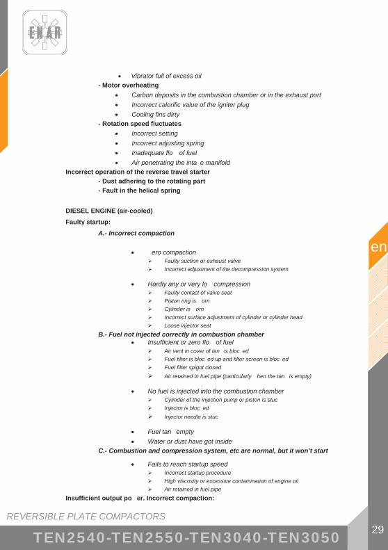
REVERSIBLE PLATE COMPACTORS 29
en
TEN2540-TEN2550-TEN3040-TEN3050
� Vibrator full of excess oil - Motor overheating
� Carbon deposits in the combustion chamber or in the exhaust port � Incorrect calorific value of the igniter plug � Cooling fins dirty
- Rotation speed fluctuates � Incorrect setting � Incorrect adjusting spring � Inadequate flo of fuel � Air penetrating the inta e manifold
Incorrect operation of the reverse travel starter - Dust adhering to the rotating part - Fault in the helical spring
DIESEL ENGINE (air-cooled)
Faulty startup: A.- Incorrect compaction
� ero compaction � Faulty suction or exhaust valve � Incorrect adjustment of the decompression system
� Hardly any or very lo compression � Faulty contact of valve seat � Piston ring is orn � Cylinder is orn � Incorrect surface adjustment of cylinder or cylinder head � Loose injector seat
B.- Fuel not injected correctly in combustion chamber � Insufficient or zero flo of fuel
� Air vent in cover of tan is bloc ed � Fuel filter is bloc ed up and filter screen is bloc ed � Fuel filter spigot closed � Air retained in fuel pipe (particularly hen the tan is empty)
� No fuel is injected into the combustion chamber � Cylinder of the injection pump or piston is stuc � Injector is bloc ed � Injector needle is stuc
� Fuel tan empty � Water or dust have got inside
C.- Combustion and compression system, etc are normal, but it won’t start
� Fails to reach startup speed � Incorrect startup procedure � High viscosity or excessive contamination of engine oil � Air retained in fuel pipe
Insufficient output po er. Incorrect compaction:

REVERSIBLE PLATE COMPACTORS
en
30 TEN2540-TEN2550-TEN3040-TEN3050
� Motor overheating and exhaust dirty � Cooling fins dirty � Water in fuel filter � Carbon deposits in combustion chamber in exhaust port � Incorrect adjustment of fumes � Overload � Incorrect adjustment of injection speed � Injector bloc ed
� Fluctuating speed � Incorrect contact bet een control for and hose � Incorrect adjusting spring � Vibrating arm and other sliding parts orn or not or ing properly
� The motor does not increase speed correctly � Incorrect synchronization of the valve � Exhaust port or silencer bloc ed � Overload
� Defective startup together ith hite exhaust fumes � Piston, Cylinder, Ring orn � Injector bloc ed � pper or lo er piston rings installed the rong ay round � Incorrect setting for injection speed � Incorrect synchronization of the valve � Loose gas et on injection pump
� High fuel consumption (dar exhaust fumes observed) � Lea in fuel pipe � Air filter element bloc ed � Defective fuel due to presence of impurities � Overload
� Sliding element orn out or piston ring stuc � Defective oil is being used � The need to change the oil has been neglected � Air filter element is defective or dirty
� Stops suddenly ith a strange noise � Engagement or damage or the piston or rod
� Diluted lubricating oil, increasing its volume � Body of the injection pump piston is orn
� The motor does not stop, even hen the fuel supply is cut off (or causes overdrive)
� Too much oil � Incorrect installation of adjustment system � Displacement of the injection pump frame

REVERSIBLE PLATE COMPACTORS 31
en
TEN2540-TEN2550-TEN3040-TEN3050
OPERATING THE MACHINE
It moves on the s e
� Insufficient engine capacity � The clutch is slipping � The V belt is slipping � Too much vibrating oil � Internal parts of the vibrator are faulty
It does not advance � V belt uncoupled or slipping � The clutch is slipping � Mechanical fault in the cam box: contact technical department (SAT) at
Enarco. � It vibrates but does not move. The vibrator may be on a slippery, et
surface. Try on the right surface.
Moves bac very slo ly � Lac of oil in the hydraulic control unit for the compactor: top up ith oil
follo ing the instructions given in point .13. � Air in the hydraulic control circuit: purge the circuit.
Moves for ard very slo ly
� Too much oil in the hydraulic control unit: remove oil from the circuit until it reaches the control level.
Hydraulic oil lea s � Loss of oil tightness, fla s in hydraulic hose: replace the faulty
components.

REVERSIBLE PLATE COMPACTORS
en
32 TEN2540-TEN2550-TEN3040-TEN3050
8 IN CASE OF FAILURE
8.1 INTRUCTIONS FOR ORDERING PARTS
1. In all orders placed for parts, THE CODE NO. GIVEN IN THE LIST OF PARTS SHOULD BE INCLUDED FOR THE PART CONCERNED. It is advisable to include the MACHINE S SERIAL NUMBER.
2. The specifications plate with the serial numbers and MODEL are on the top of the engine plate.
3. Please supply the correct instructions for transport, including the preferred route, address and complete name of the consignee.
4. Do not return parts to the factory unless you have been given written permission to do so. All authorized items should be returned carriage paid.
8.2 INTRUCTIONS FOR REQUESTING GUARANTEES
1. The guarantee is valid for one year from the date the machine was purchased. The guarantee covers the parts with manufacturing faults.
2. In no case will the guarantee cover a fault caused by improper use of the equipment. 3. In all requests for guarantees, THE MACHINE SHOULD BE SENT TO ENARCO, S.A. OR AN
AUTHORIZED WORKSHOP, always indicating the complete name and address of the consignee.
4. The Technical Department (S.A.T.) will notify you immediately if the guarantee has been accepted and, if requested, can also send out a technical report.
5. No piece of equipment will be covered by guarantee if it has been manipulated previously by personnel not connected to ENARCO, S.A.

REVERSIBLE PLATE COMPACTORS 33
en
TEN2540-TEN2550-TEN3040-TEN3050
9 USEFUL ADDRESSES
ENARCO, S.A.
o Address: C/ Burtina, 16 50197 ZARAGOZA, SPAIN
o Telephone: (34) 976 464 090 o Fax: (34) 976 471 470
WEBSITE: http://www.enar.es TECHNICAL DEPT: [email protected]
NOTE: ENARCO, S.A. reserves the right to modify any information in this manual without prior notice

PLATEA R VERSIBLES 1
fr
TEN2540-TEN2550-TEN3040-TEN3050
INDE
1 PR FACE 3
2 INFORMATIONS DE S CURIT 4 2.1 S CURIT DANS LA MANIPULATION DE LA MACHINE ............................ 4 2.2 S CURIT DANS LA MANIPULATION DU MOTEUR ............................... 5 2.3 S CURIT DANS LE SERVICE...................................................................... 5 2.4 SIGNALISATIONS .......................................................................................... 6
3 RECYCLAGE 7
4 DONN ES TECHNI UES 8 4.1 DONN ES DU MOTEUR ................................................................................ 8 4.2 DONN ES DE LA MACHINE ......................................................................... 8 4.3 INCLINAISON MAXIMALE DU PLATEAU EN
FONCTIONNEMENT....................................................................................... 9 4.4 MESURES ACOUSTIQUES ET VIBRATOIRES............................................ 9
5 INSTRUCTIONS DE MANIPULATION 10 5.1 DESCRIPTION DU FONCTIONNEMENT ................................................... 10 5.2 APPLICATIONS............................................................................................. 10 5.3 TRANSPORT DE LA MACHINE .................................................................. 12
6 FONCTIONNEMENT 14 6.1 AVANT DE COMMENCER LE TRAVAIL................................................... 14 6.2 MISE EN MARCHE........................................................................................ 14 6.3 TRAVAIL........................................................................................................ 15 6.4 ARR T DU MOTEUR.................................................................................... 16
7 ENTRETIEN 17 7.1 CALENDRIER D ENTRETIEN ..................................................................... 17 7.2 CARACT RISTIQUES DE LA BOUGIE DU MOTEUR ET SERVICE
(HONDA / ROBIN). ........................................................................................ 18 7.3 ENTRETIEN DU FILTRE AIR ................................................................... 19 7.4 VIDANGE DU MOTEUR............................................................................... 21 7.5 R GLAGE DE LA VITESSE DU MOTEUR (MOTEUR HONDA /
ROBIN)............................................................................................................ 22 7.6 R GLAGE DU CARBURATEUR (MOTEUR HONDA / ROBIN) ............... 22

PLATEA R VERSIBLES
fr
2 TEN2540-TEN2550-TEN3040-TEN3050
7.7 NETTOYAGE DU D P T DE S DIMENTS (MOTEUR HONDA / ROBIN)............................................................................................................ 23
7.8 CHANGEMENT DU FILTRE DE COMBUSTIBLE (MOTEUR HATZ) ...... 24 7.9 NETTOYAGE DU FILTRE HUILE (MOTEUR HATZ) ............................ 24 7.10 TENSION CORRECTE ET SP CIFICATION DE LA COURROIE............ 25 7.11 CHANGER LA COURROIE TRAP ZO DALE .......................................... 25 7.12 ENTRETIEN DE L ENSEMBLE VIBRATOIRE......................................... 26 7.13 ENTRETIEN DE LA COMMANDE HYDRAULIQUE ............................... 27 7.14 LOCALISATION ET R PARATION DE PANNES .................................... 28
8 EN CAS DE PANNE 32 8.1 INSTRUCTIONS POUR COMMANDER DES PI CES DE
RECHANGE.................................................................................................... 32 8.2 INSTRUCTIONS POUR FAIRE VALOIR LA GARANTIE.......................... 32
9 ADRESSES UTILES 33
PLATEA R VERSIBLES 3
fr
TEN2540-TEN2550-TEN3040-TEN3050
1 PRÉFACE Nous vous remercions pour la confiance que vous manifestez pour la marque ENAR. La lecture du présent manuel est importante pour la compl te connaissance des
caractéristiques et des opérations de travail du plateau de compactage. Avant de commencer travailler avec cette machine ou d y réaliser des opérations d entretien, lisez, comprenez et respectez les instructions de sécurité de ce manuel.
En cas de perte de ce manuel ou si vous voulez un exemplaire supplémentaire, vous pouvez le
demander ENARCO ou le trouver sous format électronique sur la page web d ENARCO: http://www.enar.es et l imprimer.
Les procédés corrects d entretien garantissent une longue durée de vie et un excellent travail
de l unité. M me si ce manuel fournit quelques indications propos du moteur, pour son entretien et ses
réparations nous recommandons une consultation du manuel d instructions du moteur. Si vous avez besoin d informations au sujet de la manipulation ou de l entretien de cette
machine, mettez-vous en contact avec le service d assistance d ENARCO en appelant par téléphone, en envoyant un fax ou en réalisant une consultation par courrier électronique [email protected] ou travers la page web dans la section Service ENAR.

PLATEA R VERSIBLES
fr
4 TEN2540-TEN2550-TEN3040-TEN3050
2 INFORMATIONS DE SÉCURITÉ
2.1 SÉCURITÉ DANS LA MANIPULATION DE LA MACHINE
Une utilisation ou un entretien incorrects du matériel peuvent entra ner des situations de danger. Lisez et assimilez les instructions de cette section avant de commencer travailler avec cette machine. L opérateur du matériel doit tre responsable et doit savoir travailler en respectant les conditions de sécurité du matériel. Si vous avez des doutes, demandez des
informations des personnes connaissant parfaitement la machine ou mettez-vous en contact avec ENARCO.
� Le moteur chauffe beaucoup pendant son fonctionnement, laissez-le refroidir avant de le toucher.
� Ne laissez jamais la machine en marche sans surveillance.
� Vous ne devez pas utiliser le matériel sans une protection appropriée du couvre-courroie. Vérifiez toujours qu il ne manque pas et qu il est en bon état.
� L ouvrier doit utiliser des v tements de protection et des protecteurs auditifs.
� Interdisez l acc s la zone de travail aux personnes non autorisées.
� Vérifiez que vous savez déconnecter la machine avant de mettre en marche le moteur au cas o vous rencontreriez des difficultés.
� Arr tez la machine avant de la transporter.
� N essayez pas de soulever le matériel sans aide. Demandez de l aide ou servez-vous d un appareil de levage en utilisant le levier intégré la caisse du plateau.
� N utilisez pas le matériel si vous n tes pas en bonne condition physique.
� Emmagasinez le matériel adéquatement dans un lieu propre et sec quand vous ne l utilisez pas. Les combustibles et autres consumables devront tre stockés dans des récipients marqués en suivant les instructions de leurs fabricants. Respectez ainsi les dispositions légales en vigueur dans le lieu de stockage.
� Modifications et adaptations: pour des raisons de sécurité, il est compl tement interdit de réaliser tout type de modification ou d adaptation au matériel, m me de varier le nombre de révolutions du moteur réglé en usine, sans l autorisation préalable d ENARCO. Face toute responsabilité dérivée de l inaccomplissement de cette instruction, ENARCO sera libre de toute obligation.
!

PLATEA R VERSIBLES 5
fr
TEN2540-TEN2550-TEN3040-TEN3050
2.2 SÉCURITÉ DANS LA MANIPULATION DU MOTEUR
cause de sa haute inflammabilité, les combustibles sont particuli rement dangereux. Leur usage inapproprié peut provoquer de graves dég ts personnels et matériels. Respectez toujours les r gles de sécurité suivantes:
� Ne faites pas fonctionner le matériel l intérieur d un b timent ou dans des zones fermées sans une aération adécuate. Dans le cas contraire, vous pouvez tre victime d une intoxication au monoxyde de carbone avec perte de connaissance, pouvant aller m me jusqu la mort.
� Avant de remplir le réservoir de combustible, arr tez le moteur et laissez-le refroidir quelques minutes.
� Vous ne devez pas fumer pendant le fonctionnement de la machine, ni pendant le ravitaillement en carburant.
� Ne remplissez pas le réservoir pr s d une flamme ouverte et remplissez-le dans une zone bien aérée.
� Remplacez immédiatement le réservoir de combustible s il n est pas hermétique, il pourrait provoquer des explosions.
� Si, pendant le ravitaillement, du carburant est déversé, absorbez-le avec du sable. Changez-vous si vous renversez du carburant sur vos v tements.
� Assurez-vous que le réservoir de combustible est bien fermé apr s l avoir rempli.
� Vérifiez que la tuyauterie et le réservoir de combustible n ont ni fissures ni fuites.
2.3 SÉCURITÉ DANS LE SERVICE
� Ne nettoyez pas et ne révisez pas le matériel pendant son fonctionnement.
� Ne faites pas démarrer le moteur avec le cylindre inondé ou en ayant retiré la bougie des moteurs d essence.
� Ne vérifiez pas que la bougie fait des étincelles si le cylindre est inondé d essence ou s il y a des vapeurs d essence.
� N utilisez pas de dissolvants ou de combustibles pour nettoyer le matériel, surtout dans des lieux fermés.
� Maintenez le silencieux dans un périm tre de sécurité loin de matériaux inflammables.
� Avant de faire des opérations de service sur des équipements avec un moteur essence, déplacez la bougie pour éviter un démarrage imprévu du moteur.
� Il n est pas permis d utiliser le matériel dans des atmosph res explosives. Le réservoir de combustible doit fermer hermétiquement. Dans des transports de longue distance il est vivement recommandé de vider de combustible le réservoir du moteur.
� L accessoire de transport n a pas été con u pour qu on y garde le plateau, utilisez-le seulement pour déplacer la machine.
!

PLATEA R VERSIBLES
fr
6 TEN2540-TEN2550-TEN3040-TEN3050
2.4 SIGNALISATIONS
SIGNALISATION SIGNIFICATION
L WA
Niveau de puissance acoustique en dB(A)
2004 A50012442
MOD:
NR:
Plaque d identification
Utilisez des protecteurs auditifs
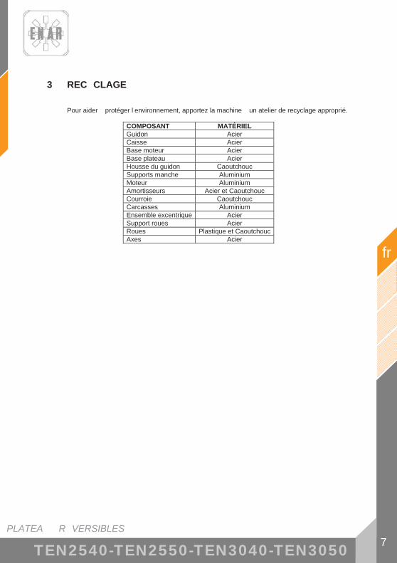
PLATEA R VERSIBLES 7
fr
TEN2540-TEN2550-TEN3040-TEN3050
3 REC CLAGE
Pour aider protéger l environnement, apportez la machine un atelier de recyclage approprié.
COMPOSANT MATÉRIEL Guidon Acier Caisse Acier Base moteur Acier Base plateau Acier Housse du guidon Caoutchouc Supports manche Aluminium Moteur Aluminium Amortisseurs Acier et Caoutchouc Courroie Caoutchouc Carcasses Aluminium Ensemble excentrique Acier Support roues Acier Roues Plastique et CaoutchoucAxes Acier

PLATEA R VERSIBLES
fr
8 TEN2540-TEN2550-TEN3040-TEN3050
4 DONNÉES TECHNIQUES
4.1 DONNÉES DU MOTEUR
HATZ 1B20 ROBIN EX 17 HONDA GX160
COMBUSTIBLE Diesel Essence sans plomb (3,6 l)
Essence sans plomb (3,6 l)
HUILE MOTEUR SAE 10W/40 (0,9 l) SAE 10W/40 (0,6 l) SAE 10W/40 (0,6 l) PUISSANCE NOMINALE
3,4 kW (4,6 HP) 3000 rpm
4,2 kW (5,7 HP) 3600 rpm
4 kW (5,4 HP) 3600 rpm
BOUGIE ------ NGK BPR6ES DENSO W20EPR-U
ENTREFER ------ 0,7 mm - 0,8 mm RÉVOLUTIONS 3000 ± 100 3600 ± 100
RALENTÍ 1100150200
�� r.p.m. 1400
150200
�� r.p.m.
FILTRE AIR ÉLÉMENT DOUBLE ÉLÉMENT DOUBLE
4.2 DONNÉES DE LA MACHINE
CARACTÉRISTIQUES MOD LE UNITÉ TEN2540GH TEN2550GH TEN2540DH TEN2550DH TEN2540GR TEN2550GR
FORCE CENTRÍFUGE kN 25 LARGEUR DE TRAVAIL mm 400 500 400 500 400 500
FRÉQUENCE Hz.(r.p.m.) 90 (5400) 90 (5400) 85 (5300) 85 (5300) 90 (5400) 90 (5400) DÉPLACEMENT m/min 0-22 0-22 0-20 0-20 0-22 0-22
POIDS Kg 134 140 148 155 134 140 MOTEUR HONDA GX160 HATZ 1B20 ROBIN EX17
HUILE VIBRATEUR c.c. 1000 (SAE 100)
CARACTÉRISTIQUES MOD LE UNITÉ TEN3040GH TEN3050GH TEN3040DH TEN3050DH TEN3040GR TEN3050GR
FORCE CENTRÍFUGE kN 30 LARGEUR DE TRAVAIL mm 400 500 400 500 400 500
FRÉQUENCE Hz.(r.p.m.) 90 (5400) 90 (5400) 85 (5300) 85 (5300) 90 (5400) 90 (5400) DÉPLACEMENT m/min 0-22 0-22 0-20 0-20 0-22 0-22
POIDS Kg 134 140 148 155 134 140 MOTEUR HONDA GX160 HATZ 1B20 ROBIN EX17
HUILE VIBRATEUR c.c. 1000 (SAE 100)

PLATEAUX RÉVERSIBLES 9
fr
TEN2540-TEN2550-TEN3040-TEN3050
658
348
686
1171
935
4.3 INCLINAISON MAXIMALE DU PLATEAU EN FONCTIONNEMENT
20°
4.4 MESURES ACOUSTIQUES ET VIBRATOIRES
- Niveau de puissance acoustique selon ISO 3744: LWA ≈ 102 dB(A)
- Niveau de pression sonore selon ISO 6081: LpA ≈ 93 dB(A)
- Valeur effective pondérée d’accélération axiale selon ISO 8662 Partie 1: 5 - 10 m/s2
500
400
1094
20°

PLATEA R VERSIBLES
fr
10 TEN2540-TEN2550-TEN3040-TEN3050
5 INSTRUCTIONS DE MANIPULATION
5.1 DESCRIPTION DU FONCTIONNEMENT
La vibration de la machine est générée gr ce des excentriques rotatoires dans l ensemble vibratoire qui est ancré la base du plateau. Les excentriques sont disposés en deux axes contre rotatifs. En variant le décalage entre les excentriques contre rotatifs, nous modifions la composition de forces générées dans l excitateur et donc la direction des oscillations. Nous pouvons ainsi faire que la machine avance, reste sa place ou recule. Ce réglage se réalise de mani re continue et progressive au moyen de la commande hydraulique située en t te de la barre de direction. L ensemble vibratoire est actionné par le moteur thermique de la machine, qui est rattaché la base moteur travers des boulons. Le couple généré par le moteur est transmis l ensemble vibratoire par l embrayage centrifuge la sortie du moteur et la courroie en V qui raccorde les deux axes. de faibles révolutions, l embrayage centrifuge n a pas d effet, ainsi le moteur peut démarrer sans charge et marcher doucement au ralenti. M me si par le levier de l accélérateur on peut régler le régime de rotation du moteur, on doit mettre le moteur un régime maximum pour que l embrayage ne patine pas. La base inférieure du plateau est reliée la base moteur par quatre amortisseurs qui réduisent les vibrations dans la masse supérieure de la machine, de cette mani re le moteur et l utilisateur peuvent opérer avec plus de sécurité. Avec le manche tourné dans sa position la plus avancée, le plateau avance sa vitesse maximale. mesure que le manche recule, la vitesse de progression de l équipement diminue jusqu ne plus avancer. Si on continue tirer sur le manche, le plateau commence aller vers l arri re. Ainsi quand on arrive la position butoir du manche, la machine recule sa vitesse maximum.
5.2 APPLICATIONS
Ce plateau est approprié au compactage des sols granulaires, gravier et pavés. Les plateaux dotés de rampe d arrosage peuvent tre utilisés pour le compactage d asphalte.
Les applications typiques de compactage des sols sont surtout des remplissages de nappes d eau avec des matériaux granulaires, installations téléphoniques, tranchées de largeur moyenne, zones autour des tuyauteries, fondations et chemins ou trottoirs pour les piétons et les pistes cyclables.
Les applications en compactage d asphalte incluent le rapi cement et la réparation des trous sur les routes.

PLATEA R VERSIBLES 11
fr
TEN2540-TEN2550-TEN3040-TEN3050
MODELO
APLICACIÓN
MOD LE APPLICATION
Plaques réversibles
Plaques non réversibles
Dames
Zones de rapi cement �� � ��Fondation de b timents � � �Chemins et promenades �� � �Terrains de tennis et de sport �� � �Préparation de base � �� ��Support final de ponts ou rampes � � ��Croisement ferroviaire � � ��Blocs de béton entrecroisés �� � �Construction de réseaux � �� �Construction de drainages � � �Compactage de tranchées. � � �Réparation de trous pour cause de rupture de tuyauteries, c bles, etc. �� �� ��
Autour des tuyauteries, c bles, drainages, etc.
�� �� ��
Remplissage de pierres � � �Gravier � � �Sable ou matériel volcanique � � ��Sols mixtes � �� �Boue � � �Argile � � �Épaisseur de couche 0 – 25 cm � � �Épaisseur de couche 20 – 40 cm � � �Mélange chaud �� � ��Mélange froid �� � ��Base - Couche de liaison 40 – 100 � �� �Couche de roulement 25 – 60 mm �� � �
� Recommandé � Peut tre utilisé � Déconseillé

PLATEA R VERSIBLES
fr
12 TEN2540-TEN2550-TEN3040-TEN3050
5.3 TRANSPORT DE LA MACHINE
� Avant de transporter la plaque vibrante, suivez les indications décrites dans le point fdffdfd.
� Bloquez le manche gr ce son point d ancrage. N utilisez jamais le manche pour lever la machine.
� Pour déplacer la plaque vibrante sur de courtes distances ou pour la monter dans une fourgonnette, il faut le faire deux, en saisissant la machine par les poignées de transport.
� Pour la hisser mécaniquement :
o Vérifiez que les appareils de levage disposent d une capacité suffisante pour lever la machine (voir point 4.2 DONNÉES DE LA MACHINE ).
o Mettez le crochet de levage ou l élingue au point d ancrage sur la carcasse de la machine comme il est indiqué dans l illustration suivante.
o Ne vous mettez jamais au-dessous de la charge suspendue.
� Les rampes de chargement doivent tre solides et stables. Il faudra faire attention ne pas mettre en danger des personnes avec de possibles chutes ou glissements de la machine, et ce que des pi ces de la machine ne donnent pas d -coups vers le haut ou vers le bas.
� Pour transporter la machine dans un véhicule:
o Laissez refroidir le moteur
o Fermez le robinet de combustible et maintenez le moteur debout pour éviter de renverser le combustible.
o Attachez la plaque vibrante au véhicule pour éviter les glissements ou la chute

PLATEA R VERSIBLES 13
fr
TEN2540-TEN2550-TEN3040-TEN3050
� Pour déplacer la machine sur le sol : o Fixez le manche de guidage son point d ancrage. Placez le syst me ensemble-
roues BW2549 sur le devant de la machine avec les cliquets de fixation ouverts orientés vers les points d ancrage.
o Appuyez sur les deux cliquets de fixation de sorte que l ensemble-roues soit fermement ancré la machine.
o Inclinez avec le manche la machine vers l avant en vous aidant du pied sur la barre centrale de l ensemble roues (A) et déplacez le plateau (B).
(A) (B) (C)
Quand vous l chez la machine, faites-le en douceur, en appuyant le pied sur le marchepied pour ne pas tre projeté et pour ne pas endommager le plateau (C).
!

PLATEA R VERSIBLES
fr
14 TEN2540-TEN2550-TEN3040-TEN3050
6 FONCTIONNEMENT
6.1 AVANT DE COMMENCER LE TRAVAIL
6.1.1. Nettoyez la saleté, la boue, etc., de l unité avant de commencer le travail. Faites spécialement attention la partie inférieure de la plaque vibrante et aux zones adjacentes l entrée d air de réfrigération du moteur, au carburateur et au filtre air. 6.1.2. Vérifiez toutes les vis et assurez-vous qu elles sont bien serrées. Des vis desserrées
pourraient ab mer la machine. 6.1.3. Vérifiez la tension de la courroie en V. L oscillation normale doit tre de 10 – 15 mm.
(1/2”) quand les courroies sont comprimées avec force la moitié de la distance entre les deux poulies. S il y a trop de jeu dans les courroies, il peut y avoir un manque d impact ou une vibration incontr lée, ce qui ab merait la machine.
6.1.4. L état du filtre air. 6.1.5. Vérifiez le niveau d huile du moteur, et s il est insuffisant, il doit tre rempli. Le moteur a
une capacité d huile de 0,6 l. Utilisez de l huile de moteur SAE10W/40. 6.1.6. Assurez-vous que le plateau est l horizontale pendant la révision. Le niveau d huile
dans le vibrateur doit arriver au niveau du bouchon. Changez l huile tous les mois ou au bout de 200 heures de travail. Le vibrateur a une capacité de 120 c.c.
IMPORTANT UTILISEZ DE L HUILE SAE 10W/40 Effectuez le changement quand l huile est chaude. Pour faciliter l écoulement de l huile usée, inclinez la machine et frappez lég rement le vibrateur. 6.1.7. Pour le moteur, il faut utiliser de l essence normale sans plomb. En remplissant le
réservoir d essence, vérifiez que vous utilisez bien le filtre.
6.2 MISE EN MARCHE
- MOTEUR HONDA GX160 / ROBIN EX17
6.2.1. Ouvrez le robinet de combustible en dépla ant le levier et placez-le sur la position mi-ouverte. Pour mettre en marche le moteur froid, déplacez le levier du régulateur d air jusqu la position de fermeture. Quand le moteur est chaud, le régulateur d air doit tre ouvert moitié ou compl tement. Si la mise en marche du moteur est difficile, vérifiez que le levier du régulateur d air est moitié ouvert pour éviter que le carburateur soit noyé par exc s de combustible.
6.2.2. En tirant le c ble de démarrage, ne le faites pas au maximum sur toute la longueur, cela peut ab mer le ressort de récupération. Ne l chez pas la corde d un seul coup pour répéter la mise en marche une fois que le moteur est démarré, gardez la corde dans la main et détendez-la lentement jusqu qu elle soit compl tement enroulée.
6.2.3. Apr s avoir démarré le moteur, déplacez nouveau, graduellement, le levier du régulateur d air. Laissez le moteur chauffer une vitesse minimale pendant 3-5 minutes. Ce processus de chauffage du moteur tr s basses révolutions est particuli rement important quand il fait froid. Pendant que le moteur est en train de chauffer, faites une révision générale de la machine, afin de détecter toute anomalie.
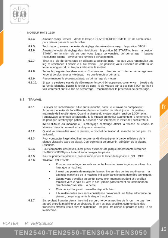
PLATEA R VERSIBLES 15
fr
TEN2540-TEN2550-TEN3040-TEN3050
- MOTEUR HATZ 1B20
6.2.4. Amenez compl tement droite le levier d OUVERTURE/FERMETURE de combustible pour laisser passer le combustible.
6.2.5. Tout d abord, amenez le levier de réglage des révolutions jusqu la position STOP. 6.2.6. Amenez le levier de réglage des révolutions la position 1/2 START ou bien la position
START, en fonction de ce que vous jugez convenable. Le démarrage basses révolutions aidera diminuer les fumées d échappement.
6.2.7. Tirez le c ble de démarrage en utilisant la poignée jusqu ce que vous remarquiez une lég re résistance. Laissez le c ble revenir sa position; vous utiliserez de cette fa on toute la longueur du c ble pour démarrer le moteur.
6.2.8. Tenez la poignée des deux mains. Commencez tirer sur le c ble de démarrage avec force et de plus en plus vite jusqu ce que le moteur démarre.
6.2.9. Recommencez le processus jusqu au démarrage du moteur. 6.2.10. Si apr s plusieurs essais de démarrage, le pot d échappement commence émettre de
la fumée blanche, placez le levier de contr le de vitesse sur la position STOP et tirez 5 fois lentement sur le c ble de démarrage. Recommencez le processus de démarrage.
6.3 TRAVAIL
6.3.1. Le levier de l accélérateur, situé sur le manche, contr le le travail du compacteur. Actionnez le levier de l accélérateur depuis la position de ralenti jusqu la position maximale de l accélérateur. Quand la vitesse du moteur atteint environ 2.300 r.p.m., l embrayage centrifuge se raccorde. Si la vitesse du moteur augmente tr s lentement, il se peut que l embrayage patine. N actionnez pas lentement le levier de l accélérateur. IMPORTANT: Au moment o l embrayage centrifuge atteint la vitesse de coupe, la vibration dans la caisse d excentriques commence.
6.3.2. Quand vous travaillez avec le plateau, le crochet de fixation du manche de doit pas tre actionné.
6.3.3. Pour compacter l asphalte, il est recommandé d imprégner la partie inférieure de la plaque vibratoire avec du diesel. Ceci permettra de prévenir l adhésion de la plaque l asphalte.
6.3.4. Pour compacter des pavés, il est prévu d utiliser une plaque amortissante référence ENARCO C0028 pour éviter d endommager les pavés.
6.3.5. Pour supprimer la vibration, passez rapidement le levier de la position ON OFF. 6.3.6. TRAVAIL EN PENTE
� Pour le compactage des sols en pente, l ouvrier devra toujours se situer plus haut que la machine.
� Il n est pas permis de manipuler la machine sur des pentes supérieures la capacité maximale de la machine indiquée dans le point données techniques.
� Quand vous travaillez en pente, soyez extr mement prudent et travaillez toujours vers le haut ou vers le bas, jamais partiellement ou totalement en direction transversale la pente.
� Commencez toujours travailler depuis le bas. � L humidité ou les sols sans consistance provoquent une faible adhérence du
plateau, ce qui augmente le risque d accident. 6.3.7. En reculant, l ouvrier devra tre situé sur un c té de la machine de fa on ne pas tre
attrapé entre la machine et un obstacle. Si ce n est pas possible, comme dans des tranchées étroites, il faut faire tr s attention ne pas tre coincé et perdre le contr le de la machine.

PLATEA R VERSIBLES
fr
16 TEN2540-TEN2550-TEN3040-TEN3050
6.3.8. Il faudra faire tr s attention pendant le compactage de terrains accidentés ou présentant des irrégularités. L ouvrier devra se situer sur un sol ferme et stable.
6.4 ARR T DU MOTEUR
- MOTEUR HONDA GX160 / ROBIN EX17
6.4.1. Avant d arr ter le moteur, laissez-le au ralenti pendant 2-3 minutes et ensuite appuyez sur le bouton d arr t sur le manche du plateau jusqu ce que le moteur s arr te compl tement.
6.4.2. Fermez le robinet de combustible.
- MOTEUR HATZ 1B20
6.4.3. Pour arr ter le moteur, amenez le levier de l accélérateur au ralenti, ensuite appuyez sur le bouton rouge d arr t et ne le l chez pas jusqu ce que le moteur s arr te. Vérifiez qu en le l chant, le bouton revient sa position d origine.
6.4.4. Fermez le robinet de combustible en mettant compl tement gauche le levier d OUVERTURE/FERMETURE de carburant.

PLATEA R VERSIBLES 17
fr
TEN2540-TEN2550-TEN3040-TEN3050
7 ENTRETIEN
7.1 CALENDRIER D ENTRETIEN
Intervalles Zone d Entretien Travail d Entretien Point
Moteur - Vérifier niveau d huile - Vérifier filtre air
7.4 7.3
Moteur Hatz - Vérifier séparateur d eau Quotidien ou toutes les 8
heures Machine
- Vérifier s il y a des dommages, fuites ou similaires - Nettoyer la partie inférieure de la plaque vibrante
Moteur - Vidange - Vérifier connexions vissées - Nettoyage du filtre air
7.4
7.3
Moteur Hatz - Vérifier et ajuster le jeu des soupapes
Premi res 20 heures
Machine - Vérifier et ajuster la courroie trapézo dale 7.10
Moteur - Vérifier connexions vissées - Nettoyer syst me de réfrigération
Hebdomadaire ou toutes les
50 heures Machine - Vérifier les amortisseurs en caoutchouc - Vérifier niveau d huile de vibrateur - Vérifier et ajuster la courroie trapézo dale
7.12
Moteur - Vidange 7.4
Moteur Hatz - Nettoyer la pi ce réticulée du pot d échappement - Vérifier et ajuster le jeu des soupapes
Moteur Honda / Robin
- Nettoyer le dép t de sédiments - Vérifier bougie
7.7 7.2
Mensuel ou toutes les 250
heures
Machine - Vérifier et ajuster serrage des vis - Commande hydraulique: voir niveau et remplir si besoin
7.13
Moteur Hatz - Changer élément du filtre de combustible 7.9 Semestriel ou toutes les 500
heures Moteur Honda / Robin
- Vérifier et ajuster graduation du carburateur - Vérifier et ajuster jeu des soupapes - Vidanger le vibrateur
7.6
7.12
Moteur Hatz - Nettoyer filtre huile 7.9
Moteur Honda / Robin
- Nettoyer chambre de combustion - Nettoyer réservoir et filtre de combustible - Vérifier le tuyau de combustible
Annuel ou toutes les 1000
heures
Machine - Enlever les saletés, graisse usée et remplacer les parties
oxydées

PLATEA R VERSIBLES
fr
18 TEN2540-TEN2550-TEN3040-TEN3050
Emmagasinage: Quand vous rangez la plaque vibrante pendant une longue période : A.- Videz compl tement le combustible du réservoir, celui du tuyau de combustible et celui du carburateur B.- Retirez la bougie et mettez quelques gouttes d huile de moteur dans le cylindre. Tournez manuellement plusieurs fois le moteur pour que l huile se répande sur la partie intérieure du cylindre. C.- Nettoyez la superficie externe de la machine avec un linge humecté d huile, recouvrez l unité et rangez la dans un lieu l abri de l humidité et de la poussi re.
7.2 CARACTÉRISTIQUES DE LA BOUGIE DU MOTEUR ET SERVICE (HONDA / ROBIN).
En plus de l entretien hebdomadaire prescrit dans le calendrier d entretien, nettoyez et remplacez la bougie autant de fois qu il est nécessaire pour le bon fonctionnement du moteur. Pour cela, consultez le manuel d explications du moteur qui est remis avec la plaque vibrante. Consultez le point 4.1 DONNÉES DU MOTEUR pour choisir la bougie et pour conna tre l entrefer. 7.2.1. Retirez le bouchon de la bougie et utilisez une clé bougie appropriée pour extraire la
bougie. 7.2.2. Vérifiez visuellement la bougie et remplacez-la si elle est usée ou si l isolateur est cassé
ou fissuré. 7.2.3. Si la bougie est bonne, nettoyez-la avec une brosse métallique 7.2.4. Vérifiez que l entrefer est entre 0,7 et 0,8 mm.
0.7 – 0.8 mm
7.2.5. Vérifiez que la rondelle de la bougie est en bonne condition et installez la bougie
manuellement pour éviter de déformer l anneau. 7.2.6. Ensuite, serrez l aide de la clé bougie pour comprimer la rondelle.
Comme vous installez une bougie neuve, serrez-la d 1/2 tour apr s son assise. Si la bougie est usagée, serrez-la entre 1/8 et 1/4 de tour apr s son assise. ATTENTION: la bougie doit tre serrée fermement, parce que sinon elle chauffera et elle pourrait endommager le moteur.

PLATEA R VERSIBLES 19
fr
TEN2540-TEN2550-TEN3040-TEN3050
!
7.3 ENTRETIEN DU FILTRE AIR
Un filtre air sale peut provoquer un mauvais fonctionnement du carburateur. Nettoyez souvent le filtre et plus fréquemment si beaucoup de poussi re se forme en travaillant. ATTENTION: N utilisez pas le moteur sans filtre air, cela provoquerait une rapide détérioration du moteur.
Ne nettoyez jamais les éléments du filtre du moteur avec des combustibles ou des dissolvants haut degré d inflammation. Cela pourrait provoquer une explosion ou un incendie.
MOTEUR HONDA / ROBIN: 7.3.1. Dévissez la vis papillon et retirez le couvercle du filtre air. Enlevez les éléments,
vérifiez-les et changez-les s ils ont des trous ou s ils sont fissurés. 7.3.2. Élement en mousse: lavez-le dans une solution savonneuse et rincez-le parfaitement
l eau claire. Vous pouvez aussi le laver avec des dissolvants qui ne sont pas inflammables. Laissez-le sécher compl tement. Trempez l élément dans de l huile de moteur propre et essorez-le pour enlever l exc s d huile.
7.3.3. Élement en papier: frappez-le lég rement plusieurs fois contre une superficie dure pour expluser l exc s de saleté, ou appliquez-y de l air comprimé de l intérieur vers l extérieur.
VIS PAPILLON
COUVERCLE DU FILTRE AIR
ÉLÉMENT EN PAPIER
ÉLÉMENT EN MOUSSE
Filtre moteur Robin EX17 Filtre moteur Honda GX 160

PLATEA R VERSIBLES
fr
20 TEN2540-TEN2550-TEN3040-TEN3050
7.3.4. Remonter la cartouche en suivant le processus inverse.
Moteur Hatz
7.3.5. Dévisser la vis du bouchon du filtre. 7.3.6. Sortir la cartouche du filtre de sa place dans le filtre air. Secouez-le ou soufflez-le
basse pression. 7.3.7. Insérer de nouveau le filtre. 7.3.8. Placer de nouveau le bouchon et le fermer en revissant.
! ATTENTION:
� Si un degré de propreté satisfaisant n est pas atteint (Ex: saleté humide ou graisseuse), il faudra alors placer une nouvelle cartouche de filre.
� Vérifier que le joint de la cartouche n est pas ab mé. � Vérifier quil n y a pas de fissures sur la cartouche du filtre ni aucun autre type
de dommage sur le filtre en papier, en le pla ant face la lumi re ou en l illuminant avec une source de lumi re artificielle.

PLATEA R VERSIBLES 21
fr
TEN2540-TEN2550-TEN3040-TEN3050
7.4 VIDANGE DU MOTEUR
7.4.1. Le moteur doit tre en position horizontale et arr té. 7.4.2. Drainez l huile quand le moteur est encore ti de pour faciliter une vidange rapide et
compl te. 7.4.3. Placez un récipient sous le moteur pour récupérer l huile.
MOTEUR HONDA:
7.4.4. Dévissez le bouchon de remplissage et le bouchon de drainage et videz dans un récipient. Revissez fortement le bouchon de drainage.
7.4.5. Ajoutez l huile recommandée jusqu au niveau (voir point 4.1 DONNÉES DU MOTEUR) 7.4.6. Vissez et serrez le bouchon de remplissage.
BOUCHON D HUILE / JAUGE
NIVEAU BOUCHON DE DRAINAGE
Moteur Honda/Robin
MOTEUR HATZ:
7.4.7. Placer un récipient sous le moteur pour récupérer l huile. 7.4.8. Enlever le bouchon de vidange d huile et attendre que toute l huile soit drainée. 7.4.9. Nettoyer le bouchon de vidange, placer une nouvelle rondelle et serrez de nouveau
(50Nm). 7.4.10. Ajouter de l huile de moteur. (voir paragraphe. données techniques)
Moteur Hatz
! ATTENTION: Défaites-vous de l huile résiduelle selon les normes en vigueur. Pour vérifier le niveau d huile, sortez la jauge de niveau, nettoyez-la, remettez-la en vissant le bouchon et finalement sortez-la de nouveau. Vérifez le niveau sur la jauge et remplissez si nécessaire jusqu au trait de maximum.
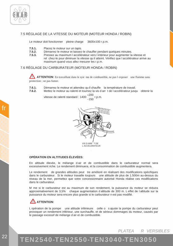
PLATEA R VERSIBLES
fr
22 TEN2540-TEN2550-TEN3040-TEN3050
7.5 RÉGLAGE DE LA VITESSE DU MOTEUR (MOTEUR HONDA / ROBIN)
Le moteur doit fonctionner pleine charge 3600±100 r.p.m. 7.5.1. Placez le moteur sur un tapis. 7.5.2. Démarrez le moteur et laissez-le chauffer pendant quelques minutes. 7.5.3. Pressez au maximum l accélérateur vers l intérieur pour augmenter la vitesse et
rel chez-le pour diminuer la vitesse qu il atteint. Vérifiez que l accélérateur arrive au maximum quand vous allez mesurer les r.p.m.
7.6 RÉGLAGE DU CARBURATEUR (MOTEUR HONDA / ROBIN)
! ATTENTION: En travaillant dans le syst me de combustible, ne pas l exposer une flamme sans protection ; ne pas fumer. 7.6.1. Démarrez le moteur et attendez qu il chauffe la température de travail. 7.6.2. Mettez le moteur au ralenti et tournez la vis d arr t de l accélérateur jusqu obtenir la
vitesse de ralenti standard : 1400150200
��
r.p.m.
VIS D ARR T DE L ACCÉLÉRATEUR
OPÉRATION EN ALTITUDES ÉLEVÉES:
En altitude élevée, le mélange d air et de combustible dans le carburateur normal sera excessivement riche. Le rendement diminuera, et la consommation de combustible augmentera.
Le rendement de grandes altitudes peut tre amélioré en réalisant des modifications spécifiques dans le carburateur. Si le moteur travaille toujours une altitude de plus de 1.500m au-dessus du niveau de la mer, permettez que votre concessionnaire autorisé Honda réalise ces modifications dans le carburateur.
M me si le carburateur est au maximum de son rendement, la puissance du moteur se réduira approximativement de 3,5% chaque augmentation d altitude de 300 m. L effet de l altitude sur la puissance du moteur sera encore plus grande si le carburateur n est pas modifié.
! ATTENTION:
L opération de la pompe une altitude inférieure celle o s ajuste la pompe du carburateur peut provoquer un rendement inférieur, une surchauffe, et de sérieux dommages du moteur, causés par le passage excessif de mélange d air et de combustible.

PLATEA R VERSIBLES 23
fr
TEN2540-TEN2550-TEN3040-TEN3050
7.7 NETTOYAGE DU DÉP T DE SÉDIMENTS (MOTEUR HONDA / ROBIN)
7.7.1. Fermez la soupape de combustible. 7.7.2. Sortez le dép t de sédiments avec le joint torique. 7.7.3. Lavez-les avec du dissolvant non-inflammable, séchez-les et réinstallez-les fermement. 7.7.4. Ouvrez la soupape de combustible, vérifiez qu il n y a pas de fuites et que la zone est
s che avant de procéder au démarrage du moteur.
JOINT TORIQUE
BOUCHON DE SÉDIMENTS

PLATEA R VERSIBLES
fr
24 TEN2540-TEN2550-TEN3040-TEN3050
7.8 CHANGEMENT DU FILTRE DE COMBUSTIBLE (MOTEUR HATZ)
Les intervalles de temps d entretien du filtre de la pompe de combustible dépendent de la pureté du combustible diesel utilisé, et si c est nécessaire, l intervalle se réduira 250 heures. ! ATTENTION:
� Quand on travaille dans le syst me de combustible, ne pas l exposer une flamme sans protection ; ne pas fumer.
! IMPORTANT: � Réaliser le travail proprement, pour éviter la pénétration de saleté dans le tuyau de
combustible. � Des particules de combustible peuvent causer des dommages dans le syst me
d injection.
7.8.1. Ouvrir le bouchon du dép t et extraire le filtre de combustible de sa place dans le dép t, l aide de la ficelle.
7.8.2. Dévisser la conduite de combustible „1“ du filtre „2“ et placer un nouveau filtre. 7.8.3. Placer de nouveau le filtre et fermer le bouchon du dép t de combustible. 7.8.4. La purge du syst me d injection de combustible se réalise automatiquement.
7.9 NETTOYAGE DU FILTRE HUILE (MOTEUR HATZ)
Le filtre huile devrait tre nettoyé en m me temps qu on change l huile, puisqu il peut y avoir des pertes d huile quand on change le filtre.
! ATTENTION: � Le moteur doit tre en position horizontale et arr t . � Danger de br lures par huile chaude! � Se d faire de l huile r siduelle selon les normes en vigueur.
7.9.1. Desserrez la vis „1“ (5 tours environ). 7.9.2. Sortez le filtre de la carcasse. 7.9.3. Utilisez de l air pression de l intérieur vers l extérieur pour éliminer la saleté du filtre. 7.9.4. Vérifiez l état du joint „1“; s il est ab mé, changez-le. 7.9.5. Vérifiez que l état du joint „2“ est bon et qu il se trouve correctement ajusté; en cas de
besoin, changez le filtre huile. 7.9.6. Lubrifiez le joint avant de le placer. 7.9.7. Insérez le filtre et pressionnez au maximum. 7.9.8. Faites attention ce que les extrémités „1“ des ressorts de tension se trouvent avec le
filtre huile avant de serrer la vis. 7.9.9. Vérifiez le niveau d huile sur la jauge et, si besoin, ajoutez de l huile jusqu au trait MAX.
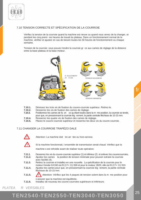
PLATEA R VERSIBLES 25
fr
TEN2540-TEN2550-TEN3040-TEN3050
7.10 TENSION CORRECTE ET SPÉCIFICATION DE LA COURROIE
Vérifiez la tension de la courroie quand la machine est neuve ou quand vous venez de la changer, et pendant les cinq premi res heures de travail du plateau. Dans un fonctionnement normal de la machine, vérifiez et ajustez en cas de besoin toutes les 50 heures de fonctionnement ou chaque semaine. Tension de la courroie: vous pouvez tendre la courroie gr ce aux cames de réglage de la distance entre la base plateau et la base moteur.
TENSADO MÁXIMO TENSADO MÁXIMO
TENSADO MÍNIMO TENSADO MÍNIMO
7.10.1. Dévissez les trois vis de fixation du couvre-courroie supérieur. Retirez-le. 7.10.2. Desserrez les vis de fixation des cames de réglage. 7.10.3. Positionnez les cames de fa on ce qu étant toutes dans la m me position, la courroie se tende,
pour que, en pressionnant la courroie lég rement, la partie centrale fléchisse de 10-15 mm. 7.10.4. Resserrez les quatre vis de fixation des cames de réglage. 7.10.5. Placez le couvre-courroie supérieur et resserrez les deux vis du couvre-courroie .
7.11 CHANGER LA COURROIE TRAPÉZO DALE
! Attention: La machine doit tre arr tée ou hors-service.
! Si la machine fonctionnait, l ensemble de transmission serait chaud. Vérifiez que la machine s est refroidie avant de réaliser toute opération.
7.11.1. Desserrez les vis du couvre-courroie supérieur (1) et inférieur (2) et enlevez les couvrecourroies. 7.11.2. Ajustez les cames la position de tension minimale pour pouvoir extraire la courroie
avec facilité (4). 7.11.3. Retirez la courroie et installez-en une nouvelle. La spécification de la courroie pour le
moteur Honda GX160 est B (17× 11) 930 et pour le moteur 1B20, elle est B (17× 11) 910. 7.11.4. Ajustez les cames pour que, en pressionnant la courroie lég rement, la partie centrale
fléchisse de 10-15 mm. 7.11.5. ! Attention: Vérifiez que les 4 paques de tension soient dans la m me position pour
s assurer que la machine est équilibrée. 7.11.6. Installez de nouveau les couvre-courroies supérieure et inférieure.
D PLACEMENT 10 15 mm TENSION MAXIMUM
TENSION MINIMUM

PLATEA R VERSIBLES
fr
26 TEN2540-TEN2550-TEN3040-TEN3050
7.12 ENTRETIEN DE L ENSEMBLE VIBRATOIRE
Vérifiez le niveau d huile toutes les 50 heures de fonctionnement de la plaque vibrante. Placez la machine sur une surface horizontale et plate. Dévissez le bouchon d huile avec sa rondelle. Si le niveau d huile est en-dessous de la vis, ajoutez de l huile et revissez le bouchon d huile.
Remplacez l huile toutes les 300 heures de travail.
! ATTENTION: La machine doit tre arr tée ou hors-service. Vider seulement l huile avec la machine chaud. Danger de br lures par huile chaude! Se défaire de l huile résiduelle selon les normes en vigueur. 7.12.1. Inclinez lég rement la machine du c té inverse au c té o l huile va tre vidée. 7.12.2. Remuez le bouchon de vidange d huile vibratoire (1). 7.12.3. Inclinez maintenant la machine de l autre c té et attendez que toute l huile soit drainée. 7.12.4. Inclinez de nouveau la machine vers le premier c té et remplissez avec 1 L. d huile Shell
MORLINA 100. 7.12.5. Replacez le bouchon.
1

PLATEA R VERSIBLES 27
fr
TEN2540-TEN2550-TEN3040-TEN3050
7.13 ENTRETIEN DE LA COMMANDE HYDRAULIQUE
Vérifiez le niveau du circuit chaque mois ou toutes les 250 heures.
7.13.1. Prenez le manche en position hors-service. 7.13.2. Remuez le bouchon de contr le de la carcasse du manche. 7.13.3. Vérifiez que l huile arrive jusqu au bord inférieur de l orifice.
! ATTENTION: La machine doit tre arr tée ou hors-service. Pour remplir le circuit
7.13.4. Remuez le bouchon supérieur de la carcasse de la pompe du manche (2). 7.13.5. Mettez le manche dans sa position la plus avancée. 7.13.6. Remplissez d huile Shell MORLINA 100 l orifice de la pompe et pompez avec le manche
pour que l huile descende. Refaites l opération jusqu ce que tout le circuit se soit rempli d huile.
7.13.7. Fermez l orifice de contr le.
7.13.8. Fermez l orifice de remplissage.
2

PLATEA R VERSIBLES
fr
28 TEN2540-TEN2550-TEN3040-TEN3050
7.14 LOCALISATION ET RÉPARATION DE PANNES
MOTEUR ESSENCE
Ne d marre pas: - Il y a du combustible et la bougie ne fait pas d tincelles
� Il y a de l électricité dans le c ble de haute tension � Il y a de l électricité dans le c ble de haute tension � Bougie d allumage placée en pont � Dép t de charbon dans la bougie d allumage � Court circuit d un isolement déficient de la bougie d allumage � Séparartion incorrecte entre électrodes
� Il n y a pas d électricité dans le c ble de haute tension � Interrupteur du bouton d arr t en court circuit � Bobine d allumage défectueuse � Isolement du condensateur déficient ou en court circuit � Bobine d allumage cassée ou en court circuit
� Compression satisfaisante � Combustible incorrect � De l eau ou de la poussi re est entrée � Filtre air déficient
- Il y a du combustible et la bougie d allumage fait des tincelles � Compression déficiente
� Soupape d admission ou d échappement collée ou défectueuse � Anneau du piston ou cylindre usé � Culasse du cylindre ou bougie d allumage mal ajustée � Joint de culasse ou joint de la bougie d allumage défectueuse
� L embrayage bloqué fait que le vibrateur tourne quand on essaie de démarrer � Il n y a pas de combustible dans le carburateur
� Réservoir de combustible vide � Le robinet de combustible n est pas correctement ouvert � Filtre de combustible obturé � Orifice de ventilation d air du couvercle du réservoir obturé � Air retenu dans le tube � Soupape d entrée du carburateur collée
Puissance Nulle:
- Puissance insuffisante � Compression normale et on n observe pas d erreur de l allumage
� Filtre air déficient � Dép t de charbon dans le cylindre � Niveau de combustible dans le carburateur incorrect
� Compression insuffisante � (Voir “Compression déficiente” plus haut)
� La compression est correcte mais l allumage est défectueux � Il y a de l eau dans le combustible � La bougie d allumage est sale
PLATEA R VERSIBLES 29
fr
TEN2540-TEN2550-TEN3040-TEN3050
� Bobine d allumage défectueuse � La bobine d allumage court circuite souvent
� Vibrateur plein avec exc s d huile - Moteur surchauff
� Dép t de charbon dans la chambre de combustion ou dans la pipe d échappement
� Pouvoir calorifique de la bougie d allumage incorrect � Ailettes de refroidissement sales
- La vitesse de rotation varie � Réglage du régulateur incorrect � Ressort du régulateur incorrect � Flux de combustible déficient � De l air entre dans le collecteur d admission
Fonction du d marreur de reflux d ficient - Partie rotative coll e avec de la poussi re - Faille du ressort h lico dal
MOTEUR DIESEL (refroidi par de l air)
D marrage d fectueux: A.- Compression insu isante
� Compression nulle � Soupape de succion ou d échappement défectueuse � Réglage du syst me de décompression incorrect
� Il y a tr s peu de compression ou elle est tr s faible � Contact de l installation du si ge de soupape déficient � Bague du piston usée � Cylindre usé � Superficie de réglage du cylindre et de la culasse du cylindre défectueuse � Si ge d injecteur mal serré
B.- Il n’y a pas d’injection correcte de combustible dans la chambre de combustion.
� Flux de combustible insuffisant ou nul � Orifice de ventilation d air obturé sur le couvercle du réservoir � Passage du filtre de combustible et tamis du filtre obturés � Robinet du filtre de combustible fermé � Air retenu dans le tuyau (spécialement quand le réservoir est vide)
� Il n y a pas d injection de combustible dans la chambre de combustion � Cylindre de la pompe d injection ou piston collé � Injecteur obturé � Aiguille de l injecteur collée � Réservoir de combustible vide � Entrée d eau ou de poussi re
C.- yst me de combustible et de compression, etc., normau , mais pas de d marra e

PLATEA R VERSIBLES
fr
30 TEN2540-TEN2550-TEN3040-TEN3050
� La vitesse de démarrage n est pas atteinte � Processus de démarrage incorrect � Viscosité élevée ou contamination excessive de l huile du moteur � Air retenu dans le tuyau
Puissance de sortie insuffisante. Compression insuffisante:
� Moteur surchauffé et soupape sale � Ailettes de refroidissement sales � Eau dans le filtre de combustible � Dép t de charbon dans la chambre de combustion ou dans la pipe
d échappement � Réglage de fumée incorrect � Surcharge � Réglage de l avance l injection incorrect � Injecteur obturé
� La vitesse fluctue � Contact incorrect entre la grille du régulateur et la douille � Ressort du régulateur incorrect � Plaque du balancier et d autres parties glissantes usées ou fonctionnement
défectueux
� La vitesse du moteur n augmente pas correctement � Synchronisation incorrecte de la soupape � Pipe d échappement ou silencieux obturé � Surcharge
� Allumage défectueux accompagné de fumée blanche � Piston, Cylindre, Anneau usés � Injecteur obturé � Bague du piston supérieur et inférieur montés l envers � Réglage de l avance l injection incorrect � Synchronisation incorrecte de la soupape � Joint de la pompe injection desserré
� Consommation élevée de combustible (On observe une fuite sombre) � Fuite dans la conduite de combustible � lément de filtre air obturé � Combustible défectueux car contenant des impuretés � Surcharge
� Partie glissante trop usée ou segment du piston collé � On utilise de l huile défectueuse � On néglige le changement d huile � lément du filtre air défectueux ou sale
� Arr t brusque accompagné d un bruit anormal � Engrenage ou piston endommagé
� Huile lubrifiante diluée, augmentant son volume � Corps du piston de la pompe d injection usé
� Le moteur ne s arr te pas, m me en interrompant l approvisionnement de combustible (ou provoque un surrégime)
� Trop d huile � Installation incorrecte du syst me de régulation � Ch ssis de la pompe d injection déplacé

PLATEA R VERSIBLES 31
fr
TEN2540-TEN2550-TEN3040-TEN3050
MANIPULATION DE LA MACHINE
Elle se d place obliquement
� Puissance du moteur insuffisante � L embrayage patine � La courroie en V patine � Huile du vibrateur excessive � Parties internes du vibrateur défectueuses
Elle n avance pas � Courroie en V découplée ou qui patine � L embrayage patine � Faille mécanique dans la bo te d excentriques: contactez avec le
Service Technique d Enarco. � Si elle vibre mais ne se déplace pas, le vibrateur peut se trouver sur
une superficie humide et glissante. Essayez sur une superficie adéquate.
Recul basse vitesse
� Il manque de l huile dans la commande hydraulique du plateau: remplissez d huile en suivant le point .13.
� Air dans le circuit de la commande hydraulique: purgez le circuit.
Progression basse vitesse � Exc s d huile dans la commande hydraulique: retirez de l huile du
circuit jusqu arriver au niveau du contr le. Fuites d huile hydraulique
� Perte d étanchéité, tuyau hydraulique défectueux: remplacez les composants défectueux.

PLATEA R VERSIBLES
fr
32 TEN2540-TEN2550-TEN3040-TEN3050
8 EN CAS DE PANNE
8.1 INSTRUCTIONS POUR COMMANDER DES PI CES DE RECHANGE
1. Dans toutes les commandes de pi ces de rechange, ON DOIT INCLURE LA RÉFÉRENCE DE LA PI CE SELON LA LISTE DE PI CES. Il est recommandé d inclure le NUMÉRO DE FABRICATION DE LA MACHINE.
2. La plaque d identification avec les numéros de série et le mod le se trouvent sur la partie supérieure de la base moteur.
3. Fournissez-nous les instructions de transport correctes, en précisant la route préférée, l adresse et le nom complet du consignataire.
4. Ne retournez pas de pi ces de rechange l usine moins d en avoir l autorisation écrite, tous les retours autorisés devront tre envoyés en port payé.
8.2 INSTRUCTIONS POUR FAIRE VALOIR LA GARANTIE
1. La garantie a une validité d 1 an partir de l achat de la machine. La garantie couvrira les pi ces présentant un défaut de fabrication.
2. En aucun cas la garantie ne couvrira une panne pour un mauvais usage de la machine. 3. Dans toutes les demandes de garantie, IL FAUT ENVOYER LA MACHINE ENARCO, S.A.
OU ATELIER AGRÉÉ, en indiquant toujours l adresse et le nom complet du consignataire. 4. Le département de Service Technique notifiera immédiatement si la garantie est acceptée, et
en cas de demande, un rapport technique sera envoyé. 5. Il n y aura aucun type de garantie sur toute machine qui aurait été manipulée au préalable par
des personnes non rattachées ENARCO, S.A.

PLATEA R VERSIBLES 33
fr
TEN2540-TEN2550-TEN3040-TEN3050
9 ADRESSES UTILES
ENARCO, S.A.
o Adresse: C/ Burtina, 16 50197 ZARAGOZA, ESPAGNE
o Téléphone: (34) 976 464 090 o Fax: (34) 976 471 470
PAGE WEB: http://www.enar.es SERVICE ATTENTION TECHNIQUE: [email protected]
NOTE: ENARCO, S.A. se réserve le droit de modifier toute donnée de ce manuel sans avis préalable.

REVERSIERBARE PLATTEN 1
de
TEN2540-TEN2550-TEN3040-TEN3050
IN T E EIC NI
1 VORWORT 3
2 SICHERHEITSHINWEISE 4 2.1 SICHERHEIT BEIM MASCHINENBETRIEB ................................................ 4 2.2 SICHERHEIT BEIM MOTORBETRIEB.......................................................... 5 2.3 SICHERHEIT BEIM SERVICE........................................................................ 5 2.4 PI TOGRAMME.............................................................................................. 6
3 RECYCLING 7
4 TECHNISCHE ANGABEN 8 4.1 MOTORANGABEN ......................................................................................... 8 4.2 ANGABEN ZUR MASCHINE ......................................................................... 8 4.3 MAXIMALE NEIGUNG DER PLATTE IM BETRIEB ................................... 9 4.4 A USTI - UND VIBRATIONSMESSUNGEN.............................................. 9
5 BEDIENUNGSANWEISUNGEN 10 5.1 BESCHREIBUNG DER FUN TIONS EISE............................................... 10 5.2 AN ENDUNGEN.......................................................................................... 10 5.3 MASCHINENTRANSPORT .......................................................................... 12
6 BETRIEBSWEISE 14 6.1 VOR AUFNAHME DER T TIG EIT........................................................... 14 6.2 INBETRIEBNAHME...................................................................................... 14 6.3 ARBEIT........................................................................................................... 15 6.4 MOTORSTOPP............................................................................................... 16
7 WARTUNG 17 7.1 ARTUNGS ALENDER ............................................................................. 17 7.2 EIGENSCHAFTEN DER MOTORZ ND ERZE UND SERVICE
(HONDA / ROBIN) ......................................................................................... 18 7.3 LUFTFILTER ARTUNG ............................................................................. 19 7.4 MOTOR L ECHSEL................................................................................... 21 7.5 MOTORGESCH INDIG EITSEINSTELLUNG (HONDA / ROBIN
MOTOR).......................................................................................................... 22 7.6 VERGASEREINSTELLUNG (HONDA / ROBIN MOTOR) ......................... 22 7.7 ABSETZBEH LTERREINIGUNG (HONDA / ROBIN MOTOR) ............... 23

REVERSIERBARE PLATTEN
de
2 ���������������������������
7.8 KRAFTSTOFFFILTER WECHSELN (HATZ MOTOR) ............................... 247.9 ÖLFILTER REINIGEN (HATZ MOTOR)...................................................... 247.10 RICHTIGE RIEMENSPANNUNG UND -SPEZIFIZIERUNG.................... 257.11 KEILRIEMEN AUSWECHSELN................................................................. 257.12 WARTUNG DER VIBRATIONSBAUGRUPPE.......................................... 267.13 WARTUNG DER HYDRAULIKSTEUERUNG .......................................... 277.14 STÖRUNGSFINDUNG UND ABHILFE ..................................................... 28
8 IM STÖRUNGSFALL 32
8.1 ANWEISUNGEN ZUR ERSATZTEILBESTELLUNG ................................. 328.2 ANWEISUNGEN ZUR BEANTRAGUNG DER
GEWÄHRLEISTUNG .................................................................................... 32
9 WICHTIGE ANSCHRIFTEN 33

REVERSIERBARE PLATTEN 3
de
���������������������������
1 VORWORTWir bedanken uns für das Vertrauen, das Sie in die Marke ENAR gesetzt haben.
Um die Eigenschaften und Arbeitsweisen der Rüttelplatte kennen zu lernen, ist es wichtig, dieses Handbuch zu lesen. Bevor Sie die Arbeit mit der Maschine beginnen oder Wartungstätigkeiten daran ausführen, müssen Sie die in diesem Handbuch enthaltenen Sicherheitsanweisungen gelesen und verstanden haben, und sie befolgen.
Sollten Sie das Handbuch verloren haben oder eine weitere Ausgabe benötigen, fordern Sie es bitte bei ENARCO an oder greifen sie auf das Handbuch im elektronischen Format auf der ENARCO – Homepage http://www.enar.es zu und drucken Sie es aus.
Eine ordnungsgemäße Wartung gewährleistet lange Lebensdauer und ausgezeichnete Leistung des Geräts.
In diesem Handbuch geben wir zwar einige Anweisungen zum Motor gegeben, aber bezüglich Wartung und Reparaturen des Motors empfehlen wir das Bedienungshandbuch des Motors.
Sollten Sie Auskunft über Betrieb oder Wartung dieser Maschine benötigen, wenden Sie sich bitte telefonisch, per Fax, oder mit einer Anfrage per E-Mail an den ENARCO Kundendienst unter [email protected] oder über die Homepage in der Rubrik Servicio ENAR.

REVERSIERBARE PLATTEN
de
4 ���������������������������
2 SICHERHEITSHINWEISE 2.1 SICHERHEIT BEIM MASCHINENBETRIEB
Durch fehlerhafte Anwendung oder Wartung des Geräts können Gefahrensituationen entstehen. Lesen Sie und begreifen Sie die Anweisungen in diesem Abschnitt, bevor sie die Arbeit mit der Maschine beginnen. Der Bediener des Geräts ist dafür verantwortlich, das Gerät mit Sicherheit bedienen zu können. Im Fall von Fragen, bitten Sie das Personal, das die
Maschine kennt, um Hinweise, oder wenden Sie sich an ENARCO.
• Der Motor wird während des Betriebs sehr heiß. Lassen Sie ihn bitte abkühlen, bevor Sie ihn berühren.
• Lassen Sie die Maschine niemals unbeaufsichtigt in Betrieb.
• Das Gerät darf nicht ohne angemessenen Riemenschutz verwendet werden. Stellen Sie immer sicher, dass er vorhanden ist und sich in gutem Zustand befindet.
• Der Bediener muss Schutzkleidung und Gehörschutz tragen.
• Verhindern Sie den Zugang Ungefugter zum Arbeitsbereich.
• Bevor Sie den Motor starten, stellen Sie bitte sicher, dass Sie bei eventuellen Fehlern wissen, wie die Maschinen ausgeschaltet wird.
• Stoppen Sie die Maschine vor ihrem Transport.
• Versuchen Sie nicht, das Gerät ohne Hilfe hochzuheben. Bitten Sie um Hilfe oder benutzen Sie ein Hubgerät, indem Sie den im Plattenkäfig eingebauten Griff zum Anheben dafür verwenden.
• Verwenden Sie das Gerät nicht, wenn es sich nicht in gutem Zustand befindet.
• Lagern Sie das Gerät an einem sauberen und trockenen Ort, wenn es nicht gebraucht wird. Die Kraft- und Hilfsstoffe müssen in gekennzeichneten Behältern entsprechend der Herstellerangaben aufbewahrt werden. Beachten Sie bitte auch die gültigen gesetzlichen Vorschriften am Lagerort.
• Änderungen und Anpassungen: Aus Sicherheitsgründen ist ohne vorherige Genehmigung ENARCOS die Ausführung jeglicher Änderungen oder Anpassungen am Gerät, wie auch die Veränderung der im Werk eingestellten Motordrehzahl, verboten. ENARCO ist von allen Haftungen, die aus Nichtbeachtung dieser Anweisung entstehen, befreit.
!

REVERSIERBARE PLATTEN 5
de
���������������������������
2.2 SICHERHEIT BEIM MOTORBETRIEB
Auf Grund ihrer hohen Entzündlichkeit sind die Kraftstoffe besonders gefährlich. Ihre fehlerhafte Verwendung kann zu schweren Personen- und Sachschäden führen. Folgende Sicherheitsregeln sind immer einzuhalten:
• Betreiben Sie das Gerät nicht innerhalb eines Gebäudes oder in geschlossenen Räumen, wenn keine angemessene Belüftung vorhanden ist. Andernfalls könnte eine Kohlenmonoxydvergiftung mit Bewusstseinsverlust und eventuellen tödlichen Folgen eintreten.
• Bevor der Kraftstofftank gefüllt wird, muss der Motor gestoppt und ein paar Minuten lang abkühlen gelassen werden.
• Während des Maschinenbetriebs und Auftankens ist Rauchen verboten.
• Füllen Sie den Tank nicht in der Nähe von offenem Feuer und tanken Sie einem gut belüfteten Bereich.
• Tauschen Sie den Kraftstofftank sofort aus, wenn er undicht ist. Er könnte andernfalls eine Explosion verursachen.
• Wird beim Tanken Kraftstoff verschüttet, muss er mit Sand aufgesaugt werden. Ziehen Sie sich um, wenn Kraftstoff auf ihre Kleidung gelangt ist.
• Stellen Sie sicher, dass der Kraftstofftank nach dem Tanken wieder gut verschlossen ist.
• Prüfen Sie nach, ob Leitungen und Kraftstofftank weder Risse noch Lecks aufweisen.
2.3 SICHERHEIT BEIM SERVICE
• Reinigen oder prüfen Sie das Gerät nicht, während es in Betrieb ist.
• Starten Sie den Motor nicht, wenn der Zylinder überschwemmt ist und bei den Benzinmotoren die Zündkerze ausgebaut wurde.
• Prüfen Sie nicht, ob die Zündkerze Funken abgibt, wenn der Zylinder mit Benzin überschwemmt ist oder Benzindämpfe vorhanden sind.
• Verwenden Sie keine Lösemittel oder Kraftstoffe zur Gerätereinigung, insbesondere nicht in geschlossenen Räumen.
• Halten Sie den Bereich in der Nähe des Schalldämpfers frei von brennbaren Stoffen.
• Bevor in Geräten mit Benzinmotor Servicetätigkeiten ausgeführt werden, muss die Zündkerze ausgebaut werden, um einen unvorhergesehenen Motorstart zu vermeiden.
• Die Verwendung des Geräts in explosionsgefährdeten Umgebungen ist verboten. Der Kraftstofftank muss dicht abschließen. Bei langen Transporten ist es sehr empfehlenswert, den Kraftstofftank des Motors zu entleeren.
• Das Transportzubehör wurde nicht konstruiert, um darauf die Platte abzustellen, sondern soll nur zum Verfahren des Geräts verwendet werden.
!

REVERSIERBARE PLATTEN
de
6 ���������������������������
2.4 PIKTOGRAMME
PIKTOGRAMM BEDEUTUNG
LWA
Lautstärke in dB (A)
2004A50012442
MOD:
NR:
Typenschild
Gehörschutz verwenden

REVERSIERBARE PLATTEN 7
de
���������������������������
3 RECYCLING
Um die Umwelt zu schützen, ist die Maschinen in einer geeigneten Recyclingwerkstatt zu entsorgen.
BAUTEIL WERKSTOFF Lenker Stahl Käfig Stahl Motorunterteil Stahl Plattenunterteil Stahl Lenkerhülle Gummi Griffhalter Aluminium Motor Aluminium Dämpfer Stahl und Gummi Riemen Gummi Gehäuse Aluminium Exzenterbaugruppe Stahl Räderhalterung Stahl Räder Kunststoff und GummiAchsen Stahl

REVERSIERBARE PLATTEN
de
8 ���������������������������
4 TECHNISCHE ANGABEN
4.1 MOTORANGABEN
HATZ 1B20 ROBIN EX 17 HONDA GX160
KRAFTSTOFF Diesel Bleifreies Benzin (3,6 l)
Bleifreies Benzin (3,6 l)
MOTORÖL SAE 10W/40 (0,9 l) SAE 10W/40 (0,6 l) SAE 10W/40 (0,6 l)
NENNLEISTUNG 3,4 kW (4,6 PS) bei 3000 U/min
4,2 kW (5,7 PS) bei 3600 U/min
4 kW (5,4 PS) bei 3600 U/min
ZÜNDKERZE ------ NGK BPR6ES DENSO W20EPR-U
LUFTSPALT ------ 0,7 mm - 0,8 mmUMDREHUNGEN 3000 ± 100 3600 ± 100
LEERLAUF 1100150200
−+ U/min 1400
150200
−+ U/min
LUFTFILTER DOPPELELEMENT DOPPELELEMENT
4.2 ANGABEN ZUR MASCHINE
EIGENSCHAFTEN MODELL MENGEN-EINHEIT TEN2540GH TEN2550GH TEN2540DH TEN2550DH TEN2540GR TEN2550GR
FLIEHKRAFT kN 25ARBEITSBREITE mm 400 500 400 500 400 500
FREQUENZ Hz (U/min) 90 (5400) 90 (5400) 85 (5300) 85 (5300) 90 (5400) 90 (5400) VERSCHIEBUNG m/min 0-22 0-22 0-20 0-20 0-22 0-22
GEWICHT kg 134 140 148 155 134 140MOTOR HONDA GX160 HATZ 1B20 ROBIN EX17
VIBRATORÖL cm3 1000 (SAE 100)
EIGENSCHAFTEN MODELL MENGEN-EINHEIT TEN3040GH TEN3050GH TEN3040DH TEN3050DH TEN3040GR TEN3050GR
FLIEHKRAFT kN 30ARBEITSBREIT
E mm 400 500 400 500 400 500
FREQUENZ Hz (U/min) 90 (5400) 90 (5400) 85 (5300) 85 (5300) 90 (5400) 90 (5400) VERSCHIEBUN
G m/min 0-22 0-22 0-20 0-20 0-22 0-22
GEWICHT kg 134 140 148 155 134 140MOTOR HONDA GX160 HATZ 1B20 ROBIN EX17
VIBRATORÖL cm3 1000 (SAE 100)

REVERSIERBARE PLATTEN 9
de
���������������������������
658
348
686
1171
935
500
400
1094
4.3 MAXIMALE NEIGUNG DER PLATTE IM BETRIEB
20°
20°
4.4 AKUSTIK- UND VIBRATIONSMESSUNGEN
- Lautstärke nach ISO 3744: LWA � 102 dB(A)
- Schalldruckpegel nach ISO 6081: LpA � 93 dB(A)
- Tatsächlicher axialer und gemittelter Beschleunigungswert nach ISO 8662 Parte 1: 5 - 10 m/s2

REVERSIERBARE PLATTEN
de
10 ���������������������������
5 BEDIENUNGSANWEISUNGEN
5.1 BESCHREIBUNG DER FUNKTIONSWEISE
Die Maschinenvibration wird anhand von drehenden Exzentern im Vibrationsteil, das an der Plattenunterseite verankert ist, erzeugt. Die Exzenter sind auf zwei gegendrehenden Achsen angeordnet. Durch Veränderung der Abweichung zwischen den gegendrehenden Exzentern wird die im Erreger erzeugte Kraftzusammenstellung, und somit auch die Schwingungsrichtung, verändert. Damit erreicht man, dass die Maschine nach vorne fährt, stehen bleibt oder rückwärts fährt. Diese Einstellung erfolgt kontinuierlich und schrittweise anhand der Hydrauliksteuerung am Kopfteil der Lenkstange.
Die Vibrationsbaugruppe wird von dem Wärmemotor der Maschine, der am Motorunterteil anhand von Bolzen befestigt ist, angetrieben. Der vom Motor erzeugte Drehmoment wird auf die Vibrationsbaugruppe anhand der am Motorausgang befindlichen Fliehkraftkupplung und dem V-Riemen, der beide Achsen verbindet, übertragen. Bei niedrigen Umdrehungen setzt die Fliehkraftkupplung nicht ein, so dass der Motor ohne Last starten und sanft auf den Leerlauf überwechseln kann. Mit dem Beschleunigungshebel kann man die Drehzahl des Motors einstellen. Er soll jedoch auf Höchstleistung betrieben werden, damit die Kupplung nicht rutscht.
Das Plattenunterteil ist mit vier Dämpfern zur Senkung der Vibrationen in den oberen Maschinenmassen mit dem Motorunterteil verbunden. Auf diese Art arbeiten Motor und Bediener sicherer.
Wenn der Griff ganz nach vorne geschoben ist, fährt die Platte mit maximaler Geschwindigkeit nach vorne. Bei Zurückziehen des Griffs reduziert sich die Vorwärtsgeschwindigkeit des Geräts, bis es sich nicht mehr vorwärts bewegt. Wird der Griff weiter zurückgezogen, fängt die Platte an, rückwärts zu fahren. Wenn der Griff am Anschlag aufschlägt, fährt die Maschine mit maximaler Geschwindigkeit rückwärts.
5.2 ANWENDUNGEN
Diese Platte ist zur Verdichtung von körnigen Böden, Kies und Pflastersteinen geeignet. Platten mit Berieselung können zur Asphaltverdichtung eingesetzt werden.
Typische Anwendungen sind die Bodenverdichtung mit körnigem Füllmaterial in Wasser- und Telefonnetzen, mittelbreiten Gruben, um Leitungsrohre, Fundamente, sowie um Wege, Bürgersteige und Fahrradwege herum.
Zu den Anwendungen bei der Asphaltverdichtung gehören Ausbesserungen und Schlaglochreparaturen auf Landstraßen.

REVERSIERBARE PLATTEN 11
de
���������������������������
MODELO
APLICACIÓNReversierbare
Platten Nicht reversierbare
Platten Stampfer
Ausbesserungsbereiche �����
��
Gebäudefundamente �� �� ��Wege und Spazierwege �� �� ��Tennis- und Sportplätze �� �� ��
Unterschichtvorbereitung ���
�� ��
Endbefestigung von Brücken und Rampen �� �� ��
Eisenbahnkreuzungen �� �� ��Aufeinanderfolgende Zementblöcke �� �� ��Netzbau �� �� ��Dränagebau �� �� ��Grubenverdichtung �� �� ��Reparaturen von Vertiefungen aufgrund von Leitungs- oder Kabelbrüchen, etc.
�� �� ��
Rund um Leitungen, Kabel, Dränagen, usw., �� �� ��
Steinauffüllungen �� �� ��Kies �� �� ��Sand oder vulkanisches Material �� �� ��Mischböden �� �� ��Schlamm �� �� ��Ton �� �� ��Schichtdicken von 0 – 25 cm �� �� ��Schichtdicken von 20 – 40 cm �� �� ��Warme Mischungen �� �� ��Kalte Mischungen �� �� ��Unterschicht - Bindeschicht 40 – 100 mm �� �� ��
Fahrspurschicht 25 – 60 mm �� �� ��
� Empfohlen � Kann eingesetzt werden � Abgeraten

REVERSIERBARE PLATTEN
de
12 ���������������������������
5.3 MASCHINENTRANSPORT
• Vor dem Plattentransport ist wie im Punkt fdffdfd beschrieben vorzugehen.
• Verriegeln Sie den Mast mit seiner Verankerung. Verwenden Sie niemals den Mast zum Anheben der Maschine.
• Um die Platte auf kurzen Entfernungen zu verfahren oder auf einen Transporter zu heben, muss sie von zwei Personen an den Transportgriffen festgehalten werden.
• Zur mechanischen Anhebung:
o Prüfen Sie, ob die Hubgeräte über ausreichende Tragfähigkeit zum Anheben der Maschine verfügen (siehe Punkt 4.2 MASCHINENANGABEN).
o Legen Sie den Hubhaken oder die Schlinge am Verankerungspunkt am Maschinenkäfig, wie auf der folgenden Abbildung dargestellt, an.
o Stellen Sie sich niemals unter schwebende Lasten.
• Die Laderampen müssen solide und stabil sein. Dabei ist darauf zu achten, dass keine Personen durch eventuelles Umstürzen oder Abrutschen des Geräts, oder auch durch Teile davon, die nach oben oder unten ausschlagen können, gefährdet werden.
• Für den Transport der Maschine in einem Fahrzeug:
o Motor abkühlen lassen
o Kraftstoffhahn schließen und den Motor aufrecht halten, um ein Verschütten des Kraftstoffs zu vermeiden.
o Binden Sie die Platte am Fahrzeug fest, um Verschieben oder Kippen zu vermeiden.

REVERSIERBARE PLATTEN 13
de
���������������������������
• Zum Verfahren der Maschinen auf dem Boden:
o Führungsmast mit Verankerung befestigen. Zubehör Radbaugruppe BW2549 auf der Vorderseite der Maschine mit in Richtung Verankerungsstellen geöffneten Befestigungsklemmen anbringen.
o Die beiden Befestigungsklemmen so anbringen, dass die Radbaugruppe fest an der Maschine verankert ist.
o Maschinengriff nach vorne neigen, indem man mit dem Fuß auf der Zentralstange der Radbaugruppe (A) nachhilft und die Platte (B) verfährt.
(A) (B) (C)
Maschine vorsichtig loslassen, indem der Fuß auf den Bügel gestützt wird, damit man nicht von der Maschine angehoben und die Platte nicht beschädigt wird (C). !

REVERSIERBARE PLATTEN
de
14 ���������������������������
6 BETRIEBSWEISE
6.1 VOR AUFNAHME DER TÄTIGKEIT
6.1.1. Reinigen Sie das Gerät vor Aufnahme der Tätigkeit von Schmutz, Matsch, usw.Dabei ist besonders auf die Innenseite der Vibrationsplatte und die Bereiche um den Kühllufteingang des Motors, Vergasers und Luftfilters zu achten. 6.1.2. Alle Schrauben prüfen und sicherstellen, dass sie fest angezogen sind. Lose Schrauben
können die Maschine beschädigen. 6.1.3. V-Riemenspannung prüfen. Die normale Schwingung muss 10 – 15 mm betragen,
(1/2”), wenn die Riemen mit Kraft auf halbem Abstand zwischen beiden Rollen eingedrückt werden. Wenn die Riemen zu viel Spiel haben, können der Aufschlag unzureichend sein, oder die Vibration unkontrolliert erfolgen und somit Schäden an der Maschine hervorgerufen werden.
6.1.4. Luftfilterzustand. 6.1.5. Ölstand des Motors prüfen und bei Bedarf nachfüllen. Der Motor hat 0,6 l
Fassungsvermögen für das Öl. SAE10W/40 Motoröl verwenden. 6.1.6. Stellen Sie sicher, dass die Platte während der Prüfung eben steht. Der Ölstand im
Vibrator muss bis zur Deckelhöhe reichen. Das Öl soll monatlich oder alle 200 Betriebsstunden gewechselt werden. Der Vibrator hat 120 cm3 Fassungsvermögen.
WICHTIG: VERWENDEN SIE SAE 10W/40 ÖL Führen Sie den Ölwechsel bei betriebswarmem Öl durch. Um das Auslaufen des Altöls zu erleichtern, neigen Sie die Maschine und klopfen leicht auf den Vibrator. 6.1.7. Im Motor ist bleifreies Normalbenzin zu verwenden. Wenn der Benzintank gefüllt wird,
müssen Sie sicher stellen, dass der Filter verwendet wird.
6.2 INBETRIEBNAHME
- HONDA GX160 / ROBIN EX17 MOTOR
6.2.1. Öffnen Sie den Kraftstoffhahn, indem Sie den Hebel auf halbgeöffnete Stellung stellen. Um einen kalten Motor zu starten, muss der Hebel der Lufteinstellung bis zur Stellung „Geschlossen“ geschoben werden. Bei warmem Motor muss der Luftregler halb oder ganz geöffnet sein. Wenn der Motorstart schwierig ist, müssen Sie sicher stellen, dass der Hebel der Luftregelung halb geöffnet ist, um zu vermeiden, dass der Vergaser durch eine Übermenge Kraftstoff überschwemmt wird.
6.2.2. Beim Ziehen am Starterseil soll man nicht die ganze Länge herausziehen, da dadurch die Rückholfeder beschädigt werden kann. Lassen Sie das Starterseil nicht plötzlich los, wenn der Motor angesprungen ist. Halten Sie den Griff in der Hand und geben sie langsam nach, damit das Seil ganz aufgewickelt wird.
6.2.3. Nach dem Motorstart müssen Sie den Hebel des Luftreglers nach und nach wieder ganz öffnen. Lassen Sie den Motor auf Mindestgeschwindigkeit 3-5 Minuten lang warm laufen. Diese Vorgehensweise, den Motor bei Mindestumdrehungen warmlaufen zu lassen, ist besonders in der kalten Jahreszeit wichtig. Während der Motor warmläuft, sollten Sie die Maschine einer allgemeinen Sichtkontrolle unterziehen, um irgendwelche Mängel feststellen zu können.

REVERSIERBARE PLATTEN 15
de
���������������������������
- HATZ 1B20 MOTOR
6.2.4. Stellen Sie den Hebel zum Kraftstoffhahn ÖFFNEN / SCHLIESSEN ganz nach rechts, um den Kraftstofffluss zu ermöglichen.
6.2.5. Stellen Sie zuerst den Einstellhebel der Umdrehungen auf die STOPP-Stellung. 6.2.6. Stellen den Einstellhebel der Umdrehungen je nach Wunsch auf 1/2 START oder auf
START-Stellung. Beim Start mit niedrigen Umdrehungen werden weniger Abgase erzeugt.
6.2.7. Ziehen Sie am Starterseil anhand des Griffs, bis Sie einen leichten Widerstand spüren. Lassen Sie das Seil wieder auf seine Stellung zurückgehen. Auf diese Art können Sie die Gesamtheit der Seillänge für den Motorstart nutzen.
6.2.8. Halten Sie den Griff mit beiden Händen fest. Ziehen sie mit Kraft am Starterseil, und zwar jedes Mal schneller, bis der Motor startet.
6.2.9. Wiederholen Sie diese Vorgehensweise, bis der Motor anspringt. 6.2.10. Wenn nach mehreren Startversuchen weißer Rauch aus dem Auspuff kommt, müssen
Sie den Geschwindigkeitskontrollhebel auf STOPP stellen und 5 x langsam am Starterseil ziehen. Wiederholen Sie den Startvorgang.
6.3 ARBEIT
6.3.1. Der Gashebel über dem Griff steuert die Arbeit des Verdichters. Bewegen Sie den Gashebel von der Leerlaufstellung bis zum Anschlag. Wenn die Motorgeschwindigkeit ca. 2.300 U/min erreicht hat, wird die Fliehkraftkupplung zugeschaltet. Steigt die Motorgeschwindigkeit sehr langsam an, rutscht möglicherweise die Kupplung. Bewegen Sie den Gashebel nicht langsam. WICHTIG: Sobald die Fliehkraftkupplung die Schnittgeschwindigkeit erreicht hat, beginnt die Vibration im Exzenterkasten.
6.3.2. Wenn die Platte arbeitet, darf die Klinke der Griffbefestigung nicht ausgelöst sein. 6.3.3. Zum Asphaltverdichten wird empfohlen, die Unterseite der Vibrationsplatte mit
Dieselkraftstoff zu imprägnieren. Dadurch wird verhindert, dass die Platte auf dem Asphalt haften bleibt.
6.3.4. Zur Pflasterverdichtung ist die Verwendung der Dämpferplatte mit der Sachnummer ENARCO C0028 vorgesehen, um Schäden am Pflaster zu vermeiden.
6.3.5. Um die Vibration zu unterdrücken, müssen Sie den Hebel schnell von ON auf OFF schieben.
6.3.6. ARBEIT IN HÄNGEN � Zur Bodenverdichtung an Hängen muss sich der Bediener immer auf eine
höhere Stellung als die Maschine stellen. � Arbeiten an größeren Hängen als die in den technischen Angaben dargestellte
maximale Maschinenkapazität sind nicht zulässig. � Bei Arbeiten an Hängen müssen Sie ausgesprochen vorsichtig sein und
immer nach oben oder nach unten arbeiten. Arbeiten Sie niemals teilweise oder ganz schräg zum Hang.
� Fangen Sie mit der Arbeit immer von unten an. � Feuchtigkeit oder extrem lose Böden führen zu einer geringeren
Plattenhaftung. Dadurch erhöht sich die Unfallgefahr. 6.3.7. Beim Rückwärtsgang muss sich der Bediener seitlich der Maschine stellen, damit er nicht
zwischen Maschine und einem Hindernis eingeklemmt werden kann. Sollte das auf schmalen Gruben nicht möglich sein, ist extreme Vorsicht angesagt, um ein Einklemmen und den Verlust der Kontrolle über die Maschine zu verhindern.
REVERSIERBARE PLATTEN
de
16 ���������������������������
6.3.8. Bei der Verdichtung ungleichmäßiger Böden oder dickem Material ist höchste Vorsicht geboten. Der Bediener muss auf sicherem und festem Boden stehen.
6.4 MOTORSTOPP
- HONDA GX160 / ROBIN EX17 MOTOR
6.4.1. Bevor Sie den Motor stoppen, müssen Sie ihn 2-3 Minuten im Leerlauf laufen lassen und anschließend den Stoppknopf am Mast der Platte drücken, bis der Motor ganz stillsteht.
6.4.2. Schließen den Kraftstoffhahn.
- HATZ 1B20 MOTOR
6.4.3. Um den Motor zu stoppen, müssen Sie den Gashebel auf Leerlauf stellen und anschließend den roten Stopknopf so lange drücken, bis der Motor stillsteht. Prüfen Sie nach, dass der Knopf beim Loslassen wieder auf seine ursprüngliche Stellung zurückkehrt.
6.4.4. Schließen Sie den Kraftstoffhahn, indem Sie den Hebel zum ÖFFNEN / SCHLIESSEN ganz nach links stellen.

REVERSIERBARE PLATTEN 17
de
���������������������������
7 WARTUNG
7.1 WARTUNGSKALENDER
Intervalle Wartungs-bereich Wartungstätigkeiten Punkt
Motor- Ölstand prüfen - Luftfilter prüfen
7.47.3
Hatz Motor - Wasserabscheider prüfen Täglich oder alle 8 Stunden
Maschine- Auf Schäden, Lecks u. ä. untersuchen - Unterseite der Vibrationsplatte reinigen
Motor- Motoröl wechseln - Schraubverbindungen prüfen - Luftfilter reinigen
7.4
7.3
Hatz Motor - Ventilspiel prüfen und einstellen
Nach den ersten 20 Stunden
Maschine - Keilriemen prüfen und einstellen 7.10
Motor- Schraubverbindungen prüfen - Kühlsystem reinigen Wöchentlich
oder alle 50 Stunden Maschine
- Gummidämpfer prüfen - Ölstand im Vibrator prüfen - Keilriemen prüfen und einstellen
7.12
Motor - Motoröl wechseln 7.4
Hatz Motor - Auspuffgitterteil reinigen - Ventilspiel prüfen und einstellen
Honda / Robin Motor - Absetzbehälter reinigen - Zündkerze prüfen
7.77.2
Monatlich oder alle 250
Stunden
Maschine- Festsitz der Schrauben prüfen und einstellen - Hydrauliksteuerung: Pegel prüfen und bei Bedarf
nachfüllen 7.13
Hatz Motor - Kraftstofffilterelement wechseln 7.8Halbjährlich oder alle 500
Stunden Honda / Robin Motor - Vergasereinstellung prüfen und einstellen - Ventilspiel prüfen und einstellen - Vibratoröl wechseln
7.6
7.12
Hatz Motor - Ölfilter reinigen 7.9
Honda / Robin Motor - Vergaserkammer reinigen - Tank und Kraftstofffilter reinigen - Kraftstoffrohr prüfen
Jährlich oder alle 1000 Stunden
Maschine - Schmutz, altes Fett und verrostete Teile entfernen

REVERSIERBARE PLATTEN
de
18 ���������������������������
Lagerung: Wenn die Platte für längere Zeit gelagert werden muss: A.- Kraftstofftank, Kraftstoffrohr und Vergaser vollständig entleeren B.- Zündkerze ausbauen und ein paar Tropfen Motoröl auf den Zylinder geben. Den Motor mehrmals per Hand drehen, damit sich das Öl auf der Zylinderinnenfläche verteilt. C.- Äußere Oberfläche der Maschine mit einem in Öl getränkten Tuch reinigen, das Gerät abdecken und an einem feuchtigkeits- und staubfreien Ort aufbewahren.
7.2 EIGENSCHAFTEN DER MOTORZÜNDKERZE UND SERVICE (HONDA / ROBIN)
Abgesehen von der wöchentlichen Wartung, die im Wartungskalender vorgeschrieben ist, muss die Zündkerze für einen ordnungsgemäßen Motorbetrieb bei Bedarf gereinigt und ausgewechselt werden. Zu diesem Zweck müssen Sie auf das Bedienungshandbuch des Motors, das zum Lieferumfang der Platte gehört, zurückgreifen.
Lesen Sie den Punkt 4.1 MOTORANGABEN, um die Kerze auswählen zu können und den Luftspalt zu kennen.
7.2.1. Nehmen Sie den Zündkerzendeckel ab und verwenden Sie einen geeigneten Zündkerzenschlüssel für deren Ausbau.
7.2.2. Unterziehen Sie die Kerze einer Sichtprüfung und ersetzen Sie sie, wenn sie offensichtlich Verschleiß zeigt oder die Isolierung gebrochen oder gerissen ist.
7.2.3. Wenn die Zündkerze in Ordnung ist, reinigen Sie sie mit einer Drahtbürste. 7.2.4. Prüfen Sie nach, ob der Luftspalt zwischen 0,7 und 0,8 mm beträgt.
0.7 – 0.8 mm
7.2.5. Prüfen Sie nach, ob sich die Zündkerzenscheibe in gutem Zustand befindet und schrauben Sie die Zündkerze per Hand ein, um eine Verbiegung des Gewindes zu vermeiden.
7.2.6. Ziehen Sie sie anschließend mit dem Zündkerzenschlüssel an, um die Scheibe zusammenzudrücken. Beim Einbau einer neuen Zündkerze muss sie eine ½ Umdrehung nach dem Festsitz angezogen werden. Eine alte Zündkerze soll zwischen 1/8 und ¼ Umdrehungen nach dem Festsitz angezogen werden. VORSICHT: Die Zündkerze muss fest angezogen sein, da sie sich sonst erwärmen und den Motor beschädigen kann.

REVERSIERBARE PLATTEN 19
de
���������������������������
!
7.3 LUFTFILTERWARTUNG
Ein schmutziger Luftfilter kann eine Vergaserfehlfunktion verursachen. Reinigen Sie den Filter oft, insbesondere wenn sich bei der Arbeit viel Staub bildet. VORSICHT: Arbeiten Sie nicht ohne Luftfilter mit dem Motor, da dies zu hohem Motorverschleiß führt.
Die Motorfilterelemente dürfen niemals mit Kraftstoff oder Lösemitteln mit niedrigem Flammpunkt gereinigt werden. Dadurch könnte eine Explosion oder ein Brand verursacht werden.
HONDA / ROBIN MOTOR:
7.3.1. Lösen Sie die Flügelmutter und entfernen Sie den Luftfilterdeckel. Bauen Sie die Elemente aus, prüfen Sie sie und wechseln Sie sie aus, wenn Sie Löcher aufweisen oder gerissen sind.
7.3.2. Schaumgummielement: Waschen Sie es in einer Seifenlösung und spülen Sie es gründlich mit klarem Wasser aus. Sie können es auch mit nicht entzündlichen Lösemitteln waschen. Vollständig trocknen lassen. Das Element mit sauberem Motoröl tränken und auspressen, um den Ölüberschuss zu entfernen.
7.3.3. Papierelement: Klopfen Sie damit mehrmals gegen eine harte Oberfläche, um den überschüssigen Schmutz zu entfernen, oder geben Sie Druckluft von innen nach außen darauf.
FLÜGELMUTTER
LUFTFILTERDECKEL
PAPIERELEMENT
SCHAUMGUMMIELEMENT
MOTORFILTER HONDA GX 160 MOTORFILTER ROBIN EX 17
7.3.4. Die Patronen wieder in umgekehrter Reihenfolge einbauen.

REVERSIERBARE PLATTEN
de
20 ���������������������������
Hatz Motor
7.3.5. Schraube am Filterdeckel lösen. 7.3.6. Filterpatrone aus der Luftfilterlagerung herausnehmen. Schütteln oder mit Druckluft
ausblasen. 7.3.7. Filter wieder einsetzen. 7.3.8. Lagerdeckel wieder anbringen und mit der Schraube befestigen.
! VORSICHT:
� Sollte mit dieser Vorgehensweise keine zufriedenstellende Sauberkeit erreicht werden (z. B. feuchter oder fettiger Schmutz), ist eine neue Filterpatrone einzusetzen.
� Prüfen Sie nach, ob die Patronendichtung nicht beschädigt ist. � Prüfen Sie nach, ob die Filterpatrone keine Risse aufweist und keine anderen
Schäden am Papierfilter vorhanden sind, indem Sie ihn gegen das Licht halten oder mit einer Lichtquelle beleuchten.

REVERSIERBARE PLATTEN 21
de
���������������������������
7.4 MOTORÖLWECHSEL
7.4.1. Der Motor muss auf einer ebenen Stellung und still stehen. 7.4.2. Lassen Sie das Öl ab, wenn der Motor noch lauwarm ist, um ein schnelles und
vollständiges Entleeren zu erleichtern. 7.4.3. Stellen Sie einen Behälter unter den Motor, um das Öl aufzufangen.
HONDA MOTOR:
7.4.4. Lösen Sie den Einfüll- und den Ablassdeckel und entleeren Sie sie in einen Behälter. 7.4.5. Ablassdeckel wieder fest aufschrauben. 7.4.6. Füllen Sie mit dem empfohlenen Öl bis zum Ölstand auf (siehe Punkt 4.1
MOTORANGABEN). 7.4.7. Schrauben Sie den Einfülldeckel wieder auf und drehen Sie ihn fest.
ÖLDECKEL / PEILSTAB
PEGELABLASSDECKEL
Honda/Robin Motor
HATZ MOTOR:
7.4.8. Stellen Sie einen Behälter unter den Motor, um das Öl aufzufangen. 7.4.9. Entfernen Sie den Ölablassdeckel und warten Sie ab, bis das ganze Öl ausgelaufen ist. 7.4.10. Reinigen Sie den Ablassdeckel, legen Sie eine neue Scheibe ein und ziehen Sie ihn
wieder an ( 50 Nm). 7.4.11. Füllen Sie Motoröl ein. (Siehe Abschnitt Technische Angaben)
Hatz Motor
! VORSICHT: Entsorgen Sie das Altöl nach den gültigen Vorschriften.
Um den Ölstand zu prüfen, nehmen Sie den Peilstab heraus, reinigen ihn, stecken ihn wieder ein, indem Sie den Deckel drehen, und nehmen ihn anschließend wieder heraus. Prüfen Sie den Ölstand am Peilstab und füllen Sie bei Bedarf bis zur Max.-Linie wieder auf.

REVERSIERBARE PLATTEN
de
22 ���������������������������
7.5 MOTORGESCHWINDIGKEITSEINSTELLUNG (HONDA / ROBIN MOTOR)
Der Motor muss bei voller Last mit 3600±100 U/min laufen.
7.5.1. Stellen Sie den Motor auf ein Polster. 7.5.2. Starten Sie den Motor und lassen Sie ein paar Minuten lang warmlaufen. 7.5.3. Drücken Sie den Gasanschlag nach innen, um die Geschwindigkeit zu erhöhen und
geben Sie nach, um die erreichte Geschwindigkeit zu senken. Prüfen Sie nach, ob der Gashebel den Anschlag berührt, wenn Sie die U/min messen.
7.6 VERGASEREINSTELLUNG (HONDA / ROBIN MOTOR)
! ACHTUNG: Beim Arbeiten im Kraftstoffsystem darf es keinen offenen Flammen ausgesetzt werden. Rauchen verboten.
7.6.1. Starten Sie den Motor und warten Sie ab, bis er sich auf Betriebstemperatur angewärmt hat.
7.6.2. Stellen Sie den Motor auf Leerlauf und drehen Sie Anschlagschraube des Gashebels, bis
die Standardleerlaufgeschwindigkeit erreicht ist: 1400150200
−+
U/min
GASHEBELANSCHLAGSCHRAUBE
BETRIEB IN HOCHGELEGENEN GEBIETEN:
Auf großen Höhen ist die Luft- und Kraftstoffmischung im normalen Vergaser übersättigt. Die Leistung lässt nach und der Kraftstoffverbrauch erhöht sich.
Die Leistung auf großen Höhen kann durch spezifische Änderungen am Vergaser verbessert werden. Wird der Motor immer auf Höhen über 1.500 m N.N. betrieben, sollte ihr Hondahändler diese Änderungen am Vergaser ausführen.
Sogar bei einer angemessenen Vergaserversorgung nimmt die Motorleistung jeweils ca. 3,5 % bei weiteren 300 m Höhenanstieg ab. Die Auswirkung der Höhe auf die Motorleistung wird sogar größer, wenn der Vergaser nicht geändert wird.
! ACHTUNG:
Der Pumpenbetrieb auf einer niedrigeren Höhe als die, für die der Vergaserhahn eingestellt wurde, kann zu niedrigerer Leistung, Überhitzung und schweren Motorschäden aufgrund eines zu hohen Luft- und Kraftstoffgemischdurchflusses kommen.

REVERSIERBARE PLATTEN 23
de
���������������������������
7.7 ABSETZBEHÄLTERREINIGUNG (HONDA / ROBIN MOTOR)
7.7.1. Schließen Sie den Kraftstoffhahn. 7.7.2. Entnehmen Sie das Absetzbehälter mit dem O-Ring. 7.7.3. Waschen Sie beides in nicht entzündlichem Lösemittel, trocknen Sie sie und bauen Sie
sie wieder fest ein. 7.7.4. Öffnen Sie den Krafthahn und prüfen Sie nach, ob keine Lecks vorhanden sind und der
Bereich vor dem Motorstart ganz trocken ist.
O-RING
ABSETZDECKEL

REVERSIERBARE PLATTEN
de
24 ���������������������������
7.8 KRAFTSTOFFFILTER WECHSELN (HATZ MOTOR)
Die Wartungsintervalle für den Kraftstoffpumpenfilter hängen von der Sauberkeit des verwendeten Dieselkraftstoffs ab und müssen bei Bedarf auf 250 Stunden abgesenkt werden.
! ACHTUNG: • Beim Arbeiten im Kraftstoffsystem, keine offenen Flammen verwenden und nicht
rauchen. ! WICHTIG:
• Bei den Tätigkeiten sauber vorgehen, um zu verhindern, dass Schmutz in das Kraftstoffrohr eindringen kann.
• Kraftstoffpartikel können Schäden im Einspritzsystem verursachen.
7.8.1. Tankdeckel öffnen und Kraftstofffilter aus seiner Lagerung im Tank mit Hilfe einer Schnur herausziehen.
7.8.2. Kraftstoffleitung „1“ vom Filter „2“ abschrauben und am neuen Filter anbringen. 7.8.3. Den Filter wieder einsetzen und den Deckel des Kraftstofftanks schließen. 7.8.4. Die Entlüftung des Kraftstoffeinspritzsystems erfolgt automatisch.
7.9 ÖLFILTER REINIGEN (HATZ MOTOR)
Die Ölfilterreinigung sollte zur gleichen Zeit wie der Ölwechsel erfolgen, da beim Filterauswechseln Ölverluste entstehen können.
! ACHTUNG: • Der Motor muss auf einer ebenen Stellung und still stehen. • Verbrennungsgefahr durch heißes Öl! • Entsorgen Sie das Altöl nach den gültigen Vorschriften.
7.9.1. Mutter „1“ lösen (ca. 5 Umdrehungen) 7.9.2. Filter aus dem Gehäuse nehmen 7.9.3. Mit Druckluft von innen nach außen den Schmutz vom Filter entfernen. 7.9.4. Prüfen Sie den Zustand der Dichtung „1“ und wechseln Sie sie aus, falls sie beschädigt
sein sollte. 7.9.5. Prüfen Sie den Zustand, in dem sich die Dichtung „2“ befindet. Sie muss richtig
eingesetzt sein. Bei Bedarf ist der Ölfilter zu wechseln. 7.9.6. Schmieren Sie die Dichtung bevor sie eingesetzt wird. 7.9.7. Führen Sie den Filter ein, indem Sie fest drücken. 7.9.8. Prüfen Sie, ob sich die Enden „1“ der Spannfedern neben dem Ölfilter befinden, bevor
die Mutter angezogen wird. 7.9.9. Prüfen Sie den Ölstand am Peilstab und geben Sie bei Bedarf Öl bis zur MAX-Linie zu.

REVERSIERBARE PLATTEN 25
de
���������������������������
7.10 RICHTIGE RIEMENSPANNUNG UND -SPEZIFIZIERUNG
Prüfen Sie die Riemenspannung bei einer neuen Maschine, oder nachdem er ausgewechselt wurde, sowie während der folgenden fünf Betriebsstunden der Platte. Bei Normalbetrieb der Maschine ist der Riemen alle 50 Betriebsstunden oder jede Woche zu prüfen und bei Bedarf einzustellen.
Riemenspannung: der Riemen kann anhand der Nocken zur Abstandsregelung zwischen dem Platten- und dem Motorunterteil gespannt werden.
TENSADO MÁXIMO TENSADO MÁXIMO
TENSADO MÍNIMO TENSADO MÍNIMO
7.10.1. Lösen Sie die drei Befestigungsschrauben der oberen Riemenabdeckhung. Entfernen Sie sie. 7.10.2. Lösen Sie die Befestigungsschrauben der Einstellnocken. 7.10.3. Stellen Sie Nocken so ein, dass der Riemen, wenn alle Nocken auf der gleichen Stellung
stehen, so gespannt ist, dass er sich bei leichtem Druck in der Mitte 10-15 mm durchbiegt. 7.10.4. Ziehen Sie die Befestigungsschrauben der Einstellnocken wieder an. 7.10.5. Bringen Sie die obere Riemenabdeckung wieder an und ziehen Sie deren beiden Schraube an.
7.11 KEILRIEMEN AUSWECHSELN
! Achtung: Die Maschine muss ausgeschaltet oder außer Betrieb sein.
! Wenn die Maschine in Betrieb war, ist die Transmissionsbaugruppe heiß. Stellen Sie
sicher, dass sich die Maschine vor Ausführung dieser Arbeit abgekühlt hat.
7.11.1. Lösen Sie die Schrauben der oberen (1) und unteren (2) Riemenabdeckung und nehmen Sie die Riemenabdeckungen ab.
7.11.2. Stellen Sie die Nocken auf die Mindestspannungsstellung, um den Riemen leichter abnehmen zu können (4).
7.11.3. Nehmen Sie den Riemen ab und bauen Sie einen neuen ein. Die Riemenspezifikation für den Honda GX160 Motor lautet B (17× 11) 930 und für den 1B20 Motor B (17× 11) 910.
7.11.4. Stellen Sie die Nocken so ein, dass sich der Riemen bei leichtem Druck in der Mitte 10 – 15 mm durchbiegt.
7.11.5. ! Achtung: Stellen Sie sicher, dass die 4 Spannbleche auf der gleichen Stellung stehen, damit die Maschine ausgeglichen ist.
VERSCHIEBUNG 10 – 15 mm MAXIMALE SPANNUNG
MINIMALE SPANNUNG

REVERSIERBARE PLATTEN
de
26 TEN2540-TEN2550-TEN3040-TEN3050
7.11.6. Bauen Sie die obere und untere Riemenabdeckung wieder ein.
7.12 WARTUNG DER VIBRATIONSBAUGRUPPE
Prüfen Sie alle 50 Betriebsstunden den Ölstand der Platte. Stellen Sie das Gerät auf eine waagerechte und flache Fläche. Lösen Sie den Öldeckel mit seiner Scheibe. Wenn der Ölstand unter dem Gewinde steht, müssen Sie Öl nachfüllen und den Öldeckel wieder festschrauben.
Wechseln Sie das alle Öl alle 300 Betriebsstunden.
!
ACHTUNG: Die Maschine muss ausgeschaltet oder außer Betrieb sein. Entleeren Sie das Öl nur, wenn die Maschine betriebswarm ist. Verbrennungsgefahr durch heißes Öl! Entsorgen Sie das Altöl nach den gültigen Vorschriften. 7.12.1. Legen Sie Maschine leicht auf die entgegengesetzte Seite der Seite, wo das Öl
abgelassen werden soll. 7.12.2. Entfernen Sie den Ablassdeckel des Vibratoröls (1). 7.12.3. Neigen Sie die Maschine jetzt auf die andere Seite und warten Sie ab, bis das ganze Öl
ausgeflossen ist. 7.12.4. Neigen Sie Maschine wieder auf die erste Seite und füllen Sie 1 Liter Shell MORLINA
100 Öl ein. 7.12.5. Bringen Sie den Deckel wieder an.
1

REVERSIERBARE PLATTEN
27
de
TEN2540-TEN2550-TEN3040-TEN3050
7.13 WARTUNG DER HYDRAULIKSTEUERUNG
Prüfen Sie den Pegelstand jeden Monat oder alle 250 Stunden.
7.13.1. Stellen Sie den Mast auf die Außer-Betrieb-Stellung. 7.13.2. Entfernen Sie den Kontrolldeckel des Griffgehäuses. 7.13.3. Prüfen Sie, ob das Öl bis an die untere Kante der Bohrung reicht.
! ACHTUNG: Die Maschine muss ausgeschaltet oder außer Betrieb sein. Kreislauffüllung
7.13.4. Entfernen Sie den oberen Deckel des Zylindergehäuses am Griff (2). 7.13.5. Stellen Sie den Griff auf die vorderste Stellung. 7.13.6. Füllen Sie Shell MORLINA 100 Öl durch die Zylinderbohrung ein und pumpen Sie mit
dem Griff, damit das Öl absinkt. Wiederholen Sie diesen Vorgang, bis sich der gesamte Kreislauf gefüllt hat.
7.13.7. Schließen Sie die Kontrollbohrung. 7.13.8. Schließen Sie die Einfüllbohrung.
2

REVERSIERBARE PLATTEN
de
28 TEN2540-TEN2550-TEN3040-TEN3050
7.14 STÖRUNGSFINDUNG UND ABHILFE
BENZINMOTOR
Startet nicht: - Kraftstoff vorhanden und Zündkerze gibt keine Funken ab
• Strom im Hochspannungskabel vorhanden � Strom im Hochspannungskabel vorhanden
� Zündkerze gebrückt
� Kohleablagerung in der Zündkerze
� Kurzschluss aufgrund einer fehlerhaften Isolierung der Zündkerze
� Fehlerhafte Elektrodentrennung
• Kein Strom im Hochspannungskabel vorhanden � Schalter des Halteknopfs kurzgeschlossen
� Zündspule fehlerhaft
� Fehlerhafte oder kurzgeschlossene Kondensatorisolierung
� Zündspule kaputt oder kurzgeschlossen
• Ordnungsgemäße Verdichtung � Fehlerhafter Kraftstoff
� Wasser oder Staub sind eingedrungen
� Luftfilter fehlerhaft
- Kraftstoff vorhanden und Zündkerze gibt Funken ab
• Fehlerhafte Verdichtung � Einlass- oder Auslassventil verklebt oder fehlerhaft
� Kolbenring oder Zylinder abgenutzt
� Zylinderkopf oder Zündkerze falsch eingestellt
� Zylinderkopf- oder Zündkerzendichtung fehlerhaft
• Die verriegelte Kupplung führt dazu, dass sich der Vibrator beim Startversuch dreht
• Kein Kraftstoff im Vergaser vorhanden � Kraftstofftank leer
� Kraftstoffhahn nicht richtig geöffnet
� Kraftstofffilter verstopft
� Belüftungsbohrung im Tankdeckel verstopft
� Luftansammlung im Rohr
� Vergasereingangsventil verklebt
Keine Leistung:
- Unzureichende Leistung
• Normale Verdichtung und kein Zündfehler feststellbar � Luftfilter fehlerhaft
� Kohleablagerung im Zylinder
� Kraftstoffpegel im Vergaser nicht i. O.
• Unzureichende Verdichtung � (Siehe “Unzureichende Verdichtung” weiter oben)
• Die Verdichtung ist i. O., aber die Zündung ist fehlerhaft � Wasser im Kraftstoff
� Zündkerze verschmutzt
� Zündspule fehlerhaft

REVERSIERBARE PLATTEN
29
de
TEN2540-TEN2550-TEN3040-TEN3050
� Die Zündkerze wird häufig kurzgeschlossen
• Vibrator mit Ölübermenge - Motor überhitzt
• Kohleablagerung in der Kraftstoffkammer oder am Auspuff
• Fehlerhafte Wärmeleistung der Zündkerze
• Kühlflügel verschmutzt - Die Drehgeschwindigkeit schwankt
• Fehlerhafte Reglereinstellung
• Reglerfeder fehlerhaft
• Fehlerhafter Kraftstofffluss
• In das Ansaugrohr dringt Luft ein Fehlerhafte Funktionsweise des Rückfahrstarters
- Drehteil mit Staub verklebt - Schraubenfederausfall
DIESELMOTOR (luftgekühlt)
Fehlerhafter Start:
A.- Fehlerhafte Verdichtung
• Keine Verdichtung � Ansaug- oder Auspuffventil fehlerhaft
� Fehlerhafte Deskompression
• Kaum Verdichtung oder sehr gering � Fehlerhafter Ventilsitzkontakt
� Abgenutzter Kolbenring
� Abgenutzter Zylinder
� Fehlerhafte Zylinder- und Zylinderkopfeinstellfäche
� Einspritzersitz lose
B.- Fehlerhafte Kraftstoffeinspritzung in die Verbrennungskammer • Kraftstoffstrom unzureichend oder nicht vorhanden
� Belüftungsbohrung im Tankdeckel verstopft
� Durchfluss durch Kraftstofffilter und Filtersieb verstopft
� Kraftstofffilterhahn geschlossen
� Luft im Rohr eingeschlossen (besonders, wenn der Tank leer ist)
• Keine Kraftstoffeinspritzung in die Verbrennungskammer � Einspritzpumpenzylinder oder Kolben verklebt
� Einspritzer verstopft
� Einspritzernadel verklebt
• Kraftstofftank leer
• Wasser oder Staub sind eingedrungen C.- Kraftstoff- und Verdichtungssystem, etc., normal, aber kein Start
• Die Startgeschwindigkeit wird nicht erreicht � Fehlerhafter Startvorgang.
� Hohe Viskosität oder zu hohe Verschmutzung des Motoröls
� Eingepresste Luft im Rohr

REVERSIERBARE PLATTEN
de
30 TEN2540-TEN2550-TEN3040-TEN3050
Unzureichende Ausgangsleistung. Fehlerhafte Verdichtung:
• Motor überhitzt und Auspuff verschmutzt � Kühlflügel verschmutzt � Wasser im Kraftstofffilter � Kohleablagerung in der Kraftstoffkammer oder am Auspuff � Falsche Raucheinstellung � Überlastung � Fehlerhafte Vorschubeinstellung der Einspritzung � Einspritzer verstopft
• Die Geschwindigkeit schwankt � Falscher Kontakt zwischen Reglergabel und Schlauchleitung � Reglerfeder fehlerhaft � Schwinghebelplatte und andere Gleitteile abgenutzt oder mit Betriebsstörung
• Die Motorgeschwindigkeit erhöht sich nicht � Fehlerhafte Ventilsynchronisierung � Auspuff oder Dämpfer verstopft � Überlastung
• Fehlerhafte Zündung und weißes Abgas � Kolben, Zylinder, Ring abgenutzt � Einspritzer verstopft � Oberer und unterer Kolbenring umgekehrt eingebaut � Fehlerhafte Vorschubeinstellung der Einspritzung � Fehlerhafte Ventilsynchronisierung � Einspritzpumpendichtung lose � Einspritzpumpendichtung lose
• Hoher Kraftstoffverbrauch (dunkles Abgas) � Leck in der Kraftstoffleitung � Luftfilterelement verstopft � Kraftstoff fehlerhaft, weil er Verunreinigungen enthält � Überlastung
• Gleitteil mit zu hohem Verschleiß oder Kolbenring verklebt � Falsches Öl � Der Ölwechsel wird vernachlässigt � Luftfilterelement verstopft oder schmutzig
• Plötzlicher Stopp mit ungewöhnlichem Geräusch � Verzahnung oder Schaden am Kolben oder an der Stange
• Schmieröl verdünnt, dadurch höheres Volumen � Kolbenkörper der Einspritzpumpe abgenutzt
• Der Motor stoppt nicht, auch nicht, wenn die Kraftstoffversorgung unterbrochen wird (oder geht in Schnellgang)
� Zuviel Öl � Fehlerhafter Einbau des Regelsystems � Einspritzpumpenrahmen verschoben

REVERSIERBARE PLATTEN
31
de
TEN2540-TEN2550-TEN3040-TEN3050
MASCHINENBEDIENUNG
Maschine verfährt schräg
• Unzureichende Motorleistung
• Die Kupplung rutscht
• Der V-Riemen rutscht
• Vibratorölübermenge
• Vibratorinnenteil beschädigt Maschine fährt nicht vorwärts
• V-Riemen entkoppelt oder rutscht
• Kupplung rutscht
• Mechanischer Fehler im Exzenterkasten: Enarco – Kundendienst benachrichtigen
• Wenn sie vibriert, aber nicht verfährt, ist es möglich, dass sich der Vibrator auf einer feuchten und rutschigen Fläche befindet. Auf einer angemessenen Fläche probieren
Rückfahrt mit niedriger Geschwindigkeit
• Ölmangel in der Hydrauliksteuerung der Platte: mit Öl nach Angaben im Punkt 7.13 nachfüllen
• Luft im Kreislauf der Hydrauliksteuerung: Kreislauf entlüften
Vorwärtsfahrt mit niedriger Geschwindigkeit
• Ölübermenge in der Hydrauliksteuerung: Öl aus dem Kreislauf entfernen, bis es auf dem Kontrollpegel steht
Hydrauliköllecks
• Fehlende Dichtheit, Hydraulikschlauch fehlerhaft: fehlerhafte Bauteile auswechseln

REVERSIERBARE PLATTEN
de
32 TEN2540-TEN2550-TEN3040-TEN3050
8 IM STÖRUNGSFALL
8.1 ANWEISUNGEN ZUR ERSATZTEILBESTELLUNG
1. Auf allen Ersatzteilbestellungen MUSS DIE SACHNUMMER DES TEILS AUS DER STÜCKLISTE angegeben werden. Es ist auch empfehlenswert, DIE FERTIGUNGSNUMMER DER MASCHINE anzugeben.
2. Das Typenschild mit den Serien- und Modellnummern befindet sich auf der Unterseite des Motorunterteils.
3. Geben Sie uns die ordnungsgemäßen Transportanweisungen, inkl. gewünschte Strecke, sowie Anschrift und vollständigen Namen des Empfängers, an.
4. Senden Sie ohne schriftliche Genehmigung keine Ersatzteile an das Werk zurück. Alle zulässigen Rücksendungen müssen frei erfolgen.
8.2 ANWEISUNGEN ZUR BEANTRAGUNG DER GEWÄHRLEISTUNG
1. Die Gewährleistungsdauer beträgt 1 Jahr ab Maschinenerwerb. Die Gewährleistung deckt Teile mit Herstellungsfehlern.
2. Unter keinen Umständen deckt die Gewährleistung Störungen aufgrund fehlerhafter Geräteverwendung.
3. Bei allen Gewährleistungsanträgen IST DIE MASCHINE AN ENARCO, S.A. ODER AN DIE ZUGELASSENE WERKSTATT mit Angabe des Namens und der vollständigen Anschrift des Empfängers zu senden.
4. Die Kundendienstabteilung gibt sofort bekannt, ob die Gewährleistung anerkannt wird. Auf Antrag wird auch ein technischer Bericht gesendet.
5. Geräte, die von Personal manipuliert wurden, das nicht zu ENARCO, S.A. gehört, haben keine Garantie.

REVERSIERBARE PLATTEN 33
de
TEN2540-TEN2550-TEN3040-TEN3050
9 WICHTIGE ANSCHRIFTEN
ENARCO, S.A.
o Anschrift: C/ Burtina, 16 50197 ZARAGOZA, SPANIEN
o Tel.: (34) 976 464 090 o Fax: (34) 976 471 470
HOMEPAGE: http://www.enar.es TECHNISCHER KUNDENDIENST: [email protected]
HINWEIS: ENARCO, S.A. behält sich das Änderungsrecht aller Angaben in diesem Handbuch ohne Vorankündigung vor.

ENARCO, S.A.
DE
DE-TEN-1005
BEI EVENTUELLEN FRAGEN ZU EINZELTEILZEICHNUNGEN UND STÜCKLISTEN UNSERER MASCHINEN, BESUCHEN SIE BITTE UNSERE HOMEPAGE
Web: https://www.enar.es/

ENARCO, S.A.
ENARCO, S.A. C/ Burtina, 16 50197 ZARAGOZA
SPAIN
Tfno. (34) 976 470 836 (34) 976 464 090 (34) 976 471 470
e-mail: [email protected] Web: http://www.enar.es


![INDEX [andorraconventionbureau.com]...Andorra está llena de rincones paradisíacos de montaña sin apenas alteración humana. Les recomendamos descubrir sus parques naturales, como](https://img.pdfslide.us/doc/110x75/5ed7929267b53e06555d2832/index-and-andorra-est-llena-de-rincones-paradisacos-de-montaa-sin-apenas.jpg)