Embed Size (px)
Citation preview
3-phase Motor
• Motor Overview• Model list• Product information for each model• Gear head combination dimensions• Round shaft motor dimensions
ContentsB-126B-128B-130B-162B-164
* Please read your User's manual carefully so that you will understand the operation and safety precautions before attempting to operate the system.
B-124
Reversible motor (4-pole round shaft / leadwire)
Reversible motor (4-pole round shaft /sealed connector)
DimensionsScale: 1/4, Unit: mm (inch)
M9RZ60S4LS (with fan)M9RZ60S4YS (with fan)
M9RZ60S4LG(A) (with fan)M9RZ60S4DG(A) (with fan)M9RZ60S4YG(A) (with fan)M9RZ60S4GG(A) (with fan)
120(4.72) 37(1.46)7.5(0.30)40(1.57) 3(0.12)
ø83h
7(ø
3.27
h7)
90 mm sq.(3.54 inch sq.)
CWCCW
Motor leadwires300±30 mm (11.8±1.18 inch)
AWG20
92 m
m s
q.(3
.62
inch
sq.
)
30(1.18)
ø12h
7(ø
0.47
h7)
11(0
.43)
4–ø6.5(ø0.26)ø104(ø4.09)
M9RZ90S4LS (with fan)M9RZ90S4YS (with fan)
M9RZ90S4LG(A) (with fan)M9RZ90S4DG(A) (with fan)M9RZ90S4YG(A) (with fan)M9RZ90S4GG(A) (with fan)
4–ø6.5(ø0.26)
CWCCW
92 m
m s
q.(3
.62
inch
sq.
)
Motor leadwires300±30 mm (11.8±1.18 inch)
AWG20
90 mm sq.(3.54 inch sq.)
135(5.31) 37(1.46)7.5(0.30)40(1.57) 3(0.12)
ø83h
7(ø
3.27
h7)
30(1.18)
ø12h
7(ø
0.47
h7)
11(0
.43)
ø104(ø4.09)
M9RZ60SK4LS (with fan)M9RZ60SK4YS (with fan)
M9RZ60SK4LG(A) (with fan)M9RZ60SK4DG(A) (with fan)M9RZ60SK4YG(A) (with fan)M9RZ60SK4GG(A) (with fan)
75(2.95) 1(0.04)30(1.18)max.
CCWCW
67(2.64)
120(4.72) 37(1.46)7.5(0.30)40(1.57) 3(0.12)
ø83h
7(ø
3.27
h7)
92 m
m s
q.(3
.62
inch
sq.
)
30(1.18)
ø12h
7(ø
0.47
h7)
11(0
.43)
(45(
1.77
))
(20(
0.79
))
4–ø6.5(ø0.26)
90 mm sq.(3.54 inch sq.)
ø104(ø4.09)
M9RZ90SK4LS (with fan)M9RZ90SK4YS (with fan)
M9RZ90SK4LG(A) (with fan)M9RZ90SK4DG(A) (with fan)M9RZ90SK4YG(A) (with fan)M9RZ90SK4GG(A) (with fan)
90 mm sq.(3.54 inch sq.)
ø104
(ø4.09)
75(2.95) 1(0.04)30(1.18)max.
CCWCW
67(2.64)
135(5.31) 37(1.46)7.5(0.30)40(1.57) 3(0.12)
ø83h
7(ø
3.27
h7)
92 m
m s
q.(3
.62
inch
sq.
)
30(1.18)
ø12h
7(ø
0.47
h7)
11(0
.43)
(45(
1.77
))
(20(
0.79
))
4–ø6.5(ø0.26)
DimensionsScale: 1/4, Unit: mm (inch)
M8RX25SK4LS M8RX25SK4LG(A)M8RX25SK4YS M8RX25SK4YG(A)
M8RX25SK4DG(A)M8RX25SK4GG(A)
85(3.35)
75(2.95) 1(0.04)30(1.18)max.
32(1.26)7(0.28) 3(0.12)
ø73h
7(ø
2.87
h7)
4–ø5.5(ø0.22)
CCWCW
67(2.64)
25(0.98)
øø8h
7(ø
0.31
h7)
7(0.
28)
MAX
ø86(
ø3.3
9)
(45(
1.77
))
(20(
0.79
))
80 mm sq.(3.15 inch sq.)
ø94(ø3.70)
M9RX40SK4LS M9RX40SK4LG(A)M9RX40SK4YS M9RX40SK4YG(A)
M9RX40SK4DG(A)M9RX40SK4GG(A)
ø83h
7(ø
3.27
h7)
105(4.13) 37(1.46)7.5(0.30) 3(0.12)
75(2.95) 1(0.04)30(1.18)max.
CCWCW
67(2.64)
30(1.18)
ø10h
7(ø
0.39
h7)
9(0.
35)
(45(
1.77
))
(20(
0.79
))M
AXø9
5(ø3
.74)
4–ø6.5(ø0.26)
90 mm sq.(3.54 inch sq.)
ø104(ø4.09)
100 V/200 V round shaft motors with a sealed connector (with a terminal box) are covered by the ElectricalAppliance and Material Safety Law. The indications on their nameplate are based on this law.
*The models with a motor model number to which “A” is suffixed are not equipped with a capacitor cap.*The models with a motor model number to which “A” is suffixed are not sold or available in Japan.
Mass2.7 k(5.95 lb)90 mm sq. (3.54 inch sq.) 60 W Mass
3.2 k(7.05 lb)90 mm sq. (3.54 inch sq.) 90 W
Mass1.8 k(3.97 lb)80 mm sq. (3.15 inch sq.) 25 W Mass
2.8 k(6.17 lb)90 mm sq. (3.54 inch sq.) 40 W
Mass3.0 k(6.61 lb)90 mm sq. (3.54 inch sq.) 60 W Mass
3.3 k(7.28 lb)90 mm sq. (3.54 inch sq.) 90 W
* Please refer to the pinion shaft motor for wiring and specifications of the motor.
B-126
Outline of 3-phase motor
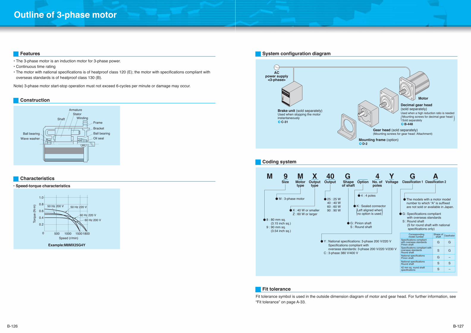
Features• The 3-phase motor is an induction motor for 3-phase power.• Continuous time rating• The motor with national specifications is of heatproof class 120 (E); the motor with specifications compliant with
overseas standards is of heatproof class 130 (B).
Note) 3-phase motor start-stop operation must not exceed 6-cycles per minute or damage may occur.
Construction
Characteristics• Speed-torque characteristics
StatorArmature
Shaft WindingFrameBracketBall bearingOil sealWave washer
Ball bearing
Example:M8MX25G4Y
Speed (r/min)0
1.0
0.8
0.6
0.4
0.2
1800
Torq
ue (N
·m)
15001000500
50 Hz 220 V50 Hz 200 V
60 Hz 220 V60 Hz 200 V
System configuration diagram
Coding system
Brake unit (sold separately)Used when stopping the motor instantaneously C-31
Motor
ACpower supply
<3-phase>
Mounting frame (option) D-2
M 9 M X 40 G 4 Y G A
8 : 80 mm sq. (3.15 inch sq.)9 : 90 mm sq. (3.54 inch sq.)
G: Pinion shaftS : Round shaft
X : 40 W or smallerZ : 60 W or larger
K : Sealed connector
Y : National specifications: 3-phase 200 V/220 V Specifications compliant with overseas standards: 3-phase 200 V/220 V/230 V
C : 3-phase 380 V/400 V
M : 3-phase motor 25 : 25 W40 : 40 W60 : 60 W90 : 90 W
4 : 4 poles
Size Motortype
Outputtype
Output Shapeof shaft
Option No. ofpoles
Voltage Classification 1 Classification 2
G: Specifications compliant with overseas standards
S : Round shaft (S for round shaft with national specifications only)
Left aligned when(no option is used )
Correspondingmodel number
Shape ofshaft Classification
Specifications compliantwith overseas standardsPinion shaftSpecifications compliant withoverseas standardsRound shaftNational specificationsPinion shaftNational specificationsRound shaft42 mm sq. round shaftspecifications
G
S
G
S
S
G
G
–
S
–
The models with a motor modelnumber to which “A” is suffixedare not sold or available in Japan.
Fit tolerance symbol is used in the outside dimension diagram of motor and gear head. For further information, see “Fit tolerance” on page A-33.
Fit tolerance
Gear head (sold separately)(Mounting screws for gear head: Attachment)
Decimal gear head (sold separately)Used when a high reduction ratio is needed
( ) B-448
Mounting screws for decimal gear head: Sold separately
B-127
B-128 B-129
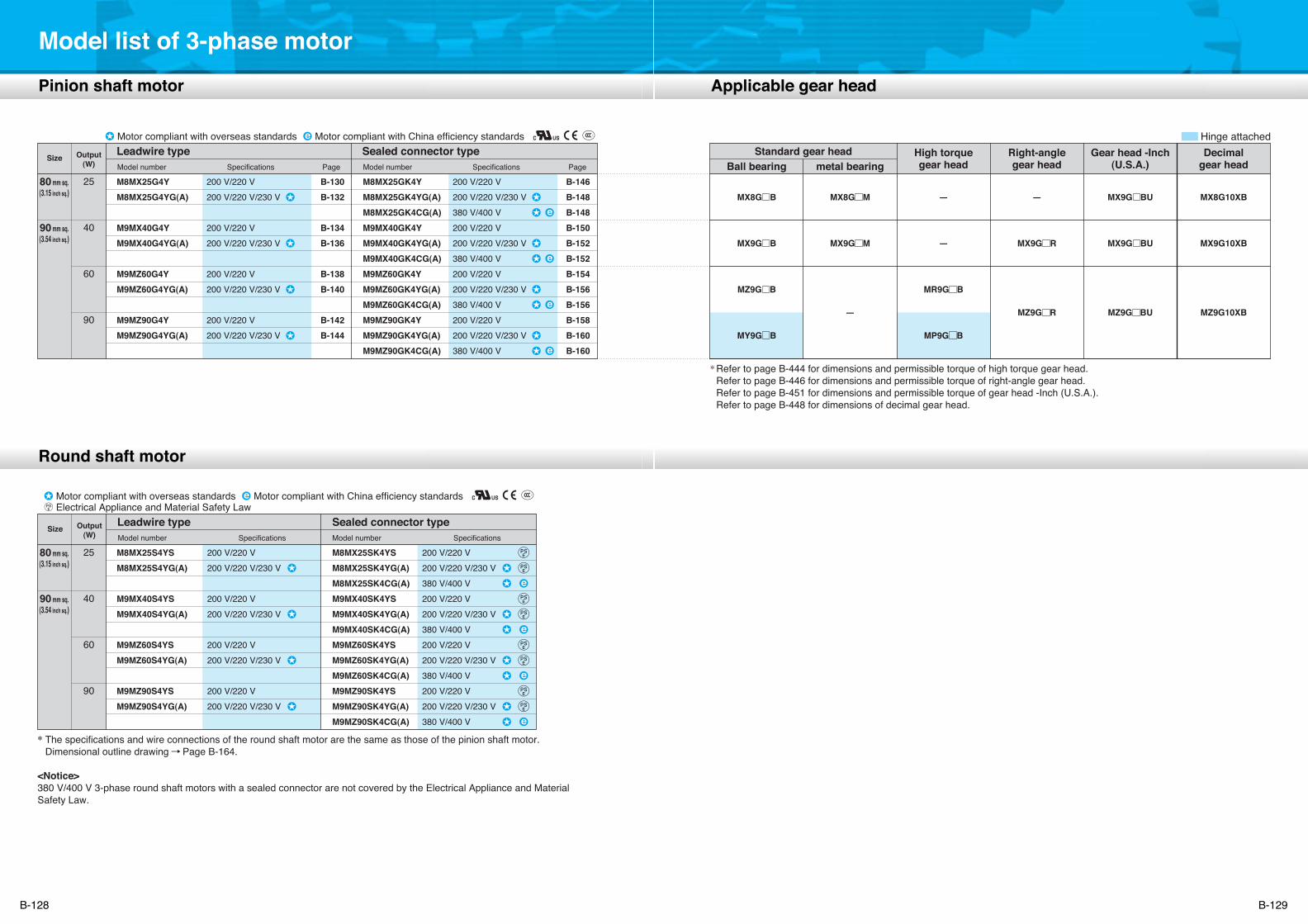
Model list of 3-phase motor
80 mm sq.(3.15 inch sq.)
90 mm sq.(3.54 inch sq.)
25
40
60
90
*Refer to page B-444 for dimensions and permissible torque of high torque gear head.Refer to page B-446 for dimensions and permissible torque of right-angle gear head.Refer to page B-451 for dimensions and permissible torque of gear head -Inch (U.S.A.).Refer to page B-448 for dimensions of decimal gear head.
M8MX25G4YM8MX25G4YG(A)
M9MX40G4YM9MX40G4YG(A)
M9MZ60G4YM9MZ60G4YG(A)
M9MZ90G4YM9MZ90G4YG(A)
200 V/220 V200 V/220 V/230 V
200 V/220 V200 V/220 V/230 V
200 V/220 V200 V/220 V/230 V
200 V/220 V200 V/220 V/230 V
B-130B-132
B-134B-136
B-138B-140
B-142B-144
M8MX25GK4YM8MX25GK4YG(A)M8MX25GK4CG(A)M9MX40GK4YM9MX40GK4YG(A)M9MX40GK4CG(A)M9MZ60GK4YM9MZ60GK4YG(A)M9MZ60GK4CG(A)M9MZ90GK4YM9MZ90GK4YG(A)M9MZ90GK4CG(A)
B-146B-148B-148B-150B-152B-152B-154B-156B-156B-158B-160B-160
MX8G B
MX9G B
MZ9G B
MY9G B
MX8G M
MX9G M
–
–
–
MR9G B
MP9G B
–
MX9G R
MZ9G
R
MX8G10XB
MX9G10XB
MZ9G10XB
80 mm sq.(3.15 inch sq.)
90 mm sq.(3.54 inch sq.)
25
40
60
90
M8MX25S4YSM8MX25S4YG(A)
M9MX40S4YSM9MX40S4YG(A)
M9MZ60S4YSM9MZ60S4YG(A)
M9MZ90S4YSM9MZ90S4YG(A)
200 V/220 V200 V/220 V/230 V
200 V/220 V200 V/220 V/230 V
200 V/220 V200 V/220 V/230 V
200 V/220 V200 V/220 V/230 V
M8MX25SK4YSM8MX25SK4YG(A)M8MX25SK4CG(A)M9MX40SK4YSM9MX40SK4YG(A)M9MX40SK4CG(A)M9MZ60SK4YSM9MZ60SK4YG(A)M9MZ60SK4CG(A)M9MZ90SK4YSM9MZ90SK4YG(A)M9MZ90SK4CG(A)
200 V/220 V200 V/220 V/230 V380 V/400 V200 V/220 V200 V/220 V/230 V380 V/400 V200 V/220 V200 V/220 V/230 V380 V/400 V200 V/220 V200 V/220 V/230 V380 V/400 V
200 V/220 V200 V/220 V/230 V380 V/400 V200 V/220 V200 V/220 V/230 V380 V/400 V200 V/220 V200 V/220 V/230 V380 V/400 V200 V/220 V200 V/220 V/230 V380 V/400 V
Output(W)
SizeLeadwire typeModel number Specifications Page
Sealed connector typeModel number Specifications Page
Hinge attachedStandard gear head
Ball bearing metal bearingDecimal
gear headHigh torquegear head
Right-anglegear head
MX9G BU
MX9G BU
MZ9G
BU
Gear head -Inch(U.S.A.)
Output(W)
SizeLeadwire typeModel number
Sealed connector typeModel number
Electrical Appliance and Material Safety Law
Specifications Specifications
* The specifications and wire connections of the round shaft motor are the same as those of the pinion shaft motor. Dimensional outline drawing Page B-164.
<Notice>380 V/400 V 3-phase round shaft motors with a sealed connector are not covered by the Electrical Appliance and Material Safety Law.
Motor compliant with overseas standards Motor compliant with China efficiency standards
Motor compliant with overseas standards Motor compliant with China efficiency standards
Applicable gear headPinion shaft motor
Round shaft motor
96.3(3.79)85(3.35) 11.3(0.44)
7(0.28) 2(0.08)
ø75h
7
80 mm sq.
4–ø5.5(ø0.22)
CWCCW
3 motor leadwires 300±30 mm (11.8±1.18 inch)AWG20
O-ring
ø94(ø3.70)
MAX
ø86(
ø3.3
9)
(3.15 inch sq.)
(ø2.
95h7
)
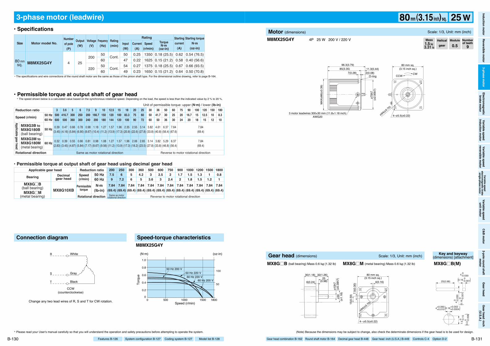
Change any two lead wires of R, S and T for CW rotation.
R
S
T
White
Gray
Black
CCW(counterclockwise)
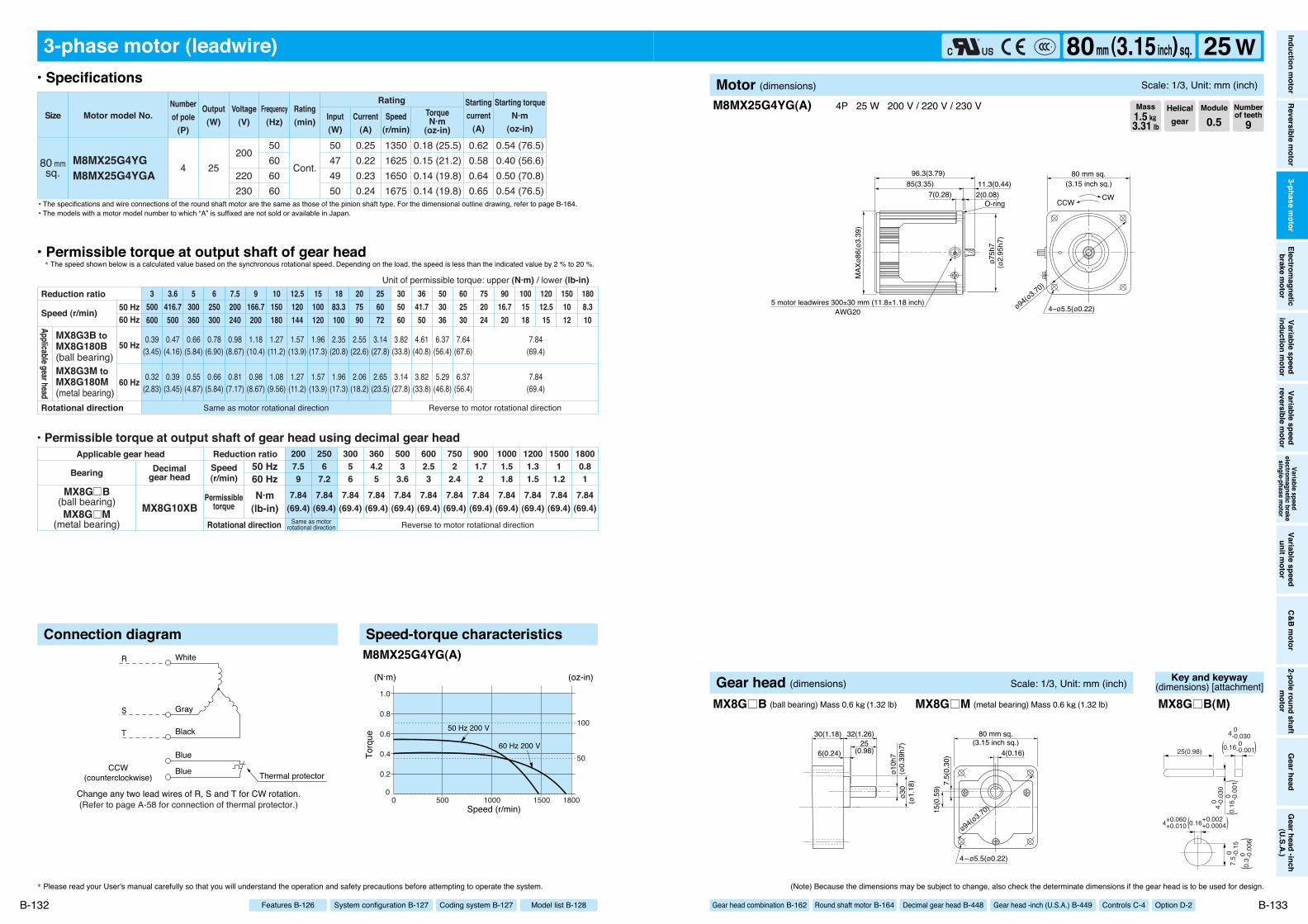
3-phase motor (leadwire)
80 mmsq. M8MX25G4Y
0.54 (76.5)0.40 (56.6)0.66 (93.5)0.50 (70.8)
0.18 (25.5)0.15 (21.2)0.18 (25.5)0.15 (21.2)
4 25200
220
50605060
50475449
0.250.220.270.23
1350162513751650
0.620.580.670.64
Cont.
Cont.
Motor model No.Rating
SizeNumberof pole
(P)
Output(W)
Voltage(V)
Frequency(Hz)
Rating(min) Input
(W)Current
(A)
TorqueN·m
(oz-in)
Starting torqueN·m
(oz-in)
Startingcurrent
(A)Speed
(r/min)
7.84(69.4)
7.84(69.4)
7.84(69.4)
7.84(69.4)
7.84(69.4)
7.84(69.4)
7.84(69.4)
7.84(69.4)
7.84(69.4)
7.84(69.4)
7.84(69.4)
7.84(69.4)
6002.53
5003
3.6
2506
7.2
30056
3604.25
2007.59
7502
2.4
9001.72
10001.51.8
12001.31.5
15001
1.2
18000.81
0.39(3.45)
0.47(4.16)
0.66(5.84)
0.78(6.90)
0.98(8.67)
1.18(10.4)
1.27(11.2)
1.57(13.9)
1.96(17.3)
2.35(20.8)
2.55(22.6)
3.14(27.8)
3.82(33.8)
4.61(40.8)
6.37(56.4)
7.64(67.6)
7.84(69.4)
0.32(2.83)
0.39(3.45)
0.55(4.87)
0.66(5.84)
0.81(7.17)
0.98(8.67)
1.08(9.56)
1.27(11.2)
1.57(13.9)
1.96(17.3)
2.06(18.2)
2.65(23.5)
3.14(27.8)
3.82(33.8)
5.29(46.8)
6.37(56.4)
7.84(69.4)
3500600
3.6416.7500
5300360
6250300
7.5200240
9166.7200
10150180
12.5120144
15100120
1883.3100
207590
256072
305060
3641.750
503036
602530
752024
9016.720
1001518
12012.515
1501012
1808.310
• Permissible torque at output shaft of gear head using decimal gear head
MX8G10XBSame as motor
rotational direction Reverse to motor rotational direction
MX8G B(ball bearing)MX8G M
(metal bearing)
Same as motor rotational direction Reverse to motor rotational direction
Applicable gear head
Bearing Decimalgear head
Speed(r/min)
Permissibletorque
50 Hz60 HzN·m
(lb-in)Rotational direction
Reduction ratio
Reduction ratio
Rotational direction
Speed (r/min)
Unit of permissible torque: upper (N·m) / lower (lb-in)!
MX8G3B toMX8G180B(ball bearing)MX8G3M toMX8G180M(metal bearing)
Applicable gear head
50 Hz60 Hz
50 Hz
60 Hz
Connection diagram Speed-torque characteristics
00 1800
1.0
0.8
0.6
0.4
0.2
15001000500
60 Hz 200 V60 Hz 220 V
50 Hz 200 V50 Hz 220 V
(N·m)
Speed (r/min)
Torq
ue
(oz-in)
100
50
M8MX25G4Y
M8MX25G4Y 4P 25 W 200 V / 220 V
* Please read your User's manual carefully so that you will understand the operation and safety precautions before attempting to operate the system. (Note) Because the dimensions may be subject to change, also check the determinate dimensions if the gear head is to be used for design.
B-130 B-131
• Specifications
• Permissible torque at output shaft of gear head* The speed shown below is a calculated value based on the synchronous rotational speed. Depending on the load, the speed is less than the indicated value by 2 % to 20 %.
• The specifications and wire connections of the round shaft motor are the same as those of the pinion shaft type. For the dimensional outline drawing, refer to page B-164.
Helicalgear
Module
0.5Numberof teeth
9Mass1.5 k""3.31 lb
Model list B-128Coding system B-127System configuration B-127Features B-126
Inductionm
otorReversible
motor
3-phasem
otorElectrom
agneticbrake
motor
Variablespeed
inductionm
otorVariable
speedreversible
motor
Variablespeed
electromagnetic
brakesingle-phase
motor
Variablespeed
unitmotor
C&Bm
otor2-pole
roundshaft
motor
Gearhead
Gearhead
-inch(U.S.A.)
80mm (3.15inch) sq. 25 WMotor (dimensions) Scale: 1/3, Unit: mm (inch)
Gear head combination B-162 Round shaft motor B-164 Decimal gear head B-448 Gear head -inch (U.S.A.) B-449 Controls C-4 Option D-2ø1
0h7
ø30
(ø1.
18)
(ø0.
39h7
)
7.5(
0.30
)15
(0.5
9)
4(0.16)
80 mm sq.(3.15 inch sq.)
ø94(ø3.70)
4–ø5.5(ø0.22)
30(1.18) 32(1.26)25
(0.98)6(0.24)
Gear head (dimensions) Scale: 1/3, Unit: mm (inch)
MX8G B (ball bearing) Mass 0.6 k"(1.32 lb) MX8G M (metal bearing) Mass 0.6 k"(1.32 lb)
Key and keyway(dimensions) [attachment]
25(0.98)
4 0 -0.
030
7.5 0
-
0.15
4 0 -0.030
0.16 0 -0.001
4+0.060 +0.010
( )
0.16
0
-0
.001
(
)
0.16+0.002 +0.0004( )
0.3 0
-
0.00
6(
)
MX8G B(M)
(Refer to page A-58 for connection of thermal protector.)
CCW(counterclockwise)
R
S
T
White
Gray
Black
Blue
Blue Thermal protector
Change any two lead wires of R, S and T for CW rotation.
3-phase motor (leadwire)
80 mmsq.
M8MX25G4YGM8MX25G4YGA
0.54 (76.5)0.40 (56.6)0.50 (70.8)0.54 (76.5)
0.18 (25.5)0.15 (21.2)0.14 (19.8)0.14 (19.8)
4 25
50606060
200
220230
50474950
0.250.220.230.24
1350162516501675
0.620.580.640.65
Cont.
Motor model No.Rating
SizeNumberof pole
(P)
Output(W)
Voltage(V)
Frequency(Hz)
Rating(min) Input
(W)Current
(A)
TorqueN·m
(oz-in)
Starting torqueN·m
(oz-in)
Startingcurrent
(A)Speed
(r/min)
7.84(69.4)
7.84(69.4)
7.84(69.4)
7.84(69.4)
7.84(69.4)
7.84(69.4)
7.84(69.4)
7.84(69.4)
7.84(69.4)
7.84(69.4)
7.84(69.4)
7.84(69.4)
6002.53
5003
3.6
2506
7.2
30056
3604.25
2007.59
7502
2.4
9001.72
10001.51.8
12001.31.5
15001
1.2
18000.81
0.39(3.45)
0.47(4.16)
0.66(5.84)
0.78(6.90)
0.98(8.67)
1.18(10.4)
1.27(11.2)
1.57(13.9)
1.96(17.3)
2.35(20.8)
2.55(22.6)
3.14(27.8)
3.82(33.8)
4.61(40.8)
6.37(56.4)
7.64(67.6)
7.84(69.4)
0.32(2.83)
0.39(3.45)
0.55(4.87)
0.66(5.84)
0.81(7.17)
0.98(8.67)
1.08(9.56)
1.27(11.2)
1.57(13.9)
1.96(17.3)
2.06(18.2)
2.65(23.5)
3.14(27.8)
3.82(33.8)
5.29(46.8)
6.37(56.4)
7.84(69.4)
3500600
3.6416.7500
5300360
6250300
7.5200240
9166.7200
10150180
12.5120144
15100120
1883.3100
207590
256072
305060
3641.750
503036
602530
752024
9016.720
1001518
12012.515
1501012
1808.310
• Permissible torque at output shaft of gear head using decimal gear head
MX8G10XBSame as motor
rotational direction Reverse to motor rotational direction
MX8G B(ball bearing)MX8G M
(metal bearing)
Same as motor rotational direction Reverse to motor rotational direction
Applicable gear head
Bearing Decimalgear head
Speed(r/min)
Permissibletorque
50 Hz60 HzN·m
(lb-in)Rotational direction
Reduction ratio
Reduction ratio
Rotational direction
Speed (r/min)
Unit of permissible torque: upper (N·m) / lower (lb-in)!
MX8G3B toMX8G180B(ball bearing)MX8G3M toMX8G180M(metal bearing)
Applicable gear head
50 Hz60 Hz
50 Hz
60 Hz
Connection diagram Speed-torque characteristics
00 1800
1.0
0.8
0.6
0.4
0.2
15001000500
(N·m)
Speed (r/min)
Torq
ue
(oz-in)
100
5060 Hz 200 V
50 Hz 200 V
M8MX25G4YG(A)
* Please read your User's manual carefully so that you will understand the operation and safety precautions before attempting to operate the system.
B-132
• Specifications
• Permissible torque at output shaft of gear head* The speed shown below is a calculated value based on the synchronous rotational speed. Depending on the load, the speed is less than the indicated value by 2 % to 20 %.
• The specifications and wire connections of the round shaft motor are the same as those of the pinion shaft type. For the dimensional outline drawing, refer to page B-164.
Model list B-128Coding system B-127System configuration B-127Features B-126
• The models with a motor model number to which “A” is suffixed are not sold or available in Japan.
96.3(3.79)85(3.35) 11.3(0.44)
7(0.28) 2(0.08)
ø75h
7
80 mm sq.
4–ø5.5(ø0.22)
CWCCW
5 motor leadwires 300±30 mm (11.8±1.18 inch)AWG20
O-ring
ø94(ø3.70)
MAX
ø86(
ø3.3
9)
(3.15 inch sq.)
(ø2.
95h7
)
M8MX25G4YG(A) 4P 25 W 200 V / 220 V / 230 V
(Note) Because the dimensions may be subject to change, also check the determinate dimensions if the gear head is to be used for design.
B-133
Helicalgear
Module
0.5Numberof teeth
9Mass1.5 k""3.31 lb
Inductionm
otorReversible
motor
3-phasem
otorElectrom
agneticbrake
motor
Variablespeed
inductionm
otorVariable
speedreversible
motor
Variablespeed
electromagnetic
brakesingle-phase
motor
Variablespeed
unitmotor
C&Bm
otor2-pole
roundshaft
motor
Gearhead
Gearhead
-inch(U.S.A.)
80mm (3.15inch) sq. 25 WMotor (dimensions) Scale: 1/3, Unit: mm (inch)
Gear head combination B-162 Round shaft motor B-164 Decimal gear head B-448 Gear head -inch (U.S.A.) B-449 Controls C-4 Option D-2ø1
0h7
ø30
(ø1.
18)
(ø0.
39h7
)
7.5(
0.30
)15
(0.5
9)
4(0.16)
80 mm sq.(3.15 inch sq.)
ø94(ø3.70)
4–ø5.5(ø0.22)
30(1.18) 32(1.26)25
(0.98)6(0.24)
Gear head (dimensions) Scale: 1/3, Unit: mm (inch)
MX8G B (ball bearing) Mass 0.6 k"(1.32 lb) MX8G M (metal bearing) Mass 0.6 k"(1.32 lb)
Key and keyway(dimensions) [attachment]
25(0.98)
4 0 -0.
030
7.5 0
-
0.15
4 0 -0.030
0.16 0 -0.001
4+0.060 +0.010
( )
0.16
0
-0
.001
(
)
0.16+0.002 +0.0004( )
0.3 0
-
0.00
6(
)
MX8G B(M)
117.8(4.64)105(4.13) 12.8(0.50)
7.5(0.30) 2(0.08)
ø85h
7
90 mm sq.
4–ø6.5(ø0.26)
CWCCW
3 motor leadwires 300±30 mm (11.8±1.18 inch)AWG20
ø104(ø4.09)
MAX
ø95(
ø3.7
4)
O-ring
(3.54 inch sq.)
(ø3.
35h7
)
Change any two lead wires of R, S and T for CW rotation.
R
S
T
White
Gray
Black
CCW(counterclockwise)
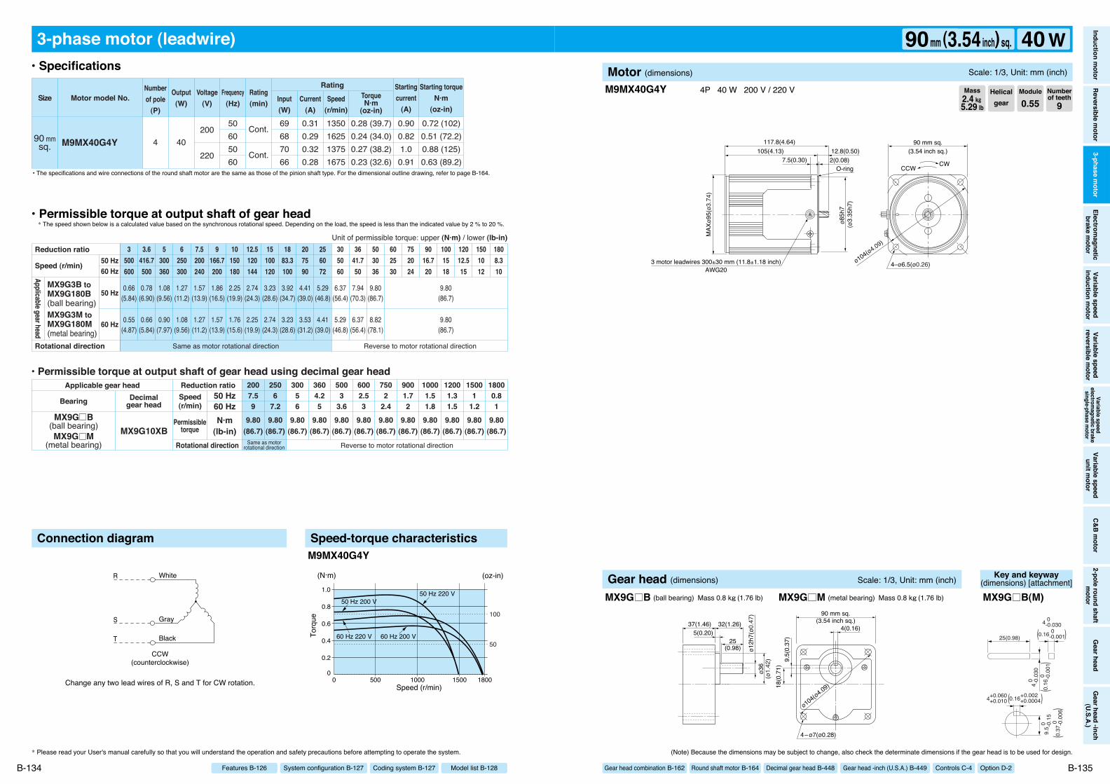
3-phase motor (leadwire)
90 mmsq. M9MX40G4Y
0.72 (102)0.51 (72.2)0.88 (125)0.63 (89.2)
0.28 (39.7)0.24 (34.0)0.27 (38.2)0.23 (32.6)
4 40200
220
50605060
69687066
0.310.290.320.28
1350162513751675
0.900.821.00.91
Cont.
Cont.
Motor model No.Rating
SizeNumberof pole
(P)
Output(W)
Voltage(V)
Frequency(Hz)
Rating(min) Input
(W)Current
(A)
TorqueN·m
(oz-in)
Starting torqueN·m
(oz-in)
Startingcurrent
(A)Speed
(r/min)
9.80(86.7)
9.80(86.7)
9.80(86.7)
9.80(86.7)
9.80(86.7)
9.80(86.7)
9.80(86.7)
9.80(86.7)
9.80(86.7)
9.80(86.7)
9.80(86.7)
9.80(86.7)
6002.53
5003
3.6
2506
7.2
30056
3604.25
2007.59
7502
2.4
9001.72
10001.51.8
12001.31.5
15001
1.2
18000.81
0.66(5.84)
0.78(6.90)
1.08(9.56)
1.27(11.2)
1.57(13.9)
1.86(16.5)
2.25(19.9)
2.74(24.3)
3.23(28.6)
3.92(34.7)
4.41(39.0)
5.29(46.8)
6.37(56.4)
7.94(70.3)
9.80(86.7)
9.80(86.7)
0.55(4.87)
0.66(5.84)
0.90(7.97)
1.08(9.56)
1.27(11.2)
1.57(13.9)
1.76(15.6)
2.25(19.9)
2.74(24.3)
3.23(28.6)
3.53(31.2)
4.41(39.0)
5.29(46.8)
6.37(56.4)
8.82(78.1)
9.80(86.7)
3500600
3.6416.7500
5300360
6250300
7.5200240
9166.7200
10150180
12.5120144
15100120
1883.3100
207590
256072
305060
3641.750
503036
602530
752024
9016.720
1001518
12012.515
1501012
1808.310
• Permissible torque at output shaft of gear head using decimal gear head
MX9G10XBSame as motor
rotational direction Reverse to motor rotational direction
MX9G B(ball bearing)MX9G M
(metal bearing)
Same as motor rotational direction Reverse to motor rotational direction
Applicable gear head
Bearing Decimalgear head
Speed(r/min)
Permissibletorque
50 Hz60 HzN·m
(lb-in)Rotational direction
Reduction ratio
Reduction ratio
Rotational direction
Speed (r/min)
Unit of permissible torque: upper (N·m) / lower (lb-in)
MX9G3B toMX9G180B(ball bearing)MX9G3M toMX9G180M(metal bearing)
Applicable gear head
50 Hz60 Hz
50 Hz
60 Hz
Connection diagram Speed-torque characteristics
00 1800
1.0
0.8
0.6
0.4
0.2
15001000500
60 Hz 200 V60 Hz 220 V
50 Hz 200 V50 Hz 220 V
(N·m)
Speed (r/min)
Torq
ue
(oz-in)
100
50
M9MX40G4Y
M9MX40G4Y 4P 40 W 200 V / 220 V
* Please read your User's manual carefully so that you will understand the operation and safety precautions before attempting to operate the system. (Note) Because the dimensions may be subject to change, also check the determinate dimensions if the gear head is to be used for design.
B-134 B-135
• Specifications
• Permissible torque at output shaft of gear head* The speed shown below is a calculated value based on the synchronous rotational speed. Depending on the load, the speed is less than the indicated value by 2 % to 20 %.
• The specifications and wire connections of the round shaft motor are the same as those of the pinion shaft type. For the dimensional outline drawing, refer to page B-164.
Helicalgear
Module
0.55Numberof teeth
9Mass2.4 k""5.29 lb
Model list B-128Coding system B-127System configuration B-127Features B-126
Inductionm
otorReversible
motor
3-phasem
otorElectrom
agneticbrake
motor
Variablespeed
inductionm
otorVariable
speedreversible
motor
Variablespeed
electromagnetic
brakesingle-phase
motor
Variablespeed
unitmotor
C&Bm
otor2-pole
roundshaft
motor
Gearhead
Gearhead
-inch(U.S.A.)
90mm (3.54inch) sq. 40 WMotor (dimensions) Scale: 1/3, Unit: mm (inch)
Gear head combination B-162 Round shaft motor B-164 Decimal gear head B-448 Gear head -inch (U.S.A.) B-449 Controls C-4 Option D-2
ø12h
7(ø0
.47)
ø36
(ø1.
42) 9.
5(0.
37)
18(0
.71)
4(0.16)
90 mm sq.(3.54 inch sq.)
ø104(ø4.09)
4–ø7(ø0.28)
37(1.46) 32(1.26)
25(0.98)
5(0.20)
Gear head (dimensions) Scale: 1/3, Unit: mm (inch)
MX9G B (ball bearing) Mass 0.8 k"(1.76 lb) MX9G M (metal bearing) Mass 0.8 k"(1.76 lb)
Key and keyway(dimensions) [attachment]
25(0.98)
4 0 -0.
030
9.5 0
-
0.15
4 0 -0.030
0.16 0 -0.001
4+0.060 +0.010
( )
0.16
0
-0
.001
(
)
0.16+0.002 +0.0004( )
0.37
0
-0
.006
(
)
MX9G B(M)
(Refer to page A-58 for connection of thermal protector.)
CCW(counterclockwise)
R
S
T
White
Gray
Black
Blue
Blue Thermal protector
Change any two lead wires of R, S and T for CW rotation.
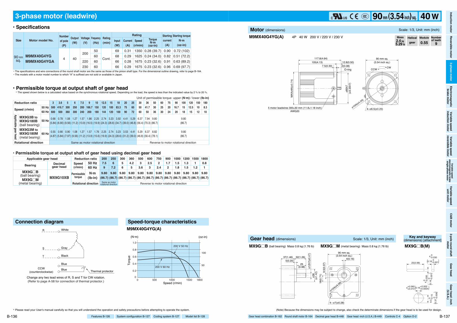
3-phase motor (leadwire)
90 mmsq.
M9MX40G4YGM9MX40G4YGA
0.72 (102)0.51 (72.2)0.63 (89.2)0.69 (97.7)
0.28 (39.7)0.24 (34.0)0.23 (32.6)0.23 (32.6)
4 40
50606060
200
220230
69686666
0.310.290.280.29
1350162516751675
0.900.820.910.96
Cont.
Motor model No.Rating
SizeNumberof pole
(P)
Output(W)
Voltage(V)
Frequency(Hz)
Rating(min) Input
(W)Current
(A)
TorqueN·m
(oz-in)
Starting torqueN·m
(oz-in)
Startingcurrent
(A)Speed
(r/min)
9.80(86.7)
9.80(86.7)
9.80(86.7)
9.80(86.7)
9.80(86.7)
9.80(86.7)
9.80(86.7)
9.80(86.7)
9.80(86.7)
9.80(86.7)
9.80(86.7)
9.80(86.7)
6002.53
5003
3.6
2506
7.2
30056
3604.25
2007.59
7502
2.4
9001.72
10001.51.8
12001.31.5
15001
1.2
18000.81
0.66(5.84)
0.78(6.90)
1.08(9.56)
1.27(11.2)
1.57(13.9)
1.86(16.5)
2.25(19.9)
2.74(24.3)
3.23(28.6)
3.92(34.7)
4.41(39.0)
5.29(46.8)
6.37(56.4)
7.94(70.3)
9.80(86.7)
9.80(86.7)
0.55(4.87)
0.66(5.84)
0.90(7.97)
1.08(9.56)
1.27(11.2)
1.57(13.9)
1.76(15.6)
2.25(19.9)
2.74(24.3)
3.23(28.6)
3.53(31.2)
4.41(39.0)
5.29(46.8)
6.37(56.4)
8.82(78.1)
9.80(86.7)
3500600
3.6416.7500
5300360
6250300
7.5200240
9166.7200
10150180
12.5120144
15100120
1883.3100
207590
256072
305060
3641.750
503036
602530
752024
9016.720
1001518
12012.515
1501012
1808.310
• Permissible torque at output shaft of gear head using decimal gear head
MX9G10XBSame as motor
rotational direction Reverse to motor rotational direction
MX9G B(ball bearing)MX9G M
(metal bearing)
Same as motor rotational direction Reverse to motor rotational direction
Applicable gear head
Bearing Decimalgear head
Speed(r/min)
Permissibletorque
50 Hz60 HzN·m
(lb-in)Rotational direction
Reduction ratio
Reduction ratio
Rotational direction
Speed (r/min)
Unit of permissible torque: upper (N·m) / lower (lb-in)
MX9G3B toMX9G180B(ball bearing)MX9G3M toMX9G180M(metal bearing)
Applicable gear head
50 Hz60 Hz
50 Hz
60 Hz
Connection diagram Speed-torque characteristics
00 1800
1.0
0.8
0.6
0.4
0.2
15001000500
(N·m)
Speed (r/min)
Torq
ue
(oz-in)
100
50200 V 60 Hz
200 V 50 Hz
M9MX40G4YG(A)
* Please read your User's manual carefully so that you will understand the operation and safety precautions before attempting to operate the system.
B-136
• Specifications
• Permissible torque at output shaft of gear head* The speed shown below is a calculated value based on the synchronous rotational speed. Depending on the load, the speed is less than the indicated value by 2 % to 20 %.
• The specifications and wire connections of the round shaft motor are the same as those of the pinion shaft type. For the dimensional outline drawing, refer to page B-164.
Model list B-128Coding system B-127System configuration B-127Features B-126
• The models with a motor model number to which “A” is suffixed are not sold or available in Japan.
117.8(4.64)105(4.13) 12.8(0.50)
7.5(0.30) 2(0.08)
ø85h
7
90 mm sq.
4–ø6.5(ø0.26)
CWCCW
5 motor leadwires 300±30 mm (11.8±1.18 inch)AWG20
ø104(ø4.09)
MAX
ø95(
ø3.7
4)
O-ring
(3.54 inch sq.)
(ø3.
35h7
)
M9MX40G4YG(A) 4P 40 W 200 V / 220 V / 230 V
(Note) Because the dimensions may be subject to change, also check the determinate dimensions if the gear head is to be used for design.
B-137
Helicalgear
Module
0.55Numberof teeth
9Mass2.4 k""5.29 lb
Inductionm
otorReversible
motor
3-phasem
otorElectrom
agneticbrake
motor
Variablespeed
inductionm
otorVariable
speedreversible
motor
Variablespeed
electromagnetic
brakesingle-phase
motor
Variablespeed
unitmotor
C&Bm
otor2-pole
roundshaft
motor
Gearhead
Gearhead
-inch(U.S.A.)
90mm (3.54inch) sq. 40 WMotor (dimensions) Scale: 1/3, Unit: mm (inch)
Gear head combination B-162 Round shaft motor B-164 Decimal gear head B-448 Gear head -inch (U.S.A.) B-449 Controls C-4 Option D-2
ø12h
7(ø0
.47)
ø36
(ø1.
42) 9.
5(0.
37)
18(0
.71)
4(0.16)
90 mm sq.(3.54 inch sq.)
ø104(ø4.09)
4–ø7(ø0.28)
37(1.46) 32(1.26)
25(0.98)
5(0.20)
Gear head (dimensions) Scale: 1/3, Unit: mm (inch)
MX9G B (ball bearing) Mass 0.8 k"(1.76 lb) MX9G M (metal bearing) Mass 0.8 k"(1.76 lb)
Key and keyway(dimensions) [attachment]
25(0.98)
4 0 -0.
030
9.5 0
-
0.15
4 0 -0.030
0.16 0 -0.001
4+0.060 +0.010
( )
0.16
0
-0
.001
(
)
0.16+0.002 +0.0004( )
0.37
0
-0
.006
(
)
MX9G B(M)
140.5(5.53)120(4.72) 20.5(0.81)
7.5(0.30)40(1.57) 2(0.08)
ø85h
7
CWCCW
3 motor leadwires 300±30 mm (11.8±1.18 inch)AWG20
92 m
m s
q.(3
.62
inch
sq.
)
4–ø6.5(ø0.26)ø104(ø4.09)
90 mm sq.(3.54 inch sq.)
(ø3.
35h7
)
O-ring
Change any two lead wires of R, S and T for CW rotation.
R
S
T
White
Gray
Black
CCW(counterclockwise)
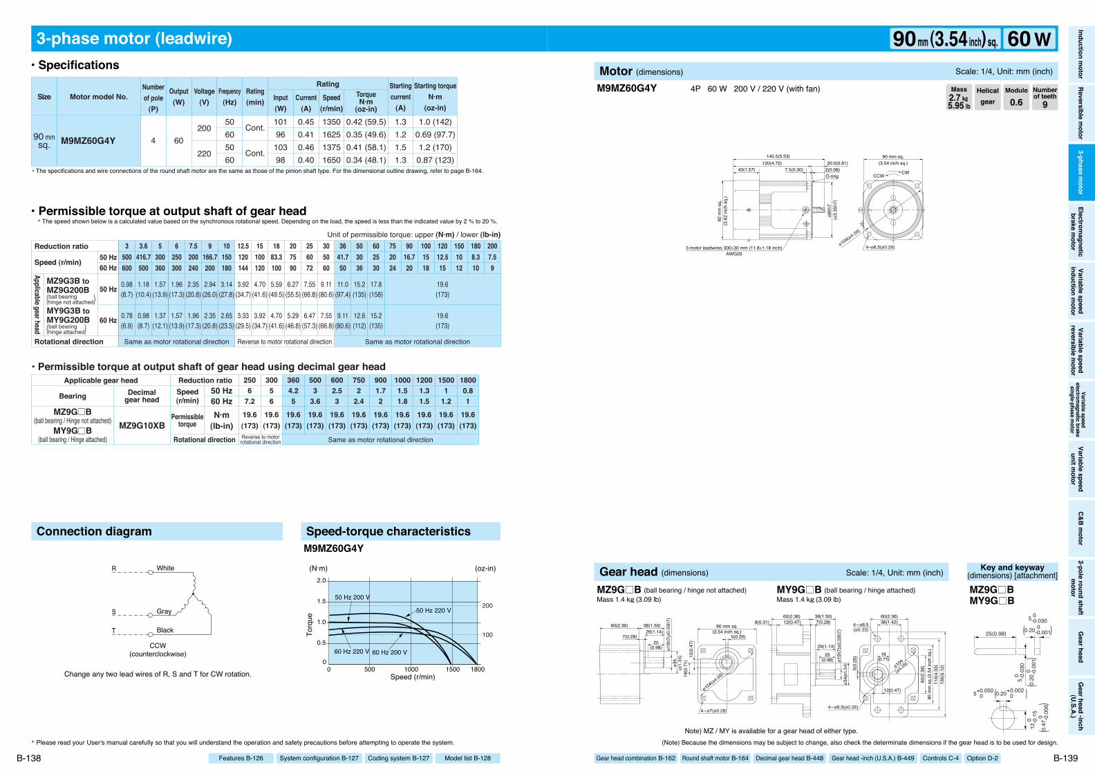
3-phase motor (leadwire)
90 mmsq. M9MZ60G4Y
1.0 (142)0.69 (97.7)1.2 (170)0.87 (123)
0.42 (59.5)0.35 (49.6)0.41 (58.1)0.34 (48.1)
4 60200
220
50605060
10196
10398
0.450.410.460.40
1350162513751650
1.31.21.51.3
Cont.
Cont.
Motor model No.Rating
SizeNumberof pole
(P)
Output(W)
Voltage(V)
Frequency(Hz)
Rating(min) Input
(W)Current
(A)
TorqueN·m
(oz-in)
Starting torqueN·m
(oz-in)
Startingcurrent
(A)Speed
(r/min)
Same as motor rotational direction
19.6(173)
19.6(173)
19.6(173)
19.6(173)
19.6(173)
19.6(173)
19.6(173)
19.6(173)
19.6(173)
19.6(173)
19.6(173)
6002.53
5003
3.6
2506
7.2
30056
3604.25
7502
2.4
9001.72
10001.51.8
12001.31.5
15001
1.2
18000.81
0.98(8.7)
1.18(10.4)
1.57(13.9)
1.96(17.3)
2.35(20.8)
2.94(26.0)
3.14(27.8)
3.92(34.7)
4.70(41.6)
5.59(49.5)
6.27(55.5)
7.55(66.8)
9.11(80.6)
11.0(97.4)
15.2(135)
17.8(158)
19.6(173)
0.78(6.9)
0.98(8.7)
1.37(12.1)
1.57(13.9)
1.96(17.3)
2.35(20.8)
2.65(23.5)
3.33(29.5)
3.92(34.7)
4.70(41.6)
5.29(46.8)
6.47(57.3)
7.55(66.8)
9.11(80.6)
12.6(112)
15.2(135)
19.6(173)
3500600
3.6416.7500
5300360
6250300
7.5200240
9166.7200
10150180
12.5120144
15100120
1883.3100
207590
256072
305060
3641.750
503036
602530
752024
9016.720
1001518
12012.515
1808.310
2007.59
1501012
Same as motor rotational direction Same as motor rotational directionReverse to motor rotational direction
Reverse to motorrotational direction
• Permissible torque at output shaft of gear head using decimal gear head
MZ9G10XBMZ9G B
(ball bearing / Hinge not attached)MY9G B
(ball bearing / Hinge attached)
Applicable gear head
Bearing Decimalgear head
Speed(r/min)
Permissibletorque
50 Hz60 HzN·m
(lb-in)Rotational direction
Reduction ratio
Reduction ratio
Rotational direction
Speed (r/min)
Unit of permissible torque: upper (N·m) / lower (lb-in)
MZ9G3B toMZ9G200B
MY9G3B toMY9G200B
Applicable gear head
ball bearing(hinge not attached)
ball bearing(hinge attached)
50 Hz60 Hz
50 Hz
60 Hz
Connection diagram Speed-torque characteristics
00 1800
2.0
1.5
1.0
0.5
15001000500
50 Hz 200 V
50 Hz 220 V
60 Hz 200 V60 Hz 220 V
(N·m)
Speed (r/min)
Torq
ue
(oz-in)
100
200
M9MZ60G4Y
M9MZ60G4Y 4P 60 W 200 V / 220 V (with fan)
* Please read your User's manual carefully so that you will understand the operation and safety precautions before attempting to operate the system. (Note) Because the dimensions may be subject to change, also check the determinate dimensions if the gear head is to be used for design.
B-138 B-139
• Specifications
• Permissible torque at output shaft of gear head* The speed shown below is a calculated value based on the synchronous rotational speed. Depending on the load, the speed is less than the indicated value by 2 % to 20 %.
• The specifications and wire connections of the round shaft motor are the same as those of the pinion shaft type. For the dimensional outline drawing, refer to page B-164.
Helicalgear
Module
0.6Numberof teeth
9Mass2.7 k""5.95 lb
Model list B-128Coding system B-127System configuration B-127Features B-126
Inductionm
otorReversible
motor
3-phasem
otorElectrom
agneticbrake
motor
Variablespeed
inductionm
otorVariable
speedreversible
motor
Variablespeed
electromagnetic
brakesingle-phase
motor
Variablespeed
unitmotor
C&Bm
otor2-pole
roundshaft
motor
Gearhead
Gearhead
-inch(U.S.A.)
90mm (3.54inch) sq. 60 WMotor (dimensions) Scale: 1/4, Unit: mm (inch)
Gear head combination B-162 Round shaft motor B-164 Decimal gear head B-448 Gear head -inch (U.S.A.) B-449 Controls C-4 Option D-2
Note) MZ / MY is available for a gear head of either type.
ø15h
7(ø0
.59h
7)ø3
4(ø
1.34
) 12(0
.47)
18(0
.71)
5(0.20)
90 mm sq.(3.54 inch sq.)
ø104(ø4.09)
4–ø7(ø0.28)
29(1.14)
25(0.98)
7(0.28)
60(2.36) 38(1.50)
5(0.
20)
ø34(
ø1.3
4)ø1
5h7(
ø0.5
9h7)
110(
4.33
)13
0(5.
12)
60(2.36)36(1.42)4–ø8.5
(ø0.33)
4–ø6.5(ø0.26)
60(2.36) 38(1.50)7(0.28)
29(1.14)
12(0.47)8(0.31)
25(0.98)
18(0.71)
12(0.47)
ø104
(ø4.09)
90 m
m s
q.(3
.54
inch
sq.
)60
(2.3
6)
Gear head (dimensions) Scale: 1/4, Unit: mm (inch)
MZ9G B (ball bearing / hinge not attached) MY9G B (ball bearing / hinge attached)Mass 1.4 k"(3.09 lb) Mass 1.4 k"(3.09 lb)
Key and keyway(dimensions) [attachment]
25(0.98)
5 0 -0.
030
12 0
-0
.15
5 0 -0.030
0.20 0 -0.001
5+0.050 0
( )
0.20
0
-0
.001
(
)
0.20+0.002 0( )
0.47
0
-0
.006
(
)
MZ9G BMY9G B

(Refer to page A-58 for connection of thermal protector.)
CCW(counterclockwise)
R
S
T
White
Gray
Black
Blue
Blue Thermal protector
Change any two lead wires of R, S and T for CW rotation.
3-phase motor (leadwire)
90 mmsq.
M9MZ60G4YGM9MZ60G4YGA
1.0 (142)0.69 (97.7)0.87 (123)1.0 (142)
0.42 (59.5)0.35 (49.6)0.35 (49.6)0.34 (48.1)
4 60
50606060
200
220230
101969898
0.450.410.400.41
1350162516501675
1.31.21.31.4
Cont.
Motor model No.Rating
SizeNumberof pole
(P)
Output(W)
Voltage(V)
Frequency(Hz)
Rating(min) Input
(W)Current
(A)
TorqueN·m
(oz-in)
Starting torqueN·m
(oz-in)
Startingcurrent
(A)Speed
(r/min)
Same as motor rotational direction
19.6(173)
19.6(173)
19.6(173)
19.6(173)
19.6(173)
19.6(173)
19.6(173)
19.6(173)
19.6(173)
19.6(173)
19.6(173)
6002.53
5003
3.6
2506
7.2
30056
3604.25
7502
2.4
9001.72
10001.51.8
12001.31.5
15001
1.2
18000.81
0.98(8.7)
1.18(10.4)
1.57(13.9)
1.96(17.3)
2.35(20.8)
2.94(26.0)
3.14(27.8)
3.92(34.7)
4.70(41.6)
5.59(49.5)
6.27(55.5)
7.55(66.8)
9.11(80.6)
11.0(97.4)
15.2(135)
17.8(158)
19.6(173)
0.78(6.9)
0.98(8.7)
1.37(12.1)
1.57(13.9)
1.96(17.3)
2.35(20.8)
2.65(23.5)
3.33(29.5)
3.92(34.7)
4.70(41.6)
5.29(46.8)
6.47(57.3)
7.55(66.8)
9.11(80.6)
12.6(112)
15.2(135)
19.6(173)
3500600
3.6416.7500
5300360
6250300
7.5200240
9166.7200
10150180
12.5120144
15100120
1883.3100
207590
256072
305060
3641.750
503036
602530
752024
9016.720
1001518
12012.515
1808.310
2007.59
1501012
Same as motor rotational direction Same as motor rotational directionReverse to motor rotational direction
Reverse to motorrotational direction
• Permissible torque at output shaft of gear head using decimal gear head
MZ9G10XBMZ9G B
(ball bearing / Hinge not attached)MY9G B
(ball bearing / Hinge attached)
Applicable gear head
Bearing Decimalgear head
Speed(r/min)
Permissibletorque
50 Hz60 HzN·m
(lb-in)Rotational direction
Reduction ratio
Reduction ratio
Rotational direction
Speed (r/min)
Unit of permissible torque: upper (N·m) / lower (lb-in)
MZ9G3B toMZ9G200B
MY9G3B toMY9G200B
Applicable gear head
ball bearing(hinge not attached)
ball bearing(hinge attached)
50 Hz60 Hz
50 Hz
60 Hz
Connection diagram Speed-torque characteristics
00 1800
1.5
1.0
0.5
15001000500
60 Hz 200 V
50 Hz 200 V
(N·m)
Speed (r/min)
Torq
ue
150
100
50
200
(oz-in)
M9MZ60G4YG(A)
* Please read your User's manual carefully so that you will understand the operation and safety precautions before attempting to operate the system.
B-140
• Specifications
• Permissible torque at output shaft of gear head* The speed shown below is a calculated value based on the synchronous rotational speed. Depending on the load, the speed is less than the indicated value by 2 % to 20 %.
• The specifications and wire connections of the round shaft motor are the same as those of the pinion shaft type. For the dimensional outline drawing, refer to page B-164.
Model list B-128Coding system B-127System configuration B-127Features B-126
• The models with a motor model number to which “A” is suffixed are not sold or available in Japan.
140.5(5.53)120(4.72) 20.5(0.81)
7.5(0.30)40(1.57) 2(0.08)
ø85h
7
CWCCW
5 motor leadwires 300±30 mm (11.8±1.18 inch)AWG20
92 m
m s
q.(3
.62
inch
sq.
)
4–ø6.5(ø0.26)ø104(ø4.09)
90 mm sq.(3.54 inch sq.)
(ø3.
35h7
)
O-ring
M9MZ60G4YG(A) 4P 60 W 200 V / 220 V / 230 V (with fan)
(Note) Because the dimensions may be subject to change, also check the determinate dimensions if the gear head is to be used for design.
B-141
Helicalgear
Module
0.6Numberof teeth
9Mass2.7 k""5.95 lb
Inductionm
otorReversible
motor
3-phasem
otorElectrom
agneticbrake
motor
Variablespeed
inductionm
otorVariable
speedreversible
motor
Variablespeed
electromagnetic
brakesingle-phase
motor
Variablespeed
unitmotor
C&Bm
otor2-pole
roundshaft
motor
Gearhead
Gearhead
-inch(U.S.A.)
90mm (3.54inch) sq. 60 WMotor (dimensions) Scale: 1/4, Unit: mm (inch)
Gear head combination B-162 Round shaft motor B-164 Decimal gear head B-448 Gear head -inch (U.S.A.) B-449 Controls C-4 Option D-2
Note) MZ / MY is available for a gear head of either type.
ø15h
7(ø0
.59h
7)ø3
4(ø
1.34
) 12(0
.47)
18(0
.71)
5(0.20)
90 mm sq.(3.54 inch sq.)
ø104(ø4.09)
4–ø7(ø0.28)
29(1.14)
25(0.98)
7(0.28)
60(2.36) 38(1.50)
5(0.
20)
ø34(
ø1.3
4)ø1
5h7(
ø0.5
9h7)
110(
4.33
)13
0(5.
12)
60(2.36)36(1.42)4–ø8.5
(ø0.33)
4–ø6.5(ø0.26)
60(2.36) 38(1.50)7(0.28)
29(1.14)
12(0.47)8(0.31)
25(0.98)
18(0.71)
12(0.47)
ø104
(ø4.09)
90 m
m s
q.(3
.54
inch
sq.
)60
(2.3
6)
Gear head (dimensions) Scale: 1/4, Unit: mm (inch)
MZ9G B (ball bearing / hinge not attached) MY9G B (ball bearing / hinge attached)Mass 1.4 k"(3.09 lb) Mass 1.4 k"(3.09 lb)
Key and keyway(dimensions) [attachment]
25(0.98)
5 0 -0.
030
12 0
-0
.15
5 0 -0.030
0.20 0 -0.001
5+0.050 0
( )
0.20
0
-0
.001
(
)
0.20+0.002 0( )
0.47
0
-0
.006
(
)
MZ9G BMY9G B
155.5(6.12)135(5.31) 20.5(0.81)
7.5(0.30)40(1.57) 2(0.08)
ø85h
7
92 m
m s
q.
3 motor leadwires 300±30 mm (11.8±1.18 inch)AWG20
CWCCW
(3.6
2 in
ch s
q.)
4–ø6.5(ø0.26)ø104(ø4.09)
90 mm sq.(3.54 inch sq.)
(ø3.
35h7
)
O-ring
Change any two lead wires of R, S and T for CW rotation.
R
S
T
White
Gray
Black
CCW(counterclockwise)
3-phase motor (leadwire)
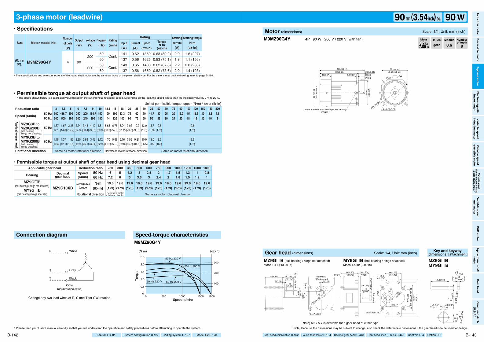
90 mmsq. M9MZ90G4Y
1.6 (227)1.1 (156)2.0 (283)1.4 (198)
0.63 (89.2)0.53 (75.1)0.62 (87.8)0.52 (73.6)
4 90200
220
50605060
141137143137
0.620.560.650.56
1350162514001650
2.01.82.22.0
Cont.
Cont.
Motor model No.Rating
SizeNumberof pole
(P)
Output(W)
Voltage(V)
Frequency(Hz)
Rating(min) Input
(W)Current
(A)
TorqueN·m
(oz-in)
Starting torqueN·m
(oz-in)
Startingcurrent
(A)Speed
(r/min)
19.6(173)
19.6(173)
19.6(173)
19.6(173)
19.6(173)
19.6(173)
19.6(173)
19.6(173)
19.6(173)
19.6(173)
19.6(173)
6002.53
5003
3.6
2506
7.2
30056
3604.25
7502
2.4
9001.72
10001.51.8
12001.31.5
15001
1.2
18000.81
1.18(10.4)
1.37(12.1)
1.86(16.5)
2.25(19.9)
2.84(25.1)
3.43(30.4)
3.72(32.9)
4.70(41.6)
5.68(50.3)
6.76(59.8)
7.55(66.8)
9.21(81.5)
10.9(96.5)
13.0(115)
18.3(162)
19.6(173)
1.37(12.1)
1.67(14.8)
2.25(19.9)
2.74(24.3)
3.43(30.4)
4.12(36.5)
4.51(39.9)
5.68(50.3)
6.76(59.8)
8.04(71.2)
9.02(79.8)
10.9(96.5)
13.0(115)
15.7(139)
19.6(173)
19.6(173)
3500600
3.6416.7500
5300360
6250300
7.5200240
9166.7200
10150180
12.5120144
15100120
1883.3100
207590
256072
305060
3641.750
503036
602530
752024
9016.720
1001518
12012.515
1808.310
2007.59
1501012
Same as motor rotational directionReverse to motorrotational direction
• Permissible torque at output shaft of gear head using decimal gear head
MZ9G10XBMZ9G B
(ball bearing / hinge not attached)MY9G B
(ball bearing / hinge attached)
Applicable gear head
Bearing Decimalgear head
Speed(r/min)
Permissibletorque
50 Hz60 HzN·m
(lb-in)Rotational direction
Reduction ratio
Same as motor rotational direction Same as motor rotational directionReverse to motor rotational direction
Reduction ratio
Rotational direction
Speed (r/min)
Unit of permissible torque: upper (N·m) / lower (lb-in)
MZ9G3B toMZ9G200B
MY9G3B toMY9G200B
Applicable gear head
ball bearing(hinge not attached)
ball bearing(hinge attached)
50 Hz60 Hz
50 Hz
60 Hz
Connection diagram Speed-torque characteristics
0
2.0
2.5
1.5
1.0
0.5
0 180015001000500
60 Hz 200 V60 Hz 220 V
50 Hz 200 V
50 Hz 220 V
Speed (r/min)
Torq
ue
(oz-in)
200
100
300
(N·m)
M9MZ90G4Y
M9MZ90G4Y 4P 90 W 200 V / 220 V (with fan)
* Please read your User's manual carefully so that you will understand the operation and safety precautions before attempting to operate the system. (Note) Because the dimensions may be subject to change, also check the determinate dimensions if the gear head is to be used for design.
B-142 B-143
• Specifications
• Permissible torque at output shaft of gear head* The speed shown below is a calculated value based on the synchronous rotational speed. Depending on the load, the speed is less than the indicated value by 2 % to 20 %.
• The specifications and wire connections of the round shaft motor are the same as those of the pinion shaft type. For the dimensional outline drawing, refer to page B-164.
Helicalgear
Module
0.6Numberof teeth
9Mass3.2 k""7.05 lb
Model list B-128Coding system B-127System configuration B-127Features B-126
Inductionm
otorReversible
motor
3-phasem
otorElectrom
agneticbrake
motor
Variablespeed
inductionm
otorVariable
speedreversible
motor
Variablespeed
electromagnetic
brakesingle-phase
motor
Variablespeed
unitmotor
C&Bm
otor2-pole
roundshaft
motor
Gearhead
Gearhead
-inch(U.S.A.)
90mm (3.54inch) sq. 90 WMotor (dimensions) Scale: 1/4, Unit: mm (inch)
Gear head combination B-162 Round shaft motor B-164 Decimal gear head B-448 Gear head -inch (U.S.A.) B-449 Controls C-4 Option D-2
Note) MZ / MY is available for a gear head of either type.
ø15h
7(ø0
.59h
7)ø3
4(ø
1.34
) 12(0
.47)
18(0
.71)
5(0.20)
90 mm sq.(3.54 inch sq.)
ø104(ø4.09)
4–ø7(ø0.28)
29(1.14)
25(0.98)
7(0.28)
60(2.36) 38(1.50)
5(0.
20)
ø34(
ø1.3
4)ø1
5h7(
ø0.5
9h7)
110(
4.33
)13
0(5.
12)
60(2.36)36(1.42)4–ø8.5
(ø0.33)
4–ø6.5(ø0.26)
60(2.36) 38(1.50)7(0.28)
29(1.14)
12(0.47)8(0.31)
25(0.98)
18(0.71)
12(0.47)
ø104
(ø4.09)
90 m
m s
q.(3
.54
inch
sq.
)60
(2.3
6)
Gear head (dimensions) Scale: 1/4, Unit: mm (inch)
MZ9G B (ball bearing / hinge not attached) MY9G B (ball bearing / hinge attached)Mass 1.4 k"(3.09 lb) Mass 1.4 k"(3.09 lb)
Key and keyway(dimensions) [attachment]
25(0.98)
5 0 -0.
030
12 0
-0
.15
5 0 -0.030
0.20 0 -0.001
5+0.050 0
( )
0.20
0
-0
.001
(
)
0.20+0.002 0( )
0.47
0
-0
.006
(
)
MZ9G BMY9G B
(Refer to page A-58 for connection of thermal protector.)
CCW(counterclockwise)
R
S
T
White
Gray
Black
Blue
Blue Thermal protector
Change any two lead wires of R, S and T for CW rotation.
3-phase motor (leadwire)
90 mmsq.
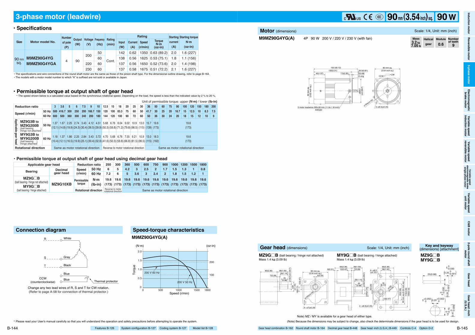
M9MZ90G4YGM9MZ90G4YGA
1.6 (227)1.1 (156)1.4 (198)1.6 (227)
0.63 (89.2)0.53 (75.1)0.52 (73.6)0.51 (72.2)
4 90
50606060
200
220230
142138137137
0.620.560.560.58
1350162516501675
2.01.82.02.1
Cont.
Motor model No.Rating
SizeNumberof pole
(P)
Output(W)
Voltage(V)
Frequency(Hz)
Rating(min) Input
(W)Current
(A)
TorqueN·m
(oz-in)
Starting torqueN·m
(oz-in)
Startingcurrent
(A)Speed
(r/min)
19.6(173)
19.6(173)
19.6(173)
19.6(173)
19.6(173)
19.6(173)
19.6(173)
19.6(173)
19.6(173)
19.6(173)
19.6(173)
6002.53
5003
3.6
2506
7.2
30056
3604.25
7502
2.4
9001.72
10001.51.8
12001.31.5
15001
1.2
18000.81
1.18(10.4)
1.37(12.1)
1.86(16.5)
2.25(19.9)
2.84(25.1)
3.43(30.4)
3.72(32.9)
4.70(41.6)
5.68(50.3)
6.76(59.8)
7.55(66.8)
9.21(81.5)
10.9(96.5)
13.0(115)
18.3(162)
19.6(173)
1.37(12.1)
1.67(14.8)
2.25(19.9)
2.74(24.3)
3.43(30.4)
4.12(36.5)
4.51(39.9)
5.68(50.3)
6.76(59.8)
8.04(71.2)
9.02(79.8)
10.9(96.5)
13.0(115)
15.7(139)
19.6(173)
19.6(173)
3500600
3.6416.7500
5300360
6250300
7.5200240
9166.7200
10150180
12.5120144
15100120
1883.3100
207590
256072
305060
3641.750
503036
602530
752024
9016.720
1001518
12012.515
1808.310
2007.59
1501012
Same as motor rotational directionReverse to motorrotational direction
• Permissible torque at output shaft of gear head using decimal gear head
MZ9G10XBMZ9G B
(ball bearing / hinge not attached)MY9G B
(ball bearing / hinge attached)
Applicable gear head
Bearing Decimalgear head
Speed(r/min)
Permissibletorque
50 Hz60 HzN·m
(lb-in)Rotational direction
Reduction ratio
Same as motor rotational direction Same as motor rotational directionReverse to motor rotational direction
Reduction ratio
Rotational direction
Speed (r/min)
Unit of permissible torque: upper (N·m) / lower (lb-in)
MZ9G3B toMZ9G200B
MY9G3B toMY9G200B
Applicable gear head
ball bearing(hinge not attached)
ball bearing(hinge attached)
50 Hz60 Hz
50 Hz
60 Hz
Connection diagram Speed-torque characteristics
00 1800
2.0
1.5
1.0
0.5
15001000500
200 V 60 Hz
200 V 50 Hz
(N·m)
Speed (r/min)
Torq
ue
(oz-in)
100
200
M9MZ90G4YG(A)
* Please read your User's manual carefully so that you will understand the operation and safety precautions before attempting to operate the system.
B-144
• Specifications
• Permissible torque at output shaft of gear head* The speed shown below is a calculated value based on the synchronous rotational speed. Depending on the load, the speed is less than the indicated value by 2 % to 20 %.
• The specifications and wire connections of the round shaft motor are the same as those of the pinion shaft type. For the dimensional outline drawing, refer to page B-164.
Model list B-128Coding system B-127System configuration B-127Features B-126
• The models with a motor model number to which “A” is suffixed are not sold or available in Japan.
155.5(6.12)135(5.31) 20.5(0.81)
7.5(0.30)40(1.57) 2(0.08)
ø85h
7
92 m
m s
q.
5 motor leadwires 300±30 mm (11.8±1.18 inch)AWG20
CWCCW
(3.6
2 in
ch s
q.)
4–ø6.5(ø0.26)ø104(ø4.09)
90 mm sq.(3.54 inch sq.)
(ø3.
35h7
)
O-ring
M9MZ90G4YG(A) 4P 90 W 200 V / 220 V / 230 V (with fan)
(Note) Because the dimensions may be subject to change, also check the determinate dimensions if the gear head is to be used for design.
B-145
Helicalgear
Module
0.6Numberof teeth
9Mass3.2 k""7.05 lb
Inductionm
otorReversible
motor
3-phasem
otorElectrom
agneticbrake
motor
Variablespeed
inductionm
otorVariable
speedreversible
motor
Variablespeed
electromagnetic
brakesingle-phase
motor
Variablespeed
unitmotor
C&Bm
otor2-pole
roundshaft
motor
Gearhead
Gearhead
-inch(U.S.A.)
90mm (3.54inch) sq. 90 WMotor (dimensions) Scale: 1/4, Unit: mm (inch)
Gear head combination B-162 Round shaft motor B-164 Decimal gear head B-448 Gear head -inch (U.S.A.) B-449 Controls C-4 Option D-2
Note) MZ / MY is available for a gear head of either type.
ø15h
7(ø0
.59h
7)ø3
4(ø
1.34
) 12(0
.47)
18(0
.71)
5(0.20)
90 mm sq.(3.54 inch sq.)
ø104(ø4.09)
4–ø7(ø0.28)
29(1.14)
25(0.98)
7(0.28)
60(2.36) 38(1.50)
5(0.
20)
ø34(
ø1.3
4)ø1
5h7(
ø0.5
9h7)
110(
4.33
)13
0(5.
12)
60(2.36)36(1.42)4–ø8.5
(ø0.33)
4–ø6.5(ø0.26)
60(2.36) 38(1.50)7(0.28)
29(1.14)
12(0.47)8(0.31)
25(0.98)
18(0.71)
12(0.47)
ø104
(ø4.09)
90 m
m s
q.(3
.54
inch
sq.
)60
(2.3
6)
Gear head (dimensions) Scale: 1/4, Unit: mm (inch)
MZ9G B (ball bearing / hinge not attached) MY9G B (ball bearing / hinge attached)Mass 1.4 k"(3.09 lb) Mass 1.4 k"(3.09 lb)
Key and keyway(dimensions) [attachment]
25(0.98)
5 0 -0.
030
12 0
-0
.15
5 0 -0.030
0.20 0 -0.001
5+0.050 0
( )
0.20
0
-0
.001
(
)
0.20+0.002 0( )
0.47
0
-0
.006
(
)
MZ9G BMY9G B

96.3(3.79)85(3.35)
75(2.95) 1(0.04)30(1.18)max.
11.3(0.44)7(0.28) 2(0.08)
ø75h
7
80 mm sq.(3.15 inch sq.)
ø94(ø3.70)
CCWCW
67(2.64)
MAX
ø86(
ø3.3
9)(2
0(0.
79))
(45(
1.77
))
4–ø5.5(ø0.22)
O-ring
(ø2.
95h7
)
Change any two lead wires of U, V and W for CW rotation.
R
S
T
White
Gray
Black
CCW(counterclockwise)
UV
W
Terminal
Screws for earth
W
V
U
3-phase motor (sealed connector)
80 mmsq. M8MX25GK4Y
0.54 (76.5)0.40 (56.6)0.66 (93.5)0.50 (70.8)
0.18 (25.5)0.15 (21.2)0.18 (25.5)0.15 (21.2)
4 25200
220
50605060
50475449
0.250.220.270.23
1350162513751650
0.620.580.670.64
Cont.
Cont.
Motor model No.Rating
SizeNumberof pole
(P)
Output(W)
Voltage(V)
Frequency(Hz)
Rating(min) Input
(W)Current
(A)
TorqueN·m
(oz-in)
Starting torqueN·m
(oz-in)
Startingcurrent
(A)Speed
(r/min)
7.84(69.4)
7.84(69.4)
7.84(69.4)
7.84(69.4)
7.84(69.4)
7.84(69.4)
7.84(69.4)
7.84(69.4)
7.84(69.4)
7.84(69.4)
7.84(69.4)
7.84(69.4)
6002.53
5003
3.6
2506
7.2
30056
3604.25
2007.59
7502
2.4
9001.72
10001.51.8
12001.31.5
15001
1.2
18000.81
0.39(3.45)
0.47(4.16)
0.66(5.84)
0.78(6.90)
0.98(8.67)
1.18(10.4)
1.27(11.2)
1.57(13.9)
1.96(17.3)
2.35(20.8)
2.55(22.6)
3.14(27.8)
3.82(33.8)
4.61(40.8)
6.37(56.4)
7.64(67.6)
7.84(69.4)
0.32(2.83)
0.39(3.45)
0.55(4.87)
0.66(5.84)
0.81(7.17)
0.98(8.67)
1.08(9.56)
1.27(11.2)
1.57(13.9)
1.96(17.3)
2.06(18.2)
2.65(23.5)
3.14(27.8)
3.82(33.8)
5.29(46.8)
6.37(56.4)
7.84(69.4)
3500600
3.6416.7500
5300360
6250300
7.5200240
9166.7200
10150180
12.5120144
15100120
1883.3100
207590
256072
305060
3641.750
503036
602530
752024
9016.720
1001518
12012.515
1501012
1808.310
• Permissible torque at output shaft of gear head using decimal gear head
MX8G10XBSame as motor
rotational direction Reverse to motor rotational direction
MX8G B(ball bearing)MX8G M
(metal bearing)
Same as motor rotational direction Reverse to motor rotational direction
Applicable gear head
Bearing Decimalgear head
Speed(r/min)
Permissibletorque
50 Hz60 HzN·m
(lb-in)Rotational direction
Reduction ratio
Reduction ratio
Rotational direction
Speed (r/min)
Unit of permissible torque: upper (N·m) / lower (lb-in)!
MX8G3B toMX8G180B(ball bearing)MX8G3M toMX8G180M(metal bearing)
Applicable gear head
50 Hz60 Hz
50 Hz
60 Hz
Connection diagram Speed-torque characteristics
00 1800
1.0
0.8
0.6
0.4
0.2
15001000500
60 Hz 200 V
60 Hz 220 V50 Hz 200 V 50 Hz 220 V
(N·m)
Speed (r/min)
Torq
ue
(oz-in)
100
50
M8MX25GK4Y
M8MX25GK4Y 4P 25 W 200 V / 220 V
* Please read your User's manual carefully so that you will understand the operation and safety precautions before attempting to operate the system. (Note) Because the dimensions may be subject to change, also check the determinate dimensions if the gear head is to be used for design.
B-146 B-147
• Specifications
• Permissible torque at output shaft of gear head* The speed shown below is a calculated value based on the synchronous rotational speed. Depending on the load, the speed is less than the indicated value by 2 % to 20 %.
• The specifications and wire connections of the round shaft motor are the same as those of the pinion shaft type. For the dimensional outline drawing, refer to page B-165.
* Diameter of applicable cabtyre cable to be ø8(ø0.31) to ø12(ø0.47).
Helicalgear
Module
0.5Numberof teeth
9Mass1.8 k""3.97 lb
Model list B-128Coding system B-127System configuration B-127Features B-126
Inductionm
otorReversible
motor
3-phasem
otorElectrom
agneticbrake
motor
Variablespeed
inductionm
otorVariable
speedreversible
motor
Variablespeed
electromagnetic
brakesingle-phase
motor
Variablespeed
unitmotor
C&Bm
otor2-pole
roundshaft
motor
Gearhead
Gearhead
-inch(U.S.A.)
80mm (3.15inch) sq. 25 WMotor (dimensions) Scale: 1/3, Unit: mm (inch)
Gear head combination B-163 Round shaft motor B-165 Decimal gear head B-448 Gear head -inch (U.S.A.) B-449 Controls C-4 Option D-2ø1
0h7
ø30
(ø1.
18)
(ø0.
39h7
)
7.5(
0.30
)15
(0.5
9)
4(0.16)
80 mm sq.(3.15 inch sq.)
ø94(ø3.70)
4–ø5.5(ø0.22)
30(1.18) 32(1.26)25
(0.98)6(0.24)
Gear head (dimensions) Scale: 1/3, Unit: mm (inch)
MX8G B (ball bearing) Mass 0.6 k"(1.32 lb) MX8G M (metal bearing) Mass 0.6 k"(1.32 lb)
Key and keyway(dimensions) [attachment]
25(0.98)
4 0 -0.
030
7.5 0
-
0.15
4 0 -0.030
0.16 0 -0.001
4+0.060 +0.010
( )
0.16
0
-0
.001
(
)
0.16+0.002 +0.0004( )
0.3 0
-
0.00
6(
)
MX8G B(M)
96.3(3.79)85(3.35)
75(2.95) 1(0.04)30(1.18)max.
11.3(0.44)7(0.28) 2(0.08)
ø75h
7
80 mm sq.(3.15 inch sq.)
ø94(ø3.70)
CCWCW
67(2.64)
MAX
ø86(
ø3.3
9)(2
0(0.
79))
(45(
1.77
))
4–ø5.5(ø0.22)
O-ring
(ø2.
95h7
)
(Refer to page A-58 for connection of thermal protector.)
PP
UV
W
Change any two lead wires of U, V and W for CW rotation.CCW (counterclockwise)
R
S
T
White
Gray
Black Thermal protectorBlue
Blue
Terminal
Screws for earth
W
V
U
P
P
3-phase motor (sealed connector)
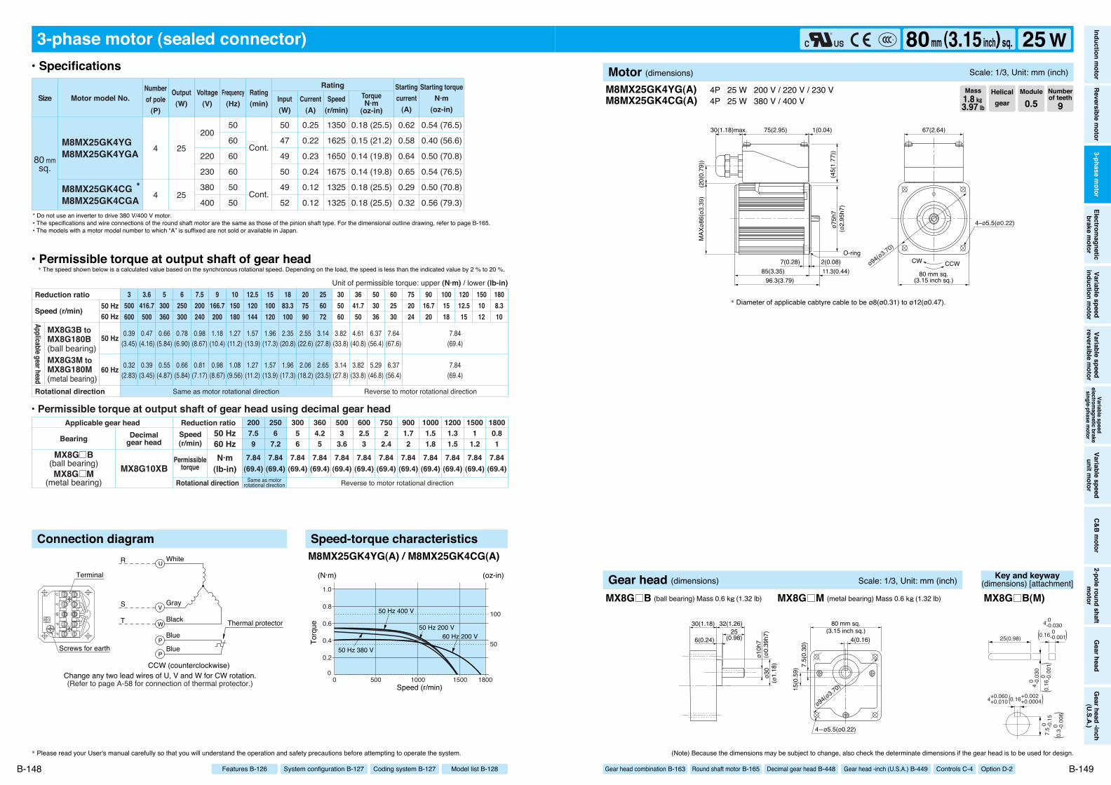
M8MX25GK4YGM8MX25GK4YGA
M8MX25GK4CG *M8MX25GK4CGA
0.54 (76.5)
0.40 (56.6)
0.50 (70.8)
0.54 (76.5)
0.50 (70.8)
0.56 (79.3)
0.18 (25.5)
0.15 (21.2)
0.14 (19.8)
0.14 (19.8)
0.18 (25.5)
0.18 (25.5)
80 mmsq.
4
4
25
25
50
60
60
60
50
50
200
220
230
380
400
50
47
49
50
49
52
0.25
0.22
0.23
0.24
0.12
0.12
1350
1625
1650
1675
1325
1325
0.62
0.58
0.64
0.65
0.29
0.32
Cont.
Cont.
Motor model No.Rating
SizeNumberof pole
(P)
Output(W)
Voltage(V)
Frequency(Hz)
Rating(min) Input
(W)Current
(A)
TorqueN·m
(oz-in)
Starting torqueN·m
(oz-in)
Startingcurrent
(A)Speed
(r/min)
7.84(69.4)
7.84(69.4)
7.84(69.4)
7.84(69.4)
7.84(69.4)
7.84(69.4)
7.84(69.4)
7.84(69.4)
7.84(69.4)
7.84(69.4)
7.84(69.4)
7.84(69.4)
6002.53
5003
3.6
2506
7.2
30056
3604.25
2007.59
7502
2.4
9001.72
10001.51.8
12001.31.5
15001
1.2
18000.81
0.39(3.45)
0.47(4.16)
0.66(5.84)
0.78(6.90)
0.98(8.67)
1.18(10.4)
1.27(11.2)
1.57(13.9)
1.96(17.3)
2.35(20.8)
2.55(22.6)
3.14(27.8)
3.82(33.8)
4.61(40.8)
6.37(56.4)
7.64(67.6)
7.84(69.4)
0.32(2.83)
0.39(3.45)
0.55(4.87)
0.66(5.84)
0.81(7.17)
0.98(8.67)
1.08(9.56)
1.27(11.2)
1.57(13.9)
1.96(17.3)
2.06(18.2)
2.65(23.5)
3.14(27.8)
3.82(33.8)
5.29(46.8)
6.37(56.4)
7.84(69.4)
3500600
3.6416.7500
5300360
6250300
7.5200240
9166.7200
10150180
12.5120144
15100120
1883.3100
207590
256072
305060
3641.750
503036
602530
752024
9016.720
1001518
12012.515
1501012
1808.310
Same as motor rotational direction Reverse to motor rotational direction
Reduction ratio
Rotational direction
Speed (r/min)
Unit of permissible torque: upper (N·m) / lower (lb-in)
MX8G3B toMX8G180B(ball bearing)MX8G3M toMX8G180M(metal bearing)
Applicable gear head
• Permissible torque at output shaft of gear head using decimal gear head
MX8G10XBSame as motor
rotational direction Reverse to motor rotational direction
MX8G B(ball bearing)MX8G M
(metal bearing)
Applicable gear head
Bearing Decimalgear head
Speed(r/min)
Permissibletorque
50 Hz60 HzN·m
(lb-in)Rotational direction
Reduction ratio
50 Hz60 Hz
50 Hz
60 Hz
Connection diagram Speed-torque characteristics
00 1800
1.0
0.8
0.6
0.4
0.2
15001000500
(N·m)
Speed (r/min)
Torq
ue
(oz-in)
100
5060 Hz 200 V
50 Hz 400 V
50 Hz 200 V
50 Hz 380 V
M8MX25GK4YG(A) / M8MX25GK4CG(A)
M8MX25GK4YG(A)M8MX25GK4CG(A)
4P 25 W 200 V / 220 V / 230 V4P 25 W 380 V / 400 V
* Diameter of applicable cabtyre cable to be ø8(ø0.31) to ø12(ø0.47).
* Please read your User's manual carefully so that you will understand the operation and safety precautions before attempting to operate the system. (Note) Because the dimensions may be subject to change, also check the determinate dimensions if the gear head is to be used for design.
B-148 B-149
• Specifications
• Permissible torque at output shaft of gear head* The speed shown below is a calculated value based on the synchronous rotational speed. Depending on the load, the speed is less than the indicated value by 2 % to 20 %.
* Do not use an inverter to drive 380 V/400 V motor.• The specifications and wire connections of the round shaft motor are the same as those of the pinion shaft type. For the dimensional outline drawing, refer to page B-165.• The models with a motor model number to which “A” is suffixed are not sold or available in Japan.
Helicalgear
Module
0.5Numberof teeth
9Mass1.8 k""3.97 lb
Model list B-128Coding system B-127System configuration B-127Features B-126
Inductionm
otorReversible
motor
3-phasem
otorElectrom
agneticbrake
motor
Variablespeed
inductionm
otorVariable
speedreversible
motor
Variablespeed
electromagnetic
brakesingle-phase
motor
Variablespeed
unitmotor
C&Bm
otor2-pole
roundshaft
motor
Gearhead
Gearhead
-inch(U.S.A.)
80mm (3.15inch) sq. 25 WMotor (dimensions) Scale: 1/3, Unit: mm (inch)
Gear head combination B-163 Round shaft motor B-165 Decimal gear head B-448 Gear head -inch (U.S.A.) B-449 Controls C-4 Option D-2ø1
0h7
ø30
(ø1.
18)
(ø0.
39h7
)
7.5(
0.30
)15
(0.5
9)
4(0.16)
80 mm sq.(3.15 inch sq.)
ø94(ø3.70)
4–ø5.5(ø0.22)
30(1.18) 32(1.26)25
(0.98)6(0.24)
Gear head (dimensions) Scale: 1/3, Unit: mm (inch)
MX8G B (ball bearing) Mass 0.6 k"(1.32 lb) MX8G M (metal bearing) Mass 0.6 k"(1.32 lb)
Key and keyway(dimensions) [attachment]
25(0.98)
4 0 -0.
030
7.5 0
-
0.15
4 0 -0.030
0.16 0 -0.001
4+0.060 +0.010
( )
0.16
0
-0
.001
(
)
0.16+0.002 +0.0004( )
0.3 0
-
0.00
6(
)
MX8G B(M)

ø85h
7(4
5(1.
77))
117.8(4.64)105(4.13) 12.8(0.50)
7.5(0.30) 2(0.08)
75(2.95) 1(0.04)30(1.18)max.
MAX
ø95(
ø3.7
4)(2
0(0.
79))
CCWCW
67(2.64)
4–ø6.5(ø0.26)
90 mm sq.(3.54 inch sq.)
O-ringø104(ø4.09)
(ø3.
35h7
)
Change any two lead wires of U, V and W for CW rotation.
R
S
T
White
Gray
Black
CCW(counterclockwise)
UV
W
Terminal
Screws for earth
W
V
U
3-phase motor (sealed connector)
90 mmsq. M9MX40GK4Y
0.72 (102)0.51 (72.2)0.88 (125)0.63 (89.2)
0.28 (39.7)0.24 (34.0)0.27 (38.2)0.23 (32.6)
4 40200
220
50605060
69687066
0.310.290.320.28
1350162513751675
0.900.821.00.91
Cont.
Cont.
Motor model No.Rating
SizeNumberof pole
(P)
Output(W)
Voltage(V)
Frequency(Hz)
Rating(min) Input
(W)Current
(A)
TorqueN·m
(oz-in)
Starting torqueN·m
(oz-in)
Startingcurrent
(A)Speed
(r/min)
9.80(86.7)
9.80(86.7)
9.80(86.7)
9.80(86.7)
9.80(86.7)
9.80(86.7)
9.80(86.7)
9.80(86.7)
9.80(86.7)
9.80(86.7)
9.80(86.7)
9.80(86.7)
6002.53
5003
3.6
2506
7.2
30056
3604.25
2007.59
7502
2.4
9001.72
10001.51.8
12001.31.5
15001
1.2
18000.81
0.66(5.84)
0.78(6.90)
1.08(9.56)
1.27(11.2)
1.57(13.9)
1.86(16.5)
2.25(19.9)
2.74(24.3)
3.23(28.6)
3.92(34.7)
4.41(39.0)
5.29(46.8)
6.37(56.4)
7.94(70.3)
9.80(86.7)
9.80(86.7)
0.55(4.87)
0.66(5.84)
0.90(7.97)
1.08(9.56)
1.27(11.2)
1.57(13.9)
1.76(15.6)
2.25(19.9)
2.74(24.3)
3.23(28.6)
3.53(31.2)
4.41(39.0)
5.29(46.8)
6.37(56.4)
8.82(78.1)
9.80(86.7)
3500600
3.6416.7500
5300360
6250300
7.5200240
9166.7200
10150180
12.5120144
15100120
1883.3100
207590
256072
305060
3641.750
503036
602530
752024
9016.720
1001518
12012.515
1501012
1808.310
• Permissible torque at output shaft of gear head using decimal gear head
MX9G10XBSame as motor
rotational direction Reverse to motor rotational direction
MX9G B(ball bearing)MX9G M
(metal bearing)
Same as motor rotational direction Reverse to motor rotational direction
Applicable gear head
Bearing Decimalgear head
Speed(r/min)
Permissibletorque
50 Hz60 HzN·m
(lb-in)Rotational direction
Reduction ratio
Reduction ratio
Rotational direction
Speed (r/min)
Unit of permissible torque: upper (N·m) / lower (lb-in)
MX9G3B toMX9G180B(ball bearing)MX9G3M toMX9G180M(metal bearing)
Applicable gear head
50 Hz60 Hz
50 Hz
60 Hz
Connection diagram Speed-torque characteristics
00 1800
1.0
0.8
0.6
0.4
0.2
15001000500
60 Hz 200 V60 Hz 220 V
50 Hz 200 V50 Hz 220 V
(N·m)
Speed (r/min)
Torq
ue
(oz-in)
100
50
M9MX40GK4Y
M9MX40GK4Y 4P 40 W 200 V / 220 V
* Please read your User's manual carefully so that you will understand the operation and safety precautions before attempting to operate the system. (Note) Because the dimensions may be subject to change, also check the determinate dimensions if the gear head is to be used for design.
B-150 B-151
• Specifications
• Permissible torque at output shaft of gear head* The speed shown below is a calculated value based on the synchronous rotational speed. Depending on the load, the speed is less than the indicated value by 2 % to 20 %.
• The specifications and wire connections of the round shaft motor are the same as those of the pinion shaft type. For the dimensional outline drawing, refer to page B-165.
* Diameter of applicable cabtyre cable to be ø8(ø0.31) to ø12(ø0.47).
Helicalgear
Module
0.55Numberof teeth
9Mass2.8 k""6.17 lb
Model list B-128Coding system B-127System configuration B-127Features B-126
Inductionm
otorReversible
motor
3-phasem
otorElectrom
agneticbrake
motor
Variablespeed
inductionm
otorVariable
speedreversible
motor
Variablespeed
electromagnetic
brakesingle-phase
motor
Variablespeed
unitmotor
C&Bm
otor2-pole
roundshaft
motor
Gearhead
Gearhead
-inch(U.S.A.)
90mm (3.54inch) sq. 40 WMotor (dimensions) Scale: 1/3, Unit: mm (inch)
Gear head combination B-163 Round shaft motor B-165 Decimal gear head B-448 Gear head -inch (U.S.A.) B-449 Controls C-4 Option D-2
ø12h
7(ø0
.47)
ø36
(ø1.
42) 9.
5(0.
37)
18(0
.71)
4(0.16)
90 mm sq.(3.54 inch sq.)
ø104(ø4.09)
4–ø7(ø0.28)
37(1.46) 32(1.26)
25(0.98)
5(0.20)
Gear head (dimensions) Scale: 1/3, Unit: mm (inch)
MX9G B (ball bearing) Mass 0.8 k"(1.76 lb) MX9G M (metal bearing) Mass 0.8 k"(1.76 lb)
Key and keyway(dimensions) [attachment]
25(0.98)
4 0 -0.
030
9.5 0
-
0.15
4 0 -0.030
0.16 0 -0.001
4+0.060 +0.010
( )
0.16
0
-0
.001
(
)
0.16+0.002 +0.0004( )
0.37
0
-0
.006
(
)
MX9G B(M)

ø85h
7(4
5(1.
77))
117.8(4.64)105(4.13) 12.8(0.50)
7.5(0.30) 2(0.08)
75(2.95) 1(0.04)30(1.18)max.
MAX
ø95(
ø3.7
4)(2
0(0.
79))
CCWCW
67(2.64)
4–ø6.5(ø0.26)
90 mm sq.(3.54 inch sq.)
O-ringø104(ø4.09)
(ø3.
35h7
)
(Refer to page A-58 for connection of thermal protector.)
PP
UV
W
Change any two lead wires of U, V and W for CW rotation.CCW (counterclockwise)
R
S
T
White
Gray
Black Thermal protectorBlue
Blue
Terminal
Screws for earth
W
V
U
P
P
3-phase motor (sealed connector)
M9MX40GK4YGM9MX40GK4YGA
M9MX40GK4CG *M9MX40GK4CGA
0.72 (102)
0.51 (72.2)
0.63 (89.2)
0.69 (97.7)
0.64 (90.6)
0.74 (105)
0.28 (39.7)
0.24 (34.0)
0.23 (32.6)
0.23 (32.6)
0.29 (41.1)
0.28 (39.7)
90 mmsq.
4
4
40
40
50
60
60
60
50
50
200
220
230
380
400
69
68
66
66
68
66
0.31
0.29
0.28
0.29
0.15
0.15
1350
1625
1675
1675
1325
1350
0.90
0.82
0.91
0.96
0.44
0.47
Cont.
Cont.
Motor model No.Rating
SizeNumberof pole
(P)
Output(W)
Voltage(V)
Frequency(Hz)
Rating(min) Input
(W)Current
(A)
TorqueN·m
(oz-in)
Starting torqueN·m
(oz-in)
Startingcurrent
(A)Speed
(r/min)
9.80(86.7)
9.80(86.7)
9.80(86.7)
9.80(86.7)
9.80(86.7)
9.80(86.7)
9.80(86.7)
9.80(86.7)
9.80(86.7)
9.80(86.7)
9.80(86.7)
9.80(86.7)
6002.53
5003
3.6
2506
7.2
30056
3604.25
2007.59
7502
2.4
9001.72
10001.51.8
12001.31.5
15001
1.2
18000.81
0.66(5.84)
0.78(6.90)
1.08(9.56)
1.27(11.2)
1.57(13.9)
1.86(16.5)
2.25(19.9)
2.74(24.3)
3.23(28.6)
3.92(34.7)
4.41(39.0)
5.29(46.8)
6.37(56.4)
7.94(70.3)
9.80(86.7)
9.80(86.7)
0.55(4.87)
0.66(5.84)
0.90(7.97)
1.08(9.56)
1.27(11.2)
1.57(13.9)
1.76(15.6)
2.25(19.9)
2.74(24.3)
3.23(28.6)
3.53(31.2)
4.41(39.0)
5.29(46.8)
6.37(56.4)
8.82(78.1)
9.80(86.7)
3500600
3.6416.7500
5300360
6250300
7.5200240
9166.7200
10150180
12.5120144
15100120
1883.3100
207590
256072
305060
3641.750
503036
602530
752024
9016.720
1001518
12012.515
1501012
1808.310
Same as motor rotational direction Reverse to motor rotational direction
Reduction ratio
Rotational direction
Speed (r/min)
Unit of permissible torque: upper (N·m) / lower (lb-in)
MX9G3B toMX9G180B(ball bearing)MX9G3M toMX9G180M(metal bearing)
Applicable gear head
• Permissible torque at output shaft of gear head using decimal gear head
MX9G10XBSame as motor
rotational direction Reverse to motor rotational direction
MX9G B(ball bearing)MX9G M
(metal bearing)
Applicable gear head
Bearing Decimalgear head
Speed(r/min)
Permissibletorque
50 Hz60 HzN·m
(lb-in)Rotational direction
Reduction ratio
50 Hz60 Hz
50 Hz
60 Hz
Connection diagram Speed-torque characteristics
00 1800
1.0
0.8
0.6
0.4
0.2
15001000500
(N·m)
Speed (r/min)
Torq
ue
(oz-in)
100
50200 V 60 Hz380 V 50 Hz
200 V 50 Hz400 V 50 Hz
M9MX40GK4YG(A) / M9MX40GK4CG(A)
M9MX40GK4YG(A)M9MX40GK4CG(A)
4P 40 W 200 V / 220 V / 230 V4P 40 W 380 V / 400 V
* Diameter of applicable cabtyre cable to be ø8(ø0.31) to ø12(ø0.47).
* Please read your User's manual carefully so that you will understand the operation and safety precautions before attempting to operate the system. (Note) Because the dimensions may be subject to change, also check the determinate dimensions if the gear head is to be used for design.
B-152 B-153
• Specifications
• Permissible torque at output shaft of gear head* The speed shown below is a calculated value based on the synchronous rotational speed. Depending on the load, the speed is less than the indicated value by 2 % to 20 %.
* Do not use an inverter to drive 380 V/400 V motor.• The specifications and wire connections of the round shaft motor are the same as those of the pinion shaft type. For the dimensional outline drawing, refer to page B-165.• The models with a motor model number to which “A” is suffixed are not sold or available in Japan.
Helicalgear
Module
0.55Numberof teeth
9Mass2.8 k""6.17 lb
Model list B-128Coding system B-127System configuration B-127Features B-126
Inductionm
otorReversible
motor
3-phasem
otorElectrom
agneticbrake
motor
Variablespeed
inductionm
otorVariable
speedreversible
motor
Variablespeed
electromagnetic
brakesingle-phase
motor
Variablespeed
unitmotor
C&Bm
otor2-pole
roundshaft
motor
Gearhead
Gearhead
-inch(U.S.A.)
90mm (3.54inch) sq. 40 WMotor (dimensions) Scale: 1/3, Unit: mm (inch)
Gear head combination B-163 Round shaft motor B-165 Decimal gear head B-448 Gear head -inch (U.S.A.) B-449 Controls C-4 Option D-2
ø12h
7(ø0
.47)
ø36
(ø1.
42) 9.
5(0.
37)
18(0
.71)
4(0.16)
90 mm sq.(3.54 inch sq.)
ø104(ø4.09)
4–ø7(ø0.28)
37(1.46) 32(1.26)
25(0.98)
5(0.20)
Gear head (dimensions) Scale: 1/3, Unit: mm (inch)
MX9G B (ball bearing) Mass 0.8 k"(1.76 lb) MX9G M (metal bearing) Mass 0.8 k"(1.76 lb)
Key and keyway(dimensions) [attachment]
25(0.98)
4 0 -0.
030
9.5 0
-
0.15
4 0 -0.030
0.16 0 -0.001
4+0.060 +0.010
( )
0.16
0
-0
.001
(
)
0.16+0.002 +0.0004( )
0.37
0
-0
.006
(
)
MX9G B(M)
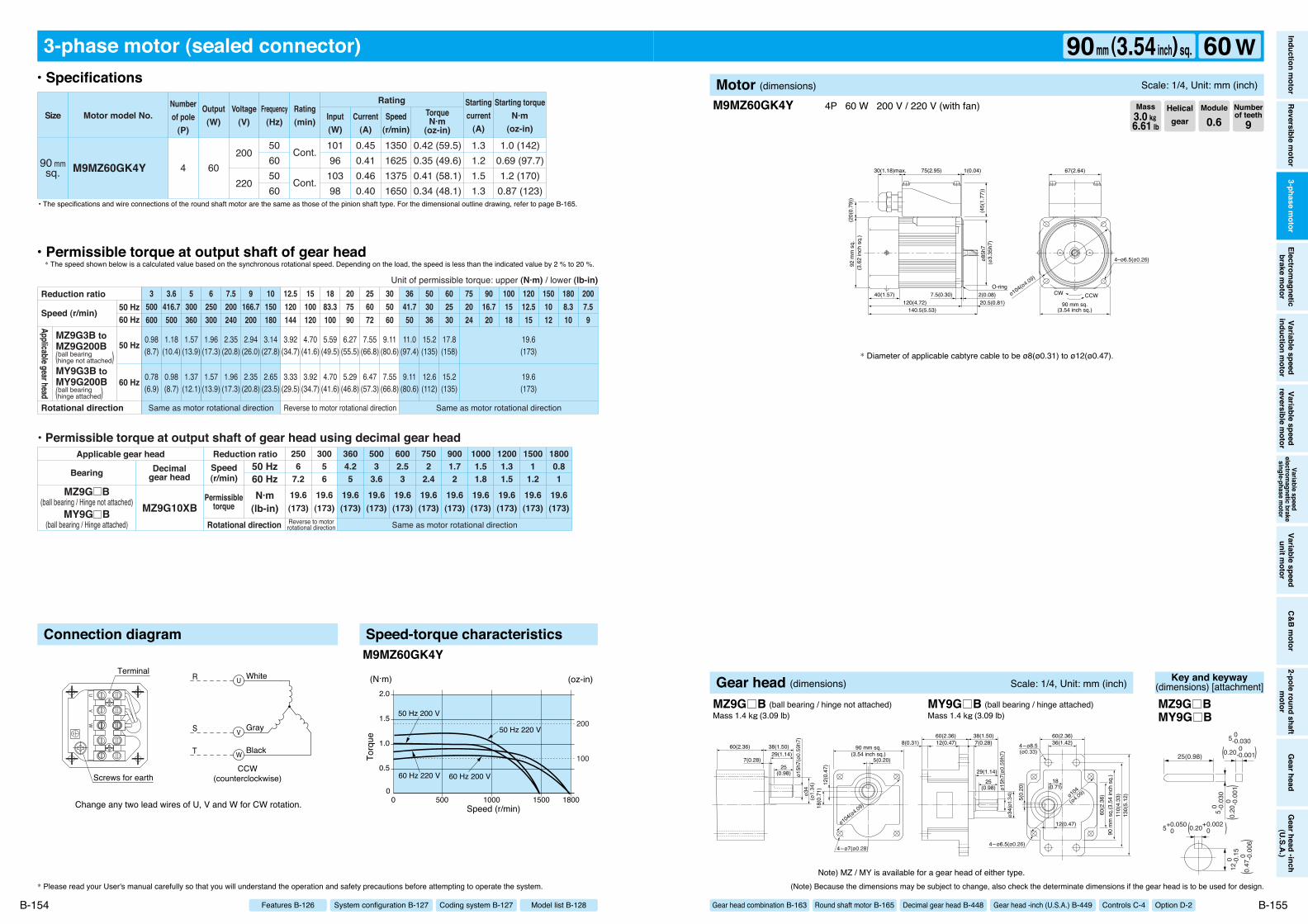
75(2.95) 1(0.04)30(1.18)max.
CCWCW
67(2.64)
140.5(5.53)120(4.72) 20.5(0.81)
7.5(0.30)40(1.57) 2(0.08)
ø85h
7
92 m
m s
q.
(45(
1.77
))
(20(
0.79
))
4–ø6.5(ø0.26)
90 mm sq.(3.54 inch sq.)
O-ring
(3.6
2 in
ch s
q.)
ø104(ø4.09)
(ø3.
35h7
)
Change any two lead wires of U, V and W for CW rotation.
R
S
T
White
Gray
Black
CCW(counterclockwise)
UV
W
Terminal
Screws for earth
W
V
U
3-phase motor (sealed connector)
90 mmsq. M9MZ60GK4Y
1.0 (142)0.69 (97.7)1.2 (170)0.87 (123)
0.42 (59.5)0.35 (49.6)0.41 (58.1)0.34 (48.1)
4 60200
220
50605060
10196
10398
0.450.410.460.40
1350162513751650
1.31.21.51.3
Cont.
Cont.
Motor model No.Rating
SizeNumberof pole
(P)
Output(W)
Voltage(V)
Frequency(Hz)
Rating(min) Input
(W)Current
(A)
TorqueN·m
(oz-in)
Starting torqueN·m
(oz-in)
Startingcurrent
(A)Speed
(r/min)
Same as motor rotational direction
19.6(173)
19.6(173)
19.6(173)
19.6(173)
19.6(173)
19.6(173)
19.6(173)
19.6(173)
19.6(173)
19.6(173)
19.6(173)
6002.53
5003
3.6
2506
7.2
30056
3604.25
7502
2.4
9001.72
10001.51.8
12001.31.5
15001
1.2
18000.81
0.98(8.7)
1.18(10.4)
1.57(13.9)
1.96(17.3)
2.35(20.8)
2.94(26.0)
3.14(27.8)
3.92(34.7)
4.70(41.6)
5.59(49.5)
6.27(55.5)
7.55(66.8)
9.11(80.6)
11.0(97.4)
15.2(135)
17.8(158)
19.6(173)
0.78(6.9)
0.98(8.7)
1.37(12.1)
1.57(13.9)
1.96(17.3)
2.35(20.8)
2.65(23.5)
3.33(29.5)
3.92(34.7)
4.70(41.6)
5.29(46.8)
6.47(57.3)
7.55(66.8)
9.11(80.6)
12.6(112)
15.2(135)
19.6(173)
3500600
3.6416.7500
5300360
6250300
7.5200240
9166.7200
10150180
12.5120144
15100120
1883.3100
207590
256072
305060
3641.750
503036
602530
752024
9016.720
1001518
12012.515
1808.310
2007.59
1501012
Same as motor rotational direction Same as motor rotational directionReverse to motor rotational direction
Reverse to motorrotational direction
• Permissible torque at output shaft of gear head using decimal gear head
MZ9G10XBMZ9G B
(ball bearing / Hinge not attached)MY9G B
(ball bearing / Hinge attached)
Applicable gear head
Bearing Decimalgear head
Speed(r/min)
Permissibletorque
50 Hz60 HzN·m
(lb-in)Rotational direction
Reduction ratio
Reduction ratio
Rotational direction
Speed (r/min)
Unit of permissible torque: upper (N·m) / lower (lb-in)
MZ9G3B toMZ9G200B
MY9G3B toMY9G200B
Applicable gear head
ball bearing(hinge not attached)
ball bearing(hinge attached)
50 Hz60 Hz
50 Hz
60 Hz
Connection diagram Speed-torque characteristics
00 1800
2.0
1.5
1.0
0.5
15001000500
50 Hz 200 V
50 Hz 220 V
60 Hz 200 V60 Hz 220 V
(N·m)
Speed (r/min)
Torq
ue
(oz-in)
100
200
M9MZ60GK4Y
M9MZ60GK4Y 4P 60 W 200 V / 220 V (with fan)
* Please read your User's manual carefully so that you will understand the operation and safety precautions before attempting to operate the system. (Note) Because the dimensions may be subject to change, also check the determinate dimensions if the gear head is to be used for design.
B-154 B-155
• Specifications
• Permissible torque at output shaft of gear head* The speed shown below is a calculated value based on the synchronous rotational speed. Depending on the load, the speed is less than the indicated value by 2 % to 20 %.
• The specifications and wire connections of the round shaft motor are the same as those of the pinion shaft type. For the dimensional outline drawing, refer to page B-165.
* Diameter of applicable cabtyre cable to be ø8(ø0.31) to ø12(ø0.47).
Helicalgear
Module
0.6Numberof teeth
9Mass3.0 k""6.61 lb
Model list B-128Coding system B-127System configuration B-127Features B-126
Inductionm
otorReversible
motor
3-phasem
otorElectrom
agneticbrake
motor
Variablespeed
inductionm
otorVariable
speedreversible
motor
Variablespeed
electromagnetic
brakesingle-phase
motor
Variablespeed
unitmotor
C&Bm
otor2-pole
roundshaft
motor
Gearhead
Gearhead
-inch(U.S.A.)
90mm (3.54inch) sq. 60 WMotor (dimensions) Scale: 1/4, Unit: mm (inch)
Gear head combination B-163 Round shaft motor B-165 Decimal gear head B-448 Gear head -inch (U.S.A.) B-449 Controls C-4 Option D-2
Note) MZ / MY is available for a gear head of either type.
ø15h
7(ø0
.59h
7)ø3
4(ø
1.34
) 12(0
.47)
18(0
.71)
5(0.20)
90 mm sq.(3.54 inch sq.)
ø104(ø4.09)
4–ø7(ø0.28)
29(1.14)
25(0.98)
7(0.28)
60(2.36) 38(1.50)
5(0.
20)
ø34(
ø1.3
4)ø1
5h7(
ø0.5
9h7)
110(
4.33
)13
0(5.
12)
60(2.36)36(1.42)4–ø8.5
(ø0.33)
4–ø6.5(ø0.26)
60(2.36) 38(1.50)7(0.28)
29(1.14)
12(0.47)8(0.31)
25(0.98)
18(0.71)
12(0.47)
ø104
(ø4.09)
90 m
m s
q.(3
.54
inch
sq.
)60
(2.3
6)
Gear head (dimensions) Scale: 1/4, Unit: mm (inch)
MZ9G B (ball bearing / hinge not attached) MY9G B (ball bearing / hinge attached)Mass 1.4 k"(3.09 lb) Mass 1.4 k"(3.09 lb)
Key and keyway(dimensions) [attachment]
25(0.98)
5 0 -0.
030
12 0
-0
.15
5 0 -0.030
0.20 0 -0.001
5+0.050 0
( )
0.20
0
-0
.001
(
)
0.20+0.002 0( )
0.47
0
-0
.006
(
)
MZ9G BMY9G B
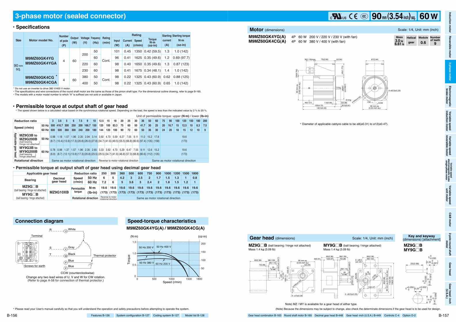
75(2.95) 1(0.04)30(1.18)max.
CCWCW
67(2.64)
140.5(5.53)120(4.72) 20.5(0.81)
7.5(0.30)40(1.57) 2(0.08)
ø85h
7
92 m
m s
q.
(45(
1.77
))
(20(
0.79
))
4–ø6.5(ø0.26)
90 mm sq.(3.54 inch sq.)
O-ring
(3.6
2 in
ch s
q.)
ø104(ø4.09)
(ø3.
35h7
)
M9MZ60GK4YG(A)M9MZ60GK4CG(A)
4P 60 W 200 V / 220 V / 230 V (with fan) 4P 60 W 380 V / 400 V (with fan)
* Diameter of applicable cabtyre cable to be ø8(ø0.31) to ø12(ø0.47).
(Note) Because the dimensions may be subject to change, also check the determinate dimensions if the gear head is to be used for design.
B-157
Helicalgear
Module
0.6Numberof teeth
9Mass3.0 k""6.61 lb
Inductionm
otorReversible
motor
3-phasem
otorElectrom
agneticbrake
motor
Variablespeed
inductionm
otorVariable
speedreversible
motor
Variablespeed
electromagnetic
brakesingle-phase
motor
Variablespeed
unitmotor
C&Bm
otor2-pole
roundshaft
motor
Gearhead
Gearhead
-inch(U.S.A.)
90mm (3.54inch) sq. 60 WMotor (dimensions) Scale: 1/4, Unit: mm (inch)
Gear head combination B-163 Round shaft motor B-165 Decimal gear head B-448 Gear head -inch (U.S.A.) B-449 Controls C-4 Option D-2
(Refer to page A-58 for connection of thermal protector.)
PP
UV
W
Change any two lead wires of U, V and W for CW rotation.CCW (counterclockwise)
R
S
T
White
Gray
Black Thermal protectorBlue
Blue
Terminal
Screws for earth
W
V
U
P
P
3-phase motor (sealed connector)
M9MZ60GK4YGM9MZ60GK4YGA
M9MZ60GK4CG *M9MZ60GK4CGA
1.0 (142)
0.69 (97.7)
0.87 (123)
1.0 (142)
0.88 (125)
1.0 (142)
0.42 (59.5)
0.35 (49.6)
0.35 (49.6)
0.34 (48.1)
0.43 (60.9)
0.43 (60.9)
90 mmsq.
4
4
60
60
50
60
60
60
50
50
200
220
230
380
400
101
96
98
98
98
98
0.45
0.41
0.40
0.41
0.22
0.22
1350
1625
1650
1675
1325
1325
1.3
1.2
1.3
1.4
0.62
0.65
Cont.
Cont.
Motor model No.Rating
SizeNumberof pole
(P)
Output(W)
Voltage(V)
Frequency(Hz)
Rating(min) Input
(W)Current
(A)
TorqueN·m
(oz-in)
Starting torqueN·m
(oz-in)
Startingcurrent
(A)Speed
(r/min)
19.6(173)
19.6(173)
19.6(173)
19.6(173)
19.6(173)
19.6(173)
19.6(173)
19.6(173)
19.6(173)
19.6(173)
19.6(173)
6002.53
5003
3.6
2506
7.2
30056
3604.25
7502
2.4
9001.72
10001.51.8
12001.31.5
15001
1.2
18000.81
0.98(8.7)
1.18(10.4)
1.57(13.9)
1.96(17.3)
2.35(20.8)
2.94(26.0)
3.14(27.8)
3.92(34.7)
4.70(41.6)
5.59(49.5)
6.27(55.5)
7.55(66.8)
9.11(80.6)
11.0(97.4)
15.2(135)
17.8(158)
19.6(173)
0.78(6.9)
0.98(8.7)
1.37(12.1)
1.57(13.9)
1.96(17.3)
2.35(20.8)
2.65(23.5)
3.33(29.5)
3.92(34.7)
4.70(41.6)
5.29(46.8)
6.47(57.3)
7.55(66.8)
9.11(80.6)
12.6(112)
15.2(135)
19.6(173)
3500600
3.6416.7500
5300360
6250300
7.5200240
9166.7200
10150180
12.5120144
15100120
1883.3100
207590
256072
305060
3641.750
503036
602530
752024
9016.720
1001518
12012.515
1808.310
2007.59
1501012
Same as motor rotational directionReverse to motorrotational direction
• Permissible torque at output shaft of gear head using decimal gear head
MZ9G10XBMZ9G B
(ball bearing / hinge not attached)MY9G B
(ball bearing / hinge attached)
Applicable gear head
Bearing Decimalgear head
Speed(r/min)
Permissibletorque
50 Hz60 HzN·m
(lb-in)Rotational direction
Reduction ratio
Same as motor rotational direction Same as motor rotational directionReverse to motor rotational direction
Reduction ratio
Rotational direction
Speed (r/min)
Unit of permissible torque: upper (N·m) / lower (lb-in)
MZ9G3B toMZ9G200B
MY9G3B toMY9G200B
Applicable gear head
ball bearing(hinge not attached)
ball bearing(hinge attached)
50 Hz60 Hz
50 Hz
60 Hz
Connection diagram Speed-torque characteristics
00 1800
1.5
1.0
0.5
15001000500
(N·m)
Speed (r/min)
Torq
ue
150
100
50
200
(oz-in)
60 Hz 200 V
50 Hz 200 V 50 Hz 400 V
50 Hz 380 V
M9MZ60GK4YG(A) / M9MZ60GK4CG(A)
* Please read your User's manual carefully so that you will understand the operation and safety precautions before attempting to operate the system.
B-156
• Specifications
• Permissible torque at output shaft of gear head* The speed shown below is a calculated value based on the synchronous rotational speed. Depending on the load, the speed is less than the indicated value by 2 % to 20 %.
* Do not use an inverter to drive 380 V/400 V motor.• The specifications and wire connections of the round shaft motor are the same as those of the pinion shaft type. For the dimensional outline drawing, refer to page B-165.• The models with a motor model number to which “A” is suffixed are not sold or available in Japan.
Model list B-128Coding system B-127System configuration B-127Features B-126
Note) MZ / MY is available for a gear head of either type.
ø15h
7(ø0
.59h
7)ø3
4(ø
1.34
) 12(0
.47)
18(0
.71)
5(0.20)
90 mm sq.(3.54 inch sq.)
ø104(ø4.09)
4–ø7(ø0.28)
29(1.14)
25(0.98)
7(0.28)
60(2.36) 38(1.50)
5(0.
20)
ø34(
ø1.3
4)ø1
5h7(
ø0.5
9h7)
110(
4.33
)13
0(5.
12)
60(2.36)36(1.42)4–ø8.5
(ø0.33)
4–ø6.5(ø0.26)
60(2.36) 38(1.50)7(0.28)
29(1.14)
12(0.47)8(0.31)
25(0.98)
18(0.71)
12(0.47)
ø104
(ø4.09)
90 m
m s
q.(3
.54
inch
sq.
)60
(2.3
6)
Gear head (dimensions) Scale: 1/4, Unit: mm (inch)
MZ9G B (ball bearing / hinge not attached) MY9G B (ball bearing / hinge attached)Mass 1.4 k"(3.09 lb) Mass 1.4 k"(3.09 lb)
Key and keyway(dimensions) [attachment]
25(0.98)
5 0 -0.
030
12 0
-0
.15
5 0 -0.030
0.20 0 -0.001
5+0.050 0
( )
0.20
0
-0
.001
(
)
0.20+0.002 0( )
0.47
0
-0
.006
(
)
MZ9G BMY9G B

90 mm sq.(3.54 inch sq.)
75(2.95) 1(0.04)30(1.18)max.
4–ø6.5(ø0.26)
CCWCW
67(2.64)
155.5(6.12)135(5.31) 20.5(0.81)
7.5(0.30)40(1.57) 2(0.08)
ø85h
7
92 m
m s
q.
O-ring
(45(
1.77
))
(20(
0.79
))(3
.62
inch
sq.
)
ø104(ø4.09)
(ø3.
35h7
)
Change any two lead wires of U, V and W for CW rotation.
R
S
T
White
Gray
Black
CCW(counterclockwise)
UV
W
Terminal
Screws for earth
W
V
U
3-phase motor (sealed connector)
90 mmsq. M9MZ90GK4Y
1.6 (227)1.1 (156)2.0 (283)1.4 (198)
0.63 (89.2)0.53 (75.1)0.62 (87.8)0.52 (73.6)
4 90200
220
50605060
141137143137
0.620.560.650.56
1350162514001650
2.01.82.22.0
Cont.
Cont.
Motor model No.Rating
SizeNumberof pole
(P)
Output(W)
Voltage(V)
Frequency(Hz)
Rating(min) Input
(W)Current
(A)
TorqueN·m
(oz-in)
Starting torqueN·m
(oz-in)
Startingcurrent
(A)Speed
(r/min)
19.6(173)
19.6(173)
19.6(173)
19.6(173)
19.6(173)
19.6(173)
19.6(173)
19.6(173)
19.6(173)
19.6(173)
19.6(173)
6002.53
5003
3.6
2506
7.2
30056
3604.25
7502
2.4
9001.72
10001.51.8
12001.31.5
15001
1.2
18000.81
1.18(10.4)
1.37(12.1)
1.86(16.5)
2.25(19.9)
2.84(25.1)
3.43(30.4)
3.72(32.9)
4.70(41.6)
5.68(50.3)
6.76(59.8)
7.55(66.8)
9.21(81.5)
10.9(96.5)
13.0(115)
18.3(162)
19.6(173)
1.37(12.1)
1.67(14.8)
2.25(19.9)
2.74(24.3)
3.43(30.4)
4.12(36.5)
4.51(39.9)
5.68(50.3)
6.76(59.8)
8.04(71.2)
9.02(79.8)
10.9(96.5)
13.0(115)
15.7(139)
19.6(173)
19.6(173)
3500600
3.6416.7500
5300360
6250300
7.5200240
9166.7200
10150180
12.5120144
15100120
1883.3100
207590
256072
305060
3641.750
503036
602530
752024
9016.720
1001518
12012.515
1808.310
2007.59
1501012
Same as motor rotational directionReverse to motorrotational direction
• Permissible torque at output shaft of gear head using decimal gear head
MZ9G10XBMZ9G B
(ball bearing / hinge not attached)MY9G B
(ball bearing / hinge attached)
Applicable gear head
Bearing Decimalgear head
Speed(r/min)
Permissibletorque
50 Hz60 HzN·m
(lb-in)Rotational direction
Reduction ratio
Same as motor rotational direction Same as motor rotational directionReverse to motor rotational direction
Reduction ratio
Rotational direction
Speed (r/min)
Unit of permissible torque: upper (N·m) / lower (lb-in)
MZ9G3B toMZ9G200B
MY9G3B toMY9G200B
Applicable gear head
ball bearing(hinge not attached)
ball bearing(hinge attached)
50 Hz60 Hz
50 Hz
60 Hz
Connection diagram Speed-torque characteristics
0
0.5
2.0
2.5
1.5
1.0
0 180015001000500
50 Hz 200 V
50 Hz 220 V
60 Hz 200 V60 Hz 220 V
(N·m)
Speed (r/min)
Torq
ue
(oz-in)
200
100
300
M9MZ90GK4Y
M9MZ90GK4Y 4P 90 W 200 V / 220 V (with fan)
* Please read your User's manual carefully so that you will understand the operation and safety precautions before attempting to operate the system. (Note) Because the dimensions may be subject to change, also check the determinate dimensions if the gear head is to be used for design.
B-158 B-159
• Specifications
• Permissible torque at output shaft of gear head* The speed shown below is a calculated value based on the synchronous rotational speed. Depending on the load, the speed is less than the indicated value by 2 % to 20 %.
• The specifications and wire connections of the round shaft motor are the same as those of the pinion shaft type. For the dimensional outline drawing, refer to page B-165.
* Diameter of applicable cabtyre cable to be ø8(ø0.31) to ø12(ø0.47).
Helicalgear
Module
0.6Numberof teeth
9Mass3.3 k""7.28 lb
Model list B-128Coding system B-127System configuration B-127Features B-126
Inductionm
otorReversible
motor
3-phasem
otorElectrom
agneticbrake
motor
Variablespeed
inductionm
otorVariable
speedreversible
motor
Variablespeed
electromagnetic
brakesingle-phase
motor
Variablespeed
unitmotor
C&Bm
otor2-pole
roundshaft
motor
Gearhead
Gearhead
-inch(U.S.A.)
90mm (3.54inch) sq. 90 WMotor (dimensions) Scale: 1/4, Unit: mm (inch)
Gear head combination B-163 Round shaft motor B-165 Decimal gear head B-448 Gear head -inch (U.S.A.) B-449 Controls C-4 Option D-2
Note) MZ / MY is available for a gear head of either type.
ø15h
7(ø0
.59h
7)ø3
4(ø
1.34
) 12(0
.47)
18(0
.71)
5(0.20)
90 mm sq.(3.54 inch sq.)
ø104(ø4.09)
4–ø7(ø0.28)
29(1.14)
25(0.98)
7(0.28)
60(2.36) 38(1.50)
5(0.
20)
ø34(
ø1.3
4)ø1
5h7(
ø0.5
9h7)
110(
4.33
)13
0(5.
12)
60(2.36)36(1.42)4–ø8.5
(ø0.33)
4–ø6.5(ø0.26)
60(2.36) 38(1.50)7(0.28)
29(1.14)
12(0.47)8(0.31)
25(0.98)
18(0.71)
12(0.47)
ø104
(ø4.09)
90 m
m s
q.(3
.54
inch
sq.
)60
(2.3
6)
Gear head (dimensions) Scale: 1/4, Unit: mm (inch)
MZ9G B (ball bearing / hinge not attached) MY9G B (ball bearing / hinge attached)Mass 1.4 k"(3.09 lb) Mass 1.4 k"(3.09 lb)
Key and keyway(dimensions) [attachment]
25(0.98)
5 0 -0.
030
12 0
-0
.15
5 0 -0.030
0.20 0 -0.001
5+0.050 0
( )
0.20
0
-0
.001
(
)
0.20+0.002 0( )
0.47
0
-0
.006
(
)
MZ9G BMY9G B
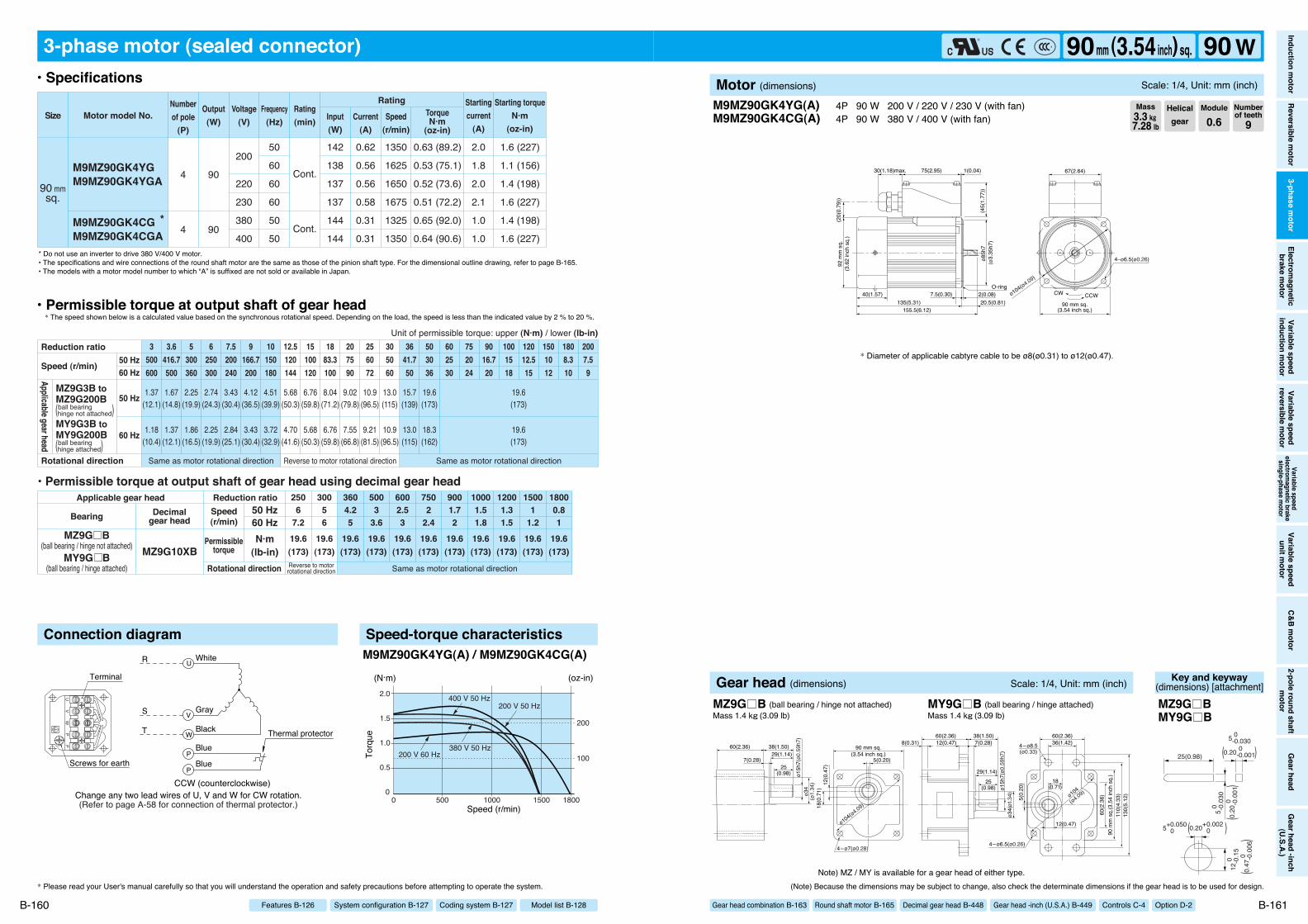
90 mm sq.(3.54 inch sq.)
75(2.95) 1(0.04)30(1.18)max.
4–ø6.5(ø0.26)
CCWCW
67(2.64)
155.5(6.12)135(5.31) 20.5(0.81)
7.5(0.30)40(1.57) 2(0.08)
ø85h
7
92 m
m s
q.
O-ring
(45(
1.77
))
(20(
0.79
))(3
.62
inch
sq.
)
ø104(ø4.09)
(ø3.
35h7
)
(Refer to page A-58 for connection of thermal protector.)
PP
UV
W
Change any two lead wires of U, V and W for CW rotation.CCW (counterclockwise)
R
S
T
White
Gray
Black Thermal protectorBlue
Blue
Terminal
Screws for earth
W
V
U
P
P
3-phase motor (sealed connector)
M9MZ90GK4YGM9MZ90GK4YGA
M9MZ90GK4CG *M9MZ90GK4CGA
1.6 (227)
1.1 (156)
1.4 (198)
1.6 (227)
1.4 (198)
1.6 (227)
0.63 (89.2)
0.53 (75.1)
0.52 (73.6)
0.51 (72.2)
0.65 (92.0)
0.64 (90.6)
90 mmsq.
4
4
90
90
50
60
60
60
50
50
200
220
230
380
400
142
138
137
137
144
144
0.62
0.56
0.56
0.58
0.31
0.31
1350
1625
1650
1675
1325
1350
2.0
1.8
2.0
2.1
1.0
1.0
Cont.
Cont.
Motor model No.Rating
SizeNumberof pole
(P)
Output(W)
Voltage(V)
Frequency(Hz)
Rating(min) Input
(W)Current
(A)
TorqueN·m
(oz-in)
Starting torqueN·m
(oz-in)
Startingcurrent
(A)Speed
(r/min)
19.6(173)
19.6(173)
19.6(173)
19.6(173)
19.6(173)
19.6(173)
19.6(173)
19.6(173)
19.6(173)
19.6(173)
19.6(173)
6002.53
5003
3.6
2506
7.2
30056
3604.25
7502
2.4
9001.72
10001.51.8
12001.31.5
15001
1.2
18000.81
1.18(10.4)
1.37(12.1)
1.86(16.5)
2.25(19.9)
2.84(25.1)
3.43(30.4)
3.72(32.9)
4.70(41.6)
5.68(50.3)
6.76(59.8)
7.55(66.8)
9.21(81.5)
10.9(96.5)
13.0(115)
18.3(162)
19.6(173)
1.37(12.1)
1.67(14.8)
2.25(19.9)
2.74(24.3)
3.43(30.4)
4.12(36.5)
4.51(39.9)
5.68(50.3)
6.76(59.8)
8.04(71.2)
9.02(79.8)
10.9(96.5)
13.0(115)
15.7(139)
19.6(173)
19.6(173)
3500600
3.6416.7500
5300360
6250300
7.5200240
9166.7200
10150180
12.5120144
15100120
1883.3100
207590
256072
305060
3641.750
503036
602530
752024
9016.720
1001518
12012.515
1808.310
2007.59
1501012
Same as motor rotational directionReverse to motorrotational direction
• Permissible torque at output shaft of gear head using decimal gear head
MZ9G10XBMZ9G B
(ball bearing / hinge not attached)MY9G B
(ball bearing / hinge attached)
Applicable gear head
Bearing Decimalgear head
Speed(r/min)
Permissibletorque
50 Hz60 HzN·m
(lb-in)Rotational direction
Reduction ratio
Same as motor rotational direction Same as motor rotational directionReverse to motor rotational direction
50 Hz60 Hz
50 Hz
60 Hz
Reduction ratio
Rotational direction
Speed (r/min)
Unit of permissible torque: upper (N·m) / lower (lb-in)
MZ9G3B toMZ9G200B
MY9G3B toMY9G200B
Applicable gear head
ball bearing(hinge not attached)
ball bearing(hinge attached)
Connection diagram Speed-torque characteristics
00 1800
2.0
1.5
1.0
0.5
15001000500
(N·m)
Speed (r/min)
Torq
ue
(oz-in)
100
200
200 V 60 Hz380 V 50 Hz
200 V 50 Hz400 V 50 Hz
M9MZ90GK4YG(A) / M9MZ90GK4CG(A)
M9MZ90GK4YG(A)M9MZ90GK4CG(A)
4P 90 W 200 V / 220 V / 230 V (with fan) 4P 90 W 380 V / 400 V (with fan)
* Diameter of applicable cabtyre cable to be ø8(ø0.31) to ø12(ø0.47).
* Please read your User's manual carefully so that you will understand the operation and safety precautions before attempting to operate the system. (Note) Because the dimensions may be subject to change, also check the determinate dimensions if the gear head is to be used for design.
B-160 B-161
• Specifications
• Permissible torque at output shaft of gear head* The speed shown below is a calculated value based on the synchronous rotational speed. Depending on the load, the speed is less than the indicated value by 2 % to 20 %.
* Do not use an inverter to drive 380 V/400 V motor.• The specifications and wire connections of the round shaft motor are the same as those of the pinion shaft type. For the dimensional outline drawing, refer to page B-165.• The models with a motor model number to which “A” is suffixed are not sold or available in Japan.
Helicalgear
Module
0.6Numberof teeth
9Mass3.3 k""7.28 lb
Model list B-128Coding system B-127System configuration B-127Features B-126
Inductionm
otorReversible
motor
3-phasem
otorElectrom
agneticbrake
motor
Variablespeed
inductionm
otorVariable
speedreversible
motor
Variablespeed
electromagnetic
brakesingle-phase
motor
Variablespeed
unitmotor
C&Bm
otor2-pole
roundshaft
motor
Gearhead
Gearhead
-inch(U.S.A.)
90mm (3.54inch) sq. 90 WMotor (dimensions) Scale: 1/4, Unit: mm (inch)
Gear head combination B-163 Round shaft motor B-165 Decimal gear head B-448 Gear head -inch (U.S.A.) B-449 Controls C-4 Option D-2
Note) MZ / MY is available for a gear head of either type.
ø15h
7(ø0
.59h
7)ø3
4(ø
1.34
) 12(0
.47)
18(0
.71)
5(0.20)
90 mm sq.(3.54 inch sq.)
ø104(ø4.09)
4–ø7(ø0.28)
29(1.14)
25(0.98)
7(0.28)
60(2.36) 38(1.50)
5(0.
20)
ø34(
ø1.3
4)ø1
5h7(
ø0.5
9h7)
110(
4.33
)13
0(5.
12)
60(2.36)36(1.42)4–ø8.5
(ø0.33)
4–ø6.5(ø0.26)
60(2.36) 38(1.50)7(0.28)
29(1.14)
12(0.47)8(0.31)
25(0.98)
18(0.71)
12(0.47)
ø104
(ø4.09)
90 m
m s
q.(3
.54
inch
sq.
)60
(2.3
6)
Gear head (dimensions) Scale: 1/4, Unit: mm (inch)
MZ9G B (ball bearing / hinge not attached) MY9G B (ball bearing / hinge attached)Mass 1.4 k"(3.09 lb) Mass 1.4 k"(3.09 lb)
Key and keyway(dimensions) [attachment]
25(0.98)
5 0 -0.
030
12 0
-0
.15
5 0 -0.030
0.20 0 -0.001
5+0.050 0
( )
0.20
0
-0
.001
(
)
0.20+0.002 0( )
0.47
0
-0
.006
(
)
MZ9G BMY9G B

Specifications B-130 to B-161 Option D-2Controls C-4
Inductionm
otorReversible
motor
3-phasem
otorElectrom
agneticbrake
motor
Variablespeed
inductionm
otorVariable
speedreversible
motor
Variablespeed
electromagnetic
brakesingle-phase
motor
Variablespeed
unitmotor
C&Bm
otor2-pole
roundshaft
motor
Gearhead
Gearhead
-inch(U.S.A.)
3-phase motor (sealed connector)
(Note) Because the dimensions may be subject to change, also check the determinate dimensions if the gear head is to be used for design.
B-163
3-phase motor (leadwire)
* Please read your User's manual carefully so that you will understand the operation and safety precautions before attempting to operate the system.
B-162 Model list B-128Coding system B-127System configuration B-127Features B-126
+ MX8G B(M)+ MX8G B(M)
M8MX25G4YM8MX25G4YG(A)
115(4.53)85(3.35)
7(0.28)
ø10h
7(ø
0.39
h7)
ø30
(ø1.
18)
30(1.18)32(1.26)
25(0.98)6
(0.24)
Motor leadwires300±30 mm (11.8±1.18 inch)
AWG20
MAX
ø86(
ø3.3
9)
+ MX9G B(M)+ MX9G B(M)
M9MX40G4YM9MX40G4YG(A)
142(5.59)105(4.13)
7.5(0.30)
Motor leadwires300±30 mm (11.8±1.18 inch)
AWG20
MAX
ø95(
ø3.7
4)
ø12h
7(ø0
.47)
ø36
(ø1.
42)
37(1.46)32(1.26)
25(0.98)5(0.20)
+ MZ9G B (MY9G B)+ MZ9G B (MY9G B)
M9MZ60G4YM9MZ60G4YG(A)
180(7.09)120(4.72)
7.5(0.30)40(1.57)
Motor leadwires300±30 mm (11.8±1.18 inch)
AWG20
92 m
m s
q.(3
.62
inch
sq.
)
ø15h
7(ø0
.59h
7)ø3
4(ø
1.34
)
29(1.14)
25(0.98)
7(0.28)
60(2.36)38(1.50)
+ MY9G B (MZ9G B)+ MY9G B (MZ9G B)
M9MZ90G4YM9MZ90G4YG(A)
195(7.68)135(5.31)
7.5(0.30)40(1.57)
92 m
m s
q.(3
.62
inch
sq.
)
Motor leadwires300±30 mm (11.8±1.18 inch)
AWG20
ø34
(ø1.
34)
ø15h
7(ø0
.59h
7)
60(2.36)38(1.50)
7(0.28)
29(1.14)
12(0.47)8(0.31)
25(0.98)
+ MX8G B(M)+ MX8G B(M)+ MX8G B(M)
M8MX25GK4YM8MX25GK4YG(A)M8MX25GK4CG(A)
96.3(3.79)85(3.35)
75(2.95) 1(0.04)30(1.18)max.
7(0.28)
MAX
ø86(
ø3.3
9)(2
0(0.
79))
(45(
1.77
))
ø10h
7(ø
0.39
h7)
ø30
(ø1.
18)
30(1.18)32(1.26)
25(0.98)
6(0.24)
+ MX9G B(M)+ MX9G B(M)+ MX9G B(M)
M9MX40GK4YM9MX40GK4YG(A)M9MX40GK4CG(A)
(45(
1.77
))
142(5.59)105(4.13)
7.5(0.30)
75(2.95) 1(0.04)30(1.18)max.
MAX
ø95(
ø3.7
4)(2
0(0.
79))
ø12h
7(ø0
.47)
ø36
(ø1.
42)
37(1.46)32(1.26)
25(0.98)
5(0.20)
+ MZ9G B (MY9G B)+ MZ9G B (MY9G B)+ MZ9G B (MY9G B)
M9MZ60GK4YM9MZ60GK4YG(A)M9MZ60GK4CG(A)
75(2.95) 1(0.04)30(1.18)max.
180(7.09)120(4.72)
7.5(0.30)40(1.57)
92 m
m s
q.(3
.62
inch
sq.
)
(45(
1.77
))
(20(
0.79
))
ø15h
7(ø0
.59h
7)ø3
4(ø
1.34
)
29(1.14)
25(0.98)7(0.28)
60(2.36)38(1.50)
* Diameter of applicable cabtyre cable to be ø8(ø0.31) to ø12(ø0.47).* Refer to page B-444 for high torque gear head.
* Refer to page B-444 for high torque gear head. * Refer to page B-444 for high torque gear head.
* Diameter of applicable cabtyre cable to be ø8(ø0.31) to ø12(ø0.47). * Diameter of applicable cabtyre cable to be ø8(ø0.31) to ø12(ø0.47).
+ MY9G B (MZ9G B)+ MY9G B (MZ9G B)+ MY9G B (MZ9G B)
M9MZ90GK4YM9MZ90GK4YG(A)M9MZ90GK4CG(A)
75(2.95) 1(0.04)30(1.18)max.
195(7.68)135(5.31)
40(1.57)
92 m
m s
q.(3
.62
inch
sq.
)
(45(
1.77
))
(20(
0.79
))
ø34
(ø1.3
4)
ø15h
7(ø0
.59h
7)
60(2.36)38(1.50)
7(0.28)
29(1.14)
12(0.47)8(0.31)
25(0.98)
7.5(0.30)
* Diameter of applicable cabtyre cable to be ø8(ø0.31) to ø12(ø0.47).* Refer to page B-444 for high torque gear head.
Gear head combination dimensionsScale: 1/4, Unit: mm (inch)
Gear head combination dimensionsScale: 1/4, Unit: mm (inch)
*The models with a motor model number to which “A” is suffixed are not sold or available in Japan.
80 mm sq. (3.15 inch sq.) 25 W
90 mm sq. (3.54 inch sq.) 60 W
90 mm sq. (3.54 inch sq.) 40 W
90 mm sq. (3.54 inch sq.) 90 W
80 mm sq. (3.15 inch sq.) 25 W
90 mm sq. (3.54 inch sq.) 60 W
90 mm sq. (3.54 inch sq.) 40 W
90 mm sq. (3.54 inch sq.) 90 W
* Gear head is sold separately. * Gear head is sold separately.

Specifications B-130 to B-161 Option D-2Controls C-4
Inductionm
otorReversible
motor
3-phasem
otorElectrom
agneticbrake
motor
Variablespeed
inductionm
otorVariable
speedreversible
motor
Variablespeed
electromagnetic
brakesingle-phase
motor
Variablespeed
unitmotor
C&Bm
otor2-pole
roundshaft
motor
Gearhead
Gearhead
-inch(U.S.A.)
(Note) Because the dimensions may be subject to change, also check the determinate dimensions if the gear head is to be used for design.
B-165
3-phase motor (4-pole round shaft / leadwire)
* Please read your User's manual carefully so that you will understand the operation and safety precautions before attempting to operate the system.
B-164 Model list B-128Coding system B-127System configuration B-127Features B-126
M8MX25S4YSM8MX25S4YG(A)
Motor leadwires300±30 mm (11.8±1.18 inch)
AWG20
ø73h
7(ø
2.87
h7)
MAX
ø86(
ø3.3
9)
85(3.35) 32(1.26)7(0.28) 3(0.12)
80 mm sq.(3.15 inch sq.)
CWCCW25
(0.98)ø8
h7(ø
0.31
h7)
7(0.
28)
ø94(ø3.70)
4–ø5.5(ø0.22)
M9MX40S4YSM9MX40S4YG(A)
105(4.13) 37(1.46)7.5(0.30) 3(0.12)
ø83h
7(ø
3.27
h7)
90 mm sq.(3.54 inch sq.)
CWCCW
Motor leadwires300±30 mm (11.8±1.18 inch)
AWG20
30(1.18)
ø10h
7(ø
0.39
h7)
9(0.
35)
MAX
ø95(
ø3.7
4)
4–ø6.5(ø0.26)ø104(ø4.09)
M9MZ60S4YS (with fan)M9MZ60S4YG(A) (with fan)
120(4.72) 37(1.46)7.5(0.30)40(1.57) 3(0.12)
ø83h
7(ø
3.27
h7)
90 mm sq.(3.54 inch sq.)
CWCCW
Motor leadwires300±30 mm (11.8±1.18 inch)
AWG20
92 m
m s
q.(3
.62
inch
sq.
)
30(1.18)
ø12h
7(ø
0.47
h7)
11(0
.43)
4–ø6.5(ø0.26)ø104(ø4.09)
M9MZ90S4YS (with fan)M9MZ90S4YG(A) (with fan)
4–ø6.5(ø0.26)
CWCCW
92 m
m s
q.(3
.62
inch
sq.
)
Motor leadwires300±30 mm (11.8±1.18 inch)
AWG20
90 mm sq.(3.54 inch sq.)
135(5.31) 37(1.46)7.5(0.30)40(1.57) 3(0.12)
ø83h
7(ø
3.27
h7)
30(1.18)
ø12h
7(ø
0.47
h7)
11(0
.43)
ø104(ø4.09)
M9MZ60SK4YS (with fan)M9MZ60SK4YG(A) (with fan)M9MZ60SK4CG(A) (with fan)
75(2.95) 1(0.04)30(1.18)max.
CCWCW
67(2.64)
120(4.72) 37(1.46)7.5(0.30)40(1.57) 3(0.12)
ø83h
7(ø
3.27
h7)
92 m
m s
q.(3
.62
inch
sq.
)
30(1.18)
ø12h
7(ø
0.47
h7)
11(0
.43)
(45(
1.77
))
(20(
0.79
))
4–ø6.5(ø0.26)
90 mm sq.(3.54 inch sq.)
ø104(ø4.09)
M9MZ90SK4YS (with fan)M9MZ90SK4YG(A) (with fan)M9MZ90SK4CG(A) (with fan)
90 mm sq.(3.54 inch sq.)
ø104
(ø4.09)
75(2.95) 1(0.04)30(1.18)max.
CCWCW
67(2.64)
135(5.31) 37(1.46)7.5(0.30)40(1.57) 3(0.12)
ø83h
7(ø
3.27
h7)
92 m
m s
q.(3
.62
inch
sq.
)
30(1.18)
ø12h
7(ø
0.47
h7)
11(0
.43)
(45(
1.77
))
(20(
0.79
))
4–ø6.5(ø0.26)
M8MX25SK4YS M8MX25SK4YG(A)M8MX25SK4CG(A)
85(3.35)
75(2.95) 1(0.04)30(1.18)max.
32(1.26)7(0.28) 3(0.12)
ø73h
7(ø
2.87
h7)
4–ø5.5(ø0.22)
CCWCW
67(2.64)
25(0.98)
øø8h
7(ø
0.31
h7)
7(0.
28)
MAX
ø86(
ø3.3
9)
(45(
1.77
))
(20(
0.79
))
80 mm sq.(3.15 inch sq.)
ø94(ø3.70)
M9MX40SK4YS M9MX40SK4YG(A)M9MX40SK4CG(A)
ø83h
7(ø
3.27
h7)
105(4.13) 37(1.46)7.5(0.30) 3(0.12)
75(2.95) 1(0.04)30(1.18)max.
CCWCW
67(2.64)
30(1.18)
ø10h
7(ø
0.39
h7)
9(0.
35)
(45(
1.77
))
(20(
0.79
))M
AXø9
5(ø3
.74)
4–ø6.5(ø0.26)
90 mm sq.(3.54 inch sq.)
ø104(ø4.09)
3-phase motor (4-pole round shaft / sealed connector) DimensionsScale: 1/4, Unit: mm (inch)
DimensionsScale: 1/4, Unit: mm (inch)
* Diameter of applicable cabtyre cable to be ø8(ø0.31) to ø12(ø0.47). * Diameter of applicable cabtyre cable to be ø8(ø0.31) to ø12(ø0.47).
* Diameter of applicable cabtyre cable to be ø8(ø0.31) to ø12(ø0.47). * Diameter of applicable cabtyre cable to be ø8(ø0.31) to ø12(ø0.47).
200 V/220 V/230 V round shaft motors with a sealed connector (with a terminal box) are covered by the Electrical Appliance and Material Safety Law. The indications on their nameplate are based on this law.
*The models with a motor model number to which “A” is suffixed are not sold or available in Japan.
Mass1.5 k"(3.31 lb)80 mm sq. (3.15 inch sq.) 25 W Mass
2.4 k"(5.29 lb)90 mm sq. (3.54 inch sq.) 40 W
Mass2.7 k"(5.95 lb)90 mm sq. (3.54 inch sq.) 60 W Mass
3.2 k"(7.05 lb)90 mm sq. (3.54 inch sq.) 90 W
Mass1.8 k"(3.97 lb)80 mm sq. (3.15 inch sq.) 25 W Mass
2.8 k"(6.17 lb)90 mm sq. (3.54 inch sq.) 40 W
Mass3.0 k"(6.61 lb)90 mm sq. (3.54 inch sq.) 60 W Mass
3.3 k"(7.28 lb)90 mm sq. (3.54 inch sq.) 90 W
* Please refer to the pinion shaft motor for wiring and specifications of the motor.* Please refer to the pinion shaft motor for wiring and specifications of the motor.

3-phase Motor
• Motor Overview• Model list• Product information for each model• Gear head combination dimensions• Round shaft motor dimensions
ContentsB-126B-128B-130B-162B-164
* Please read your User's manual carefully so that you will understand the operation and safety precautions before attempting to operate the system.
B-124
Reversible motor (4-pole round shaft / leadwire)
Reversible motor (4-pole round shaft /sealed connector)
DimensionsScale: 1/4, Unit: mm (inch)
M9RZ60S4LS (with fan)M9RZ60S4YS (with fan)
M9RZ60S4LG(A) (with fan)M9RZ60S4DG(A) (with fan)M9RZ60S4YG(A) (with fan)M9RZ60S4GG(A) (with fan)
120(4.72) 37(1.46)7.5(0.30)40(1.57) 3(0.12)
ø83h
7(ø
3.27
h7)
90 mm sq.(3.54 inch sq.)
CWCCW
Motor leadwires300±30 mm (11.8±1.18 inch)
AWG20
92 m
m s
q.(3
.62
inch
sq.
)
30(1.18)
ø12h
7(ø
0.47
h7)
11(0
.43)
4–ø6.5(ø0.26)ø104(ø4.09)
M9RZ90S4LS (with fan)M9RZ90S4YS (with fan)
M9RZ90S4LG(A) (with fan)M9RZ90S4DG(A) (with fan)M9RZ90S4YG(A) (with fan)M9RZ90S4GG(A) (with fan)
4–ø6.5(ø0.26)
CWCCW
92 m
m s
q.(3
.62
inch
sq.
)
Motor leadwires300±30 mm (11.8±1.18 inch)
AWG20
90 mm sq.(3.54 inch sq.)
135(5.31) 37(1.46)7.5(0.30)40(1.57) 3(0.12)
ø83h
7(ø
3.27
h7)
30(1.18)
ø12h
7(ø
0.47
h7)
11(0
.43)
ø104(ø4.09)
M9RZ60SK4LS (with fan)M9RZ60SK4YS (with fan)
M9RZ60SK4LG(A) (with fan)M9RZ60SK4DG(A) (with fan)M9RZ60SK4YG(A) (with fan)M9RZ60SK4GG(A) (with fan)
75(2.95) 1(0.04)30(1.18)max.
CCWCW
67(2.64)
120(4.72) 37(1.46)7.5(0.30)40(1.57) 3(0.12)
ø83h
7(ø
3.27
h7)
92 m
m s
q.(3
.62
inch
sq.
)
30(1.18)
ø12h
7(ø
0.47
h7)
11(0
.43)
(45(
1.77
))
(20(
0.79
))
4–ø6.5(ø0.26)
90 mm sq.(3.54 inch sq.)
ø104(ø4.09)
M9RZ90SK4LS (with fan)M9RZ90SK4YS (with fan)
M9RZ90SK4LG(A) (with fan)M9RZ90SK4DG(A) (with fan)M9RZ90SK4YG(A) (with fan)M9RZ90SK4GG(A) (with fan)
90 mm sq.(3.54 inch sq.)
ø104
(ø4.09)
75(2.95) 1(0.04)30(1.18)max.
CCWCW
67(2.64)
135(5.31) 37(1.46)7.5(0.30)40(1.57) 3(0.12)
ø83h
7(ø
3.27
h7)
92 m
m s
q.(3
.62
inch
sq.
)
30(1.18)
ø12h
7(ø
0.47
h7)
11(0
.43)
(45(
1.77
))
(20(
0.79
))
4–ø6.5(ø0.26)
DimensionsScale: 1/4, Unit: mm (inch)
M8RX25SK4LS M8RX25SK4LG(A)M8RX25SK4YS M8RX25SK4YG(A)
M8RX25SK4DG(A)M8RX25SK4GG(A)
85(3.35)
75(2.95) 1(0.04)30(1.18)max.
32(1.26)7(0.28) 3(0.12)
ø73h
7(ø
2.87
h7)
4–ø5.5(ø0.22)
CCWCW
67(2.64)
25(0.98)
øø8h
7(ø
0.31
h7)
7(0.
28)
MAX
ø86(
ø3.3
9)
(45(
1.77
))
(20(
0.79
))
80 mm sq.(3.15 inch sq.)
ø94(ø3.70)
M9RX40SK4LS M9RX40SK4LG(A)M9RX40SK4YS M9RX40SK4YG(A)
M9RX40SK4DG(A)M9RX40SK4GG(A)
ø83h
7(ø
3.27
h7)
105(4.13) 37(1.46)7.5(0.30) 3(0.12)
75(2.95) 1(0.04)30(1.18)max.
CCWCW
67(2.64)
30(1.18)
ø10h
7(ø
0.39
h7)
9(0.
35)
(45(
1.77
))
(20(
0.79
))M
AXø9
5(ø3
.74)
4–ø6.5(ø0.26)
90 mm sq.(3.54 inch sq.)
ø104(ø4.09)
100 V/200 V round shaft motors with a sealed connector (with a terminal box) are covered by the ElectricalAppliance and Material Safety Law. The indications on their nameplate are based on this law.
*The models with a motor model number to which “A” is suffixed are not equipped with a capacitor cap.*The models with a motor model number to which “A” is suffixed are not sold or available in Japan.
Mass2.7 k(5.95 lb)90 mm sq. (3.54 inch sq.) 60 W Mass
3.2 k(7.05 lb)90 mm sq. (3.54 inch sq.) 90 W
Mass1.8 k(3.97 lb)80 mm sq. (3.15 inch sq.) 25 W Mass
2.8 k(6.17 lb)90 mm sq. (3.54 inch sq.) 40 W
Mass3.0 k(6.61 lb)90 mm sq. (3.54 inch sq.) 60 W Mass
3.3 k(7.28 lb)90 mm sq. (3.54 inch sq.) 90 W
* Please refer to the pinion shaft motor for wiring and specifications of the motor.

B-126
Outline of 3-phase motor
Features• The 3-phase motor is an induction motor for 3-phase power.• Continuous time rating• The motor with national specifications is of heatproof class 120 (E); the motor with specifications compliant with
overseas standards is of heatproof class 130 (B).
Note) 3-phase motor start-stop operation must not exceed 6-cycles per minute or damage may occur.
Construction
Characteristics• Speed-torque characteristics
StatorArmature
Shaft WindingFrameBracketBall bearingOil sealWave washer
Ball bearing
Example:M8MX25G4Y
Speed (r/min)0
1.0
0.8
0.6
0.4
0.2
1800
Torq
ue (N
·m)
15001000500
50 Hz 220 V50 Hz 200 V
60 Hz 220 V60 Hz 200 V
System configuration diagram
Coding system
Brake unit (sold separately)Used when stopping the motor instantaneously C-31
Motor
ACpower supply
<3-phase>
Mounting frame (option) D-2
M 9 M X 40 G 4 Y G A
8 : 80 mm sq. (3.15 inch sq.)9 : 90 mm sq. (3.54 inch sq.)
G: Pinion shaftS : Round shaft
X : 40 W or smallerZ : 60 W or larger
K : Sealed connector
Y : National specifications: 3-phase 200 V/220 V Specifications compliant with overseas standards: 3-phase 200 V/220 V/230 V
C : 3-phase 380 V/400 V
M : 3-phase motor 25 : 25 W40 : 40 W60 : 60 W90 : 90 W
4 : 4 poles
Size Motortype
Outputtype
Output Shapeof shaft
Option No. ofpoles
Voltage Classification 1 Classification 2
G: Specifications compliant with overseas standards
S : Round shaft (S for round shaft with national specifications only)
Left aligned when(no option is used )
Correspondingmodel number
Shape ofshaft Classification
Specifications compliantwith overseas standardsPinion shaftSpecifications compliant withoverseas standardsRound shaftNational specificationsPinion shaftNational specificationsRound shaft42 mm sq. round shaftspecifications
G
S
G
S
S
G
G
–
S
–
The models with a motor modelnumber to which “A” is suffixedare not sold or available in Japan.
Fit tolerance symbol is used in the outside dimension diagram of motor and gear head. For further information, see “Fit tolerance” on page A-33.
Fit tolerance
Gear head (sold separately)(Mounting screws for gear head: Attachment)
Decimal gear head (sold separately)Used when a high reduction ratio is needed
( ) B-448
Mounting screws for decimal gear head: Sold separately
B-127

B-128 B-129
Model list of 3-phase motor
80 mm sq.(3.15 inch sq.)
90 mm sq.(3.54 inch sq.)
25
40
60
90
*Refer to page B-444 for dimensions and permissible torque of high torque gear head.Refer to page B-446 for dimensions and permissible torque of right-angle gear head.Refer to page B-451 for dimensions and permissible torque of gear head -Inch (U.S.A.).Refer to page B-448 for dimensions of decimal gear head.
M8MX25G4YM8MX25G4YG(A)
M9MX40G4YM9MX40G4YG(A)
M9MZ60G4YM9MZ60G4YG(A)
M9MZ90G4YM9MZ90G4YG(A)
200 V/220 V200 V/220 V/230 V
200 V/220 V200 V/220 V/230 V
200 V/220 V200 V/220 V/230 V
200 V/220 V200 V/220 V/230 V
B-130B-132
B-134B-136
B-138B-140
B-142B-144
M8MX25GK4YM8MX25GK4YG(A)M8MX25GK4CG(A)M9MX40GK4YM9MX40GK4YG(A)M9MX40GK4CG(A)M9MZ60GK4YM9MZ60GK4YG(A)M9MZ60GK4CG(A)M9MZ90GK4YM9MZ90GK4YG(A)M9MZ90GK4CG(A)
B-146B-148B-148B-150B-152B-152B-154B-156B-156B-158B-160B-160
MX8G B
MX9G B
MZ9G B
MY9G B
MX8G M
MX9G M
–
–
–
MR9G B
MP9G B
–
MX9G R
MZ9G
R
MX8G10XB
MX9G10XB
MZ9G10XB
80 mm sq.(3.15 inch sq.)
90 mm sq.(3.54 inch sq.)
25
40
60
90
M8MX25S4YSM8MX25S4YG(A)
M9MX40S4YSM9MX40S4YG(A)
M9MZ60S4YSM9MZ60S4YG(A)
M9MZ90S4YSM9MZ90S4YG(A)
200 V/220 V200 V/220 V/230 V
200 V/220 V200 V/220 V/230 V
200 V/220 V200 V/220 V/230 V
200 V/220 V200 V/220 V/230 V
M8MX25SK4YSM8MX25SK4YG(A)M8MX25SK4CG(A)M9MX40SK4YSM9MX40SK4YG(A)M9MX40SK4CG(A)M9MZ60SK4YSM9MZ60SK4YG(A)M9MZ60SK4CG(A)M9MZ90SK4YSM9MZ90SK4YG(A)M9MZ90SK4CG(A)
200 V/220 V200 V/220 V/230 V380 V/400 V200 V/220 V200 V/220 V/230 V380 V/400 V200 V/220 V200 V/220 V/230 V380 V/400 V200 V/220 V200 V/220 V/230 V380 V/400 V
200 V/220 V200 V/220 V/230 V380 V/400 V200 V/220 V200 V/220 V/230 V380 V/400 V200 V/220 V200 V/220 V/230 V380 V/400 V200 V/220 V200 V/220 V/230 V380 V/400 V
Output(W)
SizeLeadwire typeModel number Specifications Page
Sealed connector typeModel number Specifications Page
Hinge attachedStandard gear head
Ball bearing metal bearingDecimal
gear headHigh torquegear head
Right-anglegear head
MX9G BU
MX9G BU
MZ9G
BU
Gear head -Inch(U.S.A.)
Output(W)
SizeLeadwire typeModel number
Sealed connector typeModel number
Electrical Appliance and Material Safety Law
Specifications Specifications
* The specifications and wire connections of the round shaft motor are the same as those of the pinion shaft motor. Dimensional outline drawing Page B-164.
<Notice>380 V/400 V 3-phase round shaft motors with a sealed connector are not covered by the Electrical Appliance and Material Safety Law.
Motor compliant with overseas standards Motor compliant with China efficiency standards
Motor compliant with overseas standards Motor compliant with China efficiency standards
Applicable gear headPinion shaft motor
Round shaft motor

96.3(3.79)85(3.35) 11.3(0.44)
7(0.28) 2(0.08)
ø75h
7
80 mm sq.
4–ø5.5(ø0.22)
CWCCW
3 motor leadwires 300±30 mm (11.8±1.18 inch)AWG20
O-ring
ø94(ø3.70)
MAX
ø86(
ø3.3
9)
(3.15 inch sq.)
(ø2.
95h7
)
Change any two lead wires of R, S and T for CW rotation.
R
S
T
White
Gray
Black
CCW(counterclockwise)
3-phase motor (leadwire)
80 mmsq. M8MX25G4Y
0.54 (76.5)0.40 (56.6)0.66 (93.5)0.50 (70.8)
0.18 (25.5)0.15 (21.2)0.18 (25.5)0.15 (21.2)
4 25200
220
50605060
50475449
0.250.220.270.23
1350162513751650
0.620.580.670.64
Cont.
Cont.
Motor model No.Rating
SizeNumberof pole
(P)
Output(W)
Voltage(V)
Frequency(Hz)
Rating(min) Input
(W)Current
(A)
TorqueN·m
(oz-in)
Starting torqueN·m
(oz-in)
Startingcurrent
(A)Speed
(r/min)
7.84(69.4)
7.84(69.4)
7.84(69.4)
7.84(69.4)
7.84(69.4)
7.84(69.4)
7.84(69.4)
7.84(69.4)
7.84(69.4)
7.84(69.4)
7.84(69.4)
7.84(69.4)
6002.53
5003
3.6
2506
7.2
30056
3604.25
2007.59
7502
2.4
9001.72
10001.51.8
12001.31.5
15001
1.2
18000.81
0.39(3.45)
0.47(4.16)
0.66(5.84)
0.78(6.90)
0.98(8.67)
1.18(10.4)
1.27(11.2)
1.57(13.9)
1.96(17.3)
2.35(20.8)
2.55(22.6)
3.14(27.8)
3.82(33.8)
4.61(40.8)
6.37(56.4)
7.64(67.6)
7.84(69.4)
0.32(2.83)
0.39(3.45)
0.55(4.87)
0.66(5.84)
0.81(7.17)
0.98(8.67)
1.08(9.56)
1.27(11.2)
1.57(13.9)
1.96(17.3)
2.06(18.2)
2.65(23.5)
3.14(27.8)
3.82(33.8)
5.29(46.8)
6.37(56.4)
7.84(69.4)
3500600
3.6416.7500
5300360
6250300
7.5200240
9166.7200
10150180
12.5120144
15100120
1883.3100
207590
256072
305060
3641.750
503036
602530
752024
9016.720
1001518
12012.515
1501012
1808.310
• Permissible torque at output shaft of gear head using decimal gear head
MX8G10XBSame as motor
rotational direction Reverse to motor rotational direction
MX8G B(ball bearing)MX8G M
(metal bearing)
Same as motor rotational direction Reverse to motor rotational direction
Applicable gear head
Bearing Decimalgear head
Speed(r/min)
Permissibletorque
50 Hz60 HzN·m
(lb-in)Rotational direction
Reduction ratio
Reduction ratio
Rotational direction
Speed (r/min)
Unit of permissible torque: upper (N·m) / lower (lb-in)!
MX8G3B toMX8G180B(ball bearing)MX8G3M toMX8G180M(metal bearing)
Applicable gear head
50 Hz60 Hz
50 Hz
60 Hz
Connection diagram Speed-torque characteristics
00 1800
1.0
0.8
0.6
0.4
0.2
15001000500
60 Hz 200 V60 Hz 220 V
50 Hz 200 V50 Hz 220 V
(N·m)
Speed (r/min)
Torq
ue
(oz-in)
100
50
M8MX25G4Y
M8MX25G4Y 4P 25 W 200 V / 220 V
* Please read your User's manual carefully so that you will understand the operation and safety precautions before attempting to operate the system. (Note) Because the dimensions may be subject to change, also check the determinate dimensions if the gear head is to be used for design.
B-130 B-131
• Specifications
• Permissible torque at output shaft of gear head* The speed shown below is a calculated value based on the synchronous rotational speed. Depending on the load, the speed is less than the indicated value by 2 % to 20 %.
• The specifications and wire connections of the round shaft motor are the same as those of the pinion shaft type. For the dimensional outline drawing, refer to page B-164.
Helicalgear
Module
0.5Numberof teeth
9Mass1.5 k""3.31 lb
Model list B-128Coding system B-127System configuration B-127Features B-126
Inductionm
otorReversible
motor
3-phasem
otorElectrom
agneticbrake
motor
Variablespeed
inductionm
otorVariable
speedreversible
motor
Variablespeed
electromagnetic
brakesingle-phase
motor
Variablespeed
unitmotor
C&Bm
otor2-pole
roundshaft
motor
Gearhead
Gearhead
-inch(U.S.A.)
80mm (3.15inch) sq. 25 WMotor (dimensions) Scale: 1/3, Unit: mm (inch)
Gear head combination B-162 Round shaft motor B-164 Decimal gear head B-448 Gear head -inch (U.S.A.) B-449 Controls C-4 Option D-2ø1
0h7
ø30
(ø1.
18)
(ø0.
39h7
)
7.5(
0.30
)15
(0.5
9)
4(0.16)
80 mm sq.(3.15 inch sq.)
ø94(ø3.70)
4–ø5.5(ø0.22)
30(1.18) 32(1.26)25
(0.98)6(0.24)
Gear head (dimensions) Scale: 1/3, Unit: mm (inch)
MX8G B (ball bearing) Mass 0.6 k"(1.32 lb) MX8G M (metal bearing) Mass 0.6 k"(1.32 lb)
Key and keyway(dimensions) [attachment]
25(0.98)
4 0 -0.
030
7.5 0
-
0.15
4 0 -0.030
0.16 0 -0.001
4+0.060 +0.010
( )
0.16
0
-0
.001
(
)
0.16+0.002 +0.0004( )
0.3 0
-
0.00
6(
)
MX8G B(M)

(Refer to page A-58 for connection of thermal protector.)
CCW(counterclockwise)
R
S
T
White
Gray
Black
Blue
Blue Thermal protector
Change any two lead wires of R, S and T for CW rotation.
3-phase motor (leadwire)
80 mmsq.
M8MX25G4YGM8MX25G4YGA
0.54 (76.5)0.40 (56.6)0.50 (70.8)0.54 (76.5)
0.18 (25.5)0.15 (21.2)0.14 (19.8)0.14 (19.8)
4 25
50606060
200
220230
50474950
0.250.220.230.24
1350162516501675
0.620.580.640.65
Cont.
Motor model No.Rating
SizeNumberof pole
(P)
Output(W)
Voltage(V)
Frequency(Hz)
Rating(min) Input
(W)Current
(A)
TorqueN·m
(oz-in)
Starting torqueN·m
(oz-in)
Startingcurrent
(A)Speed
(r/min)
7.84(69.4)
7.84(69.4)
7.84(69.4)
7.84(69.4)
7.84(69.4)
7.84(69.4)
7.84(69.4)
7.84(69.4)
7.84(69.4)
7.84(69.4)
7.84(69.4)
7.84(69.4)
6002.53
5003
3.6
2506
7.2
30056
3604.25
2007.59
7502
2.4
9001.72
10001.51.8
12001.31.5
15001
1.2
18000.81
0.39(3.45)
0.47(4.16)
0.66(5.84)
0.78(6.90)
0.98(8.67)
1.18(10.4)
1.27(11.2)
1.57(13.9)
1.96(17.3)
2.35(20.8)
2.55(22.6)
3.14(27.8)
3.82(33.8)
4.61(40.8)
6.37(56.4)
7.64(67.6)
7.84(69.4)
0.32(2.83)
0.39(3.45)
0.55(4.87)
0.66(5.84)
0.81(7.17)
0.98(8.67)
1.08(9.56)
1.27(11.2)
1.57(13.9)
1.96(17.3)
2.06(18.2)
2.65(23.5)
3.14(27.8)
3.82(33.8)
5.29(46.8)
6.37(56.4)
7.84(69.4)
3500600
3.6416.7500
5300360
6250300
7.5200240
9166.7200
10150180
12.5120144
15100120
1883.3100
207590
256072
305060
3641.750
503036
602530
752024
9016.720
1001518
12012.515
1501012
1808.310
• Permissible torque at output shaft of gear head using decimal gear head
MX8G10XBSame as motor
rotational direction Reverse to motor rotational direction
MX8G B(ball bearing)MX8G M
(metal bearing)
Same as motor rotational direction Reverse to motor rotational direction
Applicable gear head
Bearing Decimalgear head
Speed(r/min)
Permissibletorque
50 Hz60 HzN·m
(lb-in)Rotational direction
Reduction ratio
Reduction ratio
Rotational direction
Speed (r/min)
Unit of permissible torque: upper (N·m) / lower (lb-in)!
MX8G3B toMX8G180B(ball bearing)MX8G3M toMX8G180M(metal bearing)
Applicable gear head
50 Hz60 Hz
50 Hz
60 Hz
Connection diagram Speed-torque characteristics
00 1800
1.0
0.8
0.6
0.4
0.2
15001000500
(N·m)
Speed (r/min)
Torq
ue
(oz-in)
100
5060 Hz 200 V
50 Hz 200 V
M8MX25G4YG(A)
* Please read your User's manual carefully so that you will understand the operation and safety precautions before attempting to operate the system.
B-132
• Specifications
• Permissible torque at output shaft of gear head* The speed shown below is a calculated value based on the synchronous rotational speed. Depending on the load, the speed is less than the indicated value by 2 % to 20 %.
• The specifications and wire connections of the round shaft motor are the same as those of the pinion shaft type. For the dimensional outline drawing, refer to page B-164.
Model list B-128Coding system B-127System configuration B-127Features B-126
• The models with a motor model number to which “A” is suffixed are not sold or available in Japan.
96.3(3.79)85(3.35) 11.3(0.44)
7(0.28) 2(0.08)
ø75h
7
80 mm sq.
4–ø5.5(ø0.22)
CWCCW
5 motor leadwires 300±30 mm (11.8±1.18 inch)AWG20
O-ring
ø94(ø3.70)
MAX
ø86(
ø3.3
9)
(3.15 inch sq.)
(ø2.
95h7
)
M8MX25G4YG(A) 4P 25 W 200 V / 220 V / 230 V
(Note) Because the dimensions may be subject to change, also check the determinate dimensions if the gear head is to be used for design.
B-133
Helicalgear
Module
0.5Numberof teeth
9Mass1.5 k""3.31 lb
Inductionm
otorReversible
motor
3-phasem
otorElectrom
agneticbrake
motor
Variablespeed
inductionm
otorVariable
speedreversible
motor
Variablespeed
electromagnetic
brakesingle-phase
motor
Variablespeed
unitmotor
C&Bm
otor2-pole
roundshaft
motor
Gearhead
Gearhead
-inch(U.S.A.)
80mm (3.15inch) sq. 25 WMotor (dimensions) Scale: 1/3, Unit: mm (inch)
Gear head combination B-162 Round shaft motor B-164 Decimal gear head B-448 Gear head -inch (U.S.A.) B-449 Controls C-4 Option D-2ø1
0h7
ø30
(ø1.
18)
(ø0.
39h7
)
7.5(
0.30
)15
(0.5
9)
4(0.16)
80 mm sq.(3.15 inch sq.)
ø94(ø3.70)
4–ø5.5(ø0.22)
30(1.18) 32(1.26)25
(0.98)6(0.24)
Gear head (dimensions) Scale: 1/3, Unit: mm (inch)
MX8G B (ball bearing) Mass 0.6 k"(1.32 lb) MX8G M (metal bearing) Mass 0.6 k"(1.32 lb)
Key and keyway(dimensions) [attachment]
25(0.98)
4 0 -0.
030
7.5 0
-
0.15
4 0 -0.030
0.16 0 -0.001
4+0.060 +0.010
( )
0.16
0
-0
.001
(
)
0.16+0.002 +0.0004( )
0.3 0
-
0.00
6(
)
MX8G B(M)

117.8(4.64)105(4.13) 12.8(0.50)
7.5(0.30) 2(0.08)
ø85h
7
90 mm sq.
4–ø6.5(ø0.26)
CWCCW
3 motor leadwires 300±30 mm (11.8±1.18 inch)AWG20
ø104(ø4.09)
MAX
ø95(
ø3.7
4)
O-ring
(3.54 inch sq.)
(ø3.
35h7
)
Change any two lead wires of R, S and T for CW rotation.
R
S
T
White
Gray
Black
CCW(counterclockwise)
3-phase motor (leadwire)
90 mmsq. M9MX40G4Y
0.72 (102)0.51 (72.2)0.88 (125)0.63 (89.2)
0.28 (39.7)0.24 (34.0)0.27 (38.2)0.23 (32.6)
4 40200
220
50605060
69687066
0.310.290.320.28
1350162513751675
0.900.821.00.91
Cont.
Cont.
Motor model No.Rating
SizeNumberof pole
(P)
Output(W)
Voltage(V)
Frequency(Hz)
Rating(min) Input
(W)Current
(A)
TorqueN·m
(oz-in)
Starting torqueN·m
(oz-in)
Startingcurrent
(A)Speed
(r/min)
9.80(86.7)
9.80(86.7)
9.80(86.7)
9.80(86.7)
9.80(86.7)
9.80(86.7)
9.80(86.7)
9.80(86.7)
9.80(86.7)
9.80(86.7)
9.80(86.7)
9.80(86.7)
6002.53
5003
3.6
2506
7.2
30056
3604.25
2007.59
7502
2.4
9001.72
10001.51.8
12001.31.5
15001
1.2
18000.81
0.66(5.84)
0.78(6.90)
1.08(9.56)
1.27(11.2)
1.57(13.9)
1.86(16.5)
2.25(19.9)
2.74(24.3)
3.23(28.6)
3.92(34.7)
4.41(39.0)
5.29(46.8)
6.37(56.4)
7.94(70.3)
9.80(86.7)
9.80(86.7)
0.55(4.87)
0.66(5.84)
0.90(7.97)
1.08(9.56)
1.27(11.2)
1.57(13.9)
1.76(15.6)
2.25(19.9)
2.74(24.3)
3.23(28.6)
3.53(31.2)
4.41(39.0)
5.29(46.8)
6.37(56.4)
8.82(78.1)
9.80(86.7)
3500600
3.6416.7500
5300360
6250300
7.5200240
9166.7200
10150180
12.5120144
15100120
1883.3100
207590
256072
305060
3641.750
503036
602530
752024
9016.720
1001518
12012.515
1501012
1808.310
• Permissible torque at output shaft of gear head using decimal gear head
MX9G10XBSame as motor
rotational direction Reverse to motor rotational direction
MX9G B(ball bearing)MX9G M
(metal bearing)
Same as motor rotational direction Reverse to motor rotational direction
Applicable gear head
Bearing Decimalgear head
Speed(r/min)
Permissibletorque
50 Hz60 HzN·m
(lb-in)Rotational direction
Reduction ratio
Reduction ratio
Rotational direction
Speed (r/min)
Unit of permissible torque: upper (N·m) / lower (lb-in)
MX9G3B toMX9G180B(ball bearing)MX9G3M toMX9G180M(metal bearing)
Applicable gear head
50 Hz60 Hz
50 Hz
60 Hz
Connection diagram Speed-torque characteristics
00 1800
1.0
0.8
0.6
0.4
0.2
15001000500
60 Hz 200 V60 Hz 220 V
50 Hz 200 V50 Hz 220 V
(N·m)
Speed (r/min)
Torq
ue
(oz-in)
100
50
M9MX40G4Y
M9MX40G4Y 4P 40 W 200 V / 220 V
* Please read your User's manual carefully so that you will understand the operation and safety precautions before attempting to operate the system. (Note) Because the dimensions may be subject to change, also check the determinate dimensions if the gear head is to be used for design.
B-134 B-135
• Specifications
• Permissible torque at output shaft of gear head* The speed shown below is a calculated value based on the synchronous rotational speed. Depending on the load, the speed is less than the indicated value by 2 % to 20 %.
• The specifications and wire connections of the round shaft motor are the same as those of the pinion shaft type. For the dimensional outline drawing, refer to page B-164.
Helicalgear
Module
0.55Numberof teeth
9Mass2.4 k""5.29 lb
Model list B-128Coding system B-127System configuration B-127Features B-126
Inductionm
otorReversible
motor
3-phasem
otorElectrom
agneticbrake
motor
Variablespeed
inductionm
otorVariable
speedreversible
motor
Variablespeed
electromagnetic
brakesingle-phase
motor
Variablespeed
unitmotor
C&Bm
otor2-pole
roundshaft
motor
Gearhead
Gearhead
-inch(U.S.A.)
90mm (3.54inch) sq. 40 WMotor (dimensions) Scale: 1/3, Unit: mm (inch)
Gear head combination B-162 Round shaft motor B-164 Decimal gear head B-448 Gear head -inch (U.S.A.) B-449 Controls C-4 Option D-2
ø12h
7(ø0
.47)
ø36
(ø1.
42) 9.
5(0.
37)
18(0
.71)
4(0.16)
90 mm sq.(3.54 inch sq.)
ø104(ø4.09)
4–ø7(ø0.28)
37(1.46) 32(1.26)
25(0.98)
5(0.20)
Gear head (dimensions) Scale: 1/3, Unit: mm (inch)
MX9G B (ball bearing) Mass 0.8 k"(1.76 lb) MX9G M (metal bearing) Mass 0.8 k"(1.76 lb)
Key and keyway(dimensions) [attachment]
25(0.98)
4 0 -0.
030
9.5 0
-
0.15
4 0 -0.030
0.16 0 -0.001
4+0.060 +0.010
( )
0.16
0
-0
.001
(
)
0.16+0.002 +0.0004( )
0.37
0
-0
.006
(
)
MX9G B(M)

(Refer to page A-58 for connection of thermal protector.)
CCW(counterclockwise)
R
S
T
White
Gray
Black
Blue
Blue Thermal protector
Change any two lead wires of R, S and T for CW rotation.
3-phase motor (leadwire)
90 mmsq.
M9MX40G4YGM9MX40G4YGA
0.72 (102)0.51 (72.2)0.63 (89.2)0.69 (97.7)
0.28 (39.7)0.24 (34.0)0.23 (32.6)0.23 (32.6)
4 40
50606060
200
220230
69686666
0.310.290.280.29
1350162516751675
0.900.820.910.96
Cont.
Motor model No.Rating
SizeNumberof pole
(P)
Output(W)
Voltage(V)
Frequency(Hz)
Rating(min) Input
(W)Current
(A)
TorqueN·m
(oz-in)
Starting torqueN·m
(oz-in)
Startingcurrent
(A)Speed
(r/min)
9.80(86.7)
9.80(86.7)
9.80(86.7)
9.80(86.7)
9.80(86.7)
9.80(86.7)
9.80(86.7)
9.80(86.7)
9.80(86.7)
9.80(86.7)
9.80(86.7)
9.80(86.7)
6002.53
5003
3.6
2506
7.2
30056
3604.25
2007.59
7502
2.4
9001.72
10001.51.8
12001.31.5
15001
1.2
18000.81
0.66(5.84)
0.78(6.90)
1.08(9.56)
1.27(11.2)
1.57(13.9)
1.86(16.5)
2.25(19.9)
2.74(24.3)
3.23(28.6)
3.92(34.7)
4.41(39.0)
5.29(46.8)
6.37(56.4)
7.94(70.3)
9.80(86.7)
9.80(86.7)
0.55(4.87)
0.66(5.84)
0.90(7.97)
1.08(9.56)
1.27(11.2)
1.57(13.9)
1.76(15.6)
2.25(19.9)
2.74(24.3)
3.23(28.6)
3.53(31.2)
4.41(39.0)
5.29(46.8)
6.37(56.4)
8.82(78.1)
9.80(86.7)
3500600
3.6416.7500
5300360
6250300
7.5200240
9166.7200
10150180
12.5120144
15100120
1883.3100
207590
256072
305060
3641.750
503036
602530
752024
9016.720
1001518
12012.515
1501012
1808.310
• Permissible torque at output shaft of gear head using decimal gear head
MX9G10XBSame as motor
rotational direction Reverse to motor rotational direction
MX9G B(ball bearing)MX9G M
(metal bearing)
Same as motor rotational direction Reverse to motor rotational direction
Applicable gear head
Bearing Decimalgear head
Speed(r/min)
Permissibletorque
50 Hz60 HzN·m
(lb-in)Rotational direction
Reduction ratio
Reduction ratio
Rotational direction
Speed (r/min)
Unit of permissible torque: upper (N·m) / lower (lb-in)
MX9G3B toMX9G180B(ball bearing)MX9G3M toMX9G180M(metal bearing)
Applicable gear head
50 Hz60 Hz
50 Hz
60 Hz
Connection diagram Speed-torque characteristics
00 1800
1.0
0.8
0.6
0.4
0.2
15001000500
(N·m)
Speed (r/min)
Torq
ue
(oz-in)
100
50200 V 60 Hz
200 V 50 Hz
M9MX40G4YG(A)
* Please read your User's manual carefully so that you will understand the operation and safety precautions before attempting to operate the system.
B-136
• Specifications
• Permissible torque at output shaft of gear head* The speed shown below is a calculated value based on the synchronous rotational speed. Depending on the load, the speed is less than the indicated value by 2 % to 20 %.
• The specifications and wire connections of the round shaft motor are the same as those of the pinion shaft type. For the dimensional outline drawing, refer to page B-164.
Model list B-128Coding system B-127System configuration B-127Features B-126
• The models with a motor model number to which “A” is suffixed are not sold or available in Japan.
117.8(4.64)105(4.13) 12.8(0.50)
7.5(0.30) 2(0.08)
ø85h
7
90 mm sq.
4–ø6.5(ø0.26)
CWCCW
5 motor leadwires 300±30 mm (11.8±1.18 inch)AWG20
ø104(ø4.09)
MAX
ø95(
ø3.7
4)
O-ring
(3.54 inch sq.)
(ø3.
35h7
)
M9MX40G4YG(A) 4P 40 W 200 V / 220 V / 230 V
(Note) Because the dimensions may be subject to change, also check the determinate dimensions if the gear head is to be used for design.
B-137
Helicalgear
Module
0.55Numberof teeth
9Mass2.4 k""5.29 lb
Inductionm
otorReversible
motor
3-phasem
otorElectrom
agneticbrake
motor
Variablespeed
inductionm
otorVariable
speedreversible
motor
Variablespeed
electromagnetic
brakesingle-phase
motor
Variablespeed
unitmotor
C&Bm
otor2-pole
roundshaft
motor
Gearhead
Gearhead
-inch(U.S.A.)
90mm (3.54inch) sq. 40 WMotor (dimensions) Scale: 1/3, Unit: mm (inch)
Gear head combination B-162 Round shaft motor B-164 Decimal gear head B-448 Gear head -inch (U.S.A.) B-449 Controls C-4 Option D-2
ø12h
7(ø0
.47)
ø36
(ø1.
42) 9.
5(0.
37)
18(0
.71)
4(0.16)
90 mm sq.(3.54 inch sq.)
ø104(ø4.09)
4–ø7(ø0.28)
37(1.46) 32(1.26)
25(0.98)
5(0.20)
Gear head (dimensions) Scale: 1/3, Unit: mm (inch)
MX9G B (ball bearing) Mass 0.8 k"(1.76 lb) MX9G M (metal bearing) Mass 0.8 k"(1.76 lb)
Key and keyway(dimensions) [attachment]
25(0.98)
4 0 -0.
030
9.5 0
-
0.15
4 0 -0.030
0.16 0 -0.001
4+0.060 +0.010
( )
0.16
0
-0
.001
(
)
0.16+0.002 +0.0004( )
0.37
0
-0
.006
(
)
MX9G B(M)

140.5(5.53)120(4.72) 20.5(0.81)
7.5(0.30)40(1.57) 2(0.08)
ø85h
7
CWCCW
3 motor leadwires 300±30 mm (11.8±1.18 inch)AWG20
92 m
m s
q.(3
.62
inch
sq.
)
4–ø6.5(ø0.26)ø104(ø4.09)
90 mm sq.(3.54 inch sq.)
(ø3.
35h7
)
O-ring
Change any two lead wires of R, S and T for CW rotation.
R
S
T
White
Gray
Black
CCW(counterclockwise)
3-phase motor (leadwire)
90 mmsq. M9MZ60G4Y
1.0 (142)0.69 (97.7)1.2 (170)0.87 (123)
0.42 (59.5)0.35 (49.6)0.41 (58.1)0.34 (48.1)
4 60200
220
50605060
10196
10398
0.450.410.460.40
1350162513751650
1.31.21.51.3
Cont.
Cont.
Motor model No.Rating
SizeNumberof pole
(P)
Output(W)
Voltage(V)
Frequency(Hz)
Rating(min) Input
(W)Current
(A)
TorqueN·m
(oz-in)
Starting torqueN·m
(oz-in)
Startingcurrent
(A)Speed
(r/min)
Same as motor rotational direction
19.6(173)
19.6(173)
19.6(173)
19.6(173)
19.6(173)
19.6(173)
19.6(173)
19.6(173)
19.6(173)
19.6(173)
19.6(173)
6002.53
5003
3.6
2506
7.2
30056
3604.25
7502
2.4
9001.72
10001.51.8
12001.31.5
15001
1.2
18000.81
0.98(8.7)
1.18(10.4)
1.57(13.9)
1.96(17.3)
2.35(20.8)
2.94(26.0)
3.14(27.8)
3.92(34.7)
4.70(41.6)
5.59(49.5)
6.27(55.5)
7.55(66.8)
9.11(80.6)
11.0(97.4)
15.2(135)
17.8(158)
19.6(173)
0.78(6.9)
0.98(8.7)
1.37(12.1)
1.57(13.9)
1.96(17.3)
2.35(20.8)
2.65(23.5)
3.33(29.5)
3.92(34.7)
4.70(41.6)
5.29(46.8)
6.47(57.3)
7.55(66.8)
9.11(80.6)
12.6(112)
15.2(135)
19.6(173)
3500600
3.6416.7500
5300360
6250300
7.5200240
9166.7200
10150180
12.5120144
15100120
1883.3100
207590
256072
305060
3641.750
503036
602530
752024
9016.720
1001518
12012.515
1808.310
2007.59
1501012
Same as motor rotational direction Same as motor rotational directionReverse to motor rotational direction
Reverse to motorrotational direction
• Permissible torque at output shaft of gear head using decimal gear head
MZ9G10XBMZ9G B
(ball bearing / Hinge not attached)MY9G B
(ball bearing / Hinge attached)
Applicable gear head
Bearing Decimalgear head
Speed(r/min)
Permissibletorque
50 Hz60 HzN·m
(lb-in)Rotational direction
Reduction ratio
Reduction ratio
Rotational direction
Speed (r/min)
Unit of permissible torque: upper (N·m) / lower (lb-in)
MZ9G3B toMZ9G200B
MY9G3B toMY9G200B
Applicable gear head
ball bearing(hinge not attached)
ball bearing(hinge attached)
50 Hz60 Hz
50 Hz
60 Hz
Connection diagram Speed-torque characteristics
00 1800
2.0
1.5
1.0
0.5
15001000500
50 Hz 200 V
50 Hz 220 V
60 Hz 200 V60 Hz 220 V
(N·m)
Speed (r/min)
Torq
ue
(oz-in)
100
200
M9MZ60G4Y
M9MZ60G4Y 4P 60 W 200 V / 220 V (with fan)
* Please read your User's manual carefully so that you will understand the operation and safety precautions before attempting to operate the system. (Note) Because the dimensions may be subject to change, also check the determinate dimensions if the gear head is to be used for design.
B-138 B-139
• Specifications
• Permissible torque at output shaft of gear head* The speed shown below is a calculated value based on the synchronous rotational speed. Depending on the load, the speed is less than the indicated value by 2 % to 20 %.
• The specifications and wire connections of the round shaft motor are the same as those of the pinion shaft type. For the dimensional outline drawing, refer to page B-164.
Helicalgear
Module
0.6Numberof teeth
9Mass2.7 k""5.95 lb
Model list B-128Coding system B-127System configuration B-127Features B-126
Inductionm
otorReversible
motor
3-phasem
otorElectrom
agneticbrake
motor
Variablespeed
inductionm
otorVariable
speedreversible
motor
Variablespeed
electromagnetic
brakesingle-phase
motor
Variablespeed
unitmotor
C&Bm
otor2-pole
roundshaft
motor
Gearhead
Gearhead
-inch(U.S.A.)
90mm (3.54inch) sq. 60 WMotor (dimensions) Scale: 1/4, Unit: mm (inch)
Gear head combination B-162 Round shaft motor B-164 Decimal gear head B-448 Gear head -inch (U.S.A.) B-449 Controls C-4 Option D-2
Note) MZ / MY is available for a gear head of either type.
ø15h
7(ø0
.59h
7)ø3
4(ø
1.34
) 12(0
.47)
18(0
.71)
5(0.20)
90 mm sq.(3.54 inch sq.)
ø104(ø4.09)
4–ø7(ø0.28)
29(1.14)
25(0.98)
7(0.28)
60(2.36) 38(1.50)
5(0.
20)
ø34(
ø1.3
4)ø1
5h7(
ø0.5
9h7)
110(
4.33
)13
0(5.
12)
60(2.36)36(1.42)4–ø8.5
(ø0.33)
4–ø6.5(ø0.26)
60(2.36) 38(1.50)7(0.28)
29(1.14)
12(0.47)8(0.31)
25(0.98)
18(0.71)
12(0.47)
ø104
(ø4.09)
90 m
m s
q.(3
.54
inch
sq.
)60
(2.3
6)
Gear head (dimensions) Scale: 1/4, Unit: mm (inch)
MZ9G B (ball bearing / hinge not attached) MY9G B (ball bearing / hinge attached)Mass 1.4 k"(3.09 lb) Mass 1.4 k"(3.09 lb)
Key and keyway(dimensions) [attachment]
25(0.98)
5 0 -0.
030
12 0
-0
.15
5 0 -0.030
0.20 0 -0.001
5+0.050 0
( )
0.20
0
-0
.001
(
)
0.20+0.002 0( )
0.47
0
-0
.006
(
)
MZ9G BMY9G B
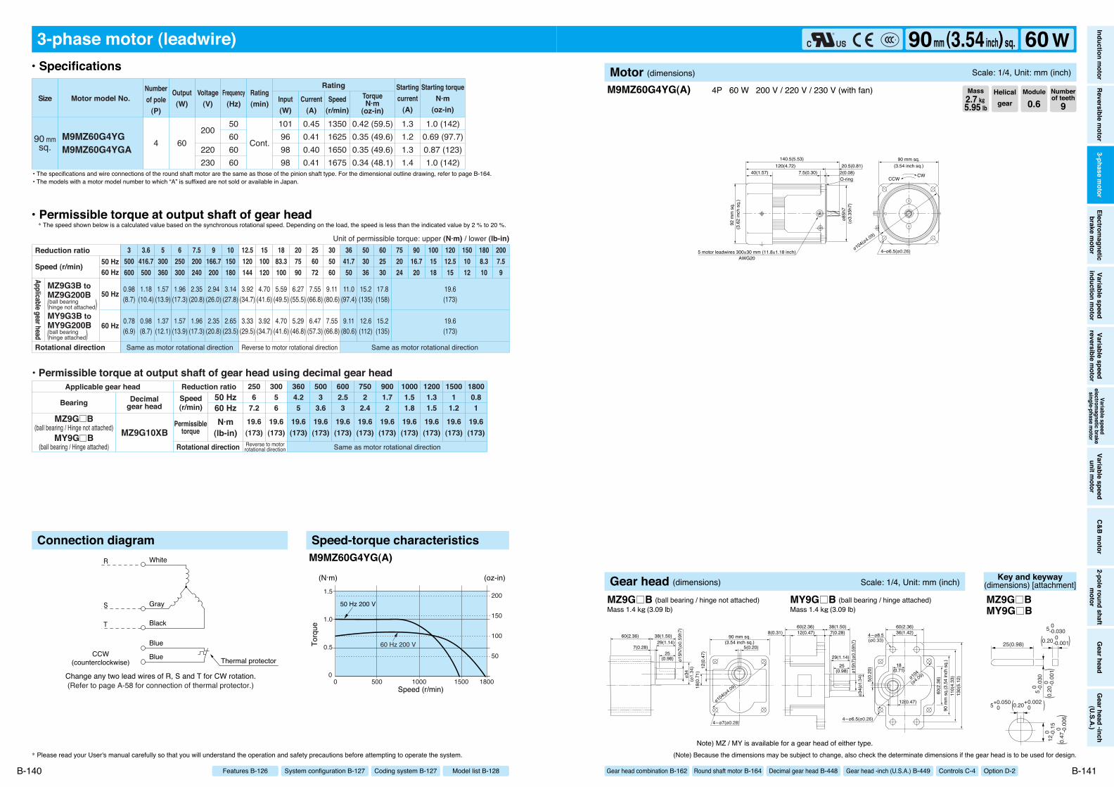
(Refer to page A-58 for connection of thermal protector.)
CCW(counterclockwise)
R
S
T
White
Gray
Black
Blue
Blue Thermal protector
Change any two lead wires of R, S and T for CW rotation.
3-phase motor (leadwire)
90 mmsq.
M9MZ60G4YGM9MZ60G4YGA
1.0 (142)0.69 (97.7)0.87 (123)1.0 (142)
0.42 (59.5)0.35 (49.6)0.35 (49.6)0.34 (48.1)
4 60
50606060
200
220230
101969898
0.450.410.400.41
1350162516501675
1.31.21.31.4
Cont.
Motor model No.Rating
SizeNumberof pole
(P)
Output(W)
Voltage(V)
Frequency(Hz)
Rating(min) Input
(W)Current
(A)
TorqueN·m
(oz-in)
Starting torqueN·m
(oz-in)
Startingcurrent
(A)Speed
(r/min)
Same as motor rotational direction
19.6(173)
19.6(173)
19.6(173)
19.6(173)
19.6(173)
19.6(173)
19.6(173)
19.6(173)
19.6(173)
19.6(173)
19.6(173)
6002.53
5003
3.6
2506
7.2
30056
3604.25
7502
2.4
9001.72
10001.51.8
12001.31.5
15001
1.2
18000.81
0.98(8.7)
1.18(10.4)
1.57(13.9)
1.96(17.3)
2.35(20.8)
2.94(26.0)
3.14(27.8)
3.92(34.7)
4.70(41.6)
5.59(49.5)
6.27(55.5)
7.55(66.8)
9.11(80.6)
11.0(97.4)
15.2(135)
17.8(158)
19.6(173)
0.78(6.9)
0.98(8.7)
1.37(12.1)
1.57(13.9)
1.96(17.3)
2.35(20.8)
2.65(23.5)
3.33(29.5)
3.92(34.7)
4.70(41.6)
5.29(46.8)
6.47(57.3)
7.55(66.8)
9.11(80.6)
12.6(112)
15.2(135)
19.6(173)
3500600
3.6416.7500
5300360
6250300
7.5200240
9166.7200
10150180
12.5120144
15100120
1883.3100
207590
256072
305060
3641.750
503036
602530
752024
9016.720
1001518
12012.515
1808.310
2007.59
1501012
Same as motor rotational direction Same as motor rotational directionReverse to motor rotational direction
Reverse to motorrotational direction
• Permissible torque at output shaft of gear head using decimal gear head
MZ9G10XBMZ9G B
(ball bearing / Hinge not attached)MY9G B
(ball bearing / Hinge attached)
Applicable gear head
Bearing Decimalgear head
Speed(r/min)
Permissibletorque
50 Hz60 HzN·m
(lb-in)Rotational direction
Reduction ratio
Reduction ratio
Rotational direction
Speed (r/min)
Unit of permissible torque: upper (N·m) / lower (lb-in)
MZ9G3B toMZ9G200B
MY9G3B toMY9G200B
Applicable gear head
ball bearing(hinge not attached)
ball bearing(hinge attached)
50 Hz60 Hz
50 Hz
60 Hz
Connection diagram Speed-torque characteristics
00 1800
1.5
1.0
0.5
15001000500
60 Hz 200 V
50 Hz 200 V
(N·m)
Speed (r/min)
Torq
ue
150
100
50
200
(oz-in)
M9MZ60G4YG(A)
* Please read your User's manual carefully so that you will understand the operation and safety precautions before attempting to operate the system.
B-140
• Specifications
• Permissible torque at output shaft of gear head* The speed shown below is a calculated value based on the synchronous rotational speed. Depending on the load, the speed is less than the indicated value by 2 % to 20 %.
• The specifications and wire connections of the round shaft motor are the same as those of the pinion shaft type. For the dimensional outline drawing, refer to page B-164.
Model list B-128Coding system B-127System configuration B-127Features B-126
• The models with a motor model number to which “A” is suffixed are not sold or available in Japan.
140.5(5.53)120(4.72) 20.5(0.81)
7.5(0.30)40(1.57) 2(0.08)
ø85h
7
CWCCW
5 motor leadwires 300±30 mm (11.8±1.18 inch)AWG20
92 m
m s
q.(3
.62
inch
sq.
)
4–ø6.5(ø0.26)ø104(ø4.09)
90 mm sq.(3.54 inch sq.)
(ø3.
35h7
)
O-ring
M9MZ60G4YG(A) 4P 60 W 200 V / 220 V / 230 V (with fan)
(Note) Because the dimensions may be subject to change, also check the determinate dimensions if the gear head is to be used for design.
B-141
Helicalgear
Module
0.6Numberof teeth
9Mass2.7 k""5.95 lb
Inductionm
otorReversible
motor
3-phasem
otorElectrom
agneticbrake
motor
Variablespeed
inductionm
otorVariable
speedreversible
motor
Variablespeed
electromagnetic
brakesingle-phase
motor
Variablespeed
unitmotor
C&Bm
otor2-pole
roundshaft
motor
Gearhead
Gearhead
-inch(U.S.A.)
90mm (3.54inch) sq. 60 WMotor (dimensions) Scale: 1/4, Unit: mm (inch)
Gear head combination B-162 Round shaft motor B-164 Decimal gear head B-448 Gear head -inch (U.S.A.) B-449 Controls C-4 Option D-2
Note) MZ / MY is available for a gear head of either type.
ø15h
7(ø0
.59h
7)ø3
4(ø
1.34
) 12(0
.47)
18(0
.71)
5(0.20)
90 mm sq.(3.54 inch sq.)
ø104(ø4.09)
4–ø7(ø0.28)
29(1.14)
25(0.98)
7(0.28)
60(2.36) 38(1.50)
5(0.
20)
ø34(
ø1.3
4)ø1
5h7(
ø0.5
9h7)
110(
4.33
)13
0(5.
12)
60(2.36)36(1.42)4–ø8.5
(ø0.33)
4–ø6.5(ø0.26)
60(2.36) 38(1.50)7(0.28)
29(1.14)
12(0.47)8(0.31)
25(0.98)
18(0.71)
12(0.47)
ø104
(ø4.09)
90 m
m s
q.(3
.54
inch
sq.
)60
(2.3
6)
Gear head (dimensions) Scale: 1/4, Unit: mm (inch)
MZ9G B (ball bearing / hinge not attached) MY9G B (ball bearing / hinge attached)Mass 1.4 k"(3.09 lb) Mass 1.4 k"(3.09 lb)
Key and keyway(dimensions) [attachment]
25(0.98)
5 0 -0.
030
12 0
-0
.15
5 0 -0.030
0.20 0 -0.001
5+0.050 0
( )
0.20
0
-0
.001
(
)
0.20+0.002 0( )
0.47
0
-0
.006
(
)
MZ9G BMY9G B

155.5(6.12)135(5.31) 20.5(0.81)
7.5(0.30)40(1.57) 2(0.08)
ø85h
7
92 m
m s
q.
3 motor leadwires 300±30 mm (11.8±1.18 inch)AWG20
CWCCW
(3.6
2 in
ch s
q.)
4–ø6.5(ø0.26)ø104(ø4.09)
90 mm sq.(3.54 inch sq.)
(ø3.
35h7
)
O-ring
Change any two lead wires of R, S and T for CW rotation.
R
S
T
White
Gray
Black
CCW(counterclockwise)
3-phase motor (leadwire)
90 mmsq. M9MZ90G4Y
1.6 (227)1.1 (156)2.0 (283)1.4 (198)
0.63 (89.2)0.53 (75.1)0.62 (87.8)0.52 (73.6)
4 90200
220
50605060
141137143137
0.620.560.650.56
1350162514001650
2.01.82.22.0
Cont.
Cont.
Motor model No.Rating
SizeNumberof pole
(P)
Output(W)
Voltage(V)
Frequency(Hz)
Rating(min) Input
(W)Current
(A)
TorqueN·m
(oz-in)
Starting torqueN·m
(oz-in)
Startingcurrent
(A)Speed
(r/min)
19.6(173)
19.6(173)
19.6(173)
19.6(173)
19.6(173)
19.6(173)
19.6(173)
19.6(173)
19.6(173)
19.6(173)
19.6(173)
6002.53
5003
3.6
2506
7.2
30056
3604.25
7502
2.4
9001.72
10001.51.8
12001.31.5
15001
1.2
18000.81
1.18(10.4)
1.37(12.1)
1.86(16.5)
2.25(19.9)
2.84(25.1)
3.43(30.4)
3.72(32.9)
4.70(41.6)
5.68(50.3)
6.76(59.8)
7.55(66.8)
9.21(81.5)
10.9(96.5)
13.0(115)
18.3(162)
19.6(173)
1.37(12.1)
1.67(14.8)
2.25(19.9)
2.74(24.3)
3.43(30.4)
4.12(36.5)
4.51(39.9)
5.68(50.3)
6.76(59.8)
8.04(71.2)
9.02(79.8)
10.9(96.5)
13.0(115)
15.7(139)
19.6(173)
19.6(173)
3500600
3.6416.7500
5300360
6250300
7.5200240
9166.7200
10150180
12.5120144
15100120
1883.3100
207590
256072
305060
3641.750
503036
602530
752024
9016.720
1001518
12012.515
1808.310
2007.59
1501012
Same as motor rotational directionReverse to motorrotational direction
• Permissible torque at output shaft of gear head using decimal gear head
MZ9G10XBMZ9G B
(ball bearing / hinge not attached)MY9G B
(ball bearing / hinge attached)
Applicable gear head
Bearing Decimalgear head
Speed(r/min)
Permissibletorque
50 Hz60 HzN·m
(lb-in)Rotational direction
Reduction ratio
Same as motor rotational direction Same as motor rotational directionReverse to motor rotational direction
Reduction ratio
Rotational direction
Speed (r/min)
Unit of permissible torque: upper (N·m) / lower (lb-in)
MZ9G3B toMZ9G200B
MY9G3B toMY9G200B
Applicable gear head
ball bearing(hinge not attached)
ball bearing(hinge attached)
50 Hz60 Hz
50 Hz
60 Hz
Connection diagram Speed-torque characteristics
0
2.0
2.5
1.5
1.0
0.5
0 180015001000500
60 Hz 200 V60 Hz 220 V
50 Hz 200 V
50 Hz 220 V
Speed (r/min)
Torq
ue
(oz-in)
200
100
300
(N·m)
M9MZ90G4Y
M9MZ90G4Y 4P 90 W 200 V / 220 V (with fan)
* Please read your User's manual carefully so that you will understand the operation and safety precautions before attempting to operate the system. (Note) Because the dimensions may be subject to change, also check the determinate dimensions if the gear head is to be used for design.
B-142 B-143
• Specifications
• Permissible torque at output shaft of gear head* The speed shown below is a calculated value based on the synchronous rotational speed. Depending on the load, the speed is less than the indicated value by 2 % to 20 %.
• The specifications and wire connections of the round shaft motor are the same as those of the pinion shaft type. For the dimensional outline drawing, refer to page B-164.
Helicalgear
Module
0.6Numberof teeth
9Mass3.2 k""7.05 lb
Model list B-128Coding system B-127System configuration B-127Features B-126
Inductionm
otorReversible
motor
3-phasem
otorElectrom
agneticbrake
motor
Variablespeed
inductionm
otorVariable
speedreversible
motor
Variablespeed
electromagnetic
brakesingle-phase
motor
Variablespeed
unitmotor
C&Bm
otor2-pole
roundshaft
motor
Gearhead
Gearhead
-inch(U.S.A.)
90mm (3.54inch) sq. 90 WMotor (dimensions) Scale: 1/4, Unit: mm (inch)
Gear head combination B-162 Round shaft motor B-164 Decimal gear head B-448 Gear head -inch (U.S.A.) B-449 Controls C-4 Option D-2
Note) MZ / MY is available for a gear head of either type.
ø15h
7(ø0
.59h
7)ø3
4(ø
1.34
) 12(0
.47)
18(0
.71)
5(0.20)
90 mm sq.(3.54 inch sq.)
ø104(ø4.09)
4–ø7(ø0.28)
29(1.14)
25(0.98)
7(0.28)
60(2.36) 38(1.50)
5(0.
20)
ø34(
ø1.3
4)ø1
5h7(
ø0.5
9h7)
110(
4.33
)13
0(5.
12)
60(2.36)36(1.42)4–ø8.5
(ø0.33)
4–ø6.5(ø0.26)
60(2.36) 38(1.50)7(0.28)
29(1.14)
12(0.47)8(0.31)
25(0.98)
18(0.71)
12(0.47)
ø104
(ø4.09)
90 m
m s
q.(3
.54
inch
sq.
)60
(2.3
6)
Gear head (dimensions) Scale: 1/4, Unit: mm (inch)
MZ9G B (ball bearing / hinge not attached) MY9G B (ball bearing / hinge attached)Mass 1.4 k"(3.09 lb) Mass 1.4 k"(3.09 lb)
Key and keyway(dimensions) [attachment]
25(0.98)
5 0 -0.
030
12 0
-0
.15
5 0 -0.030
0.20 0 -0.001
5+0.050 0
( )
0.20
0
-0
.001
(
)
0.20+0.002 0( )
0.47
0
-0
.006
(
)
MZ9G BMY9G B

(Refer to page A-58 for connection of thermal protector.)
CCW(counterclockwise)
R
S
T
White
Gray
Black
Blue
Blue Thermal protector
Change any two lead wires of R, S and T for CW rotation.
3-phase motor (leadwire)
90 mmsq.
M9MZ90G4YGM9MZ90G4YGA
1.6 (227)1.1 (156)1.4 (198)1.6 (227)
0.63 (89.2)0.53 (75.1)0.52 (73.6)0.51 (72.2)
4 90
50606060
200
220230
142138137137
0.620.560.560.58
1350162516501675
2.01.82.02.1
Cont.
Motor model No.Rating
SizeNumberof pole
(P)
Output(W)
Voltage(V)
Frequency(Hz)
Rating(min) Input
(W)Current
(A)
TorqueN·m
(oz-in)
Starting torqueN·m
(oz-in)
Startingcurrent
(A)Speed
(r/min)
19.6(173)
19.6(173)
19.6(173)
19.6(173)
19.6(173)
19.6(173)
19.6(173)
19.6(173)
19.6(173)
19.6(173)
19.6(173)
6002.53
5003
3.6
2506
7.2
30056
3604.25
7502
2.4
9001.72
10001.51.8
12001.31.5
15001
1.2
18000.81
1.18(10.4)
1.37(12.1)
1.86(16.5)
2.25(19.9)
2.84(25.1)
3.43(30.4)
3.72(32.9)
4.70(41.6)
5.68(50.3)
6.76(59.8)
7.55(66.8)
9.21(81.5)
10.9(96.5)
13.0(115)
18.3(162)
19.6(173)
1.37(12.1)
1.67(14.8)
2.25(19.9)
2.74(24.3)
3.43(30.4)
4.12(36.5)
4.51(39.9)
5.68(50.3)
6.76(59.8)
8.04(71.2)
9.02(79.8)
10.9(96.5)
13.0(115)
15.7(139)
19.6(173)
19.6(173)
3500600
3.6416.7500
5300360
6250300
7.5200240
9166.7200
10150180
12.5120144
15100120
1883.3100
207590
256072
305060
3641.750
503036
602530
752024
9016.720
1001518
12012.515
1808.310
2007.59
1501012
Same as motor rotational directionReverse to motorrotational direction
• Permissible torque at output shaft of gear head using decimal gear head
MZ9G10XBMZ9G B
(ball bearing / hinge not attached)MY9G B
(ball bearing / hinge attached)
Applicable gear head
Bearing Decimalgear head
Speed(r/min)
Permissibletorque
50 Hz60 HzN·m
(lb-in)Rotational direction
Reduction ratio
Same as motor rotational direction Same as motor rotational directionReverse to motor rotational direction
Reduction ratio
Rotational direction
Speed (r/min)
Unit of permissible torque: upper (N·m) / lower (lb-in)
MZ9G3B toMZ9G200B
MY9G3B toMY9G200B
Applicable gear head
ball bearing(hinge not attached)
ball bearing(hinge attached)
50 Hz60 Hz
50 Hz
60 Hz
Connection diagram Speed-torque characteristics
00 1800
2.0
1.5
1.0
0.5
15001000500
200 V 60 Hz
200 V 50 Hz
(N·m)
Speed (r/min)
Torq
ue
(oz-in)
100
200
M9MZ90G4YG(A)
* Please read your User's manual carefully so that you will understand the operation and safety precautions before attempting to operate the system.
B-144
• Specifications
• Permissible torque at output shaft of gear head* The speed shown below is a calculated value based on the synchronous rotational speed. Depending on the load, the speed is less than the indicated value by 2 % to 20 %.
• The specifications and wire connections of the round shaft motor are the same as those of the pinion shaft type. For the dimensional outline drawing, refer to page B-164.
Model list B-128Coding system B-127System configuration B-127Features B-126
• The models with a motor model number to which “A” is suffixed are not sold or available in Japan.
155.5(6.12)135(5.31) 20.5(0.81)
7.5(0.30)40(1.57) 2(0.08)
ø85h
7
92 m
m s
q.
5 motor leadwires 300±30 mm (11.8±1.18 inch)AWG20
CWCCW
(3.6
2 in
ch s
q.)
4–ø6.5(ø0.26)ø104(ø4.09)
90 mm sq.(3.54 inch sq.)
(ø3.
35h7
)
O-ring
M9MZ90G4YG(A) 4P 90 W 200 V / 220 V / 230 V (with fan)
(Note) Because the dimensions may be subject to change, also check the determinate dimensions if the gear head is to be used for design.
B-145
Helicalgear
Module
0.6Numberof teeth
9Mass3.2 k""7.05 lb
Inductionm
otorReversible
motor
3-phasem
otorElectrom
agneticbrake
motor
Variablespeed
inductionm
otorVariable
speedreversible
motor
Variablespeed
electromagnetic
brakesingle-phase
motor
Variablespeed
unitmotor
C&Bm
otor2-pole
roundshaft
motor
Gearhead
Gearhead
-inch(U.S.A.)
90mm (3.54inch) sq. 90 WMotor (dimensions) Scale: 1/4, Unit: mm (inch)
Gear head combination B-162 Round shaft motor B-164 Decimal gear head B-448 Gear head -inch (U.S.A.) B-449 Controls C-4 Option D-2
Note) MZ / MY is available for a gear head of either type.
ø15h
7(ø0
.59h
7)ø3
4(ø
1.34
) 12(0
.47)
18(0
.71)
5(0.20)
90 mm sq.(3.54 inch sq.)
ø104(ø4.09)
4–ø7(ø0.28)
29(1.14)
25(0.98)
7(0.28)
60(2.36) 38(1.50)
5(0.
20)
ø34(
ø1.3
4)ø1
5h7(
ø0.5
9h7)
110(
4.33
)13
0(5.
12)
60(2.36)36(1.42)4–ø8.5
(ø0.33)
4–ø6.5(ø0.26)
60(2.36) 38(1.50)7(0.28)
29(1.14)
12(0.47)8(0.31)
25(0.98)
18(0.71)
12(0.47)
ø104
(ø4.09)
90 m
m s
q.(3
.54
inch
sq.
)60
(2.3
6)
Gear head (dimensions) Scale: 1/4, Unit: mm (inch)
MZ9G B (ball bearing / hinge not attached) MY9G B (ball bearing / hinge attached)Mass 1.4 k"(3.09 lb) Mass 1.4 k"(3.09 lb)
Key and keyway(dimensions) [attachment]
25(0.98)
5 0 -0.
030
12 0
-0
.15
5 0 -0.030
0.20 0 -0.001
5+0.050 0
( )
0.20
0
-0
.001
(
)
0.20+0.002 0( )
0.47
0
-0
.006
(
)
MZ9G BMY9G B
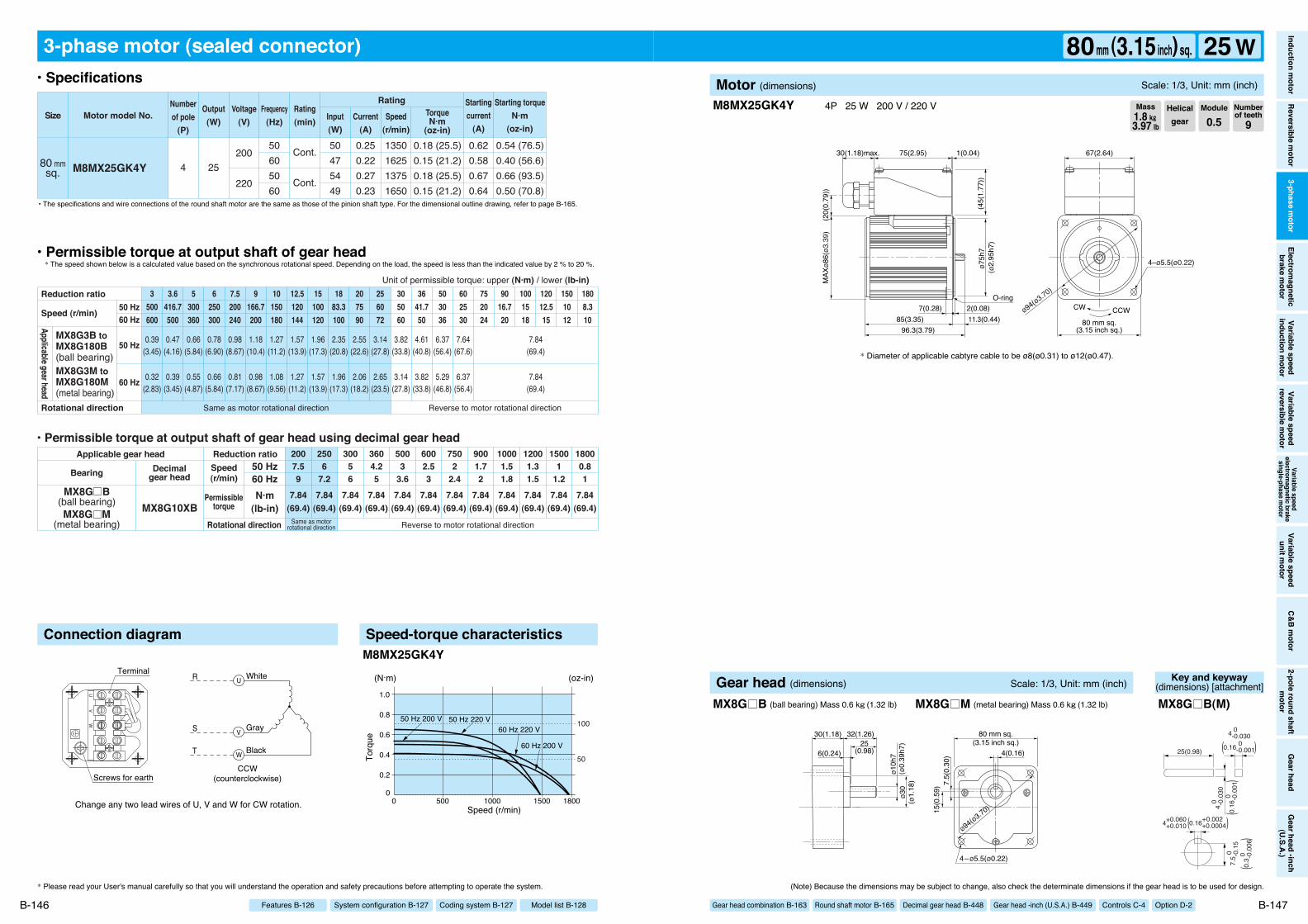
96.3(3.79)85(3.35)
75(2.95) 1(0.04)30(1.18)max.
11.3(0.44)7(0.28) 2(0.08)
ø75h
7
80 mm sq.(3.15 inch sq.)
ø94(ø3.70)
CCWCW
67(2.64)
MAX
ø86(
ø3.3
9)(2
0(0.
79))
(45(
1.77
))
4–ø5.5(ø0.22)
O-ring
(ø2.
95h7
)
Change any two lead wires of U, V and W for CW rotation.
R
S
T
White
Gray
Black
CCW(counterclockwise)
UV
W
Terminal
Screws for earth
W
V
U
3-phase motor (sealed connector)
80 mmsq. M8MX25GK4Y
0.54 (76.5)0.40 (56.6)0.66 (93.5)0.50 (70.8)
0.18 (25.5)0.15 (21.2)0.18 (25.5)0.15 (21.2)
4 25200
220
50605060
50475449
0.250.220.270.23
1350162513751650
0.620.580.670.64
Cont.
Cont.
Motor model No.Rating
SizeNumberof pole
(P)
Output(W)
Voltage(V)
Frequency(Hz)
Rating(min) Input
(W)Current
(A)
TorqueN·m
(oz-in)
Starting torqueN·m
(oz-in)
Startingcurrent
(A)Speed
(r/min)
7.84(69.4)
7.84(69.4)
7.84(69.4)
7.84(69.4)
7.84(69.4)
7.84(69.4)
7.84(69.4)
7.84(69.4)
7.84(69.4)
7.84(69.4)
7.84(69.4)
7.84(69.4)
6002.53
5003
3.6
2506
7.2
30056
3604.25
2007.59
7502
2.4
9001.72
10001.51.8
12001.31.5
15001
1.2
18000.81
0.39(3.45)
0.47(4.16)
0.66(5.84)
0.78(6.90)
0.98(8.67)
1.18(10.4)
1.27(11.2)
1.57(13.9)
1.96(17.3)
2.35(20.8)
2.55(22.6)
3.14(27.8)
3.82(33.8)
4.61(40.8)
6.37(56.4)
7.64(67.6)
7.84(69.4)
0.32(2.83)
0.39(3.45)
0.55(4.87)
0.66(5.84)
0.81(7.17)
0.98(8.67)
1.08(9.56)
1.27(11.2)
1.57(13.9)
1.96(17.3)
2.06(18.2)
2.65(23.5)
3.14(27.8)
3.82(33.8)
5.29(46.8)
6.37(56.4)
7.84(69.4)
3500600
3.6416.7500
5300360
6250300
7.5200240
9166.7200
10150180
12.5120144
15100120
1883.3100
207590
256072
305060
3641.750
503036
602530
752024
9016.720
1001518
12012.515
1501012
1808.310
• Permissible torque at output shaft of gear head using decimal gear head
MX8G10XBSame as motor
rotational direction Reverse to motor rotational direction
MX8G B(ball bearing)MX8G M
(metal bearing)
Same as motor rotational direction Reverse to motor rotational direction
Applicable gear head
Bearing Decimalgear head
Speed(r/min)
Permissibletorque
50 Hz60 HzN·m
(lb-in)Rotational direction
Reduction ratio
Reduction ratio
Rotational direction
Speed (r/min)
Unit of permissible torque: upper (N·m) / lower (lb-in)!
MX8G3B toMX8G180B(ball bearing)MX8G3M toMX8G180M(metal bearing)
Applicable gear head
50 Hz60 Hz
50 Hz
60 Hz
Connection diagram Speed-torque characteristics
00 1800
1.0
0.8
0.6
0.4
0.2
15001000500
60 Hz 200 V
60 Hz 220 V50 Hz 200 V 50 Hz 220 V
(N·m)
Speed (r/min)
Torq
ue
(oz-in)
100
50
M8MX25GK4Y
M8MX25GK4Y 4P 25 W 200 V / 220 V
* Please read your User's manual carefully so that you will understand the operation and safety precautions before attempting to operate the system. (Note) Because the dimensions may be subject to change, also check the determinate dimensions if the gear head is to be used for design.
B-146 B-147
• Specifications
• Permissible torque at output shaft of gear head* The speed shown below is a calculated value based on the synchronous rotational speed. Depending on the load, the speed is less than the indicated value by 2 % to 20 %.
• The specifications and wire connections of the round shaft motor are the same as those of the pinion shaft type. For the dimensional outline drawing, refer to page B-165.
* Diameter of applicable cabtyre cable to be ø8(ø0.31) to ø12(ø0.47).
Helicalgear
Module
0.5Numberof teeth
9Mass1.8 k""3.97 lb
Model list B-128Coding system B-127System configuration B-127Features B-126
Inductionm
otorReversible
motor
3-phasem
otorElectrom
agneticbrake
motor
Variablespeed
inductionm
otorVariable
speedreversible
motor
Variablespeed
electromagnetic
brakesingle-phase
motor
Variablespeed
unitmotor
C&Bm
otor2-pole
roundshaft
motor
Gearhead
Gearhead
-inch(U.S.A.)
80mm (3.15inch) sq. 25 WMotor (dimensions) Scale: 1/3, Unit: mm (inch)
Gear head combination B-163 Round shaft motor B-165 Decimal gear head B-448 Gear head -inch (U.S.A.) B-449 Controls C-4 Option D-2ø1
0h7
ø30
(ø1.
18)
(ø0.
39h7
)
7.5(
0.30
)15
(0.5
9)
4(0.16)
80 mm sq.(3.15 inch sq.)
ø94(ø3.70)
4–ø5.5(ø0.22)
30(1.18) 32(1.26)25
(0.98)6(0.24)
Gear head (dimensions) Scale: 1/3, Unit: mm (inch)
MX8G B (ball bearing) Mass 0.6 k"(1.32 lb) MX8G M (metal bearing) Mass 0.6 k"(1.32 lb)
Key and keyway(dimensions) [attachment]
25(0.98)
4 0 -0.
030
7.5 0
-
0.15
4 0 -0.030
0.16 0 -0.001
4+0.060 +0.010
( )
0.16
0
-0
.001
(
)
0.16+0.002 +0.0004( )
0.3 0
-
0.00
6(
)
MX8G B(M)

96.3(3.79)85(3.35)
75(2.95) 1(0.04)30(1.18)max.
11.3(0.44)7(0.28) 2(0.08)
ø75h
7
80 mm sq.(3.15 inch sq.)
ø94(ø3.70)
CCWCW
67(2.64)
MAX
ø86(
ø3.3
9)(2
0(0.
79))
(45(
1.77
))
4–ø5.5(ø0.22)
O-ring
(ø2.
95h7
)
(Refer to page A-58 for connection of thermal protector.)
PP
UV
W
Change any two lead wires of U, V and W for CW rotation.CCW (counterclockwise)
R
S
T
White
Gray
Black Thermal protectorBlue
Blue
Terminal
Screws for earth
W
V
U
P
P
3-phase motor (sealed connector)
M8MX25GK4YGM8MX25GK4YGA
M8MX25GK4CG *M8MX25GK4CGA
0.54 (76.5)
0.40 (56.6)
0.50 (70.8)
0.54 (76.5)
0.50 (70.8)
0.56 (79.3)
0.18 (25.5)
0.15 (21.2)
0.14 (19.8)
0.14 (19.8)
0.18 (25.5)
0.18 (25.5)
80 mmsq.
4
4
25
25
50
60
60
60
50
50
200
220
230
380
400
50
47
49
50
49
52
0.25
0.22
0.23
0.24
0.12
0.12
1350
1625
1650
1675
1325
1325
0.62
0.58
0.64
0.65
0.29
0.32
Cont.
Cont.
Motor model No.Rating
SizeNumberof pole
(P)
Output(W)
Voltage(V)
Frequency(Hz)
Rating(min) Input
(W)Current
(A)
TorqueN·m
(oz-in)
Starting torqueN·m
(oz-in)
Startingcurrent
(A)Speed
(r/min)
7.84(69.4)
7.84(69.4)
7.84(69.4)
7.84(69.4)
7.84(69.4)
7.84(69.4)
7.84(69.4)
7.84(69.4)
7.84(69.4)
7.84(69.4)
7.84(69.4)
7.84(69.4)
6002.53
5003
3.6
2506
7.2
30056
3604.25
2007.59
7502
2.4
9001.72
10001.51.8
12001.31.5
15001
1.2
18000.81
0.39(3.45)
0.47(4.16)
0.66(5.84)
0.78(6.90)
0.98(8.67)
1.18(10.4)
1.27(11.2)
1.57(13.9)
1.96(17.3)
2.35(20.8)
2.55(22.6)
3.14(27.8)
3.82(33.8)
4.61(40.8)
6.37(56.4)
7.64(67.6)
7.84(69.4)
0.32(2.83)
0.39(3.45)
0.55(4.87)
0.66(5.84)
0.81(7.17)
0.98(8.67)
1.08(9.56)
1.27(11.2)
1.57(13.9)
1.96(17.3)
2.06(18.2)
2.65(23.5)
3.14(27.8)
3.82(33.8)
5.29(46.8)
6.37(56.4)
7.84(69.4)
3500600
3.6416.7500
5300360
6250300
7.5200240
9166.7200
10150180
12.5120144
15100120
1883.3100
207590
256072
305060
3641.750
503036
602530
752024
9016.720
1001518
12012.515
1501012
1808.310
Same as motor rotational direction Reverse to motor rotational direction
Reduction ratio
Rotational direction
Speed (r/min)
Unit of permissible torque: upper (N·m) / lower (lb-in)
MX8G3B toMX8G180B(ball bearing)MX8G3M toMX8G180M(metal bearing)
Applicable gear head
• Permissible torque at output shaft of gear head using decimal gear head
MX8G10XBSame as motor
rotational direction Reverse to motor rotational direction
MX8G B(ball bearing)MX8G M
(metal bearing)
Applicable gear head
Bearing Decimalgear head
Speed(r/min)
Permissibletorque
50 Hz60 HzN·m
(lb-in)Rotational direction
Reduction ratio
50 Hz60 Hz
50 Hz
60 Hz
Connection diagram Speed-torque characteristics
00 1800
1.0
0.8
0.6
0.4
0.2
15001000500
(N·m)
Speed (r/min)
Torq
ue
(oz-in)
100
5060 Hz 200 V
50 Hz 400 V
50 Hz 200 V
50 Hz 380 V
M8MX25GK4YG(A) / M8MX25GK4CG(A)
M8MX25GK4YG(A)M8MX25GK4CG(A)
4P 25 W 200 V / 220 V / 230 V4P 25 W 380 V / 400 V
* Diameter of applicable cabtyre cable to be ø8(ø0.31) to ø12(ø0.47).
* Please read your User's manual carefully so that you will understand the operation and safety precautions before attempting to operate the system. (Note) Because the dimensions may be subject to change, also check the determinate dimensions if the gear head is to be used for design.
B-148 B-149
• Specifications
• Permissible torque at output shaft of gear head* The speed shown below is a calculated value based on the synchronous rotational speed. Depending on the load, the speed is less than the indicated value by 2 % to 20 %.
* Do not use an inverter to drive 380 V/400 V motor.• The specifications and wire connections of the round shaft motor are the same as those of the pinion shaft type. For the dimensional outline drawing, refer to page B-165.• The models with a motor model number to which “A” is suffixed are not sold or available in Japan.
Helicalgear
Module
0.5Numberof teeth
9Mass1.8 k""3.97 lb
Model list B-128Coding system B-127System configuration B-127Features B-126
Inductionm
otorReversible
motor
3-phasem
otorElectrom
agneticbrake
motor
Variablespeed
inductionm
otorVariable
speedreversible
motor
Variablespeed
electromagnetic
brakesingle-phase
motor
Variablespeed
unitmotor
C&Bm
otor2-pole
roundshaft
motor
Gearhead
Gearhead
-inch(U.S.A.)
80mm (3.15inch) sq. 25 WMotor (dimensions) Scale: 1/3, Unit: mm (inch)
Gear head combination B-163 Round shaft motor B-165 Decimal gear head B-448 Gear head -inch (U.S.A.) B-449 Controls C-4 Option D-2ø1
0h7
ø30
(ø1.
18)
(ø0.
39h7
)
7.5(
0.30
)15
(0.5
9)
4(0.16)
80 mm sq.(3.15 inch sq.)
ø94(ø3.70)
4–ø5.5(ø0.22)
30(1.18) 32(1.26)25
(0.98)6(0.24)
Gear head (dimensions) Scale: 1/3, Unit: mm (inch)
MX8G B (ball bearing) Mass 0.6 k"(1.32 lb) MX8G M (metal bearing) Mass 0.6 k"(1.32 lb)
Key and keyway(dimensions) [attachment]
25(0.98)
4 0 -0.
030
7.5 0
-
0.15
4 0 -0.030
0.16 0 -0.001
4+0.060 +0.010
( )
0.16
0
-0
.001
(
)
0.16+0.002 +0.0004( )
0.3 0
-
0.00
6(
)
MX8G B(M)

ø85h
7(4
5(1.
77))
117.8(4.64)105(4.13) 12.8(0.50)
7.5(0.30) 2(0.08)
75(2.95) 1(0.04)30(1.18)max.
MAX
ø95(
ø3.7
4)(2
0(0.
79))
CCWCW
67(2.64)
4–ø6.5(ø0.26)
90 mm sq.(3.54 inch sq.)
O-ringø104(ø4.09)
(ø3.
35h7
)
Change any two lead wires of U, V and W for CW rotation.
R
S
T
White
Gray
Black
CCW(counterclockwise)
UV
W
Terminal
Screws for earth
W
V
U
3-phase motor (sealed connector)
90 mmsq. M9MX40GK4Y
0.72 (102)0.51 (72.2)0.88 (125)0.63 (89.2)
0.28 (39.7)0.24 (34.0)0.27 (38.2)0.23 (32.6)
4 40200
220
50605060
69687066
0.310.290.320.28
1350162513751675
0.900.821.00.91
Cont.
Cont.
Motor model No.Rating
SizeNumberof pole
(P)
Output(W)
Voltage(V)
Frequency(Hz)
Rating(min) Input
(W)Current
(A)
TorqueN·m
(oz-in)
Starting torqueN·m
(oz-in)
Startingcurrent
(A)Speed
(r/min)
9.80(86.7)
9.80(86.7)
9.80(86.7)
9.80(86.7)
9.80(86.7)
9.80(86.7)
9.80(86.7)
9.80(86.7)
9.80(86.7)
9.80(86.7)
9.80(86.7)
9.80(86.7)
6002.53
5003
3.6
2506
7.2
30056
3604.25
2007.59
7502
2.4
9001.72
10001.51.8
12001.31.5
15001
1.2
18000.81
0.66(5.84)
0.78(6.90)
1.08(9.56)
1.27(11.2)
1.57(13.9)
1.86(16.5)
2.25(19.9)
2.74(24.3)
3.23(28.6)
3.92(34.7)
4.41(39.0)
5.29(46.8)
6.37(56.4)
7.94(70.3)
9.80(86.7)
9.80(86.7)
0.55(4.87)
0.66(5.84)
0.90(7.97)
1.08(9.56)
1.27(11.2)
1.57(13.9)
1.76(15.6)
2.25(19.9)
2.74(24.3)
3.23(28.6)
3.53(31.2)
4.41(39.0)
5.29(46.8)
6.37(56.4)
8.82(78.1)
9.80(86.7)
3500600
3.6416.7500
5300360
6250300
7.5200240
9166.7200
10150180
12.5120144
15100120
1883.3100
207590
256072
305060
3641.750
503036
602530
752024
9016.720
1001518
12012.515
1501012
1808.310
• Permissible torque at output shaft of gear head using decimal gear head
MX9G10XBSame as motor
rotational direction Reverse to motor rotational direction
MX9G B(ball bearing)MX9G M
(metal bearing)
Same as motor rotational direction Reverse to motor rotational direction
Applicable gear head
Bearing Decimalgear head
Speed(r/min)
Permissibletorque
50 Hz60 HzN·m
(lb-in)Rotational direction
Reduction ratio
Reduction ratio
Rotational direction
Speed (r/min)
Unit of permissible torque: upper (N·m) / lower (lb-in)
MX9G3B toMX9G180B(ball bearing)MX9G3M toMX9G180M(metal bearing)
Applicable gear head
50 Hz60 Hz
50 Hz
60 Hz
Connection diagram Speed-torque characteristics
00 1800
1.0
0.8
0.6
0.4
0.2
15001000500
60 Hz 200 V60 Hz 220 V
50 Hz 200 V50 Hz 220 V
(N·m)
Speed (r/min)
Torq
ue
(oz-in)
100
50
M9MX40GK4Y
M9MX40GK4Y 4P 40 W 200 V / 220 V
* Please read your User's manual carefully so that you will understand the operation and safety precautions before attempting to operate the system. (Note) Because the dimensions may be subject to change, also check the determinate dimensions if the gear head is to be used for design.
B-150 B-151
• Specifications
• Permissible torque at output shaft of gear head* The speed shown below is a calculated value based on the synchronous rotational speed. Depending on the load, the speed is less than the indicated value by 2 % to 20 %.
• The specifications and wire connections of the round shaft motor are the same as those of the pinion shaft type. For the dimensional outline drawing, refer to page B-165.
* Diameter of applicable cabtyre cable to be ø8(ø0.31) to ø12(ø0.47).
Helicalgear
Module
0.55Numberof teeth
9Mass2.8 k""6.17 lb
Model list B-128Coding system B-127System configuration B-127Features B-126
Inductionm
otorReversible
motor
3-phasem
otorElectrom
agneticbrake
motor
Variablespeed
inductionm
otorVariable
speedreversible
motor
Variablespeed
electromagnetic
brakesingle-phase
motor
Variablespeed
unitmotor
C&Bm
otor2-pole
roundshaft
motor
Gearhead
Gearhead
-inch(U.S.A.)
90mm (3.54inch) sq. 40 WMotor (dimensions) Scale: 1/3, Unit: mm (inch)
Gear head combination B-163 Round shaft motor B-165 Decimal gear head B-448 Gear head -inch (U.S.A.) B-449 Controls C-4 Option D-2
ø12h
7(ø0
.47)
ø36
(ø1.
42) 9.
5(0.
37)
18(0
.71)
4(0.16)
90 mm sq.(3.54 inch sq.)
ø104(ø4.09)
4–ø7(ø0.28)
37(1.46) 32(1.26)
25(0.98)
5(0.20)
Gear head (dimensions) Scale: 1/3, Unit: mm (inch)
MX9G B (ball bearing) Mass 0.8 k"(1.76 lb) MX9G M (metal bearing) Mass 0.8 k"(1.76 lb)
Key and keyway(dimensions) [attachment]
25(0.98)
4 0 -0.
030
9.5 0
-
0.15
4 0 -0.030
0.16 0 -0.001
4+0.060 +0.010
( )
0.16
0
-0
.001
(
)
0.16+0.002 +0.0004( )
0.37
0
-0
.006
(
)
MX9G B(M)
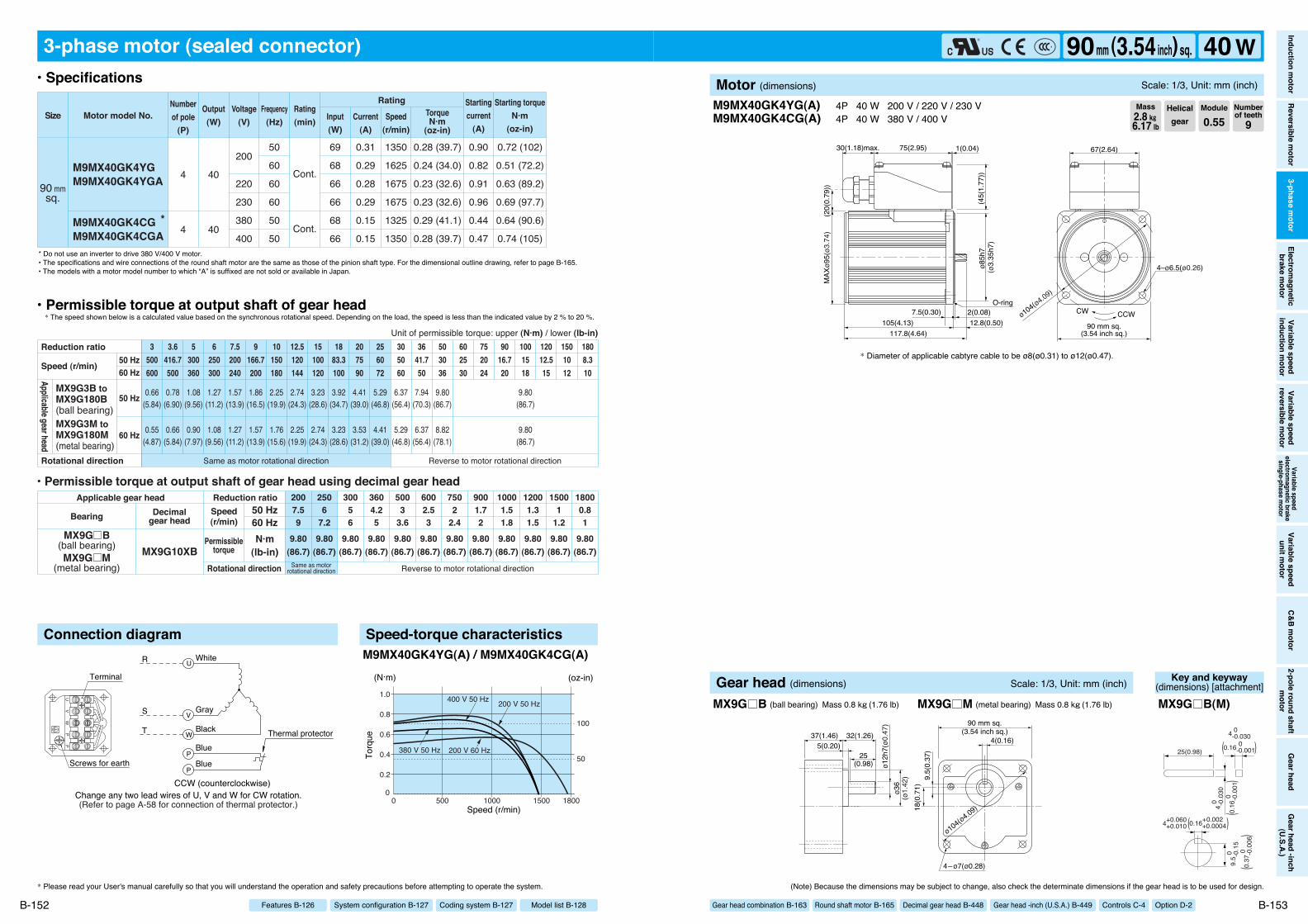
ø85h
7(4
5(1.
77))
117.8(4.64)105(4.13) 12.8(0.50)
7.5(0.30) 2(0.08)
75(2.95) 1(0.04)30(1.18)max.
MAX
ø95(
ø3.7
4)(2
0(0.
79))
CCWCW
67(2.64)
4–ø6.5(ø0.26)
90 mm sq.(3.54 inch sq.)
O-ringø104(ø4.09)
(ø3.
35h7
)
(Refer to page A-58 for connection of thermal protector.)
PP
UV
W
Change any two lead wires of U, V and W for CW rotation.CCW (counterclockwise)
R
S
T
White
Gray
Black Thermal protectorBlue
Blue
Terminal
Screws for earth
W
V
U
P
P
3-phase motor (sealed connector)
M9MX40GK4YGM9MX40GK4YGA
M9MX40GK4CG *M9MX40GK4CGA
0.72 (102)
0.51 (72.2)
0.63 (89.2)
0.69 (97.7)
0.64 (90.6)
0.74 (105)
0.28 (39.7)
0.24 (34.0)
0.23 (32.6)
0.23 (32.6)
0.29 (41.1)
0.28 (39.7)
90 mmsq.
4
4
40
40
50
60
60
60
50
50
200
220
230
380
400
69
68
66
66
68
66
0.31
0.29
0.28
0.29
0.15
0.15
1350
1625
1675
1675
1325
1350
0.90
0.82
0.91
0.96
0.44
0.47
Cont.
Cont.
Motor model No.Rating
SizeNumberof pole
(P)
Output(W)
Voltage(V)
Frequency(Hz)
Rating(min) Input
(W)Current
(A)
TorqueN·m
(oz-in)
Starting torqueN·m
(oz-in)
Startingcurrent
(A)Speed
(r/min)
9.80(86.7)
9.80(86.7)
9.80(86.7)
9.80(86.7)
9.80(86.7)
9.80(86.7)
9.80(86.7)
9.80(86.7)
9.80(86.7)
9.80(86.7)
9.80(86.7)
9.80(86.7)
6002.53
5003
3.6
2506
7.2
30056
3604.25
2007.59
7502
2.4
9001.72
10001.51.8
12001.31.5
15001
1.2
18000.81
0.66(5.84)
0.78(6.90)
1.08(9.56)
1.27(11.2)
1.57(13.9)
1.86(16.5)
2.25(19.9)
2.74(24.3)
3.23(28.6)
3.92(34.7)
4.41(39.0)
5.29(46.8)
6.37(56.4)
7.94(70.3)
9.80(86.7)
9.80(86.7)
0.55(4.87)
0.66(5.84)
0.90(7.97)
1.08(9.56)
1.27(11.2)
1.57(13.9)
1.76(15.6)
2.25(19.9)
2.74(24.3)
3.23(28.6)
3.53(31.2)
4.41(39.0)
5.29(46.8)
6.37(56.4)
8.82(78.1)
9.80(86.7)
3500600
3.6416.7500
5300360
6250300
7.5200240
9166.7200
10150180
12.5120144
15100120
1883.3100
207590
256072
305060
3641.750
503036
602530
752024
9016.720
1001518
12012.515
1501012
1808.310
Same as motor rotational direction Reverse to motor rotational direction
Reduction ratio
Rotational direction
Speed (r/min)
Unit of permissible torque: upper (N·m) / lower (lb-in)
MX9G3B toMX9G180B(ball bearing)MX9G3M toMX9G180M(metal bearing)
Applicable gear head
• Permissible torque at output shaft of gear head using decimal gear head
MX9G10XBSame as motor
rotational direction Reverse to motor rotational direction
MX9G B(ball bearing)MX9G M
(metal bearing)
Applicable gear head
Bearing Decimalgear head
Speed(r/min)
Permissibletorque
50 Hz60 HzN·m
(lb-in)Rotational direction
Reduction ratio
50 Hz60 Hz
50 Hz
60 Hz
Connection diagram Speed-torque characteristics
00 1800
1.0
0.8
0.6
0.4
0.2
15001000500
(N·m)
Speed (r/min)
Torq
ue
(oz-in)
100
50200 V 60 Hz380 V 50 Hz
200 V 50 Hz400 V 50 Hz
M9MX40GK4YG(A) / M9MX40GK4CG(A)
M9MX40GK4YG(A)M9MX40GK4CG(A)
4P 40 W 200 V / 220 V / 230 V4P 40 W 380 V / 400 V
* Diameter of applicable cabtyre cable to be ø8(ø0.31) to ø12(ø0.47).
* Please read your User's manual carefully so that you will understand the operation and safety precautions before attempting to operate the system. (Note) Because the dimensions may be subject to change, also check the determinate dimensions if the gear head is to be used for design.
B-152 B-153
• Specifications
• Permissible torque at output shaft of gear head* The speed shown below is a calculated value based on the synchronous rotational speed. Depending on the load, the speed is less than the indicated value by 2 % to 20 %.
* Do not use an inverter to drive 380 V/400 V motor.• The specifications and wire connections of the round shaft motor are the same as those of the pinion shaft type. For the dimensional outline drawing, refer to page B-165.• The models with a motor model number to which “A” is suffixed are not sold or available in Japan.
Helicalgear
Module
0.55Numberof teeth
9Mass2.8 k""6.17 lb
Model list B-128Coding system B-127System configuration B-127Features B-126
Inductionm
otorReversible
motor
3-phasem
otorElectrom
agneticbrake
motor
Variablespeed
inductionm
otorVariable
speedreversible
motor
Variablespeed
electromagnetic
brakesingle-phase
motor
Variablespeed
unitmotor
C&Bm
otor2-pole
roundshaft
motor
Gearhead
Gearhead
-inch(U.S.A.)
90mm (3.54inch) sq. 40 WMotor (dimensions) Scale: 1/3, Unit: mm (inch)
Gear head combination B-163 Round shaft motor B-165 Decimal gear head B-448 Gear head -inch (U.S.A.) B-449 Controls C-4 Option D-2
ø12h
7(ø0
.47)
ø36
(ø1.
42) 9.
5(0.
37)
18(0
.71)
4(0.16)
90 mm sq.(3.54 inch sq.)
ø104(ø4.09)
4–ø7(ø0.28)
37(1.46) 32(1.26)
25(0.98)
5(0.20)
Gear head (dimensions) Scale: 1/3, Unit: mm (inch)
MX9G B (ball bearing) Mass 0.8 k"(1.76 lb) MX9G M (metal bearing) Mass 0.8 k"(1.76 lb)
Key and keyway(dimensions) [attachment]
25(0.98)
4 0 -0.
030
9.5 0
-
0.15
4 0 -0.030
0.16 0 -0.001
4+0.060 +0.010
( )
0.16
0
-0
.001
(
)
0.16+0.002 +0.0004( )
0.37
0
-0
.006
(
)
MX9G B(M)

75(2.95) 1(0.04)30(1.18)max.
CCWCW
67(2.64)
140.5(5.53)120(4.72) 20.5(0.81)
7.5(0.30)40(1.57) 2(0.08)
ø85h
7
92 m
m s
q.
(45(
1.77
))
(20(
0.79
))
4–ø6.5(ø0.26)
90 mm sq.(3.54 inch sq.)
O-ring
(3.6
2 in
ch s
q.)
ø104(ø4.09)
(ø3.
35h7
)
Change any two lead wires of U, V and W for CW rotation.
R
S
T
White
Gray
Black
CCW(counterclockwise)
UV
W
Terminal
Screws for earth
W
V
U
3-phase motor (sealed connector)
90 mmsq. M9MZ60GK4Y
1.0 (142)0.69 (97.7)1.2 (170)0.87 (123)
0.42 (59.5)0.35 (49.6)0.41 (58.1)0.34 (48.1)
4 60200
220
50605060
10196
10398
0.450.410.460.40
1350162513751650
1.31.21.51.3
Cont.
Cont.
Motor model No.Rating
SizeNumberof pole
(P)
Output(W)
Voltage(V)
Frequency(Hz)
Rating(min) Input
(W)Current
(A)
TorqueN·m
(oz-in)
Starting torqueN·m
(oz-in)
Startingcurrent
(A)Speed
(r/min)
Same as motor rotational direction
19.6(173)
19.6(173)
19.6(173)
19.6(173)
19.6(173)
19.6(173)
19.6(173)
19.6(173)
19.6(173)
19.6(173)
19.6(173)
6002.53
5003
3.6
2506
7.2
30056
3604.25
7502
2.4
9001.72
10001.51.8
12001.31.5
15001
1.2
18000.81
0.98(8.7)
1.18(10.4)
1.57(13.9)
1.96(17.3)
2.35(20.8)
2.94(26.0)
3.14(27.8)
3.92(34.7)
4.70(41.6)
5.59(49.5)
6.27(55.5)
7.55(66.8)
9.11(80.6)
11.0(97.4)
15.2(135)
17.8(158)
19.6(173)
0.78(6.9)
0.98(8.7)
1.37(12.1)
1.57(13.9)
1.96(17.3)
2.35(20.8)
2.65(23.5)
3.33(29.5)
3.92(34.7)
4.70(41.6)
5.29(46.8)
6.47(57.3)
7.55(66.8)
9.11(80.6)
12.6(112)
15.2(135)
19.6(173)
3500600
3.6416.7500
5300360
6250300
7.5200240
9166.7200
10150180
12.5120144
15100120
1883.3100
207590
256072
305060
3641.750
503036
602530
752024
9016.720
1001518
12012.515
1808.310
2007.59
1501012
Same as motor rotational direction Same as motor rotational directionReverse to motor rotational direction
Reverse to motorrotational direction
• Permissible torque at output shaft of gear head using decimal gear head
MZ9G10XBMZ9G B
(ball bearing / Hinge not attached)MY9G B
(ball bearing / Hinge attached)
Applicable gear head
Bearing Decimalgear head
Speed(r/min)
Permissibletorque
50 Hz60 HzN·m
(lb-in)Rotational direction
Reduction ratio
Reduction ratio
Rotational direction
Speed (r/min)
Unit of permissible torque: upper (N·m) / lower (lb-in)
MZ9G3B toMZ9G200B
MY9G3B toMY9G200B
Applicable gear head
ball bearing(hinge not attached)
ball bearing(hinge attached)
50 Hz60 Hz
50 Hz
60 Hz
Connection diagram Speed-torque characteristics
00 1800
2.0
1.5
1.0
0.5
15001000500
50 Hz 200 V
50 Hz 220 V
60 Hz 200 V60 Hz 220 V
(N·m)
Speed (r/min)
Torq
ue
(oz-in)
100
200
M9MZ60GK4Y
M9MZ60GK4Y 4P 60 W 200 V / 220 V (with fan)
* Please read your User's manual carefully so that you will understand the operation and safety precautions before attempting to operate the system. (Note) Because the dimensions may be subject to change, also check the determinate dimensions if the gear head is to be used for design.
B-154 B-155
• Specifications
• Permissible torque at output shaft of gear head* The speed shown below is a calculated value based on the synchronous rotational speed. Depending on the load, the speed is less than the indicated value by 2 % to 20 %.
• The specifications and wire connections of the round shaft motor are the same as those of the pinion shaft type. For the dimensional outline drawing, refer to page B-165.
* Diameter of applicable cabtyre cable to be ø8(ø0.31) to ø12(ø0.47).
Helicalgear
Module
0.6Numberof teeth
9Mass3.0 k""6.61 lb
Model list B-128Coding system B-127System configuration B-127Features B-126
Inductionm
otorReversible
motor
3-phasem
otorElectrom
agneticbrake
motor
Variablespeed
inductionm
otorVariable
speedreversible
motor
Variablespeed
electromagnetic
brakesingle-phase
motor
Variablespeed
unitmotor
C&Bm
otor2-pole
roundshaft
motor
Gearhead
Gearhead
-inch(U.S.A.)
90mm (3.54inch) sq. 60 WMotor (dimensions) Scale: 1/4, Unit: mm (inch)
Gear head combination B-163 Round shaft motor B-165 Decimal gear head B-448 Gear head -inch (U.S.A.) B-449 Controls C-4 Option D-2
Note) MZ / MY is available for a gear head of either type.
ø15h
7(ø0
.59h
7)ø3
4(ø
1.34
) 12(0
.47)
18(0
.71)
5(0.20)
90 mm sq.(3.54 inch sq.)
ø104(ø4.09)
4–ø7(ø0.28)
29(1.14)
25(0.98)
7(0.28)
60(2.36) 38(1.50)
5(0.
20)
ø34(
ø1.3
4)ø1
5h7(
ø0.5
9h7)
110(
4.33
)13
0(5.
12)
60(2.36)36(1.42)4–ø8.5
(ø0.33)
4–ø6.5(ø0.26)
60(2.36) 38(1.50)7(0.28)
29(1.14)
12(0.47)8(0.31)
25(0.98)
18(0.71)
12(0.47)
ø104
(ø4.09)
90 m
m s
q.(3
.54
inch
sq.
)60
(2.3
6)
Gear head (dimensions) Scale: 1/4, Unit: mm (inch)
MZ9G B (ball bearing / hinge not attached) MY9G B (ball bearing / hinge attached)Mass 1.4 k"(3.09 lb) Mass 1.4 k"(3.09 lb)
Key and keyway(dimensions) [attachment]
25(0.98)
5 0 -0.
030
12 0
-0
.15
5 0 -0.030
0.20 0 -0.001
5+0.050 0
( )
0.20
0
-0
.001
(
)
0.20+0.002 0( )
0.47
0
-0
.006
(
)
MZ9G BMY9G B

75(2.95) 1(0.04)30(1.18)max.
CCWCW
67(2.64)
140.5(5.53)120(4.72) 20.5(0.81)
7.5(0.30)40(1.57) 2(0.08)
ø85h
7
92 m
m s
q.
(45(
1.77
))
(20(
0.79
))
4–ø6.5(ø0.26)
90 mm sq.(3.54 inch sq.)
O-ring
(3.6
2 in
ch s
q.)
ø104(ø4.09)
(ø3.
35h7
)
M9MZ60GK4YG(A)M9MZ60GK4CG(A)
4P 60 W 200 V / 220 V / 230 V (with fan) 4P 60 W 380 V / 400 V (with fan)
* Diameter of applicable cabtyre cable to be ø8(ø0.31) to ø12(ø0.47).
(Note) Because the dimensions may be subject to change, also check the determinate dimensions if the gear head is to be used for design.
B-157
Helicalgear
Module
0.6Numberof teeth
9Mass3.0 k""6.61 lb
Inductionm
otorReversible
motor
3-phasem
otorElectrom
agneticbrake
motor
Variablespeed
inductionm
otorVariable
speedreversible
motor
Variablespeed
electromagnetic
brakesingle-phase
motor
Variablespeed
unitmotor
C&Bm
otor2-pole
roundshaft
motor
Gearhead
Gearhead
-inch(U.S.A.)
90mm (3.54inch) sq. 60 WMotor (dimensions) Scale: 1/4, Unit: mm (inch)
Gear head combination B-163 Round shaft motor B-165 Decimal gear head B-448 Gear head -inch (U.S.A.) B-449 Controls C-4 Option D-2
(Refer to page A-58 for connection of thermal protector.)
PP
UV
W
Change any two lead wires of U, V and W for CW rotation.CCW (counterclockwise)
R
S
T
White
Gray
Black Thermal protectorBlue
Blue
Terminal
Screws for earth
W
V
U
P
P
3-phase motor (sealed connector)
M9MZ60GK4YGM9MZ60GK4YGA
M9MZ60GK4CG *M9MZ60GK4CGA
1.0 (142)
0.69 (97.7)
0.87 (123)
1.0 (142)
0.88 (125)
1.0 (142)
0.42 (59.5)
0.35 (49.6)
0.35 (49.6)
0.34 (48.1)
0.43 (60.9)
0.43 (60.9)
90 mmsq.
4
4
60
60
50
60
60
60
50
50
200
220
230
380
400
101
96
98
98
98
98
0.45
0.41
0.40
0.41
0.22
0.22
1350
1625
1650
1675
1325
1325
1.3
1.2
1.3
1.4
0.62
0.65
Cont.
Cont.
Motor model No.Rating
SizeNumberof pole
(P)
Output(W)
Voltage(V)
Frequency(Hz)
Rating(min) Input
(W)Current
(A)
TorqueN·m
(oz-in)
Starting torqueN·m
(oz-in)
Startingcurrent
(A)Speed
(r/min)
19.6(173)
19.6(173)
19.6(173)
19.6(173)
19.6(173)
19.6(173)
19.6(173)
19.6(173)
19.6(173)
19.6(173)
19.6(173)
6002.53
5003
3.6
2506
7.2
30056
3604.25
7502
2.4
9001.72
10001.51.8
12001.31.5
15001
1.2
18000.81
0.98(8.7)
1.18(10.4)
1.57(13.9)
1.96(17.3)
2.35(20.8)
2.94(26.0)
3.14(27.8)
3.92(34.7)
4.70(41.6)
5.59(49.5)
6.27(55.5)
7.55(66.8)
9.11(80.6)
11.0(97.4)
15.2(135)
17.8(158)
19.6(173)
0.78(6.9)
0.98(8.7)
1.37(12.1)
1.57(13.9)
1.96(17.3)
2.35(20.8)
2.65(23.5)
3.33(29.5)
3.92(34.7)
4.70(41.6)
5.29(46.8)
6.47(57.3)
7.55(66.8)
9.11(80.6)
12.6(112)
15.2(135)
19.6(173)
3500600
3.6416.7500
5300360
6250300
7.5200240
9166.7200
10150180
12.5120144
15100120
1883.3100
207590
256072
305060
3641.750
503036
602530
752024
9016.720
1001518
12012.515
1808.310
2007.59
1501012
Same as motor rotational directionReverse to motorrotational direction
• Permissible torque at output shaft of gear head using decimal gear head
MZ9G10XBMZ9G B
(ball bearing / hinge not attached)MY9G B
(ball bearing / hinge attached)
Applicable gear head
Bearing Decimalgear head
Speed(r/min)
Permissibletorque
50 Hz60 HzN·m
(lb-in)Rotational direction
Reduction ratio
Same as motor rotational direction Same as motor rotational directionReverse to motor rotational direction
Reduction ratio
Rotational direction
Speed (r/min)
Unit of permissible torque: upper (N·m) / lower (lb-in)
MZ9G3B toMZ9G200B
MY9G3B toMY9G200B
Applicable gear head
ball bearing(hinge not attached)
ball bearing(hinge attached)
50 Hz60 Hz
50 Hz
60 Hz
Connection diagram Speed-torque characteristics
00 1800
1.5
1.0
0.5
15001000500
(N·m)
Speed (r/min)
Torq
ue
150
100
50
200
(oz-in)
60 Hz 200 V
50 Hz 200 V 50 Hz 400 V
50 Hz 380 V
M9MZ60GK4YG(A) / M9MZ60GK4CG(A)
* Please read your User's manual carefully so that you will understand the operation and safety precautions before attempting to operate the system.
B-156
• Specifications
• Permissible torque at output shaft of gear head* The speed shown below is a calculated value based on the synchronous rotational speed. Depending on the load, the speed is less than the indicated value by 2 % to 20 %.
* Do not use an inverter to drive 380 V/400 V motor.• The specifications and wire connections of the round shaft motor are the same as those of the pinion shaft type. For the dimensional outline drawing, refer to page B-165.• The models with a motor model number to which “A” is suffixed are not sold or available in Japan.
Model list B-128Coding system B-127System configuration B-127Features B-126
Note) MZ / MY is available for a gear head of either type.
ø15h
7(ø0
.59h
7)ø3
4(ø
1.34
) 12(0
.47)
18(0
.71)
5(0.20)
90 mm sq.(3.54 inch sq.)
ø104(ø4.09)
4–ø7(ø0.28)
29(1.14)
25(0.98)
7(0.28)
60(2.36) 38(1.50)
5(0.
20)
ø34(
ø1.3
4)ø1
5h7(
ø0.5
9h7)
110(
4.33
)13
0(5.
12)
60(2.36)36(1.42)4–ø8.5
(ø0.33)
4–ø6.5(ø0.26)
60(2.36) 38(1.50)7(0.28)
29(1.14)
12(0.47)8(0.31)
25(0.98)
18(0.71)
12(0.47)
ø104
(ø4.09)
90 m
m s
q.(3
.54
inch
sq.
)60
(2.3
6)
Gear head (dimensions) Scale: 1/4, Unit: mm (inch)
MZ9G B (ball bearing / hinge not attached) MY9G B (ball bearing / hinge attached)Mass 1.4 k"(3.09 lb) Mass 1.4 k"(3.09 lb)
Key and keyway(dimensions) [attachment]
25(0.98)
5 0 -0.
030
12 0
-0
.15
5 0 -0.030
0.20 0 -0.001
5+0.050 0
( )
0.20
0
-0
.001
(
)
0.20+0.002 0( )
0.47
0
-0
.006
(
)
MZ9G BMY9G B

90 mm sq.(3.54 inch sq.)
75(2.95) 1(0.04)30(1.18)max.
4–ø6.5(ø0.26)
CCWCW
67(2.64)
155.5(6.12)135(5.31) 20.5(0.81)
7.5(0.30)40(1.57) 2(0.08)
ø85h
7
92 m
m s
q.
O-ring
(45(
1.77
))
(20(
0.79
))(3
.62
inch
sq.
)
ø104(ø4.09)
(ø3.
35h7
)
Change any two lead wires of U, V and W for CW rotation.
R
S
T
White
Gray
Black
CCW(counterclockwise)
UV
W
Terminal
Screws for earth
W
V
U
3-phase motor (sealed connector)
90 mmsq. M9MZ90GK4Y
1.6 (227)1.1 (156)2.0 (283)1.4 (198)
0.63 (89.2)0.53 (75.1)0.62 (87.8)0.52 (73.6)
4 90200
220
50605060
141137143137
0.620.560.650.56
1350162514001650
2.01.82.22.0
Cont.
Cont.
Motor model No.Rating
SizeNumberof pole
(P)
Output(W)
Voltage(V)
Frequency(Hz)
Rating(min) Input
(W)Current
(A)
TorqueN·m
(oz-in)
Starting torqueN·m
(oz-in)
Startingcurrent
(A)Speed
(r/min)
19.6(173)
19.6(173)
19.6(173)
19.6(173)
19.6(173)
19.6(173)
19.6(173)
19.6(173)
19.6(173)
19.6(173)
19.6(173)
6002.53
5003
3.6
2506
7.2
30056
3604.25
7502
2.4
9001.72
10001.51.8
12001.31.5
15001
1.2
18000.81
1.18(10.4)
1.37(12.1)
1.86(16.5)
2.25(19.9)
2.84(25.1)
3.43(30.4)
3.72(32.9)
4.70(41.6)
5.68(50.3)
6.76(59.8)
7.55(66.8)
9.21(81.5)
10.9(96.5)
13.0(115)
18.3(162)
19.6(173)
1.37(12.1)
1.67(14.8)
2.25(19.9)
2.74(24.3)
3.43(30.4)
4.12(36.5)
4.51(39.9)
5.68(50.3)
6.76(59.8)
8.04(71.2)
9.02(79.8)
10.9(96.5)
13.0(115)
15.7(139)
19.6(173)
19.6(173)
3500600
3.6416.7500
5300360
6250300
7.5200240
9166.7200
10150180
12.5120144
15100120
1883.3100
207590
256072
305060
3641.750
503036
602530
752024
9016.720
1001518
12012.515
1808.310
2007.59
1501012
Same as motor rotational directionReverse to motorrotational direction
• Permissible torque at output shaft of gear head using decimal gear head
MZ9G10XBMZ9G B
(ball bearing / hinge not attached)MY9G B
(ball bearing / hinge attached)
Applicable gear head
Bearing Decimalgear head
Speed(r/min)
Permissibletorque
50 Hz60 HzN·m
(lb-in)Rotational direction
Reduction ratio
Same as motor rotational direction Same as motor rotational directionReverse to motor rotational direction
Reduction ratio
Rotational direction
Speed (r/min)
Unit of permissible torque: upper (N·m) / lower (lb-in)
MZ9G3B toMZ9G200B
MY9G3B toMY9G200B
Applicable gear head
ball bearing(hinge not attached)
ball bearing(hinge attached)
50 Hz60 Hz
50 Hz
60 Hz
Connection diagram Speed-torque characteristics
0
0.5
2.0
2.5
1.5
1.0
0 180015001000500
50 Hz 200 V
50 Hz 220 V
60 Hz 200 V60 Hz 220 V
(N·m)
Speed (r/min)
Torq
ue
(oz-in)
200
100
300
M9MZ90GK4Y
M9MZ90GK4Y 4P 90 W 200 V / 220 V (with fan)
* Please read your User's manual carefully so that you will understand the operation and safety precautions before attempting to operate the system. (Note) Because the dimensions may be subject to change, also check the determinate dimensions if the gear head is to be used for design.
B-158 B-159
• Specifications
• Permissible torque at output shaft of gear head* The speed shown below is a calculated value based on the synchronous rotational speed. Depending on the load, the speed is less than the indicated value by 2 % to 20 %.
• The specifications and wire connections of the round shaft motor are the same as those of the pinion shaft type. For the dimensional outline drawing, refer to page B-165.
* Diameter of applicable cabtyre cable to be ø8(ø0.31) to ø12(ø0.47).
Helicalgear
Module
0.6Numberof teeth
9Mass3.3 k""7.28 lb
Model list B-128Coding system B-127System configuration B-127Features B-126
Inductionm
otorReversible
motor
3-phasem
otorElectrom
agneticbrake
motor
Variablespeed
inductionm
otorVariable
speedreversible
motor
Variablespeed
electromagnetic
brakesingle-phase
motor
Variablespeed
unitmotor
C&Bm
otor2-pole
roundshaft
motor
Gearhead
Gearhead
-inch(U.S.A.)
90mm (3.54inch) sq. 90 WMotor (dimensions) Scale: 1/4, Unit: mm (inch)
Gear head combination B-163 Round shaft motor B-165 Decimal gear head B-448 Gear head -inch (U.S.A.) B-449 Controls C-4 Option D-2
Note) MZ / MY is available for a gear head of either type.
ø15h
7(ø0
.59h
7)ø3
4(ø
1.34
) 12(0
.47)
18(0
.71)
5(0.20)
90 mm sq.(3.54 inch sq.)
ø104(ø4.09)
4–ø7(ø0.28)
29(1.14)
25(0.98)
7(0.28)
60(2.36) 38(1.50)
5(0.
20)
ø34(
ø1.3
4)ø1
5h7(
ø0.5
9h7)
110(
4.33
)13
0(5.
12)
60(2.36)36(1.42)4–ø8.5
(ø0.33)
4–ø6.5(ø0.26)
60(2.36) 38(1.50)7(0.28)
29(1.14)
12(0.47)8(0.31)
25(0.98)
18(0.71)
12(0.47)
ø104
(ø4.09)
90 m
m s
q.(3
.54
inch
sq.
)60
(2.3
6)
Gear head (dimensions) Scale: 1/4, Unit: mm (inch)
MZ9G B (ball bearing / hinge not attached) MY9G B (ball bearing / hinge attached)Mass 1.4 k"(3.09 lb) Mass 1.4 k"(3.09 lb)
Key and keyway(dimensions) [attachment]
25(0.98)
5 0 -0.
030
12 0
-0
.15
5 0 -0.030
0.20 0 -0.001
5+0.050 0
( )
0.20
0
-0
.001
(
)
0.20+0.002 0( )
0.47
0
-0
.006
(
)
MZ9G BMY9G B

90 mm sq.(3.54 inch sq.)
75(2.95) 1(0.04)30(1.18)max.
4–ø6.5(ø0.26)
CCWCW
67(2.64)
155.5(6.12)135(5.31) 20.5(0.81)
7.5(0.30)40(1.57) 2(0.08)
ø85h
7
92 m
m s
q.
O-ring
(45(
1.77
))
(20(
0.79
))(3
.62
inch
sq.
)
ø104(ø4.09)
(ø3.
35h7
)
(Refer to page A-58 for connection of thermal protector.)
PP
UV
W
Change any two lead wires of U, V and W for CW rotation.CCW (counterclockwise)
R
S
T
White
Gray
Black Thermal protectorBlue
Blue
Terminal
Screws for earth
W
V
U
P
P
3-phase motor (sealed connector)
M9MZ90GK4YGM9MZ90GK4YGA
M9MZ90GK4CG *M9MZ90GK4CGA
1.6 (227)
1.1 (156)
1.4 (198)
1.6 (227)
1.4 (198)
1.6 (227)
0.63 (89.2)
0.53 (75.1)
0.52 (73.6)
0.51 (72.2)
0.65 (92.0)
0.64 (90.6)
90 mmsq.
4
4
90
90
50
60
60
60
50
50
200
220
230
380
400
142
138
137
137
144
144
0.62
0.56
0.56
0.58
0.31
0.31
1350
1625
1650
1675
1325
1350
2.0
1.8
2.0
2.1
1.0
1.0
Cont.
Cont.
Motor model No.Rating
SizeNumberof pole
(P)
Output(W)
Voltage(V)
Frequency(Hz)
Rating(min) Input
(W)Current
(A)
TorqueN·m
(oz-in)
Starting torqueN·m
(oz-in)
Startingcurrent
(A)Speed
(r/min)
19.6(173)
19.6(173)
19.6(173)
19.6(173)
19.6(173)
19.6(173)
19.6(173)
19.6(173)
19.6(173)
19.6(173)
19.6(173)
6002.53
5003
3.6
2506
7.2
30056
3604.25
7502
2.4
9001.72
10001.51.8
12001.31.5
15001
1.2
18000.81
1.18(10.4)
1.37(12.1)
1.86(16.5)
2.25(19.9)
2.84(25.1)
3.43(30.4)
3.72(32.9)
4.70(41.6)
5.68(50.3)
6.76(59.8)
7.55(66.8)
9.21(81.5)
10.9(96.5)
13.0(115)
18.3(162)
19.6(173)
1.37(12.1)
1.67(14.8)
2.25(19.9)
2.74(24.3)
3.43(30.4)
4.12(36.5)
4.51(39.9)
5.68(50.3)
6.76(59.8)
8.04(71.2)
9.02(79.8)
10.9(96.5)
13.0(115)
15.7(139)
19.6(173)
19.6(173)
3500600
3.6416.7500
5300360
6250300
7.5200240
9166.7200
10150180
12.5120144
15100120
1883.3100
207590
256072
305060
3641.750
503036
602530
752024
9016.720
1001518
12012.515
1808.310
2007.59
1501012
Same as motor rotational directionReverse to motorrotational direction
• Permissible torque at output shaft of gear head using decimal gear head
MZ9G10XBMZ9G B
(ball bearing / hinge not attached)MY9G B
(ball bearing / hinge attached)
Applicable gear head
Bearing Decimalgear head
Speed(r/min)
Permissibletorque
50 Hz60 HzN·m
(lb-in)Rotational direction
Reduction ratio
Same as motor rotational direction Same as motor rotational directionReverse to motor rotational direction
50 Hz60 Hz
50 Hz
60 Hz
Reduction ratio
Rotational direction
Speed (r/min)
Unit of permissible torque: upper (N·m) / lower (lb-in)
MZ9G3B toMZ9G200B
MY9G3B toMY9G200B
Applicable gear head
ball bearing(hinge not attached)
ball bearing(hinge attached)
Connection diagram Speed-torque characteristics
00 1800
2.0
1.5
1.0
0.5
15001000500
(N·m)
Speed (r/min)
Torq
ue
(oz-in)
100
200
200 V 60 Hz380 V 50 Hz
200 V 50 Hz400 V 50 Hz
M9MZ90GK4YG(A) / M9MZ90GK4CG(A)
M9MZ90GK4YG(A)M9MZ90GK4CG(A)
4P 90 W 200 V / 220 V / 230 V (with fan) 4P 90 W 380 V / 400 V (with fan)
* Diameter of applicable cabtyre cable to be ø8(ø0.31) to ø12(ø0.47).
* Please read your User's manual carefully so that you will understand the operation and safety precautions before attempting to operate the system. (Note) Because the dimensions may be subject to change, also check the determinate dimensions if the gear head is to be used for design.
B-160 B-161
• Specifications
• Permissible torque at output shaft of gear head* The speed shown below is a calculated value based on the synchronous rotational speed. Depending on the load, the speed is less than the indicated value by 2 % to 20 %.
* Do not use an inverter to drive 380 V/400 V motor.• The specifications and wire connections of the round shaft motor are the same as those of the pinion shaft type. For the dimensional outline drawing, refer to page B-165.• The models with a motor model number to which “A” is suffixed are not sold or available in Japan.
Helicalgear
Module
0.6Numberof teeth
9Mass3.3 k""7.28 lb
Model list B-128Coding system B-127System configuration B-127Features B-126
Inductionm
otorReversible
motor
3-phasem
otorElectrom
agneticbrake
motor
Variablespeed
inductionm
otorVariable
speedreversible
motor
Variablespeed
electromagnetic
brakesingle-phase
motor
Variablespeed
unitmotor
C&Bm
otor2-pole
roundshaft
motor
Gearhead
Gearhead
-inch(U.S.A.)
90mm (3.54inch) sq. 90 WMotor (dimensions) Scale: 1/4, Unit: mm (inch)
Gear head combination B-163 Round shaft motor B-165 Decimal gear head B-448 Gear head -inch (U.S.A.) B-449 Controls C-4 Option D-2
Note) MZ / MY is available for a gear head of either type.
ø15h
7(ø0
.59h
7)ø3
4(ø
1.34
) 12(0
.47)
18(0
.71)
5(0.20)
90 mm sq.(3.54 inch sq.)
ø104(ø4.09)
4–ø7(ø0.28)
29(1.14)
25(0.98)
7(0.28)
60(2.36) 38(1.50)
5(0.
20)
ø34(
ø1.3
4)ø1
5h7(
ø0.5
9h7)
110(
4.33
)13
0(5.
12)
60(2.36)36(1.42)4–ø8.5
(ø0.33)
4–ø6.5(ø0.26)
60(2.36) 38(1.50)7(0.28)
29(1.14)
12(0.47)8(0.31)
25(0.98)
18(0.71)
12(0.47)
ø104
(ø4.09)
90 m
m s
q.(3
.54
inch
sq.
)60
(2.3
6)
Gear head (dimensions) Scale: 1/4, Unit: mm (inch)
MZ9G B (ball bearing / hinge not attached) MY9G B (ball bearing / hinge attached)Mass 1.4 k"(3.09 lb) Mass 1.4 k"(3.09 lb)
Key and keyway(dimensions) [attachment]
25(0.98)
5 0 -0.
030
12 0
-0
.15
5 0 -0.030
0.20 0 -0.001
5+0.050 0
( )
0.20
0
-0
.001
(
)
0.20+0.002 0( )
0.47
0
-0
.006
(
)
MZ9G BMY9G B
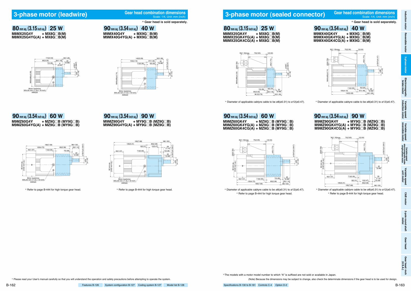
Specifications B-130 to B-161 Option D-2Controls C-4
Inductionm
otorReversible
motor
3-phasem
otorElectrom
agneticbrake
motor
Variablespeed
inductionm
otorVariable
speedreversible
motor
Variablespeed
electromagnetic
brakesingle-phase
motor
Variablespeed
unitmotor
C&Bm
otor2-pole
roundshaft
motor
Gearhead
Gearhead
-inch(U.S.A.)
3-phase motor (sealed connector)
(Note) Because the dimensions may be subject to change, also check the determinate dimensions if the gear head is to be used for design.
B-163
3-phase motor (leadwire)
* Please read your User's manual carefully so that you will understand the operation and safety precautions before attempting to operate the system.
B-162 Model list B-128Coding system B-127System configuration B-127Features B-126
+ MX8G B(M)+ MX8G B(M)
M8MX25G4YM8MX25G4YG(A)
115(4.53)85(3.35)
7(0.28)
ø10h
7(ø
0.39
h7)
ø30
(ø1.
18)
30(1.18)32(1.26)
25(0.98)6
(0.24)
Motor leadwires300±30 mm (11.8±1.18 inch)
AWG20
MAX
ø86(
ø3.3
9)
+ MX9G B(M)+ MX9G B(M)
M9MX40G4YM9MX40G4YG(A)
142(5.59)105(4.13)
7.5(0.30)
Motor leadwires300±30 mm (11.8±1.18 inch)
AWG20
MAX
ø95(
ø3.7
4)
ø12h
7(ø0
.47)
ø36
(ø1.
42)
37(1.46)32(1.26)
25(0.98)5(0.20)
+ MZ9G B (MY9G B)+ MZ9G B (MY9G B)
M9MZ60G4YM9MZ60G4YG(A)
180(7.09)120(4.72)
7.5(0.30)40(1.57)
Motor leadwires300±30 mm (11.8±1.18 inch)
AWG20
92 m
m s
q.(3
.62
inch
sq.
)
ø15h
7(ø0
.59h
7)ø3
4(ø
1.34
)
29(1.14)
25(0.98)
7(0.28)
60(2.36)38(1.50)
+ MY9G B (MZ9G B)+ MY9G B (MZ9G B)
M9MZ90G4YM9MZ90G4YG(A)
195(7.68)135(5.31)
7.5(0.30)40(1.57)
92 m
m s
q.(3
.62
inch
sq.
)
Motor leadwires300±30 mm (11.8±1.18 inch)
AWG20
ø34
(ø1.
34)
ø15h
7(ø0
.59h
7)
60(2.36)38(1.50)
7(0.28)
29(1.14)
12(0.47)8(0.31)
25(0.98)
+ MX8G B(M)+ MX8G B(M)+ MX8G B(M)
M8MX25GK4YM8MX25GK4YG(A)M8MX25GK4CG(A)
96.3(3.79)85(3.35)
75(2.95) 1(0.04)30(1.18)max.
7(0.28)
MAX
ø86(
ø3.3
9)(2
0(0.
79))
(45(
1.77
))
ø10h
7(ø
0.39
h7)
ø30
(ø1.
18)
30(1.18)32(1.26)
25(0.98)
6(0.24)
+ MX9G B(M)+ MX9G B(M)+ MX9G B(M)
M9MX40GK4YM9MX40GK4YG(A)M9MX40GK4CG(A)
(45(
1.77
))
142(5.59)105(4.13)
7.5(0.30)
75(2.95) 1(0.04)30(1.18)max.
MAX
ø95(
ø3.7
4)(2
0(0.
79))
ø12h
7(ø0
.47)
ø36
(ø1.
42)
37(1.46)32(1.26)
25(0.98)
5(0.20)
+ MZ9G B (MY9G B)+ MZ9G B (MY9G B)+ MZ9G B (MY9G B)
M9MZ60GK4YM9MZ60GK4YG(A)M9MZ60GK4CG(A)
75(2.95) 1(0.04)30(1.18)max.
180(7.09)120(4.72)
7.5(0.30)40(1.57)
92 m
m s
q.(3
.62
inch
sq.
)
(45(
1.77
))
(20(
0.79
))
ø15h
7(ø0
.59h
7)ø3
4(ø
1.34
)
29(1.14)
25(0.98)7(0.28)
60(2.36)38(1.50)
* Diameter of applicable cabtyre cable to be ø8(ø0.31) to ø12(ø0.47).* Refer to page B-444 for high torque gear head.
* Refer to page B-444 for high torque gear head. * Refer to page B-444 for high torque gear head.
* Diameter of applicable cabtyre cable to be ø8(ø0.31) to ø12(ø0.47). * Diameter of applicable cabtyre cable to be ø8(ø0.31) to ø12(ø0.47).
+ MY9G B (MZ9G B)+ MY9G B (MZ9G B)+ MY9G B (MZ9G B)
M9MZ90GK4YM9MZ90GK4YG(A)M9MZ90GK4CG(A)
75(2.95) 1(0.04)30(1.18)max.
195(7.68)135(5.31)
40(1.57)
92 m
m s
q.(3
.62
inch
sq.
)
(45(
1.77
))
(20(
0.79
))
ø34
(ø1.3
4)
ø15h
7(ø0
.59h
7)
60(2.36)38(1.50)
7(0.28)
29(1.14)
12(0.47)8(0.31)
25(0.98)
7.5(0.30)
* Diameter of applicable cabtyre cable to be ø8(ø0.31) to ø12(ø0.47).* Refer to page B-444 for high torque gear head.
Gear head combination dimensionsScale: 1/4, Unit: mm (inch)
Gear head combination dimensionsScale: 1/4, Unit: mm (inch)
*The models with a motor model number to which “A” is suffixed are not sold or available in Japan.
80 mm sq. (3.15 inch sq.) 25 W
90 mm sq. (3.54 inch sq.) 60 W
90 mm sq. (3.54 inch sq.) 40 W
90 mm sq. (3.54 inch sq.) 90 W
80 mm sq. (3.15 inch sq.) 25 W
90 mm sq. (3.54 inch sq.) 60 W
90 mm sq. (3.54 inch sq.) 40 W
90 mm sq. (3.54 inch sq.) 90 W
* Gear head is sold separately. * Gear head is sold separately.
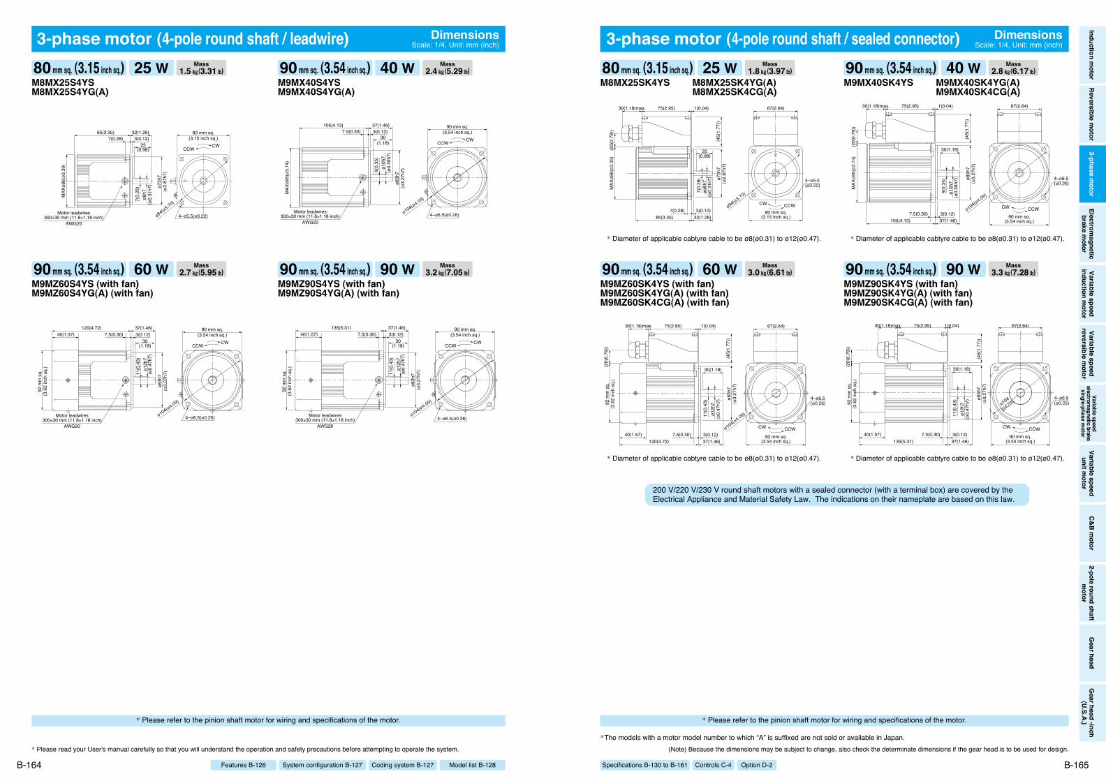
Specifications B-130 to B-161 Option D-2Controls C-4
Inductionm
otorReversible
motor
3-phasem
otorElectrom
agneticbrake
motor
Variablespeed
inductionm
otorVariable
speedreversible
motor
Variablespeed
electromagnetic
brakesingle-phase
motor
Variablespeed
unitmotor
C&Bm
otor2-pole
roundshaft
motor
Gearhead
Gearhead
-inch(U.S.A.)
(Note) Because the dimensions may be subject to change, also check the determinate dimensions if the gear head is to be used for design.
B-165
3-phase motor (4-pole round shaft / leadwire)
* Please read your User's manual carefully so that you will understand the operation and safety precautions before attempting to operate the system.
B-164 Model list B-128Coding system B-127System configuration B-127Features B-126
M8MX25S4YSM8MX25S4YG(A)
Motor leadwires300±30 mm (11.8±1.18 inch)
AWG20
ø73h
7(ø
2.87
h7)
MAX
ø86(
ø3.3
9)
85(3.35) 32(1.26)7(0.28) 3(0.12)
80 mm sq.(3.15 inch sq.)
CWCCW25
(0.98)ø8
h7(ø
0.31
h7)
7(0.
28)
ø94(ø3.70)
4–ø5.5(ø0.22)
M9MX40S4YSM9MX40S4YG(A)
105(4.13) 37(1.46)7.5(0.30) 3(0.12)
ø83h
7(ø
3.27
h7)
90 mm sq.(3.54 inch sq.)
CWCCW
Motor leadwires300±30 mm (11.8±1.18 inch)
AWG20
30(1.18)
ø10h
7(ø
0.39
h7)
9(0.
35)
MAX
ø95(
ø3.7
4)
4–ø6.5(ø0.26)ø104(ø4.09)
M9MZ60S4YS (with fan)M9MZ60S4YG(A) (with fan)
120(4.72) 37(1.46)7.5(0.30)40(1.57) 3(0.12)
ø83h
7(ø
3.27
h7)
90 mm sq.(3.54 inch sq.)
CWCCW
Motor leadwires300±30 mm (11.8±1.18 inch)
AWG20
92 m
m s
q.(3
.62
inch
sq.
)
30(1.18)
ø12h
7(ø
0.47
h7)
11(0
.43)
4–ø6.5(ø0.26)ø104(ø4.09)
M9MZ90S4YS (with fan)M9MZ90S4YG(A) (with fan)
4–ø6.5(ø0.26)
CWCCW
92 m
m s
q.(3
.62
inch
sq.
)
Motor leadwires300±30 mm (11.8±1.18 inch)
AWG20
90 mm sq.(3.54 inch sq.)
135(5.31) 37(1.46)7.5(0.30)40(1.57) 3(0.12)
ø83h
7(ø
3.27
h7)
30(1.18)
ø12h
7(ø
0.47
h7)
11(0
.43)
ø104(ø4.09)
M9MZ60SK4YS (with fan)M9MZ60SK4YG(A) (with fan)M9MZ60SK4CG(A) (with fan)
75(2.95) 1(0.04)30(1.18)max.
CCWCW
67(2.64)
120(4.72) 37(1.46)7.5(0.30)40(1.57) 3(0.12)
ø83h
7(ø
3.27
h7)
92 m
m s
q.(3
.62
inch
sq.
)
30(1.18)
ø12h
7(ø
0.47
h7)
11(0
.43)
(45(
1.77
))
(20(
0.79
))
4–ø6.5(ø0.26)
90 mm sq.(3.54 inch sq.)
ø104(ø4.09)
M9MZ90SK4YS (with fan)M9MZ90SK4YG(A) (with fan)M9MZ90SK4CG(A) (with fan)
90 mm sq.(3.54 inch sq.)
ø104
(ø4.09)
75(2.95) 1(0.04)30(1.18)max.
CCWCW
67(2.64)
135(5.31) 37(1.46)7.5(0.30)40(1.57) 3(0.12)
ø83h
7(ø
3.27
h7)
92 m
m s
q.(3
.62
inch
sq.
)
30(1.18)
ø12h
7(ø
0.47
h7)
11(0
.43)
(45(
1.77
))
(20(
0.79
))
4–ø6.5(ø0.26)
M8MX25SK4YS M8MX25SK4YG(A)M8MX25SK4CG(A)
85(3.35)
75(2.95) 1(0.04)30(1.18)max.
32(1.26)7(0.28) 3(0.12)
ø73h
7(ø
2.87
h7)
4–ø5.5(ø0.22)
CCWCW
67(2.64)
25(0.98)
øø8h
7(ø
0.31
h7)
7(0.
28)
MAX
ø86(
ø3.3
9)
(45(
1.77
))
(20(
0.79
))
80 mm sq.(3.15 inch sq.)
ø94(ø3.70)
M9MX40SK4YS M9MX40SK4YG(A)M9MX40SK4CG(A)
ø83h
7(ø
3.27
h7)
105(4.13) 37(1.46)7.5(0.30) 3(0.12)
75(2.95) 1(0.04)30(1.18)max.
CCWCW
67(2.64)
30(1.18)
ø10h
7(ø
0.39
h7)
9(0.
35)
(45(
1.77
))
(20(
0.79
))M
AXø9
5(ø3
.74)
4–ø6.5(ø0.26)
90 mm sq.(3.54 inch sq.)
ø104(ø4.09)
3-phase motor (4-pole round shaft / sealed connector) DimensionsScale: 1/4, Unit: mm (inch)
DimensionsScale: 1/4, Unit: mm (inch)
* Diameter of applicable cabtyre cable to be ø8(ø0.31) to ø12(ø0.47). * Diameter of applicable cabtyre cable to be ø8(ø0.31) to ø12(ø0.47).
* Diameter of applicable cabtyre cable to be ø8(ø0.31) to ø12(ø0.47). * Diameter of applicable cabtyre cable to be ø8(ø0.31) to ø12(ø0.47).
200 V/220 V/230 V round shaft motors with a sealed connector (with a terminal box) are covered by the Electrical Appliance and Material Safety Law. The indications on their nameplate are based on this law.
*The models with a motor model number to which “A” is suffixed are not sold or available in Japan.
Mass1.5 k"(3.31 lb)80 mm sq. (3.15 inch sq.) 25 W Mass
2.4 k"(5.29 lb)90 mm sq. (3.54 inch sq.) 40 W
Mass2.7 k"(5.95 lb)90 mm sq. (3.54 inch sq.) 60 W Mass
3.2 k"(7.05 lb)90 mm sq. (3.54 inch sq.) 90 W
Mass1.8 k"(3.97 lb)80 mm sq. (3.15 inch sq.) 25 W Mass
2.8 k"(6.17 lb)90 mm sq. (3.54 inch sq.) 40 W
Mass3.0 k"(6.61 lb)90 mm sq. (3.54 inch sq.) 60 W Mass
3.3 k"(7.28 lb)90 mm sq. (3.54 inch sq.) 90 W
* Please refer to the pinion shaft motor for wiring and specifications of the motor.* Please refer to the pinion shaft motor for wiring and specifications of the motor.