Embed Size (px)
Citation preview
Reversi: Post-Silicon Validation System for Modern MicroprocessorsIlya Wagner and Valeria Bertacco
University of Michigan{iwagner, valeria}@umich.edu
Abstract— Verification remains an integral and crucial phaseof today’s microprocessor design and manufacturing process.Unfortunately, with soaring design complexities and decreasingtime-to-market windows, today’s verification approaches areincapable of fully validating a microprocessor before its releaseto the public. Increasingly, post-silicon validation is deployed todetect complex functional bugs in addition to exposing electricaland manufacturing defects. This is due to the significantlyhigher execution performance offered by post-silicon methods,compared to pre-silicon approaches. Validation in the post-silicon domain is predominantly carried out by executingconstrained-random test instruction sequences directly on ahardware prototype. However, to identify errors, the stateobtained from executing tests directly in hardware must becompared to the one produced by an architectural simulationof the design’s golden model. Therefore, the speed of validationis severely limited by the necessity of a costly simulation step.
In this work we address this bottleneck in the traditionalflow and present a novel solution for post-silicon validation thatexposes its native high performance. Our framework, calledReversi, generates random programs in such a way that theircorrect final state is known at generation time, eliminating theneed for architectural simulations. Our experiments show thatReversi generates tests exposing more bugs faster, and can speedup post-silicon validation by 20x compared to traditional flows.
I. INTRODUCTION
Verification remains an unavoidable, yet quite challengingand time-consuming aspect of the microprocessor design andfabrication process. With shortening product timelines andincreasing time-to-market pressure, processor manufacturinghouses are forced to pour more and more resources intoverification. The problem is exacerbated by the appearanceand growing adoption of multi-core chips. The design effortin these systems is lower than that of a single-core chip of asimilar size, since cores are replicated from a single design.The verification effort is however, higher, because in additionto validating the cores, inter-core communication must alsobe verified. Therefore, with processor complexity increasingrapidly, and verification speeds lagging behind, bugs, suchas the AMD Opteron REP MOVS error [2] and functionalproblems in the Intel’s Core 2 Duo [3, 4], continue to slipinto production silicon.
Hardware verification can be divided into two phases: pre-and post-silicon. Pre-silicon verification employs two majorfamilies of solutions: simulation-based tools and formaltechniques. Although formal solutions can be used to provekey design properties, such as absence of deadlock, properALU and FPU functionality, etc., they suffer from the stateexplosion problem and can ultimately be used only on smalldesign modules. For example, in the verification of the IntelPentium 4 processor, formal methods were used only onfloating-point units, schedulers and instruction decoders [8].Simulation approaches, on the other hand, do not have suchstrict limitations, but neither can provide hard guarantees of
correctness: only those behaviors that have occurred duringthe simulation can be validated. Nevertheless, simulationremains the method of choice for pre-silicon verification dueto its scalability.
Post-silicon validation relies on a concept similar to sim-ulation: the hardware prototype executes as many randomlygenerated input vectors as possible. However, there are a fewkey differences between this approach and pre-silicon valida-tion. First, the execution on a hardware prototype is severalorders of magnitude faster than any functional simulator,therefore, significantly more test vectors can be checked.However, this high speed comes at the price of limitedobservability: the internal state of the prototype cannot beeasily or fully observed, forcing the engineers to diagnoseerrors from the architectural state of the system. Tests inthe post-silicon domain consists of directed tests checkingspecific features of the processor, compatibility checks, suchas operating system boot-up and tests with legacy software,as well as automatically generated random tests [8, 16]. Dueto the unpredictable outcome of these random programs,engineers must simulate them on a known-correct model ofthe design to obtain the correct final state of the hardwareprototype to identify discrepancies, potentially revealing abug. While tests can be run at-speed on the hardware, testgeneration and simulation constitute the bottleneck in thisprocess, limiting it to the performance level of pre-siliconsimulation. Consequently, design houses are forced to spendenormous computational resources on test generation andsimulation servers [16].
Traditional post-silicon testing solutions differ from vali-dation in that they rely on a structural model of the design todetermine the correct behavior of the silicon part under testand detect electrical and manufacturing defects. However,functional errors in the design will be present in both thehardware prototype and the structural model generated fromRTL, thus testing is not viable to find this kind of bugs.
In this paper we take the first step towards a novelhigh-throughput post-silicon validation methodology, whichallows for test generation to match the performance of execu-tion of the silicon prototype. By cleverly crafting randomizedtests with known final outcome, we address the bottleneckof the traditional post-silicon flow, while leveraging its highdesign coverage.
A. Contributions of This Work
The main contribution of this paper is the development ofa novel test generation framework, called Reversi, for post-silicon processor validation. Our goal is to exploit the fullperformance potential of silicon prototypes and eliminate thecostly simulation step required to obtain a known-correctfinal state. To this end, tests are generated by Reversi in such
a way that at the end of the execution, the initial state of themachine is restored. Therefore, the final state of such a re-versible program is known a priori and, the simulation phaseof the validation process is bypassed. Since our programgeneration algorithm is agnostic to any particular instructionset, it can be easily ported between processors with differentinstruction and feature sets. Moreover, the absence of thesimulation step in our framework allows for tests to begenerated directly by hardware residing on the same systemboard as the prototype, eliminating the need for costly testgeneration servers. Consequently, validation speed becomesonly limited by the speed of communication between theprototype and the testing board. Moreover, once the systemunder test is sufficiently validated, the test generator can rundirectly on it. In this latter case, tests can be produced inone portion of the chip’s cores and transferred to other coresfor execution. If the generator cores were flawed, they wouldnot produce proper reversible programs, exposing the issue.
We evaluated our framework against a traditional post-silicon validation flow based on a constrained-random testgenerator paired with an architectural simulator. Our ex-perimental results demonstrate that reversible programs canexpose more complex processor bugs faster than traditionalmethods and, at the same time, boost the performance of thetesting process by 20x.
The remainder of this paper is organized as follows.Section II reviews prior work in post-silicon validation withrandom instruction generators. Sections III and IV presentthe Reversi solution and detail the construction of complexprogram structures. Section V provides a comparative evalu-ation of our approach, while Section VI concludes the paper.
II. PRIOR WORK
Hardware verification with constrained-random test gen-eration has been a focus of both academic and industrialresearch for a long time. Most efforts, however, have beendedicated to the pre-silicon verification domain, where testlength is relatively short compared to real-life applications.One of the most prominent industry tools in this familyis Genesys-Pro [7] developed by IBM. This tool providesadvanced capabilities for test generation (biasing primitives,templated specification language, etc.) However, it is de-signed primarily as a pre-silicon tool. Genesys is not capableof producing tests with known final states, and hence itsuse in the context of post-silicon validation would requirea simulator to compute such states. Several other industrialsolutions [1, 14] provide similar features, but again requirea simulator to generate the final processor state.
As reported by Rotithor in [16], test generation enginestargeting the post-silicon domain share some of their prop-erties with the tools mentioned above: test scenarios have atemplated format allowing for fast generation of randomizedprograms. Note however, that the setup described in [16]calls for a number of servers to build the tests and known-correct design models to simulate these tests and obtain thecorrect final state, which will be compared with the resultsof the prototype execution. Therefore, the framework in [16]
still requires a simulation-based checker in order to exposebugs, unless they manifest themselves more explicitly, e.g.,as a deadlock or early test termination.
There also exists a variety of testing solutions that combineATPG (automatic test patter generation) [11] with techniquesfor silicon state acquisition such as scan [13], JTAG [12],cycle breakpoint [9] or on-chip-logic analyzers [10]. Un-fortunately, ATPG approaches are only capable of exposingelectrical and manufacturing defects. A functional error, onthe other hand, cannot be flagged by these solutions, sinceit is present not only in the hardware under test, but in thestructural model used by the test generator as well. Unlikethese approaches, our solution relies on a functional, high-level specification of the hardware to expose design defects.
Finally, Raina and Molyneaux presented in [15] a solutionbased on the use of instructions and their inverses for proces-sor verification. However, their work used the reversibilityscheme for cache verification, rather than for processor cores.
III. REVERSI TEST GENERATION SYSTEM
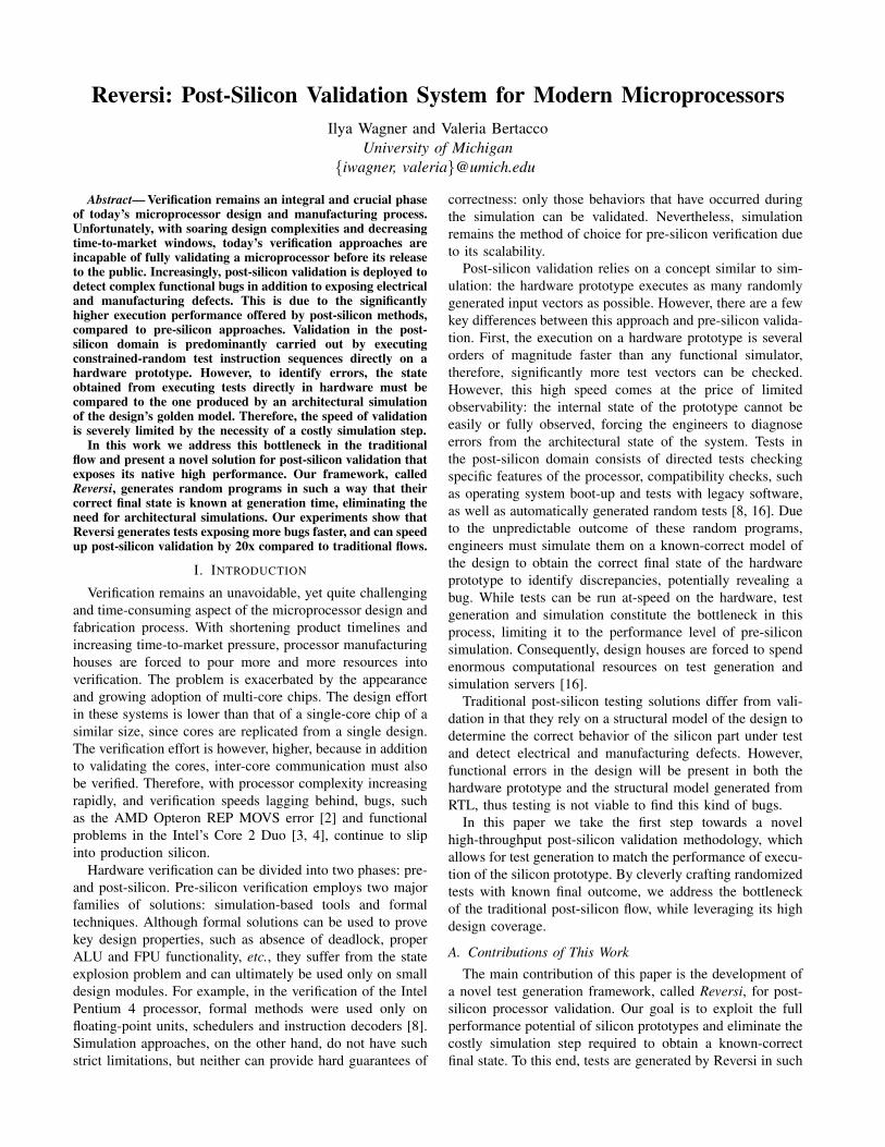
Typically post-silicon functional validation in industryhas been conducted with two types of tests: parameterizeddirected tests and constrained-random (or pseudo-random)tests. Although the former ones can provide high coverage,they require significant human effort to be developed. Thepseudo-random tests, constrained to produce only valid in-struction sequences, can be generated automatically, howeveroften suffer from lower coverage. More importantly, the finalstate of the processor after executing a random test sequenceis unknown. Therefore, engineers must resort to simulatingthe design’s golden model to compute the final processorstate and check it against state dumps of the actual hardwareprototype (as illustrated in Figure 1.a).
Reversi
Silicon
prototype
=
Random Generator
=
Simulatorfinal state
Constr.Random program
Critical path
Critical path
a.
Architect.
simulationSilicon
prototype
Randomreversible program
Hardware prototype
Hardware prototype
Ho
st m
ach
ine
Prototypefinal state
Final state
Initialstate
b.Fig. 1. A typical post-silicon validation flow vs. a Reversi-based flow. a.In a typical post-silicon methodology, random tests are produced by a testgenerator and fed to both a golden model simulator and a silicon prototype.Bugs are flagged by differences between the prototype’s and simulator’s finalstates. Both test generation and simulation are done on a host machine atrelatively slow speed. b. A Reversi-based flow does not require a simulator:random reversible programs can be generated on a tester board or on thehardware prototype itself. Bugs are flagged by differences between final andinitial states of the prototype.
Unfortunately, as was mentioned above, the simulation ofthe golden model is several orders of magnitude slower thanthe hardware execution, therefore, the computation of the
final state becomes a bottleneck for the entire effort. Weaddress this issue in our methodology by developing a post-silicon solution which fully exploits the performance of thehardware under test. We designed a test generator, calledReversi, that produces tests whose outcome is known byconstruction. This allows us to bypass the simulation stepand speed up the overall validation flow (Figure 1.b).
The main observation that we made in developing Reversiis that many instructions in a processor’s ISA have counter-parts, i.e., operations whose functionality is the inverse ofthe former, such as restoring a value in a particular register,clearing a set of flags, etc. Moreover, if no single instructionexists to reverse the action of another, one can devise a smallprogram sequence to be used to the same effect. This wasthe case, for example, for the integer multiply instruction inone of the ISAs that we used in our experimental evaluation.No instruction for integer division was implemented, but wecould resort to software emulation of division to revert theeffect of multiplication. Note that, if the emulation routineexposed any error in the hardware prototype, the result of themultiplication would not be reversed correctly. The presenceof inverse functions enables us to design programs thatinclude every instruction in an ISA, and for which the finalregister values match exactly the initial ones. In other terms,if x is a vector representing the processor state, and eachFi / F−1
i pair represents a distinct function (either an ISAinstruction or an instruction block) and the correspondinginverse, then a program generated by Reversi applies thefollowing sequence of functions to the state x:
x = F−11 (F−1
2 (...(F−1n (Fn(...(F2(F1(x)..) (1)
A. Reversible and Non-reversible Instructions
In order to create reversible programs, we first analyzeeach ISA and identify inverse instructions (or instructionsequences) for each of the operations. By applying theseoperations in the manner discussed above we can modifythe state of the processor and then properly restore it (inthe absence of bugs). This allows us to create a blockdatabase containing pairs of functional blocks: for eachoperation block, there is a corresponding inverse block. Eachblock contains either a single instruction or a small programsequence. An operation block modifies the value of a register,called the focus register, while its inverse restores its initialvalue. The ID of the focus register for each block is aparameter set by Reversi dynamically during test generation.Therefore, the same block may appear in the test programmultiple times, each time modifying a different register,which allows a varied set of programs to be created. Notethat blocks operate only on a single focus register at a time tomaintain the reversibility of our program and track the cor-rectness of its execution. Thus, for instructions with multipleoperands, only one of the registers is the focus register, whileother operands are randomly generated by Reversi accordingto the instruction format. The flexible and robust structureof the block database allows the Reversi algorithm to beagnostic to the functionality of individual blocks and the
TABLE I- Reversi blocks for arithmetic and logic instructions
Instruction Operation Block Inverse Blockadd add subsub sub addinc inc decdec dec incxor xor and/or emulated xornot not nand emulated notneg neg -1 mult emulated negand and/or emulated xor xoror and/or emulated xor xormult mult emulated divisionrol rol rorror ror rolsll store lost bits, sll srl, restore lost bitssrl store lost bits, srl sll, restore lost bitssra 1.store lost bits, 1.rol
2.create mask 2.apply mask3.sra 3.restore lost bits
underlying ISA, making our framework readily adaptable todifferent processor architectures. Moreover, since blocks inReversi may contain multiple instructions, we can populatethe database with complex functions, including loops, pro-cedure calls, etc., and create elaborate tests representativeof real software. In the remainder of the section we discussindividual classes of instructions and implementation detailsof operation and inverse block verifying them.Arithmetic and logic instructions. The design of blockscontaining arithmetic and logic instructions is summarizedin Table I and is fairly straightforward, since the majorityof these operations have a simple inverse directly in theISA. For example, add can be reversed by sub, inc bydec, ror (rotate right) by rol (rotate left) and so on. If aninstruction does not have a counterpart in the ISA, a smallroutine can be used to emulate its inverse. Some Booleanlogic instructions, such as and and or, do not have directinverses, however, these operations can be used to constructan xor logic function, which can then be reversed by an xorinstruction. Such structure is also beneficial for verificationof the xor instruction itself, since operation and inverse blockin this case exercise different hardware modules. Situationswhere the same processor modules are used in the functionand its inverse should be avoided to prevent bugs beingmasked by faulty hardware.
Some ISA operations, for example sll and srl cause someof the data bits to be lost. In order to be able to restore fullythe initial value of the focus register, we must mask out thesebits and store them in the scratchpad memory before applyingthe operation. When the program reaches the inverse block,it first applies the reverse operation (i.e., shift in the oppositedirection in this case) and then loads and restores the bitsfrom memory. Finally, the outcome of an instruction maydepend on the sign or value of the focus register, which is notknown at generation time. For example, shift-arithmetic right(sra) will preserve the sign of the value by replicating itsmost significant bit. Blocks verifying such value-dependentoperations can be built to execute differently based on theoperand’s value, saving and restoring all the bits required todeterministically retrieve the initial data.
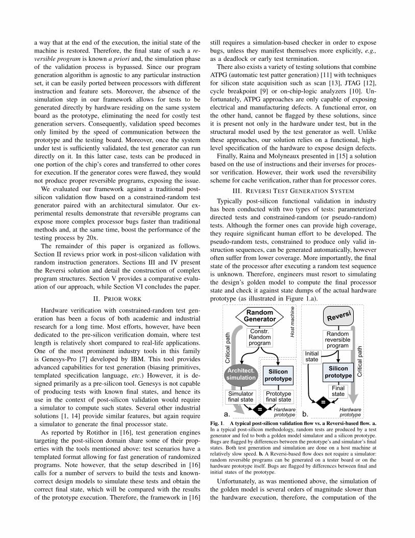
Load/store instructions. In Reversi the correctness of loadand store instructions is checked by copying a data structure:a region of memory is initialized with random values andload/store pairs are used to copy it to a new location. Wedo not require that the copy preserves the order of thebytes, rather, we treat the data structure as a pool of values,which can appear out of order at destination (see Figure2). This allows programs generated by Reversi to closelyresemble real software applications where loads bring datafrom memory to the processor, and stores copy results ofthe computation back. Moreover, because of their randomnature, Reversi programs contain a variety of cache andmemory access patterns, that can expose corner-case bugsin the memory subsystem. To check the correctness of thefinal state of the memory, we simply compare an xor-hashof the memory values before and after test execution. Thisapproach allows Reversi to expose load/store related issuessuch as illegal memory accesses and/or data corruption.
��������� �������
������� ���������
��������
������������ �������
������� ��������� ���
���
���
�������
���
Fig. 2. Blocks for load and store instructions. Load/store pairs are usedto copy bytes from source to destination data structures. Bytes may bereshuffled, but their xor-hashes must match.
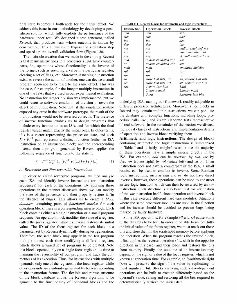
Branch instructions. The block database of Reversi alsocontains templates that test branches with different prop-erties: forward/backward, taken/nottaken etc. For example,an operation block for a forward taken branch (Figure 3.a)contains a store operation that saves the value of the focusregister to scratchpad memory, followed by a load thatoverwrites the focus register with a predetermined constantand then by the branch itself. Although the constant isgenerated randomly, its value is dependent on the type ofthe tested branch. For example, a template for a beq (branchif equal) instruction, overwrites the focus register with arandom constant and then loads a temporary register withthe same value to test the branch. With reference to Figure3.a, the destination of the branch is located in the inverseblock, which also contains a load operation restoring thefocus register and a return jump. Therefore, if all controlflow instructions are executed correctly, the value of thefocus register after execution of the block is preserved. If,however, the branch is not taken by a faulty hardware, thefocus register would not be restored. Note that the inverseblock is only accessible via the proper branch and is skippedotherwise. If, however, the unconditional branch in Figure 3.ais not taken due to a bug, the halt instruction is executed andthe test stops without fully reverting processor’s state. Thestructure of the blocks for forward not-taken branch (Figure3.b) is similar to the one described above differing in theposition of the restoring load. We use a similar techniqueto detect other faulty control flow operations, initializing allunused locations in the program to halt instructions.
�����
����
�������������
�� ����������
�� !�
"#�������!��$%
&�'�� �!��$%
�����������(���$)
���*��+*�#
,�$����(���$)
�����
����
�������������
�� ����������
"#�������!��$%
&�'�� �!��$%
�����������(���$)
���*��+*�#
,�$����(���$)
Fig. 3. Branch operations. a. Block pair for forward taken branch.The operation block includes a modifying load, a branch and the returnlabel, while the inverse block contains a restoring load and a return jump.b. Structure of a forward not-taken branch. The dashed line indicates theprogram flow for a case when the branch is taken by the faulty hardware.
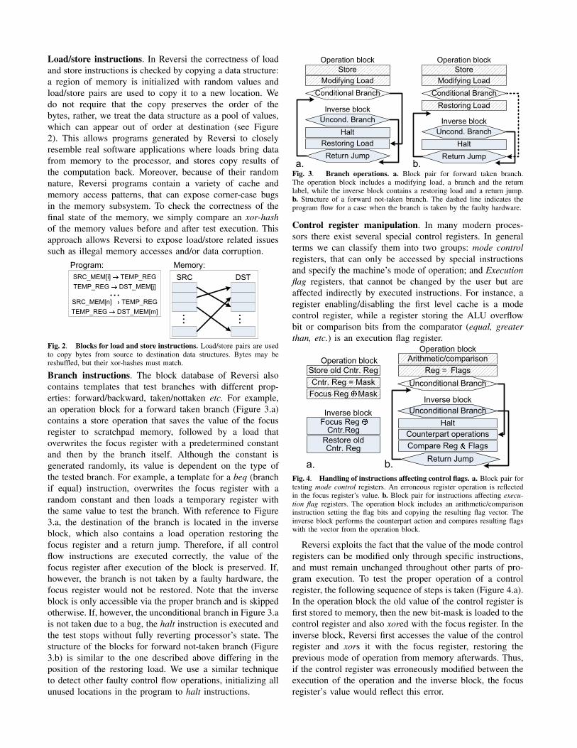
Control register manipulation. In many modern proces-sors there exist several special control registers. In generalterms we can classify them into two groups: mode controlregisters, that can only be accessed by special instructionsand specify the machine’s mode of operation; and Executionflag registers, that cannot be changed by the user but areaffected indirectly by executed instructions. For instance, aregister enabling/disabling the first level cache is a modecontrol register, while a register storing the ALU overflowbit or comparison bits from the comparator (equal, greaterthan, etc.) is an execution flag register.
����
���- .���
��*����#����#�������
/���)����$0$��#��� ��
���#������ .���
"#�������!��$%
&�'�� �!��$%
�� !�
.�$* �����������
.�$* ��� �� %
�� ���������������
����������������"#�������!��$%
&�'�� �!��$%
��������-�� %
,�$����������(���$)
,�$����������(���$)
���*��+*�#
Fig. 4. Handling of instructions affecting control flags. a. Block pair fortesting mode control registers. An erroneous register operation is reflectedin the focus register’s value. b. Block pair for instructions affecting execu-tion flag registers. The operation block includes an arithmetic/comparisoninstruction setting the flag bits and copying the resulting flag vector. Theinverse block performs the counterpart action and compares resulting flagswith the vector from the operation block.
Reversi exploits the fact that the value of the mode controlregisters can be modified only through specific instructions,and must remain unchanged throughout other parts of pro-gram execution. To test the proper operation of a controlregister, the following sequence of steps is taken (Figure 4.a).In the operation block the old value of the control register isfirst stored to memory, then the new bit-mask is loaded to thecontrol register and also xored with the focus register. In theinverse block, Reversi first accesses the value of the controlregister and xors it with the focus register, restoring theprevious mode of operation from memory afterwards. Thus,if the control register was erroneously modified between theexecution of the operation and the inverse block, the focusregister’s value would reflect this error.
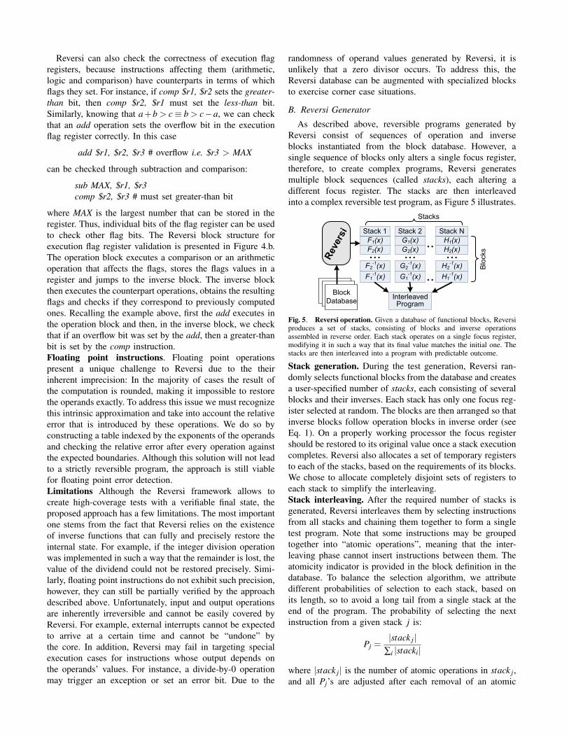
Reversi can also check the correctness of execution flagregisters, because instructions affecting them (arithmetic,logic and comparison) have counterparts in terms of whichflags they set. For instance, if comp $r1, $r2 sets the greater-than bit, then comp $r2, $r1 must set the less-than bit.Similarly, knowing that a+b > c ≡ b > c−a, we can checkthat an add operation sets the overflow bit in the executionflag register correctly. In this case
add $r1, $r2, $r3 # overflow i.e. $r3 > MAX
can be checked through subtraction and comparison:
sub MAX, $r1, $r3comp $r2, $r3 # must set greater-than bit
where MAX is the largest number that can be stored in theregister. Thus, individual bits of the flag register can be usedto check other flag bits. The Reversi block structure forexecution flag register validation is presented in Figure 4.b.The operation block executes a comparison or an arithmeticoperation that affects the flags, stores the flags values in aregister and jumps to the inverse block. The inverse blockthen executes the counterpart operations, obtains the resultingflags and checks if they correspond to previously computedones. Recalling the example above, first the add executes inthe operation block and then, in the inverse block, we checkthat if an overflow bit was set by the add, then a greater-thanbit is set by the comp instruction.Floating point instructions. Floating point operationspresent a unique challenge to Reversi due to the theirinherent imprecision: In the majority of cases the result ofthe computation is rounded, making it impossible to restorethe operands exactly. To address this issue we must recognizethis intrinsic approximation and take into account the relativeerror that is introduced by these operations. We do so byconstructing a table indexed by the exponents of the operandsand checking the relative error after every operation againstthe expected boundaries. Although this solution will not leadto a strictly reversible program, the approach is still viablefor floating point error detection.Limitations Although the Reversi framework allows tocreate high-coverage tests with a verifiable final state, theproposed approach has a few limitations. The most importantone stems from the fact that Reversi relies on the existenceof inverse functions that can fully and precisely restore theinternal state. For example, if the integer division operationwas implemented in such a way that the remainder is lost, thevalue of the dividend could not be restored precisely. Simi-larly, floating point instructions do not exhibit such precision,however, they can still be partially verified by the approachdescribed above. Unfortunately, input and output operationsare inherently irreversible and cannot be easily covered byReversi. For example, external interrupts cannot be expectedto arrive at a certain time and cannot be “undone” bythe core. In addition, Reversi may fail in targeting specialexecution cases for instructions whose output depends onthe operands’ values. For instance, a divide-by-0 operationmay trigger an exception or set an error bit. Due to the
randomness of operand values generated by Reversi, it isunlikely that a zero divisor occurs. To address this, theReversi database can be augmented with specialized blocksto exercise corner case situations.
B. Reversi Generator
As described above, reversible programs generated byReversi consist of sequences of operation and inverseblocks instantiated from the block database. However, asingle sequence of blocks only alters a single focus register,therefore, to create complex programs, Reversi generatesmultiple block sequences (called stacks), each altering adifferent focus register. The stacks are then interleavedinto a complex reversible test program, as Figure 5 illustrates.
�121345 �1
21345 �121345
�621345 �6
21345 �621345
��� ��� ����1345 �1345 �1345
�6345 �6345 �6345
������� ������ ������
��
��
��� �� �� ��������
������
���
���
�����
�������
������
�
Fig. 5. Reversi operation. Given a database of functional blocks, Reversiproduces a set of stacks, consisting of blocks and inverse operationsassembled in reverse order. Each stack operates on a single focus register,modifying it in such a way that its final value matches the initial one. Thestacks are then interleaved into a program with predictable outcome.
Stack generation. During the test generation, Reversi ran-domly selects functional blocks from the database and createsa user-specified number of stacks, each consisting of severalblocks and their inverses. Each stack has only one focus reg-ister selected at random. The blocks are then arranged so thatinverse blocks follow operation blocks in inverse order (seeEq. 1). On a properly working processor the focus registershould be restored to its original value once a stack executioncompletes. Reversi also allocates a set of temporary registersto each of the stacks, based on the requirements of its blocks.We chose to allocate completely disjoint sets of registers toeach stack to simplify the interleaving.Stack interleaving. After the required number of stacks isgenerated, Reversi interleaves them by selecting instructionsfrom all stacks and chaining them together to form a singletest program. Note that some instructions may be groupedtogether into “atomic operations”, meaning that the inter-leaving phase cannot insert instructions between them. Theatomicity indicator is provided in the block definition in thedatabase. To balance the selection algorithm, we attributedifferent probabilities of selection to each stack, based onits length, so to avoid a long tail from a single stack at theend of the program. The probability of selecting the nextinstruction from a given stack j is:
Pj =|stack j|
∑i |stacki|where |stack j| is the number of atomic operations in stack j,and all Pj’s are adjusted after each removal of an atomic
operation. Note that the requirements of using disjoint setsof registers in each stack limits the total number of stacksthat we can have in Reversi. We chose to forego more com-plex dynamic register set partitioning (as in some compilertechniques) in favor of faster test generation.
The test program includes one last routine that calculatesthe final xor-hash of the destination memory data structure.When the program terminates the final values of the focusregisters and the hash of the destination memory are com-pared to the initial state computed by Reversi during the gen-eration to determine if the test executed successfully. It is alsoimportant to note that Reversi programs can provide more aidin debugging than traditional randomly generated programs.If the test results indicate that there is a bug in the processor,a validation engineer can quickly check if the exposinginstruction sequence is located in an individual stack, by re-running the program without interleaving. Insights into thenature of the bug can also be found by “peeling” operationand inverse blocks from the program. Therefore, a reversibleprogram exposing a bug can be dramatically shortened toalleviate debugging. In contrast, in a traditional flow a costlyre-simulation is required to obtain the new golden state aftereach change of the test program.
IV. EXAMPLE
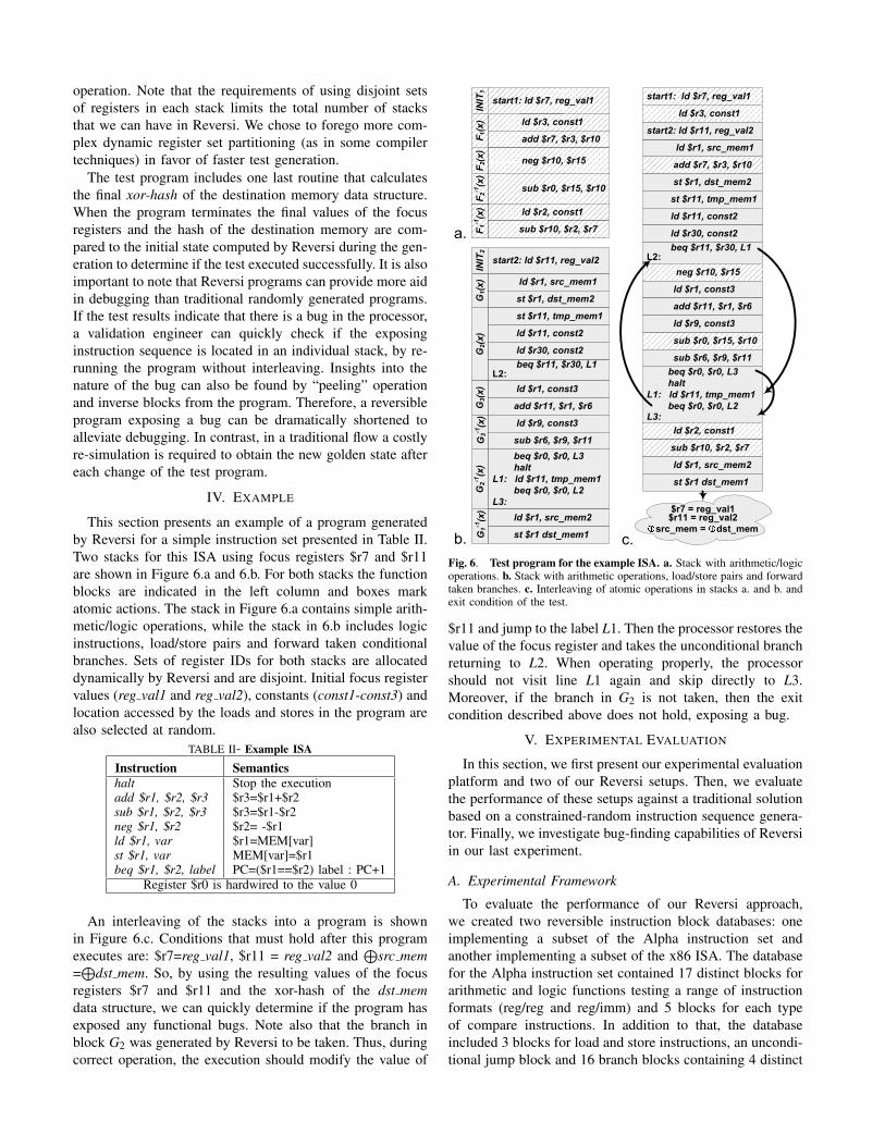
This section presents an example of a program generatedby Reversi for a simple instruction set presented in Table II.Two stacks for this ISA using focus registers $r7 and $r11are shown in Figure 6.a and 6.b. For both stacks the functionblocks are indicated in the left column and boxes markatomic actions. The stack in Figure 6.a contains simple arith-metic/logic operations, while the stack in 6.b includes logicinstructions, load/store pairs and forward taken conditionalbranches. Sets of register IDs for both stacks are allocateddynamically by Reversi and are disjoint. Initial focus registervalues (reg val1 and reg val2), constants (const1-const3) andlocation accessed by the loads and stores in the program arealso selected at random.
TABLE II- Example ISA
Instruction Semanticshalt Stop the executionadd $r1, $r2, $r3 $r3=$r1+$r2sub $r1, $r2, $r3 $r3=$r1-$r2neg $r1, $r2 $r2= -$r1ld $r1, var $r1=MEM[var]st $r1, var MEM[var]=$r1beq $r1, $r2, label PC=($r1==$r2) label : PC+1
Register $r0 is hardwired to the value 0
An interleaving of the stacks into a program is shownin Figure 6.c. Conditions that must hold after this programexecutes are: $r7=reg val1, $r11 = reg val2 and
⊕src mem
=⊕
dst mem. So, by using the resulting values of the focusregisters $r7 and $r11 and the xor-hash of the dst memdata structure, we can quickly determine if the program hasexposed any functional bugs. Note also that the branch inblock G2 was generated by Reversi to be taken. Thus, duringcorrect operation, the execution should modify the value of
��78���98�:;9�����
��78�;98�;9�:���� ��8���9����������78�;98�;9���:
��
������������������������ �8:9�� ���
�8<98:98�;
��8�;98�=
���8;98�=98�;
�8�9�� ���
���8�;98�98<
�������8<9�������
�������
�������
�����
����� �8�9�������
��8�9�������
��8��9��������
��78;98;9�:��������8��9����������78;98;9���:�
�������8��9�������
��78��98:;9�����
�:��� �8�9�� ��:
�8��98�98>
�:�����
�8?9�� ��:
���8>98?98��
�8�9�������
��8��������
�8:9�� ���
�8<98:98�;
��8�;98�=
���8;98�=98�;
�8�9�� ���
���8�;98�98<
�������8<9�������
�8�9�������
�������8��9�������
��8�9�������
��8��9��������
�8�9�� ��:
�8��98�98>
�8?9�� ��:
���8>98?98��
�8�9�������
��8��������
��������� ������������ ��
��������� ������
��
��
�@���
�@���
�8��9�� ���
�8:;9�� ���
�8��9�� ���
�8:;9�� ���
Fig. 6. Test program for the example ISA. a. Stack with arithmetic/logicoperations. b. Stack with arithmetic operations, load/store pairs and forwardtaken branches. c. Interleaving of atomic operations in stacks a. and b. andexit condition of the test.
$r11 and jump to the label L1. Then the processor restores thevalue of the focus register and takes the unconditional branchreturning to L2. When operating properly, the processorshould not visit line L1 again and skip directly to L3.Moreover, if the branch in G2 is not taken, then the exitcondition described above does not hold, exposing a bug.
V. EXPERIMENTAL EVALUATION
In this section, we first present our experimental evaluationplatform and two of our Reversi setups. Then, we evaluatethe performance of these setups against a traditional solutionbased on a constrained-random instruction sequence genera-tor. Finally, we investigate bug-finding capabilities of Reversiin our last experiment.
A. Experimental Framework
To evaluate the performance of our Reversi approach,we created two reversible instruction block databases: oneimplementing a subset of the Alpha instruction set andanother implementing a subset of the x86 ISA. The databasefor the Alpha instruction set contained 17 distinct blocks forarithmetic and logic functions testing a range of instructionformats (reg/reg and reg/imm) and 5 blocks for each typeof compare instructions. In addition to that, the databaseincluded 3 blocks for load and store instructions, an uncondi-tional jump block and 16 branch blocks containing 4 distinct
branching instructions, each in four possible modes (fw/bwand taken/nottaken). Similarly, the x86 block database con-tained 32 logic-arithmetic blocks testing multiple instructionformats (reg/reg, reg/imm, reg/ mem, mem/reg), 3 load-storeblocks, 1 compare block and 40 branch blocks. Reversi itselfis implemented as an optimized program in C that createdand interleaved a specified number of stacks and containedroutines to set a random initial state and perform the finalcheck. The blocks are partially pre-assembled in binary, andReversi is responsible for setting the appropriate bit-fieldswith register IDs, randomly generated constants, etc.
To compare Reversi with a traditional post-silicon val-idation flow (Figure 1.a), we created an assembly-levelconstrained-random test generator. In addition, for the archi-tectural simulation phase of the traditional post-silicon flowwe used M5 2.0b3 [5] and Bochs-2.3.5 [6] for Alpha and x86systems, respectively. Test generation and simulation for bothReversi and the traditional post-silicon flow was performedon a 3.2GHz Pentium 4 machine with 2GB of memory.
1
10
100
1000
10000
100000
K 10K 20K 30K 40K 50K 60K 70K 80K 90K 100
K
110
K
Pre-silicon simulation
Traditional Post-Si
Reversi
Tota
l tim
e (
ms)
Dynamic instructions
0K 10K 20K 30K 40K 50K 60K 70K 80K 90K 100K 110K
Fig. 7. Total testing time for a traditional post-si flow and Reversi: Alphainstruction set. The total time for the traditional post-silicon flow includesthe test program generation, simulation and execution time. The time forReversi includes test generation and execution. For comparison we plot thespeed of a pre-silicon validation technique based on RTL simulation.
B. Performance Evaluation
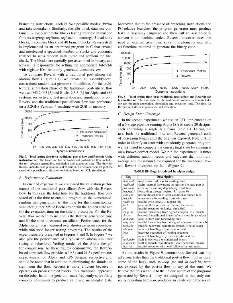
In our first experiment we compared the validation perfor-mance of the traditional post-silicon flow with the Reversiflow. In this case the total time for the traditional flow con-sisted of i) the time to create a program on the constrained-random test generation, ii) the time for the instruction setsimulator (either M5 or Bochs) to obtain the golden state andiii) the execution time on the silicon prototype. For the Re-versi flow we need to include i) the Reversi generation timeand ii) the time to execute on silicon. Performance for theAlpha design was measured over shorter program sequences,while x86 used longer testing programs. The results of theexperiments are presented in Figures 7 and 8. In Figure 7 wealso plot the performance of a typical pre-silicon simulator(using a behavioral Verilog model of the Alpha design)for comparison. As these figures demonstrate, the Reversi-based approach flow provides a 19.5x and 21.5x performanceimprovement for Alpha and x86 designs, respectively. Itshould be noted that in addition to eliminating the simulationstep from the flow, Reversi is more efficient because itoperates on pre-assembled blocks. In a traditional approach,on the other hand, the generator must frequently solve fairlycomplex constraints to produce valid and meaningful tests.
Moreover, due to the presence of branching instructions andPC-relative branches, the program generator must producetests in assembly language and then call an assembler toconvert it to machine codes. Reversi, however, does notneed an external assembler, since it implements internallyall functions required to generate the binary code.
1
10
100
1000
10000
100000
1000000
K 200K 400K 600K 800K 1000K 1200K 1400K
Traditional Post-Si
Reversi
Tota
l tim
e (
ms)
0K 200K 400K 600K 800K 1000K 1200K 1400K
Dynamic instructions
Fig. 8. Total testing time for a traditional post-si flow and Reversi: x86instruction set. The total time for the traditional post-silicon flow includesthe test program generation, simulation and execution time. The time forReversi includes test generation and execution.
C. Design Error Coverage
In the second experiment, we use an RTL implementationof a 5-stage pipeline running Alpha ISA to create 20 designs,each containing a single bug from Table III. During thetest, both the traditional flow and Reversi generated codeof increasing length until the bug was exposed. Note that, inorder to identify an error with a randomly generated program,we first need to compute the correct final state by running iton a known-correct model. We run the experiment 10 timeswith different random seeds and calculate the minimum,average and maximum time required for the traditional flowand Reversi to expose the fault (Figure 9).
TABLE III- Bugs introduced in Alpha design.
Bug Descriptionld st addr load to store address forwarding faultregfile rd faulty internal forwarding in register file read port Afwd mem error in forwarding dependency resolutionfwd reg31 forwarding through register 31 (const 0)ucbr cbr unconditional branch after conditional branch failsfwd wb unnecessary forwarding from wb stageregfile wr invalid write access to register fileflush pipeline flush on specific register file accesssrl invalid execution of logical right shiftscmp cbr invalid forwarding from signed compare to a branchcbr st backward conditional branch after a store is not takenld st data load to store data forwarding faultucmp cbr invalid forwarding from unsigned compare to a branchback cbr specific backward conditional branch is never takenadd over incorrect handling of overflow on addloop incorrect execution of looping sequencejsr incorrect handling of jsr with invalid addressback ucbr fault in backward unconditional branchsh back br fault in branch resolution for short backward branchld arith invalid execution of a load followed by arithmetic
As the results in Figure 9 demonstrate, Reversi can findall errors faster than the traditional post-si flow. Furthermore,some of the bugs, such as loop, jsr and sh back br, werenot exposed by the post-si flow in any of the runs. Webelieve that this was due to the unique nature of the programsgenerated by Reversi - they are designed so that only cor-rectly operating hardware produces an easily verifiable result.

�
��
�
�
��
���
���
���
����
��
����� �
���
����
���
������
���
����
����
����
��
����� �
���
� ��� ��
���
�����
������
���
����
��
���
�����
����
����
����
����
��� ��
�
����
�����
����
����
��
������
�
��������!� "#���$%�
�������
&��""���!�"�'"��������!� "#���$%�
(�)
�() �� �� ��
���
����
��
����� �
���
������
���
����
���
����
����
����
��
������
� ���
���
����
��
����� �
���
���
�����
���
�����
������
���
����
����
��� ��
�
����
�����
����
����
��
����
����
��
�
�
��
���
���
�*��
("����"�
�"�
+�
���"�
��",
��-
�(�)
��
�(.)
�(�)
)
�(�)
�/.
��
�)
/�
��)
��)
.)��)
���.
Fig. 9. Average time to discover bugs in the traditional post-silicon flow and Reversi. The experiments were run 10 times with different random seedsand the minimum, average and maximum times to expose each bug are plotted. Note that bugs loop, jsr and sh back br were not exposed by a traditionalpost-silicon flow based on a constrained-random test generator.
Thus, incorrect operations can be detected immediately atexecution completion. Moreover, Reversi creates complexprograms with multiple interleaved execution flows thatexercise all instructions in the ISA, exposing these corner-case bugs.
It’s worth observing that, in several experiments with thetraditional flow (such as fw wb), a shorter random programexposed a bug, while a longer sequence of instructions didnot. This is possible due to the random nature of the test:later instructions may overwrite registers/memory locationsthat contain incorrect values, thus eliminating the evidenceof the bug. Therefore, a longer random program does notnecessarily find more bugs than a shorter one. Reversi pro-grams, on the other hand, are designed so that any behaviorcorrupting the processor state is propagated to the exit pointand exposed.
VI. CONCLUSIONS AND FUTURE WORK
In this paper we presented a novel post-silicon valida-tion methodology that exploits the performance potential ofhardware prototypes and bypasses the design simulation steprequired by traditional flows. Test programs that our Reversiframework generates work to explore complex executionscenarios and, most importantly, have identical initial andfinal architectural states eliminating the need for a simulatorto check the correctness of the test. The programs are builtfrom sequences of functional blocks, which modify the stateof the machine, and they are combined with inverse blocksto undo earlier operations and restore the original machinestate. Individual blocks are parameterized and may consistof one or several instructions, selected randomly from ablock database during test generation. Reversi handles alltypes of instructions: arithmetic (integer and floating point),logic, memory accesses, control flow and control registeroperations. As our results demonstrate, Reversi creates pro-grams capable of finding more bugs faster than traditionalconstrained-random test generation techniques. Moreover,due to the omission of the architectural simulation step,Reversi can generate and run tests 20x faster than tools basedon a traditional post-silicon flow.
In the future, we plan to optimize Reversi to only requireminimal resources, such as OS primitives, I/O drivers, etc.,so that we can run it on the same board as the device undertest. The programs in this case can be generated by a morereliable or thoroughly tested previous generation processormore efficiently than in our experiments. We also foresee thepossibility of running our generator on a subset of the coresof a multi-core device-under-test. This would allow Reversito achieve generation speeds that significantly exceed theperformance of today’s methods and approach a throughputcomparable to actual silicon.
REFERENCES
[1] Constrained-random test generation and functional coverage with Vera.Technical report, Synopsys, Inc, Feb. 2003.
[2] Revision Guide for AMD Athlon 64 and AMD Opteron Processors,Aug. 2005.
[3] Intel Core2 Duo Desktop Processor E6000 and E4000 SequenceSpecification Update, Nov. 2007.
[4] Intel Core2 Extreme Quad-Core Processor QX6000 Sequence and IntelCore2 Quad Processor Q6000 Sequence, Nov. 2007.
[5] The M5 simulator system, Nov. 2007. http://www.m5sim.org.[6] The open source IA-32 emulation project, Sept. 2007.
http://bochs.sourceforge.net/.[7] A. Adir et al. Genesys-pro: Innovations in test program generation for
functional processor verification. IEEE Design & Test of Computers,21(2):84–93, Mar. 2004.
[8] B. Bentley and R. Gray. Validating the Intel Pentium 4 microprocessor.Intel Technology Journal, Q1, pages 1–8, 2001.
[9] K. H. Bierman et al. U.S. Patent no. 7133818: Method and apparatusfor accelerated post-silicon testing and random number generation,Nov. 2006.
[10] T. Litt. Support for debugging in the Alpha 21364 microprocessor. InInternational Test Conference, Oct. 2002.
[11] M. L. Bushnell, V. D. Agrawal. Essentials of Electronic Testing forDigital, Memory & Mixed-Signal VLSI circuits. Springer, 2000.
[12] M. Melani et al. An integrated flow from pre-silicon simulationto post-silicon verification. In Research in Microelectronics andElectronics 2006, Ph. D., pages 205–208, June 2006.
[13] P. T. Barch et al. U.S. Patent no. 5923836: Testing integrated circuitdesigns on a computer simulation using modified serialized scanpatterns, Nov. 2006.
[14] R. Emek et al. X-Gen: A random test-case generator for systems andSoCs. In International Workshop on High Level Design Validationand Test, pages 145–150, Oct. 2002.
[15] R. Raina and R. Molyneaux. Random self-test method - applicationson PowerPC microprocessor caches. In Proceedings of the Great LakesSymposium on VLSI, Feb. 1998.
[16] H. Rotithor. Post-silicon validation methodology for microprocessors.IEEE Design & Test of Computers, 17(4):77–88, Oct. 2000.