Embed Size (px)
Citation preview
HRO 6 07/26/12
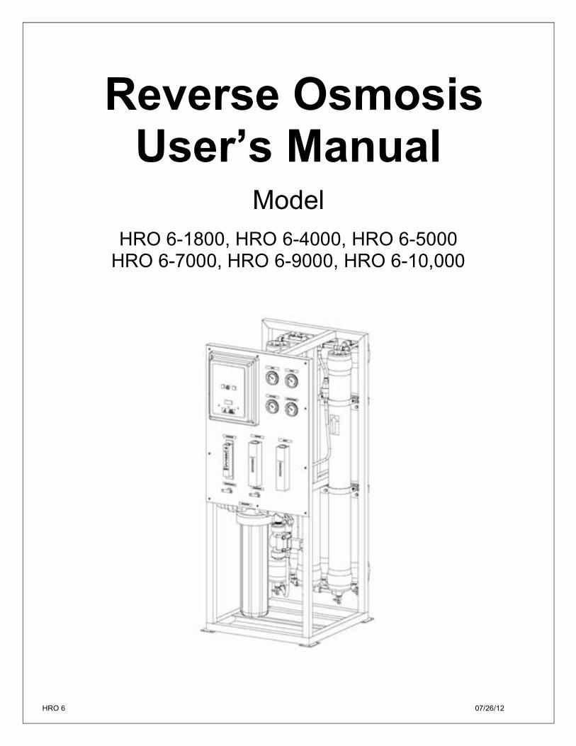
Reverse Osmosis User’s Manual
Model
HRO 6-1800, HRO 6-4000, HRO 6-5000 HRO 6-7000, HRO 6-9000, HRO 6-10,000

2 HRO 6 07/26/12

3 HRO 6 07/26/12
This Page Intentionally Left Blank
4 HRO 6 07/26/12
TABLE OF CONTENTS
INTRODUCTION ................................................................................................................................... 5
SAFETY ................................................................................................................................................ 5
FEED WATER AND OPERATION SPECIFICATIONS .................................................................................. 6
REJECTION, RECOVERY AND FLOW RATES ............................................................................................ 6
SYSTEM REQUIREMENTS AND OPERATION GUIDELINES ....................................................................... 7
MEMBRANE ELEMENTS ....................................................................................................................... 9
HRO 6-1800, HRO 6-4000, HRO 6-5000, HRO 6-7000, HRO 6-9000, HRO 6-10,000 . Error! Bookmark not
defined.
SYSTEM IDENTIFICATION ................................................................................................................... 17
SYSTEM PURGING .............................................................................................................................. 22
INITIAL START-UP .............................................................................................................................. 23
OPERATING DO’s AND DON’Ts ........................................................................................................... 25
OPERATION AND MAINTENANCE ....................................................................................................... 25
MEMBRANE REMOVAL AND REPLACEMENT ...................................................................................... 27
FLUSHING THE SYSTEM ...................................................................................................................... 29
PREPARING UNIT FOR STORAGE OR SHIPMENT ................................................................................. 29
REVERSE OSMOSIS TROUBLESHOOTING ............................................................................................ 30
TEMPERATURE CORRECTION FACTORS FOR MEMBRANE ................................................................... 32
OPERATION ....................................................................................................................................... 34
DRAWINGS ........................................................................................................................................ 35
5 HRO 6 07/26/12
INTRODUCTION Your HRO 6-Series system is a durable piece of equipment which, with proper care, will last for many years. This User’s Manual outlines installation, operation, maintenance, and troubleshooting details vital to the sustained performance of your system. The test results which are included with this User’s Manual indicate your system’s permeate (product) and concentrate (waste) test results. If your system is altered at the site of operation or if the feed water conditions change, please contact your local dealer or distributor to determine the proper recovery for your application. NOTE: IN ORDER TO MAINTAIN THE MANUFACTURER’S WARRANTY, AN OPERATING LOG MUST BE MAINTAINED AND COPIES WILL NEED TO BE SENT TO YOUR LOCAL DEALER OR DISTRIBUTOR FOR REVIEW. NOTE: PRIOR TO OPERATING OR SERVICING THE REVERSE OSMOSIS SYSTEM, THIS USER’S MANUAL MUST BE READ AND FULLY UNDERSTOOD. KEEP THIS AND OTHER ASSOCIATED INFORMATION FOR FUTURE REFERENCE AND FOR NEW OPERATORS OR QUALIFIED PERSONNEL NEAR THE SYSTEM.
SAFETY The Safety section of this User’s Manual outlines the various safety headings used throughout this manual’s text and are enhanced and defined below: NOTE: INDICATES STATEMENTS THAT PROVIDE FURTHER INFORMATION AND CLARIFICATION.
CAUTION: INDICATES STATEMENTS THAT ARE USED TO IDENTIFY CONDITIONS OR PRACTICES THAT COULD RESULT IN EQUIPMENT OR OTHER PROPERTY DAMAGE.
WARNING: INDICATES STATEMENTS THAT ARE USED TO IDENTIFY CONDITIONS OR PRACTICES THAT COULD RESULT IN INJURY OR LOSS OF LIFE. FAILURE TO FOLLOW WARNINGS COULD RESULT IN SERIOUS INJURY OR EVEN DEATH.
DO NOT UNDER ANY CIRCUMSTANCE; REMOVE ANY CAUTION, WARNING, OR OTHER DESCRIPTIVE LABELS FROM THE SYSTEM.
6 HRO 6 07/26/12
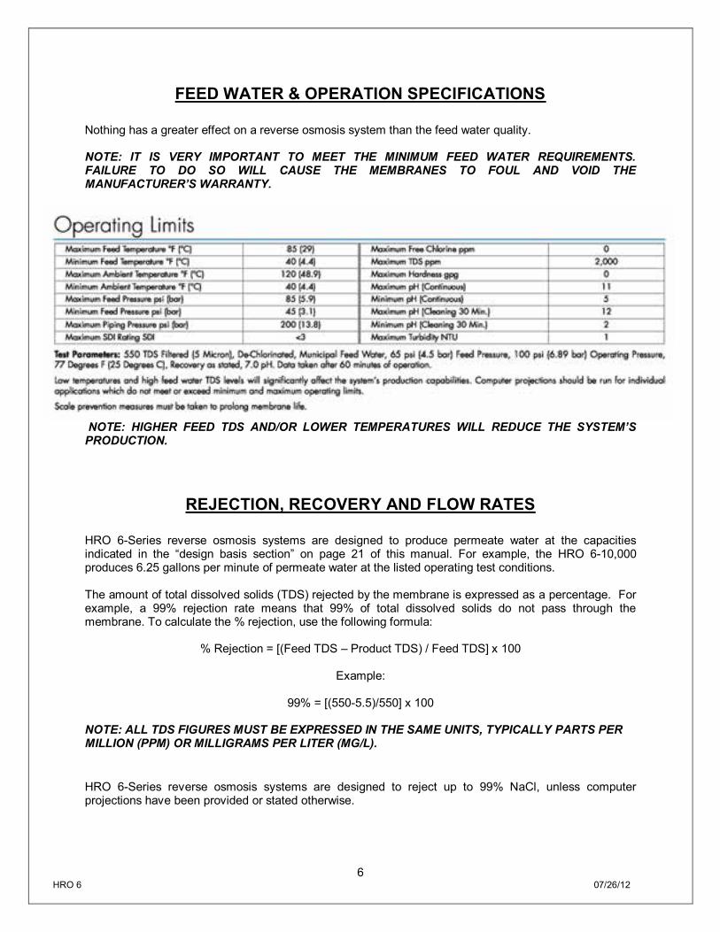
FEED WATER & OPERATION SPECIFICATIONS Nothing has a greater effect on a reverse osmosis system than the feed water quality. NOTE: IT IS VERY IMPORTANT TO MEET THE MINIMUM FEED WATER REQUIREMENTS. FAILURE TO DO SO WILL CAUSE THE MEMBRANES TO FOUL AND VOID THE MANUFACTURER’S WARRANTY.
NOTE: HIGHER FEED TDS AND/OR LOWER TEMPERATURES WILL REDUCE THE SYSTEM’S PRODUCTION.
REJECTION, RECOVERY AND FLOW RATES HRO 6-Series reverse osmosis systems are designed to produce permeate water at the capacities indicated in the “design basis section” on page 21 of this manual. For example, the HRO 6-10,000 produces 6.25 gallons per minute of permeate water at the listed operating test conditions. The amount of total dissolved solids (TDS) rejected by the membrane is expressed as a percentage. For example, a 99% rejection rate means that 99% of total dissolved solids do not pass through the membrane. To calculate the % rejection, use the following formula:
% Rejection = [(Feed TDS – Product TDS) / Feed TDS] x 100
Example:
99% = [(550-5.5)/550] x 100
NOTE: ALL TDS FIGURES MUST BE EXPRESSED IN THE SAME UNITS, TYPICALLY PARTS PER MILLION (PPM) OR MILLIGRAMS PER LITER (MG/L). HRO 6-Series reverse osmosis systems are designed to reject up to 99% NaCl, unless computer projections have been provided or stated otherwise.
7 HRO 6 07/26/12
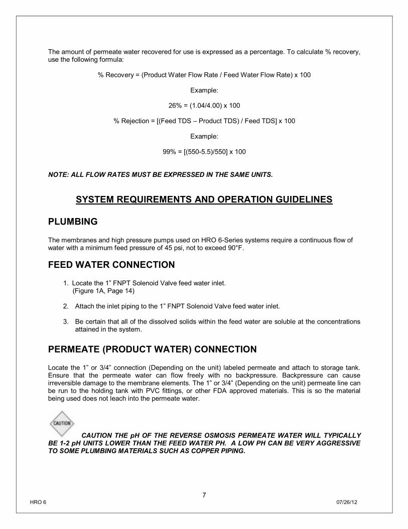
The amount of permeate water recovered for use is expressed as a percentage. To calculate % recovery, use the following formula:
% Recovery = (Product Water Flow Rate / Feed Water Flow Rate) x 100
Example:
26% = (1.04/4.00) x 100
% Rejection = [(Feed TDS – Product TDS) / Feed TDS] x 100
Example:
99% = [(550-5.5)/550] x 100
NOTE: ALL FLOW RATES MUST BE EXPRESSED IN THE SAME UNITS.
SYSTEM REQUIREMENTS AND OPERATION GUIDELINES PLUMBING The membranes and high pressure pumps used on HRO 6-Series systems require a continuous flow of water with a minimum feed pressure of 45 psi, not to exceed 90°F. FEED WATER CONNECTION
1. Locate the 1” FNPT Solenoid Valve feed water inlet. (Figure 1A, Page 14)
2. Attach the inlet piping to the 1” FNPT Solenoid Valve feed water inlet.
3. Be certain that all of the dissolved solids within the feed water are soluble at the concentrations
attained in the system. PERMEATE (PRODUCT WATER) CONNECTION Locate the 1” or 3/4” connection (Depending on the unit) labeled permeate and attach to storage tank. Ensure that the permeate water can flow freely with no backpressure. Backpressure can cause irreversible damage to the membrane elements. The 1” or 3/4” (Depending on the unit) permeate line can be run to the holding tank with PVC fittings, or other FDA approved materials. This is so the material being used does not leach into the permeate water.
CAUTION THE pH OF THE REVERSE OSMOSIS PERMEATE WATER WILL TYPICALLY BE 1-2 pH UNITS LOWER THAN THE FEED WATER PH. A LOW PH CAN BE VERY AGGRESSIVE TO SOME PLUMBING MATERIALS SUCH AS COPPER PIPING.
8 HRO 6 07/26/12
CONCENTRATE (WASTE WATER) CONNECTION Locate the 1” or 3/4” connection (Depending on the unit) labeled concentrate and attach to a drain. Run the concentrate line to an open drain in a free and unrestricted manner (no backpressure). It is advised that an air-break be used on the concentrate line to prevent siphoning of water from the pressure vessels when the system is in standby.
CAUTION: ANY RESTRICTIONS OR BLOCKAGE IN THE DRAIN LINE CAN CAUSE BACKPRESSURE, WHICH WILL INCREASE THE SYSTEM’S OPERATING PRESSURE. THIS CAN RESULT IN DAMAGE TO THE SYSTEM’S MEMBRANES AND COMPONENTS. ELECTRICAL The motor used on the HRO 6-Series systems are pump and motor combination. The motor is available in 220/460 Volt, 50/60 Hertz, 1 Phase/3 phase. Each HRO 6-Series system is equipped with a 5 foot electrical cord. Ensure that the electrical circuit supplying the system is compatible with the requirements of the specific HRO 6 model you are installing. NOTE: IT’S RECOMMENDED THAT A LICENSED ELECTRICIAN WIRE YOUR SYSTEM IN ACCORDANCE WITH LOCAL AND NATIONAL ELECTRICAL CODES (NEC).
WARNING: TO REDUCE THE RISK OF ELECTRICAL SHOCK, THE INCOMING POWER SUPPLY MUST INCLUDE A PROTECTIVE EARTH GROUND. HRO 6-Series systems are typically controlled with a liquid level switch in a storage tank. The liquid level switch turns the system on when the water level in the tank drops, and off when the tank is full. Liquid level switches can be obtained by your local dealer or distributor. If a liquid level switch is to be used, install it at this time. PRE-FILTRATION HRO 6-Series systems are supplied with a 5 micron sediment filter. Change the cartridge once a month or when a 10-15 psi differential exists between the two pre-filter gauges. Ask your local dealer or distributor about Pre-Filtration systems, if required. NOTE: THE SYSTEM MUST BE OPERATED USING FILTERED FEED WATER ONLY. PUMP The pump used on the HRO 6-Series systems is of the multi-stage centrifugal stainless steel type. Follow these guidelines to ensure proper operation of the pump:
The pump must NEVER be run dry. Operating the pump without sufficient feed water will damage the pump.
9 HRO 6 07/26/12
ALWAYS feed the pump with filtered water. The pump is susceptible to damage from sediment and debris.
If any damage occurs to your system’s pump a re-build kit may be available. Contact your local
dealer or distributor and inform them of your system’s model and pump size. MOUNTING The free standing system should be bolted down in compliance with local regulation standards or securely fastened.
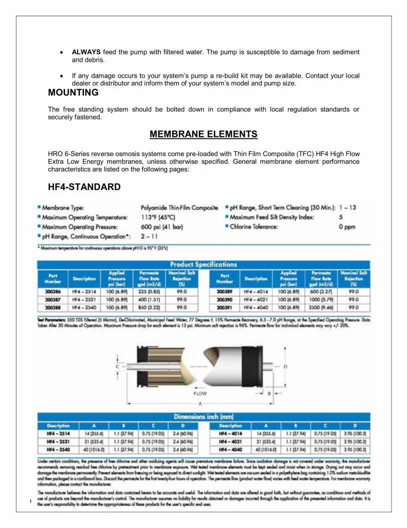
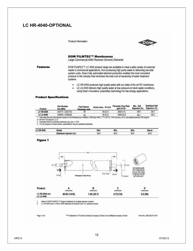
MEMBRANE ELEMENTS HRO 6-Series reverse osmosis systems come pre-loaded with Thin Film Composite (TFC) HF4 High Flow Extra Low Energy membranes, unless otherwise specified. General membrane element performance characteristics are listed on the following pages: HF4-STANDARD
10 HRO 6 07/26/12
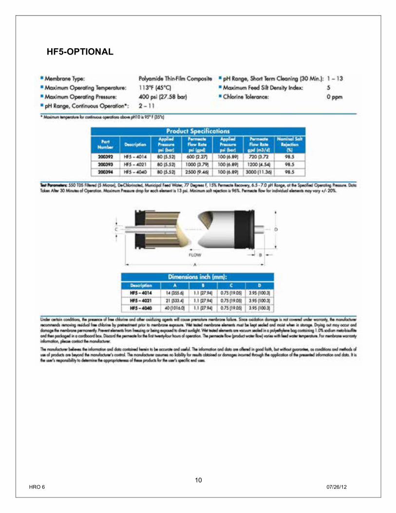
HF5-OPTIONAL
11 HRO 6 07/26/12
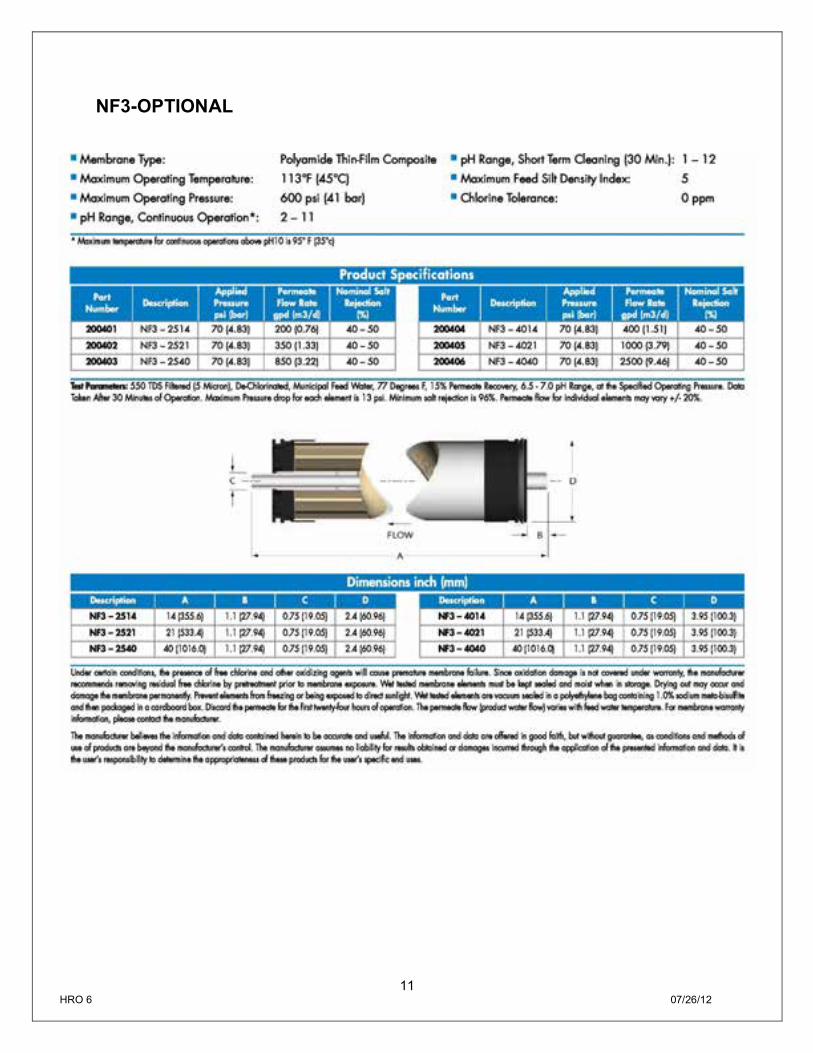
NF3-OPTIONAL
12 HRO 6 07/26/12
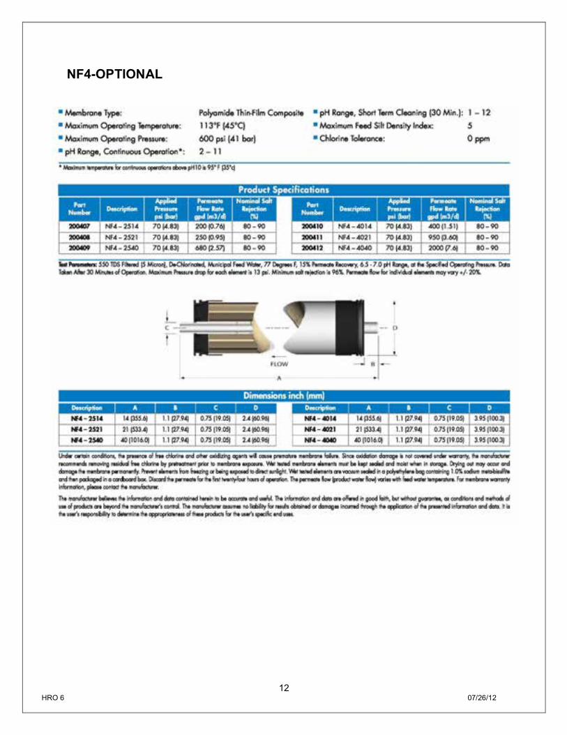
NF4-OPTIONAL
13 HRO 6 07/26/12
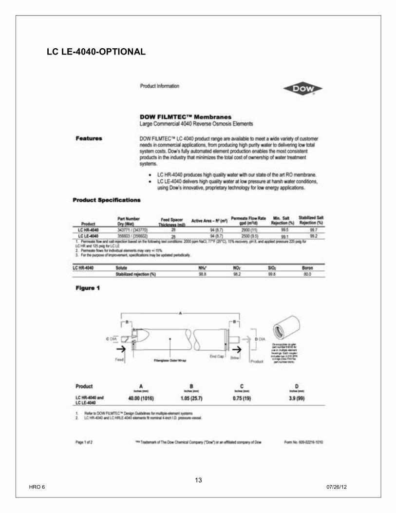
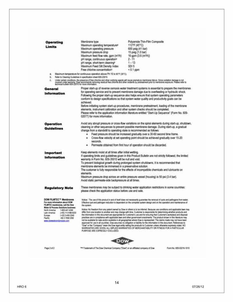
LC LE-4040-OPTIONAL
14 HRO 6 07/26/12
15 HRO 6 07/26/12
LC HR-4040-OPTIONAL

16 HRO 6 07/26/12
17 HRO 6 07/26/12
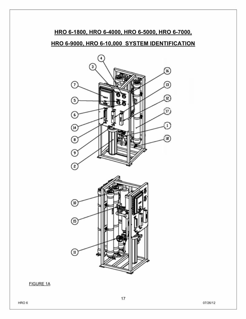
HRO 6-1800, HRO 6-4000, HRO 6-5000, HRO 6-7000,
HRO 6-9000, HRO 6-10,000 SYSTEM IDENTIFICATION
FIGURE 1A
18 HRO 6 07/26/12
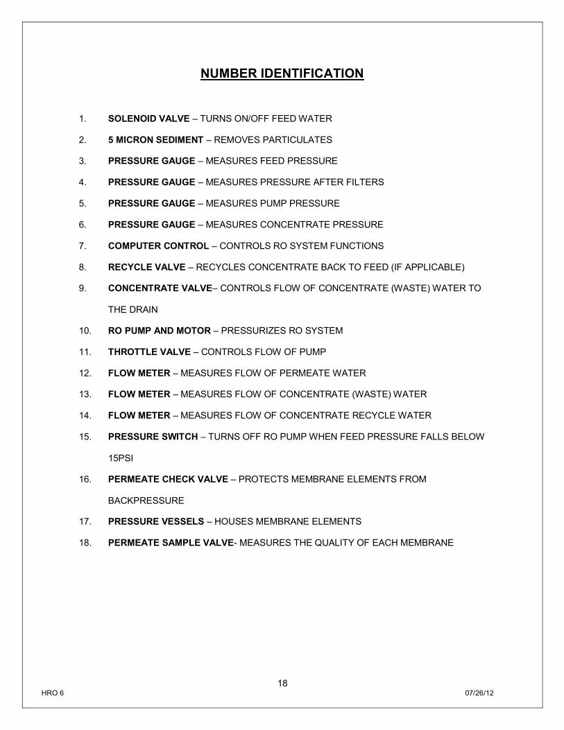
NUMBER IDENTIFICATION
1. SOLENOID VALVE – TURNS ON/OFF FEED WATER
2. 5 MICRON SEDIMENT – REMOVES PARTICULATES
3. PRESSURE GAUGE – MEASURES FEED PRESSURE
4. PRESSURE GAUGE – MEASURES PRESSURE AFTER FILTERS
5. PRESSURE GAUGE – MEASURES PUMP PRESSURE
6. PRESSURE GAUGE – MEASURES CONCENTRATE PRESSURE
7. COMPUTER CONTROL – CONTROLS RO SYSTEM FUNCTIONS
8. RECYCLE VALVE – RECYCLES CONCENTRATE BACK TO FEED (IF APPLICABLE)
9. CONCENTRATE VALVE– CONTROLS FLOW OF CONCENTRATE (WASTE) WATER TO
THE DRAIN
10. RO PUMP AND MOTOR – PRESSURIZES RO SYSTEM
11. THROTTLE VALVE – CONTROLS FLOW OF PUMP
12. FLOW METER – MEASURES FLOW OF PERMEATE WATER
13. FLOW METER – MEASURES FLOW OF CONCENTRATE (WASTE) WATER
14. FLOW METER – MEASURES FLOW OF CONCENTRATE RECYCLE WATER
15. PRESSURE SWITCH – TURNS OFF RO PUMP WHEN FEED PRESSURE FALLS BELOW
15PSI
16. PERMEATE CHECK VALVE – PROTECTS MEMBRANE ELEMENTS FROM
BACKPRESSURE
17. PRESSURE VESSELS – HOUSES MEMBRANE ELEMENTS
18. PERMEATE SAMPLE VALVE- MEASURES THE QUALITY OF EACH MEMBRANE
19 HRO 6 07/26/12
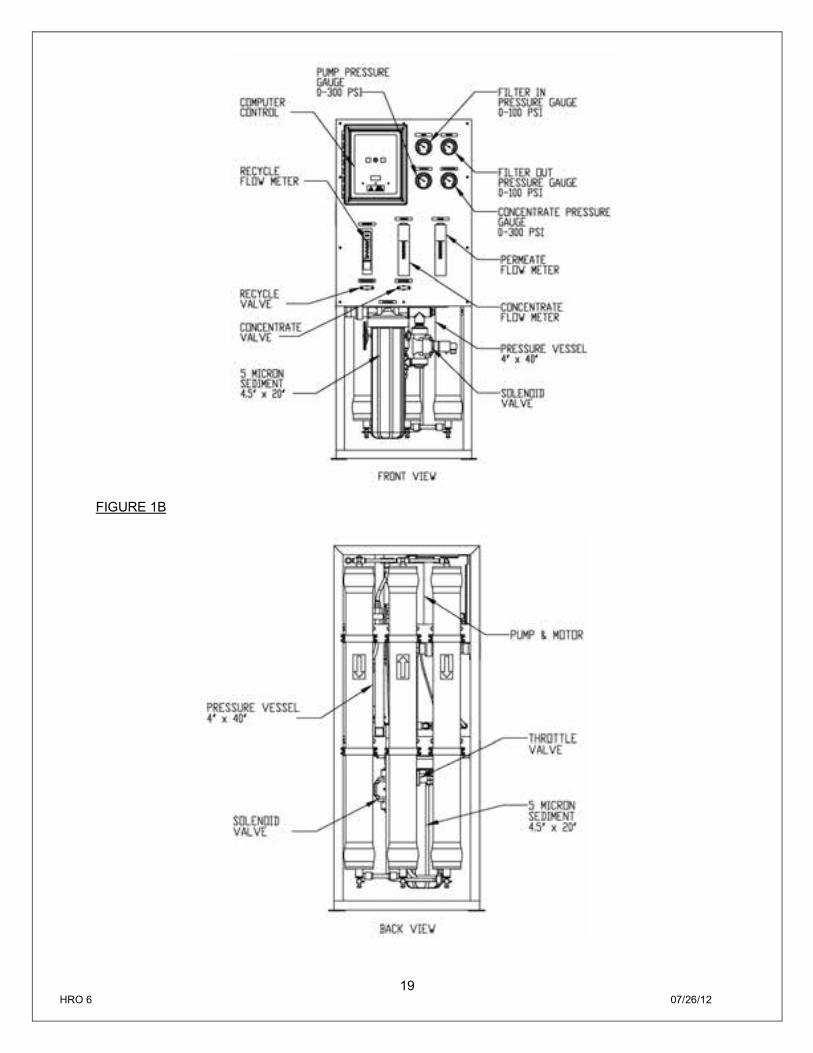
FIGURE 1B
20 HRO 6 07/26/12
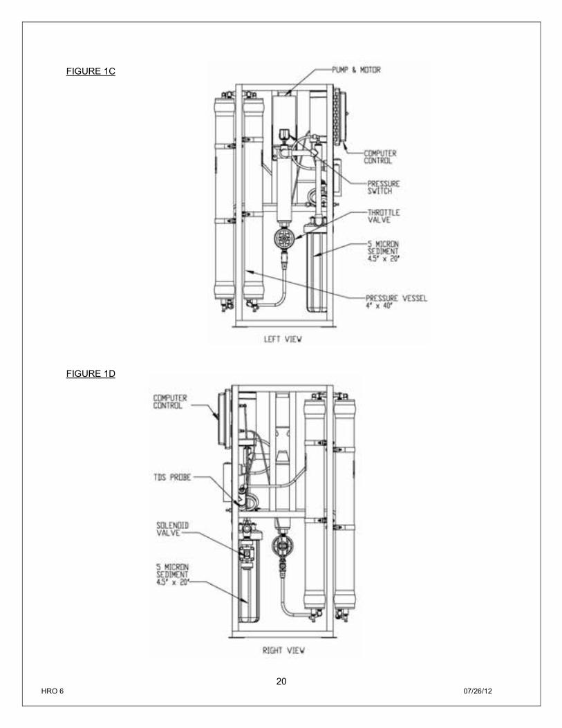
FIGURE 1C
FIGURE 1D
21 HRO 6 07/26/12
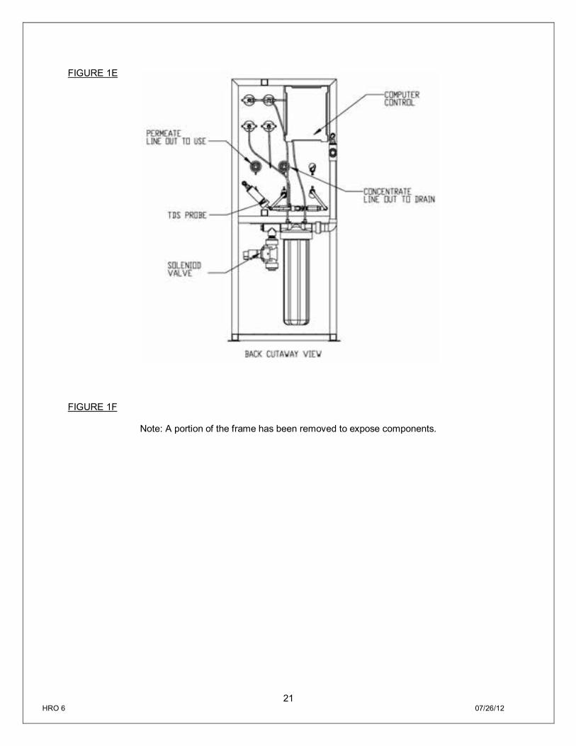
FIGURE 1E
FIGURE 1F
Note: A portion of the frame has been removed to expose components.
22 HRO 6 07/26/12
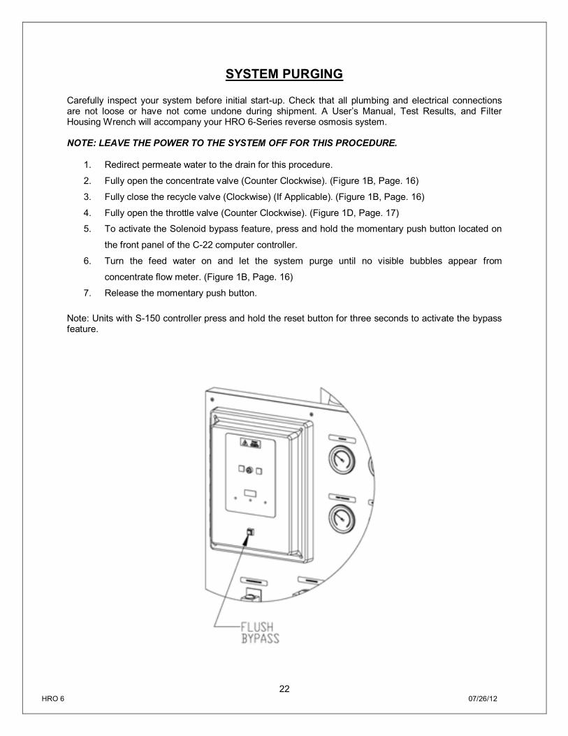
SYSTEM PURGING Carefully inspect your system before initial start-up. Check that all plumbing and electrical connections are not loose or have not come undone during shipment. A User’s Manual, Test Results, and Filter Housing Wrench will accompany your HRO 6-Series reverse osmosis system. NOTE: LEAVE THE POWER TO THE SYSTEM OFF FOR THIS PROCEDURE.
1. Redirect permeate water to the drain for this procedure.
2. Fully open the concentrate valve (Counter Clockwise). (Figure 1B, Page. 16)
3. Fully close the recycle valve (Clockwise) (If Applicable). (Figure 1B, Page. 16)
4. Fully open the throttle valve (Counter Clockwise). (Figure 1D, Page. 17)
5. To activate the Solenoid bypass feature, press and hold the momentary push button located on
the front panel of the C-22 computer controller.
6. Turn the feed water on and let the system purge until no visible bubbles appear from
concentrate flow meter. (Figure 1B, Page. 16)
7. Release the momentary push button.
Note: Units with S-150 controller press and hold the reset button for three seconds to activate the bypass feature.
23 HRO 6 07/26/12
FIGURE 2
INITIAL START-UP 1. Keep the permeate water line to drain for this procedure.
2. Fully open the concentrate valve (Counter Clockwise). (Figure 1B, Page. 16)
3. Fully close the recycle valve (Clockwise)(If Applicable). (Figure 1B, Page. 16)
4. Adjust the throttle valve at 50% open (Counter Clockwise). (Figure 1D, Page. 17)
5. Turn the RO system on and adjust the concentrate (waste) valve, recycle valve (If Applicable), and
the throttle valve to the designed flow and pressure. (Figure 1B, Page. 16)
6. Inspect the system for leaks.
7. Allow the system to run 30 minutes to flush the preservative solution from the system.
8. After 30 minutes, shut down the system.
9. Re-direct the permeate water back to the tank and then turn the system back on.
10. Record the readings daily for a week; after one week record the readings once a week.
24 HRO 6 07/26/12
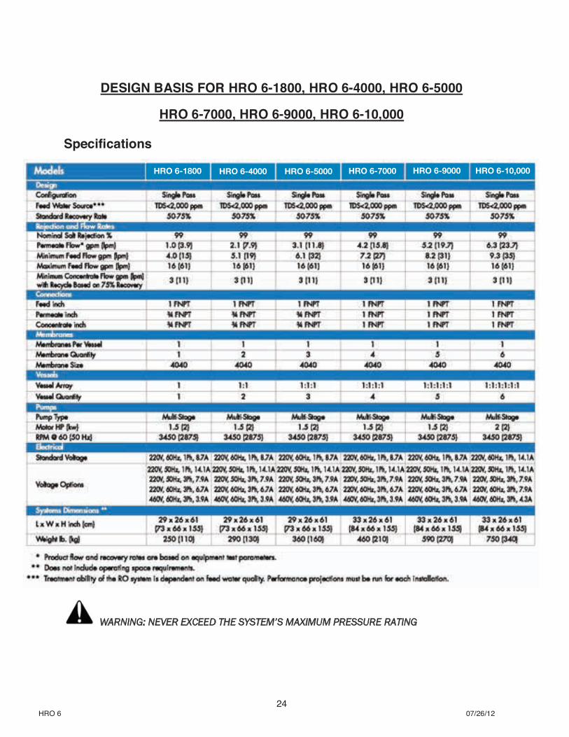
DESIGN BASIS FOR HRO 6-1800, HRO 6-4000, HRO 6-5000
HRO 6-7000, HRO 6-9000, HRO 6-10,000 Specifications
WARNING: NEVER EXCEED THE SYSTEM’S MAXIMUM PRESSURE RATING
HRO 6-1800 HRO 6-4000 HRO 6-5000 HRO 6-7000 HRO 6-9000 HRO 6-10,000
25 HRO 6 07/26/12
OPERATING DO’s AND DONT’S DO:
Change the cartridge filters regularly
Monitor the system and keep a daily log
Run the system, as much as possible, on a continuous basis.
Adjust the system recovery to the recommended value
Always feed the pump with filtered water.
DON’T:
Permit chlorine to enter or be present in the feed water
Shut down the system for extended periods
Close the throttle valve completely
Operate the system with insufficient feed flow
Operate the pump dry
OPERATION AND MAINTENANCE The reverse osmosis process causes the concentration of impurities. The impurities may precipitate (fall out of solution) when their concentration reaches saturation levels. NOTE: PRECIPITATION CAN SCALE OR FOUL MEMBRANES AND MUST BE PREVENTED. Check your feed water chemistry and pre-treat the water and/or reduce the system’s recovery as required. If necessary, consult with your local dealer or distributor. PRE-FILTER PRESSURE GAUGES Pre-filter gauges measure the feed water pressure when it enters and exits the pre-filter. A pressure differential of 10 - 15 psi or more on the two pressure gauges indicates that the pre-filters require servicing. PUMP PRESSURE AND CONCENTRATE PRESSURE GAUGES Pump and concentrate gauges measure the pressure of water exiting the multistage pump and the pressure of concentrate water as it exits the pressure vessel array. Comparison of the pump output and concentrate pressures allows for the establishment of a baseline pressure differential. If the pressure differential increases over time from this baseline, it would be an indication that the reverse osmosis membranes need to be inspected.
26 HRO 6 07/26/12
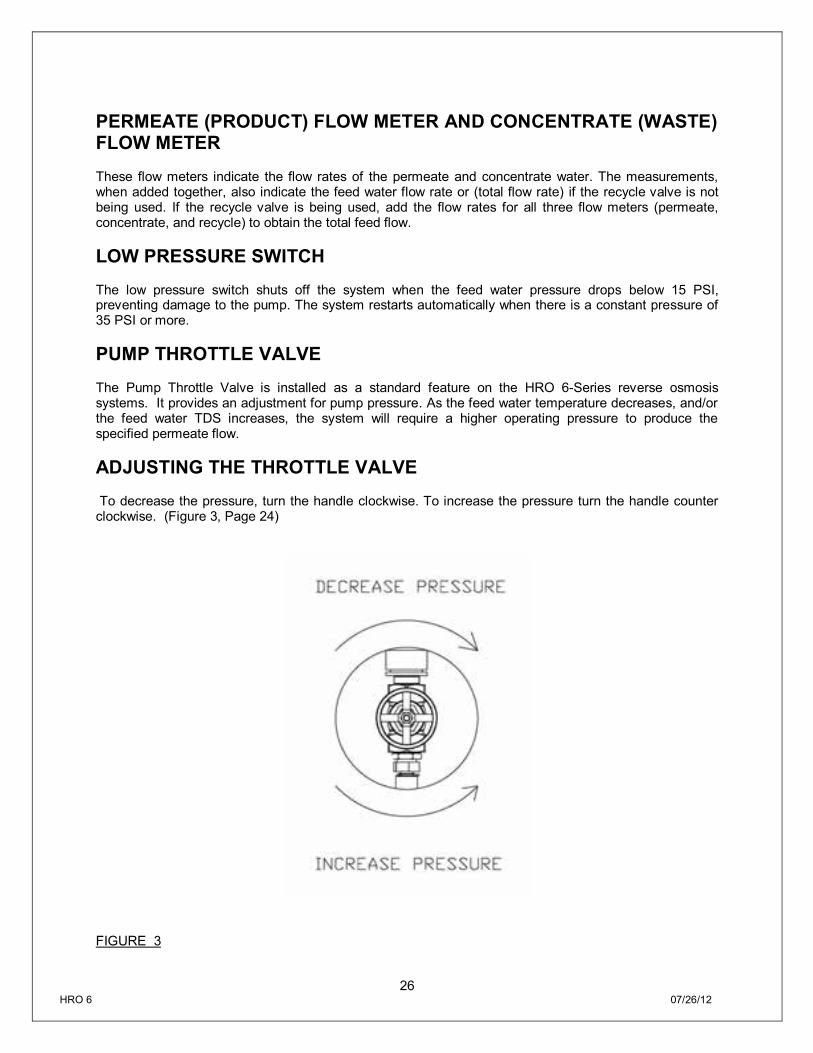
PERMEATE (PRODUCT) FLOW METER AND CONCENTRATE (WASTE) FLOW METER These flow meters indicate the flow rates of the permeate and concentrate water. The measurements, when added together, also indicate the feed water flow rate or (total flow rate) if the recycle valve is not being used. If the recycle valve is being used, add the flow rates for all three flow meters (permeate, concentrate, and recycle) to obtain the total feed flow. LOW PRESSURE SWITCH The low pressure switch shuts off the system when the feed water pressure drops below 15 PSI, preventing damage to the pump. The system restarts automatically when there is a constant pressure of 35 PSI or more. PUMP THROTTLE VALVE The Pump Throttle Valve is installed as a standard feature on the HRO 6-Series reverse osmosis systems. It provides an adjustment for pump pressure. As the feed water temperature decreases, and/or the feed water TDS increases, the system will require a higher operating pressure to produce the specified permeate flow. ADJUSTING THE THROTTLE VALVE To decrease the pressure, turn the handle clockwise. To increase the pressure turn the handle counter clockwise. (Figure 3, Page 24)
FIGURE 3
27 HRO 6 07/26/12
MEMBRANE REMOVAL AND REPLACEMENT Replacing membranes in the pressure vessels is an easy process if you have the proper information and tools at hand. Please refer to the following instructions when removing and replacing membrane elements:
WARNING: ALL PRESSURE GAUGES MUST READ ZERO BEFORE PROCEEDING. BEFORE ATTEMPTING, DISCONNECT THE POWER FROM THE SYSTEM AND BLEED ALL WATER PRESSURE FROM THE SYSTEM.
1. Remove the end plugs from the top of the pressure vessels. This is done by removing the two half-moon retaining disks using a #5 Allen wrench; the end plugs should then freely slide out of the pressure vessel.
2. Remove the replacement membrane element(s) from the shipping box; the membrane(s) should be contained within a plastic oxygen barrier bag.
NOTE: WEAR GLOVES FOR THE FOLLOWING STEPS IN ORDER NOT TO CONTAMINATE THE MEMBRANE.
3. Cut the bag open as close as possible to the seal at one end of the bag, so the bag may be re-used if necessary.
4. Make sure that all parts are clean and free from dirt. Examine the brine seal, and permeate tube
for nicks or cuts. Replace the O-rings or brine seal if damaged.
5. Flow directions should be observed for installation of each element into their respective pressure vessels.
REPLACING THE MEMBRANE ELEMENT:
WARNING: THE BRINE SEAL MUST BE IN THE SAME POSITION FOR EACH MEMBRANE ELEMENT HOUSING, SO MARK EACH HOUSING PRIOR TO REMOVING THE MEMBRANE ELEMENTS. THE BRINE SEAL IS A RUBBER SEAL THAT PROTRUDES ON ONE SIDE OF THE MEMBRANE AND IS ALWAYS ON THE FEED SIDE OF THE MEMBRANE ELEMENT.
1. Remove one membrane element at a time from the pressure vessels, from the top of each housing. Long nose pliers may be necessary to pull the old membrane element out of the membrane element housing.
2. Lubricate the brine seal with a non-petroleum based lubricant, such as Dow Corning® 111.
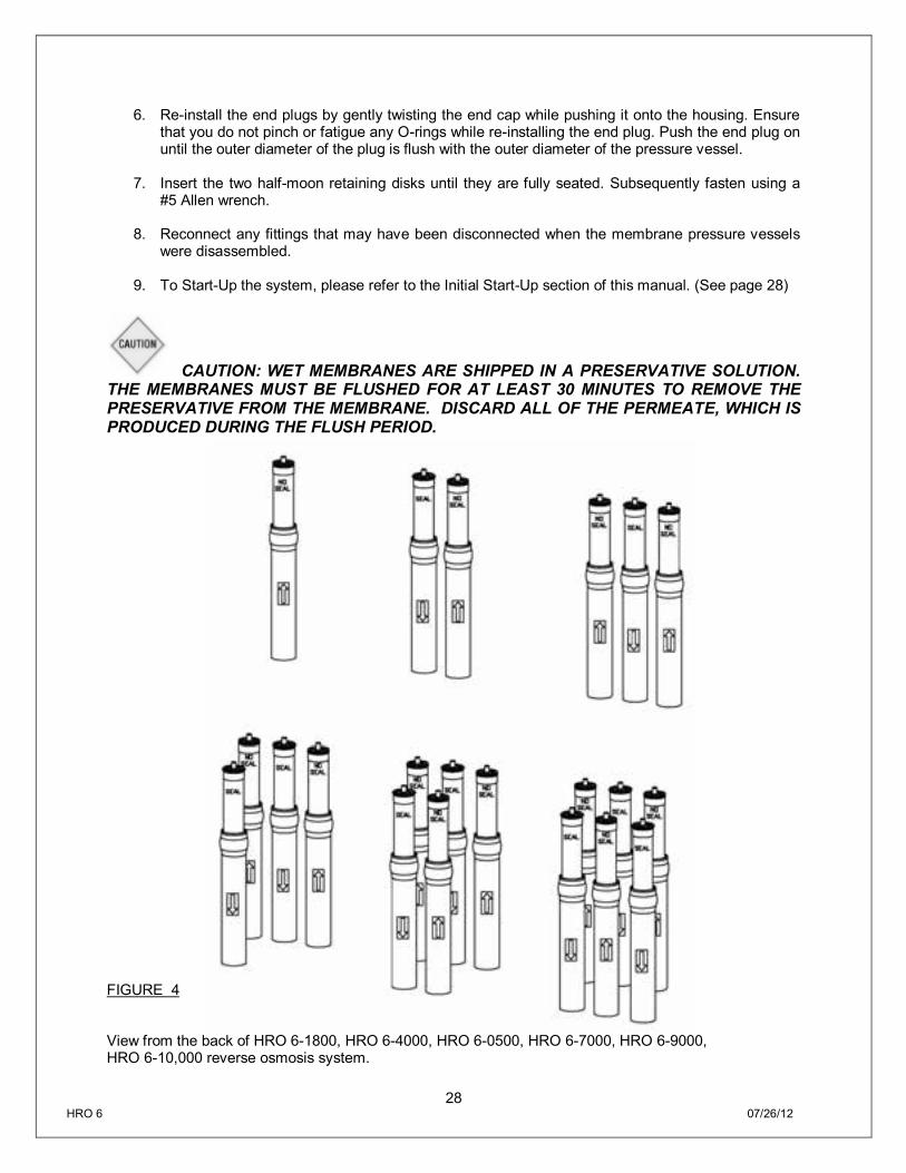
3. Install membranes with brine seal location depicted in (Figure 4, Page 26).
4. For brine seals that are on the bottom: At a slight angle insert the membrane while slightly
rotating the element being careful not to tear or flip the brine seal. A slow twisting motion should be used to insert the membrane element, for every couple of turns pull up ½” to make sure the brine seal doesn’t flip.
5. With a smooth and constant motion, push the membrane element into the housing so the brine
seal enters the housing without coming out of the brine seal groove.
28 HRO 6 07/26/12
6. Re-install the end plugs by gently twisting the end cap while pushing it onto the housing. Ensure that you do not pinch or fatigue any O-rings while re-installing the end plug. Push the end plug on until the outer diameter of the plug is flush with the outer diameter of the pressure vessel.
7. Insert the two half-moon retaining disks until they are fully seated. Subsequently fasten using a
#5 Allen wrench.
8. Reconnect any fittings that may have been disconnected when the membrane pressure vessels were disassembled.
9. To Start-Up the system, please refer to the Initial Start-Up section of this manual. (See page 28)
CAUTION: WET MEMBRANES ARE SHIPPED IN A PRESERVATIVE SOLUTION. THE MEMBRANES MUST BE FLUSHED FOR AT LEAST 30 MINUTES TO REMOVE THE PRESERVATIVE FROM THE MEMBRANE. DISCARD ALL OF THE PERMEATE, WHICH IS PRODUCED DURING THE FLUSH PERIOD.
FIGURE 4 View from the back of HRO 6-1800, HRO 6-4000, HRO 6-0500, HRO 6-7000, HRO 6-9000, HRO 6-10,000 reverse osmosis system.
29 HRO 6 07/26/12
FLUSHING THE SYSTEM The system should be flushed weekly to remove sediment from the surface of the membranes. To manually flush the system, follow the preceding steps:
1. The system must be operating during the flush procedure.
2. Fully open the concentrate valve. (Figure 1B, Page. 16)
3. Allow the system to run for 10 to 20 minutes.
4. After 10 to 20 minutes, close the concentrate valve to its previous setting. Ensure the proper concentrate flow rate is going to the drain.
5. The system is now ready to operate.
PREPARING UNIT FOR STORAGE OR SHIPMENT
PRIOR TO SHIPPING OR STORING YOUR SYSTEM, THE SYSTEM SHOULD BE CLEANED WITH AN APPROPRIATE CLEANER, FLUSHED WITH WATER, AND PROTECTED FROM BIOLOGICAL ATTACK WITH AN APPROPRIATE SOLUTION FOR MEMBRANE ELEMENTS. THE MEMBRANE HOUSING(S) AND PLUMBING LINES OF THE SYSTEM MUST BE COMPLETELY DRAINED. ANY WATER REMAINING IN THE PLUMBING OF A SYSTEM MAY FREEZE, CAUSING SERIOUS DAMAGE. PREPARING SYSTEM FOR STORAGE:
1. Fully immerse the elements in the membrane housing in a solution of 2% M-100, venting the air
outside of the pressure vessels. Use the overflow technique: circulate the M-100 solution in such a way that the remaining air in the system is minimized after the recirculation is completed. After the pressure vessel is filled, the M-100 solution should be allowed to overflow through an opening located higher than the upper end of the highest pressure vessel being filled.
2. Separate the preservation solution from the air outside by closing all valves.
3. Repeat this process at least once a month. During the shutdown period, the plant must be kept frost-free, or the temperature must not exceed 113°F (45°C).
PREPARING UNIT FOR SHIPMENT:
1. Disconnect the inlet, concentrate, pre-filter, and permeate plumbing.
2. Drain all water from the pre-filter cartridge housings by unscrewing the housings, removing the
pre-filter cartridges, and drain the water from the housings.
3. Disconnect the tubing from the connectors on the permeate and concentrate inlets and outlets.
4. Fully open the concentrate valve.
5. Drain the flow meters.
6. Allow the system to drain for a minimum of eight hours or until the opened ports quit dripping.
7. After draining is complete, reconnect all of the plumbing.
30 HRO 6 07/26/12
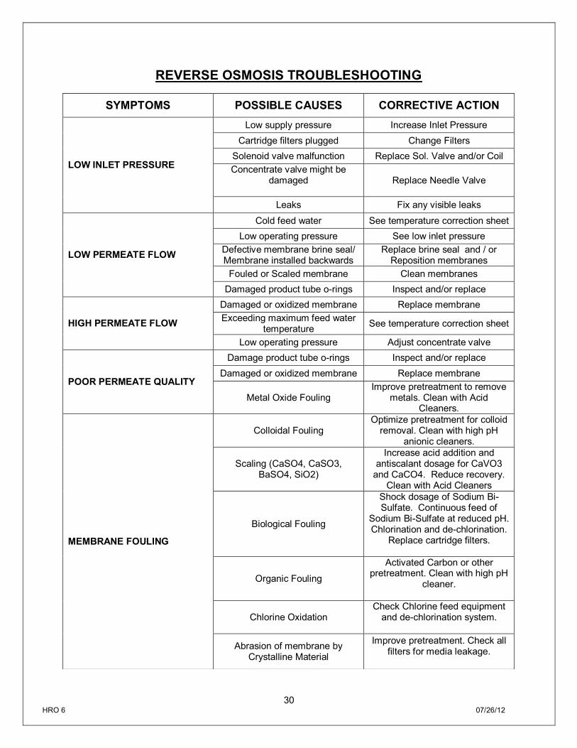
REVERSE OSMOSIS TROUBLESHOOTING
SYMPTOMS POSSIBLE CAUSES CORRECTIVE ACTION
LOW INLET PRESSURE
Low supply pressure Increase Inlet Pressure Cartridge filters plugged Change Filters
Solenoid valve malfunction Replace Sol. Valve and/or Coil Concentrate valve might be
damaged
Replace Needle Valve
Leaks Fix any visible leaks
LOW PERMEATE FLOW
Cold feed water See temperature correction sheet Low operating pressure See low inlet pressure
Defective membrane brine seal/ Membrane installed backwards
Replace brine seal and / or Reposition membranes
Fouled or Scaled membrane Clean membranes Damaged product tube o-rings Inspect and/or replace
HIGH PERMEATE FLOW
Damaged or oxidized membrane Replace membrane Exceeding maximum feed water
temperature See temperature correction sheet
Low operating pressure Adjust concentrate valve
POOR PERMEATE QUALITY
Damage product tube o-rings Inspect and/or replace Damaged or oxidized membrane Replace membrane
Metal Oxide Fouling Improve pretreatment to remove
metals. Clean with Acid Cleaners.
MEMBRANE FOULING
Colloidal Fouling Optimize pretreatment for colloid
removal. Clean with high pH anionic cleaners.
Scaling (CaSO4, CaSO3, BaSO4, SiO2)
Increase acid addition and antiscalant dosage for CaVO3
and CaCO4. Reduce recovery. Clean with Acid Cleaners
Biological Fouling
Shock dosage of Sodium Bi-Sulfate. Continuous feed of
Sodium Bi-Sulfate at reduced pH. Chlorination and de-chlorination.
Replace cartridge filters.
Organic Fouling
Activated Carbon or other pretreatment. Clean with high pH
cleaner.
Chlorine Oxidation Check Chlorine feed equipment
and de-chlorination system.
Abrasion of membrane by Crystalline Material
Improve pretreatment. Check all filters for media leakage.
31 HRO 6 07/26/12
ABNORMAL PERMEATE FLOW As time progresses, the efficiency of the membrane will be reduced. In general, the salt rejection does not change significantly until two or three years after installation when operated on properly pretreated feed water. The permeate flow rate will begin to decline slightly after one year of operation, but can be extended with diligent flushing and cleaning of the system. A high pH and/or precipitation of hardness can cause premature loss in rejection. Permeate flow should be within 20% of the rated production, after correcting the feed water temperatures above or below 77°F. Check your permeate flow meter to determine the permeate flow rate. NOTE: TO DETERMINE THE TEMPERATURE CORRECTION FACTOR, LOCATE THE TEMPERATURE CORRECTION TABLE IN THIS USER’S MANUAL AND FOLLOW THE DIRECTIONS
32 HRO 6 07/26/12
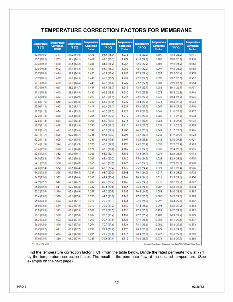
TEMPERATURE CORRECTION FACTORS FOR MEMBRANE
Find the temperature correction factor (TCF) from the table below. Divide the rated permeate flow at 77°F by the temperature correction factor. The result is the permeate flow at the desired temperature. (See example on the next page)
33 HRO 6 07/26/12
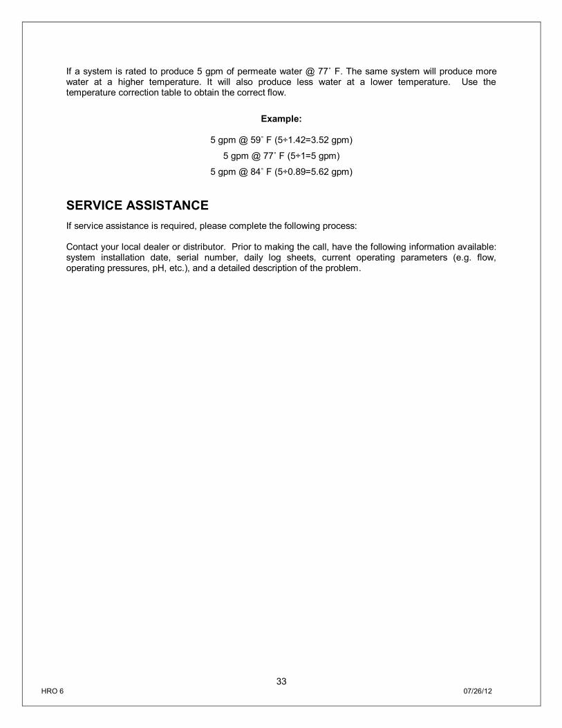
If a system is rated to produce 5 gpm of permeate water @ 77˚ F. The same system will produce more water at a higher temperature. It will also produce less water at a lower temperature. Use the temperature correction table to obtain the correct flow.
Example:
5 gpm @ 59˚ F (5÷1.42=3.52 gpm)
5 gpm @ 77˚ F (5÷1=5 gpm)
5 gpm @ 84˚ F (5÷0.89=5.62 gpm)
SERVICE ASSISTANCE If service assistance is required, please complete the following process: Contact your local dealer or distributor. Prior to making the call, have the following information available: system installation date, serial number, daily log sheets, current operating parameters (e.g. flow, operating pressures, pH, etc.), and a detailed description of the problem.
34 HRO 6 07/26/12
OPERATION Company: ____________________
Date of Start-Up: ___________________
Location: ____________________
Date of Last Cleaning: ___________________
Week Of: ____________________
System Serial #: ____________________
DATE
TIME
HOUR OF OPERATION
FILTER INLET PRESSURE (PSI) FILTER OUTLET PRESSURE
(PSI) CONCENTRATE PRESSURE
(PSI) PUMP DISCHARGE PRESSURE
(PSI)
FEED FLOW (GPM)
PERMEATE FLOW (GPM)
CONCENTRATE FLOW (GPM)
RECYCLE FLOW (GPM)
RECOVERY %
FEED TEMPERATURE
FEED TDS (PPM)
PERMEATE TDS (PPM)
REJECTION %
FEED PH
PERMEATE PH
SCALE INHIBITOR FEED (PPM)
IRON (mg/L)
FREE CHLORINE (mg/L)
HARDNESS (GPG CaCO3)
SAMF-111 Rev. A 12/18/08 21
SERVICE ASSISTANCE If service assistance is required, please complete the following process: Contact your local dealer or distributor. Prior to making the call, have the following information available: system installation date, serial number, daily log sheets, current operating parameters (e.g. flow, operating pressures, pH, etc.), and a detailed description of the problem.
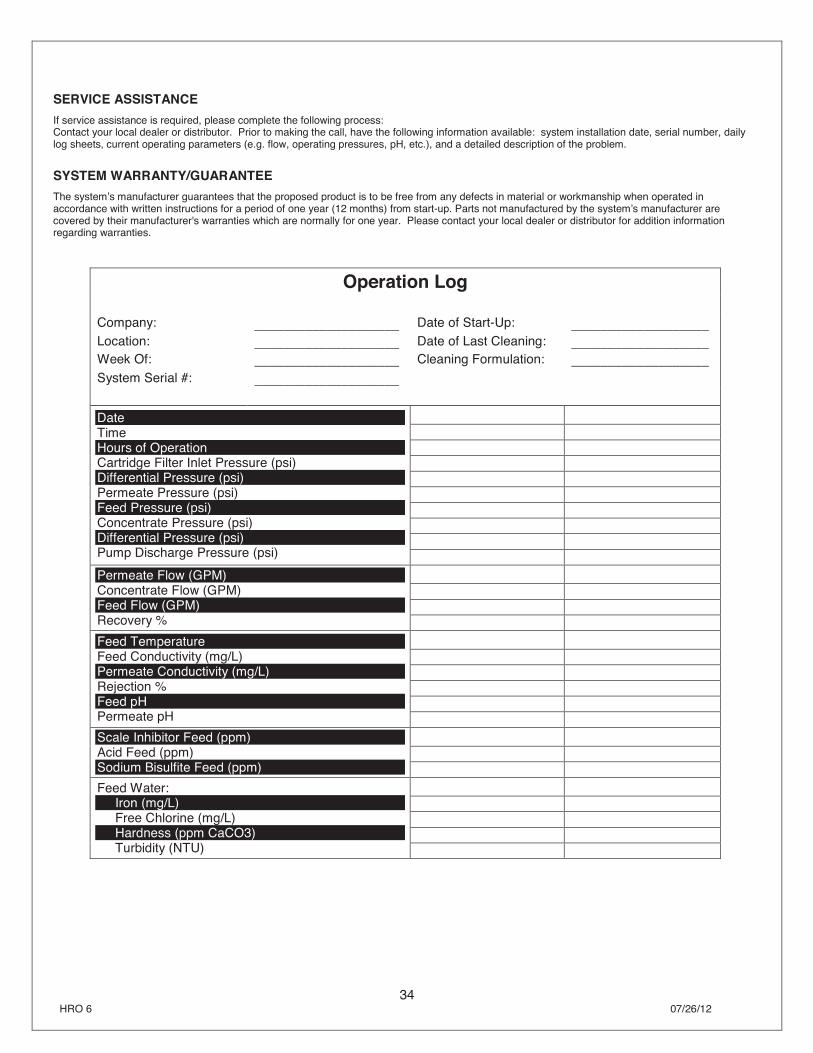
SYSTEM WARRANTY/GUARANTEEThe system’s manufacturer guarantees that the proposed product is to be free from any defects in material or workmanship when operated in accordance with written instructions for a period of one year (12 months) from start-up. Parts not manufactured by the system’s manufacturer are covered by their manufacturer's warranties which are normally for one year. Please contact your local dealer or distributor for addition information regarding warranties.
Operation Log
Company: ____________________ Date of Start-Up: ___________________ Location: ____________________ Date of Last Cleaning: ___________________ Week Of: ____________________ Cleaning Formulation: ___________________ System Serial #: ____________________
Date Time Hours of Operation Cartridge Filter Inlet Pressure (psi) Differential Pressure (psi) Permeate Pressure (psi) Feed Pressure (psi) Concentrate Pressure (psi) Differential Pressure (psi) Pump Discharge Pressure (psi)
Permeate Flow (GPM) Concentrate Flow (GPM) Feed Flow (GPM) Recovery %
Feed Temperature Feed Conductivity (mg/L) Permeate Conductivity (mg/L) Rejection % Feed pH Permeate pH
Scale Inhibitor Feed (ppm) Acid Feed (ppm) Sodium Bisulfite Feed (ppm)
Feed Water: Iron (mg/L) Free Chlorine (mg/L) Hardness (ppm CaCO3) Turbidity (NTU)
35 HRO 6 07/26/12
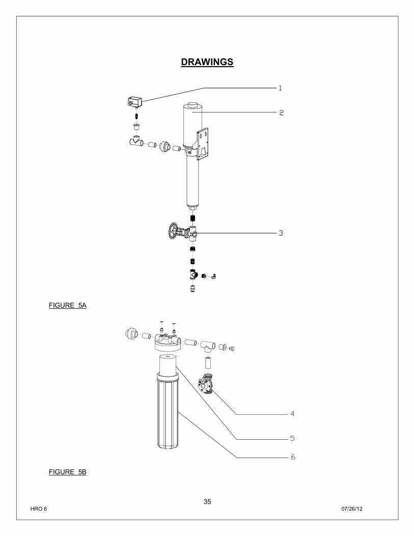
DRAWINGS
FIGURE 5A
FIGURE 5B
36 HRO 6 07/26/12
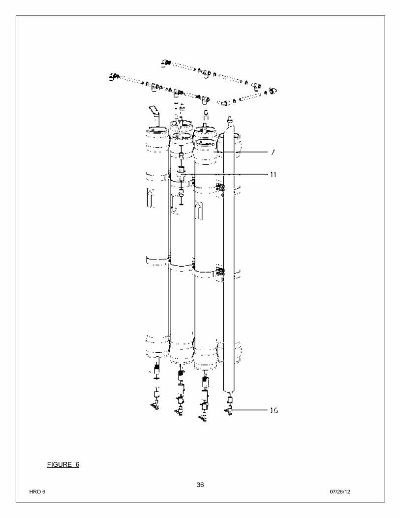
FIGURE 6
37 HRO 6 07/26/12
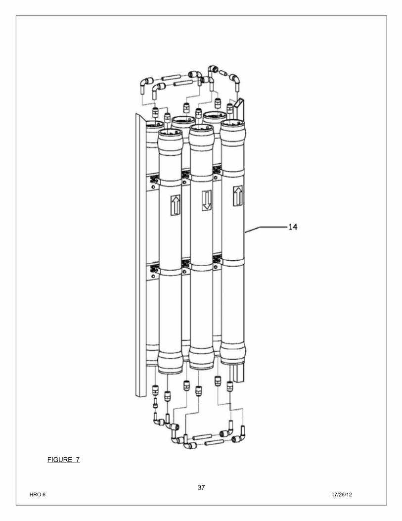
FIGURE 7
38 HRO 6 07/26/12
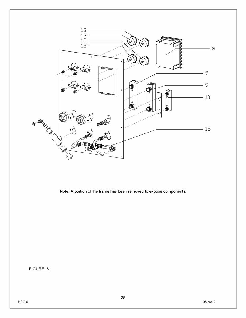
Note: A portion of the frame has been removed to expose components.
FIGURE 8

39 HRO 6 07/26/12
HRO 6-1800 SYSTEM PART LIST
Item No. Quantity Part Number Description
1 1 200906 SWITCH, PRESSURE, LOW, N/O 15-30, ¼” FNPT
2 1 200795 PUMP, MULTI-STAGE, 1.5 HP, 110/220V, 1PH 10GBS1514Q4, GOULDS
3 1 205903 VALVE, GLOBE, SS, 1” FNPT
4 1 204914 VALVE, SOLENOID, N/C, UL, 220V, 1” FNPT
5 1 200640 CART, SEDIMENT, PLEATED, 4.5” x 20”, 5 MIC
6 1 203649 HOUSING, FILT, BLK/BLU, 4.5” x 20”, 1” FNPT
7 1 202929 HOUSING, MEM, FRP, 4040, ½”P x ¾”C FNPT
8 1 204207 CONTROLLER, COMPUTER, C22, 120/220V, 1PH
9 1 200899 METER, FLOW, PM, 1-10 GPM, 1”x 1”
10 2 200898 METER, FLOW, PM, 0-5 GPM, ½”x ½” MNPT
11 1 200965 VALVE, CHECK, PP, ½” FNPT x ½” FNPT
12 2 200904 GAUGE, BKM, FILL, 0-300 PSI/BAR, 2.5” DIA
13 2 204165 GAUGE, BKM, FILL, 0-100 PSI/BAR, 2.5” DIA
14 1 200391 MEMBRANE, HF4, 4040
15 2 201006 VALVE, NEEDLE, SS 316, ½” FNPT
16 1 203606 VALVE, BALL, 1/4" MNPT X 1/4" QC
40 HRO 6 07/26/12
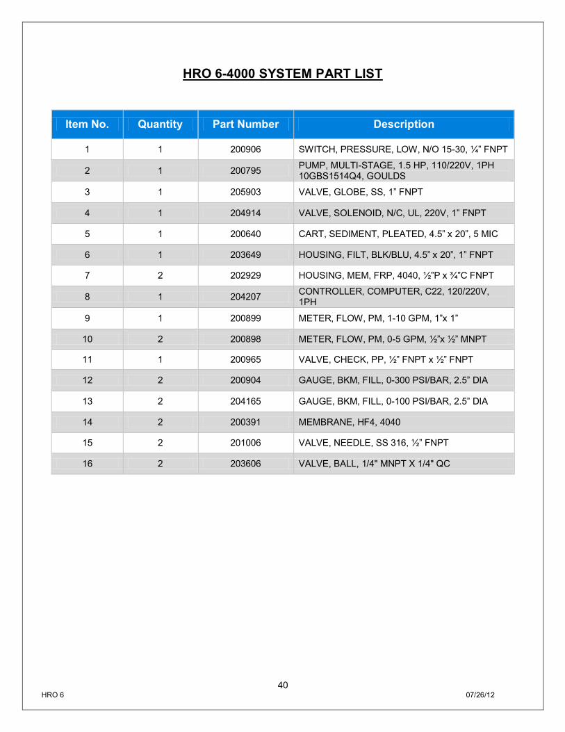
HRO 6-4000 SYSTEM PART LIST
Item No. Quantity Part Number Description
1 1 200906 SWITCH, PRESSURE, LOW, N/O 15-30, ¼” FNPT
2 1 200795 PUMP, MULTI-STAGE, 1.5 HP, 110/220V, 1PH 10GBS1514Q4, GOULDS
3 1 205903 VALVE, GLOBE, SS, 1” FNPT
4 1 204914 VALVE, SOLENOID, N/C, UL, 220V, 1” FNPT
5 1 200640 CART, SEDIMENT, PLEATED, 4.5” x 20”, 5 MIC
6 1 203649 HOUSING, FILT, BLK/BLU, 4.5” x 20”, 1” FNPT
7 2 202929 HOUSING, MEM, FRP, 4040, ½”P x ¾”C FNPT
8 1 204207 CONTROLLER, COMPUTER, C22, 120/220V, 1PH
9 1 200899 METER, FLOW, PM, 1-10 GPM, 1”x 1”
10 2 200898 METER, FLOW, PM, 0-5 GPM, ½”x ½” MNPT
11 1 200965 VALVE, CHECK, PP, ½” FNPT x ½” FNPT
12 2 200904 GAUGE, BKM, FILL, 0-300 PSI/BAR, 2.5” DIA
13 2 204165 GAUGE, BKM, FILL, 0-100 PSI/BAR, 2.5” DIA
14 2 200391 MEMBRANE, HF4, 4040
15 2 201006 VALVE, NEEDLE, SS 316, ½” FNPT
16 2 203606 VALVE, BALL, 1/4" MNPT X 1/4" QC

41 HRO 6 07/26/12
HRO 6-5000 SYSTEM PART LIST
Item No. Quantity Part Number Description
1 1 200906 SWITCH, PRESSURE, LOW, N/O 15-30, ¼” FNPT
2 1 200795 PUMP, MULTI-STAGE, 1.5 HP, 110/220V, 1PH 10GBS1514Q4, GOULDS
3 1 205903 VALVE, GLOBE, SS, 1” FNPT
4 1 206688 VALVE, SOLENOID, 2-WAY,BRASS, 100–240V, 1” FNPT, ASCO
5 1 200640 CART, SEDIMENT, PLEATED, 4.5” x 20”, 5 MIC
6 1 203649 HOUSING, FILT, BLK/BLU, 4.5” x 20”, 1” FNPT
7 3 202929 HOUSING, MEM, FRP, 4040, ½”P x ¾”C FNPT
8 1 204207 CONTROLLER, COMPUTER, C22, 120/220V, 1PH
9 1 200899 METER, FLOW, PM, 1-10 GPM, 1”x 1”
10 2 200898 METER, FLOW, PM, 0-5 GPM, ½”x ½” MNPT
11 1 200965 VALVE, CHECK, PP, ½” FNPT x ½” FNPT
12 2 200904 GAUGE, BKM, FILL, 0-300 PSI/BAR, 2.5” DIA
13 2 204165 GAUGE, BKM, FILL, 0-100 PSI/BAR, 2.5” DIA
14 3 200391 MEMBRANE, HF4, 4040
15 2 201006 VALVE, NEEDLE, SS 316, ½” FNPT
16 3 203606 VALVE, BALL, 1/4" MNPT X 1/4" QC
42 HRO 6 07/26/12
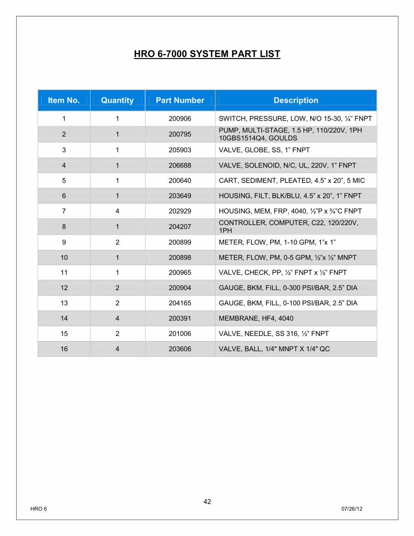
HRO 6-7000 SYSTEM PART LIST
Item No. Quantity Part Number Description
1 1 200906 SWITCH, PRESSURE, LOW, N/O 15-30, ¼” FNPT
2 1 200795 PUMP, MULTI-STAGE, 1.5 HP, 110/220V, 1PH 10GBS1514Q4, GOULDS
3 1 205903 VALVE, GLOBE, SS, 1” FNPT
4 1 206688 VALVE, SOLENOID, N/C, UL, 220V, 1” FNPT
5 1 200640 CART, SEDIMENT, PLEATED, 4.5” x 20”, 5 MIC
6 1 203649 HOUSING, FILT, BLK/BLU, 4.5” x 20”, 1” FNPT
7 4 202929 HOUSING, MEM, FRP, 4040, ½”P x ¾”C FNPT
8 1 204207 CONTROLLER, COMPUTER, C22, 120/220V, 1PH
9 2 200899 METER, FLOW, PM, 1-10 GPM, 1”x 1”
10 1 200898 METER, FLOW, PM, 0-5 GPM, ½”x ½” MNPT
11 1 200965 VALVE, CHECK, PP, ½” FNPT x ½” FNPT
12 2 200904 GAUGE, BKM, FILL, 0-300 PSI/BAR, 2.5” DIA
13 2 204165 GAUGE, BKM, FILL, 0-100 PSI/BAR, 2.5” DIA
14 4 200391 MEMBRANE, HF4, 4040
15 2 201006 VALVE, NEEDLE, SS 316, ½” FNPT
16 4 203606 VALVE, BALL, 1/4" MNPT X 1/4" QC

43 HRO 6 07/26/12
HRO 6-9000 SYSTEM PART LIST
Item No. Quantity Part Number Description
1 1 200906 SWITCH, PRESSURE, LOW, N/O 15-30, ¼” FNPT
2 1 200795 PUMP, MULTI-STAGE, 1.5 HP, 110/220V, 1PH 10GBS1514Q4, GOULDS
3 1 205903 VALVE, GLOBE, SS, 1” FNPT
4 1 204914 VALVE, SOLENOID, N/C, UL, 220V, 1” FNPT
5 1 200640 CART, SEDIMENT, PLEATED, 4.5” x 20”, 5 MIC
6 1 203649 HOUSING, FILT, BLK/BLU, 4.5” x 20”, 1” FNPT
7 5 202929 HOUSING, MEM, FRP, 4040, ½”P x ¾”C FNPT
8 1 204207 CONTROLLER, COMPUTER, C22, 120/220V, 1PH
9 2 200899 METER, FLOW, PM, 1-10 GPM, 1”x 1”
10 1 200898 METER, FLOW, PM, 0-5 GPM, ½”x ½” MNPT
11 1 200965 VALVE, CHECK, PP, ½” FNPT x ½” FNPT
12 2 200904 GAUGE, BKM, FILL, 0-300 PSI/BAR, 2.5” DIA
13 2 204165 GAUGE, BKM, FILL, 0-100 PSI/BAR, 2.5” DIA
14 5 200391 MEMBRANE, HF4, 4040
15 2 201006 VALVE, NEEDLE, SS 316, ½” FNPT
16 5 203606 VALVE, BALL, 1/4" MNPT X 1/4" QC

44 HRO 6 07/26/12
HRO 6-10,000 SYSTEM PART LIST
Item No. Quantity Part Number Description
1 1 200906 SWITCH, PRESSURE, LOW, N/O 15-30, ¼” FNPT
2 1 206427 PUMP, MULTISTAGE,2HP,115/208-230V,1PH,TEFC,18GBS2014N4
3 1 205903 VALVE, GLOBE, SS, 1” FNPT
4 1 204914 VALVE, SOLENOID, N/C, UL, 220V, 1” FNPT
5 1 200640 CART, SEDIMENT, PLEATED, 4.5” x 20”, 5 MIC
6 1 203649 HOUSING, FILT, BLK/BLU, 4.5” x 20”, 1” FNPT
7 6 202929 HOUSING, MEM, FRP, 4040, ½”P x ¾”C FNPT
8 1 204207 CONTROLLER, COMPUTER, C22, 120/220V, 1PH
9 2 200899 METER, FLOW, PM, 1-10 GPM, 1”x 1”
10 1 200898 METER, FLOW, PM, 0-5 GPM, ½”x ½” MNPT
11 1 200965 VALVE, CHECK, PP, ½” FNPT x ½” FNPT
12 2 200904 GAUGE, BKM, FILL, 0-300 PSI/BAR, 2.5” DIA
13 2 204165 GAUGE, BKM, FILL, 0-100 PSI/BAR, 2.5” DIA
14 6 200391 MEMBRANE, HF4, 4040
15 2 201006 VALVE, NEEDLE, SS 316, ½” FNPT
16 6 203606 VALVE, BALL, 1/4" MNPT X 1/4" QC
45 HRO 6 07/26/12
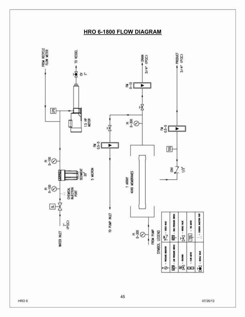
HRO 6-1800 FLOW DIAGRAM
46 HRO 6 07/26/12
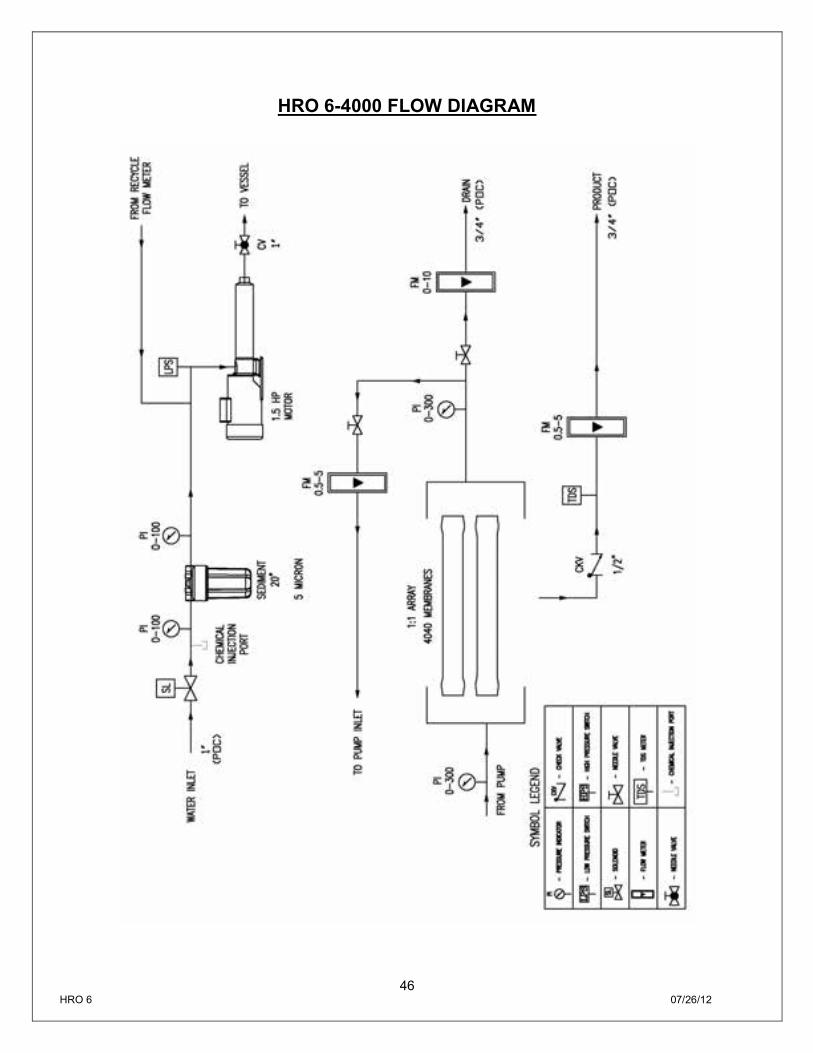
HRO 6-4000 FLOW DIAGRAM
47 HRO 6 07/26/12
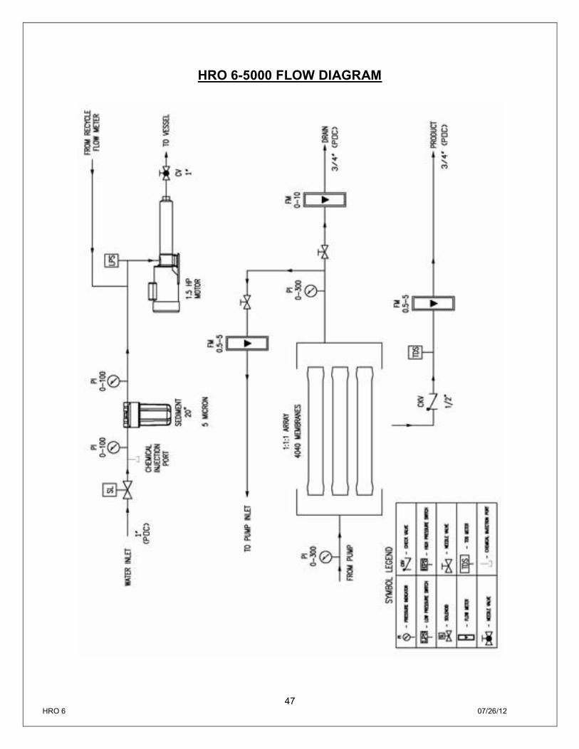
HRO 6-5000 FLOW DIAGRAM
48 HRO 6 07/26/12
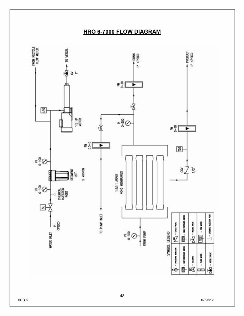
HRO 6-7000 FLOW DIAGRAM
49 HRO 6 07/26/12
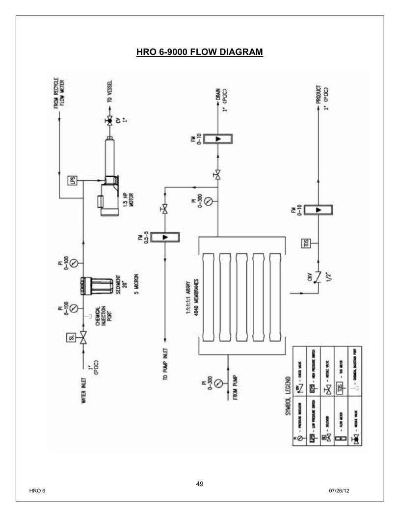
HRO 6-9000 FLOW DIAGRAM
50 HRO 6 07/26/12
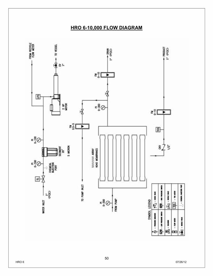
HRO 6-10,000 FLOW DIAGRAM
51 HRO 6 07/26/12
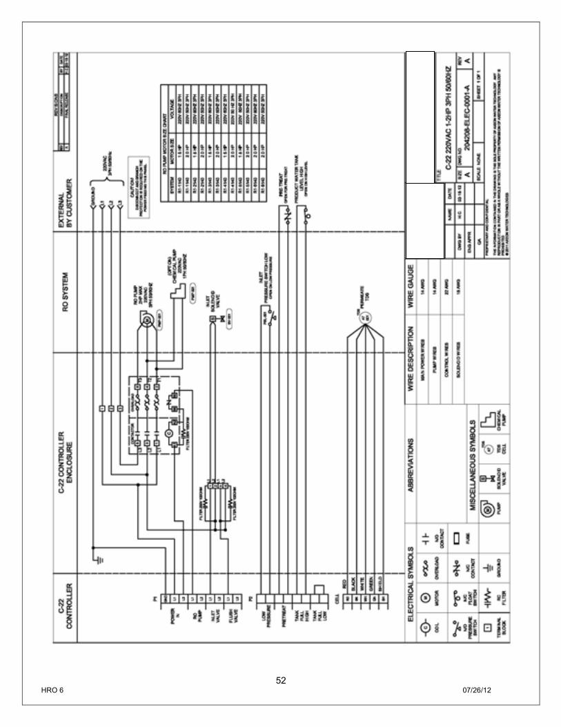
52 HRO 6 07/26/12
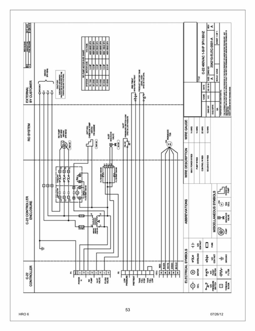
53 HRO 6 07/26/12
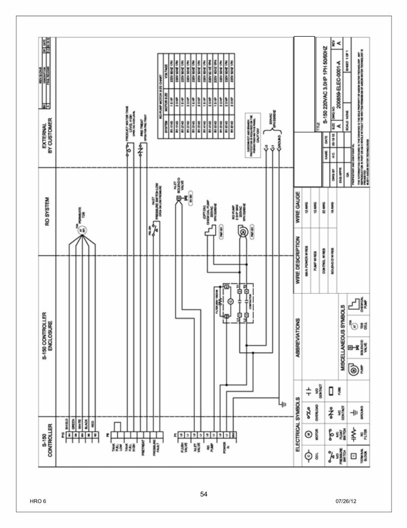
54 HRO 6 07/26/12
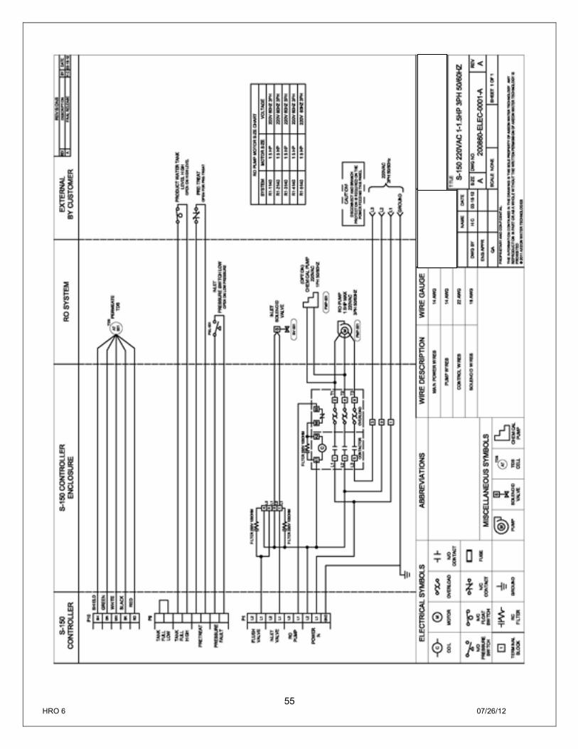
55 HRO 6 07/26/12
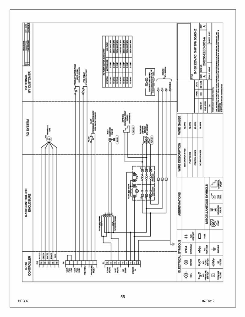
56 HRO 6 07/26/12
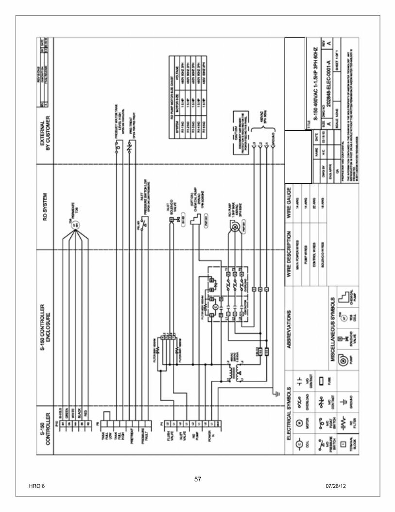
57 HRO 6 07/26/12
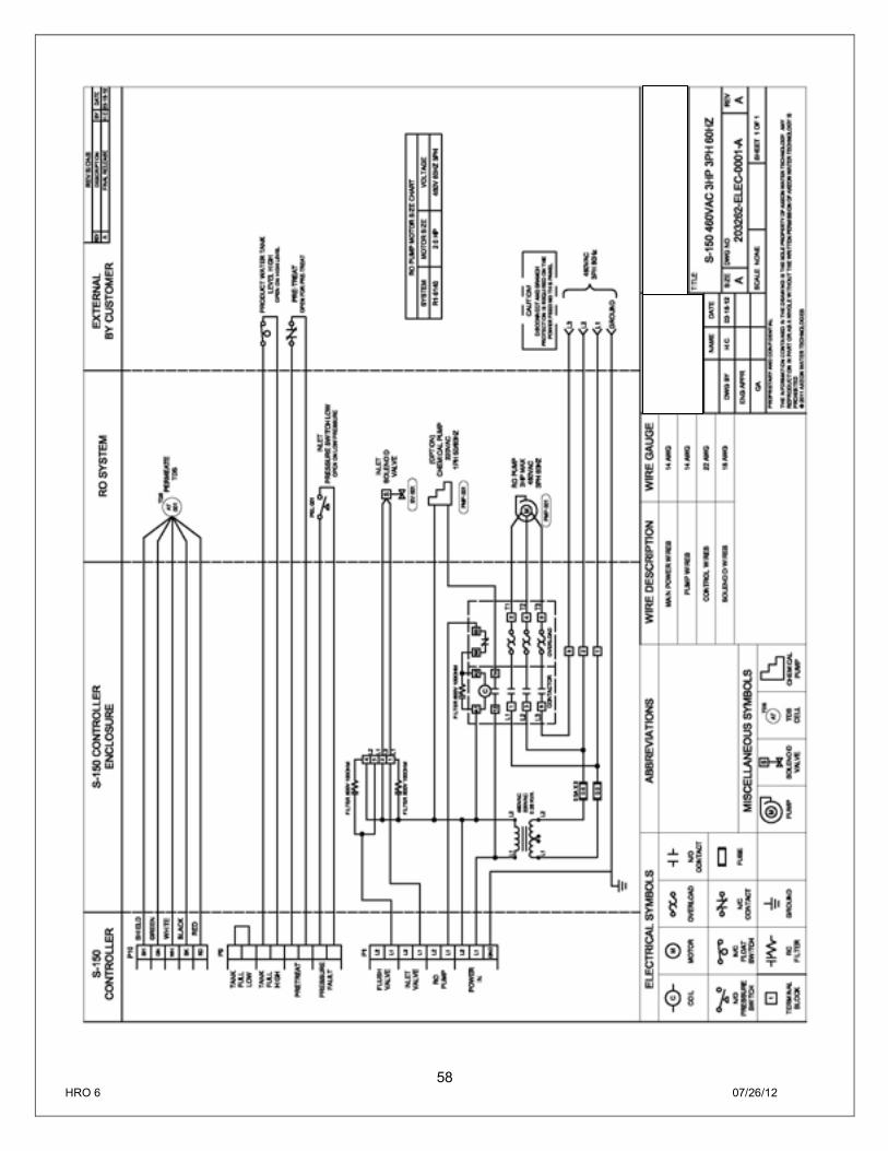
58 HRO 6 07/26/12

59 HRO 6 07/26/12
This Page Intentionally Left Blank