Embed Size (px)
Citation preview

P/N 1011596 Rev. A 05/21
®
Reverse Osmosis System
Owner’s Manual
Models AQ-RO-400 AQ-RO-600
Manufacturing Numbers:9710141 9710142 9710143
www.antunes.com CAUTION: Read all instructions before using the unit.
Original Instructions
®
P/N 1011596 Rev. A 05/212
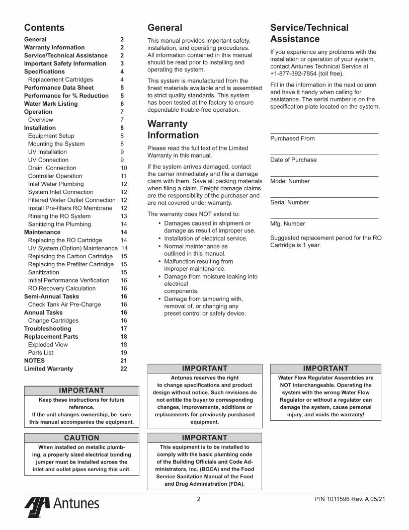
GeneralThis manual provides important safety, installation, and operating procedures. All information contained in this manual should be read prior to installing and operating the system.
This system is manufactured from the finest materials available and is assembled to strict quality standards. This system has been tested at the factory to ensure dependable trouble-free operation.
Warranty InformationPlease read the full text of the Limited Warranty in this manual.
If the system arrives damaged, contact the carrier immediately and file a damage claim with them. Save all packing materials when filing a claim. Freight damage claims are the responsibility of the purchaser and are not covered under warranty.
The warranty does NOT extend to: y Damages caused in shipment or damage as result of improper use.
y Installation of electrical service. y Normal maintenance as outlined in this manual.
y Malfunction resulting from improper maintenance.
y Damage from moisture leaking into electrical components.
y Damage from tampering with, removal of, or changing any preset control or safety device.
IMPORTANTAntunes reserves the right
to change specifications and product design without notice. Such revisions do
not entitle the buyer to corresponding changes, improvements, additions or
replacements for previously purchased equipment.
IMPORTANTKeep these instructions for future
reference. If the unit changes ownership, be sure
this manual accompanies the equipment.
Service/Technical AssistanceIf you experience any problems with the installation or operation of your system, contact Antunes Technical Service at +1-877-392-7854 (toll free).
Fill in the information in the next column and have it handy when calling for assistance. The serial number is on the specification plate located on the system.
Purchased From
Date of Purchase
Model Number
Serial Number
Mfg. Number
Suggested replacement period for the RO Cartridge is 1 year.
IMPORTANTThis equipment is to be installed to
comply with the basic plumbing code of the Building Officials and Code Ad-
ministrators, Inc. (BOCA) and the Food Service Sanitation Manual of the Food
and Drug Administration (FDA).
IMPORTANTWater Flow Regulator Assemblies are NOT interchangeable. Operating the system with the wrong Water Flow
Regulator or without a regulator can damage the system, cause personal
injury, and voids the warranty!
CAUTIONWhen installed on metallic plumb-
ing, a properly sized electrical bonding jumper must be installed across the
inlet and outlet pipes serving this unit.
ContentsGeneral 2Warranty Information 2Service/Technical Assistance 2Important Safety Information 3Specifications 4
Replacement Cartridges 4Performance Data Sheet 5Performance for % Reduction 5Water Mark Listing 6Operation 7
Overview 7Installation 8
Equipment Setup 8Mounting the System 8UV Installation 9UV Connection 9Drain Connection 10Controller Operation 11Inlet Water Plumbing 12System Inlet Connection 12Filtered Water Outlet Connection 12Install Pre-filters RO Membrane 12Rinsing the RO System 13Sanitizing the Plumbing 14
Maintenance 14Replacing the RO Cartridge 14UV System (Option) Maintenance 14Replacing the Carbon Cartridge 15Replacing the Prefilter Cartridge 15Sanitization 15Initial Performance Verification 16RO Recovery Calculation 16
Semi-Annual Tasks 16Check Tank Air Pre-Charge 16
Annual Tasks 16Change Cartridges 16
Troubleshooting 17Replacement Parts 18
Exploded View 18Parts List 19
NOTES 21Limited Warranty 22
®
P/N 1011596 Rev. A 05/21 3
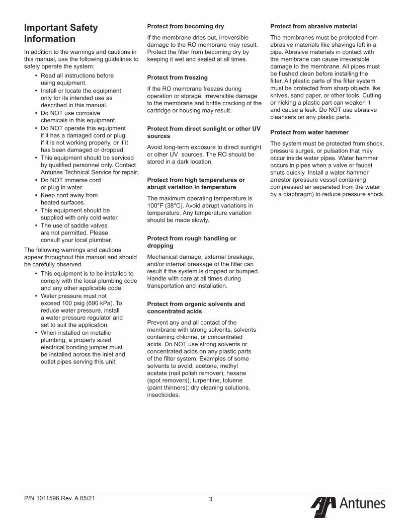
Important Safety InformationIn addition to the warnings and cautions in this manual, use the following guidelines to safely operate the system:
y Read all instructions before using equipment.
y Install or locate the equipment only for its intended use as described in this manual.
y Do NOT use corrosive chemicals in this equipment.
y Do NOT operate this equipment if it has a damaged cord or plug; if it is not working properly, or if it has been damaged or dropped.
y This equipment should be serviced by qualified personnel only. Contact Antunes Technical Service for repair.
y Do NOT immerse cord or plug in water.
y Keep cord away from heated surfaces.
y This equipment should be supplied with only cold water.
y The use of saddle valves are not permitted. Please consult your local plumber.
The following warnings and cautions appear throughout this manual and should be carefully observed.
y This equipment is to be installed to comply with the local plumbing code and any other applicable code.
y Water pressure must not exceed 100 psig (690 kPa). To reduce water pressure, install a water pressure regulator and set to suit the application.
y When installed on metallic plumbing, a properly sized electrical bonding jumper must be installed across the inlet and outlet pipes serving this unit.
Protect from becoming dry
If the membrane dries out, irreversible damage to the RO membrane may result. Protect the filter from becoming dry by keeping it wet and sealed at all times.
Protect from freezing
If the RO membrane freezes during operation or storage, irreversible damage to the membrane and brittle cracking of the cartridge or housing may result.
Protect from direct sunlight or other UV sources
Avoid long-term exposure to direct sunlight or other UV sources. The RO should be stored in a dark location.
Protect from high temperatures or abrupt variation in temperature
The maximum operating temperature is 100°F (38°C). Avoid abrupt variations in temperature. Any temperature variation should be made slowly.
Protect from rough handling or dropping
Mechanical damage, external breakage, and/or internal breakage of the filter can result if the system is dropped or bumped. Handle with care at all times during transportation and installation.
Protect from organic solvents and concentrated acids
Prevent any and all contact of the membrane with strong solvents, solvents containing chlorine, or concentrated acids. Do NOT use strong solvents or concentrated acids on any plastic parts of the filter system. Examples of some solvents to avoid: acetone, methyl acetate (nail polish remover); hexane (spot removers); turpentine, toluene (paint thinners); dry cleaning solutions, insecticides.
Protect from abrasive material
The membranes must be protected from abrasive materials like shavings left in a pipe. Abrasive materials in contact with the membrane can cause irreversible damage to the membrane. All pipes must be flushed clean before installing the filter. All plastic parts of the filter system must be protected from sharp objects like knives, sand paper, or other tools. Cutting or nicking a plastic part can weaken it and cause a leak. Do NOT use abrasive cleansers on any plastic parts.
Protect from water hammer
The system must be protected from shock, pressure surges, or pulsation that may occur inside water pipes. Water hammer occurs in pipes when a valve or faucet shuts quickly. Install a water hammer arrestor (pressure vessel containing compressed air separated from the water by a diaphragm) to reduce pressure shock.
®
P/N 1011596 Rev. A 05/214
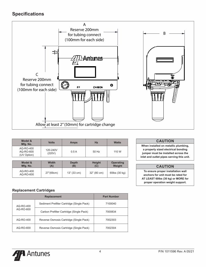
Specifications
Model & Mfg. No.
Width (A)
Depth (B)
Height (C)
Operating Weight
AQ-RO-400 AQ-RO-600 27”(69cm) 13” (33 cm) 32” (80 cm) 65lbs (30 kg)
Model & Mfg. No. Volts Amps Hz Watts
AQ-RO-400 AQ-RO-600 (UV Option)
120-240V (220V) 0.5 A 50 Hz 110 W
Replacement Part Number
AQ-RO-400 AQ-RO-600
Sediment Prefilter Cartridge (Single Pack) 7100040
Carbon Prefilter Cartridge (Single Pack) 7000834
AQ-RO-400 Reverse Osmosis Cartridge (Single Pack) 7002303
AQ-RO-600 Reverse Osmosis Cartridge (Single Pack) 7002304
Replacement Cartridges
CAUTIONWhen installed on metallic plumbing,
a properly sized electrical bonding jumper must be installed across the
inlet and outlet pipes serving this unit.
CAUTIONTo ensure proper installation wall anchors for unit must be rated for
AT LEAST 60lbs (30 kg) or MORE for proper operation weight support.
AReserve 200mm
for tubing connect(100mm for each side)
CReserve 200mm
for tubing connect(100mm for each side)
B
Allow at least 2” (50mm) for cartridge change
®
P/N 1011596 Rev. A 05/21 5
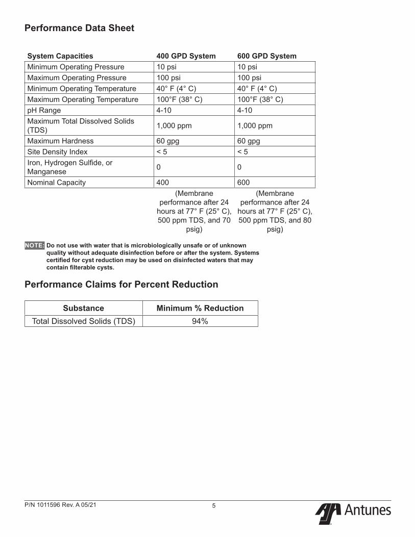
System Capacities 400 GPD System 600 GPD SystemMinimum Operating Pressure 10 psi 10 psiMaximum Operating Pressure 100 psi 100 psiMinimum Operating Temperature 40° F (4° C) 40° F (4° C)Maximum Operating Temperature 100°F (38° C) 100°F (38° C)pH Range 4-10 4-10Maximum Total Dissolved Solids (TDS) 1,000 ppm 1,000 ppm
Maximum Hardness 60 gpg 60 gpgSite Density Index < 5 < 5Iron, Hydrogen Sulfide, or Manganese 0 0
Nominal Capacity 400 600(Membrane
performance after 24 hours at 77° F (25° C), 500 ppm TDS, and 70
psig)
(Membrane performance after 24
hours at 77° F (25° C), 500 ppm TDS, and 80
psig)
Performance Claims for Percent Reduction
Substance Minimum % ReductionTotal Dissolved Solids (TDS) 94%
NOTE: Do not use with water that is microbiologically unsafe or of unknown quality without adequate disinfection before or after the system. Systems certified for cyst reduction may be used on disinfected waters that may contain filterable cysts.
Performance Data Sheet
®
P/N 1011596 Rev. A 05/216
Water Mark Listing
®
P/N 1011596 Rev. A 05/21 7
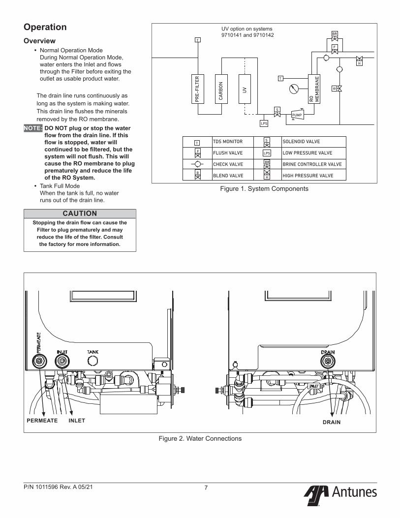
OperationOverview
y Normal Operation Mode During Normal Operation Mode, water enters the Inlet and flows through the Filter before exiting the outlet as usable product water.
The drain line runs continuously as long as the system is making water. This drain line flushes the minerals removed by the RO membrane.
NOTE: DO NOT plug or stop the water flow from the drain line. If this flow is stopped, water will continued to be filtered, but the system will not flush. This will cause the RO membrane to plug prematurely and reduce the life of the RO System.
y Tank Full Mode When the tank is full, no water runs out of the drain line.
CAUTIONStopping the drain flow can cause the
Filter to plug prematurely and may reduce the life of the filter. Consult the factory for more information.
Figure 1. System Components
Figure 2. Water Connections
TDS MONITOR
FLUSH VALVE
CHECK VALVE
BLEND VALVE
SOLENOID VALVE
LOW PRESSURE VALVE
BRINE CONTROLLER VALVE
HIGH PRESSURE VALVE
T
T
T
F
B
S
H
BR
F
B
PUMP
S
H
BR
LPS
LPS
PRE-
FILT
ER
CAR
BO
N
UV
RO
M
EMB
RA
NE
PERMEATE INLET DRAIN
UV option on systems 9710141 and 9710142
®
P/N 1011596 Rev. A 05/218
Installation1. Open the large box. It should
contain:a. Plate-Mounted RO Systemb. Prefilter Cartridgec. Prefilter Carbon Cartridged. RO Cartridgee. Owner’s Manual
NOTE: If any parts are damage, contact Antunes Technical Service IMMEDIATELY at: +1-877-392-7854 (toll free).
2. Remove all packing materials and protective coverings from the system and bracket.
3. A tank is not included with the RO system. The tank must be sourced separately.
Equipment SetupPlumbingNOTE: The system must be connected
to the COLD water line. Do NOT connect the system to the hot water line.
The RO system uses the following connections:
Connection DescriptionSystem Inlet 3/8” OD Tube
System Outlet (Product Water) 1/4” OD Tube
Drain 1/4” OD Tube
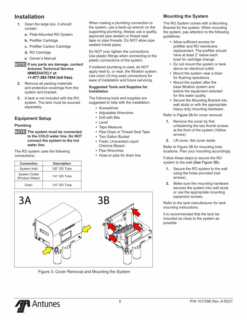
Figure 3. Cover Removal and Mounting the System
When making a plumbing connection to the system, use a back-up wrench on the supporting plumbing. Always use a quality, approved pipe sealant or thread seal tape on pipe threads. Do NOT allow pipe sealant inside pipes.
Do NOT over tighten the connections. Use plastic fittings when connecting to the plastic connections of the system.
If soldered plumbing is used, do NOT apply heat to, or near, the filtration system. Use union (O-ring seal) connections for ease of installation and future servicing.
Suggested Tools and Supplies for Installation
The following tools and supplies are suggested to help with the installation:
y Screwdriver y Adjustable Wrenches y Drill with Bits y Level y Tape Measure y Pipe Dope or Thread Seal Tape y Two Gallon Bucket y Fresh, Unscented Liquid Chlorine Bleach
y Pipe Wrenches y Hose or pipe for drain line
Mounting the SystemThe RO System comes with a Mounting Bracket for the system. When mounting the system, pay attention to the following guidelines:
y Allow sufficient access for prefilter and RO membrane replacement. The prefilter should have at least 2” below each bowl for cartridge change.
y Do not mount the system or tank above an electrical outlet.
y Mount the system near a drain for flushing operations.
y Mount the system after the base filtration system and before the equipment selected for this water quality.
y Secure the Mounting Bracket into wall studs or with the appropriate heavy duty mounting hardware.
Refer to Figure 3A for cover removal.
1. Remove the cover by first unfastening the two thumb screws at the front of the system (Yellow arrows).
2. Lift cover. Set cover aside.
Refer to Figure 3B for mounting hole locations. Plan your mounting accordingly.
Follow these steps to secure the RO system to the wall (See Figure 3B):
1. Secure the RO system to the wall using the holes provided (red arrows).
2. Make sure the mounting hardware secures the system into wall studs or use the appropriate mounting expansion screws.
Refer to the tank manufacturer for tank mounting instructions.
It is recommended that the tank be mounted as close to the system as possible.
3A 3B
®
P/N 1011596 Rev. A 05/21 9
UV Installation(Option on systems 9710141 and 9710142)NOTE: The UV must be connected into
the plumbing circle, otherwise the water will come out of the system.
WARNING: The UV light given off by the UV bulb can cause serious burns to unprotected eyes and skin. Do NOT perform any maintenance tasks with the bulb plugged in and powered on.
Pay attention to the following guidelines when working with the UV light:
y Never look directly at an illuminated UV lamp
y Always unplug the UV unit before performing any work on the UV bulb or disinfection system
y Never operate the UV bulb outside of the UV housing
It is recommended that the UV light be mounted below the filtration system horizontally.
The UV light comes with two clips for mounting and a power supply.
1. Refer to Figure 4 and 5, mount the clips beside the filtration system with the appropriate mounting hardware.
NOTE: Pay attention to the distance between the two clips, it is recommended that the distance be approximately 2/3 the length of the UV light.
2. Take out the UV bulb and the power supply from the box.
3. Insert the bulb into the UV housing. Only keep the end of the bulb out.
4. Connect the bulb and the power supply.
5. Attach the power supply to the UV housing.
6. Place the UV housing onto the clips properly, refer to Figure 5.
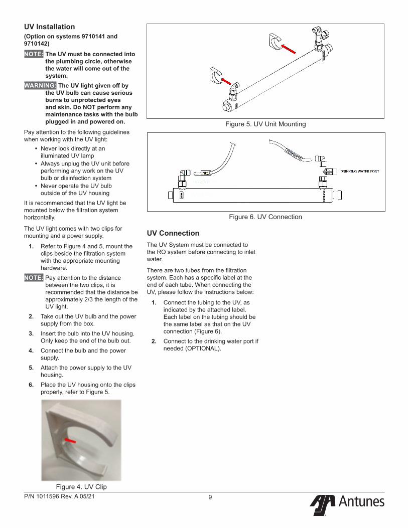
Figure 4. UV Clip
Figure 5. UV Unit Mounting
Figure 6. UV Connection
UV ConnectionThe UV System must be connected to the RO system before connecting to inlet water.
There are two tubes from the filtration system. Each has a specific label at the end of each tube. When connecting the UV, please follow the instructions below:
1. Connect the tubing to the UV, as indicated by the attached label. Each label on the tubing should be the same label as that on the UV connection (Figure 6).
2. Connect to the drinking water port if needed (OPTIONAL).
®
P/N 1011596 Rev. A 05/2110
Drain ConnectionThe drain is for flushing particle buildup out of the system during operation.
Install a sufficient length of 3/8” OD tubing (not supplied) from the drain outlet on top of the RO system to the drain.
When connecting the drain hose, pay attention to the following guidelines:
y The drain line plumbing must be able support the flow rate when the system operates.
y The drain line leading out of the system must be as short as possible and slope downwards without any kinks or loops.
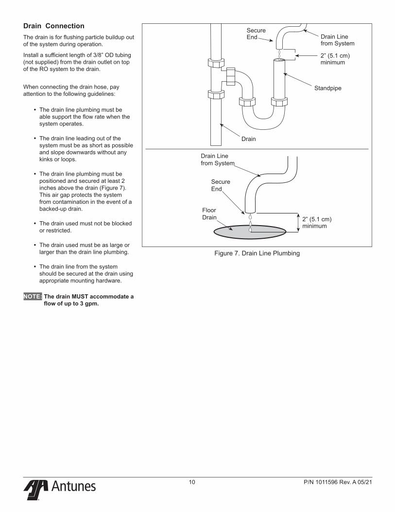
y The drain line plumbing must be positioned and secured at least 2 inches above the drain (Figure 7). This air gap protects the system from contamination in the event of a backed-up drain.
y The drain used must not be blocked or restricted.
y The drain used must be as large or larger than the drain line plumbing.
y The drain line from the system should be secured at the drain using appropriate mounting hardware.
NOTE: The drain MUST accommodate a flow of up to 3 gpm.
2” (5.1 cm) minimum
2” (5.1 cm) minimum
Floor Drain
Secure End
Drain Line from System
Drain Line from System
Secure End
Drain
Standpipe
Figure 7. Drain Line Plumbing
®
P/N 1011596 Rev. A 05/21 11
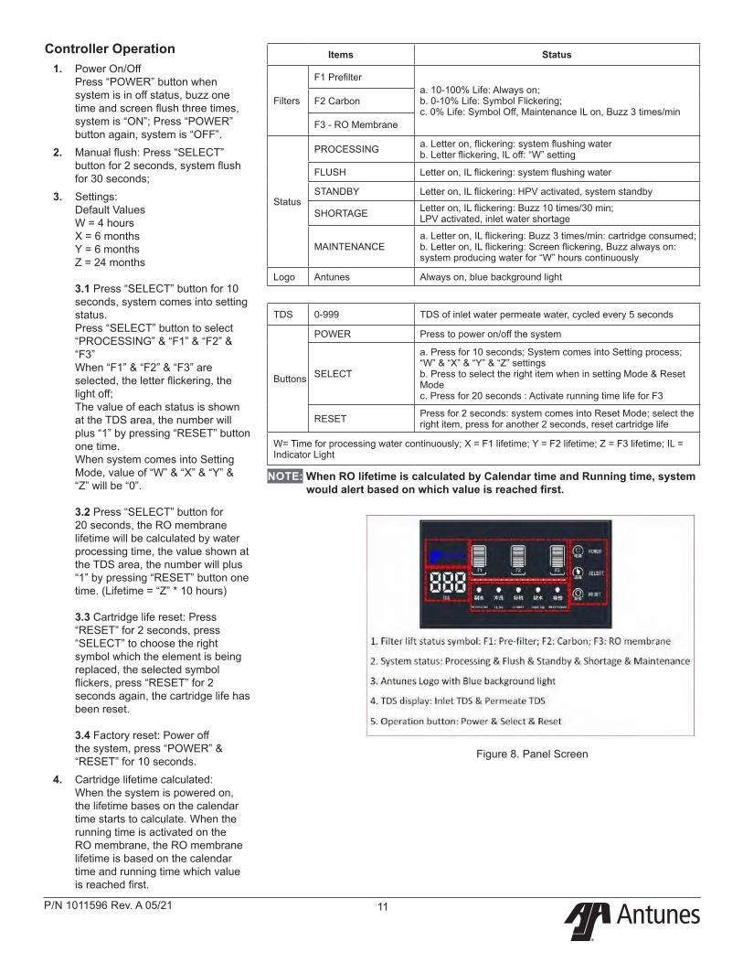
Figure 8. Panel Screen
Controller Operation1. Power On/Off
Press “POWER” button when system is in off status, buzz one time and screen flush three times, system is “ON”; Press “POWER” button again, system is “OFF”.
2. Manual flush: Press “SELECT” button for 2 seconds, system flush for 30 seconds;
3. Settings: Default Values W = 4 hours X = 6 months Y = 6 months Z = 24 months 3.1 Press “SELECT” button for 10 seconds, system comes into setting status. Press “SELECT” button to select “PROCESSING” & “F1” & “F2” & “F3” When “F1” & “F2” & “F3” are selected, the letter flickering, the light off; The value of each status is shown at the TDS area, the number will plus “1” by pressing “RESET” button one time. When system comes into Setting Mode, value of “W” & “X” & “Y” & “Z” will be “0”. 3.2 Press “SELECT” button for 20 seconds, the RO membrane lifetime will be calculated by water processing time, the value shown at the TDS area, the number will plus “1” by pressing “RESET” button one time. (Lifetime = “Z” * 10 hours) 3.3 Cartridge life reset: Press “RESET” for 2 seconds, press “SELECT” to choose the right symbol which the element is being replaced, the selected symbol flickers, press “RESET” for 2 seconds again, the cartridge life has been reset. 3.4 Factory reset: Power off the system, press “POWER” & “RESET” for 10 seconds.
4. Cartridge lifetime calculated: When the system is powered on, the lifetime bases on the calendar time starts to calculate. When the running time is activated on the RO membrane, the RO membrane lifetime is based on the calendar time and running time which value is reached first.
Items Status
Filters
F1 Prefiltera. 10-100% Life: Always on; b. 0-10% Life: Symbol Flickering; c. 0% Life: Symbol Off, Maintenance IL on, Buzz 3 times/min
F2 Carbon
F3 - RO Membrane
Status
PROCESSING a. Letter on, flickering: system flushing water b. Letter flickering, IL off: “W” setting
FLUSH Letter on, IL flickering: system flushing water
STANDBY Letter on, IL flickering: HPV activated, system standby
SHORTAGE Letter on, IL flickering: Buzz 10 times/30 min; LPV activated, inlet water shortage
MAINTENANCEa. Letter on, IL flickering: Buzz 3 times/min: cartridge consumed; b. Letter on, IL flickering: Screen flickering, Buzz always on: system producing water for “W” hours continuously
Logo Antunes Always on, blue background light
TDS 0-999 TDS of inlet water permeate water, cycled every 5 seconds
Buttons
POWER Press to power on/off the system
SELECT
a. Press for 10 seconds; System comes into Setting process; “W” & “X” & “Y” & “Z” settings b. Press to select the right item when in setting Mode & Reset Mode c. Press for 20 seconds : Activate running time life for F3
RESET Press for 2 seconds: system comes into Reset Mode; select the right item, press for another 2 seconds, reset cartridge life
W= Time for processing water continuously; X = F1 lifetime; Y = F2 lifetime; Z = F3 lifetime; IL = Indicator Light
NOTE: When RO lifetime is calculated by Calendar time and Running time, system would alert based on which value is reached first.
®
P/N 1011596 Rev. A 05/2112
Inlet Water PlumbingFiltered water from a base filtration system should be connected to the inlet of the RO System.
Connect Beverage hose (not supplied) to the outlet of the base filtration system.
Before connecting to the RO System inlet, the plumbing from the base filtration system must be flushed clear of all debris. Hold a bucket at the inlet water line and slowly open the base filtration water valve. Allow the plumbing to flush until all debris is removed.
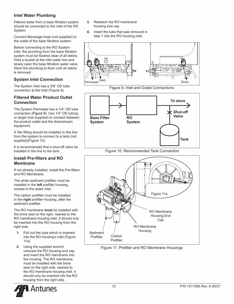
System Inlet ConnectionThe System Inlet has a 3/8” OD tube connection at the Inlet (Figure 9).
Filtered Water Product Outlet ConnectionThe System Permeate has a 1/4” OD tube connection (Figure 9). Use 1/4” OD tubing, or larger (not supplied) to connect between the product outlet and the downstream equipment.
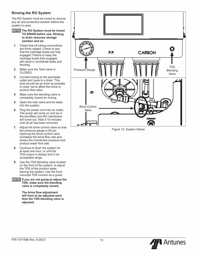
A Tee fitting should be installed in this line from the system to connect to a tank (not supplied)(Figure 10).
It is recommended that a shut-off valve be installed in the line to the tank.
Install Pre-filters and RO MembraneIf not already installed, install the Pre-filters and RO Membrane.
The white sediment prefilter must be installed in the left prefilter housing, closest to the water inlet.
The carbon prefilter must be installed in the right prefilter housing, after the sediment prefilter.
The RO membrane must be installed with the brine seal on the right, nearest to the RO membrane housing inlet. It should only be inserted into the RO housing from the right side.
1. Pull out the tube which is inserted into the RO housing’s inlet (Figure 11a)
2. Using the supplied wrench, unscrew the RO housing end cap and insert the RO membrane into the housing. The RO membrane must be installed with the brine seal on the right side, nearest to the RO membrane housing inlet. It should only be inserted into the RO housing from the right side.
Figure 10. Recommended Tank Connection
Figure 11. Prefilter and RO Membrane Housings
Base Filter System
RO System
To store
Shut-off Valve
Tank
Figure 9. Inlet and Outlet ConnectionsPermeate Inlet Drain
3. Reattach the RO membrane housing end cap.
4. Insert the tube that was removed in step 1 into the RO housing inlet.
Sediment Prefilter Carbon
Prefilter
RO Membrane Housing
RO Membrane Housing End
Cap
Figure 11a
®
P/N 1011596 Rev. A 05/21 13
Rinsing the RO SystemThe RO System must be rinsed to remove any air and protective solution before the system is used.
NOTE: The RO System must be rinsed TO DRAIN before use. Rinsing to drain removes storage solution and air.
1. Check that all tubing connections are firmly seated. Check to see that the cartridge bowls are fully engaged. Failure to keep the cartridge bowls fully engaged will result in accidental leaks and flooding.
2. Make sure the Tank valve is CLOSED.
3. Connect tubing to the permeate outlet and route to a drain. This tube should be as short as possible in order not to affect the brine or product flow rates.
4. Make sure the blending valve is completely closed for rinsing.
5. Open the inlet valve and let water into the system.
6. Plug the power cord into an outlet. The pump will come on and air in the pre-filters and RO membrane will come out. Wait 5-10 minutes until all air has been removed.
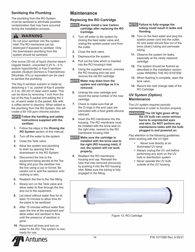
7. Adjust the brine control valve so that the pressure gauge is 80 psi. Opening the brine control valve increases the brine flow rate and lowers the membrane pressure and product water flow rate.
8. Continue to flush the system for at least one hour, or until the TDS output is steady and in an acceptable range.
9. Use the TDS blending valve located on the front of the system, to adjust the TDS of the product water leaving the system. Use the front-mounted TDS monitor as a guide.
NOTE: If you are not going to adjust the TDS, make sure the blending valve is completely closed. The brine flow adjustment will have to be adjusted each time the TDS blending valve is adjusted.
Figure 12. System Valves
Pressure GaugeTDS
Blending Valve
Brine Control Valve
®
P/N 1011596 Rev. A 05/2114
Sanitizing the PlumbingThe plumbing from the RO System must be sanitized to eliminate possible contamination that may have occurred during the installation process.
One ounce (30 ml) of liquid chlorine bleach (regular bleach, unscented 5.25 % - 6 % sodium hypochlorite) or Kay-5 sanitizer solution (Sodium Dichloro-s-Triazinetrione Dihydrate, 6%) or equivalent can be used to sanitize the plumbing.
The Kay-5 sanitizer solution is made by dissolving a 1 oz. packet of Kay-5 powder in 2 oz. (60 ml) of clean warm water. This can be done by removing 1 inch from the top of the Kay-5 packet and adding the 2 oz. of warm water to the packet. Mix with a coffee stirrer to dissolve. When added to the plumbing from the RO System, this will create a 60-100 ppm chlorine solution.
NOTE: Follow the handling and safety instructions supplied with the sanitizer.
1. Follow the steps in the Rinsing the RO System section of this manual.
2. Turn off the water to the system.3. Close the Tank valve.4. Allow the system and plumbing
to drain by opening the line downstream to the RO System.
5. Disconnect the line to the equipment being served at the Tee fitting and pour the sanitizer into the line using a cup or funnel. Be careful not to spill the sanitizer onto clothing or skin.
6. Reattach the line to the Tee fitting.7. Slowly turn on the Tank valve and
allow water to flow through the line and out to the equipment.
8. Let stand without water flow for at least 15 minutes to allow time for the pipes to be sanitized.
9. After 15 minutes without water flow, open the line at the equipment and allow water and sanitizer to flow until the presence of sanitizer is gone.
10. Reconnect all lines and turn on water to the RO. The system is now ready for use.
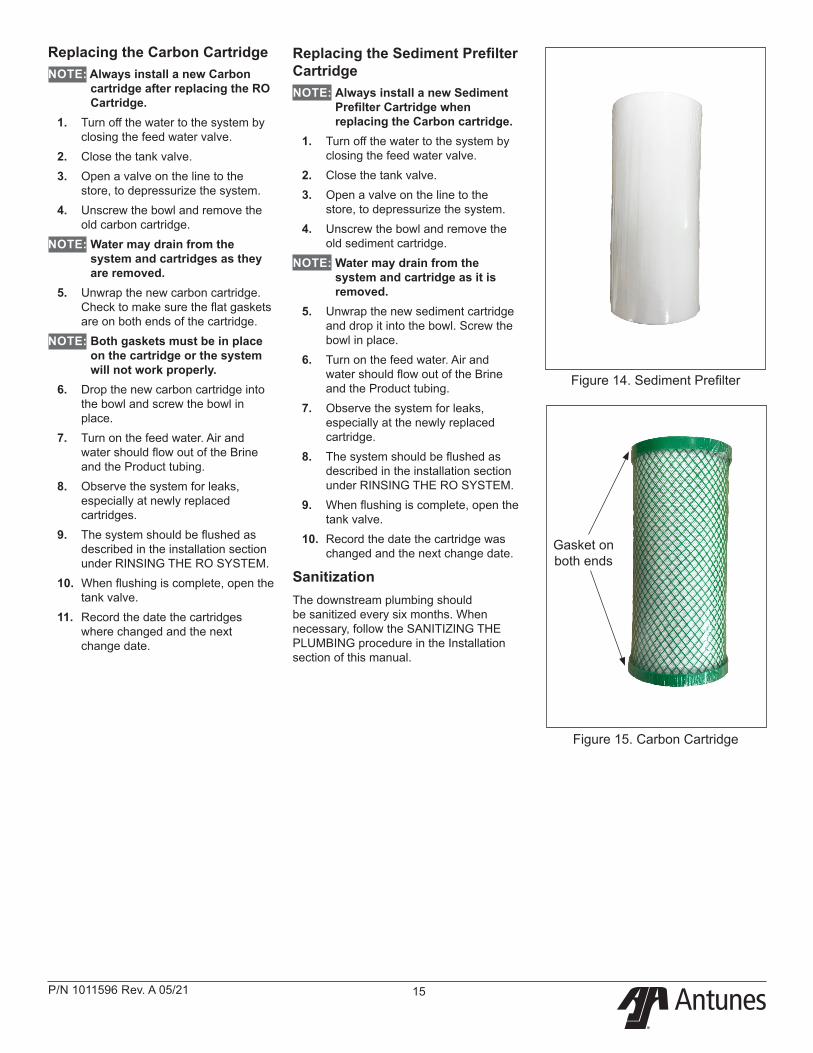
MaintenanceReplacing the RO CartridgeNOTE: Always install a new Carbon
cartridge after replacing the RO Cartridge.
1. Turn off water to the system by closing the feed water valve and unplug the system power cord from the outlet.
2. Close the tank valve.3. Depressurize the system.4. Pull out the tube which is inserted
into the RO housing’s inlet.5. Using the supplied wrench, unscrew
the RO housing end cap and remove the old RO cartridge.
NOTE: Water may drain from the system and cartridge as it is removed.
6. Unwrap the new cartridge and record the serial number of the new cartridge.
7. Check to make sure that all the O-rings in the end caps are lubricated with a food grade silicone lubricant.
8. Insert the RO membrane into the housing. The RO membrane must be installed with the brine seal on the right side, nearest to the RO membrane housing inlet.
NOTE: Make sure the cartridge is installed with the brine seal to the right (RO housing inlet), if not, the system will not work properly.
9. Reattach the RO membrane housing end cap. Reinstall the tube that was removed previously by pushing it into the RO housing inlet. Make sure the tubing is fully engaged in the fitting.
Figure 13. RO Cartridge
NOTE: Failure to fully engage the tubing could result in leaks and flooding.
10. Turn on the feed water and plug the system power cord into the outlet. Air and water should flow out of the brine (drain) tubing and permeate tubing.
11. Observe the system for leaks, especially at the newly replaced cartridge.
12. The system should be flushed as described in the installation section under RINSING THE RO SYSTEM.
13. When flushing is complete, open the tank valve.
14. Record the next change date of the RO Cartridge.
UV System (Option) MaintenanceThe UV system requires periodic maintenance in order to function properly.
WARNING: The UV light given off by the UV bulb can cause serious burns to unprotected eyes and skin. Do NOT perform any maintenance tasks with the bulb plugged in and powered on.
Pay attention to the following guidelines when working with the UV light:
y Never look directly at an illuminated UV lamp
y Always unplug the UV unit before performing any work on the UV bulb or disinfection system
y Never operate the UV bulb outside of the UV housing
WARNINGDo not pour sanitizer into the system inlet! The RO membrane can be destroyed if exposed to sanitizer. Only the downstream plumbing from the system should be sanitized.
®
P/N 1011596 Rev. A 05/21 15
Replacing the Carbon CartridgeNOTE: Always install a new Carbon
cartridge after replacing the RO Cartridge.
1. Turn off the water to the system by closing the feed water valve.
2. Close the tank valve.3. Open a valve on the line to the
store, to depressurize the system.4. Unscrew the bowl and remove the
old carbon cartridge.NOTE: Water may drain from the
system and cartridges as they are removed.
5. Unwrap the new carbon cartridge. Check to make sure the flat gaskets are on both ends of the cartridge.
NOTE: Both gaskets must be in place on the cartridge or the system will not work properly.
6. Drop the new carbon cartridge into the bowl and screw the bowl in place.
7. Turn on the feed water. Air and water should flow out of the Brine and the Product tubing.
8. Observe the system for leaks, especially at newly replaced cartridges.
9. The system should be flushed as described in the installation section under RINSING THE RO SYSTEM.
10. When flushing is complete, open the tank valve.
11. Record the date the cartridges where changed and the next change date.
Replacing the Sediment Prefilter CartridgeNOTE: Always install a new Sediment
Prefilter Cartridge when replacing the Carbon cartridge.
1. Turn off the water to the system by closing the feed water valve.
2. Close the tank valve.3. Open a valve on the line to the
store, to depressurize the system.4. Unscrew the bowl and remove the
old sediment cartridge.NOTE: Water may drain from the
system and cartridge as it is removed.
5. Unwrap the new sediment cartridge and drop it into the bowl. Screw the bowl in place.
6. Turn on the feed water. Air and water should flow out of the Brine and the Product tubing.
7. Observe the system for leaks, especially at the newly replaced cartridge.
8. The system should be flushed as described in the installation section under RINSING THE RO SYSTEM.
9. When flushing is complete, open the tank valve.
10. Record the date the cartridge was changed and the next change date.
SanitizationThe downstream plumbing should be sanitized every six months. When necessary, follow the SANITIZING THE PLUMBING procedure in the Installation section of this manual.
Gasket on both ends
Figure 14. Sediment Prefilter
Figure 15. Carbon Cartridge
®
P/N 1011596 Rev. A 05/2116
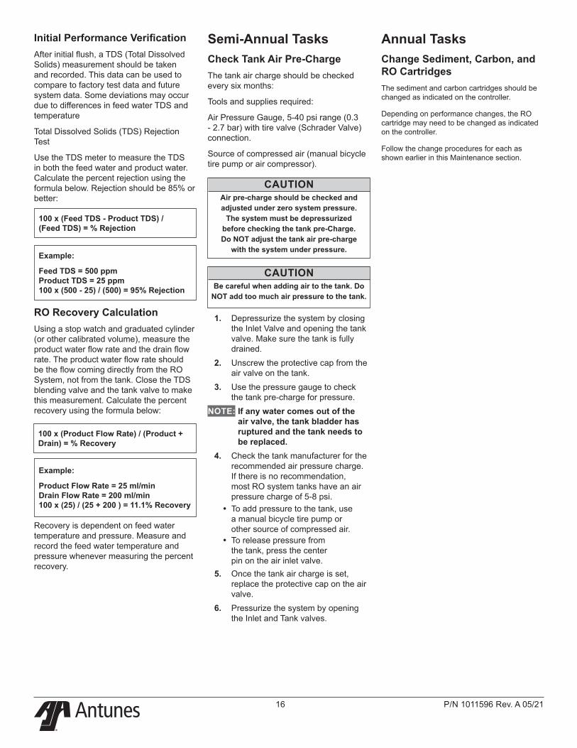
Initial Performance VerificationAfter initial flush, a TDS (Total Dissolved Solids) measurement should be taken and recorded. This data can be used to compare to factory test data and future system data. Some deviations may occur due to differences in feed water TDS and temperature
Total Dissolved Solids (TDS) Rejection Test
Use the TDS meter to measure the TDS in both the feed water and product water. Calculate the percent rejection using the formula below. Rejection should be 85% or better:
100 x (Feed TDS - Product TDS) / (Feed TDS) = % Rejection
Example:
Feed TDS = 500 ppm Product TDS = 25 ppm 100 x (500 - 25) / (500) = 95% Rejection
RO Recovery CalculationUsing a stop watch and graduated cylinder (or other calibrated volume), measure the product water flow rate and the drain flow rate. The product water flow rate should be the flow coming directly from the RO System, not from the tank. Close the TDS blending valve and the tank valve to make this measurement. Calculate the percent recovery using the formula below:
100 x (Product Flow Rate) / (Product + Drain) = % Recovery
Example:
Product Flow Rate = 25 ml/min Drain Flow Rate = 200 ml/min 100 x (25) / (25 + 200 ) = 11.1% Recovery
Recovery is dependent on feed water temperature and pressure. Measure and record the feed water temperature and pressure whenever measuring the percent recovery.
Semi-Annual TasksCheck Tank Air Pre-ChargeThe tank air charge should be checked every six months:
Tools and supplies required:
Air Pressure Gauge, 5-40 psi range (0.3 - 2.7 bar) with tire valve (Schrader Valve) connection.
Source of compressed air (manual bicycle tire pump or air compressor).
CAUTIONAir pre-charge should be checked and adjusted under zero system pressure.
The system must be depressurized before checking the tank pre-Charge. Do NOT adjust the tank air pre-charge
with the system under pressure.
CAUTIONBe careful when adding air to the tank. Do
NOT add too much air pressure to the tank.
1. Depressurize the system by closing the Inlet Valve and opening the tank valve. Make sure the tank is fully drained.
2. Unscrew the protective cap from the air valve on the tank.
3. Use the pressure gauge to check the tank pre-charge for pressure.
NOTE: If any water comes out of the air valve, the tank bladder has ruptured and the tank needs to be replaced.
4. Check the tank manufacturer for the recommended air pressure charge. If there is no recommendation, most RO system tanks have an air pressure charge of 5-8 psi.
y To add pressure to the tank, use a manual bicycle tire pump or other source of compressed air.
y To release pressure from the tank, press the center pin on the air inlet valve.
5. Once the tank air charge is set, replace the protective cap on the air valve.
6. Pressurize the system by opening the Inlet and Tank valves.
Annual TasksChange Sediment, Carbon, and RO CartridgesThe sediment and carbon cartridges should be changed as indicated on the controller.
Depending on performance changes, the RO cartridge may need to be changed as indicated on the controller.
Follow the change procedures for each as shown earlier in this Maintenance section.
®
P/N 1011596 Rev. A 05/21 17
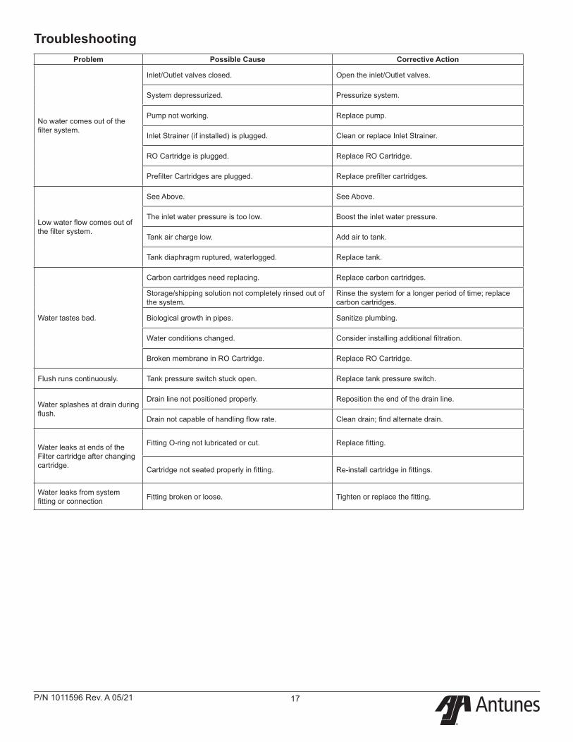
Problem Possible Cause Corrective Action
No water comes out of the filter system.
Inlet/Outlet valves closed. Open the inlet/Outlet valves.
System depressurized. Pressurize system.
Pump not working. Replace pump.
Inlet Strainer (if installed) is plugged. Clean or replace Inlet Strainer.
RO Cartridge is plugged. Replace RO Cartridge.
Prefilter Cartridges are plugged. Replace prefilter cartridges.
Low water flow comes out of the filter system.
See Above. See Above.
The inlet water pressure is too low. Boost the inlet water pressure.
Tank air charge low. Add air to tank.
Tank diaphragm ruptured, waterlogged. Replace tank.
Water tastes bad.
Carbon cartridges need replacing. Replace carbon cartridges.
Storage/shipping solution not completely rinsed out of the system.
Rinse the system for a longer period of time; replace carbon cartridges.
Biological growth in pipes. Sanitize plumbing.
Water conditions changed. Consider installing additional filtration.
Broken membrane in RO Cartridge. Replace RO Cartridge.
Flush runs continuously. Tank pressure switch stuck open. Replace tank pressure switch.
Water splashes at drain during flush.
Drain line not positioned properly. Reposition the end of the drain line.
Drain not capable of handling flow rate. Clean drain; find alternate drain.
Water leaks at ends of the Filter cartridge after changing cartridge.
Fitting O-ring not lubricated or cut. Replace fitting.
Cartridge not seated properly in fitting. Re-install cartridge in fittings.
Water leaks from system fitting or connection Fitting broken or loose. Tighten or replace the fitting.
Troubleshooting
®
P/N 1011596 Rev. A 05/2118
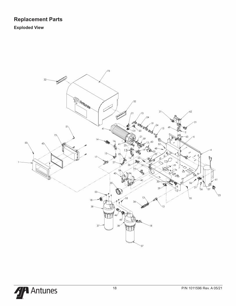
Replacement Parts Exploded View
73
32
32
1
43
51
72
62
21
2113
24
1924
13
21
41
41
61
4
23
5621
57
56
37
18
13
36
13
37
18
46
45
53
53
35
4054
16
22
48
52
1416
1317
27
2516
13
2
49
63 6
2031
50
29
30
15
1626
55
60
2159
1920
1325
40
54
55
38
38
ITEM NO. PART NUMBER DESCRIPTION QTY.
1 0510392 BRACKET, CTRL MOUNT 1
2 0510393 BRACKET, SV MOUNT 1
3 0510394 BRACKET, RO CLAMP 2
4 0510395 BRACKET, BACK 1
5 0510396 BRACKET, COVER 1
6 0701123 ADAPTER, DC 24V 5.0A 1
7 0701134 WIRE SET, RO CONTROLLER, 12PIN 1
8 1001081 LABEL, INLET 1
9 1001082 LABEL, PERMEATE 1
10 1002749 LABEL, ANTUNES LOGO 2.86" X 9.97" 1
11 2020147 3/8" TUBING; WHITE[85mm] 14
12 2020150 1/4" TUBING; WHITE[100mm] 9
13 2080181 FITTING, POM, ELB, 3/8" TUBE X 3/8" STEM 7
14 2080217 FITTING, STR, 3/8" X 3/8" TUBE, SHEET MOUNTING 1
15 2080218 FITTING,STR, 1/4" X 1/4" TUBE, SHEET MOUNTING 2
16 2080219 FITTING,ELB, 3/8" X 3/8" TUBE 4
17 2080220 FITTING,T-ADAPTOR, 1/4" TUBE X 3/8" STEM 1
18 2080221 FITTING, ELB, 1/2" NPT X 3/8" TUBE 2
19 2080222 FITTING, T-ADAPTOR, 1/4" TUBE X 3/8" TUBE 2
20 2080223 FITTING, ELB, 1/4" TUBE X 1/4" STEM 2
21 2080224 FITTING, STR, 3/8"NPT X 3/8" TUBE 5
22 2080225 FITTING,T-ADAPTOR, 3/8" TUBE X 3/8" STEM 1
23 2080226 FITTING, ELB, 3/8"NPT X 3/8" TUBE 1
24 2080227 3/8" CHECK VALVE 2
25 2080228 FITTING, SIDE T-STEM, 1/4" 2
26 2080229 FITTING, Y-ADAPTOR, 1/4" TUBE 1
27 2080230 FITTING, ELB, 1/4" X 1/4" TUBE 1
28 2080231 FITTING, STR, 1/4"FNPT X 1/4" TUBE 1
29 2080232 ADJT. FLOW RESTRICTOR, 1/4" TUBE 1
30 2080233 TEE, 1/4" TUBE X 1/4'' STEM 1
31 2080235 FITTING, STR, 1/4" TUBE X 3/8" MNPT 1
32 2100212 HANDLE, POCKET PULL, SNAP-IN 2
33 2140144 TAPE, PIPE THREAD 5
34 2140163 THREAD SEALING COMPOUND, (RECTORSEAL) 4
35 2170201 PRESSURE GAUGE, PANEL MOUNTED 1
36 2170212 BLEND VALVE, 3/8'' TUBE, PANEL MOUNTED 1
37 2180495 BOWL 2
38 2180495 HEAD 2
39 2180495 ORING 2
40 2180772 MOUNTING CLIP, RO HSG, 400/600GPD 2
41 2180779 HOUSING, BOWL AND HEAD, RO, 400/600 GPD 1
42 2180823 GLUE BOX, RO CONTROLLER 1
43 2180824 SUPPORT FRAME, RO CONTROLLER 1
44 2180825 PLASTIC CLIP, M4 x 6.3mm 4
45 2190251 ADAPTOR, TUBE TO 1/2 NPT 1
46 2190252 ADAPTOR, 1/2 STEM 1
47 3060128 STUD, SELF CLINCH, #6-32 X 5/8" 2
48 3060130 NUT,HEX"KEPS" #06-32 STEEL; ZINC PLATED 2
49 3060220 SCREW, M4 X 6MM, SS304 2
50 3080157 SCREW, #8-32 X 3/8" LG PHTRSHD 4
51 3080194 SCREW #8-32 X 3/4, PAN HD. PHIL. ST. STL 4
52 3080223 WASHER, FLAT #8 2
53 3080347 SCREW, 1/16'' - 16 X 1/2'' LG 10
54 3080359 8-32 x .50 LG PH S.S. EPOXY-LOCK PATCH 2
55 3080370 SCREW, THUMB #8-32 X 5/8 KNURLED HEAD 2
56 3100146 NUT, HEX "KEPS" #10-32 4
57 3100157 WASHER, FLAT #10 4
58 3100203 STUD, PEM #10-32 X 7/8" 4
59 4010278 LOW PRESSURE SWITCH, RO, 400/600 GPD 1
60 4010279 HIGH PRESSURE SWITCH, RO, 400/600 GPD 1
61 4040234 PUMP, DIAP, 2.5L/MIN, 3/8 NPTF, 24V 1
62 4040236 VALVE, SOL NC, 3/8'' NPT, SANLIXIN 1
63 4040237 VALVE, SOL NC, 1/4'' TUBE, SANLIXIN 1
64 4060377 CABLE TIE MOUNT W/ ADHESIVE 3
65 4060399 CONTACT BLOCK 1
66 4060399 HOUSING GROMMET 1
67 4060399 HOUSING NUT 1
68 4060399 HOUSING SCREW 1
69 4060399 HOUSING SHELL 1
70 4060399 INSULATOR 1
71 4060399 NUT WASHER 1
72 4070439 RO CONTROLLER, AQ-RO, SUZHOU 1
73 5040238 GASKET, RAW MATERIAL 5
74 TER62-0003 TERM-RECEPT 8
75 TER62-0004 TERM-RECEPT 3/16'' FASTON .135'' MAX 4
76 ter62-0002 TERM-TAB 1/4'' FASTON .135'' MAX 6
®
P/N 1011596 Rev. A 05/21 19
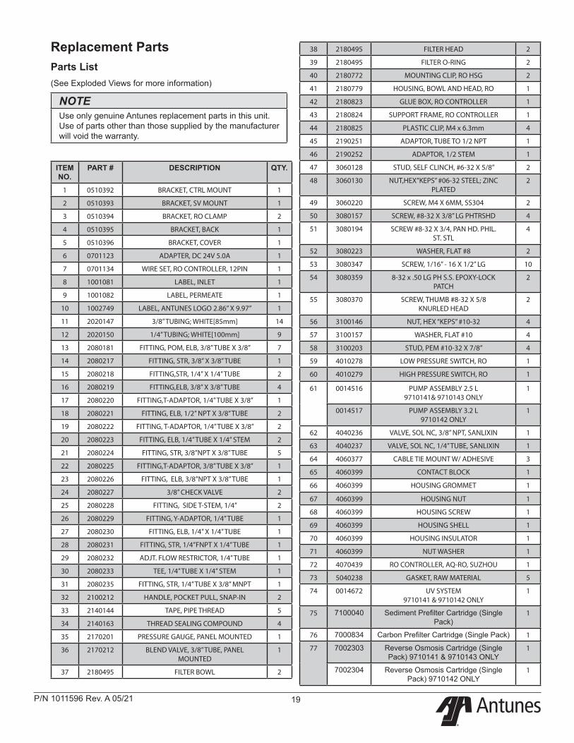
Replacement PartsParts List(See Exploded Views for more information)
NOTEUse only genuine Antunes replacement parts in this unit. Use of parts other than those supplied by the manufacturer will void the warranty.
ITEM NO.
PART # DESCRIPTION QTY.
1 0510392 BRACKET, CTRL MOUNT 1
2 0510393 BRACKET, SV MOUNT 1
3 0510394 BRACKET, RO CLAMP 2
4 0510395 BRACKET, BACK 1
5 0510396 BRACKET, COVER 1
6 0701123 ADAPTER, DC 24V 5.0A 1
7 0701134 WIRE SET, RO CONTROLLER, 12PIN 1
8 1001081 LABEL, INLET 1
9 1001082 LABEL, PERMEATE 1
10 1002749 LABEL, ANTUNES LOGO 2.86” X 9.97” 1
11 2020147 3/8” TUBING; WHITE[85mm] 14
12 2020150 1/4” TUBING; WHITE[100mm] 9
13 2080181 FITTING, POM, ELB, 3/8” TUBE X 3/8” 7
14 2080217 FITTING, STR, 3/8” X 3/8” TUBE 1
15 2080218 FITTING,STR, 1/4” X 1/4” TUBE 2
16 2080219 FITTING,ELB, 3/8” X 3/8” TUBE 4
17 2080220 FITTING,T-ADAPTOR, 1/4” TUBE X 3/8” 1
18 2080221 FITTING, ELB, 1/2” NPT X 3/8” TUBE 2
19 2080222 FITTING, T-ADAPTOR, 1/4” TUBE X 3/8” 2
20 2080223 FITTING, ELB, 1/4” TUBE X 1/4” STEM 2
21 2080224 FITTING, STR, 3/8”NPT X 3/8” TUBE 5
22 2080225 FITTING,T-ADAPTOR, 3/8” TUBE X 3/8” 1
23 2080226 FITTING, ELB, 3/8”NPT X 3/8” TUBE 1
24 2080227 3/8” CHECK VALVE 2
25 2080228 FITTING, SIDE T-STEM, 1/4” 2
26 2080229 FITTING, Y-ADAPTOR, 1/4” TUBE 1
27 2080230 FITTING, ELB, 1/4” X 1/4” TUBE 1
28 2080231 FITTING, STR, 1/4”FNPT X 1/4” TUBE 1
29 2080232 ADJT. FLOW RESTRICTOR, 1/4” TUBE 1
30 2080233 TEE, 1/4” TUBE X 1/4’’ STEM 1
31 2080235 FITTING, STR, 1/4” TUBE X 3/8” MNPT 1
32 2100212 HANDLE, POCKET PULL, SNAP-IN 2
33 2140144 TAPE, PIPE THREAD 5
34 2140163 THREAD SEALING COMPOUND 4
35 2170201 PRESSURE GAUGE, PANEL MOUNTED 1
36 2170212 BLEND VALVE, 3/8’’ TUBE, PANEL MOUNTED
1
37 2180495 FILTER BOWL 2
38 2180495 FILTER HEAD 2
39 2180495 FILTER O-RING 2
40 2180772 MOUNTING CLIP, RO HSG 2
41 2180779 HOUSING, BOWL AND HEAD, RO 1
42 2180823 GLUE BOX, RO CONTROLLER 1
43 2180824 SUPPORT FRAME, RO CONTROLLER 1
44 2180825 PLASTIC CLIP, M4 x 6.3mm 4
45 2190251 ADAPTOR, TUBE TO 1/2 NPT 1
46 2190252 ADAPTOR, 1/2 STEM 1
47 3060128 STUD, SELF CLINCH, #6-32 X 5/8” 2
48 3060130 NUT,HEX”KEPS” #06-32 STEEL; ZINC PLATED
2
49 3060220 SCREW, M4 X 6MM, SS304 2
50 3080157 SCREW, #8-32 X 3/8” LG PHTRSHD 4
51 3080194 SCREW #8-32 X 3/4, PAN HD. PHIL. ST. STL
4
52 3080223 WASHER, FLAT #8 2
53 3080347 SCREW, 1/16’’ - 16 X 1/2’’ LG 10
54 3080359 8-32 x .50 LG PH S.S. EPOXY-LOCK PATCH
2
55 3080370 SCREW, THUMB #8-32 X 5/8 KNURLED HEAD
2
56 3100146 NUT, HEX “KEPS” #10-32 4
57 3100157 WASHER, FLAT #10 4
58 3100203 STUD, PEM #10-32 X 7/8” 4
59 4010278 LOW PRESSURE SWITCH, RO 1
60 4010279 HIGH PRESSURE SWITCH, RO 1
61 0014516 PUMP ASSEMBLY 2.5 L 9710141& 9710143 ONLY
1
0014517 PUMP ASSEMBLY 3.2 L 9710142 ONLY
1
62 4040236 VALVE, SOL NC, 3/8’’ NPT, SANLIXIN 1
63 4040237 VALVE, SOL NC, 1/4’’ TUBE, SANLIXIN 1
64 4060377 CABLE TIE MOUNT W/ ADHESIVE 3
65 4060399 CONTACT BLOCK 1
66 4060399 HOUSING GROMMET 1
67 4060399 HOUSING NUT 1
68 4060399 HOUSING SCREW 1
69 4060399 HOUSING SHELL 1
70 4060399 HOUSING INSULATOR 1
71 4060399 NUT WASHER 1
72 4070439 RO CONTROLLER, AQ-RO, SUZHOU 1
73 5040238 GASKET, RAW MATERIAL 5
74 0014672 UV SYSTEM 9710141 & 9710142 ONLY
1
75 7100040 Sediment Prefilter Cartridge (Single Pack)
1
76 7000834 Carbon Prefilter Cartridge (Single Pack) 1
77 7002303 Reverse Osmosis Cartridge (Single Pack) 9710141 & 9710143 ONLY
1
7002304 Reverse Osmosis Cartridge (Single Pack) 9710142 ONLY
1
®
P/N 1011596 Rev. A 05/2120
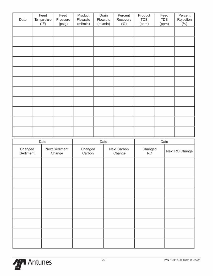
DateFeed
Temperature (°F)
Feed Pressure
(psig)
Product Flowrate (ml/min)
Drain Flowrate (ml/min)
Percent Recovery
(%)
Product TDS
(ppm)
Feed TDS
(ppm)
Percent Rejection
(%)
Date Date Date
Changed Sediment
Next Sediment Change
Changed Carbon
Next Carbon Change
Changed RO Next RO Change
®
P/N 1011596 Rev. A 05/21 21
NOTES
Limited WarrantyEquipment manufactured by Antunes has been constructed of the finest materials available and manufactured to high quality standards. These units are warranted to be free from defects in materials and workmanship for a period of one year from date of purchase under normal use and service, and when installed in accordance with manufacturer’s recommendations*.
*To ensure continued proper operation of the units, follow the maintenance procedure outlined in the Owner’s Manual.
1. This warranty does not cover failures due to improper system installation, defects caused by improper storage or handling prior to placing of the equipment into service. This warranty does not include overtime charges or work done by unauthorized service agencies or personnel. This warranty does not cover normal maintenance, calibration, or regular adjustments as specified in operating and maintenance instructions of this manual, and/or labor involved in moving adjacent objects to gain access to the Equipment.
2. Antunes reserves the right to make changes in design or add any improvements on any product. The right is always reserved to modify equipment because of factors beyond our control and government regulations. Changes to update equipment do not constitute a warranty charge.
3. If shipment is damaged in transit, the purchaser should make a claim directly upon the carrier. Careful inspection should be made of the shipment as soon as it arrives and visible damage should be noted upon the carrier’s documentation. Damage should be reported to the carrier. This damage is not covered under this warranty.
4. THIS WARRANTY IS EXCLUSIVE AND IS IN LIEU OF ALL OTHER WARRANTIES, EXPRESSED OR IMPLIED, INCLUDING ANY IMPLIED WARRANTY OR MERCHANTABILITY OR FITNESS FOR A PARTICULAR PURPOSE, EACH OF WHICH IS HEREBY EXPRESSLY DISCLAIMED. THE REMEDIES DESCRIBED ABOVE ARE EXCLUSIVE AND IN NO EVENT SHALL ANTUNES BE LIABLE FOR SPECIAL CONSEQUENTIAL OR INCIDENTAL DAMAGES FOR THE BREACH OR DELAY IN PERFORMANCE OF THIS WARRANTY.
Prices and specifications are subject to change without notice.