Embed Size (px)
Citation preview

REV. 3 p7.07-v28.f ro_d_mi-r3.doc
REVERSE OSMOSIS SERIES RO /D
INSTRUCTIONS MANUAL INSTRUCTIONS FOR INSTALLATION
OPERATION & MAINTENANCE
WARNING !
The equipment must be used only for the utilizations for which they have been designed, as shown in the technical documentation.
Read carefully this leaflet until the end before starting any operation. Proceed according strictly to all directions included in this manual.
Reverse osmosis systems models RO/D are designed to treat raw water supplied
from municipalities or from well. ANY OTHER APPLICATIONS OF THE EQUIPMENT DIFFERENT THAN THE MENTIONED
ONES IS MADE UNDER THE ONLY RESPONSIBILITY OF THE USER. For any assistance concerning the installations, maintenance or utilization of the equipment
apply the NOBEL Service Center closest to you or directly :
NOBEL S.r.l. via Monfalcone 8 - 20132 Milano tel. +39 02 2827968 FAX +39 02 2610839

REVERSE OSMOSIS SYSTEM RO /D - INSTRUCTIONS MANUAL
s.r.l.Milano - ITALY Page 2 of 19 p7.07 -v28.f ro_d_mi-r3.doc
INDEX 1. Safety ................................................................................................................................3 1.1. General .......................................................................................................................3 1.2. How to displace the unit ..............................................................................................3 1.3. Hydraulics ...................................................................................................................3 1.4. Electrical .....................................................................................................................3 1.5. How to store and delivery............................................................................................4
2. Principles of working..........................................................................................................4 3. Technical characteristics ...................................................................................................4 3.1. Assumed raw water characteristics.............................................................................4 3.2. Technical characteristics (general) .............................................................................5 3.3. Characteristics for each model....................................................................................5
4. Installation .........................................................................................................................5 4.1. Room conditions .........................................................................................................5 4.2. How to remove packaging...........................................................................................6 4.3. How to move and lift the unit.......................................................................................6 4.4. Placing ........................................................................................................................6 4.5. Hydraulics connections ...............................................................................................6 4.6. Electrical wiring connections.......................................................................................7
5. LOGICAL CONTROL PANEL QE......................................................................................8 5.1. Commands & visualizations ........................................................................................8 5.2. Levels..........................................................................................................................9 5.3. External commands ..................................................................................................10 5.4. Hand-driven working .................................................................................................10 5.5. Flushing ....................................................................................................................10 5.6. Conductivity...............................................................................................................11 5.7. Minimum pressure.....................................................................................................11 5.8. Remote alarm............................................................................................................11 5.9. Functions of the display ............................................................................................11 5.10. How to program .....................................................................................................12
6. Service.............................................................................................................................13 6.1. How to insert or replace membranes ........................................................................13 6.2. Starting-up & adjustment...........................................................................................14 6.3. Special instructions of use ........................................................................................15
7. Maintenance ....................................................................................................................16 7.1. Periodical monitoring.................................................................................................16 7.2. How to adjust the min pressure switch PC................................................................16 7.3. Cleaning of the membranes ......................................................................................17 7.4. Disposal ....................................................................................................................17 7.5. Table of chemicals for membranes cleaning.............................................................18
8. Trouble shooting guide ....................................................................................................19 Annex
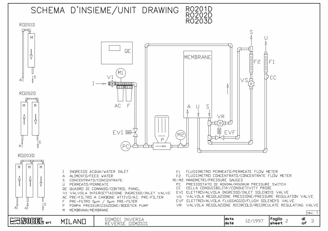
• diagram RO214D RO221D • special instructions filters • diagram RO201D RO202D RO203D • instructions solenoid valves • diagram DIMENSIONS & WEIGHT • special instructions high-pressure pump • wiring diagrams • components list • NOBEL running-test certificate • fitting-out table

REVERSE OSMOSIS SYSTEM RO /D - INSTRUCTIONS MANUAL
s.r.l.Milano - ITALY Page 3 of 19 p7.07 -v28.f ro_d_mi-r3.doc
1. Safety
1.1. General The equipment has been designed and constructed according to D.P.R. n° 459 of 24th July
1996 (regulation for accomplishment of Norms 89/392/CEE, 91/368/CEE, 93/44/CEE and 93/68/CEE regarding the unification of States members laws in so far as machines are concerned).
It has been designed and constructed according to European Norms UNI EN 292-1, UNI EN 292-2, UNI EN 292-2/A1, UNI EN 418, CEI EN 60439-1, CEI EN 60 204-1.
Only authorized and skilled personnel will be allowed to carry out installation, start up as well as routine and planned maintenance.
1.2. How to displace the unit Particular care and attention should be put in during moving and displacing of heavy items, in
order to avoid injuries to persons or damage properties. The heavy components must be lifted and displaced by lifting or hooking them up only by the points and facilities shown on the attached drawings (see § 4.3 page 6) It is strictly recommended to use only proper sized and suitable ropes, chains or hooks. (see DIMENSIONS & WEIGHT diagram).
1.3. Hydraulics
All operations must be performed by and/or under direct supervision of skilled and authorized operators, using proper tools and personal protection devices if required (CE marked), according to safety regulations for working areas. The operators must be aware of the hazards and danger of the chemicals used in the process. In case of leakage of chemicals and/or in case of accident (contact with skin, eyes, etc.) follow strictly the directions mentioned on the safety bulletins of the chemicals themselves. Before any operation of taking out pipes or part of hydraulic system, it is required to release the pressure inside and empty the part of the system.
1.4. Electrical
Before starting any operation on electrical devices, be sure that main power supply is OFF. All operations must be performed by skilled and authorized operators, using proper tools and personal protection devices if required (CE marked), according to safety regulations for working areas. In case of liquid leakage, switch off the main power supply before operation. Before the switching ON, be sure all the parts of the system are perfectly dry. Check that the available electrical power is correct, as shown on technical data, before connection (see § 3.2 page 5 “technical characteristics”). Do not make preliminary wiring connections.

REVERSE OSMOSIS SYSTEM RO /D - INSTRUCTIONS MANUAL
s.r.l.Milano - ITALY Page 4 of 19 p7.07 -v28.f ro_d_mi-r3.doc
1.5. How to store and delivery t = ºC t = ºF humidity rel. notes
• closed rooms 5÷40 41÷104 5÷95% without condensate
• open space 5÷40 41÷104 5÷95% without condensate
protect from sun-light and rain.
• transport 5÷40 41÷104 5÷95% without condensate
protect from sun-light and rain.
2. Principles of working
Osmosis is a natural phenomenon : it is the spontaneous passage of a liquid from a dilute to a more concentrated solution across a semi-permeable membrane. The driving force of the solution through the membrane is its osmotic pressure. Osmotic pressure is function of the concentration of the solution or, in our cases, of the salinity of water.
Reverse Osmosis is the process in which the natural osmotic flow is reversed. Reversal is effected by the application of pressure, greater than the osmotic pressure, to the concentrated solution. Fresh water diffuses through the membrane (practically containing only a small quantities of dissolved salts).
Reverse osmosis process allow the removal of approx. 90÷99 % of dissolved salts and pollutants, if any. The real % removal depends on the kind of membrane used.
The semi-permeable membrane consists of several layers of special fibbers, and can be made of different type and design (spiral wound, hollow fibber, etc.). The word permeate indicates the product water, while the word concentrate indicates the flow of water carried to drain, which contains the dissolved salts removed from the permeate.
3. Technical characteristics
3.1. Assumed raw water characteristics • silt density index (SDI) ≤ 3 • TDS of raw water ppm ≤ 1000 * • raw water temperature min÷max ºC 10÷40 • raw water pressure min÷max bar (kPa) 2.0÷5.0 (200÷500) • bacteria nil • free Chlorine ppm Cl ≤ 0.1 • Iron ppm Fe ≤ 0.1 • silica ppm SiO2 ≤ 10.0 • total hardness : according to the pre-treatment
* max value : according to the construction material used

REVERSE OSMOSIS SYSTEM RO /D - INSTRUCTIONS MANUAL
s.r.l.Milano - ITALY Page 5 of 19 p7.07 -v28.f ro_d_mi-r3.doc
3.2. Technical characteristics (general)
• TDS of treated water ** ≤ 5 % of raw water • power supply V/pH/Hz 230/1/50 • working pressure bar (kPa) approx. 14 (1400) • max allowable pressure bar (kPa) 15 (1500)
** the mentioned percentage is referred to TDS of treated water and of the raw one; it depends
on the chemical-physical characteristics of raw water, the recovery rate and the operating features of the system.
3.3. Characteristics for each model
FILTERS FLOW RATES MODEL VESSEL MEMBRANE FCR
5 µm FCA
ACTIVATED CARBON
PERMEATE l/h **
FEED WATER l/h
POWER
nº nº nº nº at 15ºC MIN MAX kW RO214D 1 1 (2514) 1 1 25 70 150 0.4 RO221D 1 1 (2521) 1 1 45 120 250 0.4 RO201D 1 1 (2540) 1 1 90 240 500 0.4 RO202D 2S 2 (2540) 1 1 180 500 1000 0.6 RO203D 2P-1S 3 (2540) 1 1 270 700 1500 0.6
P: on parallel working S: on serial working.
** treated water quantities, (permeate), as shown, depends on the raw water temperature (feed water) and strictly depends on its chemical-physical characteristics.
4. Installation
4.1. Room conditions These units do not include visible moving or specially noising parts (see also the "noise
monitor chart" attached to the special instructions of high-pressure pump). There are not any points which reaches high temperature.
Room & climate conditions. • room temperature 5÷40ºC (41÷104ºF) • humidity rel. 5÷95 % without condensate • sun-light • protection required • rain, snow etc. • protection required

REVERSE OSMOSIS SYSTEM RO /D - INSTRUCTIONS MANUAL
s.r.l.Milano - ITALY Page 6 of 19 p7.07 -v28.f ro_d_mi-r3.doc
4.2. How to remove packaging The packaging consist of a wooden crate which contains the reverse osmosis system, skid-
mounted. Open the wooden crate removing, first, the cover and, then, the sides. Keep the cards and
everything contained inside the packaging.
4.3. How to move and lift the unit
Some of the pipes of the plant are made in plastic material, hence they can be easily damaged. Do not lift and/or move the unit by any part of the plant. It is suggested to move the unit when it is still protected by its wooden crate. Only for short displacement, catch the unit by the skid using adequate protective gloves. (see DIMENSIONS/WEIGHT diagram)
4.4. Placing Place the unit on a perfectly flat surface.
Follow the directions of the dimensional drawing (DIMENSIONS & WEIGHT DIAGRAM) for the correct placing of the unit, according to the dimensions of the available room and the required room for service and maintenance.
Not any anti-vibration devices are required, hence the unit can be directly placed on floor. .
4.5. Hydraulics connections see DIAGRAM OF THE SYSTEM and DIMENSIONS & WEIGHT DIAGRAM.
• Connect the raw water line (I) to the inlet water fitting upstream of filters manifold, using pipes made in PVC or other suitable materials, with size (Ø) equal or larger than the size of inlet connection (I).
Whether the raw water contains a large quantity of suspended solids, the filters (filtration 5 µm) could be clogged very quickly; in this case a proper pre-filter with filtration of 50 µm, should be provided. According to the characteristics of raw water, the pre-treatment could be required; apply Nobel technical staff for proper suggestion.
• Run the line from the product water outlet fitting (U) to the storage tank, using pipes made in PVC or other suitable materials, with size (Ø) equal or larger than the size of outlet connection (U).
In order to permit the membrane rinsing, it must be arranged the possibility to divert the permeate outlet to the drain.
• Run the line from the drain fitting (S) to a floor drain of a proper size, using pipes made in PVC or other suitable materials, with size (Ø) equal or larger than the size of concentrate connection (S).
THE OUTLET PRODUCT WATER LINE MUST BE COMPLETELY FREE OF
ANY SHRINKAGE - THROTTLING - SHUT OFF VALVE

REVERSE OSMOSIS SYSTEM RO /D - INSTRUCTIONS MANUAL
s.r.l.Milano - ITALY Page 7 of 19 p7.07 -v28.f ro_d_mi-r3.doc
4.6. Electrical wiring connections Run the electrical wiring connections to the terminal board of the control panel, as below
explained. All the connections to the equipment mounted on the skid, have been already made in factory (see WIRING DIAGRAM). • The power supply plant must be made according to the value of voltage, frequency and
adsorption, as stated at paragraph “TECHNICAL CHARACTERISTICS”. • The size of the wires of the electrical power conductors must be selected according to the
max allowable current intensity. • The power supply line must be protected by an automatic differential circuit breaker, with
adequate power and according to applicable law. • It is recommended to use suitable fittings, for the wiring connection, in order not to modify
the protection grade of the control board.
o M1 1 o GND o M1 2 o power supply 230V, 50 Hz, 0.4 kW o M1 3 o " " " " " o J1 1 o high pressure pump P o J1 2 o " " " o o GND o J1 5 o flushing solenoid valve EVF (not for models RO214/D and RO221/D) o J1 6 o " " " o o GND o J1 7 o inlet solenoid valve EVI o J1 8 o " " " o o GND o A 1 o maximum level switch LH (open without water) o B 9 o " " " " o A 2 o medium level switch LL (open without water) o B 10 o " " " " o A 3 o minimum pressure switch PC (open without pressure) o B 11 o " " " " o A 4 o micro-switch timer NO (connect on serial if more than 1, make a jumper if not present) o B 12 o " " " " o A 6 o free-voltage contact for remote alarm (NO) max 24V, max 1A o B 13 o " " " " " " " o A 8 o conductivity probe CC o B 16 o " " o A 7 o GND (shield probe cable)

REVERSE OSMOSIS SYSTEM RO /D - INSTRUCTIONS MANUAL
s.r.l.Milano - ITALY Page 8 of 19 p7.07 -v28.f ro_d_mi-r3.doc
At the shipment, the terminals 2 and 10 of medium level are connected by a jumper; the same jumper connection is made with terminals 4 and 12 of micro-switches. The jumpers must be removed when the connections of these facilities (medium level and micro-switches) are used.
Whether only one ON-OFF level wire connection is available, connect it between the terminals 1 and 9 as well as between terminals 1 and 10.
Whether more than one micro-switches are available (for example for interface with filter and softener), their contacts NO must be connected on serial.
5. LOGICAL CONTROL PANEL QE
5.1. Commands & visualizations (see Diagram of the system))
The commands and visualizations available on the front of control panel QE are :
REVERSE OSMOSIS SYSTEM RO /D - INSTRUCTIONS MANUAL
s.r.l.Milano - ITALY Page 9 of 19 p7.07 -v28.f ro_d_mi-r3.doc
"EMERGENCY STOP " It is placed on the top side of the control panel; pushing the
button any working of the system is blocked. To re-start the system, turn clock-wise the button, for approx. 30º, until the snap of the correct placing.
SWITCH "0-1" It turns OFF the power to the control panel. "DISPLAY" It shows all the functions described for each paragraph. "THERMAL RESET" Thermal breaker of the high-pressure pump P. When it jerks the
frontal pin comes out for approx. 1 cm; to re-start it is just required to push the completely the button.
BUTTON "PROGR.MODE" It allows programming (see § 5.10 page 12). BUTTON "RESET" It resets the alarms and the working function. BUTTON "FLUSHING" It starts a manual flushing and/or starts the hand-driven working
of the system (not for models RO214/D and RO221/D). BUTTON "ADVANCE" It modifies the visualization of the display; when on program
mode it advance the number values. "SERVICE" The led turns ON showing the working of the pump P "STAND-BY" The led turns ON to show that the system is on stand-by waiting
for the enabling signals, of level switches system, to feed water. "INHIBIT" The led turns on to warn of the missing of external contact (micro-
switches timer), enabling the working. "ALARM" The led turns ON to warn the alarm for low pressure and/or high
conductivity of water. The control panel QE includes a computerized programmable card; it allows the automatic
and/or hand-driven working of the whole system. When the high-pressure pump P is working, the solenoid valve EVI is open; therefore, every
and each time the working of the pump P is mentioned in this manual, it is also assumed that the inlet solenoid valve EVI is open.
The starting of the pump P delays some seconds after the opening of the solenoid valve EVI.
5.2. Levels Whether level switches are installed on the storage tank and are connected to the control
board, as previously mentioned, the stop and starting of the high pressure pump P is automatically controlled by the medium-maximum level switches.
Whether only one level switch ON-OFF is available, it works as a max level (LH) and as a medium level (LL) switch as well; it means that the closing of the contact stops the pump P, while its opening starts the pump.
During the supplying of water, the led "SERVICE" is ON, and the display shows the conductivity of permeate. Pushing one or more time the button "ADVANCE", the display shows other available information (see § 5.9 page 11).
When the level of water (permeate) in the storage tank reaches the max level, the system stops and wait for re-starting the supplying of water; the led "STAND-BY" is ON and the display shows ST-0.
REVERSE OSMOSIS SYSTEM RO /D - INSTRUCTIONS MANUAL
s.r.l.Milano - ITALY Page 10 of 19 p7.07 -v28.f ro_d_mi-r3.doc
At the shipment, the terminals of medium level LL are bridge connected. It allows to start the supplying of water, by pushing the button "RESET", even if not any level switch is wiring connected to the terminals.
Pushing the button "RESET" changes the working mode of the system, as follows :
• if the system is working ("SERVICE"), the pushing of the button turns it on "STAND-BY" and the flushing of end cycle runs.
• if the system is on "STAND-BY", the pushing of the button turns it on "SERVICE" and the supplying of water starts. WARNING : This feature is available only with factory wiring connection, without any level
switch, as above explained. Whether the level switches are connected they will handle the working of the system.
5.3. External commands Whether automatic filters or softeners are installed upstream of RO system, the regeneration
of these units must stop the working of the pump of RO system. The contacts of the microswitch of programmers of Nobel filters and softeners is closed only
during the service; hence only during the service of filters and softeners the RO system can work and supply water.
If the microswitch of any unit is open, it inhibits the working of RO system and the led "INHIBIT" is ON.
5.4. Hand-driven working The system can also works out of the automatic commands of level and pressure switches,
as hand-driven controlled. Just push the button "FLUSHING" for at least 6", and the system will start to work out of automatic control.
The display shows ST-C, warning that the system is working under the hand-driven control and not automatically. To stop this feature, and re-set the automatic control, just push the button "RESET".
If the led "INHIBIT" is ON or turns ON, i.e. the external commands inhibits the working, the system cannot work or stop the (hand-driven) working.
5.5. Flushing The feature of flushing is available (not for models RO214/D and RO221/D). It allows to
purge the membranes, by flushing high flow rate water. This feature runs automatically according to pre-set time schedule, during the current working of the pump P, by automatically opening the special solenoid valve EVF.
Also, the flushing features automatically every time the treated water inside the storage tank reaches the max level, at the end of water supplying phase (end-cycle flushing). The time of the flushing feature is adjustable, as below explained. The flushing can be also hand-driven featured, just pushing the button "FLUSHING", available on the front of the control panel; the hand-driven feature is available only if the system is on SERVICE.
The flushing featured during the service is shown by ST-A on display. The flushing can be stopped by pushing the button "RESET". NOTE: The end-cycle flushing does not feature if the stop of working is caused by minimum
pressure alarm or by external commands (filters/softener micro-switch contacts).

REVERSE OSMOSIS SYSTEM RO /D - INSTRUCTIONS MANUAL
s.r.l.Milano - ITALY Page 11 of 19 p7.07 -v28.f ro_d_mi-r3.doc
5.6. Conductivity Water conductivity is rough related to its salinity. Since conductivity value is easily
measurable, it is normally used to gives an indication, even if approximate, of the efficiency of the system.
The control panel includes the control of the conductivity of treated water (permeate). When the conductivity of treated water is higher than the set-point value, the display blinks to warn of high conductivity alarm. The factory set point is 50 µS/cm , and it is adjustable as below explained. The alarm of high conductivity water has not any influence on working of the system.
5.7. Minimum pressure A pressure switch PC is installed upstream of the high pressure pump P. It acts when the pressure of the water in that point, is less than 1 bar (100 kPa). It can be
also caused by non-opening of the solenoid valve EVI. It drives the low-pressure alarm, few seconds delayed, and stops the working of the high pressure pump P. The display shows ST-9 and blinks.
The alarm and the block can be cancelled only by pushing the button "RESET".
5.8. Remote alarm The above mentioned two alarms (low pressure and high conductivity) turns ON the led
ALARM, while and in the same time the display blinks. They also drive a relays with a free voltage contact for remote alarm (see electrical wiring connections).
5.9. Functions of the display The display of the control panel shows, one after the other one, the below listed
features/values, just pushing in sequence the button "ADVANCE". During these visualization not any modification or adjustment is possible.
DISPLAY DESCRIPTION
0085 conductivity of permeate (standard visualization during the service). 0.0.60 set point for high conductivity alarm 0.123 hours of working of the pump P. ST-x step of the working of the system (standard visualization during non-working) ST-x can be the following steps :
DISPLAY STEP OF THE SYSTEM
ST-0 system is ready to work (STAND-BY) ST-1 inlet valve is open waiting for the starting of the pump ST-2 inlet valve open and pump working (SERVICE) ST-3 end-cycle (storage tank full) pump OFF, waiting for switching OFF of inlet valve ST-4 end-cycle flushing featuring ST-5 passage step before ST-4 ST-6 passage step after end-cycle flushing and before STAND-BY ST-7 water supplying interrupted caused by external command (INHIBIT) ST-9 alarm for low pressure of inlet water ST-A flushing during service ST-C hand-driven working
REVERSE OSMOSIS SYSTEM RO /D - INSTRUCTIONS MANUAL
s.r.l.Milano - ITALY Page 12 of 19 p7.07 -v28.f ro_d_mi-r3.doc
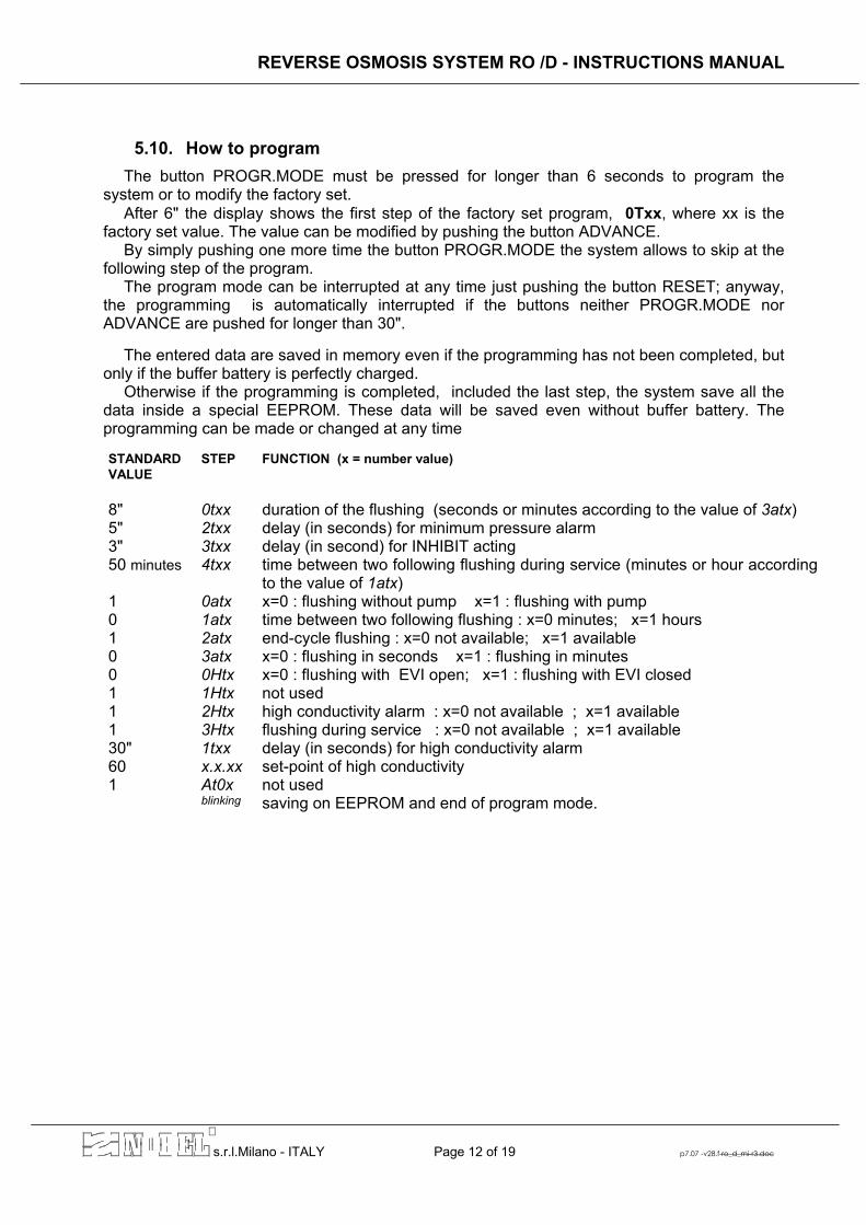
5.10. How to program The button PROGR.MODE must be pressed for longer than 6 seconds to program the
system or to modify the factory set. After 6" the display shows the first step of the factory set program, 0Txx, where xx is the
factory set value. The value can be modified by pushing the button ADVANCE. By simply pushing one more time the button PROGR.MODE the system allows to skip at the
following step of the program. The program mode can be interrupted at any time just pushing the button RESET; anyway,
the programming is automatically interrupted if the buttons neither PROGR.MODE nor ADVANCE are pushed for longer than 30".
The entered data are saved in memory even if the programming has not been completed, but
only if the buffer battery is perfectly charged. Otherwise if the programming is completed, included the last step, the system save all the
data inside a special EEPROM. These data will be saved even without buffer battery. The programming can be made or changed at any time
STANDARD VALUE
STEP FUNCTION (x = number value)
8" 0txx duration of the flushing (seconds or minutes according to the value of 3atx) 5" 2txx delay (in seconds) for minimum pressure alarm 3" 3txx delay (in second) for INHIBIT acting 50 minutes 4txx time between two following flushing during service (minutes or hour according
to the value of 1atx) 1 0atx x=0 : flushing without pump x=1 : flushing with pump 0 1atx time between two following flushing : x=0 minutes; x=1 hours 1 2atx end-cycle flushing : x=0 not available; x=1 available 0 3atx x=0 : flushing in seconds x=1 : flushing in minutes 0 0Htx x=0 : flushing with EVI open; x=1 : flushing with EVI closed 1 1Htx not used 1 2Htx high conductivity alarm : x=0 not available ; x=1 available 1 3Htx flushing during service : x=0 not available ; x=1 available 30" 1txx delay (in seconds) for high conductivity alarm 60 x.x.xx set-point of high conductivity 1 At0x not used blinking saving on EEPROM and end of program mode.

REVERSE OSMOSIS SYSTEM RO /D - INSTRUCTIONS MANUAL
s.r.l.Milano - ITALY Page 13 of 19 p7.07 -v28.f ro_d_mi-r3.doc
6. Service
6.1. How to insert or replace membranes (see DIAGRAM OF THE SYSTEM)
• be sure that the main power switch is turned on position "0" (control panel QE OFF) • take off all the caps of the membrane housings M, loosening the closing rings which keep
the caps fixed to the housings themselves. • after removed the caps, release the housings from the holding brackets which keep them
fixed to the skid. • (replacing) take out the membrane from the housings pushing them according to the
arrows marked on the housings. • rinse each and every new membrane with plenty running water to remove most of the
preservative solution of which the membrane is filled. • insert the membranes inside the housings according to the arrows marked on the
housings and the direction of water flow through the seal of the membrane ends (according to figure). Push firmly in order that the membrane is perfectly seated inside its housing.
• fix again the housing on the skid inserting them in the special brackets; check of the correct position of the housing, according to the arrow on the housing and as shown on DIAGRAM OF THE SYSTEM.
• place again the caps on the housing ends and fix them with their special closing rings removed before.
After the replacement of the membranes, follow the directions of "Starting-up & adjustment", to re-start again the working of the system (see § 6.2 page 14). CAUTION: the sealing gasket of membranes and housings can be lubricated, before
inserting, using glycerine, for perfect sealing and sliding. NEVER USE SILICONE GREASE !!

REVERSE OSMOSIS SYSTEM RO /D - INSTRUCTIONS MANUAL
s.r.l.Milano - ITALY Page 14 of 19 p7.07 -v28.f ro_d_mi-r3.doc
6.2. Starting-up & adjustment New membranes are usually filled with a preservative solution, as well as after a long non-
working period of the system. Therefore, at the starting-up of the system and when the system is re-started after a long
non-working period the membranes are filled with preservative solution. After a cleaning operation, instead, the membrane are still filled with detergent solution. Hence, in both cases, it is required to remove completely the preservative or detergent from
the membranes before that treated water can be used. The operations is made as follows: (see "DIAGRAM OF THE SYSTEM") • be sure that the power switch of power control panel QE is OFF. • divert temporarily the permeate (U) flow to the drain • open completely the needle regulation valve VS • close completely the needle regulation valve VR • open slowly the water inlet valve of the system. In order to easy the filling of the filters F,
release slightly the air-valve placed on the top side of the filters themselves. • switch ON the main power of QE control board; the system will start to work if the position
of level switches is accorded with water supplying; otherwise it is required to hand-driven the working of the system as above explained (hand-driven command on control panel QE).
• after several minutes of working the flow rates can be checked and adjusted (in case the system is working by hand-driven control, the min pressure switch is disabled; hence it is required to check carefully the pressure gauges M1 and M2 in order to realize if there is the required minimum inlet pressure of water)
• adjust the needle valve VS, mounted on the drain line of the membranes, in order that the flow rate of permeate (flow meter F1, installed only on models RO201, RO202, RO203) meet the technical data of the system. The value of pressure shown on pressure gauge M2, after the adjustment of VS valve, is the normal working pressure of the system according to the available raw water quality (chemical composition, temperature, etc.) An adjustable recirculating system is available in order to reduce the quantity of
concentrated (drain) water and/or reduce the working pressure. Proceed as follows : • adjust the needle valve VR to recirculate part of concentrated water in order to reduce the
flow rate of water carried to drain. The adjustment of the valve VR cause also the modification of the working pressure, hence a new adjustment of valve VS is required, until both values pressure/flow rate are the ones desired.
• After the adjustment have been completed, and after rinsed the membranes, connect the permeate line, which has been previously diverted to drain, to the storage tank of treated water.

REVERSE OSMOSIS SYSTEM RO /D - INSTRUCTIONS MANUAL
s.r.l.Milano - ITALY Page 15 of 19 p7.07 -v28.f ro_d_mi-r3.doc
NOTE: The best ratio treated water/drain water (permeate/concentrated) can be decided according to the characteristics of raw water. The higher is the value of the ratio, the higher is the risk of membrane fouling, furthermore if the hardness of raw water is high. However, even if the raw water is soft (naturally or processed by a softener), it is recommended that the above concentration ratio should not be higher than 1 (permeate/concentrated)
CAUTION : Normally, the longest life of the membrane depends on the lowest working pressure, with same other operating conditions. Therefore, should the quantity of treated water (permeate) is satisfactory, the system can work at a working pressure lower than the stated one.
CAUTION : The treated water (permeate) supplied during the first hour of working of the
system must not be used, since it can still contain residual of preservative chemical. When this solution will be completely flushed away, the treated water line (permeate) can be connected to the storage tank.
6.3. Special instructions of use • It is STRICTLY required that the contents of chlorine in raw water must be lower than 0.1
ppm; higher quantity can seriously damage the membrane. • Raw water temperature should be between 10° and 40° C (50° F < t < 104° F), and pH
value between 3 and 10.
• Whether a non-working period, longer than one week is expected, it is suggested to fill the membranes with a preservative solution containing 1% of sodium disulphite (NaHSO3) in water treated by RO system.
The preservative is injected into the membranes using an auxiliary tank and the same tubing connecting the filters outlet to the suction line of the pump. Close the inlet shut-off valve, disconnect temporarily the tubing from the filter and connect it to the auxiliary tank with chemical. The solution is simply drawn by the high-pressure pump P.
At the re-start of the system it is required to remove the preservative from the membranes, the same way described at § 6.2 page 14 "Starting-up & adjustment".

REVERSE OSMOSIS SYSTEM RO /D - INSTRUCTIONS MANUAL
s.r.l.Milano - ITALY Page 16 of 19 p7.07 -v28.f ro_d_mi-r3.doc
7. Maintenance
7.1. Periodical monitoring The system requires, as periodical maintenance, the cleaning or replacing of the cartridge of filters. Special instructions : • check monthly the values of pressure and flow rate of the water; they have to comply with
ones stated by the manufacturer. • clean the 50 µm pre-filter, whether installed, when its cartridge is clearly dirty. (max
allowable pressure drop of the filters is 0.8 bar - 80 kPa) • replace the 5 µm filtering cartridges model CRF 25/5 of the filters F and activated carbon
cartridge CRC10 of the filter AC, at least every six months, according to the quality of raw water or when the inlet pressure decreases (max allowable pressure drop of the filters is 0.8 bar - 80 kPa). Before the opening of the filter close the inlet shut off ball valve V1; follow the attached special directions of the filters.
• replace the RO membranes, when the quality and/or quantity of treated water (permeate) is not satisfactory any more. Whether the raw water is adequately pre-treated the life of membranes is usually longer than 3-4 years (even 5-6 years). Therefore, the life of membranes depends on the quality of water to be processed.
After the replacement of filters and/or membranes, to re-start the system follow the directions described at § 6.2 "Starting-up & adjustment".
7.2. How to adjust the min pressure switch PC The factory set point of the pressure switch PC is approx. 1 bar (100kPa). Whether further
adjustment should be required, proceed as follows : • switch OFF the main power of the control panel QE. • remove the cap of the electrical connector on the head of the pressure switch, by
unscrewing the screw placed in the center of the cap. • unscrew 2 turns the hexagonal head holed screw placed in the center of the pressure
switch. • using a (cut edge) screwdriver, through the hole of the hexagonal head screw, adjust the
turns of the internal screw of the pressure switch until the correct set-point is reached. • to check if the adjustment has been correctly made, put on again for a while the cap on
the electrical connector, switch the power ON, start the pump on "AUT" and close partially the inlet valve V1, in order that the min pressure switch acts. Check on the pressure gauge M1, on filter inlet line, the set value of pressure of the pressure switch.
• when the adjustment is completed, screw on again the holed screw in the center and the electrical connector.
REVERSE OSMOSIS SYSTEM RO /D - INSTRUCTIONS MANUAL
s.r.l.Milano - ITALY Page 17 of 19 p7.07 -v28.f ro_d_mi-r3.doc
7.3. Cleaning of the membranes
The operation of membrane cleaning must be performed only by skilled and authorized operators, using proper tools and CE marked personal protection devices (gloves, masks, cloths). The operator must be aware of the hazard and danger of the chemicals used in the process. It is also required to follow strictly the directions mentioned on the safety bulletins of the chemicals themselves.
During the normal working, but during the non-working as well, the membranes can be fouled
according to the quality of raw water and the operating conditions; hence a cleaning of the membranes can be required, using proper and suitable detergent (see "Table of chemicals for cleaning" in the next page)
In these cases, it is suggested to apply the Nobel service point closest to you or our technical dept.
The cleaning of the membranes is made by dipping them into a detergent solution. Proceed as follows :
• prepare the detergent solution in auxiliary tank, large enough to contain the membranes of the system. To dilute the chemical use treated water (permeate) supplied by the system.
• withdraw the membranes from their own housings (see § 6.1) and dip them into the solution which should be prepared before; keep caution that the temperature and pH of the solution must be within the values shown on the same table.
• withdraw the membrane and dip them several times in the cleaning solution in order to change the solution inside the membrane.
• after 20-30 minutes of cleaning, rinse the membrane with running water and, then, put the membrane inside their own housing again.
• whether required, repeat the operation of cleaning, possibly using a different chemical, after rinsing roughly the membrane with water.
Before to start the service, It is required to remove accurately the residual detergent inside the membranes, the same way described at § 6.2 "Starting-up & adjustment".
CAUTION : the dumping of the solution used to clean the membranes must be made
according to local laws concerning the waste and environmental protection. Follow the instructions mentioned on technical bulletin of the chemical used.
7.4. Disposal In the case of the disposal of the system or components of it, follow local laws and
regulations concerning the materials of which they are made. Take note that membranes and filtering elements are classified as simple plastic material, they are not toxic or harmful.

REVERSE OSMOSIS SYSTEM RO /D - INSTRUCTIONS MANUAL
s.r.l.Milano - ITALY Page 18 of 19 p7.07 -v28.f ro_d_mi-r3.doc
7.5. Table of chemicals for membranes cleaning
DETERGENTE / DETERGENT / CLEANER
TIPO DI SPORCO /
SALETE’ / FOULANT
0.1
% (w
) NaO
H
0.1
% (w
) Na-
EDTA
pH
12,
30
°C M
AX
0.1
% (w
) NaO
H
0.1
% (w
) Na-
DSS
pH
12,
30
°C M
AX
1.0
% (W
) STP
1.
0 %
(W) T
SP
1.0
% (W
) Na-
EDTA
0.5
% (V
) HC
l 0.
5 %
(W) H
3PO
4
2.0
% (W
) Aci
do c
itric
o /
Aci
de C
itriq
ue /
Citr
ic A
cid
0.2
% (W
) NH
2SO
3H
2.4
% (W
) Na 2
S 2O
4
2.4
% (W
) Aci
do c
itric
o /
Aci
de C
itriq
ue /
Citr
ic A
cid
2.4
% (W
) NH
4F-H
F pH
1.5
-2.5
, 30
°C M
AX
Sali Inorganici / Sels Inorganiques Inorganic Salts (per esempio / par exemple / for example: CaCO3 - CaSO4 - BaSO4)
BEST OK OK OK OK
Ossidi Metallici / Oxjdes Métalliques / Metal Oxides (per esempio / par exemple / for example: Ferro - Fer - Iron)
GOOD OK GOOD
Inorganici Colloidali / Colloïdaux Inorganiques / Inorganic Colloids (silt)
GOOD OK
Silice / Silice / Silica OK BEST
Biofilms BEST GOOD GOOD
Organici / Organiques / Organics OK GOOD GOOD
1. (W) Peso percentuale. (V) Volume percentuale. Cosí 2.0 % (W) acido citrico significa : 2 grammi di acido citrico sciolto in 98 grammi d’acqua. 2. Simboli chimici delle sostanze incrostanti, nell’ordine: CaCO3 = carbonato di calcio. CaSO 4= solfato di calcio. BaSO4 = solfato di bario. 3. Simboli chimici dei detergenti nell’ordine: NaOH = idrossido di sodio. Na-EDTA = sodio etilen-diammino-tetra-acetato Na-DDS = sodio dodecilsulfato. STP = sodio trifosfato (Na5P3O10). TSP = fosfato trisodico (Na3PO4 - 12H2O). HCl = acido cloridrico. H3PO4 = acido fosforico. NH2SO3H = acido sulfammico. Na2S2O4 = sodio idrosolfito. NH4F- HF = ammonio bifluoruro.
1. (W) pourcentage poids . (V) pourcentage volume. Aussi 2.0 % (W) signifie : 2 grammes d’acide citrique dissout en 98 grammes d’eau. 2. Symboles chimiques des substances incrustantes, en ordre : CaCO3 = carbonate de calcium. CaSO 4 = sulfate de calcium. BaSO4 = sulfate de baryum. 3. Symboles chimiques des détergents utilisés, en ordre: NaOH = hydroxyde de sodium. Na-EDTA sel sodium de acide tetracétique de diéthylamine . Na-DDS = sels de sodium dodecylsulfate. STP = sodium triphosphate (Na5P3O10). TSP = trisodium phosphate (Na3PO4 - 12H2O). HCl = acide hydrochlorique. H3PO4 = acide phosphorique. NH2SO3H = acide sulfamique. Na2S2O4 = sodium hydrosolfite. NH4F- HF = ammonium bifluorure.
1. (W) denotes weight percent. (V) denotes volume percent. So 2.0 % (W) citric acid means 2 grams of citric acid dissolved in 98 grams of water. 2. Foulant chemical symbols in order used : CaCO3 = calcium carbonate. CaSO 4 = calcium sulfate. BaSO4 = barium sulfate. 3. Cleaning chemical symbols, in order used: NaOH = sodium hydroxyde. Na-EDTA sodium salt of ethylene diamine tetraacetic acid. Na-DDS = sodium salt of dodecylsulfate. STP = sodium triphosphate (Na5P3O10). TSP = trisodium phosphate (Na3PO4 - 12H2O). HCl = hydrochloric acid. H3PO4 = phosphoric acid. NH2SO3H = sulfamic acid. Na2S2O4 = sodium hydrosulfite. NH4F- HF = ammonium bifluoride

REV
ERSE
OSM
OSI
S SY
STEM
SER
IE R
O /D
- IN
STR
UC
TON
S M
AN
UA
L
s.r.
l.Mila
no -
ITA
LY
Pag
e 19
of 1
9 p7
.07
d50
8416
-v28
.f ro
_d_m
i-r3.
doc
8.
Trou
ble
shoo
ting
guid
e
PRO
BLE
M
CA
USE
H
OW
TO
SO
LVE
Hig
h co
nduc
tivity
of t
reat
ed w
ater
(p
erm
eate
) To
o lo
w p
ress
ure
on m
embr
anes
. Le
akag
e of
unt
reat
ed w
ater
thro
ugh
O-r
ing
seal
s of
mem
bran
es.
The
pres
erva
tive
or d
eter
gent
sol
utio
n ha
s no
t bee
n re
mov
ed c
ompl
etel
y.
Spo
iled
mem
bran
es
Incr
ease
the
pres
sure
by
adju
stin
g th
e va
lve(
s) V
S, V
R.
With
draw
the
mem
bran
es a
nd c
heck
the
inte
grity
and
the
corr
ect
plac
ing
of O
-rin
gs. R
epla
ce o
r pla
ce c
orre
ctly
them
. R
inse
mem
bran
es w
ith h
igh
flow
rate
of w
ater
. R
epla
ce th
e m
embr
anes
. Lo
w p
ress
ure
treat
ed w
ater
(p
erm
eate
). To
o lo
w p
ress
ure
on m
embr
anes
. Fo
uled
mem
bran
es.
Spo
iled
mem
bran
es
Incr
ease
the
pres
sure
by
adju
stin
g th
e va
lve(
s) V
S, V
R.
Was
h th
e m
embr
anes
. R
epla
ce th
e m
embr
anes
. Th
e pr
essu
re d
oes
not i
ncre
ase
V
alve
VS
and
/or V
R a
re n
ot p
rope
rly
adju
sted
. Fl
ushi
ng s
olen
oid
valv
e is
dirt
y or
spo
iled
and
does
not
clo
se p
erfe
ctly
. Th
ere
is a
ir in
side
the
pum
p.
The
pum
p is
spo
iled.
Adj
ust c
orre
ctly
val
ve V
S a
nd/o
r VR
. C
lean
or r
epla
ce th
e so
leno
id v
alve
. P
urge
air
off t
he p
ump.
R
epai
r and
/or r
epla
ce th
e pu
mp.
M
inim
um p
ress
ure
alar
m a
cts
beca
use
the
inle
t pre
ssur
e up
stre
am o
f the
pum
p is
< 1
bar
(1
00 k
Pa)
*
Shu
t off
valv
es o
f the
filte
rs a
re c
lose
d.
The
pre-
filte
rs a
re c
logg
ed
Inle
t wat
er p
ress
ure
is to
o lo
w
Inle
t sol
enoi
d va
lve
is d
efec
ted.
Ope
n sh
ut-o
ff va
lves
of t
he fi
lters
. C
lean
or r
epla
ce th
e fil
terin
g el
emen
ts.
Che
ck th
e av
aila
ble
wat
er.
Rep
lace
the
sole
noid
val
ve.
Min
imum
pre
ssur
e al
arm
act
s al
thou
gh t
he in
let p
ress
ure
upst
ream
of t
he p
ump
is >
1 b
ar
(100
kP
a) *
Pre
ssur
e sw
itch
is d
efec
ted.
Th
e pr
essu
re s
witc
h is
not
pro
perly
adj
uste
d.R
epla
ce th
e pr
essu
re s
witc
h.
Adj
ust t
he p
ress
ure
switc
h.
Ther
e is
a p
assa
ge o
f wat
er d
urin
g no
n-w
orki
ng o
f the
sys
tem
. Th
e in
let s
olen
oid
valv
e is
dirt
y or
spo
iled
and
does
not
clo
se p
rope
rly.
Cle
an o
r rep
lace
the
sole
noid
val
ve.
*
CA
UTI
ON
: pr
essu
re u
pstre
am o
f the
pum
p m
ust b
e ch
eckl
ed w
hen
the
pum
p is
wor
king
, sin
ce th
is is
the
oper
atin
g co
nditi
on w
hen
the
pres
sure
sw
itch
alar
m a
cts.

ALLESTIMENTI IMPIANTI OSMOSI INVERSAREVERSE OSMOSIS UNITS FITTING OUT
•o-*
di seriedisponibile su richiestanon disponibiledisponibile come unità esterna (vedi pre-trattamenti)
RO
214
DR
O 2
21D
RO
201
DR
O 2
02D
RO
203
DR
O 4
02M
RO
403
MR
O 4
04M
RO
404
ER
O 4
06E
RO
409
ER
O 4
12E
RO
804
ER
O 8
06E
RO
809
ER
O 8
12E
RO
815
E
•o-*
standardavailable upon requestnot availableavailable as external unit (see pre-treatment)
POMPA PRESSURIZZAZIONE BOOSTER PUMP
acciaio inox AISI 304 • • • • • • • • • • • • • • − − − stainless steel AISI 304
acciaio inox AISI 316 - - - - - ο ο ο ο ο ο ο ο ο • • • stainless steel AISI 316
VESSEL VESSEL
acciaio inox AISI 304 • • • • • - - - - - - - - - - - - stainless steel AISI 304
acciaio inox AISI 316 - - - - - • • • • • • • • • • • • stainless steel AISI 304
vetroresina ο ο ο ο ο ο ο ο ο ο ο ο ο ο ο ο ο fiberglass
ELETTROVALVOLA INGRESSO INLET SOLENOID VALVE
ottone • • • • • • • • • • • • • • • • • brass
PVC - - - - - ο ο ο ο ο ο ο ο ο ο ο ο PVC
PRESSOSTATO MINIMA MINIMUM PRESSURE SWITCH
ottone • • • • • • • • • • • • • • − − − brass
acciaio inox AISI 316 ο ο ο ο ο ο ο ο ο ο ο ο ο ο • • • stainless steel AISI 316
VALVOLA REGOLAZIONE PRESS. POMPA PUMP PRESS. REGULATION VALVE
acciaio inox AISI 316 - - - - - - - - • • • • • • • • • stainless steel AISI 316
VALVOLA REGOLAZIONE PORTATA SCARICO DRAIN FLOW REGULATION VALVE
acciaio inox AISI 316 ο ο ο ο o • • • • • • • • • • • • stainless steel AISI 316
ottone • • • • • - - - - - - - - - - - - brass
TUBAZIONI BASSA PRESSIONE LOW PRESSURE TUBING
PVC - - - - - • • • • • • • • • • • • PVC
nylon • • • • • - - - - - - - - - - - - nylon
TUBAZIONI ALTA PRESSIONE HIGH PRESSURE TUBING
nylon • • • • • - - - - - - - - - - - - nylon
acciaio inox AISI 316 - - - - - • • • • • • • • • • • • stainless steel AISI 316
MEMBRANE ACQUA SALMASTRA • • • • • • • • • • • • • • • • • BRACKISH WATER MEMBRANESVALVOLA FLUSSAGGIO AUTOMATICO AUTOMATIC FLUSH VALVE
ottone - - • • • • • • • • • • • • • • • brass
acciaio inox AISI 316 - - - - - ο ο ο ο ο ο ο ο ο ο ο ο stainless steel AISI 316
QUADRO DI COMANDO CONTROL BOARD
monofase • • • • • - - - - - - - - - - - - single-phase
trifase combi - - - - - • • • - - - - - - - - - three-phases combi
trifase - - - - - - - - • • • • • • • • • three-phases
pre-filtro 5µm • • • • • • • • • • • • • • • • • 5µm pre-filterpre-filtro a carbone attivo • • • • • * * * * * * * * * * * * activated carbon pre-filtermanometro ingresso filtri • • • • • • • • • • • • • • • • • filters inlet pressure gaugemanometro ingresso pompa - - - - - • • • • • • • • • • • • pump inlet pressure gaugemanometro ingresso membrane • • • • • - - - • • • • • • • • • membranes inlet pressure gaugemanometro intermedio membrane - - - - - - - - • • • • • • • • • intermediate stage pressure gaugemanometro concentrato - - - - - • • • • • • • • • • • • drain flow pressure gaugeprogrammatore elettronico • • • • • • • • • • • • • • • • • electronic programmercella conducibilità AISI 316/PVC • • • • • • • • • • • • • • • • • conductivity probe AISI 316/PVCconduttimetro digitale • • • • • • • • • • • • • • • • • digital conductivity meterflussimetro concentrato - - • • • • • • • • • • • • • • • drain line flow meterflussimetro permeato - - • • • • • • • • • • • • • • • product water line flow metersistema ricircolo regolabile • • • • • • • • • • • • • • • • • adjustable recirculating systemskid in acciaio inox AISI304 • • • • • • • • • • • • • • • • • stainless steel AISI 304 skidpredisposizione lavaggi − − − − − • • • • • • • • • • • • washing arrangementsrev. 2
RO_MANUAL.XLS 05/11/02