Embed Size (px)
DESCRIPTION
The purpose of this project was to learn the Reverse Engineering techniques & to utilize all the techniques used in material’s investigation. RE was performed on a finished metal part, and different techniques were performed on this part to identify the grade of the metal used in that part. Different studies of material’s properties were also conducted along the identification.
Citation preview

SEPTEMBER 2009
Submitted to:
DR. ASHRAF ALI MEO
Chairman, Materials Engineering Department, NED University of Engineering & Technology, Karachi
REVERSE ENGINEERING PROJECT
REPORT
The purpose of this project was to learn the Reverse Engineering techniques & to utilize all the techniques used in material’s investigation. RE was performed on a finished metal part, and different techniques were performed on this part to identify the grade of the metal used in that part. Different studies of material’s properties were also conducted along the identification.
By MUHAMMAD KAMRAN BHATTI
(Student of TE - Materials Engineering)
P a g e | 1
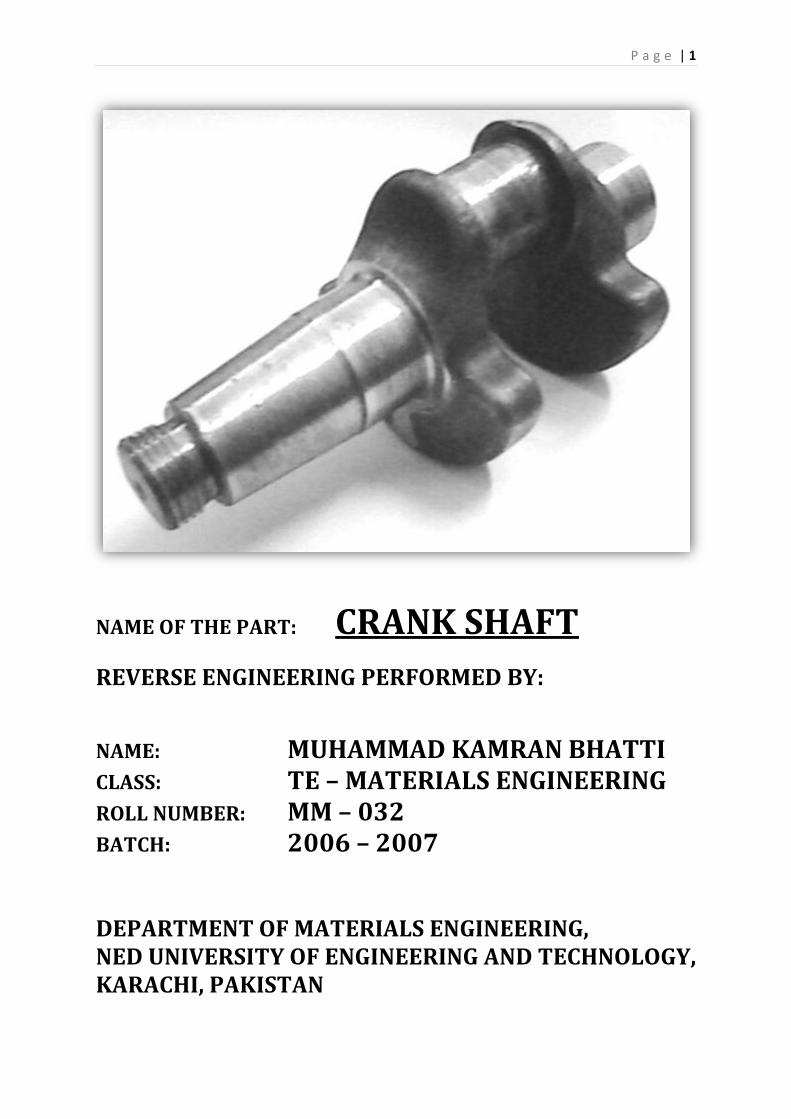
NAME OF THE PART: CRANK SHAFT
REVERSE ENGINEERING PERFORMED BY:
NAME: MUHAMMAD KAMRAN BHATTI
CLASS: TE – MATERIALS ENGINEERING ROLL NUMBER: MM – 032
BATCH: 2006 – 2007 DEPARTMENT OF MATERIALS ENGINEERING, NED UNIVERSITY OF ENGINEERING AND TECHNOLOGY, KARACHI, PAKISTAN

P a g e | 2
CONTENTS
PAGE #
OBJECTIVES (as directed by the Chairman MMD) 4 PREFACE 5 ACKNOWLEDGMENT 6 INTRODUCTION 7
CHAPTER ONE
1 - THEOROTICAL ASPECT 9 - 21 1.1 – CRANKSHAFT 9
1.1.1 – HISTORY 9 1.1.2 – BEARINGS 9 1.1.3 - PISTON STROKE 10 1.1.4 – CONSTRUCTION 10
1.2 - AISI 1045 - PLAIN CARBON STEEL 12 1.3 - HEAT TREATMENT TECNIQUES ON AISI 1045 14
1.3.1 – ANNEALING 14 1.3.2 – NORMALIZING 15 1.3.3 – HARDENING 15 1.3.4 – TEMPERING 16
1.4 – METALLOGRAPHY 17 1.5 – ROCKWELL HARDNESS TESTER 18 1.6 - X-RAY FLUORESCENCE (XRF) 20
CHAPTER TWO
2 - PRACTICAL WORK 21 - 50 2.1 – PHOTOGRAPHS IN AS RECEIVED CONDITION 22 2.2 – SECTIONING 25 2.3 - HARDNESS PROFILE IN AS RECEIVED CONDITION 27 2.4 – MICROSTRUCTURE IN AS RECEIEVED CONDITION 28
2.4.1 - IN LATERAL DIRECTION OF CRANKSHAFT 28 2.4.2 - IN LONGITUDENAL DIRECTION OF CRANKSHAFT 30

P a g e | 3
2.5 - XRF ANALYSIS 34 2.6 – LIGHT EMISSION SPECTROSCOPY 35 2.7 – IDENTIFICATION 35
2.7.1 – GRADE 35 2.7.2 – MANUFACTURING PROCESS 36
2.8 – HEAT TREATMENTS PERFORMED 37 2.8.1 – ANNEALING 38 2.8.1.1 – Annealed hardness 38 2.8.1.2 – Annealed microstructures 38 2.8.2 – NORMALIZING 41 2.8.2.1 – Normalized hardness: 41 2.8.2.2 – Normalized microstructures 41 2.8.3 –HARDENING 44 2.8.3.1 – Quenched hardness 44 2.8.3.2 – Quenched microstructures 44 2.8.4 – TEMPERING 47 2.8.4.1 – Tempered hardness 47 2.8.4.2 – Tempered microstructures 47
2.9 – HARDNESS PROFILES AFTER HEAT TREATMENTS 50 2.9.1 - ANNEALED TO NORMALLIZED - HRB PROFILE 50 2.9.2 – QUENCHED TO TEMPERED – HRC PROFILE 50
SUMMARY 51 GOALS 52

P a g e | 4
OBJECTIVES (AS DIRECTED BY THE CHAIRMAN MMD Dr. ASHRAF ALI MEO)
REVERSE ENGINEERING/TECHNIQUES
PROJECT’S PLAN
Objectives: To provide a learning opportunity by reverse
engineering utilising all the techniques used in material’s
investigation.
1. Get a metallic “PART” of minimum size =25mm x 25mm or 25mm in diameter [Wrought samples such rods, sheets, squares etc., will not serve the purpose!]
2. Get photograph of the component-take at least five pictures in different directions!
3. Make sketches (in all directions) and mark the position for hardness test, metallography and microscopy in as-received condition
4. Get hardness profile across the sample. 5. Get sample for metallography, microscopy and XRF analysis from all
areas of different hardness regions. 6. Prepare the samples for metallohgraphy and study the microstructure
get at least 6 to 10 micrograph from different region of the samples. 7. Go to the library, compare the microstructure of your sample from
Metals Handbook and other books on microstructures and identify it. 8. Get XRF analysis from all the areas of different hardness. 9. Identify the sample material/s from chemical composition 10. Go to the library do literature survey and see “what type of heat
treatment is possible” on the sample. A TTT diagram will be helpful. 11. Workout heat treatment cycles. 12. Discuss all your results and data with the project Advisor. 13. Perform heat treatment 14. GO To number 4 15. Make a report of all the work.
P a g e | 5
PREFACE
The purpose of this report is to explain what we did and
learned during Reverse Engineering Project.
The report focuses primarily on the Metallurgical aspects
of the Reverse Engineering. The various parts of the report
reflect the analytical and theoretical part of reverse
engineering, its successes, observations and key processes.
The report also gives an efficient overview of all the
technical and statistical norms of an unknown sample
after being reverse engineered.
It is hoped that this report would serve as a cardinal
vehicle to the new students of Materials Engineering.

P a g e | 6
ACKNOWLEGEMENTS I am, grateful to be engaged with such a well coordinated and behaved
faculty of Materials Engineering Department.
I have developed a deep respect for Materials Engineering Management &
faculty members, especially the entrepreneurial spirit and the passion of
Chairman Materials Engineering Prof. Dr. ASHRAF ALI MEO for
excellence he bring to this Department.
I am very much thankful to all of the concerned people, due to whom my
project became possible,
I like to mention their names with full devotion and respect,
Prof. Dr. Ashraf Ali Meo. (Chairmain, Department of Materials Engineering, NEDUET)
Engr. Mr. Fayaz Hussain. ( Lecturer and Project Advisor )
Engr. Mr. Ghufran (PSM) (Lecturer )
Moreover, i also like to thanks the persons in the laboratories who
helped me alot in all the project work.
Mr. Zahid. (Metallography lab)
Mr. Kamran (Heat treatment Lab)
Equally valuable has been their contribution. Because of the help of all, my
experience with this project gives me great confidence.

P a g e | 7
INTRODUCTION
This report consists of two chapters.
1. Theorotical Aspect
2. Practical work
The first chapter of the report comprises to all the theoretical knowledge about
the techniques, processes, and equipments used in this Reverse engineering
project. This chapter mainly includes:
Introduction to Crankshaft
Some properties of AISI 1045 Plain Carbon Steel
Literature about the Heat treatment techniques, which applied on
Crankshaft specimens
Some knowledge about the Metallography, Rockwell hardness Tester,
XRF technique which were the basis of all the project
The second chapter which is the back bone of this report, includes all the
practical performance done during all this project. It starts from selection of a
finished part (Crankshaft) to the identification of the steel grade used in that
crankshaft and further goes towards the material’s properties investigation
techniques that is heat treatments, Metallography, hardnessmeasurements etc.
the second chaptermainly includes:
Photographs in as received condition,
Different heat treatments techniques performed on different sections of
crankshaft,
Hardness measurements in as received and heat treated form,
Metallography done in as received and heat treated form in different
magnifications,
Metal composition analysis i.e. Spectroscopy (XRF) done in MMD XRF
lab and from PSM,
Steel grade identification with the help of hardness, microstructures, and
composition.
Moreover the report contains a comprehensive knowledge about all the steps
and procedures during the entire project. I hope the reader would be quite
pleasant to see and read this report.

P a g e | 8
BASED ON ALL THE THEORY RELATED TO STEP-WISE
EXPERIMENTAL WORK/TECHNIQUES PERFORMED ON THE
CRANKSHAFT INCLUDING:
Introduction to Crankshaft
Some properties of AISI 1045 Plain Carbon Steel
Literature about the Heat treatment techniques, which applied
on Crankshaft specimens
Some knowledge about the Metallography, Rockwell hardness
Tester, XRF technique which were the basis of all the project.
P a g e | 9
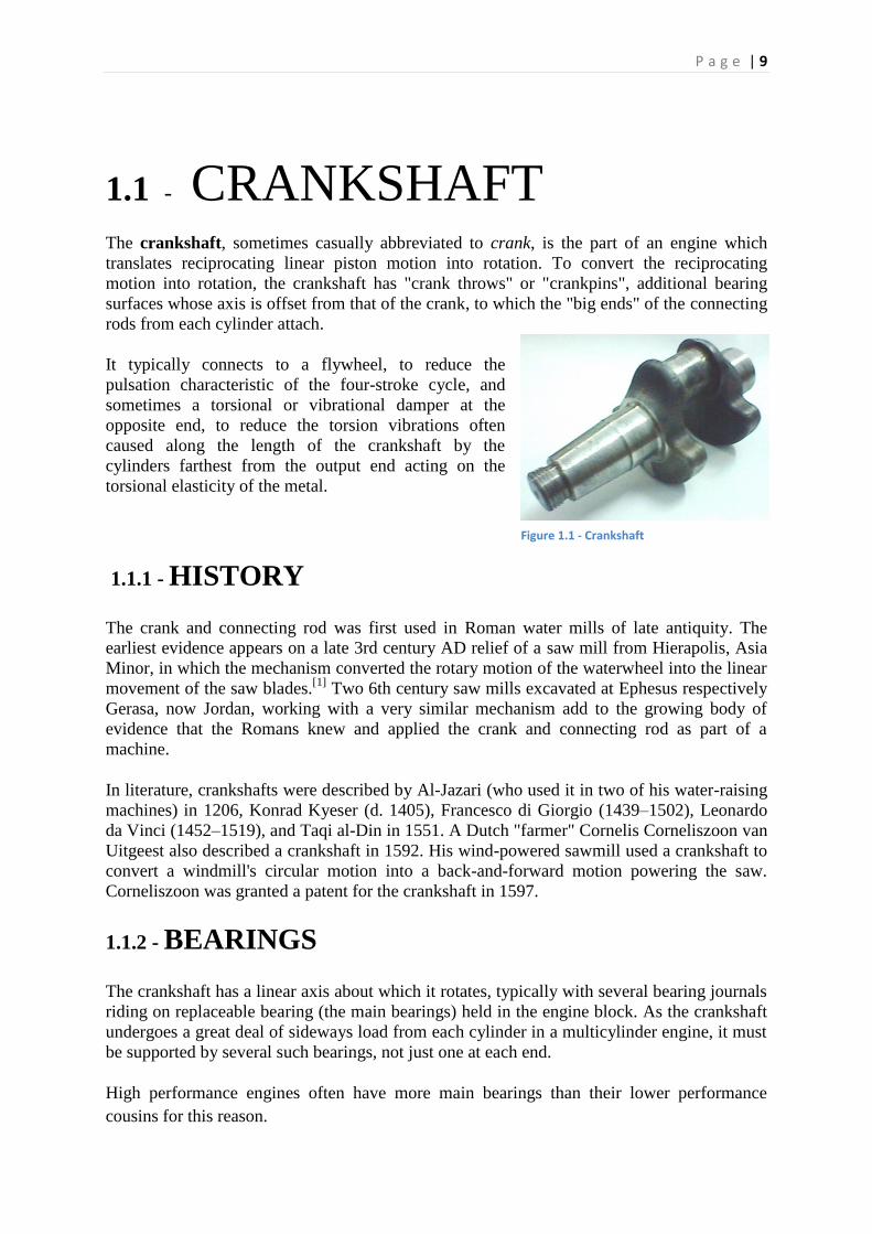
1.1 - CRANKSHAFT
The crankshaft, sometimes casually abbreviated to crank, is the part of an engine which
translates reciprocating linear piston motion into rotation. To convert the reciprocating
motion into rotation, the crankshaft has "crank throws" or "crankpins", additional bearing
surfaces whose axis is offset from that of the crank, to which the "big ends" of the connecting
rods from each cylinder attach.
It typically connects to a flywheel, to reduce the
pulsation characteristic of the four-stroke cycle, and
sometimes a torsional or vibrational damper at the
opposite end, to reduce the torsion vibrations often
caused along the length of the crankshaft by the
cylinders farthest from the output end acting on the
torsional elasticity of the metal.
1.1.1 - HISTORY
The crank and connecting rod was first used in Roman water mills of late antiquity. The
earliest evidence appears on a late 3rd century AD relief of a saw mill from Hierapolis, Asia
Minor, in which the mechanism converted the rotary motion of the waterwheel into the linear
movement of the saw blades.[1]
Two 6th century saw mills excavated at Ephesus respectively
Gerasa, now Jordan, working with a very similar mechanism add to the growing body of
evidence that the Romans knew and applied the crank and connecting rod as part of a
machine.
In literature, crankshafts were described by Al-Jazari (who used it in two of his water-raising
machines) in 1206, Konrad Kyeser (d. 1405), Francesco di Giorgio (1439–1502), Leonardo
da Vinci (1452–1519), and Taqi al-Din in 1551. A Dutch "farmer" Cornelis Corneliszoon van
Uitgeest also described a crankshaft in 1592. His wind-powered sawmill used a crankshaft to
convert a windmill's circular motion into a back-and-forward motion powering the saw.
Corneliszoon was granted a patent for the crankshaft in 1597.
1.1.2 - BEARINGS
The crankshaft has a linear axis about which it rotates, typically with several bearing journals
riding on replaceable bearing (the main bearings) held in the engine block. As the crankshaft
undergoes a great deal of sideways load from each cylinder in a multicylinder engine, it must
be supported by several such bearings, not just one at each end.
High performance engines often have more main bearings than their lower performance
cousins for this reason.
Figure 1.1 - Crankshaft
P a g e | 10
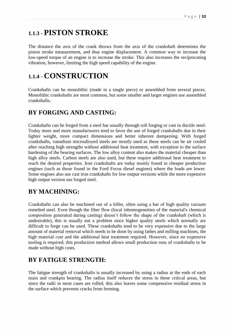
1.1.3 - PISTON STROKE
The distance the axis of the crank throws from the axis of the crankshaft determines the
piston stroke measurement, and thus engine displacement. A common way to increase the
low-speed torque of an engine is to increase the stroke. This also increases the reciprocating
vibration, however, limiting the high speed capability of the engine.
1.1.4 - CONSTRUCTION
Crankshafts can be monolithic (made in a single piece) or assembled from several pieces.
Monolithic crankshafts are most common, but some smaller and larger engines use assembled
crankshafts.
BY FORGING AND CASTING:
Crankshafts can be forged from a steel bar usually through roll forging or cast in ductile steel.
Today more and more manufacturers tend to favor the use of forged crankshafts due to their
lighter weight, more compact dimensions and better inherent dampening. With forged
crankshafts, vanadium microalloyed steels are mostly used as these steels can be air cooled
after reaching high strengths without additional heat treatment, with exception to the surface
hardening of the bearing surfaces. The low alloy content also makes the material cheaper than
high alloy steels. Carbon steels are also used, but these require additional heat treatment to
reach the desired properties. Iron crankshafts are today mostly found in cheaper production
engines (such as those found in the Ford Focus diesel engines) where the loads are lower.
Some engines also use cast iron crankshafts for low output versions while the more expensive
high output version use forged steel.
BY MACHINING:
Crankshafts can also be machined out of a billet, often using a bar of high quality vacuum
remelted steel. Even though the fiber flow (local inhomogeneities of the material's chemical
composition generated during casting) doesn’t follow the shape of the crankshaft (which is
undesirable), this is usually not a problem since higher quality steels which normally are
difficult to forge can be used. These crankshafts tend to be very expensive due to the large
amount of material removal which needs to be done by using lathes and milling machines, the
high material cost and the additional heat treatment required. However, since no expensive
tooling is required, this production method allows small production runs of crankshafts to be
made without high costs.
BY FATIGUE STRENGTH:
The fatigue strength of crankshafts is usually increased by using a radius at the ends of each
main and crankpin bearing. The radius itself reduces the stress in these critical areas, but
since the radii in most cases are rolled, this also leaves some compressive residual stress in
the surface which prevents cracks from forming.
P a g e | 11
BY HARDENING:
Most production crankshafts use induction hardened bearing surfaces since that method gives
good results with low costs. It also allows the crankshaft to be reground without having to
redo the hardening. But high performance crankshafts, billet crankshafts in particular, tend to
use nitridization instead. Nitridization is slower and thereby more costly, and in addition it
puts certain demands on the alloying metals in the steel, in order to be able to create stable
nitrides. The advantage with nitridization is that it can be done at low temperatures, it
produces a very hard surface and the process will leave some compressive residual stress in
the surface which is good for the fatigue properties of the crankshaft. The low temperature
during treatment is advantageous in that it doesn’t have any negative effects on the steel, such
as annealing. With crankshafts that operate on roller bearings, the use of carburization tends
to be favored due to the high Hertzian contact stresses in such an application. Like nitriding,
carburization also leaves some compressive residual stresses in the surface.
BY COUNTERWEIGHTS:
Some expensive, high performance crankshafts also use heavy-metal counterweights to make
the crankshaft more compact. The heavy-metal used is most often a tungsten alloy but
depleted uranium has also been used. A cheaper option is to use lead, but compared with
tungsten its density is much lower.
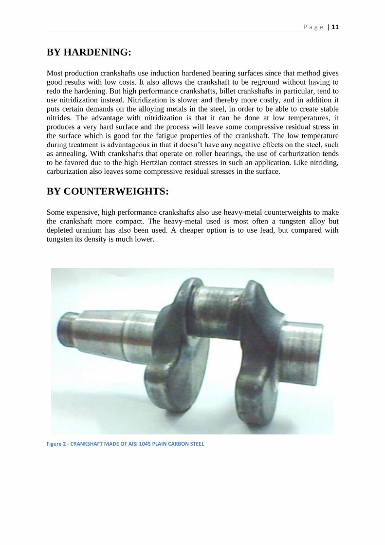
Figure 2 - CRANKSHAFT MADE OF AISI 1045 PLAIN CARBON STEEL
P a g e | 12
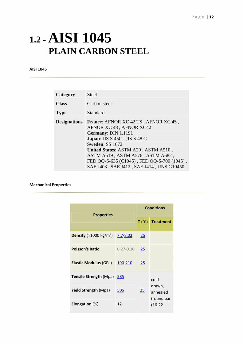
1.2 - AISI 1045 PLAIN CARBON STEEL
AISI 1045
Category Steel
Class Carbon steel
Type Standard
Designations France: AFNOR XC 42 TS , AFNOR XC 45 ,
AFNOR XC 48 , AFNOR XC42
Germany: DIN 1.1191
Japan: JIS S 45C , JIS S 48 C
Sweden: SS 1672
United States: ASTM A29 , ASTM A510 ,
ASTM A519 , ASTM A576 , ASTM A682 ,
FED QQ-S-635 (C1045) , FED QQ-S-700 (1045) ,
SAE J403 , SAE J412 , SAE J414 , UNS G10450
Mechanical Properties
Properties
Conditions
T (°C) Treatment
Density (×1000 kg/m3) 7.7-8.03 25
Poisson's Ratio 0.27-0.30 25
Elastic Modulus (GPa) 190-210 25
Tensile Strength (Mpa) 585
25
cold
drawn,
annealed
(round bar
(16-22
Yield Strength (Mpa) 505
Elongation (%) 12
P a g e | 13
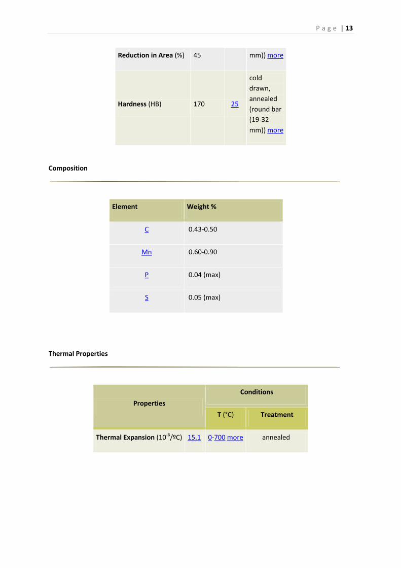
Reduction in Area (%) 45 mm)) more
Hardness (HB) 170 25
cold
drawn,
annealed
(round bar
(19-32
mm)) more
Composition
Element Weight %
C 0.43-0.50
Mn 0.60-0.90
P 0.04 (max)
S 0.05 (max)
Thermal Properties
Properties
Conditions
T (°C) Treatment
Thermal Expansion (10-6/ºC) 15.1 0-700 more annealed

P a g e | 14
1.3 - HEAT TREATMENT TECNIQUES
ON AISI 1045
AISI 1045 is a common grade in used in various applications like
shafts, crankshafts, forged parts, castings. Numerous heat treatment
techniques are employed over this grade to achieve the desired
properties required for the service conditions.
Following heat treatments, I performed on AISI 1045 carbon steel
crankshaft Sections.
1.3.1 - ANNEALING ANNEALING is a generic term denoting a treatment that consists of heating to and holding at a
suitable temperature followed by cooling at an appropriate rate, primarily for the softening of metallic
materials. Generally, in plain carbon steels, annealing produces a ferrite-pearlite microstructure. Steels
may be annealed to facilitate cold working or machining, to improve mechanical or electrical
properties, or to promote dimensional stability. The choice of an annealing treatment that will provide
an adequate combination of such properties at minimum expense often involves a compromise. Terms
used to denote specific types of annealing applied to steels are descriptive of the method used, the
equipment used, or the condition of the material after treatment.
The iron-carbon binary phase diagram can be used to better understand annealing processes. Although
no annealing process ever achieves true equilibrium conditions, it can closely parallel these
conditions. In defining the various types of annealing, the transformation temperatures or critical
temperatures are usually used.
SUPERCRITICAL OR FULL ANNEALING
A common annealing practice is to heat hypoeutectoid steels above the upper critical temperature (A3)
to attain full austenitization. The process is called full annealing. In hypoeutectoid steels (under 0.77%
C), supercritical annealing (that is, above the A3 temperature) takes place in the austenite region (the
steel is fully austenitic at the annealing temperature).
However, in hypereutectoid steels (above 0.77% C), the annealing takes place above the A1
temperature, which is the dual-phase austenite-cementite region. Figure 4 shows the annealing
temperature range for full annealing superimposed in the iron-carbon binary phase diagram. In
general, an annealing temperature 50 °C (90 °F) above the A3 for hypoeutectic steels and A1 for
hypereutectoid steels is adequate.
FULL ANNEALING TEMPERATURE OF AISI 1045
TEMPERATURE: 800 – 850 c
From a practical sense, most annealing practices have been established from experience. For many
annealing applications, it is sufficient simply to specify that the steel be cooled in the furnace from a
designated annealing (austenitizing) temperature.
Figure 3 - Annealing Furnace
P a g e | 15
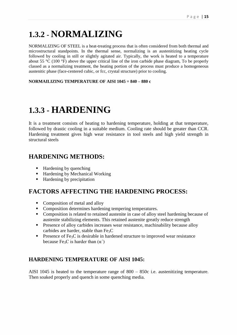
1.3.2 - NORMALIZING
NORMALIZING OF STEEL is a heat-treating process that is often considered from both thermal and
microstructural standpoints. In the thermal sense, normalizing is an austenitizing heating cycle
followed by cooling in still or slightly agitated air. Typically, the work is heated to a temperature
about 55 °C (100 °F) above the upper critical line of the iron carbide phase diagram, To be properly
classed as a normalizing treatment, the heating portion of the process must produce a homogeneous
austenitic phase (face-centered cubic, or fcc, crystal structure) prior to cooling.
NORMAILIZING TEMPERATURE OF AISI 1045 = 840 – 880 c
1.3.3 - HARDENING
It is a treatment consists of heating to hardening temperature, holding at that temperature,
followed by drastic cooling in a suitable medium. Cooling rate should be greater than CCR.
Hardening treatment gives high wear resistance in tool steels and high yield strength in
structural steels
HARDENING METHODS:
Hardening by quenching
Hardening by Mechanical Working
Hardening by precipitation
FACTORS AFFECTING THE HARDENING PROCESS:
Composition of metal and alloy
Composition determines hardening tempering temperatures.
Composition is related to retained austenite in case of alloy steel hardening because of
austenite stabilizing elements. This retained austenite greatly reduce strength
Presence of alloy carbides increases wear resistance, machinability because alloy
carbides are harder, stable than Fe3C
Presence of Fe3C is desirable in hardened structure to improved wear resistance
because Fe3C is harder than (α´)
HARDENING TEMPERATURE OF AISI 1045:
AISI 1045 is heated to the temperature range of 800 – 850c i.e. austenitizing temperature.
Then soaked properly and quench in some quenching media.
P a g e | 16
1.3.4 - TEMPERING
It is simply a reheating process for as hardened parts to optimize the mechanical properties
It is integral step in conventional hardening by quenching
Through Tempering transformational stresses can be eliminated
VARIABLES:
Variables associated with tempering, that affect microstructure & mechanical properties of
tempered steel include
Tempering temperature
Time at temperature
Cooling rate from the tempering temperature
Composition of steel, including carbon, alloy and residual elements
MICROSTRUCTURAL CHANGES DURING TEMPERING:
Based on x-ray, dilatometric, & microstructural studies a number of basic phenomenon
occurs during decomposition of martensite or tempering.
Redistribution of carbon atoms in bct lattices of Martensite
Precipitation of transition carbide (Є- carbide) bearing composition as (Fe2.4C also
called high carbon cementite) and cph structure
Partial loss of tetragonality of bct lattices of martensite
Decomposition of retained austenite into (α and Fe3C). This structure has often
called secondary bainite.
Conversion of Є- carbide into small rod shaped cementite particles
Spheriodization of rod shaped cementite
Recovery of ferrite structure
Recrystallization of ferrite structure
TEMPERING TEMPERATURE FOR AISI 1045:
AISI 1045 is usually tempered at 550c to 650c. Tempered Martensite is obtained after
tempering of a hardened (quenched) steel.
P a g e | 17
1.4 – METALLOGRAPHY
Metallography is the study of the physical structure and components of metals, typically using microscopy.
PREPARING METALLOGRAPHIC SPECIMENS
The surface of a metallographic specimen is prepared by various methods of grinding,
polishing, and etching. After preparation, it is often analyzed using optical or electron
microscopy. Using only metallographic techniques, a skilled technician can identify alloys
and predict material properties.
A systematic preparation method is easiest way to
achieve the true structure. Sample preparation must
therefore pursue rules which are suitable for most
materials. Different materials with similar properties
(hardness and ductility) will respond alike and thus
require the same consumables during preparation.
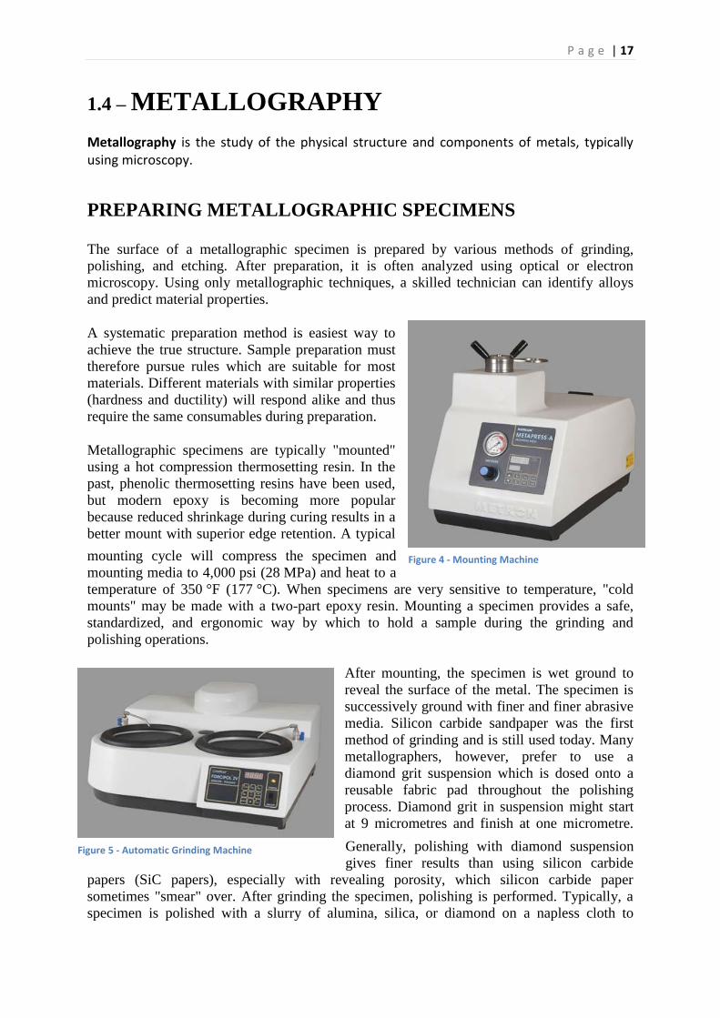
Metallographic specimens are typically "mounted"
using a hot compression thermosetting resin. In the
past, phenolic thermosetting resins have been used,
but modern epoxy is becoming more popular
because reduced shrinkage during curing results in a
better mount with superior edge retention. A typical
mounting cycle will compress the specimen and
mounting media to 4,000 psi (28 MPa) and heat to a
temperature of 350 °F (177 °C). When specimens are very sensitive to temperature, "cold
mounts" may be made with a two-part epoxy resin. Mounting a specimen provides a safe,
standardized, and ergonomic way by which to hold a sample during the grinding and
polishing operations.
After mounting, the specimen is wet ground to
reveal the surface of the metal. The specimen is
successively ground with finer and finer abrasive
media. Silicon carbide sandpaper was the first
method of grinding and is still used today. Many
metallographers, however, prefer to use a
diamond grit suspension which is dosed onto a
reusable fabric pad throughout the polishing
process. Diamond grit in suspension might start
at 9 micrometres and finish at one micrometre.
Generally, polishing with diamond suspension
gives finer results than using silicon carbide
papers (SiC papers), especially with revealing porosity, which silicon carbide paper
sometimes "smear" over. After grinding the specimen, polishing is performed. Typically, a
specimen is polished with a slurry of alumina, silica, or diamond on a napless cloth to
Figure 4 - Mounting Machine
Figure 5 - Automatic Grinding Machine

P a g e | 18
produce a scratch-free mirror finish, free from smear, drag, or pull-outs and with minimal
deformation remaining from the preparation process.
After polishing, certain microstructural constituents can be seen with the microscope, e.g.,
inclusions and nitrides. If the crystal structure is non-cubic (e.g., a metal with a hexagonal-
closed packed crystal structure, such as Ti or Zr) the microstructure can be revealed without
etching using crossed polarized light (light microscopy). Otherwise, the microstructural
constituents of the specimen are revealed by using a suitable chemical or electrolytic etchant.
A great many etchants have been developed to reveal the structure of metals and alloys,
ceramics, carbides, nitrides, and so forth. While a number of etchants may work for a given
metal or alloy, they generally produce different results, in that some etchants may reveal the
general structure, while others may be selective to certain phases or constituents.
1.5 – ROCKWELL HARDNESS TESTER
The Rockwell scale is a hardness scale based on the indentation hardness of a material. The
Rockwell test determines the hardness by measuring the depth of penetration of an indenter
under a large load compared to the penetration made by a preload. There are different scales,
which are denoted by a single letter, that use different loads or indenters. The result, which is
a dimensionless number, is noted by HRX where X is the scale letter.
When testing metals, indentation hardness correlates
linearly with tensile strength. This important relation
permits economically important nondestructive testing
of bulk metal deliveries with lightweight, even
portable equipment, such as hand-held Rockwell
hardness testers
OPERATION
The determination of the Rockwell hardness of a
material involves the application of a minor load
followed by a major load, and then noting the depth of
penetration, hardness value directly from a dial, in
which a harder material gives a higher number. The
chief advantage of Rockwell hardness is its ability to
display hardness values directly, thus obviating
tedious calculations involved in other hardness
measurement techniques.
It is typically used in engineering and metallurgy. Its commercial popularity arises from its
speed, reliability, robustness, resolution and small area of indentation.
In order to get a reliable reading the thickness of the test-piece should be at least 10 times the
depth of the indentation. Also, readings should be taken from a flat perpendicular surface,
Figure 6 - Rockwell Hardness Tester
P a g e | 19
because round surfaces give lower readings. A correction factor can be used if the hardness
must be measured on a round surface.
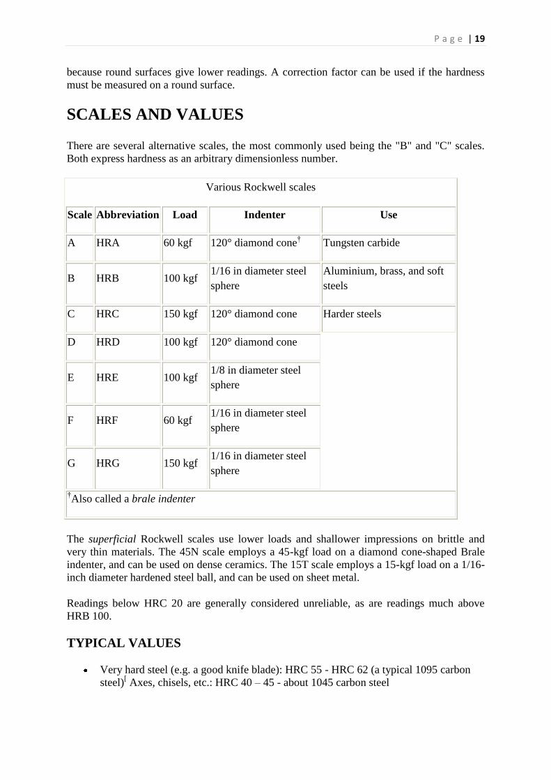
SCALES AND VALUES
There are several alternative scales, the most commonly used being the "B" and "C" scales.
Both express hardness as an arbitrary dimensionless number.
Various Rockwell scales
Scale Abbreviation Load Indenter Use
A HRA 60 kgf 120° diamond cone† Tungsten carbide
B HRB 100 kgf 1/16 in diameter steel
sphere
Aluminium, brass, and soft
steels
C HRC 150 kgf 120° diamond cone Harder steels
D HRD 100 kgf 120° diamond cone
E HRE 100 kgf 1/8 in diameter steel
sphere
F HRF 60 kgf 1/16 in diameter steel
sphere
G HRG 150 kgf 1/16 in diameter steel
sphere
†Also called a brale indenter
The superficial Rockwell scales use lower loads and shallower impressions on brittle and
very thin materials. The 45N scale employs a 45-kgf load on a diamond cone-shaped Brale
indenter, and can be used on dense ceramics. The 15T scale employs a 15-kgf load on a 1/16-
inch diameter hardened steel ball, and can be used on sheet metal.
Readings below HRC 20 are generally considered unreliable, as are readings much above
HRB 100.
TYPICAL VALUES
Very hard steel (e.g. a good knife blade): HRC 55 - HRC 62 (a typical 1095 carbon
steel)[ Axes, chisels, etc.: HRC 40 – 45 - about 1045 carbon steel
P a g e | 20
Several other scales, including the extensive A-scale, are used for specialized
applications. There are special scales for measuring case-hardened specimens.
1.6 - X-RAY FLUORESCENCE (XRF)
X-ray fluorescence (XRF) is the emission of characteristic "secondary" (or fluorescent) X-
rays from a material that has been excited by bombarding with high-energy X-rays or gamma
rays. The phenomenon is widely used for elemental analysis and chemical analysis,
particularly in the investigation of metals, glass, ceramics and building materials, and for
research in geochemistry, forensic science and archaeology.
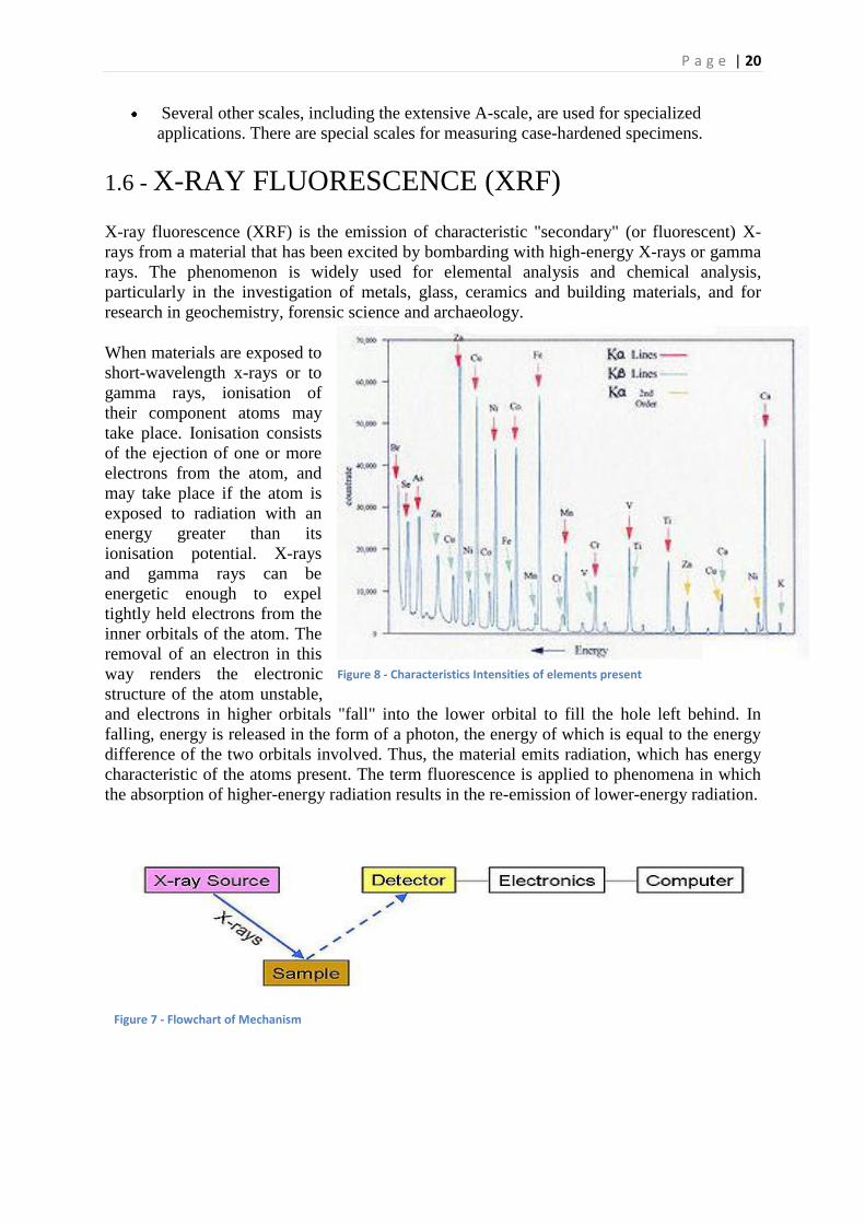
When materials are exposed to
short-wavelength x-rays or to
gamma rays, ionisation of
their component atoms may
take place. Ionisation consists
of the ejection of one or more
electrons from the atom, and
may take place if the atom is
exposed to radiation with an
energy greater than its
ionisation potential. X-rays
and gamma rays can be
energetic enough to expel
tightly held electrons from the
inner orbitals of the atom. The
removal of an electron in this
way renders the electronic
structure of the atom unstable,
and electrons in higher orbitals "fall" into the lower orbital to fill the hole left behind. In
falling, energy is released in the form of a photon, the energy of which is equal to the energy
difference of the two orbitals involved. Thus, the material emits radiation, which has energy
characteristic of the atoms present. The term fluorescence is applied to phenomena in which
the absorption of higher-energy radiation results in the re-emission of lower-energy radiation.
Figure 8 - Characteristics Intensities of elements present
Figure 7 - Flowchart of Mechanism

P a g e | 21
BASED ON ALL THE STEP-WISE EXPERIMENTAL
WORK/TECHNIQUES PERFORMED ON THE CRANKSHAFT
INCLUDING:
Photographs in as received condition,
Different heat treatments techniques performed on different
sections of crankshaft,
Hardness measurements in as received and heat treated form,
Metallography done in as received and heat treated form in
different magnifications,
Metal composition analysis i.e. Spectroscopy (XRF) done in
MMD XRF lab and from PSM,
Steel grade identification with the help of hardness,
microstructures, and composition.
P a g e | 22
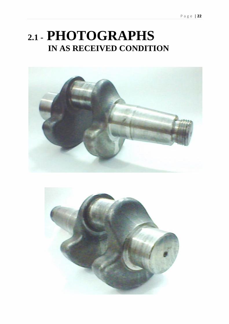
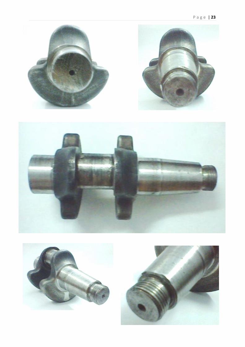
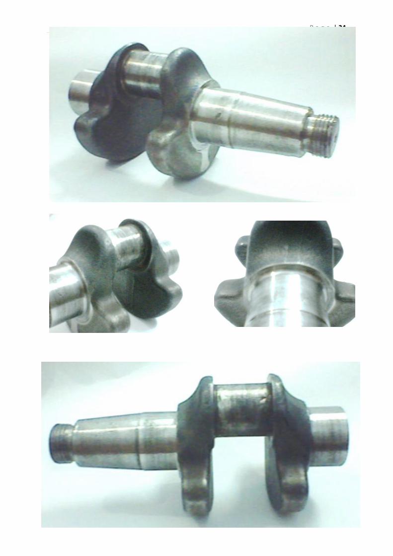
2.1 - PHOTOGRAPHS IN AS RECEIVED CONDITION
P a g e | 23
P a g e | 24
P a g e | 25
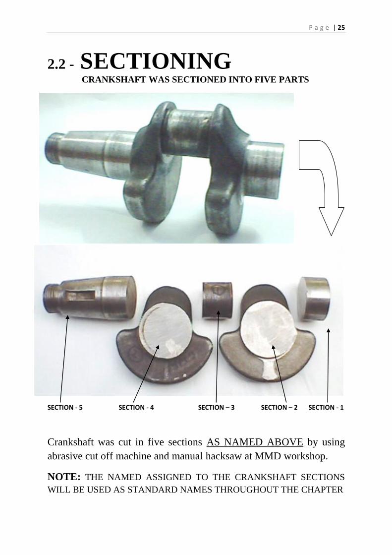
2.2 - SECTIONING CRANKSHAFT WAS SECTIONED INTO FIVE PARTS
SECTION - 5 SECTION - 4 SECTION – 3 SECTION – 2 SECTION - 1
Crankshaft was cut in five sections AS NAMED ABOVE by using
abrasive cut off machine and manual hacksaw at MMD workshop.
NOTE: THE NAMED ASSIGNED TO THE CRANKSHAFT SECTIONS
WILL BE USED AS STANDARD NAMES THROUGHOUT THE CHAPTER
P a g e | 26
P a g e | 27
2.3 - HARDNESS PROFILE IN AS RECEIVED CONDITION
EQUIPMENT: ROCKWELL HARDNESS TESTER (MMD)
More than two hardness readings were taken on serial points on all the sections (Section-1to
Section-5). These readings are given below:
SECTION – 1 71 HRB, 72 HRB, 72 HRB
SECTION – 2 68 HRB, 69 HRB
SECTION – 3 63 HRB, 60 HRB, 68 HRB
SECTION – 4 70.5 HRB, 72 HRB
SECTION – 5 60 HRB, 70 HRB, 67 HRB, 69 HRB, 64 HRB, 65 HRB, 63 HRB
Then, Hardness profile is drawn according to the order of the points from Section-1
towards Section-5.
SECTION – 1 SECTION - 5
54
56
58
60
62
64
66
68
70
72
74
H A R D N E S S
HRB
FROM SECTION-1 TOWARDS SECTION-5
P a g e | 28
2.4 - MICROSTRUCTURES
IN AS RECEIEVED CONDITION
For steel grade identification purposes the micrograph of crankshaft material was taken in
longitudinal & lateral direction and then matched with ASM Metal Handbook for steel
microstructures.
2.4.1 - IN LATERAL DIRECTION OF CRANKSHAFT:
Lateral micrographs of Section-1 was taken in three different magnifications i.e. 100x, 200x,
and 400x using 2% Nital solution. This was done in Metallography lab MMD.
MICROGRAPHS AT 100x – 2% NITAL
(a) (b)
P a g e | 29
MICROGRAPHS AT 200x – 2% NITAL
(a) (b)
MICROGRAPHS AT 400x – 2% NITAL
(a) (b)
P a g e | 30
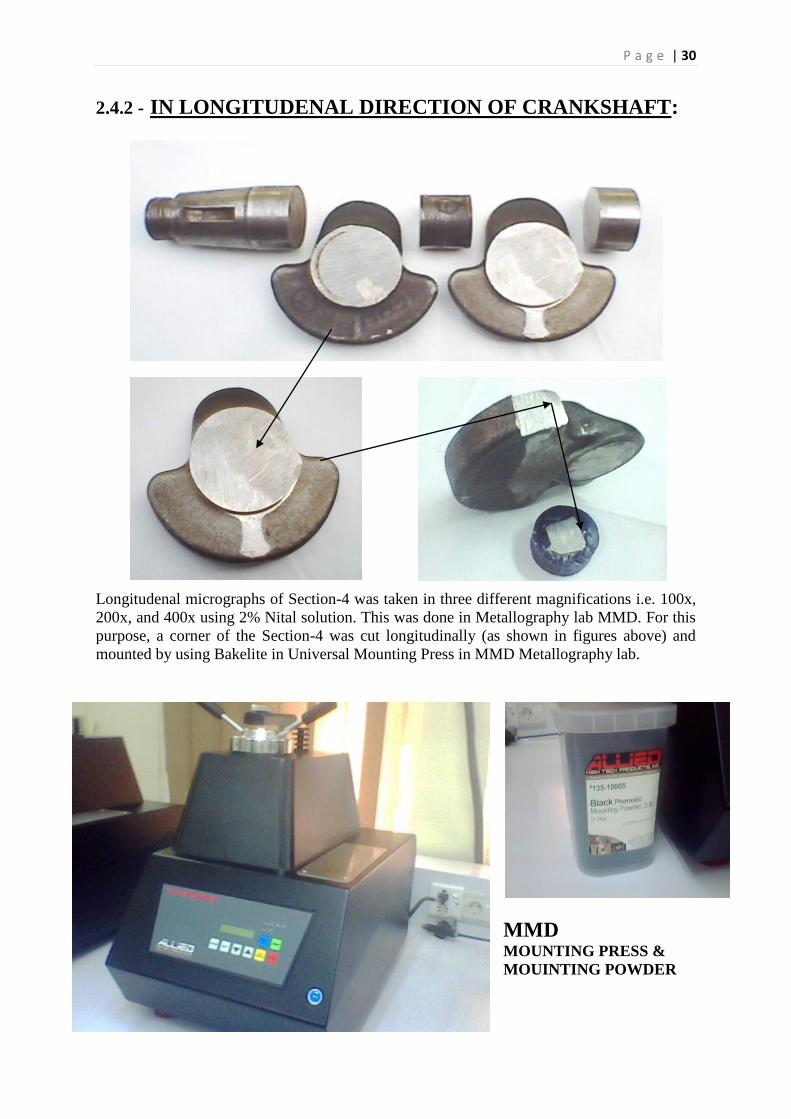
2.4.2 - IN LONGITUDENAL DIRECTION OF CRANKSHAFT:
Longitudenal micrographs of Section-4 was taken in three different magnifications i.e. 100x,
200x, and 400x using 2% Nital solution. This was done in Metallography lab MMD. For this
purpose, a corner of the Section-4 was cut longitudinally (as shown in figures above) and
mounted by using Bakelite in Universal Mounting Press in MMD Metallography lab.
MMD MOUNTING PRESS &
MOUINTING POWDER
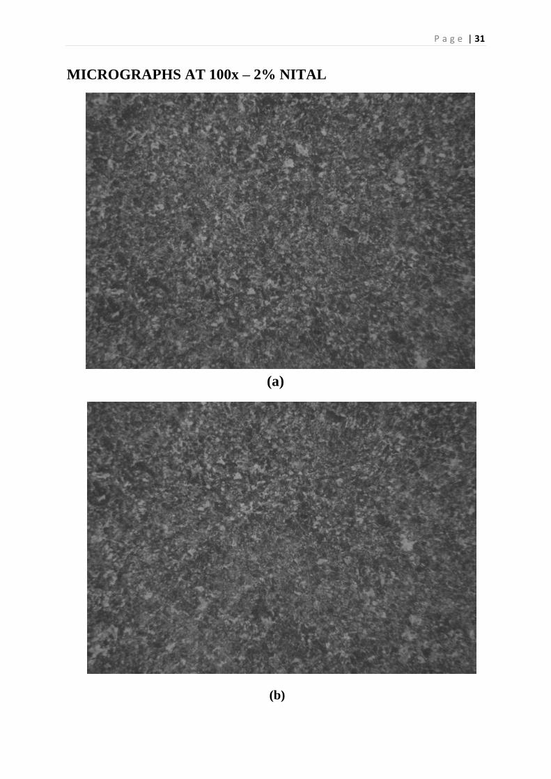
P a g e | 31
MICROGRAPHS AT 100x – 2% NITAL
(a)
(b)
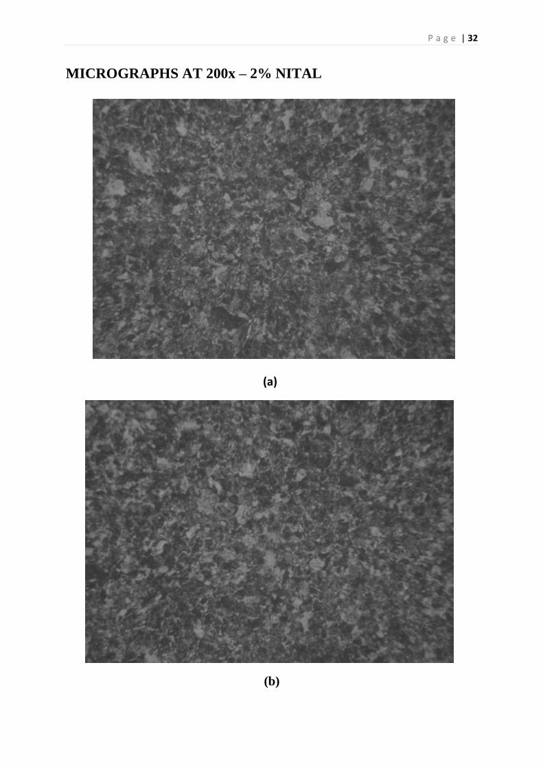
P a g e | 32
MICROGRAPHS AT 200x – 2% NITAL
(a)
(b)
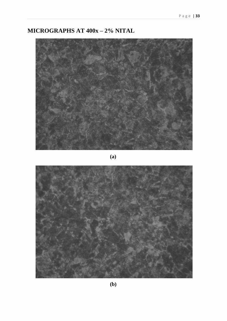
P a g e | 33
MICROGRAPHS AT 400x – 2% NITAL
(a)
(b)
P a g e | 34
2.5 - XRF ANALYSIS IN MMD XRF LAB
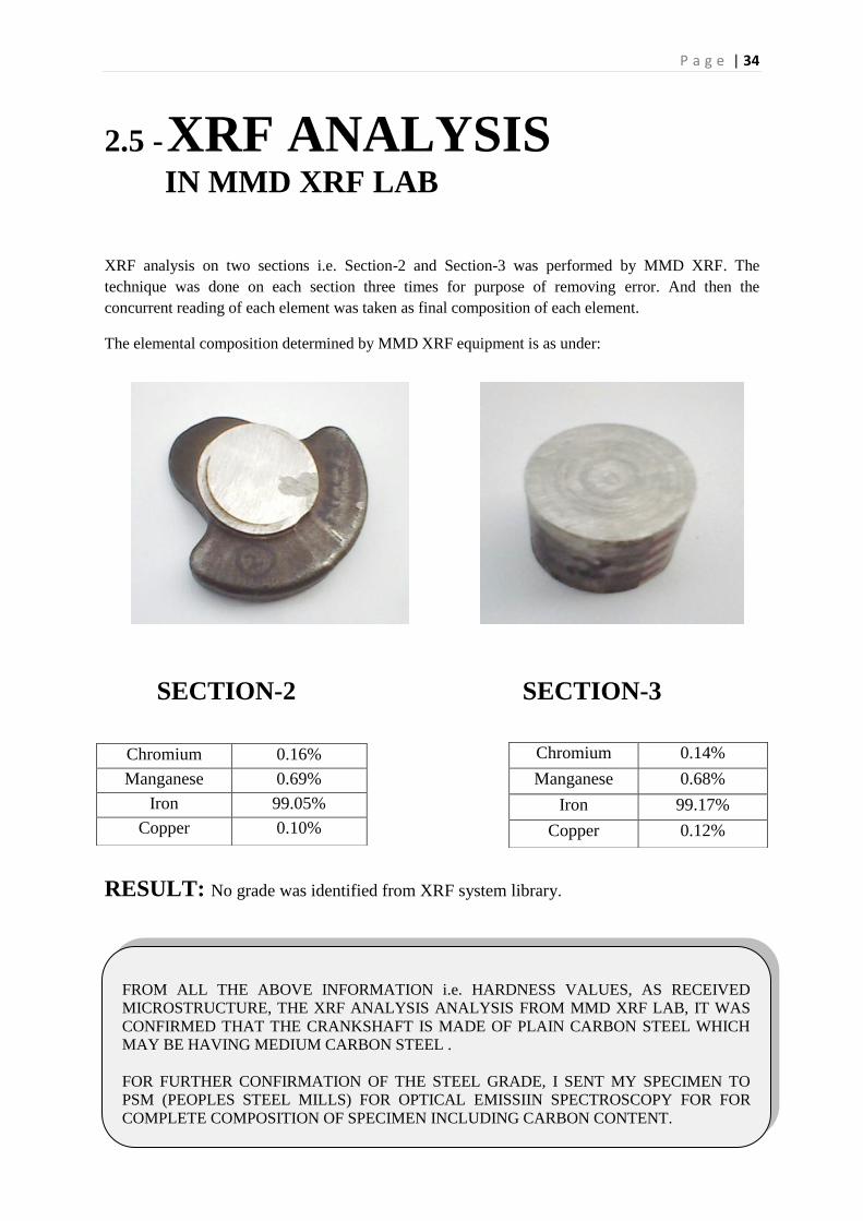
XRF analysis on two sections i.e. Section-2 and Section-3 was performed by MMD XRF. The
technique was done on each section three times for purpose of removing error. And then the
concurrent reading of each element was taken as final composition of each element.
The elemental composition determined by MMD XRF equipment is as under:
SECTION-2 SECTION-3
RESULT: No grade was identified from XRF system library.
Chromium 0.16%
Manganese 0.69%
Iron 99.05%
Copper 0.10%
Chromium 0.14%
Manganese 0.68%
Iron 99.17%
Copper 0.12%
FROM ALL THE ABOVE INFORMATION i.e. HARDNESS VALUES, AS RECEIVED
MICROSTRUCTURE, THE XRF ANALYSIS ANALYSIS FROM MMD XRF LAB, IT WAS
CONFIRMED THAT THE CRANKSHAFT IS MADE OF PLAIN CARBON STEEL WHICH
MAY BE HAVING MEDIUM CARBON STEEL .
FOR FURTHER CONFIRMATION OF THE STEEL GRADE, I SENT MY SPECIMEN TO
PSM (PEOPLES STEEL MILLS) FOR OPTICAL EMISSIIN SPECTROSCOPY FOR FOR
COMPLETE COMPOSITION OF SPECIMEN INCLUDING CARBON CONTENT.
P a g e | 35
2.6 – LIGHT EMISSION SPECTROSCOPY DONE IN PSM (PEOPLES STEEL MILL)
The complete composition of the specimen including carbon content is as follows:
Carbon 0.463 %
Silicon 0.183 %
Magnesium 0.798 %
Phosphorus 0.0139 %
Sulpher 0.0137 %
Chromium 0.162 %
Vanadium !0.001%
Molybenidium 0.012 %
Nickel 0.035 %
Tungsten !0.001%
Cobalt 0.005%
Aluminium 0.021 %
Copper 0.096 %
Lead !0.001%
Strontium 0.0058%
Antimony !0.001 %
Arsenic 0.0029%
Titanium 0.004%
Zinc !0.0001 %
Niobium 0.0007%
Boron 0.00035
Iron 98.18 %
2.7 – IDENTIFICATION
2.7.1 – GRADE
FROM ALL THE ABOVE INFORMATION, THE STEEL GRADE OF THE CRANKSHAFT
WAS IDENTIFIED AS:
AISI 1045 WHICH IS A MEDIUM CARBON STEEL IN THE CATEGORY OF PLAIN CARBON
STEEL WITH ZERO REPRESENTING NO ALLOYING ELEMENTS.
P a g e | 36
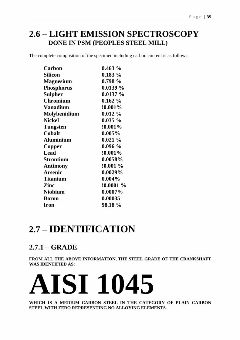
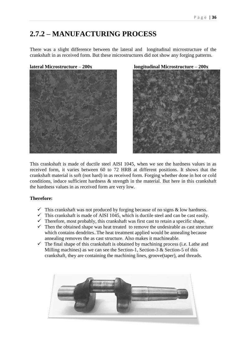
2.7.2 – MANUFACTURING PROCESS
There was a slight difference between the lateral and longitudinal microstructure of the
crankshaft in as received form. But these microstructures did not show any forging patterns.
lateral Microstructure – 200x longitudinal Microstructure – 200x
This crankshaft is made of ductile steel AISI 1045, when we see the hardness values in as
received form, it varies between 60 to 72 HRB at different positions. It shows that the
crankshaft material is soft (not hard) in as received form. Forging whether done in hot or cold
conditions, induce sufficient hardness & strength in the material. But here in this crankshaft
the hardness values in as received form are very low.
Therefore:
This crankshaft was not produced by forging because of no signs & low hardness.
This crankshaft is made of AISI 1045, which is ductile steel and can be cast easily.
Therefore, most probably, this crankshaft was first cast to retain a specific shape.
Then the obtained shape was heat treated to remove the undesirable as cast structure
which contains dendrites..The heat treatment applied would be annealing because
annealing removes the as cast structure. Also makes it machineable.
The final shape of this crankshaft is obtained by machining process (i.e. Lathe and
Milling machines) as we can see the Section-1, Section-3 & Section-5 of this
crankshaft, they are containing the machining lines, groove(taper), and threads.
P a g e | 37
2.8 – HEAT TREATMENTS PERFORMED
IN MMD HEAT TREATMENT LAB
Then the steel grade AISI 1045 was searched for heat treatment cycles and following heat
treatment techniques were performed for material’s properties investigation.
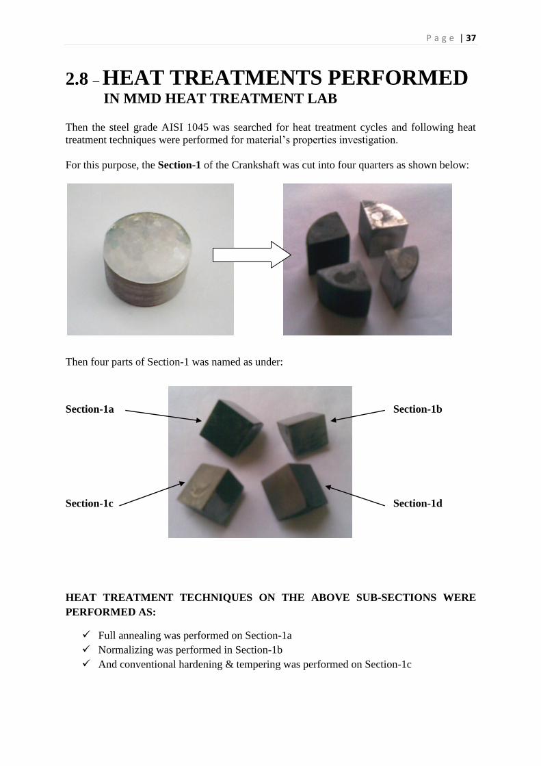
For this purpose, the Section-1 of the Crankshaft was cut into four quarters as shown below:
Then four parts of Section-1 was named as under:
Section-1a Section-1b
Section-1c Section-1d
HEAT TREATMENT TECHNIQUES ON THE ABOVE SUB-SECTIONS WERE
PERFORMED AS:
Full annealing was performed on Section-1a
Normalizing was performed in Section-1b
And conventional hardening & tempering was performed on Section-1c
P a g e | 38
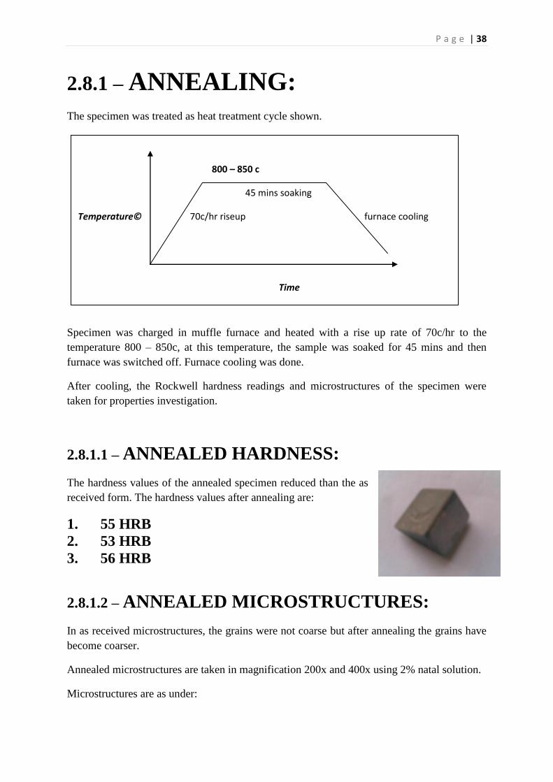
2.8.1 – ANNEALING:
The specimen was treated as heat treatment cycle shown.
Specimen was charged in muffle furnace and heated with a rise up rate of 70c/hr to the
temperature 800 – 850c, at this temperature, the sample was soaked for 45 mins and then
furnace was switched off. Furnace cooling was done.
After cooling, the Rockwell hardness readings and microstructures of the specimen were
taken for properties investigation.
2.8.1.1 – ANNEALED HARDNESS:
The hardness values of the annealed specimen reduced than the as
received form. The hardness values after annealing are:
1. 55 HRB
2. 53 HRB
3. 56 HRB
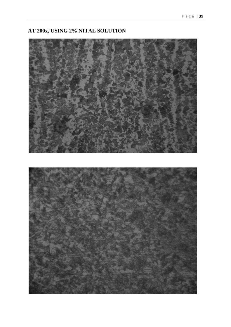
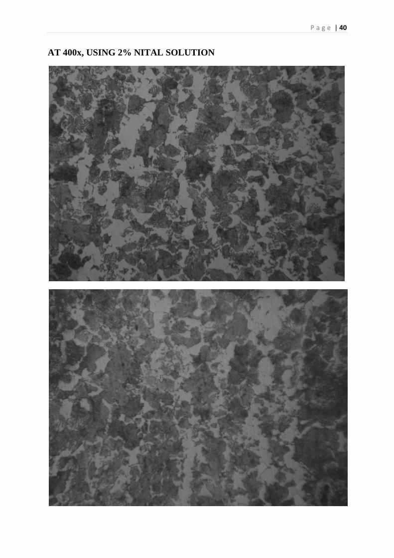
2.8.1.2 – ANNEALED MICROSTRUCTURES:
In as received microstructures, the grains were not coarse but after annealing the grains have
become coarser.
Annealed microstructures are taken in magnification 200x and 400x using 2% natal solution.
Microstructures are as under:
800 – 850 c
45 mins soaking
Temperature© 70c/hr riseup furnace cooling
Time
P a g e | 39
AT 200x, USING 2% NITAL SOLUTION
P a g e | 40
AT 400x, USING 2% NITAL SOLUTION
P a g e | 41
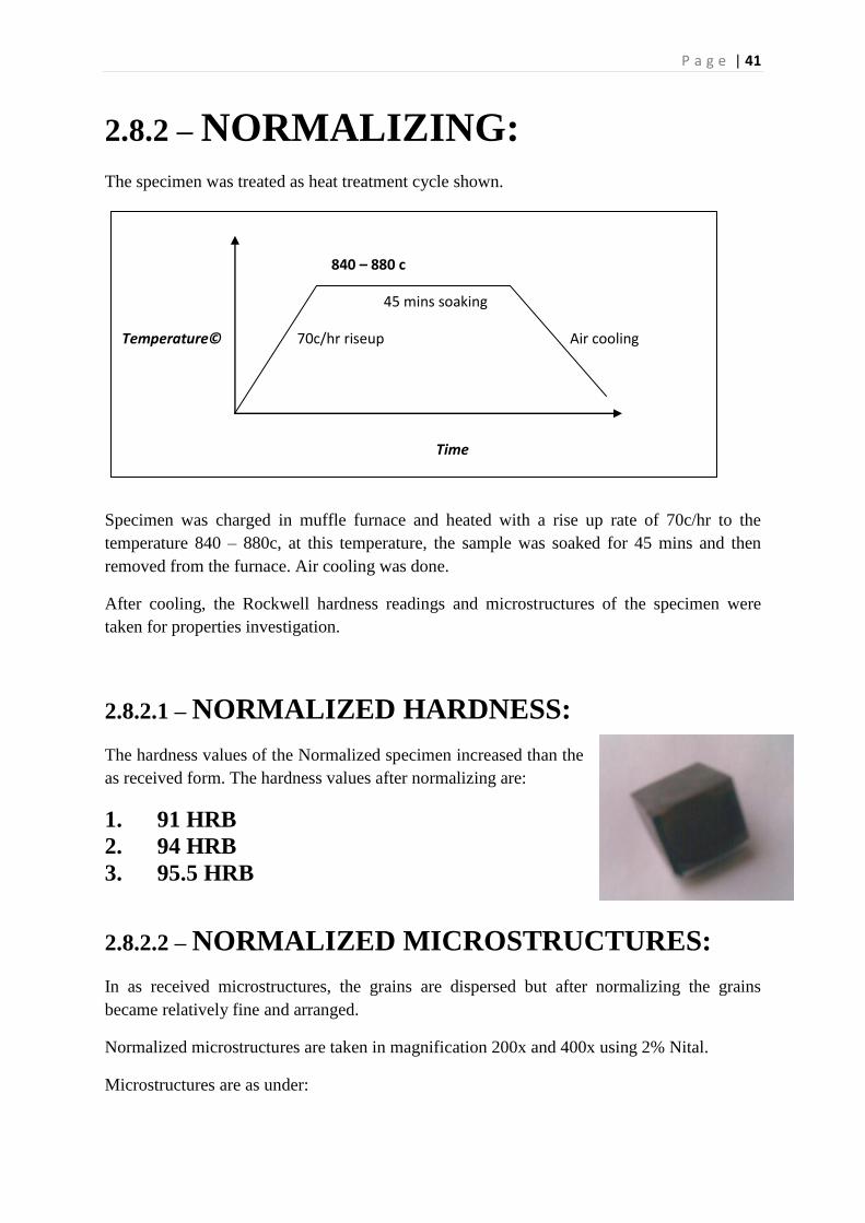
2.8.2 – NORMALIZING:
The specimen was treated as heat treatment cycle shown.
Specimen was charged in muffle furnace and heated with a rise up rate of 70c/hr to the
temperature 840 – 880c, at this temperature, the sample was soaked for 45 mins and then
removed from the furnace. Air cooling was done.
After cooling, the Rockwell hardness readings and microstructures of the specimen were
taken for properties investigation.
2.8.2.1 – NORMALIZED HARDNESS:
The hardness values of the Normalized specimen increased than the
as received form. The hardness values after normalizing are:
1. 91 HRB
2. 94 HRB
3. 95.5 HRB
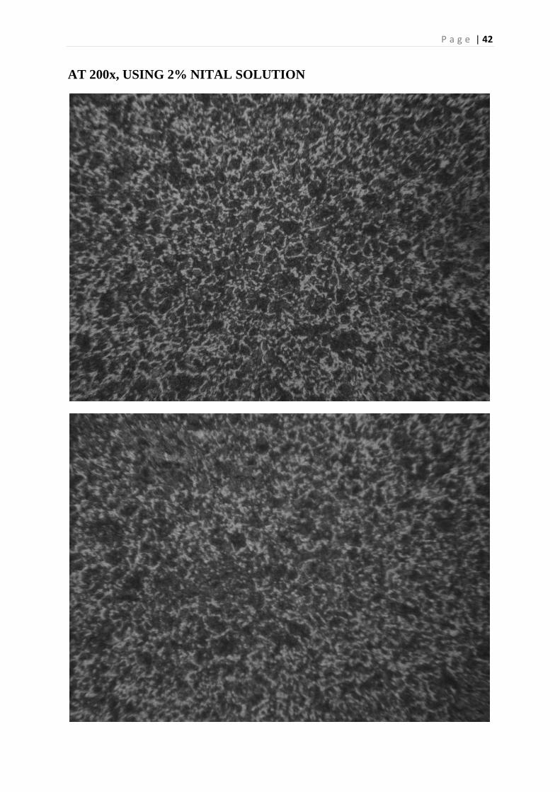
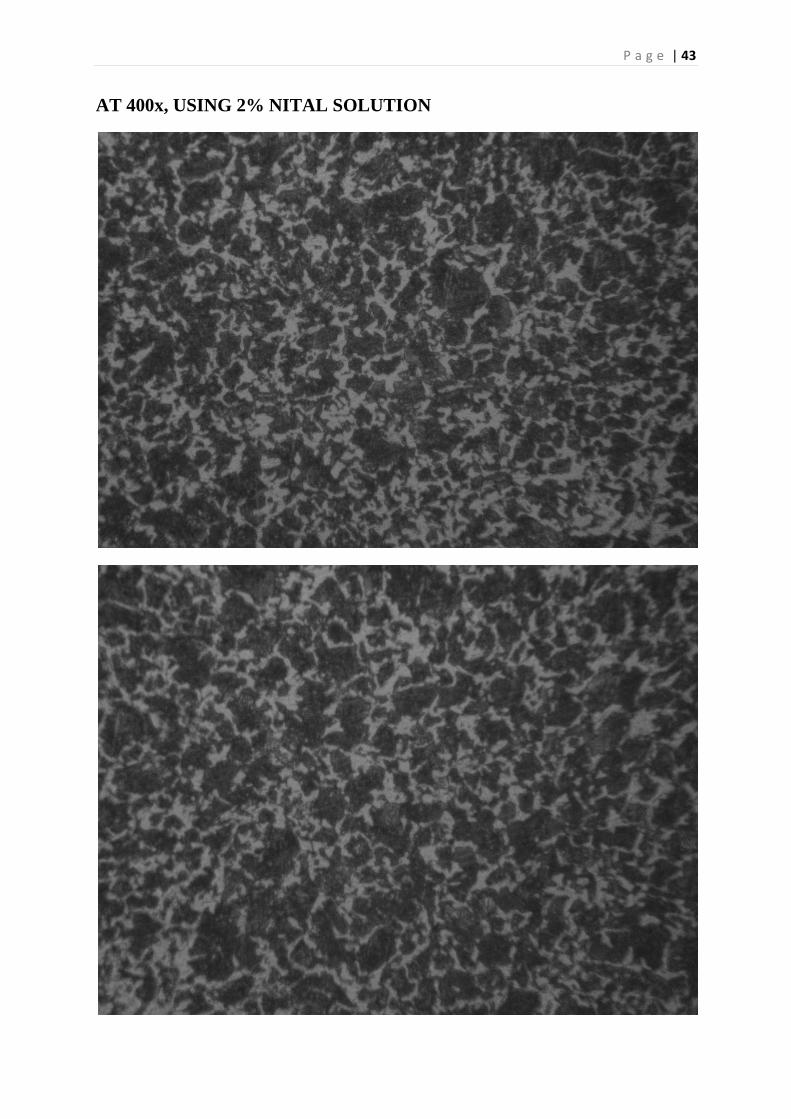
2.8.2.2 – NORMALIZED MICROSTRUCTURES:
In as received microstructures, the grains are dispersed but after normalizing the grains
became relatively fine and arranged.
Normalized microstructures are taken in magnification 200x and 400x using 2% Nital.
Microstructures are as under:
840 – 880 c
45 mins soaking
Temperature© 70c/hr riseup Air cooling
Time
P a g e | 42
AT 200x, USING 2% NITAL SOLUTION
P a g e | 43
AT 400x, USING 2% NITAL SOLUTION
P a g e | 44
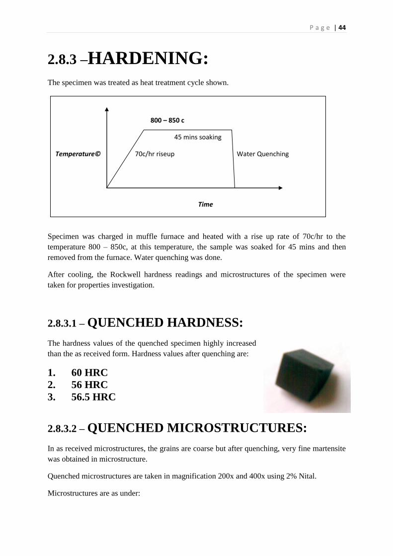
2.8.3 –HARDENING:
The specimen was treated as heat treatment cycle shown.
Specimen was charged in muffle furnace and heated with a rise up rate of 70c/hr to the
temperature 800 – 850c, at this temperature, the sample was soaked for 45 mins and then
removed from the furnace. Water quenching was done.
After cooling, the Rockwell hardness readings and microstructures of the specimen were
taken for properties investigation.
2.8.3.1 – QUENCHED HARDNESS:
The hardness values of the quenched specimen highly increased
than the as received form. Hardness values after quenching are:
1. 60 HRC
2. 56 HRC
3. 56.5 HRC
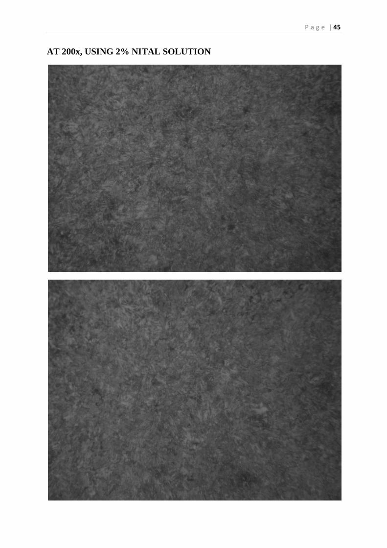
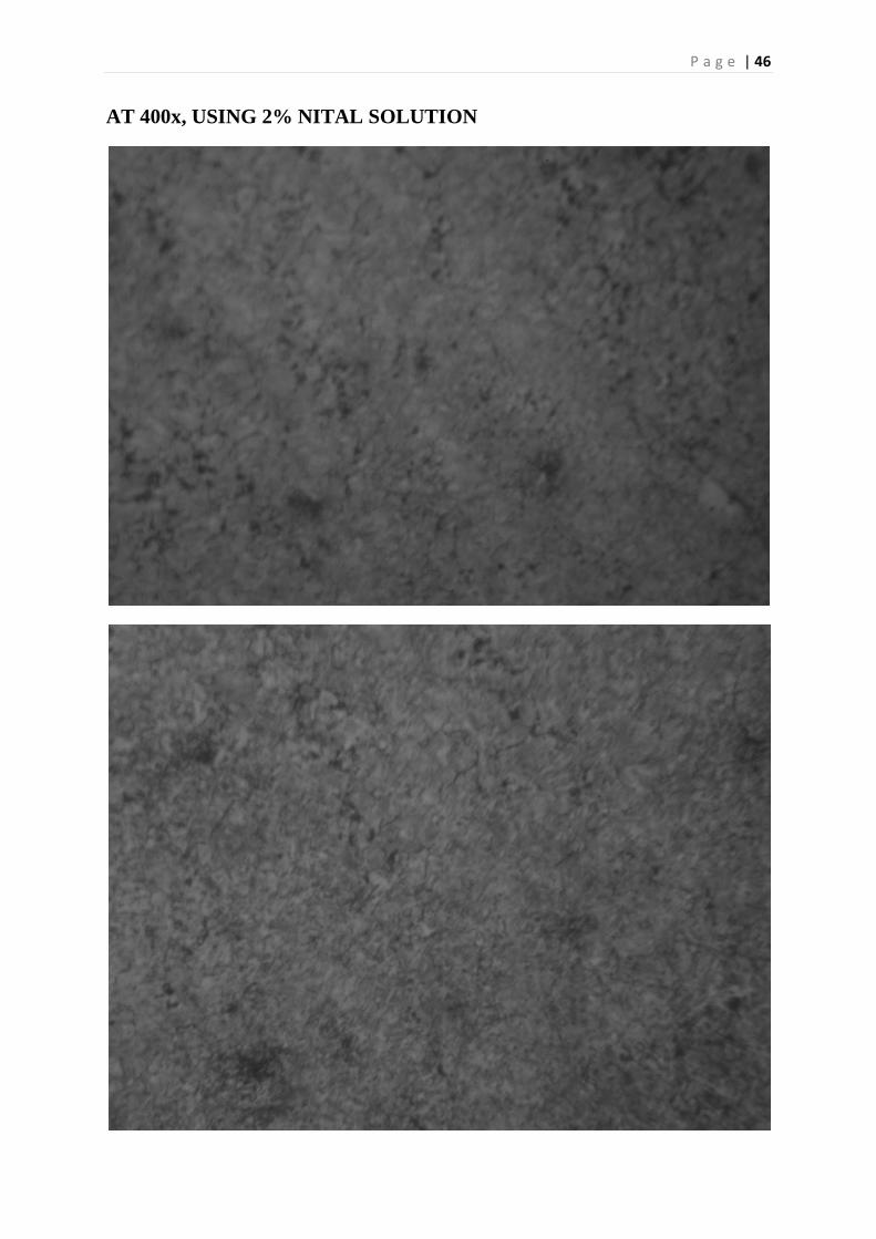
2.8.3.2 – QUENCHED MICROSTRUCTURES:
In as received microstructures, the grains are coarse but after quenching, very fine martensite
was obtained in microstructure.
Quenched microstructures are taken in magnification 200x and 400x using 2% Nital.
Microstructures are as under:
800 – 850 c
45 mins soaking
Temperature© 70c/hr riseup Water Quenching
Time
P a g e | 45
AT 200x, USING 2% NITAL SOLUTION
P a g e | 46
AT 400x, USING 2% NITAL SOLUTION
P a g e | 47
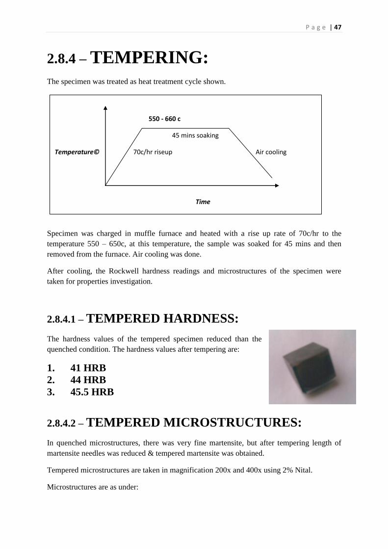
2.8.4 – TEMPERING:
The specimen was treated as heat treatment cycle shown.
Specimen was charged in muffle furnace and heated with a rise up rate of 70c/hr to the
temperature 550 – 650c, at this temperature, the sample was soaked for 45 mins and then
removed from the furnace. Air cooling was done.
After cooling, the Rockwell hardness readings and microstructures of the specimen were
taken for properties investigation.
2.8.4.1 – TEMPERED HARDNESS:
The hardness values of the tempered specimen reduced than the
quenched condition. The hardness values after tempering are:
1. 41 HRB
2. 44 HRB
3. 45.5 HRB
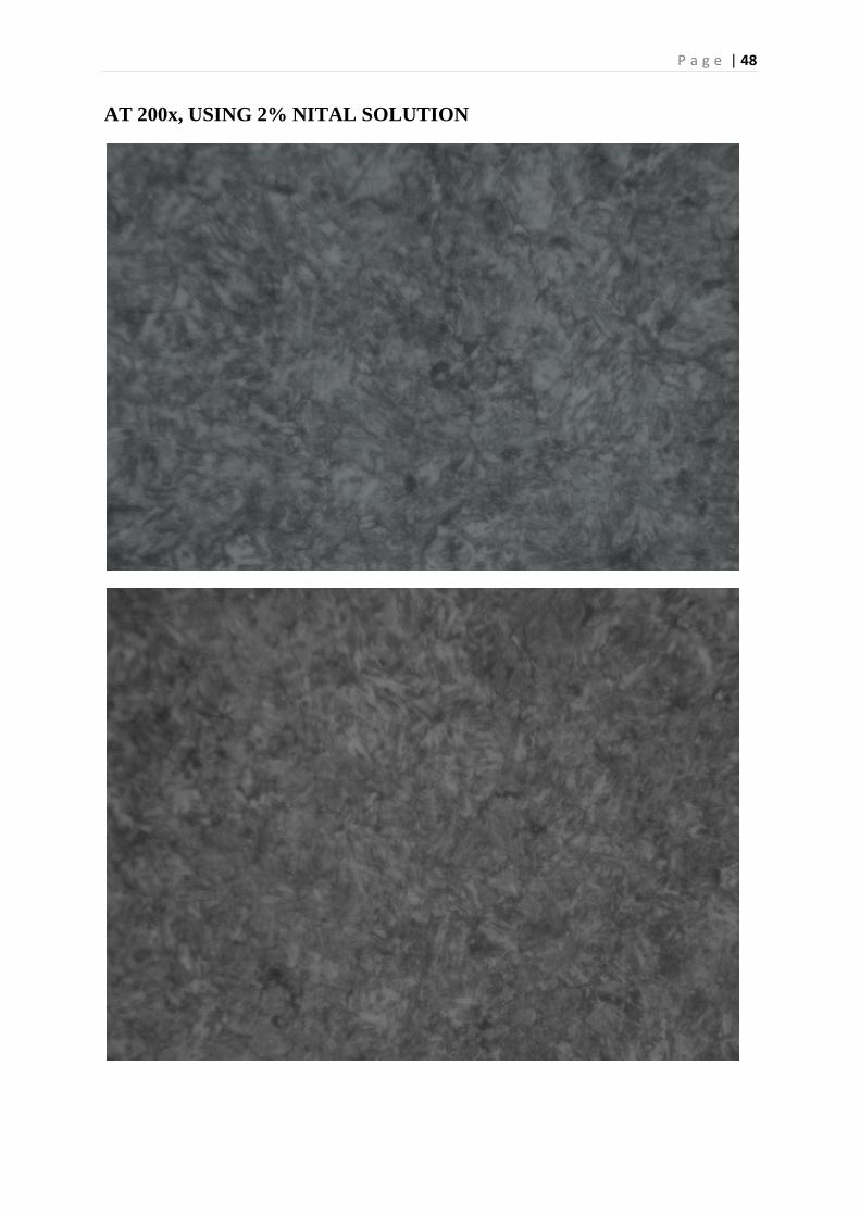
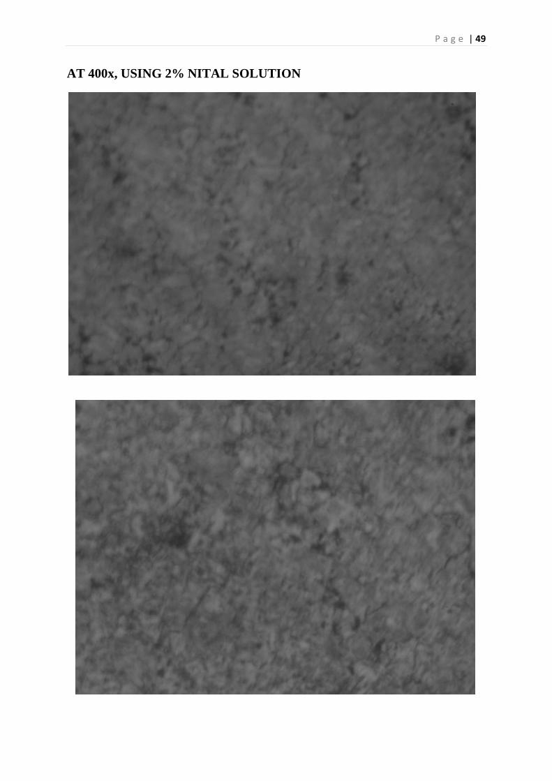
2.8.4.2 – TEMPERED MICROSTRUCTURES:
In quenched microstructures, there was very fine martensite, but after tempering length of
martensite needles was reduced & tempered martensite was obtained.
Tempered microstructures are taken in magnification 200x and 400x using 2% Nital.
Microstructures are as under:
550 - 660 c
45 mins soaking
Temperature© 70c/hr riseup Air cooling
Time
P a g e | 48
AT 200x, USING 2% NITAL SOLUTION
P a g e | 49
AT 400x, USING 2% NITAL SOLUTION
P a g e | 50
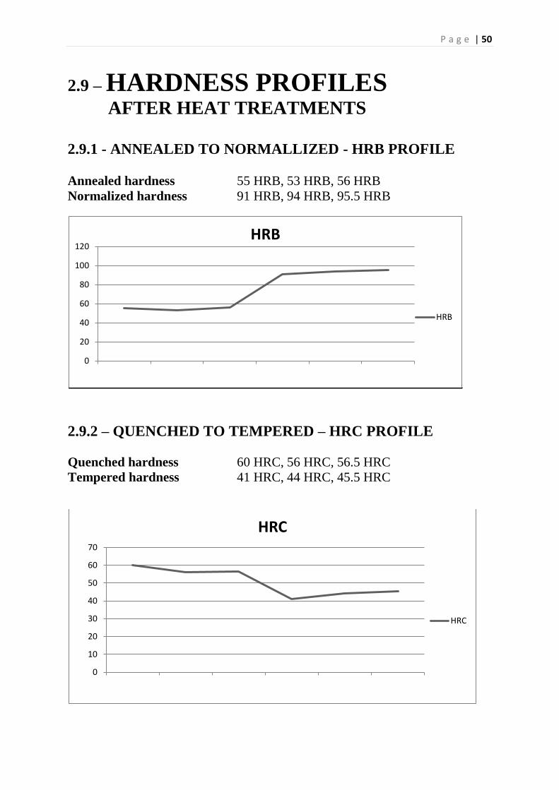
2.9 – HARDNESS PROFILES AFTER HEAT TREATMENTS
2.9.1 - ANNEALED TO NORMALLIZED - HRB PROFILE Annealed hardness 55 HRB, 53 HRB, 56 HRB
Normalized hardness 91 HRB, 94 HRB, 95.5 HRB
2.9.2 – QUENCHED TO TEMPERED – HRC PROFILE
Quenched hardness 60 HRC, 56 HRC, 56.5 HRC
Tempered hardness 41 HRC, 44 HRC, 45.5 HRC
0
20
40
60
80
100
120HRB
HRB
0
10
20
30
40
50
60
70
HRC
HRC

P a g e | 51
SUMMARY
This report consists of two chapters.
3. Theorotical Aspect
4. Practical work
The first chapter of the report comprises to all the theoretical knowledge about
the techniques, processes, and equipments used in this Reverse engineering
project. This chapter mainly includes:
Introduction to Crankshaft
Some properties of AISI 1045 Plain Carbon Steel
Literature about the Heat treatment techniques, which applied on
Crankshaft specimens
Some knowledge about the Metallography, Rockwell hardness Tester,
XRF technique which were the basis of all the project
The second chapter which is the back bone of this report, includes all the
practical performance done during all this project. It starts from selection of a
finished part (Crankshaft) to the identification of the steel grade used in that
crankshaft and further goes towards the material’s properties investigation
techniques that is heat treatments, Metallography, hardnessmeasurements etc.
the second chaptermainly includes:
Photographs in as received condition,
Different heat treatments techniques performed on different sections of
crankshaft,
Hardness measurements in as received and heat treated form,
Metallography done in as received and heat treated form in different
magnifications,
Metal composition analysis i.e. Spectroscopy (XRF) done in MMD XRF
lab and from PSM,
Steel grade identification with the help of hardness, microstructures, and
composition.
Moreover the report contains a comprehensive knowledge about all the steps
and procedures during the entire project. I hope the reader would be quite
pleasant to see and read this report.
P a g e | 52
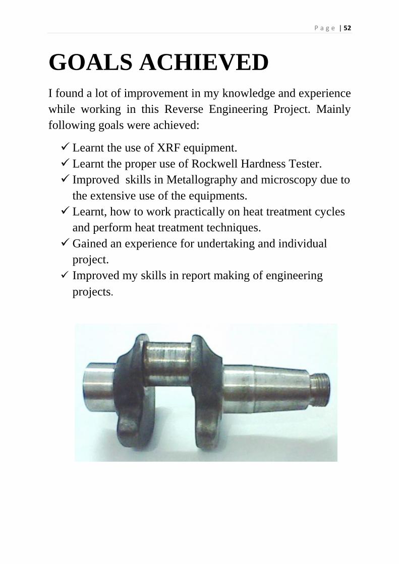
GOALS ACHIEVED
I found a lot of improvement in my knowledge and experience
while working in this Reverse Engineering Project. Mainly
following goals were achieved:
Learnt the use of XRF equipment.
Learnt the proper use of Rockwell Hardness Tester.
Improved skills in Metallography and microscopy due to
the extensive use of the equipments.
Learnt, how to work practically on heat treatment cycles
and perform heat treatment techniques.
Gained an experience for undertaking and individual
project.
Improved my skills in report making of engineering
projects.