Embed Size (px)
Citation preview
DOT/FAA/TC-15/27 Federal Aviation Administration William J. Hughes Technical Center Aviation Research Division Atlantic City International Airport New Jersey 08405
Reverse Engineering for Software and Digital Systems February 2016 Final Report This document is available to the U.S. public through the National Technical Information Service (NTIS), Springfield, Virginia 22161. This document is also available from the Federal Aviation Administration William J. Hughes Technical Center at actlibrary.tc.faa.gov.
U.S. Department of Transportation Federal Aviation Administration
NOTICE
This document is disseminated under the sponsorship of the U.S. Department of Transportation in the interest of information exchange. The U.S. Government assumes no liability for the contents or use thereof. The U.S. Government does not endorse products or manufacturers. Trade or manufacturers’ names appear herein solely because they are considered essential to the objective of this report. The findings and conclusions in this report are those of the author(s) and do not necessarily represent the views of the funding agency. This document does not constitute FAA policy. Consult the FAA sponsoring organization listed on the Technical Documentation page as to its use. This report is available at the Federal Aviation Administration William J. Hughes Technical Center’s Full-Text Technical Reports page: actlibrary.tc.faa.gov in Adobe Acrobat portable document format (PDF).
Technical Report Documentation Page 1. Report No. DOT/FAA/TC-15/27
2. Government Accession No. 3. Recipient's Catalog No.
4. Title and Subtitle REVERSE ENGINEERING FOR SOFTWARE AND DIGITAL SYSTEMS
5. Report Date February 2016
6. Performing Organization Code
7. Author(s) George Romanski1, Mike DeWalt2 for phase 1 – research, and Dewi Daniels3for phase 2 – Validation.
8. Performing Organization Report No.
9. Performing Organization Name and Address 1Verocel, Inc. 234 Littleton Road, Suite 2B, Westford MA 01886
10. Work Unit No. (TRAIS)
2Certification Services, Inc., P.O. Box 1569, Eastsound, WA 98245-1569 3Verocel Limited, 129 Devizes Road, Hilperton, Trowbridge, UK, BA14 7AZ
11. Contract or Grant No. DTFACT-09-C-00023
12. Sponsoring Agency Name and Address U.S. Department of Transportation Federal Aviation Administration 950 L’Enfant Plaza SW, 5th Floor Washington, DC 20024
13. Type of Report and Period Covered Final Report
14. Sponsoring Agency Code AIR-134
15. Supplementary Notes The Federal Aviation Administration William J. Hughes Technical Center Aviation Research Division COR was Charles Kilgore. 16. Abstract Reverse engineering (RE) is a class of development processes that starts with detailed representations of system software or hardware description for a device and applies various techniques to produce more generalized, less-detailed representations. The goal is to have more abstract representations that can be used to understand and consider the structure and intent of the more detailed representations. RE has been used in many industries, including aircraft applications for mechanical, hardware and software components. The scope of this report covers RE software and electronic hardware device applications for airborne systems and equipment. The Federal Aviation Administration sponsored this research project to provide a clear understanding of what should be considered RE for airborne software and airborne electronic hardware (AEH) devices and under what conditions it could be deployed or restricted in the aircraft certification environment. This report provides an overview of the aviation industry’s views of RE, the potential issues of employing RE for safety-critical airborne systems, recommendations for when RE application is acceptable, and some associated criteria for successful implementation. The RE development process is the opposite of the traditional waterfall model that has been a well-known commodity to the certification authorities; therefore, RE, which is much less known, poses a concern to the certification authorities. Without a common set of recognized and accepted terminology, definitions, and constraints on the processes and other issues, the certification authorities are forced to provide case-by-case evaluations of the different RE proposals. This report provides the research results for RE. The intended audience includes practitioners who develop compliance evidence, as well as evaluators for airborne software and AEH to be approved under RTCA documents DO-178B and DO-254, respectively. The report proposes a framework for RE of software and electronic hardware for airborne systems and equipment. This report also validates that framework by presenting two case studies. The software case study chosen is a subset of an Ada runtime library. This library was chosen because it is distributed under the GNU General Public License and because it has previously been approved to DO-178B Level A as part of a specific aircraft project. The AEH case study was based on the certification of a system with two programmable logic devices. The intent of these case studies was to validate the framework against two examples that were developed using RE and approved by the FAA. 17. Key Words Reverse engineering, Software, DO-178, CAST-18, DO-254, Complex electronic devices
18. Distribution Statement This document is available to the U.S. public through the National Technical Information Service (NTIS), Springfield, Virginia 22161. This document is also available from the Federal Aviation Administration William J. Hughes Technical Center at actlibrary.tc.faa.gov.
19. Security Classif. (of this report) Unclassified
20. Security Classif. (of this page) Unclassified
21. No. of Pages 120
22. Price
Form DOT F 1700.7 (8-72) Reproduction of completed page authorized

ACKNOWLEDGEMENTS
We would like to thank Kelly Hayhurst from the NASA Langley Research Center for her valuable contribution to the survey. We also thank the Federal Aviation Administration Review Team, consisting of Barbara Lingberg, Charles Kilgore, Richard Spencer, Srini Mandalapu, and Will Struck, for their technical support and guidance throughout the project.
iii
TABLE OF CONTENTS
EXECUTIVE SUMMARY viii
1. INTRODUCTION 1
1.1 Background 1 1.2 Purpose and Scope 2
1.2.1 Why is This Report Needed? 2 1.2.2 Intent of the Report 3
1.3 Section Overviews 4
2. SURVEY AND INDUSTRY EXPERIENCE 5
2.1 Industry experience 5 2.2 Industry perspective from survey 5
2.2.1 Software Survey Results 5 2.2.2 CEH Survey Results 6
2.3 Terminology 7
2.3.1 Reverse Engineering 7 2.3.2 Configuration Management of Reverse Engineered Artifacts 8 2.3.3 Certifier 8 2.3.4 Forward Engineering 8
3. FRAMEWORK FOR PERFORMING RE 9
3.1 Software Development Processes and Sequence Dependencies 9 3.2 Compatibility of Regulatory Guidance With RE Processes 9 3.3 Roles 12 3.4 Processes 13
3.4.1 An Example of Source Code to LLR Development 13 3.4.2 Generic RE Processes 15 3.4.3 Inputs 15 3.4.4 Outputs 16 3.4.5 Entry Criteria 17 3.4.6 Exit Criteria 17 3.4.7 Process Description 18
3.5 The RE Aspects of Software Verification 18 3.6 Generic RE SME Verification Process 20
iv
3.6.1 Inputs 20 3.6.2 Outputs 21 3.6.3 Entry Criteria 21 3.6.4 Exit Criteria 22 3.6.5 Process Description 22
3.7 Acceptance Criteria 22
4. VALIDATION OF FRAMEWORK 23
5. RECOMMENDATIONS 23
6. CONCLUSIONS 25
7. REFERENCES 25
APPENDICES A—CASE STUDY: ANALYSIS OF PROJECTS COMPLETED AT VEROCEL B—REVERSE ENGINEERING SURVEY C—REVERSE ENGINEERING SURVEY RESULTS
D—ANALYSIS OF ISSUES AND THEIR POTENTIAL MITIGATIONS E—VALIDATION OF FRAMEWORK FOR SOFTWARE F—VALIDATION OF FRAMEWORK FOR AIRBORNE ELECTRONIC HARDWARE
v

LIST OF FIGURES
Figure Page 1 Example processes for development and review of LLRs using RE 14
2 Generic processes for development and review of different abstraction layers 15
vi
LIST OF ACRONYMS
A/D Analog/digital AEH Airborne electronic hardware (includes complex electronic hardware and simple
electronic hardware) ARTE Ada Runtime Environment CAST Certification Authorities Software Team CEH Complex electronic hardware COTS Commercial off-the-shelf DER Designated engineering representative DOD Department of Defense DVD-ROM Digital Versatile Disc – Read-Only Memory ELOC Effective lines of code FAA Federal Aviation Administration GNAT GNU New York University Ada 9X Translator GNU A recursive acronym for “GNU’s Not Unix!”—Unix-like computer operation
system developed by the GNU Project GPL General Public License HAS Hardware accomplishment summary HIS High integrity software HLR High-level requirement ICU Interface Control Unit KLOC Kilo (thousand) lines of code LAL Less abstract layer LLR Low-level requirement MAL More abstract layer NaN Not a number PHAC Plan for Hardware Aspects of Certification PLD Programmable logic device PR Problem report PSAC Plan for Software Aspects of Certification RE Reverse engineering RESP Reverse Engineering Software Plan SAS Software Accomplishment Summary SDP Software Development Plan SME Subject matter expert SOI Stage of involvement SUNECO Training aid identifying the combination of SUfficient, NEcessary, and COrrect TSO Technical Standard Order UAS Unmanned aircraft system VHDL Very High Speed Integrated Circuit (VHSIC) Hardware Description Language
vii
EXECUTIVE SUMMARY
Reverse Engineering (RE) is a class of development processes that start with detailed representations of software for a system, or a hardware description for a device, and apply various techniques to produce more generalized, less detailed representations. The goal is to have more abstract representations that can be used to understand and consider the structure and intent of the more detailed representations. RE has been used in many industries, including aircraft applications for mechanical, hardware, and software components. The scope of this report is the electronic hardware devices and software applications of RE for airborne systems and equipment.
The Federal Aviation Administration (FAA) sponsored this research task to provide a clear understanding of what should be considered acceptable RE for airborne software and airborne electronic hardware (AEH) devices, and under what conditions it could be deployed or restricted in the aircraft certification environment. The report is designed to provide an overview of the aviation industry’s views of RE, potential issues of employing RE for safety critical aviation systems, recommendations for when application of RE is acceptable, and some associated criteria for successful implementation.
The RE development process is of concern to the certification authorities because it is opposite of the traditional waterfall model that has been a well-known commodity. Without a common set of recognized and accepted terminology, definitions, and constraints on the processes and other issues, the certification authorities are forced to provide case-by-case evaluations of the different RE proposals.
This report provides the research results of the RE development process. The intended audience includes practitioners (who develop compliance evidence) and evaluators so airborne software and AEH can be approved under RTCA documents DO-178B and DO-254, respectively. This report may be used to obtain:
• A view of how others in the aviation industry understand and use RE. This includes analysis of views held by software and electronic hardware developers, certification authorities, and designated engineering representatives (DERs).
• A consistent and uniform view of RE developed from industry experience, industry perspective, and research within the field.
• Insight into the software planning processes that may need to be adjusted in support of RE. As RE is a development process, planning processes may need adjustment to ensure the integrity of the process steps.
• Insight into verification processes may also need adjustment to ensure that the resulting life cycle data satisfies the objectives of DO-178B and DO-254.
• Awareness of potential hazards and risks to a project if RE is used without ensuring various safeguards are employed. If information is misused in an RE process, certain
viii

faults or errors could be concealed and could remain as latent faults or errors. By exposing the potential vulnerabilities, the process activities could be adjusted to mitigate the potential hazards, risks, and errors.
• Additional objectives and activities, or constraints on the current objectives and activities, could ensure that the use of RE is consistent with airworthiness requirements.
This research used historical data from certification projects conducted by Verocel, Inc. All Verocel projects considered for this study were developed using RE and achieved certification approval.
The research also employed an anonymous survey that was developed and sent to more than 3900 participants in the aviation industry worldwide. The survey was designed to elicit opinions, experience, issues, and implementation success and failures relating to the use of RE. Survey responses were analyzed and the findings show some common threads and important results that form part of the basis of the report conclusions.
The first phase of this study proposed a framework for conducting RE on aircraft certification projects. This framework emphasizes the role of subject matter experts in ensuring that the as-implemented behavior is safe for its intended use and that the relevant domain and systems knowledge has been captured in the requirements and design documentation. The second phase of the study has validated the framework by means of two case studies. The first case study was the “GNU’s Not Unix!”—Unix-like computer operation system developed by the GNU Project (GNU) New York University Ada 9X Translator Ada Runtime Environment (ARTE) for the following reasons:
• It is open source software distributed under the GNU General Public License.
• Verocel has previously provided RE certification evidence for ARTE. As a result, it was approved by the FAA for use in airborne software applications, up to and including DO-178B Level A on the Boeing 787 Dreamliner.
The second case study was an AEH case study based on the certification of two programmable logic devices. The certification evidence was developed to design assurance level B and delivered in support of a military project using DO-254. The intent of these case studies was to validate the framework against two examples that were developed using RE and approved.
These case studies assessed the compliance of the RE previously carried out by Verocel against the framework proposed. It was found that the RE process carried out by Verocel was consistent with the proposed framework. A comparison of these completed projects with the proposed framework resulted in a small number of recommendations that would improve the Verocel process. Because the certification evidence created for both projects has already been accepted, these results provide confidence that new projects complying with the framework would also be acceptable.
ix
1. INTRODUCTION
1.1 BACKGROUND
Reverse engineering (RE) is a class of development processes that starts with detailed representations of an implementation and applies various techniques to produce more generalized, less detailed representations. The goal is to have more abstract representations that can be used to understand and consider the structure and intent of the more detailed representations. Some examples would be the creation of requirements from source code or a complex electronic hardware (CEH) device implemented using an Application-Specific Integrated Circuit from the Very High Speed Integrated Circuit hardware description language (VHDL) code. This type of development is very different from the traditional (forward) waterfall approach, and is therefore of concern to the certification authorities.
RE is not restricted to electronics. It is also used to produce design drawings from physical parts [1] or to obtain the design and design approval of aircraft parts under the Federal Aviation Administration (FAA) Parts Manufacturing Authority process FAA Order 8110.42C [2]. RE is accepted in principle by the FAA.
The following are examples of why RE is used:
• In some communities, it is used so existing systems can be improved or modified; for example, software programs that were written in one language and then translated into another language and implemented on modern hardware.
• In other communities, it is used to generate artifacts needed to maintain existing
implementations.
• Some use RE to gain information that was not intended to be published. Most software licenses prohibit the discovery of intellectual property in a program by RE, yet it is possible to extract the program intent to bypass license management checks or to create competing products.
• RE can be used as part of complete life cycles, such as rapid prototyping. Several
possibilities exist including Agile development for which code requirements and design are developed concurrently without formal baselines, formal life cycle processes, formal transition criteria, or evolutionary prototyping [3 and 4].
• Open source code is available under various license terms. The General Public License
(GPL) is often used and the source code is freely available if the GPL license is used to protect the rights of the users. [5] While GPL source code is freely available, other life cycle data are not. Compilers used under a GPL will have code libraries to support language features. If these features are used, then the source code will require life cycle data, and this must be reverse engineered.
1
• Some compilers provide special options that restrict complex programming language constructs or provide support for these constructs through special code generation sequences. Rather than use run-time libraries, the compiler may generate equivalent code in line with the application code. This code needs to be verified and an intermediate representation generated so verification evidence can be reverse engineered from this less abstract layer (LAL).
• RE has been recognized as a legitimate engineering discipline [6]. It has been used in
many industries, including aircraft applications for mechanical, hardware, and software systems. This report concentrates on the software and CEH applications of RE for aviation applications.
1.2 PURPOSE AND SCOPE
1.2.1 Why Is This Report Needed?
The guidance in DO-178B [7] was designed to be independent of the life cycle process employed. Section 3.0 of DO-178B states:
“The guidelines of this document do not prescribe a preferred software life cycle, but describe the separate processes that comprise most life cycles and the interactions between them. The separation of the processes is not intended to imply a structure for the organization(s) that perform them. For each software product, the software life cycle(s) is constructed that includes these processes.”
It further describes many variations of processes that could exist, including a prototyping strategy. DO-178B, subsection 12.1.4 bullet d states:
“Reverse engineering may be used to regenerate software life cycle data that is inadequate or missing in satisfying the objectives of this document.”
When a number of applicants proposed to apply RE techniques to their projects, the Certification Authorities Software Team (CAST) issued a position paper to express their concerns about RE [8]. RE processes differed between applicants. RE is also applied to hardware being approved under DO-254 [9]. Without a common set of recognized and accepted terminology and definitions, the certification authorities were forced to provide case-by-case evaluations of the different proposals.
To evaluate the issues that may be associated with the use of RE principles, and under what conditions, if any, they can be used, the FAA sponsored this research project to provide a clear understanding of what should be considered RE for software and CEH devices and under what conditions it could be deployed or restricted in the aircraft certification environment.
2
1.2.2 Intent of the Report
This report provides the research results of the RE development process and is intended for practitioners who develop compliance evidence, as well as for reviewers of software and CEH to be approved under DO-178B and DO-254, respectively. This report may be used to obtain:
• a view of how others in the aviation industry understand and use RE. This has been accomplished by conducting a survey and analyzing the results.
• a consistent and uniform view of RE. By analyzing the views presented in the survey responses, the findings show some common threads that are described in the survey results analysis.
• insight into the software planning processes that may need to be adjusted in support of RE. As RE is a development process, planning processes may need adjustment to ensure the integrity of the process steps.
• insight into the verification processes that may also need adjustment to ensure that the life cycle data satisfies the objectives of DO-178B or DO-254, although information flow may not be in accordance with a traditional waterfall model approach. [10]
• awareness of potential risks if RE is used without ensuring various safeguards are employed. If information is misused in an RE process, certain faults could be concealed and remain as latent faults/errors. By exposing the potential vulnerabilities, the process activities could be adjusted to mitigate the potential risks and faults.
• more objectives or activities that may be required in addition to those described in DO-178B. The DO-178B document describes objectives that must be met to provide assurance that the system software complies with airworthiness requirements. The objectives and their application are different, depending on the system’s assurance level. Additional objectives and activities could ensure that the use of RE is consistent with airworthiness requirements. Similarly, additional objectives or activities may be required for CEH beyond those described in DO-254.
• recommendations for the production of a new FAA Job Aid. This could contain practical information that would assist the certification and development community to deploy and approve RE processes in a consistent manner.
While RE can be applied to an artifact at any level of abstraction to develop a more abstract artifact, it is helpful to use a specific example; therefore, this report assumes that low-level requirements (LLRs) are being reverse engineered from source code. This report is not necessarily limited to this set of artifacts but is applicable to all artifacts at any level where a more abstract description is desired.
This report only addresses the activity of developing or discovering more abstract layers (MALs) from LALs. This report does not deal with reviewing or testing artifacts to generate missing verification evidence.
3
1.3 SECTION OVERVIEWS
This report provides an overview of the aviation industry views of RE, potential issues of employing RE for safety critical airborne systems, recommendations for when the application of RE is acceptable, and some associated criteria for successful implementation.
• Section 2.2 summarizes the important points obtained from the survey conducted to gain industry perspective about RE. Detailed results of the survey can be found in appendix B. The appendix can be used to look at detailed differences between various views of the data. For example, it is possible to see the percentage of projects that have been perceived as rejected by certification authorities versus developers.
• Section 3 examines the framework within which RE exists. This is based on the basic principles of RE and potential error sources as informed by the results of the survey and the issues identified in appendix C.
• Section 4 summarizes two projects that were assessed against the framework to validate the conclusions of this report.
• Section 5 provides recommendations for guidance that could be used to provide a consistent approach for developing and approving RE projects and would prohibit practices that would be error prone. If implemented, these recommendations would provide visibility to ensure that all the DO-178B and DO-254 objectives can be satisfied by RE projects that follow the recommendations in this section.
• Section 6 provides some conclusions and proposes the next steps to take based on current findings and analysis of the survey results.
4
2. SURVEY AND INDUSTRY EXPERIENCE
2.1 INDUSTRY EXPERIENCE
Historical data from the Verocel Problem Reporting databases were gathered. Thirteen projects were considered, totaling more than 250,000 effective lines of code, which average 357,000 lines of code per project. These projects were all developed using RE and had certification authority approval. Sixty-seven percent of the projects were approved by a designated engineering representative (DER) on behalf of the FAA and 33% of the projects were approved by the Department of Defense. Information about error rates, error sources, and other details were extracted and consolidated into a database so that it could be analyzed. The analysis results are shown in appendix A. 2.2 INDUSTRY PERSPECTIVE FROM SURVEY
A survey designed to elicit opinions, experience, issues, and implementation success and failures was developed and distributed to more than 3500 participants in the avionics community. Although the survey was anonymous and worldwide, the expectation was that most of the respondents would be from the United States and Europe. Appendix B shows the details, assumptions, and validity discussions of the survey. This section summarizes the important survey results that form part of the basis of the conclusions in Section 6.
2.2.1 Software Survey Results
There were 162 respondents to the software survey. Roughly 30% of these were certification authorities and DERs responsible for approving software and the remainder were industry practitioners. The respondents had an average of 16 years of software development experience. Forty percent of the respondents reported that they have worked on one or more projects for which RE was used.
DO-178B [7] Level A and B projects (or applications and products) dominated the RE application process. Although Level D projects had the fewest respondents, this might be explained by Level D’s concentration on high-level requirements (HLRs); it is unlikely that source code would be used to develop HLRs using an RE process. This survey did not test for this conclusion. The RE process spanned most of the major airplane types (i.e., transport, regional, and small aircraft) as well as rotorcraft. Low participation was registered for engines, ground-based systems, and unmanned aircraft systems. More than 65% of the developers have used RE on approved software. Approximately 60% of the participants work on Technical Standard Order (TSO) projects while the rest are involved with the issuance of a Type Certificate or a Supplemental Type Certificate. Additionally, less than 1% of RE projects were not approved at all (note, this represents only one project, so it should be treated as a potential anomaly). This demonstrates that RE is widely used by highly experienced certification engineers and developers and is not a niche development process. With the large prevalence of RE projects, it is worthwhile to produce guidance and information on the subject.
The vast majority of the respondents believed that RE was used to discover all or some of the missing higher-level software representations. However, a significant number of respondents
5
included the verification activities as part of the RE process. This demonstrates the need to provide a standard interpretation of RE to ensure consistency. This is provided and explained in subsection 2.3.1.
Although the survey respondents provided a strong indication that the FAA guidance was insufficient, they were not necessarily dissatisfied with the FAA’s approach for granting approvals. The approval authorities (certification authorities and DERs—the term Certifiers will hereafter be used for this combination) have approved the overwhelming majority of RE projects. While 18% of the Certifiers indicated they reject any project that contains RE, the developers reported that less than 5% of the RE projects were initially rejected. The assumption was that by providing additional documentation and life cycle data, projects were approved despite the initial rejection. Of the approved projects, most required modification to the plans or Plan for Software Aspects of Certification (PSAC). Less than 45% of the Certifiers approving projects used CAST-18 for information. Almost 20% of the developers used or believed the certifiers used CAST-18 to evaluate their RE project. The results of the survey indicate that while RE projects are being approved, there is not a well-defined set of criteria that can be used by both the Certifiers and developers to ensure a consistent result of approval. Additionally, the lack of guidance results in unnecessary rework to plans and PSACs.
The majority (about 60%) of the developers indicated that they had access to domain experts during the RE process. The vast majority of respondents used source code as the starting point to reverse engineer other required artifacts. More than half of the respondents used RE to produce missing artifacts from commercial off-the-shelf (COTS) software or from previous projects that lacked the requisite artifacts. Additionally, a large majority used an iterative approach where code was developed from draft specifications of the behavior and these, as well as other artifacts, are refined and developed through multiple iterations of the process. Some respondents indicated that they developed source code from machine code. A small but significant minority that used RE indicated that they did not use this process to develop LLRs from source code, but that it was used for other phases of the life cycle (i.e., HLRs from LLRs). A large number of developers used tools to assist them in the RE process. Any guidance or recommendations need to be compatible with these different approaches to RE.
The survey contained a section for free-form comments for many of the questions. Most of the comments were related to FAA policy. Since these comments did not address any specific questions in the survey, it was difficult to establish a common theme. The few comments that were similar concerned criticism of the survey and the guidance provided by the FAA.
2.2.2 CEH Survey Results
Because there were only 19 responses to the survey for CEH, no valid conclusion was drawn regarding the specific use of RE for CEH. However, because the basic principles use the notion of higher and lower levels of abstraction (i.e., MAL and LAL) rather than specific artifacts such as source code, HLRs, LLRs, the principles derived from the software survey results are believed to be applicable to CEH.
6
2.3 TERMINOLOGY
2.3.1 Reverse Engineering
The following definition of RE was developed and provided in the survey’s introduction (see appendix B):
“The use of one or more development processes which result in representations of the software for the target computer environment, and these processes are analytical techniques using information from a representation at a level closer to the target computer environment to produce representations at a more abstract level.”
The survey included explanations in the introduction and adjustments to the questions that covered the differences for CEH. “The two surveys are very similar but will use a different word to represent one of the representations. We will use the word ‘Software’ for DO-178B/DO-278 and ‘Programs’ for the equivalent representation used in Programmable Devices for DO-254 [9].” For questions, the wording “Developing source code in a programming language such as Verilog, VHDL, RTL, etc.” was used in the CEH survey.
To ensure that a common understanding of RE is used, the above definition was explained as follows:
“RE consists of one or more development processes…” RE is a development process. One or several processes may be used while using RE. Examples include LLR development and source code development. RE does not include verification processes, so reviews, test development, and other verification activities are not the subject of RE. The verification activities are still required to show compliance with DO-178B.
“…which result in representations of the software for the target environment…” The representations of the software/airborne electronic hardware (AEH) can take many forms. This includes requirements, design, and source code/VHDL, but does not include test cases or tests, which are verification artifacts. The definition does not specify the abstraction levels or the form of the representation. For example, HLRs or LLRs may be developed in tables, documents, or even diagrams.
“…and the processes are analytical techniques …” The processes lend themselves to reasoning in a consistent manner—the processes could be manual or they could be automated.
“…using information …” The key to this definition is that information is being used in the development processes.
7
“…produced from a representation at a level closer to the operational system configuration (e.g., executable code) than that information produced from a representation at a more abstract level (object code).” The lowest level is executable object code for software and the circuitry or burn map for custom micro coded devices (e.g., AEH); the MAL above that would be object code, bit map, or mask; the MAL above that would be source code or VHDL; the MAL above that would be LLRs; and so on.
For example, it is RE if information is used from the source code/VHDL to develop LLRs. It is not RE if LLRs are developed after the source code, but the source code is not visible to the requirements developers.
2.3.2 Configuration Management of Reverse Engineered Artifacts
Unless the representations at various levels are identified, versioned, and tracked, it may be difficult to determine the order in which the representations were developed and whether information was used from a more specific representation to develop a more abstract representation. This approach makes it more difficult to determine how much RE, if any, was used. If it cannot be determined that information was not used in reverse, then the assumption should be that some level of RE may have occurred.
For CEH devices, the definition follows the same principles, with representations becoming more specific the closer they are to the final implementation. RE as defined is the process of using information from a specific representation of the program on a hardware device to produce a more abstract representation (inductive reasoning).
2.3.3 Certifier
Certifier refers to a member of a certification authority or DER.
2.3.4 Forward Engineering
A process in which each LAL is produced from a MAL (e.g., a process that follows the waterfall model).
8
3. FRAMEWORK FOR PERFORMING RE
A framework was developed to provide a consistent description of the RE processes that can be used to expose vulnerabilities and identify potential benefits of the approach. This framework can be used to develop policy recommendations to capture the objectives and activities that mitigate the potential vulnerabilities and risks of RE.
3.1 SOFTWARE DEVELOPMENT PROCESSES AND SEQUENCE DEPENDENCIES
Section 3 of DO-178B [7] provides a sequence of independence descriptions of software life cycle processes, specifically, “The guidelines of this document do not prescribe a preferred software life cycle, but describe the separate processes that comprise most life cycles and the interactions between them.” It does not follow that all life cycles constructed of these processes can be shown to comply with DO-178B. In this section, any life cycle that can be shown to satisfy the guidance of DO-178B is considered acceptable.
This section identifies three major processes: planning, development, and integral. The development process is further refined into requirements, design, coding, and integration. The integral processes are further refined into verification (including reviewing, analyzing, and testing), configuration management, quality assurance, and certification liaison. Any description of RE needs to incorporate these processes that reflect the sequencing, transition criteria, and development activities in a manner that allows for a determination of whether the processes comply with DO-178B. This is discussed in Section 3.2.
3.2 COMPATIBILITY OF REGULATORY GUIDANCE WITH RE PROCESSES
DO-178B Sections 3—Software Life Cycle, 4—Software Planning Processes, and 5—Software Development Processes provide the framework for all development processes and associated guidance. The following paragraphs discuss some incompatibilities among Sections 3, 4, and 5 and how the oversight of RE projects is affected.
Section 3.0 of DO-178B states the following:
“This section discusses the software life cycle processes, software life cycle definition, and transition criteria between software life cycle processes. The guidelines of this document do not prescribe a preferred software life cycle, but describe the separate processes that comprise most life cycles and the interactions between them. The separation of the processes is not intended to imply a structure for the organization(s) that perform them. For each software product, the software life cycle(s) is constructed that includes these processes.”
This allows the individual development and integral processes (verification, quality assurance, configuration management, and certification liaison) to be described without regard to any specific life cycle. This permits multiple life cycles to be defined from these processes with different sequences. Applicants must define their life cycles by providing plans and procedures describing the individual development, integral processes, and sequencing of these processes and associated transition criteria to go from one process to another, as described in Section 3.2.
9
Figure 3-1 in Section 3.2 of DO-178B shows some examples of life cycles. These life cycles are representative of forward engineering approaches. Although the examples are from forward engineering life cycles, none of the material in Section 3.0 would conflict with a well-defined RE strategy. Section 4.1 of DO-178B states the following:
“The purpose of the software planning process is to define the means of producing software which will satisfy the system requirements and provide the level of confidence which is consistent with airworthiness requirements. The objectives of the software planning process are:
a. The activities of the software development processes and integral processes of the software life cycle that will address the system requirements and software level(s) are defined (subsection 4.2).
b. The software life cycle(s), including the inter-relationships between the processes, their sequencing, feedback mechanisms, and transition criteria are determined (Section 3.0).
c. The software life cycle environment, including the methods and tools to be used for the activities of each software life cycle process, has been selected (subsection 4.4).
d. Additional considerations, such as those discussed in Section 12, have been addressed, if necessary.
e. Software development standards consistent with the system safety objectives for the software to be produced are defined (subsection 4.5).
f. Software plans that comply with subsection 4.3 and Section 11 have been produced.
g. Development and revision of the software plans are coordinated (subsection 4.3).”
The remainder of DO-178B Section 4 expands on the above basic principles. Any definition of an RE life cycle would need to have plans that include the information described in Section 4.1.
10
DO-178B Section 4.6 provides the basic goals of the planning process, review, and assurance, as listed below:
“Review and Assurance of the Software Planning Process Reviews and assurance of the software planning process are conducted to ensure that the software plans and software development standards comply with the guidelines of this document and means are provided to execute them. Guidance includes:
a. The chosen methods will enable the objectives of this document to be satisfied.
b. The software life cycle processes can be applied consistently.
c. Each process produces evidence that its outputs can be traced to their activity and inputs, showing the degree of independence of the activity, the environment, and the methods to be used.
d. The outputs of the software planning process are consistent and comply with section 11.” [1]
There is nothing in DO-178B Section 4 that shows a preference or a bias toward either a forward engineering approach or an RE approach. In summary, the goal of Section 4 is to require plans, procedures, and standards that will ensure all objectives are satisfied, processes can be applied consistently, and the implemented processes comply with DO-178B. Any plans or standards for an RE project that can accomplish this should be acceptable under Section 4. Section 5 of DO-178B discusses each development process and the assorted objectives and activities. Some of the guidance in this section is based solely on a forward engineering approach. Section 5.2.1a lists the objectives associated with the design process. These objectives specify that the LLRs and architecture are developed from the HLRs. This corresponds to objectives 3 and 4 summarized in Annex A, Table A-2. The other objectives are worded in a manner that would make it independent of either a forward engineering or RE development approach. The current wording in Section 5.2.1a would make it impossible to comply with those objectives if RE was used. The remaining sections are devoid of any forward engineering or RE dependencies. DO-178B Section 12.1.4d states that RE may be used to regenerate software life cycle data that are inadequate or missing in satisfying the DO-178B objectives. If the certification authorities wish to provide a consistent implementation and assessment of RE projects, then additional guidance will be needed to modify the current wording in Section 5.2.1a. Additional explanation should also be provided to ensure that DO-178B Section 3.2 can include RE projects.
11
3.3 ROLES
There are roles similar to other life cycle descriptions, however, there are unique aspects for RE. The following roles are identified for the software engineering processes and may be performed by people with tools or without tools.
• Subject matter expert (SME): A role that possesses knowledge of the final product’s required behavior and interim representations of the product. This role may or may not require any software expertise, depending on the representation of the product. This role can provide judgments on whether the operational behaviors of the product are acceptable. While the survey used the term domain expert, SME is used to provide a more general notion not restricted to aviation applications. Examples of SMEs include experts in autopilot systems, engine systems, operating systems, mathematical functions, etc. When requirements are being developed from source code, an SME who has knowledge of the source code is required. This SME could be the original software developer. Inconsistencies and errors in the source code would be resolved by this SME. For complex systems, it is unlikely that any one individual will possess expert knowledge of the system domain as well as detailed knowledge of the source code, so a team of SMEs will be required. In a forward engineering process, this role provides the starting point for development; hence, it is implicit. In RE processes, this role must be made explicit.
• Requirements developer: A role that possesses the ability to develop more abstract requirements from less abstract requirements or design. For example, this role could develop the LLRs from the source code or HLRs from LLRs. As this role develops requirements, then it must also establish trace data from the source of the information to the destination of the information. Provided the trace data are bidirectional, traceability from HLRs to LLRs to source code is established.
• Architecture developer: A role that possesses the ability to develop architectural descriptions from some detailed implementation representation. For example, this role could develop the architecture description from the source code.
• Source code developer: In the RE context, this could mean (a) a role that possesses the ability to develop the source code from the object code, or (b) a role that develops source code for which the LLRs and architectural descriptions are incomplete or nonexistent.
• Verification role: A role that confirms the properties described in the Verification plan (DO-178B, Section 11.3 and supported by Section 6.0.). There are two types of properties.
− Properties that apply to the relationship between representations produced at different abstraction levels. Examples include traceability (do the HLRs trace to the correct LLRs and vice versa?), compliance (does the intended behavior of a set of LLRs represent the intended behavior of the HLRs to which they are traced?).
12
− Properties that apply to specific products. Examples include, verifiability (are the HLRs, LLRs, and source code verifiable?), consistency (do the requirements, architecture descriptions, or source code comply with the requirements, design, or coding standards?), etc.
• Configuration manager: A role that establishes the configuration management properties of any life cycle data (e.g., identification of individual components, version control, establishment of baselines, change control, etc.). There are no unique properties required for RE, but proper application of configuration management states may be more critical during RE because the products are baselined or versioned in reverse order (source code is baselined or versioned before the LLRs are developed, baselined, or versioned before the HLRs are developed).
• Quality Assurer: A role that ensures that the process and procedures defined in the plans are being followed by all executers of that plan, including the transition criteria. This role is also responsible for performing the conformity review. There is nothing unique to RE about this role assuming the plans and standards have been completely defined and, if RE is being used, then this is also described in the plans and standards, including the transition criteria for the defined processes.
3.4 PROCESSES
This section defines a generic prototype for performing an RE activity for software.
3.4.1 An Example of Source Code to LLR Development
An example of a set of RE activities is shown in figure 1. Note that only the pertinent activities for the example are shown. A more efficient approach may be to combine some of these activities with a set of processes. The process plans should describe this together with the evidence produced.
13
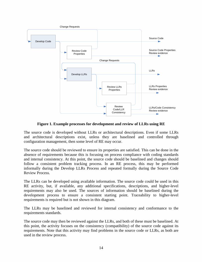
Figure 1. Example processes for development and review of LLRs using RE
The source code is developed without LLRs or architectural descriptions. Even if some LLRs and architectural descriptions exist, unless they are baselined and controlled through configuration management, then some level of RE may occur.
The source code should be reviewed to ensure its properties are satisfied. This can be done in the absence of requirements because this is focusing on process compliance with coding standards and internal consistency. At this point, the source code should be baselined and changes should follow a consistent problem tracking process. In an RE process, this may be performed informally during the Develop LLRs Process and repeated formally during the Source Code Review Process.
The LLRs can be developed using available information. The source code could be used in this RE activity, but, if available, any additional specifications, descriptions, and higher-level requirements may also be used. The sources of information should be baselined during the development process to ensure a consistent starting point. Traceability to higher-level requirements is required but is not shown in this diagram.
The LLRs may be baselined and reviewed for internal consistency and conformance to the requirements standards.
The source code may then be reviewed against the LLRs, and both of these must be baselined. At this point, the activity focuses on the consistency (compatibility) of the source code against its requirements. Note that this activity may find problems in the source code or LLRs, as both are used in the review process.
Develop Code
Develop LLRs
Review CodeProperties
Review LLRsProperties
Review Code/LLR
Consistency
Source Code
Source Code Properties Review evidence
LLRs Properties Review evidence
LLRs
LLRs/Code Consistency Review evidence
Change Requests
Change Requests
14
3.4.2 Generic RE Processes
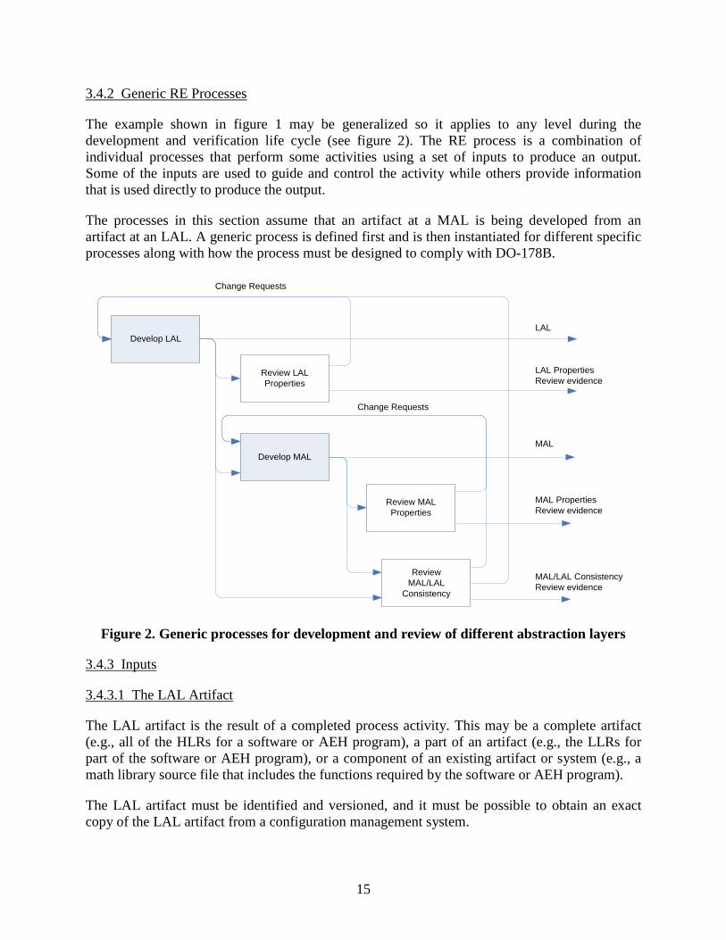
The example shown in figure 1 may be generalized so it applies to any level during the development and verification life cycle (see figure 2). The RE process is a combination of individual processes that perform some activities using a set of inputs to produce an output. Some of the inputs are used to guide and control the activity while others provide information that is used directly to produce the output.
The processes in this section assume that an artifact at a MAL is being developed from an artifact at an LAL. A generic process is defined first and is then instantiated for different specific processes along with how the process must be designed to comply with DO-178B.
Develop LAL
Develop MAL
Review LALProperties
Review MALProperties
Review MAL/LAL
Consistency
LAL
LAL Properties Review evidence
MAL Properties Review evidence
MAL
MAL/LAL Consistency Review evidence
Change Requests
Change Requests
Figure 2. Generic processes for development and review of different abstraction layers
3.4.3 Inputs
3.4.3.1 The LAL Artifact
The LAL artifact is the result of a completed process activity. This may be a complete artifact (e.g., all of the HLRs for a software or AEH program), a part of an artifact (e.g., the LLRs for part of the software or AEH program), or a component of an existing artifact or system (e.g., a math library source file that includes the functions required by the software or AEH program).
The LAL artifact must be identified and versioned, and it must be possible to obtain an exact copy of the LAL artifact from a configuration management system.
15
3.4.3.2 Project-Specific RE Development Process
The process activities to be performed must be described. This description could be part of the standard processes if they describe RE, or they could be specific procedures, addendums, work orders, etc., which make appropriate adjustments for RE.
3.4.3.3 The RE Standards Applicable to the Development Process
In a forward engineering process plan, the standards for requirements, design, and the source code development should exist before any of the requirements, design and source code are written. In an RE process, the code may exist before a formal coding standard is written.
In an RE process, a coding standard should be developed before any development of the requirements is started. This coding standard development will provide a level of assurance so that, although the original developer did not produce the code in accordance with a coding standard, the engineer developing the traceability between requirements and source code will provide this first-level check.
The standards should be no different whether a forward engineering or RE process is used, but it is important that they be available and used in accordance with the development and verification processes.
3.4.4 Outputs
3.4.4.1 MAL Product
This may be a complete or partial product, depending on the specific defined RE life cycle process. For example, if a program uses information managed as a linked list, then a set of functions may be provided in a library that groups these functions together. Such a library may have LLRs developed before the rest of the software. This would be a partial artifact and, if the requirements can be identified, versioned and baselined, they can be developed ahead of the rest of the program. The final MAL product would be a collection of the partial artifacts. This collection would be identified with a baseline identifier so that it could be carried forward to the certification package and identified in a software or AEH configuration index.
An alternative iterative life cycle may eventually produce artifacts that contain all of the LLRs required, but the artifacts could be partially completed containing sections for the requirements that have been developed at any particular iteration. The artifacts must be correctly versioned and controlled so that only authorized changes are incorporated in subsequent revisions. The final artifacts would be identified and carried forward to the certification package and identified in the software AEH configuration index.
The MAL product need not be a specific artifact while in partial state. The information could be held in a requirements repository or database, or organized in tables or in sets of related hypertext files. It is key that the artifacts are clearly identified and can be retrieved for inspection. There may be several levels of MALs, which link the levels of abstraction. At the highest level (the most abstract ), the MAL would be represented by HLRs, which are traced to
16
system requirements. These should be written in such a way that an SME can understand the HLRs and can confirm the traceability between system requirements and HLRs.
3.4.5 Entry Criteria
3.4.5.1 Status of the Inputs
This would be a specification of the configuration management criteria for the LAL product whose information would be used by the RE process.
3.4.5.2 Status of the Process
This would be a specification about the process description’s status for the development process being started. For example, this could require that the plans and standards for the process be approved and released and the PSAC be approved or planning review completed.
3.4.5.3 Status of the Standards
Other inputs that may affect the development of the MAL or play a role in detecting errors would be the standards. These should be under configuration control.
For example, in the case of developing LLRs from source code for a math library, the transition criteria for starting the development of the LLRs would require that the source code be under configuration control and verified to comply with a set of minimal coding standards.
3.4.6 Exit Criteria
3.4.6.1 Status of the Output
The output status is a specification of the configuration management and the development criteria needed on output artifacts to complete the development process.
Different exit criteria may be defined for partial completion and for total completion of the RE process. If only complete baselines are used, then all of the code could be reviewed against the coding standard, the development of all of the LLRs for that code, and the development of HLRs for those LLRs, respectively. This requires careful configuration control as well as problem report (PR) tracking because a revision to a version of the output will contain changes for many change requests. An iteration of the MAL product could contain many updates.
The MAL partial product could be hierarchical to reflect the software or requirements hierarchy. In the case of developing LLRs from source code for a math library, for example, the partial artifact could be the LLRs for a single math function. Another partial artifact could be the LLRs for a different math function from the same math library.
It could be that an LLR is reviewed and the LLR and its source code are under configuration control. This might require that all source code be traced to the LLR and that all LLRs have completed a design review to include the SME.
17
3.4.6.2 Completion Criteria
The completion criteria of the artifact depend on how the artifact is organized and managed.
If the artifact is a single entity, such as a complete LLR document, then the completion criteria must include the change history of all changes made to the document and show how each change was dispositioned.
If the artifact is organized hierarchically, then the completion criteria must also be organized hierarchically. If all of the functions in the math library have had LLRs developed, then the LLR representing the math library itself can be completed, as it is at that point that its completion can be confirmed.
The completion criterion for a partial artifact is a statement of the form “ready for review.”
3.4.7 Process Description
The process description describes the complete set of process steps that would transform the inputs to the outputs, including any process path selections due to the entry and exit criteria. This also discusses any actions for exceptions. For example, the process may state that the developer must establish all of the LLRs for any “.c” file for a math library that meets the entry criteria.
The process description should reference the applicable standards to be used or project-specific procedures that may refine the activities. For example, during the development of some LLRs from source code using an RE process, the engineer may find sequences of conditions that use arithmetic operators instead of logical operators. This may violate the coding standards because arithmetic operators combining conditions do not prescribe an evaluation order. Short circuit logical operators are typically preferred. The coding standard violation should be raised as a PR during the development process and should not wait until the subsequent code review process, which cannot start until the LLRs are baselined.
During the RE process, the engineer should find and record problems in the LAL product if they cannot develop a complete MAL product. For example, if a function in the source code has a parameter that points to a value to be used, then a requirement may be inserted for a robustness check to ensure the pointer has been initialized before use. If the source code does not have a null pointer check prior to dereferencing the parameter, then this should be raised as a PR and not left to the source code reviewer to address.
3.5 THE RE ASPECTS OF SOFTWARE VERIFICATION
The verification process for the delivered system must have some means of establishing total correctness (i.e., consistency with the requirements). Since software must execute in the system context, the system behavior must be assured to be correct, and this is where traditional forward engineering processes differ from RE processes.
In forward engineering, each individual development process uses an assumed correct artifact as input. The process can introduce some errors, which must be discovered by the verification process. These errors can be detected by analysis, reviews, or tests based on the correctness of
18
the input to a previous process. In the case where source code is developed from LLRs, it can be assumed that the LLRs are correct and any discrepancies between the LLRs and the source code will result in changes to the source code. The common theme of all these evaluations is the assumption on the correctness of the inputs.
In RE, we may know little or nothing about the correctness of the input to the process. For example, having only the source code for math libraries, it is unknown if the source code properly implements the math libraries or, in some cases, which math functions are implemented. As MAL is developed from LAL (e.g., LLRs from source code), it can only be assured that the MAL is a faithful representation of the LAL, but not whether all the required functions are present (completeness), desired, or correct. At some point, the correctness of the final MAL (e.g., system requirements or HLRs) must be established.
All the software requirements are verified by reviews and analysis in accordance with the DO-178B objectives. Any new derived requirements or changes to existing derived requirements should be provided to the system processes, including the system safety assessment process. If any system requirements were found to be inadequate or incorrect, the RE process should capture the issues and refer them to the system processes for resolution. The SME should be involved in the certification liason with the system processes.
The SME role in relation to RE is critical. The SME may be aided by a specification for a similar system, a set of desired system specifications refined from some knowledge of the end system, or a combination of the two. The RE process must establish the correctness of the last MAL artifact in the development chain.
The verification process, in general, would be the same for any specific development process regardless of the processes’ sequence. The goal would be to evaluate an artifact produced by a development process. This evaluation would include a comparison of the developed product (e.g., LLR) against the artifact from which it was developed (e.g., source code) for the DO-178B criteria of traceability and compliance. The two-way traceability would ensure that the artifacts are a faithful representation of each other. Additionally, the DO-178B process provides assurance that specific desirable properties exist in the developed artifact. These verification goals are independent of the order of development. For example, the verification process for a specific development process is not sensitive to whether the source code was developed from the LLR or the LLR was developed from the source code. The description of the development objectives in DO-178B Section 5 tends to be dependent on the direction of development. For example, Table A-2 objective 4 states, “Low-level requirements are developed,” but DO-178B Section 5.2.1a states “The software architecture and low-level requirements are developed from the high-level requirements.” This is inconsistent with the statement in DO-178B Section 12.1.4d, which states, “Reverse engineering may be used to regenerate software life cycle data that is inadequate or missing in satisfying the objectives of this document.” The verification objectives in DO-178B Section 6 tend to be independent of the direction of development. For example, table A-4, objective 1, reads “Low-level requirements comply with high-level requirements,” and DO-178B Section 6.3.2a states, “The objective is to ensure that the software low-level requirements satisfy the software high-level requirements and that derived requirements and the design basis for their existence are correctly defined.”
19
Another aspect of the RE process is the behavioral discovery process. In some cases the RE process might discover a behavior that is desirable at the end system level but the SME role did not include this behavior in their system view.
This may occur during a forward engineering process or an RE process. In a forward engineering process the insertion of additional behavior is normally limited to additions of robustness checks, which catch errors discovered through possible consistency violations (e.g., range checks before indexing). Other insertions are less likely because the developer is producing the LAL under the assumption that the input as presented in the MAL is correct.
The RE processes proposed include propagating information from the LAL to the MAL and raising PRs if necessary. The RE process may develop derived LLRs, which would be propagated to the SME who would interact with the System Development and Safety Assessment processes.
Another source of problems may be lack of functionality in the LAL, or the SME may identify required functionality at the system level that was not contained in the original LAL used to initiate the RE process. Conversely, the LAL may contain functionality not needed at the MAL or system level for a specific installation, potentially resulting in extraneous or dead code at the system or product function level.
Process models proposed for an RE approach should incorporate an SME to be a part of the verification process.
3.6 GENERIC RE SME VERIFICATION PROCESS
3.6.1 Inputs
The inputs to the SME verification process include the highest level of software requirements, which should be traced to a set of system requirements. The SME must be familiar with the intended behavior of the system to ensure that it matches the intended behavior of the software.
3.6.1.1 The MAL Artifact
The MAL artifact may be a complete or partial artifact. An example would be a situation in which all of the reverse engineered HLRs are available for an aircraft power control system, or only a specific subset of HLRs for the power distribution system associated with the engine-start function are available. It is also possible that portions of the reverse engineered HLRs are available, as would be the case in an iterative development process.
3.6.1.2 The SME Knowledge Base
The SME knowledge base is the collection of data used to verify and validate the correctness and completeness of the MAL artifact, and this could be a set of forward engineered system requirements (the mental model of a human expert), perhaps aided by specifications from a similar or previous system.
20
3.6.1.3 RE Standards Applicable to the SME Verification Process
The standards used by SMEs would be the same as those used by software developers and verification engineers. As the SMEs also work at the system boundary, they may be required to use additional System Development and Safety Assessment standards.
3.6.2 Outputs
3.6.2.1 Verification Records
Verification records may be a complete or partial artifact, depending on the specific defined RE life cycle. For example, an iterative life cycle may produce multiple versions of HLRs to be verified as more functionality is added from the RE process.
3.6.2.2 The PRs
PRs identify the discrepancies between the SME knowledge base and the MAL artifact. Although some PRs may be genuine problems, others may be issues raised by the developers due to incomplete information or to confirm specific assumptions. For example, these could represent errors between the SME view of how a tangent function should respond and the HLR for the tangent function. Responses to denormalized floating-point numbers could be underspecified, and the treatment for Signaling NaN (not a number) could have been specified while a Quiet NaN could have been missed. The HLR developer could have raised an issue using a PR that addresses the relative precision of the tangent function as its return value approaches the asymptote.
Even though the PRs are resolved, they form a record of the discussion between the SME and the development and verification teams.
It is important to identify the SME in the PR process.
3.6.3 Entry Criteria
3.6.3.1 Status of the Inputs
Input status is a specification of the configuration management and verification criterion needed on an input artifact or information before the specific SME verification process would start. For example, in the case of HLRs for a math library, the transition criteria for starting the SME verification activity could be a requirement that the HLR be under configuration control and all verification tasks for the HLRs be completed with no open PRs. An additional requirement could be to document the system requirements for the math library and put it under change control.
3.6.3.2 Status of the Process
This would be a specification about the status of the process description before the SME verification process is started. For example, this could require that the plans and standards for the SME verification process be released and the PSAC approved or planning review completed.
21
3.6.4 Exit Criteria
3.6.4.1 Status of the Output
The output status is a completion specification of the SME verification results.
Different exit criteria may be defined for partial and total completion of each process activity. For example, there may be a requirement that each HLR can be traced to a review record.
3.6.5 Process Description
The process description describes the complete set of process activities that would transform the inputs to the outputs, including any process path selections due to entry and exit criteria. This would also discuss any actions for exceptions. For example, the process may state that the system engineer completes the system requirement or HLR checklist for each system function. If there are any functions discovered in the HLRs that should be added to the system requirements, a system level PR should be generated.
3.7 ACCEPTANCE CRITERIA
In a forward engineering process, developers are expected to understand the MAL before they can develop the LAL artifacts. A source code developer will need to understand the LLRs before developing the code; otherwise, the code will not comply with the LLRs. In an RE process, the LLRs may be developed from source code without due regard to the difference in the abstraction level and the resulting LLRs being too similar to the code (e.g., pseudocode). Because such translations may be performed with little intellectual effort or understanding of the code’s intent, these practices should not be permitted on RE projects because they do not provide the same level of confidence as a forward engineering process.
The difference between abstraction levels should demonstrate some level of understanding, either by differences in the representations or the provision of additional information, such as context information or rationale between HLR and LLR mapping.
The other acceptance criteria follow on from those required for DO-178B and DO-254 [1].
22
4. VALIDATION OF FRAMEWORK
The framework was validated by examining two projects that had already been accepted by the FAA and assessing how closely these projects matched the proposed framework. One software project and one AEH project were chosen. The two projects were:
1. GNAT Ada Run-Time Environment (ARTE), a project using the GNU (“GNU’s Not Unix!”) unix-like computer operating system and the New York University Ada 9X Translator (compiler). This project was chosen because it is open source software licensed under the GPL and can be distributed freely.
2. An AEH project involving two programmable logic devices.
The use of RE on both projects was found to be consistent with the framework described in this report; it is understood that if an RE project adopts the framework suggested in this research, it will most likely be acceptable to the FAA. The detailed assessment of these projects can be found in appendices D and E.
5. RECOMMENDATIONS
The recommendations resulting from this research are:
1. If RE is used on a project, then it is important that the process plans and standards clearly describe the information flow during the development of the system, software, or AEH components. While this is expected from a well-written set of plans and standards, the information flow may be assumed and not documented clearly. The transition criteria, configuration management (especially when data are placed under configuration control), problem reporting, change control, and status accounting may differ from the corresponding activities on a forward engineering project.
2. The PSAC or Plan for Hardware Aspects of Certification (PHAC) should be open and direct in describing the proposed RE processes. Failure to explain how RE is to be used on the project is likely to lead to rejection of the PSAC or PHAC or cause problems when the extent of RE is uncovered during the SOI audits.
3. The QA records should describe in-process audits conducted to ensure that process plans and standards are being followed. While this is not specific to RE, it may be more difficult to track the information flow, which requires additional attention.
4. The use of SMEs is critical to any RE project. Their use should be identified in the PSAC and PHAC and required as part of the guidance. Depending on the extent of RE on a particular project, SMEs are likely to be required to cover the following topics:
a. Domain and system knowledge, and certification liaison with system processes
b. Software architecture and source code
23
5. Careful consideration should be given to the difference between abstraction levels to ensure that there is sufficient intellectual value added to demonstrate a thorough understanding of the two representations being traced and verified. The difference between the abstraction levels should indicate sound engineering judgment for a higher-level representation that could be transformed to an equivalent lower-level representation. For example:
a. If the LLRs are a simple restatement of the code (e.g., pseudocode that is very close to the code), then tests based on such LLRs will exercise only the implementation and not the expected behavior and functionality. The capacity of low-level testing to detect incorrect functionality, missing functionality, and unintended functions will be severely compromised. The design decisions representing the difference between LLRs and code are nonexistent or unsound.
b. If the gap between the HLRs and LLRs is too great, it will be difficult to verify that the HLRs were developed correctly into LLRs, and derived requirements may be missed. The design decisions between HLRs and LLRs are too big, and it would be too difficult to develop HLRs into equivalent LLRs using sound design decisions.
6. It is particularly important that the LAL should be placed under configuration management before commencing the development of the MAL. It can be difficult to determine whether RE is being used if the artifacts are not under proper configuration management.
7. When reviewing each reverse-engineered artifact, the following issues should be considered:
a. Is there more functionality in the LAL than required by the MAL — are the LAL elements necessary?
b. Is there less functionality in the LAL than required by the MAL — are the LAL elements sufficient?
c. Are there any errors in the LAL-MAL translation — is the translation between the LAL and the MAL correct?
8. It should be a policy that when RE is performed, all robustness checks should be called out as LLRs. This policy would ensure that robustness checks are considered in the testing process, the source to LLR reviews, and propagated up in line with DO-178B [7] objectives.
9. The Software Requirements Standards and Software Design Standards should define how and when RE techniques are to be used.
10. The process plans should describe and formalize the use of SMEs.
24
11. The review checklists should ensure that the LLRs show some level of understanding of the source code’s intent and are not too close a match to the source code.
While the report is written using DO-178B [7] as the primary reference, the recommendations also apply to AEH components reverse engineered to comply with DO-254 [9].
6. CONCLUSIONS
The survey found that the majority of respondents have already used reverse engineering (RE); however, the literature survey found very little published research on the application of RE techniques to safety-critical software. The majority of the reported projects using RE were accepted by the FAA, although usually with changes requested to the Plan for Software Aspects of Certification (PSAC) or Plan for Hardware Aspects of Certification (PHAC). Although DO-178B contains an explicit reference to RE, the majority of the guidance is written from a forward engineering perspective. Therefore, additional guidance for RE is needed to incorporate the recommendations made in Section 5 of this report. The development of this additional guidance is out of this report’s scope. The references in this report relate to DO-178B. While the belief is that this report should be applicable to DO-178C based on the state of the document when this report was written, an evaluation of the impact of DO-178C on this report will need to be done. The framework was validated by assessing two RE projects, already accepted by the FAA. One software project and one airborne electronic hardware (AEH) project were chosen. The RE activities performed on the two projects were found to be compatible with the framework described in this report. The software project is described in appendix D, while the AEH project is described in appendix E. The survey showed the importance of projects being open and honest in their use of RE. The RE aspects need to be addressed during the planning phase; otherwise the PSAC and PHAC may be rejected. The certification authorities need to agree with the use of RE; otherwise the software may fail to gain approval when the extent of RE is revealed during the stage-of-involvement audits. The case studies confirmed the importance of involving subject matter experts (SMEs) in the RE process. SMEs provide the expert knowledge of the domain, required system behavior, software architecture, and source code that might otherwise be missing in an RE environment. It is unlikely that a single individual will have all the required expertise, so an RE project is likely to need a team of SMEs.
7. REFERENCES
1. Guidance for Parts Manufacturer Approval of Turbine Engine and Auxiliary Power Unit Parts Under Test and Computation, ANE-110, September 8, 2009.
2. FAA Order 8110.42C, Parts Manufacturer Approval Procedures, AIR-110, June 23, 2008.
25
3. Agile Manifesto, http://agilemanifesto.org/iso/en/, accessed June 30, 2015
4. Evolutionary Rapid Development,” SPC document SPC-97057-CMC, version 1.00.04, June 1997.
5. GNU General Public License, http://www.gnu.org/licenses/gpl-3.0.txt, accessed June 20, 2015.
6. Peter H. Feiler, “Reengineering: An Engineering Problem,” Special Report CMU/SEI-93-SR-5, 1993.
7. RTCA/DO-178B, “Software Considerations in Airborne Systems and Equipment Certification,” December 1, 1992.
8. Certification Authorities Software Team (CAST) Position Paper 18, “Reverse Engineering in Certification Projects” June 2003. http://www.faa.gov/aircraft/air_cert/design_approvals/ air_software/cast/cast_papers/media/cast-18.pdf
9. RTCA/DO-254, “Design Assurance Guidance for Airborne Electronic Hardware,” April 19, 2000.
10. Royce W.W., “Managing the development of large software systems,” Institute of Electrical and Electronics Engineers, Proceedings, IEEE WESCON, August 1970, pp. 1–9.
26
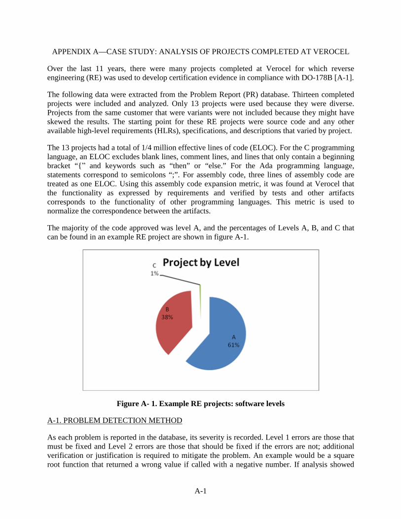
APPENDIX A—CASE STUDY: ANALYSIS OF PROJECTS COMPLETED AT VEROCEL
Over the last 11 years, there were many projects completed at Verocel for which reverse engineering (RE) was used to develop certification evidence in compliance with DO-178B [A-1].
The following data were extracted from the Problem Report (PR) database. Thirteen completed projects were included and analyzed. Only 13 projects were used because they were diverse. Projects from the same customer that were variants were not included because they might have skewed the results. The starting point for these RE projects were source code and any other available high-level requirements (HLRs), specifications, and descriptions that varied by project.
The 13 projects had a total of 1/4 million effective lines of code (ELOC). For the C programming language, an ELOC excludes blank lines, comment lines, and lines that only contain a beginning bracket “{ˮ and keywords such as “then” or “else.” For the Ada programming language, statements correspond to semicolons “;”. For assembly code, three lines of assembly code are treated as one ELOC. Using this assembly code expansion metric, it was found at Verocel that the functionality as expressed by requirements and verified by tests and other artifacts corresponds to the functionality of other programming languages. This metric is used to normalize the correspondence between the artifacts.
The majority of the code approved was level A, and the percentages of Levels A, B, and C that can be found in an example RE project are shown in figure A-1.
Figure A- 1. Example RE projects: software levels
A-1. PROBLEM DETECTION METHOD
As each problem is reported in the database, its severity is recorded. Level 1 errors are those that must be fixed and Level 2 errors are those that should be fixed if the errors are not; additional verification or justification is required to mitigate the problem. An example would be a square root function that returned a wrong value if called with a negative number. If analysis showed
Series1, A,
154154, 61%
Series1, B,
95672, 38%
Series1, C, 1500, 1%
Project by Level
A-1
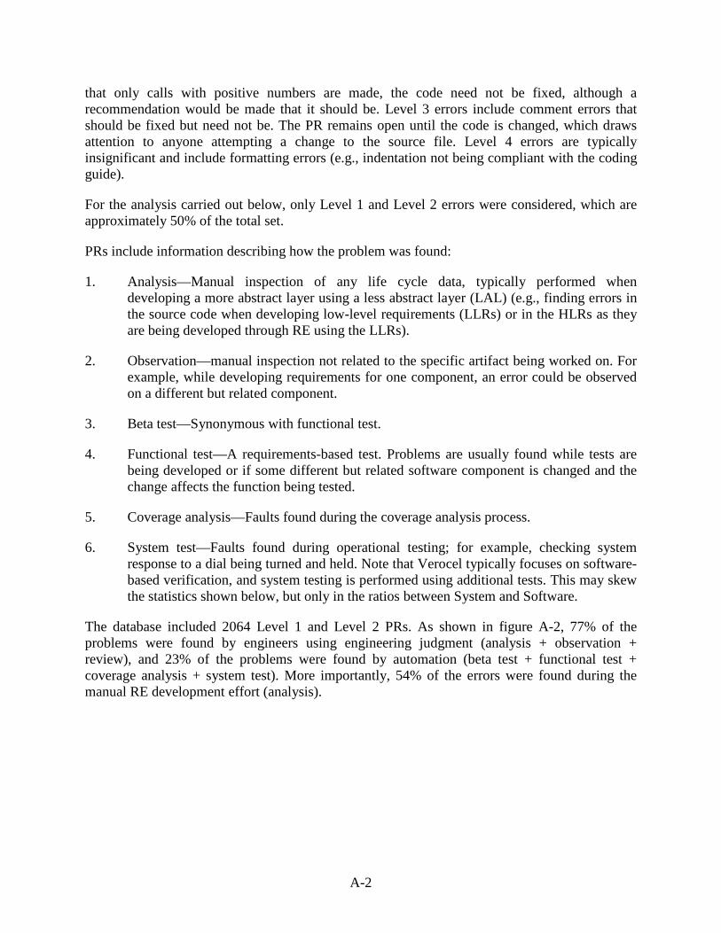
that only calls with positive numbers are made, the code need not be fixed, although a recommendation would be made that it should be. Level 3 errors include comment errors that should be fixed but need not be. The PR remains open until the code is changed, which draws attention to anyone attempting a change to the source file. Level 4 errors are typically insignificant and include formatting errors (e.g., indentation not being compliant with the coding guide).
For the analysis carried out below, only Level 1 and Level 2 errors were considered, which are approximately 50% of the total set.
PRs include information describing how the problem was found:
1. Analysis—Manual inspection of any life cycle data, typically performed when developing a more abstract layer using a less abstract layer (LAL) (e.g., finding errors in the source code when developing low-level requirements (LLRs) or in the HLRs as they are being developed through RE using the LLRs).
2. Observation—manual inspection not related to the specific artifact being worked on. For example, while developing requirements for one component, an error could be observed on a different but related component.
3. Beta test—Synonymous with functional test.
4. Functional test—A requirements-based test. Problems are usually found while tests are being developed or if some different but related software component is changed and the change affects the function being tested.
5. Coverage analysis—Faults found during the coverage analysis process.
6. System test—Faults found during operational testing; for example, checking system response to a dial being turned and held. Note that Verocel typically focuses on software-based verification, and system testing is performed using additional tests. This may skew the statistics shown below, but only in the ratios between System and Software.
The database included 2064 Level 1 and Level 2 PRs. As shown in figure A-2, 77% of the problems were found by engineers using engineering judgment (analysis + observation + review), and 23% of the problems were found by automation (beta test + functional test + coverage analysis + system test). More importantly, 54% of the errors were found during the manual RE development effort (analysis).
A-2
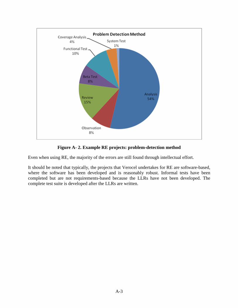
Figure A- 2. Example RE projects: problem-detection method
Even when using RE, the majority of the errors are still found through intellectual effort.
It should be noted that typically, the projects that Verocel undertakes for RE are software-based, where the software has been developed and is reasonably robust. Informal tests have been completed but are not requirements-based because the LLRs have not been developed. The complete test suite is developed after the LLRs are written.
Series1, Analysis, 1108, 54%
Series1, Observation, 168,
8%
Series1, Review, 315, 15%
Series1, Beta Test, 159, 8%
Series1, Functional Test, 205, 10%
Series1, Coverage Analysis, 87, 4%
Series1, System Test, 22, 1%
Problem Detection Method
A-3
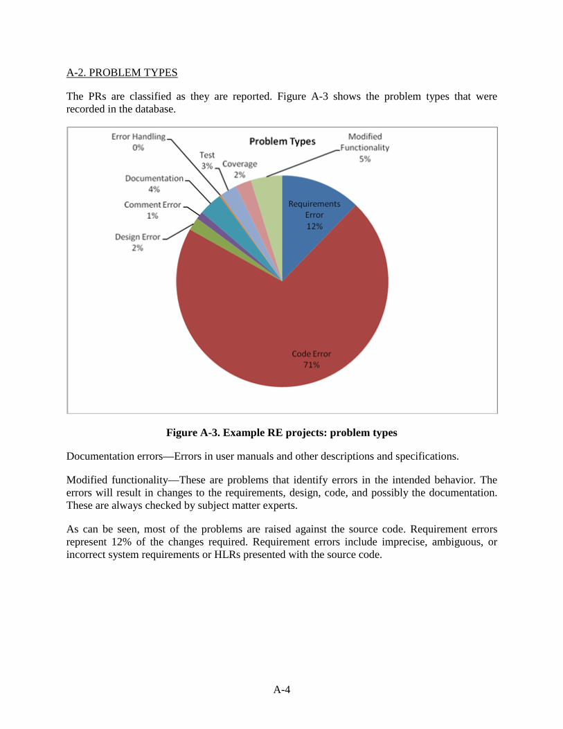
A-2. PROBLEM TYPES
The PRs are classified as they are reported. Figure A-3 shows the problem types that were recorded in the database.
Figure A-3. Example RE projects: problem types
Documentation errors—Errors in user manuals and other descriptions and specifications.
Modified functionality—These are problems that identify errors in the intended behavior. The errors will result in changes to the requirements, design, code, and possibly the documentation. These are always checked by subject matter experts.
As can be seen, most of the problems are raised against the source code. Requirement errors represent 12% of the changes required. Requirement errors include imprecise, ambiguous, or incorrect system requirements or HLRs presented with the source code.
Series1, Requirements
Error, 252, 12%
Series1, Code Error, 1464, 71%
Series1, Design Error, 41, 2% Series1,
Comment Error, 24, 1%
Series1, Documentation,
75, 4%
Series1, Error Handling, 5, 0%
Series1, Test, 54, 3%
Series1, Coverage, 50, 2%
Series1, Modified Functionality, 99, 5%
Problem Types
A-4
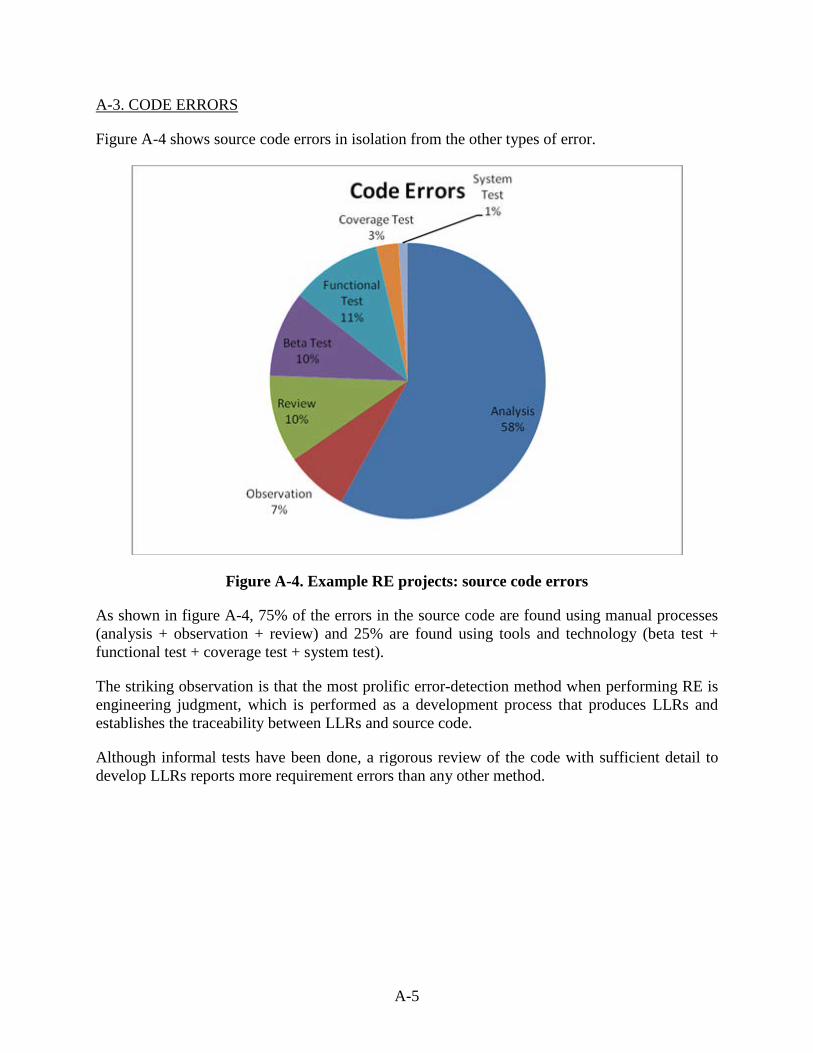
A-3. CODE ERRORS
Figure A-4 shows source code errors in isolation from the other types of error.
Figure A-4. Example RE projects: source code errors
As shown in figure A-4, 75% of the errors in the source code are found using manual processes (analysis + observation + review) and 25% are found using tools and technology (beta test + functional test + coverage test + system test).
The striking observation is that the most prolific error-detection method when performing RE is engineering judgment, which is performed as a development process that produces LLRs and establishes the traceability between LLRs and source code.
Although informal tests have been done, a rigorous review of the code with sufficient detail to develop LLRs reports more requirement errors than any other method.
Series1, Analysis, 849, 58%
Series1, Observation, 108,
7%
Series1, Review, 150, 10%
Series1, Beta Test, 147, 10%
Series1, Functional Test, 156,
11%
Series1, Coverage Test, 38, 3%
Series1, System Test, 16, 1%
Code Errors
A-5
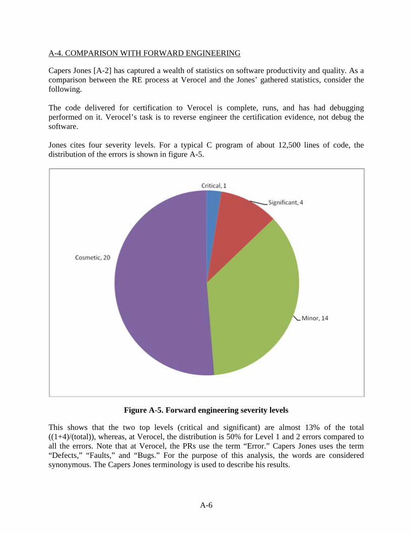
A-4. COMPARISON WITH FORWARD ENGINEERING
Capers Jones [A-2] has captured a wealth of statistics on software productivity and quality. As a comparison between the RE process at Verocel and the Jones’ gathered statistics, consider the following. The code delivered for certification to Verocel is complete, runs, and has had debugging performed on it. Verocel’s task is to reverse engineer the certification evidence, not debug the software. Jones cites four severity levels. For a typical C program of about 12,500 lines of code, the distribution of the errors is shown in figure A-5.
Figure A-5. Forward engineering severity levels
This shows that the two top levels (critical and significant) are almost 13% of the total ((1+4)/(total)), whereas, at Verocel, the distribution is 50% for Level 1 and 2 errors compared to all the errors. Note that at Verocel, the PRs use the term “Error.” Capers Jones uses the term “Defects,” “Faults,” and “Bugs.” For the purpose of this analysis, the words are considered synonymous. The Capers Jones terminology is used to describe his results.
Series1, Critical, 1, 3% Series1, Significant,
4, 10%
Series1, Minor, 14, 36%
Series1, Cosmetic, 20, 51%
A-6
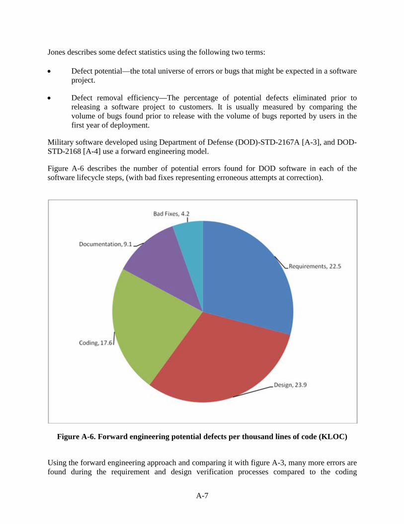
Jones describes some defect statistics using the following two terms: • Defect potential—the total universe of errors or bugs that might be expected in a software
project.
• Defect removal efficiency—The percentage of potential defects eliminated prior to releasing a software project to customers. It is usually measured by comparing the volume of bugs found prior to release with the volume of bugs reported by users in the first year of deployment.
Military software developed using Department of Defense (DOD)-STD-2167A [A-3], and DOD-STD-2168 [A-4] use a forward engineering model.
Figure A-6 describes the number of potential errors found for DOD software in each of the software lifecycle steps, (with bad fixes representing erroneous attempts at correction).
Figure A-6. Forward engineering potential defects per thousand lines of code (KLOC)
Using the forward engineering approach and comparing it with figure A-3, many more errors are found during the requirement and design verification processes compared to the coding
Series1, Requirements, 22.5,
29%
Series1, Design, 23.9, 31%
Series1, Coding, 17.6, 23%
Series1, Documentation, 9.1,
12%
Series1, Bad Fixes, 4.2, 5%
A-7
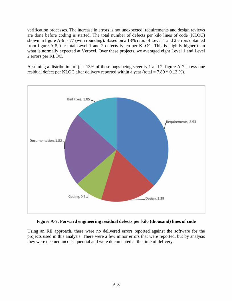
verification processes. The increase in errors is not unexpected; requirements and design reviews are done before coding is started. The total number of defects per kilo lines of code (KLOC) shown in figure A-6 is 77 (with rounding). Based on a 13% ratio of Level 1 and 2 errors obtained from figure A-5, the total Level 1 and 2 defects is ten per KLOC. This is slightly higher than what is normally expected at Verocel. Over these projects, we averaged eight Level 1 and Level 2 errors per KLOC. Assuming a distribution of just 13% of these bugs being severity 1 and 2, figure A-7 shows one residual defect per KLOC after delivery reported within a year (total = 7.89 * 0.13 %).
Figure A-7. Forward engineering residual defects per kilo (thousand) lines of code
Using an RE approach, there were no delivered errors reported against the software for the projects used in this analysis. There were a few minor errors that were reported, but by analysis they were deemed inconsequential and were documented at the time of delivery.
Series1, Requirements, 2.93,
37%
Series1, Design, 1.39, 18%
Series1, Coding, 0.7, 9%
Series1, Documentation,
1.82, 23%
Series1, Bad Fixes, 1.05, 13%
A-8
REFERENCES
A-1 RTCA/DO-178B, “Software Considerations in Airborne Systems and Equipment Certification,” December 1, 1992.
A-2. Capers Jones, Software Quality, “Analysis and Guidelines for Success,” 1997.
A-3. DOD-STD-2167, Military Standard, Defense System Software Development, June 4, 1985.
A-4. DOD-STD-2168, Military Standard, Defense System Software Quality Program,
April 29, 1988.
A-9
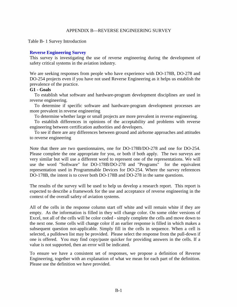
APPENDIX B—REVERSE ENGINEERING SURVEY Table B- 1 Survey Introduction Reverse Engineering Survey This survey is investigating the use of reverse engineering during the development of safety critical systems in the aviation industry. We are seeking responses from people who have experience with DO-178B, DO-278 and DO-254 projects even if you have not used Reverse Engineering as it helps us establish the prevalence of the practice. G1 - Goals
To establish what software and hardware-program development disciplines are used in reverse engineering.
To determine if specific software and hardware-program development processes are more prevalent in reverse engineering
To determine whether large or small projects are more prevalent in reverse engineering. To establish differences in opinions of the acceptability and problems with reverse
engineering between certification authorities and developers. To see if there are any differences between ground and airborne approaches and attitudes
to reverse engineering
Note that there are two questionnaires, one for DO-178B/DO-278 and one for DO-254. Please complete the one appropriate for you, or both if both apply. The two surveys are very similar but will use a different word to represent one of the representations. We will use the word "Software" for DO-178B/DO-278 and "Programs" for the equivalent representation used in Programmable Devices for DO-254. Where the survey references DO-178B, the intent is to cover both DO-178B and DO-278 in the same questions. The results of the survey will be used to help us develop a research report. This report is expected to describe a framework for the use and acceptance of reverse engineering in the context of the overall safety of aviation systems. All of the cells in the response column start off white and will remain white if they are empty. As the information is filled in they will change color. On some older versions of Excel, not all of the cells will be color coded - simply complete the cells and move down to the next one. Some cells will change color if an earlier response is filled in which makes a subsequent question not-applicable. Simply fill in the cells in sequence. When a cell is selected, a pulldown list may be provided. Please select the response from the pull-down if one is offered. You may find copy/paste quicker for providing answers in the cells. If a value is not supported, then an error will be indicated.
To ensure we have a consistent set of responses, we propose a definition of Reverse Engineering, together with an explanation of what we mean for each part of the definition. Please use the definition we have provided.
B-1
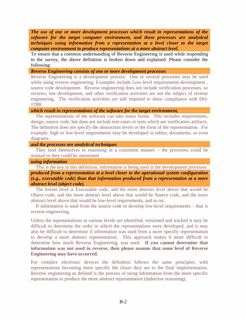
The use of one or more development processes which result in representations of the software for the target computer environment, and these processes are analytical techniques using information from a representation at a level closer to the target computer environment to produce representations at a more abstract level. To ensure that a common understanding of Reverse Engineering is used while responding to the survey, the above definition is broken down and explained. Please consider the following: Reverse Engineering consists of one or more development processes Reverse Engineering is a development process. One or several processes may be used while using reverse engineering. Examples include Low-level requirements development , source code development. Reverse engineering does not include verification processes, so reviews, test development, and other verification activities are not the subject of reverse engineering. The verification activities are still required to show compliance with DO-178B. which result in representations of the software for the target environment,
The representations of the software can take many forms. This includes requirements, design, source code, but does not include test-cases or tests which are verification artifacts. The definition does not specify the abstraction levels or the form of the representation. For example, high or low-level requirements may be developed in tables, documents, or even diagrams. and the processes are analytical techniques
They lend themselves to reasoning in a consistent manner – the processes could be manual or they could be automated using information
This is the key in this definition, information is being used in the development processes produced from a representation at a level closer to the operational system configuration (e.g., executable code) than that information produced from a representation at a more abstract level (object code).
The lowest level is Executable code, and the more abstract level above that would be Object code, and the more abstract level above that would be Source code, and the more abstract level above that would be low-level requirements, and so on.
If information is used from the source code to develop low-level requirements – that is reverse engineering.
Unless the representations at various levels are identified, versioned and tracked it may be difficult to determine the order in which the representations were developed, and it may also be difficult to determine if information was used from a more specific representation to develop a more abstract representation. This approach makes it more difficult to determine how much Reverse Engineering, was used. If you cannot determine that information was not used in reverse, then please assume that some level of Reverse Engineering may have occurred. For complex electronic devices the definition follows the same principles, with representations becoming more specific the closer they are to the final implementation. Reverse engineering as defined is the process of using information from the more specific representation to produce the more abstract representation (inductive reasoning).
B-2
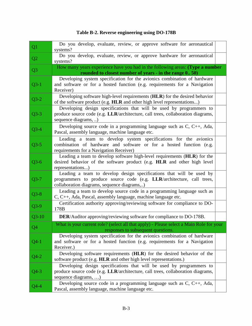
Table B-2. Reverse engineering using DO-178B
Q1 Do you develop, evaluate, review, or approve software for aeronautical systems?
Q2 Do you develop, evaluate, review, or approve hardware for aeronautical systems?
Q3 How many years experience have you had in the following areas: (Type a number rounded to closest number of years - in the range 0.. 50)
Q3-1 Developing system specification for the avionics combination of hardware
and software or for a hosted function (e.g. requirements for a Navigation Receiver)
Q3-2 Developing software high-level requirements (HLR) for the desired behavior of the software product (e.g. HLR and other high level representations...)
Q3-3 Developing design specifications that will be used by programmers to
produce source code (e.g. LLR/architecture, call trees, collaboration diagrams, sequence diagrams, ..)
Q3-4 Developing source code in a programming language such as C, C++, Ada, Pascal, assembly language, machine language etc.
Q3-5 Leading a team to develop system specifications for the avionics
combination of hardware and software or for a hosted function (e.g. requirements for a Navigation Receiver)
Q3-6 Leading a team to develop software high-level requirements (HLR) for the
desired behavior of the software product (e.g. HLR and other high level representations...)
Q3-7 Leading a team to develop design specifications that will be used by
programmers to produce source code (e.g. LLR/architecture, call trees, collaboration diagrams, sequence diagrams,..)
Q3-8 Leading a team to develop source code in a programming language such as C, C++, Ada, Pascal, assembly language, machine language etc.
Q3-9 Certification authority approving/reviewing software for compliance to DO-178B
Q3-10 DER/Auditor approving/reviewing software for compliance to DO-178B.
Q4 What is your current role? (select all that apply) - Please select a Main Role for your responses to subsequent questions.
Q4-1 Developing system specification for the avionics combination of hardware
and software or for a hosted function (e.g. requirements for a Navigation Receiver.)
Q4-2 Developing software requirements (HLR) for the desired behavior of the software product (e.g. HLR and other high level representations.)
Q4-3 Developing design specifications that will be used by programmers to
produce source code (e.g. LLR/architecture, call trees, collaboration diagrams, sequence diagrams, …)
Q4-4 Developing source code in a programming language such as C, C++, Ada, Pascal, assembly language, machine language etc.
B-3
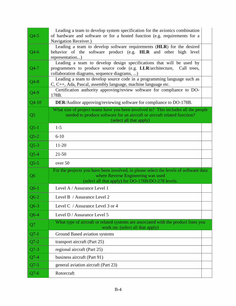
Q4-5 Leading a team to develop system specification for the avionics combination
of hardware and software or for a hosted function (e.g. requirements for a Navigation Receiver.)
Q4-6 Leading a team to develop software requirements (HLR) for the desired
behavior of the software product (e.g. HLR and other high level representation...)
Q4-7 Leading a team to develop design specifications that will be used by
programmers to produce source code (e.g. LLR/architecture, Call trees, collaboration diagrams, sequence diagrams, ...)
Q4-8 Leading a team to develop source code in a programming language such as C, C++, Ada, Pascal, assembly language, machine language etc.
Q4-9 Certification authority approving/review software for compliance to DO-178B.
Q4-10 DER/Auditor approving/reviewing software for compliance to DO-178B.
Q5 What size of project teams have you been involved in? This includes all the people
needed to produce software for an aircraft or aircraft related function? (select all that apply)
Q5-1 1-5
Q5-2 6-10
Q5-3 11-20
Q5-4 21-50
Q5-5 over 50
Q6 For the projects you have been involved, in please select the levels of software data
where Reverse Engineering was used (select all that apply) for DO-178B/DO-278 levels.
Q6-1 Level A / Assurance Level 1
Q6-2 Level B / Assurance Level 2
Q6-3 Level C / Assurance Level 3 or 4
Q6-4 Level D / Assurance Level 5
Q7 What type of aircraft or related systems are associated with the product lines you work on: (select all that apply)
Q7-1 Ground Based aviation systems
Q7-2 transport aircraft (Part 25)
Q7-3 regional aircraft (Part 25)
Q7-4 business aircraft (Part 91)
Q7-5 general aviation aircraft (Part 23)
Q7-6 Rotorcraft
B-4
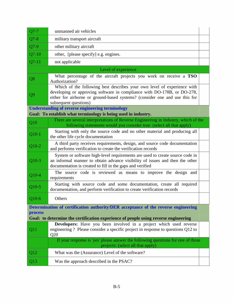
Q7-7 unmanned air vehicles
Q7-8 military transport aircraft
Q7-9 other military aircraft
Q7-10 other, [please specify] e.g. engines.
Q7-11 not applicable
Level of experience
Q8 What percentage of the aircraft projects you work on receive a TSO Authorization?
Q9
Which of the following best describes your own level of experience with developing or approving software in compliance with DO-178B, or DO-278, either for airborne or ground-based systems? (consider one and use this for subsequent questions)
Understanding of reverse engineering terminology Goal: To establish what terminology is being used in industry.
Q10 There are several interpretations of Reverse Engineering in Industry, which of the following statements would you consider true: (select all that apply)
Q10-1 Starting with only the source code and no other material and producing all the other life cycle documentation
Q10-2 A third party receives requirements, design, and source code documentation and performs verification to create the verification records
Q10-3 System or software high-level requirements are used to create source code in
an informal manner to obtain advance visibility of issues and then the other documentation is created to fill in the gaps and verified
Q10-4 The source code is reviewed as means to improve the design and requirements
Q10-5 Starting with source code and some documentation, create all required documentation, and perform verification to create verification records
Q10-6 Others
Determination of certification authority/DER acceptance of the reverse engineering process
Goal: to determine the certification experience of people using reverse engineering
Q11 Developers: Have you been involved in a project which used reverse
engineering ? Please consider a specific project in response to questions Q12 to Q20
If your response is 'yes' please answer the following questions for one of those projects: (select all that apply)
Q12 What was the (Assurance) Level of the software?
Q13 Was the approach described in the PSAC?
B-5
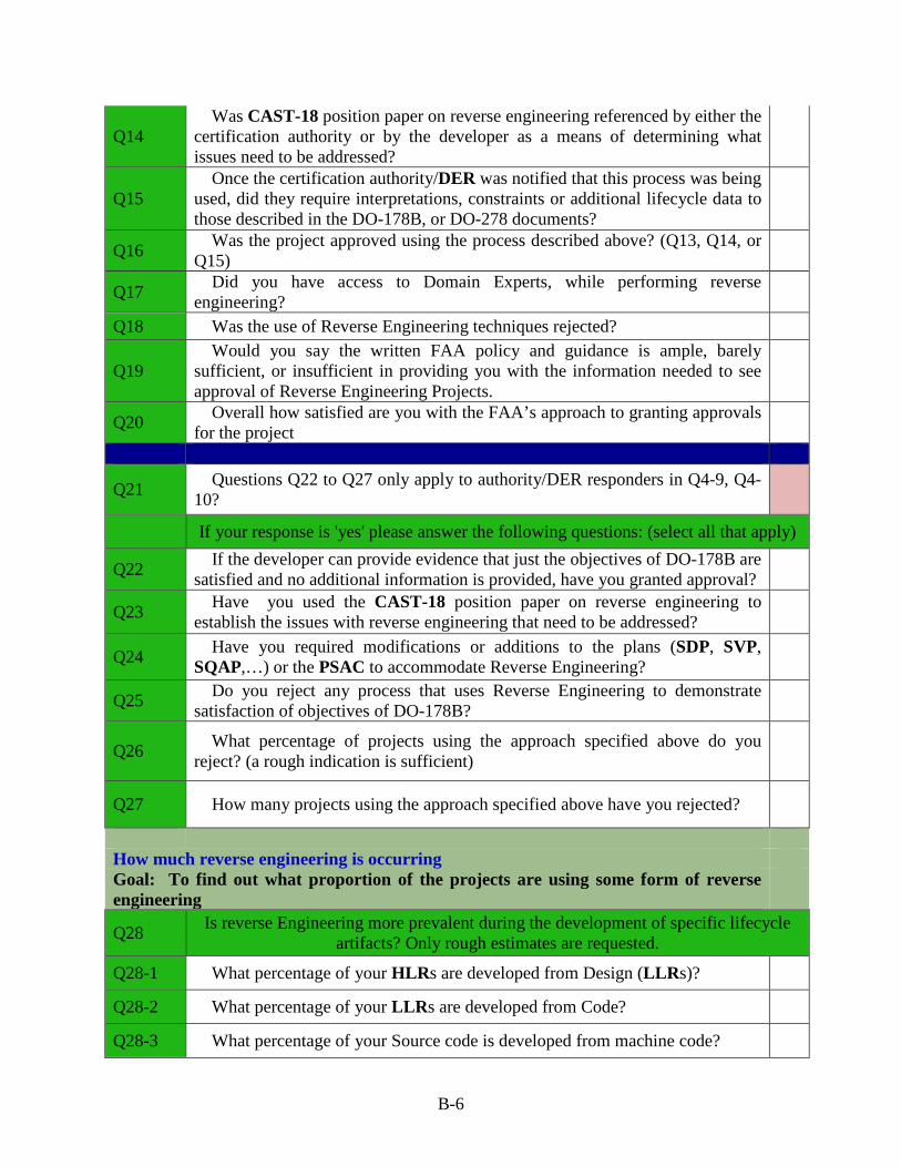
Q14 Was CAST-18 position paper on reverse engineering referenced by either the
certification authority or by the developer as a means of determining what issues need to be addressed?
Q15 Once the certification authority/DER was notified that this process was being
used, did they require interpretations, constraints or additional lifecycle data to those described in the DO-178B, or DO-278 documents?
Q16 Was the project approved using the process described above? (Q13, Q14, or Q15)
Q17 Did you have access to Domain Experts, while performing reverse engineering?
Q18 Was the use of Reverse Engineering techniques rejected?
Q19 Would you say the written FAA policy and guidance is ample, barely
sufficient, or insufficient in providing you with the information needed to see approval of Reverse Engineering Projects.
Q20 Overall how satisfied are you with the FAA’s approach to granting approvals for the project
Q21 Questions Q22 to Q27 only apply to authority/DER responders in Q4-9, Q4-10?
If your response is 'yes' please answer the following questions: (select all that apply)
Q22 If the developer can provide evidence that just the objectives of DO-178B are satisfied and no additional information is provided, have you granted approval?
Q23 Have you used the CAST-18 position paper on reverse engineering to establish the issues with reverse engineering that need to be addressed?
Q24 Have you required modifications or additions to the plans (SDP, SVP, SQAP,…) or the PSAC to accommodate Reverse Engineering?
Q25 Do you reject any process that uses Reverse Engineering to demonstrate satisfaction of objectives of DO-178B?
Q26 What percentage of projects using the approach specified above do you reject? (a rough indication is sufficient)
Q27 How many projects using the approach specified above have you rejected?
How much reverse engineering is occurring Goal: To find out what proportion of the projects are using some form of reverse engineering
Q28 Is reverse Engineering more prevalent during the development of specific lifecycle artifacts? Only rough estimates are requested.
Q28-1 What percentage of your HLRs are developed from Design (LLRs)?
Q28-2 What percentage of your LLRs are developed from Code?
Q28-3 What percentage of your Source code is developed from machine code?
B-6
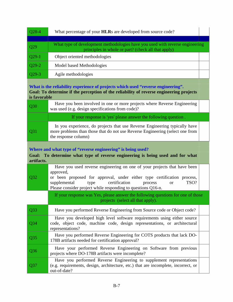
Q28-4 What percentage of your HLRs are developed from source code?
Q29 What type of development methodologies have you used with reverse engineering principles in whole or part? (check all that apply)
Q29-1 Object oriented methodologies
Q29-2 Model based Methodologies
Q29-3 Agile methodologies What is the reliability experience of projects which used “reverse engineering”. Goal: To determine if the perception of the reliability of reverse engineering projects is favorable
Q30 Have you been involved in one or more projects where Reverse Engineering was used (e.g. design specifications from code)?
If your response is 'yes' please answer the following question .
Q31 In you experience, do projects that use Reverse Engineering typically have
more problems than those that do not use Reverse Engineering (select one from the response column)
Where and what type of “reverse engineering” is being used? Goal: To determine what type of reverse engineering is being used and for what artifacts.
Q32
Have you used reverse engineering on one of your projects that have been approved, or been proposed for approval, under either type certification process, supplemental type certification process or TSO? Please consider project while responding to questions Q16-n.
If your response was Yes, please answer the following questions for one of those projects (select all that apply).
Q33 Have you performed Reverse Engineering from Source code or Object code?
Q34 Have you developed high level software requirements using either source
code, object code, machine code, design representations, or architectural representations?
Q35 Have you performed Reverse Engineering for COTS products that lack DO-178B artifacts needed for certification approval?
Q36 Have your performed Reverse Engineering on Software from previous projects where DO-178B artifacts were incomplete?
Q37 Have you performed Reverse Engineering to supplement representations
(e.g. requirements, design, architecture, etc.) that are incomplete, incorrect, or out-of-date?
B-7
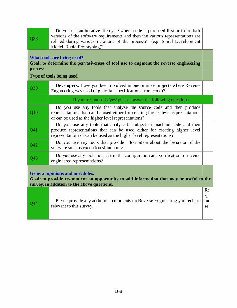
Q38
Do you use an iterative life cycle where code is produced first or from draft versions of the software requirements and then the various representations are refined during various iterations of the process? (e.g. Spiral Development Model, Rapid Prototyping)?
What tools are being used? Goal: to determine the pervasiveness of tool use to augment the reverse engineering process
Type of tools being used
Q39 Developers: Have you been involved in one or more projects where Reverse Engineering was used (e.g. design specifications from code)?
If your response is 'yes' please answer the following questions
Q40 Do you use any tools that analyze the source code and then produce
representations that can be used either for creating higher level representations or can be used as the higher level representations?
Q41 Do you use any tools that analyze the object or machine code and then
produce representations that can be used either for creating higher level representations or can be used as the higher level representations?
Q42 Do you use any tools that provide information about the behavior of the software such as execution simulators?
Q43 Do you use any tools to assist in the configuration and verification of reverse engineered representations?
General opinions and anecdotes. Goal: to provide respondent an opportunity to add information that may be useful to the survey, in addition to the above questions.
Q44 Please provide any additional comments on Reverse Engineering you feel are relevant to this survey.
Response
B-8
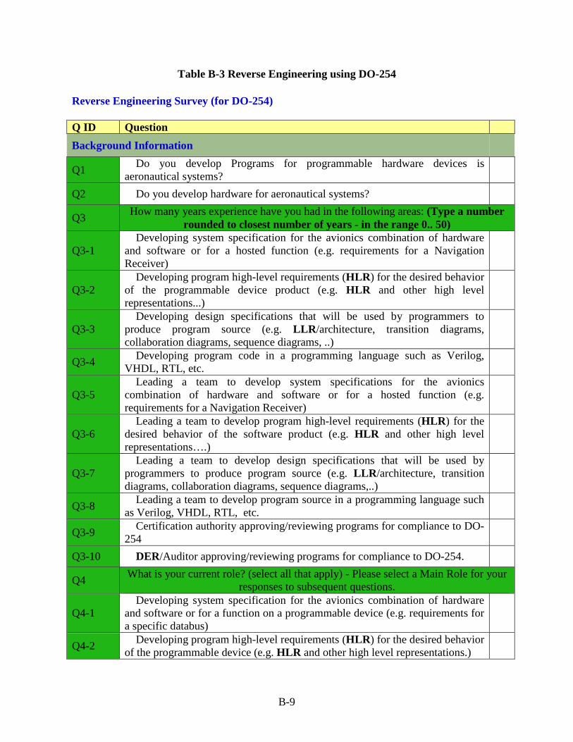
Table B-3 Reverse Engineering using DO-254 Reverse Engineering Survey (for DO-254) Q ID Question Background Information
Q1 Do you develop Programs for programmable hardware devices is aeronautical systems?
Q2 Do you develop hardware for aeronautical systems?
Q3 How many years experience have you had in the following areas: (Type a number rounded to closest number of years - in the range 0.. 50)
Q3-1 Developing system specification for the avionics combination of hardware
and software or for a hosted function (e.g. requirements for a Navigation Receiver)
Q3-2 Developing program high-level requirements (HLR) for the desired behavior
of the programmable device product (e.g. HLR and other high level representations...)
Q3-3 Developing design specifications that will be used by programmers to
produce program source (e.g. LLR/architecture, transition diagrams, collaboration diagrams, sequence diagrams, ..)
Q3-4 Developing program code in a programming language such as Verilog, VHDL, RTL, etc.
Q3-5 Leading a team to develop system specifications for the avionics
combination of hardware and software or for a hosted function (e.g. requirements for a Navigation Receiver)
Q3-6 Leading a team to develop program high-level requirements (HLR) for the
desired behavior of the software product (e.g. HLR and other high level representations….)
Q3-7 Leading a team to develop design specifications that will be used by
programmers to produce program source (e.g. LLR/architecture, transition diagrams, collaboration diagrams, sequence diagrams,..)
Q3-8 Leading a team to develop program source in a programming language such as Verilog, VHDL, RTL, etc.
Q3-9 Certification authority approving/reviewing programs for compliance to DO-254
Q3-10 DER/Auditor approving/reviewing programs for compliance to DO-254.
Q4 What is your current role? (select all that apply) - Please select a Main Role for your responses to subsequent questions.
Q4-1 Developing system specification for the avionics combination of hardware
and software or for a function on a programmable device (e.g. requirements for a specific databus)
Q4-2 Developing program high-level requirements (HLR) for the desired behavior of the programmable device (e.g. HLR and other high level representations.)
B-9
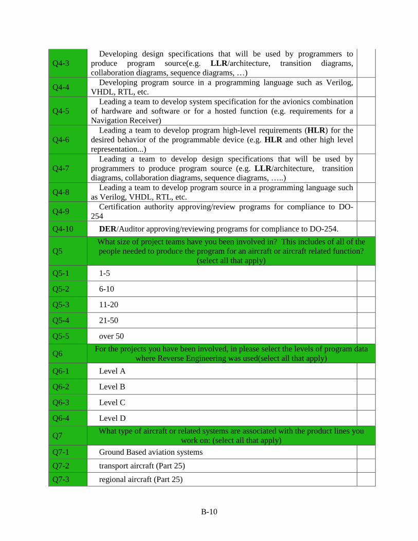
Q4-3 Developing design specifications that will be used by programmers to
produce program source(e.g. LLR/architecture, transition diagrams, collaboration diagrams, sequence diagrams, …)
Q4-4 Developing program source in a programming language such as Verilog, VHDL, RTL, etc.
Q4-5 Leading a team to develop system specification for the avionics combination
of hardware and software or for a hosted function (e.g. requirements for a Navigation Receiver)
Q4-6 Leading a team to develop program high-level requirements (HLR) for the
desired behavior of the programmable device (e.g. HLR and other high level representation...)
Q4-7 Leading a team to develop design specifications that will be used by
programmers to produce program source (e.g. LLR/architecture, transition diagrams, collaboration diagrams, sequence diagrams, …..)
Q4-8 Leading a team to develop program source in a programming language such as Verilog, VHDL, RTL, etc.
Q4-9 Certification authority approving/review programs for compliance to DO-254
Q4-10 DER/Auditor approving/reviewing programs for compliance to DO-254.
Q5 What size of project teams have you been involved in? This includes of all of the people needed to produce the program for an aircraft or aircraft related function?
(select all that apply) Q5-1 1-5
Q5-2 6-10
Q5-3 11-20
Q5-4 21-50
Q5-5 over 50
Q6 For the projects you have been involved, in please select the levels of program data where Reverse Engineering was used(select all that apply)
Q6-1 Level A
Q6-2 Level B
Q6-3 Level C
Q6-4 Level D
Q7 What type of aircraft or related systems are associated with the product lines you work on: (select all that apply)
Q7-1 Ground Based aviation systems
Q7-2 transport aircraft (Part 25)
Q7-3 regional aircraft (Part 25)
B-10
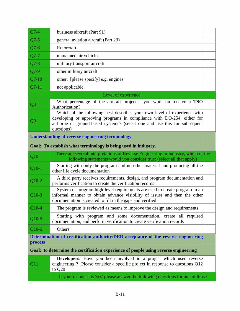
Q7-4 business aircraft (Part 91)
Q7-5 general aviation aircraft (Part 23)
Q7-6 Rotorcraft
Q7-7 unmanned air vehicles
Q7-8 military transport aircraft
Q7-9 other military aircraft
Q7-10 other, [please specify] e.g. engines.
Q7-11 not applicable
Level of experience
Q8 What percentage of the aircraft projects you work on receive a TSO Authorization?
Q9
Which of the following best describes your own level of experience with developing or approving programs in compliance with DO-254, either for airborne or ground-based systems? (select one and use this for subsequent questions)
Understanding of reverse engineering terminology
Goal: To establish what terminology is being used in industry.
Q10 There are several interpretations of Reverse Engineering in Industry, which of the following statements would you consider true: (select all that apply)
Q10-1 Starting with only the program and no other material and producing all the other life cycle documentation
Q10-2 A third party receives requirements, design, and program documentation and performs verification to create the verification records
Q10-3 System or program high-level requirements are used to create program in an
informal manner to obtain advance visibility of issues and then the other documentation is created to fill in the gaps and verified
Q10-4 The program is reviewed as means to improve the design and requirements
Q10-5 Starting with program and some documentation, create all required documentation, and perform verification to create verification records
Q10-6 Others Determination of certification authority/DER acceptance of the reverse engineering process
Goal: to determine the certification experience of people using reverse engineering
Q11 Developers: Have you been involved in a project which used reverse
engineering ? Please consider a specific project in response to questions Q12 to Q20
If your response is 'yes' please answer the following questions for one of those
B-11
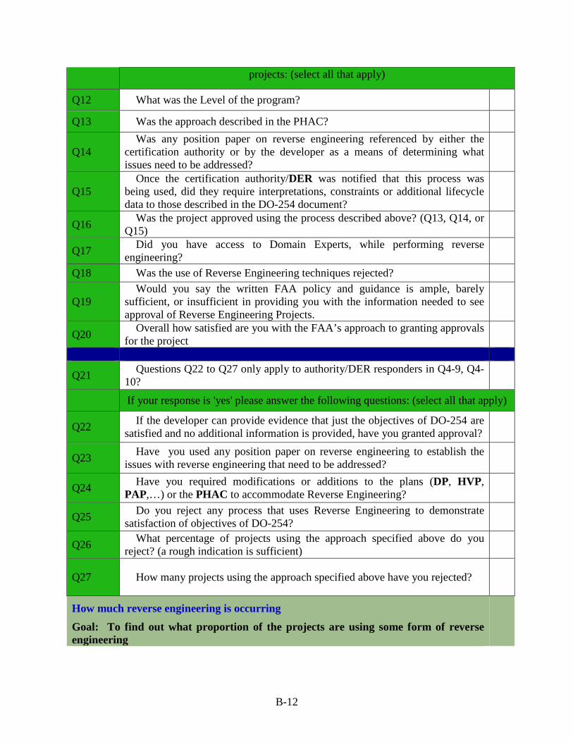
projects: (select all that apply)
Q12 What was the Level of the program?
Q13 Was the approach described in the PHAC?
Q14 Was any position paper on reverse engineering referenced by either the
certification authority or by the developer as a means of determining what issues need to be addressed?
Q15 Once the certification authority/DER was notified that this process was
being used, did they require interpretations, constraints or additional lifecycle data to those described in the DO-254 document?
Q16 Was the project approved using the process described above? (Q13, Q14, or Q15)
Q17 Did you have access to Domain Experts, while performing reverse engineering?
Q18 Was the use of Reverse Engineering techniques rejected?
Q19 Would you say the written FAA policy and guidance is ample, barely
sufficient, or insufficient in providing you with the information needed to see approval of Reverse Engineering Projects.
Q20 Overall how satisfied are you with the FAA’s approach to granting approvals for the project
Q21 Questions Q22 to Q27 only apply to authority/DER responders in Q4-9, Q4-10?
If your response is 'yes' please answer the following questions: (select all that apply)
Q22 If the developer can provide evidence that just the objectives of DO-254 are satisfied and no additional information is provided, have you granted approval?
Q23 Have you used any position paper on reverse engineering to establish the issues with reverse engineering that need to be addressed?
Q24 Have you required modifications or additions to the plans (DP, HVP, PAP,…) or the PHAC to accommodate Reverse Engineering?
Q25 Do you reject any process that uses Reverse Engineering to demonstrate satisfaction of objectives of DO-254?
Q26 What percentage of projects using the approach specified above do you reject? (a rough indication is sufficient)
Q27 How many projects using the approach specified above have you rejected?
How much reverse engineering is occurring
Goal: To find out what proportion of the projects are using some form of reverse engineering
B-12
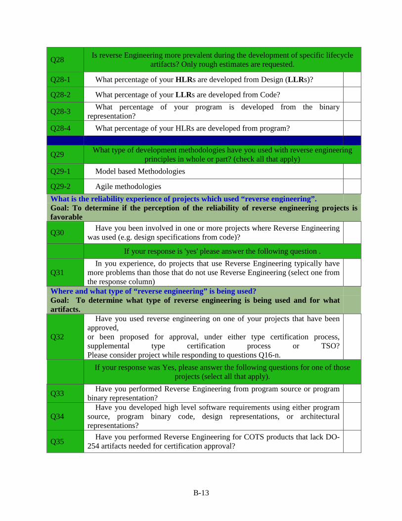
Q28 Is reverse Engineering more prevalent during the development of specific lifecycle artifacts? Only rough estimates are requested.
Q28-1 What percentage of your HLRs are developed from Design (LLRs)?
Q28-2 What percentage of your LLRs are developed from Code?
Q28-3 What percentage of your program is developed from the binary representation?
Q28-4 What percentage of your HLRs are developed from program?
Q29 What type of development methodologies have you used with reverse engineering principles in whole or part? (check all that apply)
Q29-1 Model based Methodologies
Q29-2 Agile methodologies What is the reliability experience of projects which used “reverse engineering”. Goal: To determine if the perception of the reliability of reverse engineering projects is favorable
Q30 Have you been involved in one or more projects where Reverse Engineering was used (e.g. design specifications from code)?
If your response is 'yes' please answer the following question .
Q31 In you experience, do projects that use Reverse Engineering typically have
more problems than those that do not use Reverse Engineering (select one from the response column)
Where and what type of “reverse engineering” is being used? Goal: To determine what type of reverse engineering is being used and for what artifacts.
Q32
Have you used reverse engineering on one of your projects that have been approved, or been proposed for approval, under either type certification process, supplemental type certification process or TSO? Please consider project while responding to questions Q16-n.
If your response was Yes, please answer the following questions for one of those projects (select all that apply).
Q33 Have you performed Reverse Engineering from program source or program binary representation?
Q34 Have you developed high level software requirements using either program
source, program binary code, design representations, or architectural representations?
Q35 Have you performed Reverse Engineering for COTS products that lack DO-254 artifacts needed for certification approval?
B-13
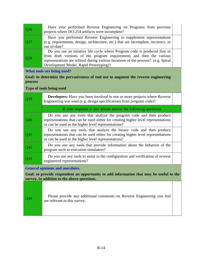
Q36 Have your performed Reverse Engineering on Programs from previous projects where DO-254 artifacts were incomplete?
Q37 Have you performed Reverse Engineering to supplement representations
(e.g. requirements, design, architecture, etc.) that are incomplete, incorrect, or out-of-date?
Q38
Do you use an iterative life cycle where Program code is produced first or from draft versions of the program requirements and then the various representations are refined during various iterations of the process? (e.g. Spiral Development Model, Rapid Prototyping)?
What tools are being used? Goal: to determine the pervasiveness of tool use to augment the reverse engineering process
Type of tools being used
Q39 Developers: Have you been involved in one or more projects where Reverse Engineering was used (e.g. design specifications from program code)?
If your response is 'yes' please answer the following questions
Q40 Do you use any tools that analyze the program code and then produce
representations that can be used either for creating higher level representations or can be used as the higher level representations?
Q41 Do you use any tools that analyze the binary code and then produce
representations that can be used either for creating higher level representations or can be used as the higher level representations?
Q42 Do you use any tools that provide information about the behavior of the program such as execution simulators?
Q43 Do you use any tools to assist in the configuration and verification of reverse engineered representations?
General opinions and anecdotes. Goal: to provide respondent an opportunity to add information that may be useful to the survey, in addition to the above questions.
Q44 Please provide any additional comments on Reverse Engineering you feel are relevant to this survey.
B-14
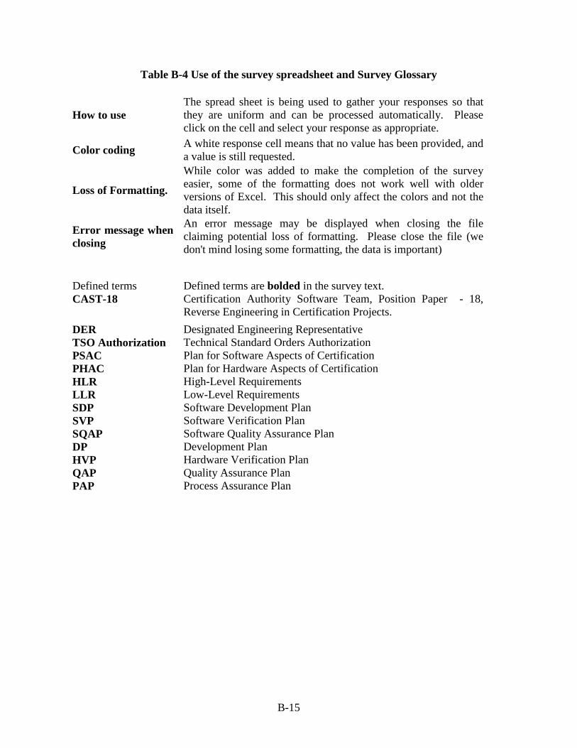
Table B-4 Use of the survey spreadsheet and Survey Glossary
How to use The spread sheet is being used to gather your responses so that they are uniform and can be processed automatically. Please click on the cell and select your response as appropriate.
Color coding A white response cell means that no value has been provided, and a value is still requested.
Loss of Formatting.
While color was added to make the completion of the survey easier, some of the formatting does not work well with older versions of Excel. This should only affect the colors and not the data itself.
Error message when closing
An error message may be displayed when closing the file claiming potential loss of formatting. Please close the file (we don't mind losing some formatting, the data is important)
Defined terms Defined terms are bolded in the survey text. CAST-18 Certification Authority Software Team, Position Paper - 18,
Reverse Engineering in Certification Projects. DER Designated Engineering Representative TSO Authorization Technical Standard Orders Authorization PSAC Plan for Software Aspects of Certification PHAC Plan for Hardware Aspects of Certification HLR High-Level Requirements LLR Low-Level Requirements SDP Software Development Plan SVP Software Verification Plan SQAP Software Quality Assurance Plan DP Development Plan HVP Hardware Verification Plan QAP Quality Assurance Plan PAP Process Assurance Plan
B-15
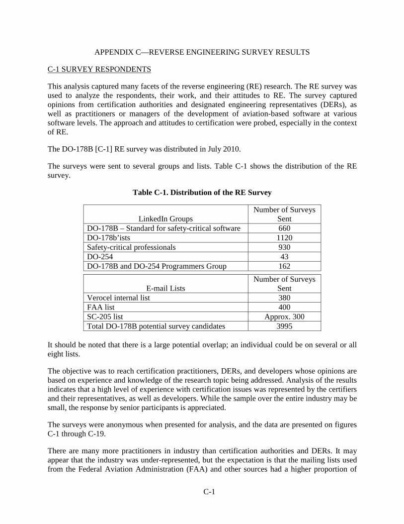
APPENDIX C—REVERSE ENGINEERING SURVEY RESULTS
C-1 SURVEY RESPONDENTS
This analysis captured many facets of the reverse engineering (RE) research. The RE survey was used to analyze the respondents, their work, and their attitudes to RE. The survey captured opinions from certification authorities and designated engineering representatives (DERs), as well as practitioners or managers of the development of aviation-based software at various software levels. The approach and attitudes to certification were probed, especially in the context of RE.
The DO-178B [C-1] RE survey was distributed in July 2010.
The surveys were sent to several groups and lists. Table C-1 shows the distribution of the RE survey.
Table C-1. Distribution of the RE Survey
LinkedIn Groups Number of Surveys
Sent DO-178B – Standard for safety-critical software 660 DO-178b’ists 1120 Safety-critical professionals 930 DO-254 43 DO-178B and DO-254 Programmers Group 162
E-mail Lists Number of Surveys
Sent Verocel internal list 380 FAA list 400 SC-205 list Approx. 300 Total DO-178B potential survey candidates 3995
It should be noted that there is a large potential overlap; an individual could be on several or all eight lists.
The objective was to reach certification practitioners, DERs, and developers whose opinions are based on experience and knowledge of the research topic being addressed. Analysis of the results indicates that a high level of experience with certification issues was represented by the certifiers and their representatives, as well as developers. While the sample over the entire industry may be small, the response by senior participants is appreciated.
The surveys were anonymous when presented for analysis, and the data are presented on figures C-1 through C-19.
There are many more practitioners in industry than certification authorities and DERs. It may appear that the industry was under-represented, but the expectation is that the mailing lists used from the Federal Aviation Administration (FAA) and other sources had a higher proportion of
C-1
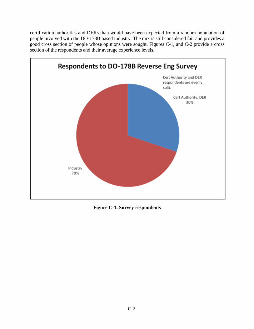
certification authorities and DERs than would have been expected from a random population of people involved with the DO-178B based industry. The mix is still considered fair and provides a good cross section of people whose opinions were sought. Figures C-1, and C-2 provide a cross section of the respondents and their average experience levels.
Figure C-1. Survey respondents
C-2
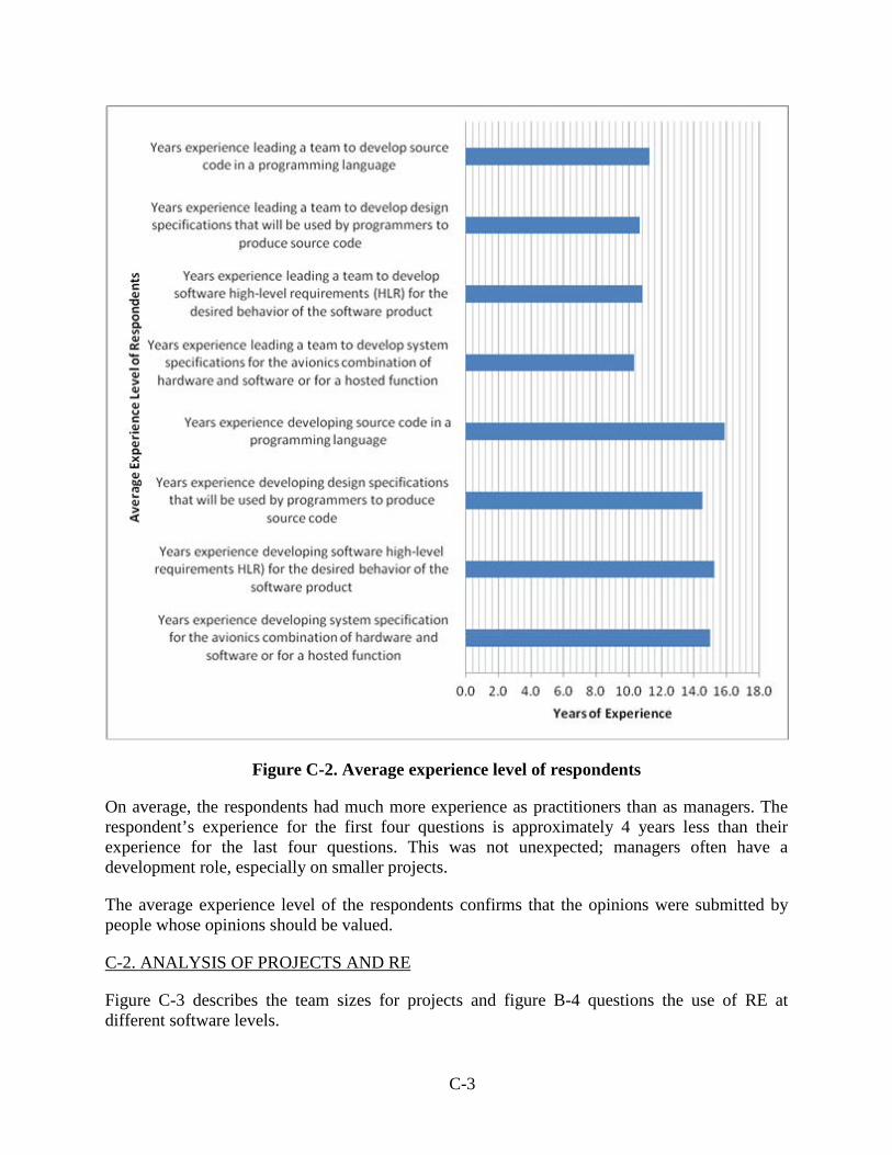
Figure C-2. Average experience level of respondents
On average, the respondents had much more experience as practitioners than as managers. The respondent’s experience for the first four questions is approximately 4 years less than their experience for the last four questions. This was not unexpected; managers often have a development role, especially on smaller projects.
The average experience level of the respondents confirms that the opinions were submitted by people whose opinions should be valued.
C-2. ANALYSIS OF PROJECTS AND RE
Figure C-3 describes the team sizes for projects and figure B-4 questions the use of RE at different software levels.
Years of Experience
Aver
age
Expe
rienc
e Le
vel o
f Res
pond
ents
C-3
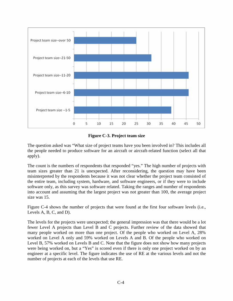
Figure C-3. Project team size
The question asked was “What size of project teams have you been involved in? This includes all the people needed to produce software for an aircraft or aircraft-related function (select all that apply).
The count is the numbers of respondents that responded “yes.” The high number of projects with team sizes greater than 21 is unexpected. After reconsidering, the question may have been misinterpreted by the respondents because it was not clear whether the project team consisted of the entire team, including system, hardware, and software engineers, or if they were to include software only, as this survey was software related. Taking the ranges and number of respondents into account and assuming that the largest project was not greater than 100, the average project size was 15.
Figure C-4 shows the number of projects that were found at the first four software levels (i.e., Levels A, B, C, and D).
The levels for the projects were unexpected; the general impression was that there would be a lot fewer Level A projects than Level B and C projects. Further review of the data showed that many people worked on more than one project. Of the people who worked on Level A, 28% worked on Level A only and 59% worked on Levels A and B. Of the people who worked on Level B, 57% worked on Levels B and C. Note that the figure does not show how many projects were being worked on, but a “Yes” is scored even if there is only one project worked on by an engineer at a specific level. The figure indicates the use of RE at the various levels and not the number of projects at each of the levels that use RE.
C-4
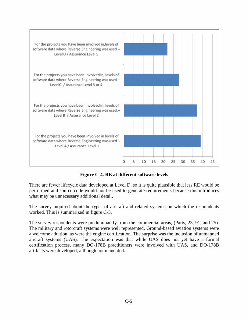
Figure C-4. RE at different software levels
There are fewer lifecycle data developed at Level D, so it is quite plausible that less RE would be performed and source code would not be used to generate requirements because this introduces what may be unnecessary additional detail.
The survey inquired about the types of aircraft and related systems on which the respondents worked. This is summarized in figure C-5.
The survey respondents were predominantly from the commercial areas, (Parts, 23, 91, and 25). The military and rotorcraft systems were well represented. Ground-based aviation systems were a welcome addition, as were the engine certification. The surprise was the inclusion of unmanned aircraft systems (UAS). The expectation was that while UAS does not yet have a formal certification process, many DO-178B practitioners were involved with UAS, and DO-178B artifacts were developed, although not mandated.
C-5
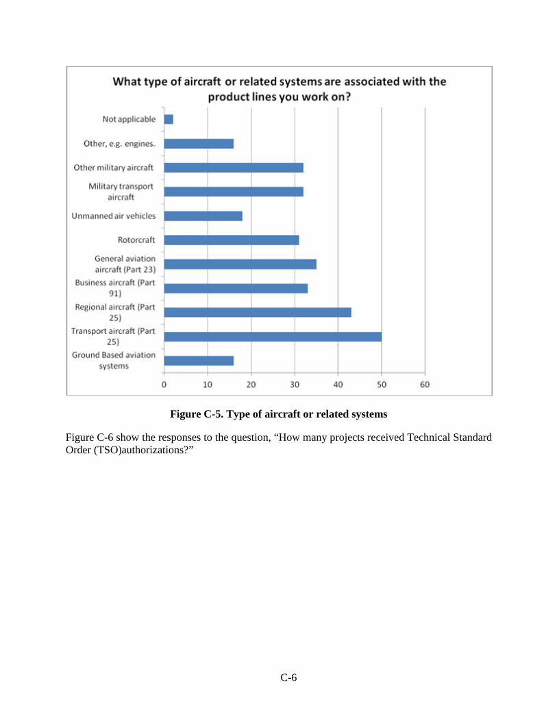
Figure C-5. Type of aircraft or related systems
Figure C-6 show the responses to the question, “How many projects received Technical Standard Order (TSO)authorizations?”
What type of aircraft or related systems are associated with the product lines you work on?
C-6
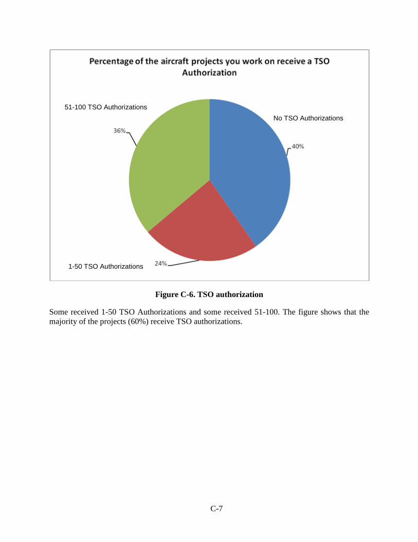
Figure C-6. TSO authorization
Some received 1-50 TSO Authorizations and some received 51-100. The figure shows that the majority of the projects (60%) receive TSO authorizations.
Series1, 0%, 29, 40%
Series1, 1-50%, 17, 24%
Series1, 51-100%, 26, 36%
Percentage of the aircraft projects you work on receive a TSO Authorization
No TSO Authorizations
1-50 TSO Authorizations
51-100 TSO Authorizations
C-7
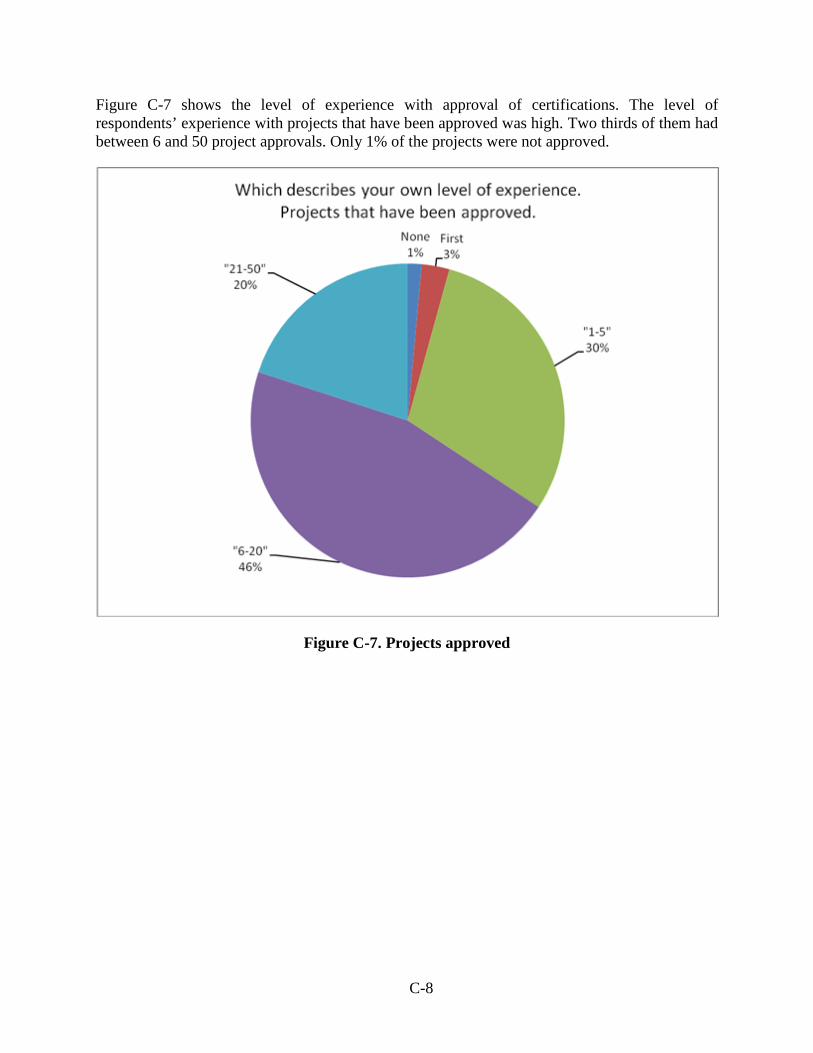
Figure C-7 shows the level of experience with approval of certifications. The level of respondents’ experience with projects that have been approved was high. Two thirds of them had between 6 and 50 project approvals. Only 1% of the projects were not approved.
Figure C-7. Projects approved
Series1, None, 1, 1% Series1, First, 2, 3%
Series1, "1-5", 21, 30%
Series1, "6-20", 32, 46%
Series1, "21-50", 14, 20%
Which describes your own level of experience. Projects that have been approved.
C-8
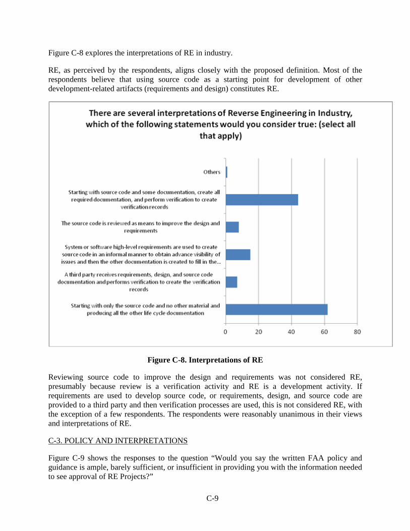
Figure C-8 explores the interpretations of RE in industry.
RE, as perceived by the respondents, aligns closely with the proposed definition. Most of the respondents believe that using source code as a starting point for development of other development-related artifacts (requirements and design) constitutes RE.
Figure C-8. Interpretations of RE
Reviewing source code to improve the design and requirements was not considered RE, presumably because review is a verification activity and RE is a development activity. If requirements are used to develop source code, or requirements, design, and source code are provided to a third party and then verification processes are used, this is not considered RE, with the exception of a few respondents. The respondents were reasonably unanimous in their views and interpretations of RE.
C-3. POLICY AND INTERPRETATIONS
Figure C-9 shows the responses to the question “Would you say the written FAA policy and guidance is ample, barely sufficient, or insufficient in providing you with the information needed to see approval of RE Projects?”
There are several interpretations of Reverse Engineering in Industry, which of the following statements would you consider true: (select all
that apply)
C-9
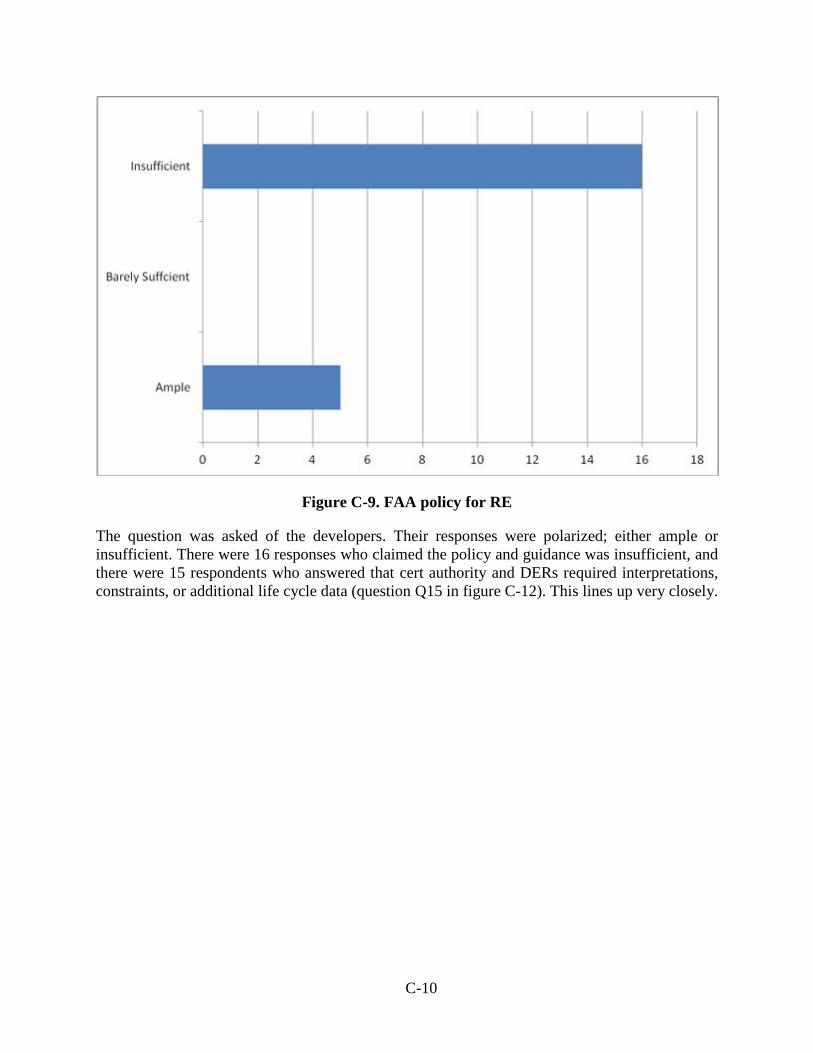
Figure C-9. FAA policy for RE
The question was asked of the developers. Their responses were polarized; either ample or insufficient. There were 16 responses who claimed the policy and guidance was insufficient, and there were 15 respondents who answered that cert authority and DERs required interpretations, constraints, or additional life cycle data (question Q15 in figure C-12). This lines up very closely.
C-10
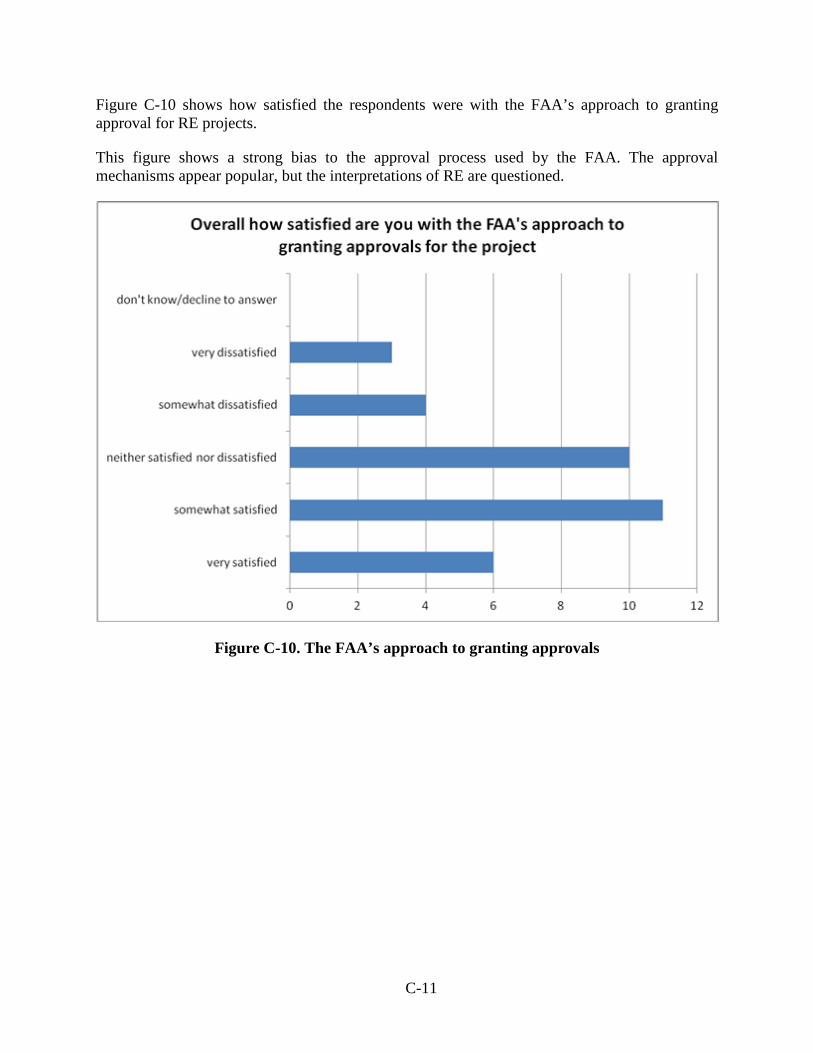
Figure C-10 shows how satisfied the respondents were with the FAA’s approach to granting approval for RE projects.
This figure shows a strong bias to the approval process used by the FAA. The approval mechanisms appear popular, but the interpretations of RE are questioned.
Figure C-10. The FAA’s approach to granting approvals
Overall how satisfied are you with the FAA's approach to granting approvals for the project
C-11
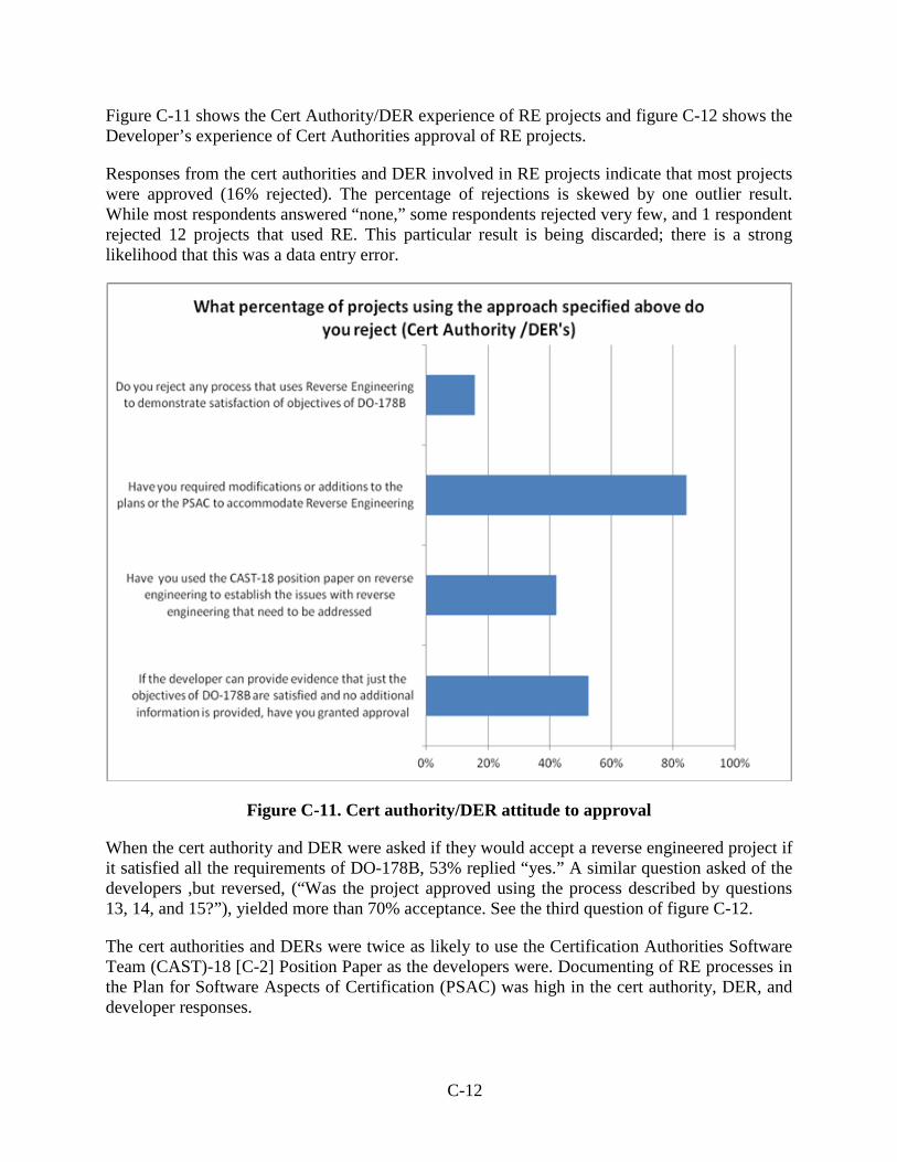
Figure C-11 shows the Cert Authority/DER experience of RE projects and figure C-12 shows the Developer’s experience of Cert Authorities approval of RE projects.
Responses from the cert authorities and DER involved in RE projects indicate that most projects were approved (16% rejected). The percentage of rejections is skewed by one outlier result. While most respondents answered “none,” some respondents rejected very few, and 1 respondent rejected 12 projects that used RE. This particular result is being discarded; there is a strong likelihood that this was a data entry error.
Figure C-11. Cert authority/DER attitude to approval
When the cert authority and DER were asked if they would accept a reverse engineered project if it satisfied all the requirements of DO-178B, 53% replied “yes.” A similar question asked of the developers ,but reversed, (“Was the project approved using the process described by questions 13, 14, and 15?”), yielded more than 70% acceptance. See the third question of figure C-12.
The cert authorities and DERs were twice as likely to use the Certification Authorities Software Team (CAST)-18 [C-2] Position Paper as the developers were. Documenting of RE processes in the Plan for Software Aspects of Certification (PSAC) was high in the cert authority, DER, and developer responses.
What percentage of projects using the approach specified above do you reject (Cert Authority /DER's)
C-12
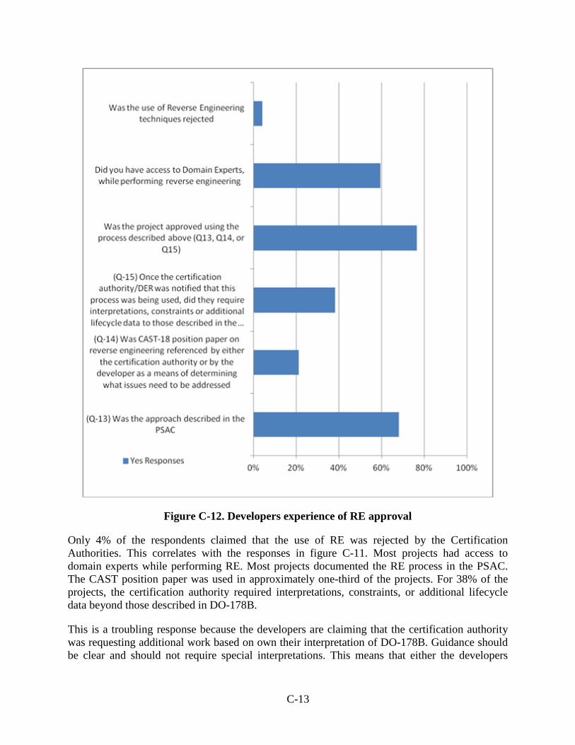
Figure C-12. Developers experience of RE approval
Only 4% of the respondents claimed that the use of RE was rejected by the Certification Authorities. This correlates with the responses in figure C-11. Most projects had access to domain experts while performing RE. Most projects documented the RE process in the PSAC. The CAST position paper was used in approximately one-third of the projects. For 38% of the projects, the certification authority required interpretations, constraints, or additional lifecycle data beyond those described in DO-178B.
This is a troubling response because the developers are claiming that the certification authority was requesting additional work based on own their interpretation of DO-178B. Guidance should be clear and should not require special interpretations. This means that either the developers
(Q-13) Was theapproach…
C-13
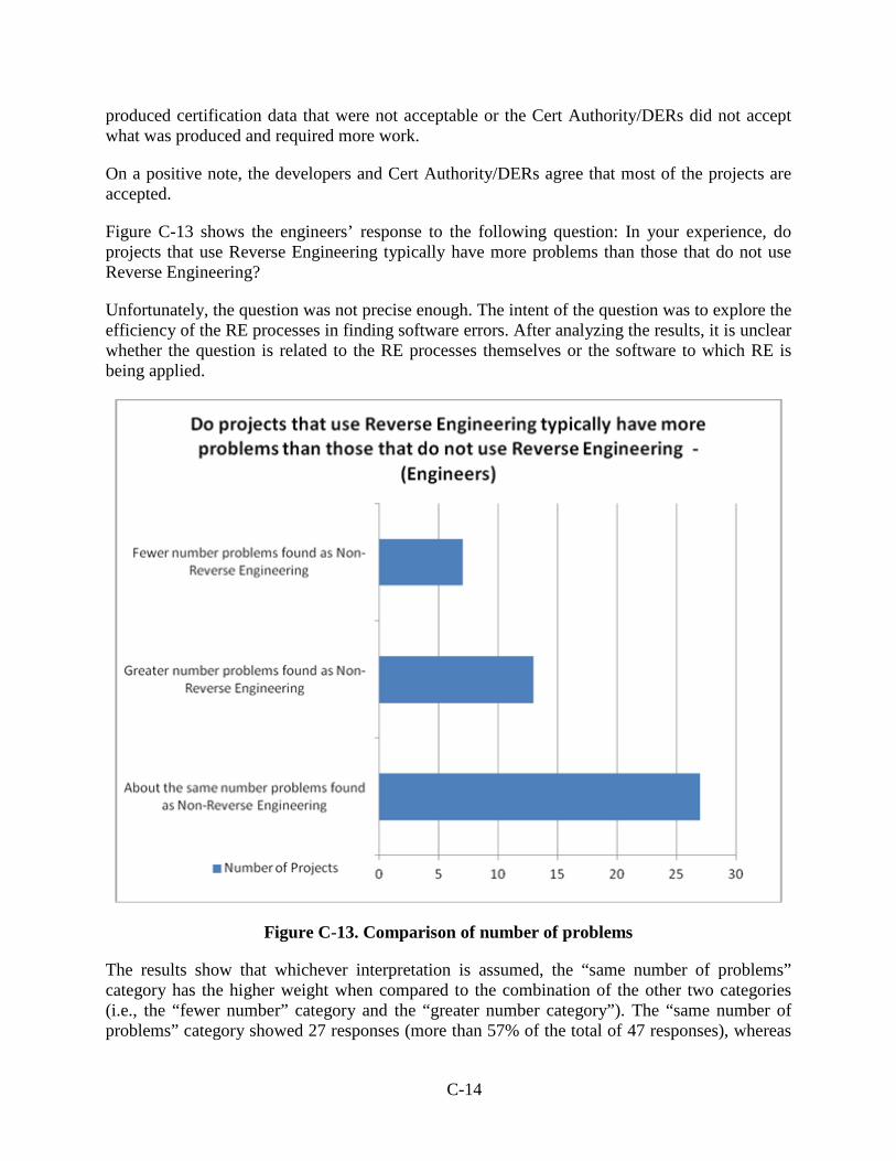
produced certification data that were not acceptable or the Cert Authority/DERs did not accept what was produced and required more work.
On a positive note, the developers and Cert Authority/DERs agree that most of the projects are accepted.
Figure C-13 shows the engineers’ response to the following question: In your experience, do projects that use Reverse Engineering typically have more problems than those that do not use Reverse Engineering?
Unfortunately, the question was not precise enough. The intent of the question was to explore the efficiency of the RE processes in finding software errors. After analyzing the results, it is unclear whether the question is related to the RE processes themselves or the software to which RE is being applied.
Figure C-13. Comparison of number of problems
The results show that whichever interpretation is assumed, the “same number of problems” category has the higher weight when compared to the combination of the other two categories (i.e., the “fewer number” category and the “greater number category”). The “same number of problems” category showed 27 responses (more than 57% of the total of 47 responses), whereas
Do projects that use Reverse Engineering typically have more problems than those that do not use Reverse Engineering -
(Engineers)
About the same…
C-14
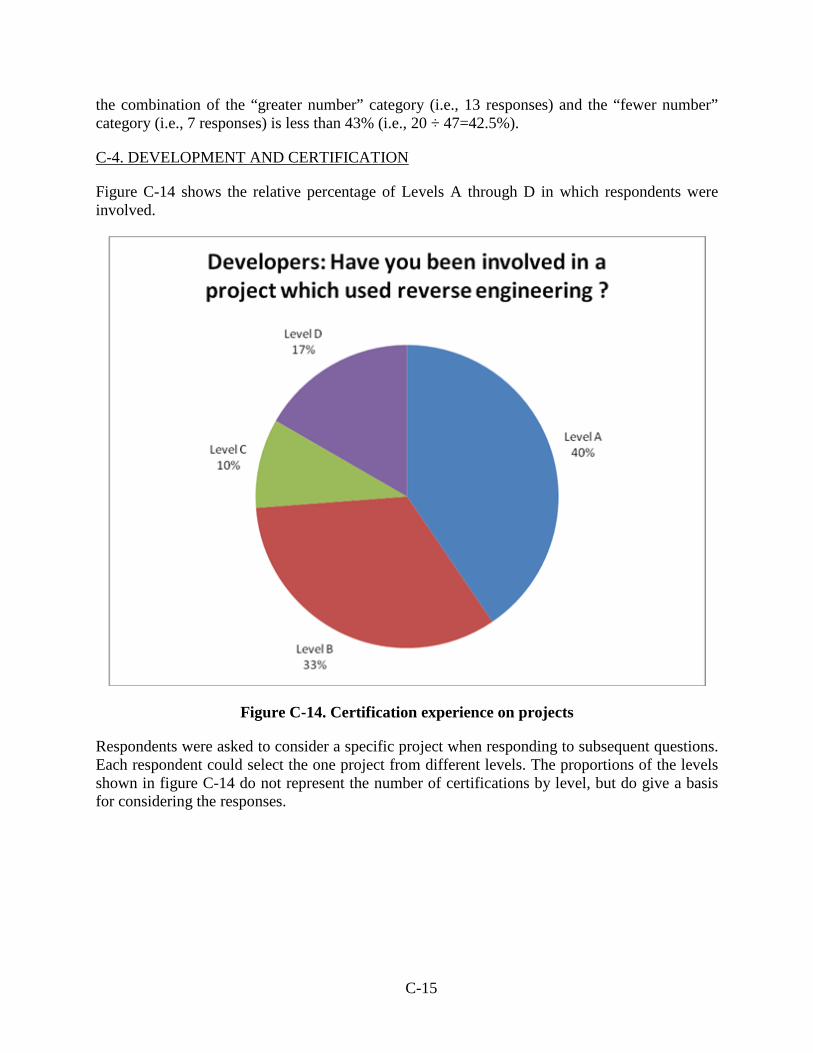
the combination of the “greater number” category (i.e., 13 responses) and the “fewer number” category (i.e., 7 responses) is less than 43% (i.e., 20 ÷ 47=42.5%).
C-4. DEVELOPMENT AND CERTIFICATION
Figure C-14 shows the relative percentage of Levels A through D in which respondents were involved.
Figure C-14. Certification experience on projects
Respondents were asked to consider a specific project when responding to subsequent questions. Each respondent could select the one project from different levels. The proportions of the levels shown in figure C-14 do not represent the number of certifications by level, but do give a basis for considering the responses.
Series1, Level A, 17, 40%
Series1, Level B, 14, 33%
Series1, Level C, 4, 10%
Series1, Level D, 7, 17%
Developers: Have you been involved in a project which used reverse engineering ?
C-15
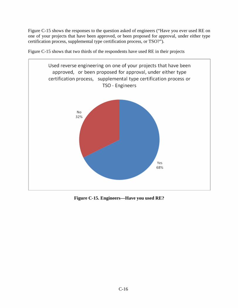
Figure C-15 shows the responses to the question asked of engineers (“Have you ever used RE on one of your projects that have been approved, or been proposed for approval, under either type certification process, supplemental type certification process, or TSO?”).
Figure C-15 shows that two thirds of the respondents have used RE in their projects
Figure C-15. Engineers—Have you used RE?
Approved, Yes, 44, 68%
Approved, No, 21, 32%
Used reverse engineering on one of your projects that have been approved, or been proposed for approval, under either type
certification process, supplemental type certification process or TSO - Engineers
C-16
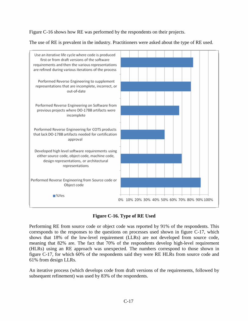
Figure C-16 shows how RE was performed by the respondents on their projects.
The use of RE is prevalent in the industry. Practitioners were asked about the type of RE used.
Figure C-16. Type of RE Used
Performing RE from source code or object code was reported by 91% of the respondents. This corresponds to the responses to the questions on processes used shown in figure C-17, which shows that 18% of the low-level requirement (LLRs) are not developed from source code, meaning that 82% are. The fact that 70% of the respondents develop high-level requirement (HLRs) using an RE approach was unexpected. The numbers correspond to those shown in figure C-17, for which 60% of the respondents said they were RE HLRs from source code and 61% from design LLRs.
An iterative process (which develops code from draft versions of the requirements, followed by subsequent refinement) was used by 83% of the respondents.
Per…
C-17
Between 67% and 80% of the respondents used RE to supplement information developed, either on new projects or on previous projects that were being adapted.
Only 50% of the respondents used RE on commercial off-the-shelf (COTS) products. This number is lower than the developed software, but this could be because COTS manufacturers sometimes provide certification packages for the software, which represents a part of the embedded software used in aviation-based systems, and not all of the respondents may be involved with the COTS components.
Figure C-17 shows the response to the questions which probed how much RE was occurring and during which development phases. The respondents were asked for simple categorization; none, less than average, and more than average.
The development of HLRs from source code and design specifications was almost identical, and approximately 60% of the respondents admitted to some level of RE of HLRs. This is unexpectedly high, because extracting the black-box behavior to the external interfaces of the software by analyzing the software is difficult and expensive.
C-18
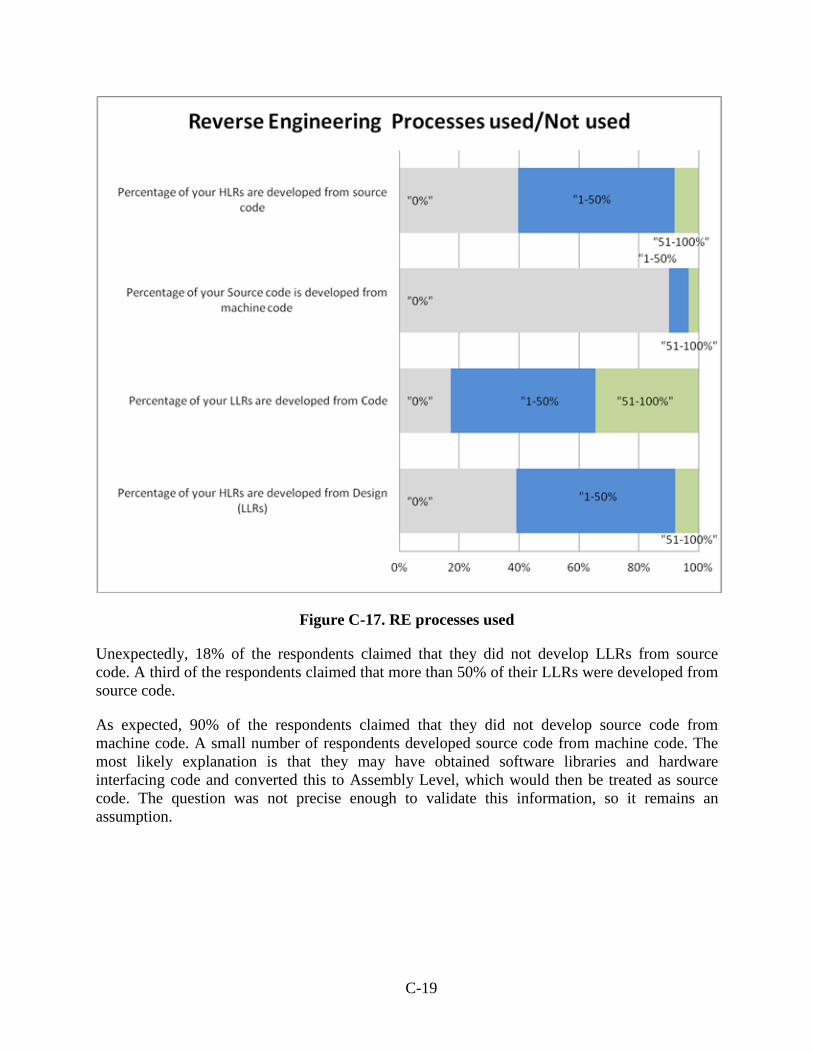
Figure C-17. RE processes used
Unexpectedly, 18% of the respondents claimed that they did not develop LLRs from source code. A third of the respondents claimed that more than 50% of their LLRs were developed from source code.
As expected, 90% of the respondents claimed that they did not develop source code from machine code. A small number of respondents developed source code from machine code. The most likely explanation is that they may have obtained software libraries and hardware interfacing code and converted this to Assembly Level, which would then be treated as source code. The question was not precise enough to validate this information, so it remains an assumption.
"0%", Percentage of your HLRs are
developed from Design (LLRs), 25
"0%", Percentage of your LLRs are
developed from Code, 11
"0%", Percentage of your Source code is
developed from machine code, 55
"0%", Percentage of your HLRs are
developed from source code, 25
"1-50%, Percentage of your HLRs are developed from Design (LLRs), 34
"1-50%, Percentage of your LLRs are developed from
Code, 31
"1-50%, Percentage of your Source code is developed from machine code, 4
"1-50%, Percentage of your HLRs are developed from source code, 33
"51-100%", Percentage of your HLRs are developed
from Design (LLRs), 5
"51-100%", Percentage of your LLRs are developed
from Code, 22
"51-100%", Percentage of your
Source code is developed from machine code, 2
"51-100%", Percentage of your HLRs are developed from source code, 5
Reverse Engineering Processes used/Not used
C-19
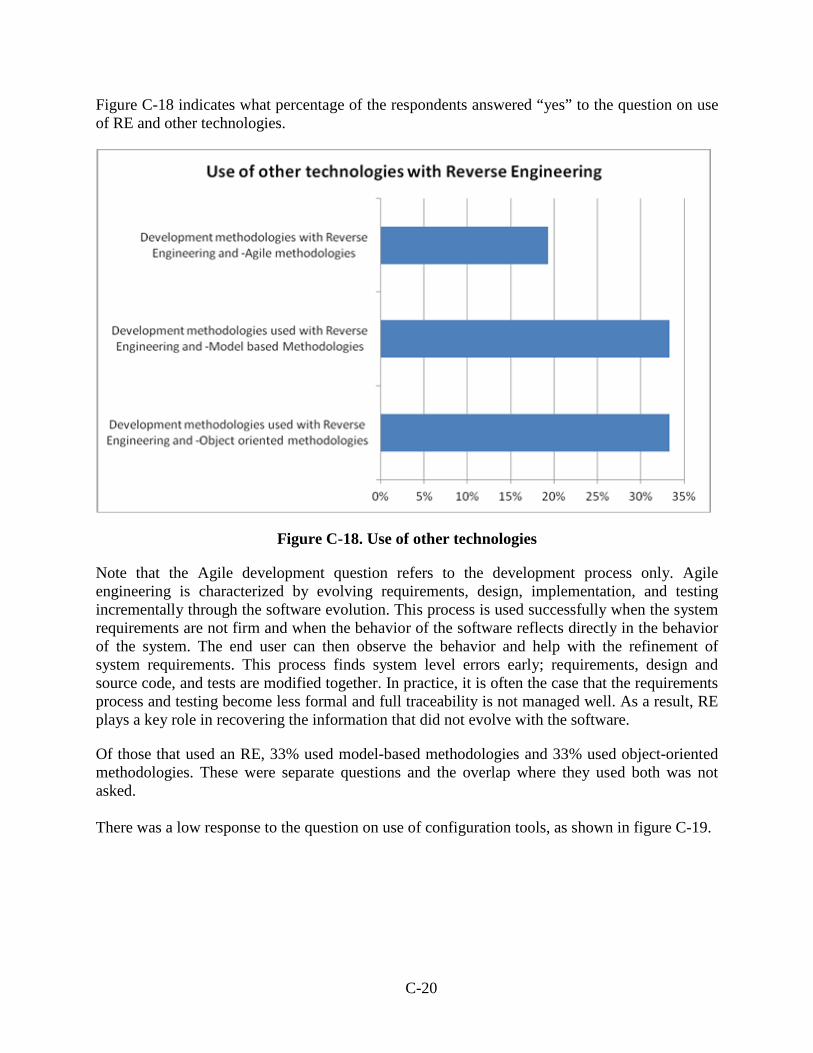
Figure C-18 indicates what percentage of the respondents answered “yes” to the question on use of RE and other technologies.
Figure C-18. Use of other technologies
Note that the Agile development question refers to the development process only. Agile engineering is characterized by evolving requirements, design, implementation, and testing incrementally through the software evolution. This process is used successfully when the system requirements are not firm and when the behavior of the software reflects directly in the behavior of the system. The end user can then observe the behavior and help with the refinement of system requirements. This process finds system level errors early; requirements, design and source code, and tests are modified together. In practice, it is often the case that the requirements process and testing become less formal and full traceability is not managed well. As a result, RE plays a key role in recovering the information that did not evolve with the software.
Of those that used an RE, 33% used model-based methodologies and 33% used object-oriented methodologies. These were separate questions and the overlap where they used both was not asked. There was a low response to the question on use of configuration tools, as shown in figure C-19.
Use of other technologies with Reverse Engineering
C-20
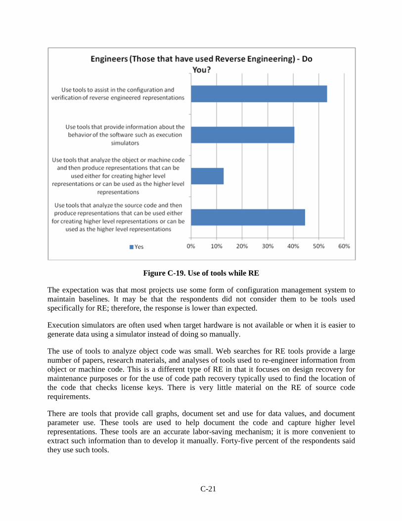
Figure C-19. Use of tools while RE
The expectation was that most projects use some form of configuration management system to maintain baselines. It may be that the respondents did not consider them to be tools used specifically for RE; therefore, the response is lower than expected.
Execution simulators are often used when target hardware is not available or when it is easier to generate data using a simulator instead of doing so manually.
The use of tools to analyze object code was small. Web searches for RE tools provide a large number of papers, research materials, and analyses of tools used to re-engineer information from object or machine code. This is a different type of RE in that it focuses on design recovery for maintenance purposes or for the use of code path recovery typically used to find the location of the code that checks license keys. There is very little material on the RE of source code requirements.
There are tools that provide call graphs, document set and use for data values, and document parameter use. These tools are used to help document the code and capture higher level representations. These tools are an accurate labor-saving mechanism; it is more convenient to extract such information than to develop it manually. Forty-five percent of the respondents said they use such tools.
Engineers (Those that have used Reverse Engineering) - Do You?
U…
C-21
REFERENCES
C-1. RTCA/00-178B, “Software Considerations in Airborne Systems and Equipment Certification,” December 1, 1992.
C-2. Certification Authorities Software Team (CAST) Position Paper 18, “Reverse
Engineering in Certification Projects” June 2003. http://www.faa.gov/aircraft/air_cert/design_approvals/ air_software/cast/cast_papers/media/cast-18.pdf.
C-22
APPENDIX D—ANALYSIS OF ISSUES AND THEIR POTENTIAL MITIGATIONS
A number of issues were identified that could be potentially created by the reverse engineering (RE) process. These issues were collected from Certification Authorities Software Team (CAST) position papers, literature, the survey, and the authors’ experience, and are summarized below along with how they can be mitigated by following the principles provided in this report.
Numbers other than CAST position paper numbers are used to make reference and discussion easier.
For the first three issues, the partial acrostic and memory aid SUNECO may be used to help the certification engineer to form a question that includes one of the three adjectives that describe the functionality in question (i.e., is it SUfficent, NEcessary, COrrect?)
D-1. MISSING FUNCTIONALITY IN THE MORE ABSTRACT LAYER
D-1.1 ISSUE DESCRIPTION
The less abstract layer (LAL) may not contain the entire solution to a system where it is used. For example, there are functions missing from the LAL that should be in the more abstract layer (MAL).
D-1.2 POTENTIAL MITIGATIONS
Going from the bottom up does not guarantee that all of the desired features at the system level will exist. Some means of introducing real system intent and establishing completeness of the reverse engineered perceived system intent is needed.
There may be several abstraction levels that are ultimately represented by source code and the final operational system. The traditional expectation is that with a formal waterfall model, an engineer is given an abstraction layer and will translate this to an LAL using only information provided by the MAL. In practice, engineers often refine the translation by adding detail, some of which is necessary and some of which is unnecessary functionality. The MAL may not specify certain robustness checks, yet by coding conventions, tradition, or experience constructs that perform null pointer checks, index boundary checks or consistency checks may be added to improve the robustness of the code.
It should be a policy that when RE is performed, all robustness checks must be called out as low-level requirements (LLRs). This would ensure that they are considered in the testing process, the source to LLR reviews, and propagated in line with DO-178B [D-1] objectives.
There are several reasons why there may be missing functionality as represented in the source code:
• The source code is incomplete through omission. During the software development process, some combinations of parameters may be coded and some level of testing performed to check the implemented functionality. The functionality may be incomplete, but the tests are performed on the parts that are already written. The engineer may fully
D-1
expect to return to the coding process to complete the functionality once a level of confidence is built up with the code written to that point. Well-organized software engineers often annotate the cases that have not been completed as null code statements with appropriate comments. This draws attention to the incomplete behavior. This may not always be the case, and it may be difficult to detect if the required functionality has been fully implemented or if the implementation has not been fully developed on the required code paths.
• The interfaces may have changed after the implementation of the source code that uses them. An example of this may be when a list in an enumeration type was first written as [RED, GREEN] and the code written to respond to a variable of this type. If the enumeration list is then changed to [RED, GREEN, AMBER] and the code is not changed, then the response of the system is undefined when the value is AMBER. This additional behavior is missing in the software, and an RE process that does not include analysis of the interface specifications will result in incomplete LLRs. The inclusion of incomplete LLRs may propagate up through the levels of abstraction and may end up with an HLR that lacks the detail necessary to detect the missing functionality.
This is not a problem for the RE. We have an oracle in this case—the interface specification. What if the system needs an AMBER (e.g., caution) and only warnings and good indications are coded? The missing LLRs should be detected during the RE process and added. A good subject matter expert (SME) would immediately recognize that the system needs this extra functionality. So how would such a mitigation appear?
“The SME shall evaluate the reverse engineered functionality to ensure it contains all of the functionality needed to perform the SME’s level view of the system functions.”
However, there may be several levels of interface specifications. Some are provided at the system level and would be understood by the SME. Other interfaces are local to the implementation (e.g., header files in the C programming language), and the SME may not understand the programming language and interfaces at that lower level (e.g., specifications of internal data structure formats). If the data structure is used consistently with no assumptions on the layout at the implementation level, then the checks of the interfaces may be performed at the local level. For example, a data structure format could be used to represent a double-linked list that holds a value at each list element. The record could contain the following components: Next, Prev, and Value. Source code that used the Next and Prev components by name would not be affected adversely if the record type was changed to Prev, Next, and Value. If some of the software functions assumed that Next was the first component in the structure, then the software could fail if the record type in the interface specification was changed.
This internal structure may not be visible at the level at which the system SME would notice. The problem is the same whether forward engineering or RE is being performed. Interface specifications are not typically reverse engineered; however, it is important that as RE uses information flow from the LAL to the MAL, interface specifications may be used to produce higher levels of abstraction and may result in descriptions of behavior that may not match the system intent.
D-2
Assumptions may be made about the functionality of integrated components. For example, the ALLOCATE function should return a location in heap memory, which contains zeros. There are three ways to implement this:
1. The ALLOCATE function obtains the required memory area and sets the contents to zero before returning a pointer to it.
2. When the heap memory is set to zero, the ALLOCATE function obtains heap locations and de-allocations are not possible.
3. When the heap memory is set to zero, the ALLOCATE function obtains heap locations and de-allocations cause the de-allocated memory to reset to zeros.
The implementation of the ALLOCATE function may assume implementation 2 or 3. In this case, it would not contain the additional functionality to set the memory locations to zero. This ALLOCATE functionality would be considered missing if the intended behavior was option 1 but the assumed behavior was 2 or 3.
In a more abstract way, this mitigation is stating that that there may be more or less functionality in the LAL than expected in the MAL. Therefore, the question is whether or not the LAL elements are SUfficient.
D-2. LACK OF ASSOCIATED BEHAVIORAL SPECIFICATIONS
D-2.1 ISSUE DESCRIPTION
If there are no associated behavioral specifications (e.g., system requirements or high-level requirements (HLRs)), there may be many solutions for requirements from source code.
D-2.2 POTENTIAL MITIGATIONS
It is important to distinguish between real system intent vs. perceived system intent developed using the RE processes.
Using RE, source code may be analyzed in an attempt to discover the intended behavior of the system. For all but the simplest of systems, various assumptions will need to be made during this process. If these assumptions are incorrect or inconsistent, the discovered intended behavior may be incorrect or inconsistent. The RE approach is performed by engineers whose experiences, knowledge, and skill levels influence the decisions they make. This may introduce some variability in the statement of intended behavior that is inherited from the source code up through the requirement levels. The variability of this intended behavior is reflected in system requirements or HLRs when reverse engineered using this process.
If the system is sufficiently simple, then the source code representation may be a very close mapping to the intended behavior. In this case, the abstractions level between source code and intended system behavior is small, and few assumptions need to be made. This means that the number of different interpretations is small and the system level requirements may be accurate.
D-3
More complex systems may have mappings that are not so obvious and more decisions need to be made. The transformation levels between the different representations may be large, making the transformation more error prone. The number of transformation levels may be increased by expanding the number of abstraction levels. While this makes the individual transformations simpler and, therefore, less error prone, there are more of them so the opportunity to make errors increases.
As RE is a manual process (although one that may be supported by tools), the engineer’s knowledge, experience, and skills will have a direct effect on the number of assumptions made during the development of the information in the abstraction level. The lower the number of assumptions, the more accurate the mapping from the less abstract layer (LAL) to the more abstract layer (MAL).
While engineers familiar with the intent of the system may make assumptions that correct the MAL in the presence of certain errors in the LAL without changing the LAL, they may restate the intended behavior in the MAL after changing the LAL. The range of abstraction levels spans the system requirements and HLRs to the source code. It may be that the systems engineers are not skilled software engineers and the software engineers are not skilled system engineers. This may result in assumptions and communication difficulties. This problem is not specific to RE during the development process.
By restating the perceived intent in the MAL, the higher level of abstraction may contain less detail. This means that the LAL may have more elements describing the intent. This may lead one to question whether or not LAL elements are NEcessary.
D-3. ERRORS IN LAL MAY PROPAGATE TO MAL
D-3.1 ISSUE DESCRIPTION
The LAL may contain errors such that the RE would create erroneous descriptions for the MAL.
D-3.2 POTENTIAL MITIGATIONS
Follow an independent verification process that checks MAL descriptions against the LAL.
The LAL may contain errors that are synthesized in the MAL using an RE process. Conversely, if a waterfall process was used, the errors may be inherited in the LAL from the MAL. The presence or absence of errors is not the issue. The real question is if there is a different class of error inserted by the RE process that would be less likely in the forward engineering process.
Certain classes of errors may be found during the RE process. If the error demonstrates inconsistencies between the software constructs, then a buffer declared with boundaries from 0 through 9 can be found, and a loop that indexes from 1 through 10 is a software error that should be found during the RE process. This problem should also be found during the verification processes, especially during code review.
D-4
A straight translation without consideration to correctness with the expectation that subsequent verification steps will find translation problems loses an opportunity to find errors. Part of this process step should be a requirement that engineers are vigilant for possible faults in the LAL.
During the source coding and debugging process, engineers often used additional code to output internal states that are not visible at the system-level boundaries. Typically, print functions are inserted to provide a history of the execution states. To obtain specific values, additional intermediate states may be added, which consolidate internal information. This debugging technique is often controlled and special compiler directives are added so that this code can be conditionally included or excluded from the operational code. As this is a human process, mistakes can be made and the resulting trace code may be left in. Function calls to reporting routines are easy to notice, but internal data collection may not be so obvious. This may result in additional code, which should be treated as dead code. If RE is used, then this code may have LLRs and, thus, HLDs written for it. Subsequent verification steps will review the requirements and the code against the requirements, followed by requirements-based tests that will verify the code against the requirements. The dead code will no longer appear as dead code. Fortunately, code that is inserted to record internal state does not change it; otherwise, it would defeat its purpose. This should be found and addressed in the verification processes. These trace calls and their corresponding data manipulations are usually simple and are often accompanied by source code comments. Note that this is something that should be recommended for the coding process, especially if RE is used—trace code must be surrounded by compiler conditional directives or comments so they are noticed as extraneous behavior that should be removed.
In a more abstract way, this is stating that there may be errors in the LAL and MAL translation; A question to raise would be whether the translation between the LAL and the MAL is COrrect.
Note that this correctness does not depend on the direction; it is required whether forward or backward translation was used.
Self-checking correctness is easier to notice because it is manifested through the lack of consistency in behavior. Code reviews should be used and should find issues, such as indexing errors, deadlock problems (in which resources are locked out of sequence and progress is held up until resources are released), overflow and underflow arithmetic errors, and loop-termination errors.
The key point is that errors can enter the system and processes should be formulated to detect these errors with the appropriate level of confidence. In some cases, the mitigations of these errors are independent of direction and some are unique to RE (e.g., the importance of identifying a qualified subject matter expert (SME)).
D-4. LACKING GUIDANCE FOR CERTIFICATION AUTHORITIES
D-4.1 ISSUE DESCRIPTION
The certification authorities do not currently have guidance that would allow a consistent evaluation of RE projects. The absence of this RE guidance may result in overly conservative interpretation and easily rejected applications.
D-5
D-4.2 POTENTIAL MITIGATIONS
The suggested guidance in an application needs to have the following attributes:
1. Addresses the issues raised in this application, including all concerns in currently published regulatory material (e.g., citing specific CAST position papers).
2. Provides rationale.
3. Will result in acceptable levels of variation in its application.
4. Is acceptable and defined by the certification authority.
5. Can be used directly by certification authorities.
This guidance could be addressed through a short RE Job Aid that can be used when RE is called out in a Plan for Software Aspects of Certification (PSAC). Even so, this approach will require collaboration with the Federal Aviation Administration.
D-5. INADEQUATE PROCESS
D-5.1 ISSUE DESCRIPTION, CAST 18[9], SECTION 4.1SECTION 4.7
The RE process is not described well in the process documentation. For example, RE is used, but only the forward process is controlled via plans. This may mean that the certification authorities may not be aware of an RE approach before significant RE work has been completed
D-5.2 POTENTIAL MITIGATIONS
There is a need to distinguish between the development and verification steps.
If a company’s plans describe only the forward process, then an additional RE plan may be an appropriate place to describe the specific RE steps to be taken on this project. The project should not wait until the Software Accomplishment Summary (SAS) to describe the deviations, but describe them up-front, and not require that the existing project plans be rewritten. An approach may be to include a separate RE software plan (RESP) or have a separately identifiable part of existing plans as the RESP. This approach would then be described in the PSAC or Plan for Hardware Aspects of Certification (PHAC), which would introduce all life cycles used on the project along with the plans that are designed to support them.
If the certification authorities see only the PSAC or PHAC, then it is essential that these documents describe the RE process directly or indirectly in the process plans.
If the development plans do not describe the RE process (the developer fails to develop standards, transition criteria, and verification criteria specific to the RE process) or if the development plans are not followed and are addressed in the SAS, then the certification authorities will not have visibility into the RE approach until late in the program.
D-6
A possible mitigation could be to repeat work using a RESP. The RESP need not contain the full company process planning information, only the processes supporting RE. The steps that are not changed still apply and can be referenced out.
D-6. WRONG LEVELS OF ABSTRACTION BETWEEN LEVELS
D-6.1 ISSUE DESCRIPTION CAST-18, SECTION 4.2, SECTION 4.5
The artifacts of RE cannot demonstrate the same level of technical and verification content as a more traditional process. There may be insufficient abstraction between the different layers of development; for example, where the HLRs are highly correlated in detail with the source code.
D-6.2 POTENTIAL MITIGATIONS
The difference in the abstraction levels of the MAL and the LAL should strike a balance between the difference between each level of abstraction and the number of abstraction levels.
The MAL should provide a representation that specifies the intended behavior of the LAL:
1. A restatement of the intended behavior at the same or similar level using a different notation is useful only for checking that the transformation was correct, not the intended behavior.
2. If the abstraction level between the MAL and LAL is too large, there will be less confidence that the process is repeatable with the same or equivalent results.
This issue also applies to forward engineering, but there may be a temptation for engineers to develop LLRs from code that specify how the code works rather than the intended behavior. This may then result in the difference between the abstraction level of the LLRs and the HLRs to be too large.
D-7. LACK OF FAMILIARITY WITH RE PROCESSES
D-7.1 ISSUE DESCRIPTION CAST-18 SECTION. 4.2
The use of RE compromises the integrity claims that could be made from a traditional forward software engineering approach.
D-7.2 POTENTIAL MITIGATIONS
Forward engineering requires a development process for which information is constructed based on given information and a creative process that has been taught or learned through experience and guidance. RE is not taught to the same extent as forward engineering at colleges and universities.
It is important that engineers performing RE processes know and understand the intent, risks, and potential errors that can result if the process is poorly executed. If a working code base is reverse engineered, the fact that the code base is working could lead to a false sense of confidence that
D-7
the software is correct and may result in a less-thorough investigation or care in developing the RE artifacts.
Additional training, work orders, mentoring, and oversight may be required to ensure that reverse engineered information is valid.
D-8. UNSTABLE PRODUCT LEADS TO INTEGRITY ISSUES
D-8.1 ISSUE DESCRIPTION CAST-18, SECTION 3.0
The object being reverse engineered is not a stable product, does not have an acceptable documented service history, and has not been developed to a standard that is comparable to DO-178B, thereby having lower ability to demonstrate integrity assurance.
D-8.2 POTENTIAL MITIGATIONS
The integrity assurance should be demonstrated by the verification processes. An unstable development process should be able to be demonstrated as acceptable, providing it is understood and permitted (e.g., agile development will have many iterations during development). The intended states of all the components should be known and understood.
If service history is used to obtain certification credit, then this should be addressed in guidance specific to service history.
Stability of the product will be discovered during the RE process. If the product is unstable and many changes to the code base are required, then the costs become very high. Developing requirements to software that is being updated uses a lot of resources as work is repeated. Through the spread of impact, the problem becomes larger and unmanageable. If the product is unstable, then the RE processes should be stopped and informal debugging steps should be taken before continuing the RE processes.
D-9. RE PROCESS IS NOT VIABLE
D-9.1 ISSUE DESCRIPTION CAST-18, SECTION 4.2
There is no justification of the RE process viability.
D-9.2 POTENTIAL MITIGATIONS
The viability has been demonstrated on a large number of projects. Of the 162 software survey respondents, 63 reported that they had been involved in a project that used RE. The respondents were experienced. Only one of the RE projects was not approved. There is a preponderance of using RE in the industry, and most of this has satisfactory conclusions. The viability of RE has been demonstrated.
D-8
D-10. ABSENCE OF SUBJECT MATER EXPERTISE
D-10.1 ISSUE DESCRIPTION CAST-18, SECTION 4.3, SECTION 4.4
There may be no or inadequate resources (e.g., SMEs, developers, or descriptive documentation) available to establish a given LAL, which is the basis for design decision, the intent of implementations, the intended problem space that the LAL was intended to solve, etc. This would make it difficult to verify any MALs developed from the LAL.
D-10.2 POTENTIAL MITIGATIONS
It is necessary to have access to SMEs because a single individual is unlikely to have all the required expertise. Typically, a number of SMEs will be used to ensure the necessary system domain knowledge and software expertise, particularly if the system is complex. A requirement is proposed that an organization identify such experts to the authorities. D-11. AIRBORNE SYSTEM REQUIREMENTS CANNOT BE TRACED DOWN
D-11.1 ISSUE DESCRIPTION CAST-18, SECTION 4.5
Airborne system requirements cannot be correlated to the reverse engineered MAL (e.g., HLRs).
D-11.2 POTENTIAL MITIGATIONS
The correlation between system requirements and HLRs depends on how the requirements are written at these two levels. Some of this correlation depends on the terminology used. For example:
• System Requirement 25: Reverse thrust shall be inhibited if there is no Weight on Wheels.
• High-Level Requirement HR1.7: Discrete REVERSE THRUST shall be set TRUE when BIT 7 of ADDRESS X’2F33 is ZERO.
To a system engineer, the system requirement may make sense, but to a software engineer, there have been a number of assumptions made that need to be resolved. In a forward engineering process, the transition from the system requirement to the HLR would be a large one because the following example would be needed:
• How is REVERSE THRUST represented? (Discrete voltage on a pin?) • Is voltage level high indicated by TRUE or FALSE? • Does TRUE represent INHIBITED? • Is Weight on Wheels represented by a bit value that can be read directly from Direct
Access Memory?
D-9
• Does the bit set to zero represent Weight on Wheels? • How quickly will the bit settings represent the real world conditions? • Is there a possibility of a bounce?
The system requirements may be underspecified; therefore, the HLR developer would be forced to request more details before the software could be written.
In an RE process, the fear is that the HLR developer could assume that the software is correct because it appears to be working and simply documents what the code is doing. When traceability between the system requirements and HLRs is established, assumptions could be made that the requirements are correct and complete.
The HLR reviewer must not make the same mistake that the HLR developer made. Reviewers should ask themselves if there is enough information in the system requirements and any other documented specifications to correlate to the HLRs.
In a forward engineering development, the translation of system requirements to HLRs is developed by a developer and reviewed by a verifier (i.e., information flows from the MAL to the LAL during development, which is then checked by a reviewer). In a RE development, the information flows from an even lower-level LAL to the LAL during development and the information flow from the MAL to LAL is checked by a reviewer.
Developers using an RE process should be trained to ask the same questions when establishing traceability between system requirements and HLRs, and should fail the HLR if the requirements cannot be traced because information is missing or is incorrect.
D-12. TRACEABILITY GAPS
D-12.1 ISSUE DESCRIPTION CAST-18, SECTION 4.5
Forward and backward traceability is not fully established in RE projects. This could result in traceability gaps. This can also make it difficult to determine whether specific functions at one abstraction layer represent unwanted or undesirable functionality (e.g., dead code).
D-12.2 POTENTIAL MITIGATIONS
When using RE, the traceability links are part of the development process and are established from the LAL to the MAL. The verification process should be independent and should confirm the correctness of the MAL to the LAL.
Traceability records relationships between objects at different abstraction levels. If these relationships are based on incorrect assumptions, then review of the objects should fail. The reviews of the objects at the different abstraction levels should use information from the MAL when checking the LAL.
D-10
The developer establishing the traceability should use the information from the LAL to establish a traceability link to the MAL. The link is bidirectional and will be confirmed during subsequent review processes.
The forward engineering process could also make assumptions, and information could be missing when traceability is established. The verification process should find these traceability problems.
If a large number of these traceability problems are found during the reviews, a deficiency in the development process could be indicated, which results in the traceability being reviewed. The development process would need to be corrected.
D-13. LACK OF CORRESPONDENCE BETWEEN LEVELS
D-13.1 ISSUE DESCRIPTION CAST-18, SECTION 4, 5
Employing RE concepts in conjunction with more-traditional approaches (e.g., forward engineering) can result in MALs that do not correspond to LALs.
D-13.2 POTENTIAL MITIGATIONS
Lack of correspondence will be discovered during independent verification between the levels.
If the MALs do not correspond to the LALs, then this should be found during the review process. If the problems are pervasive, this would indicate failures in the development processes and would need to be corrected. This problem could occur during forward engineering, RE, or a combination of both.
D-14. MISSING FUNCTIONALITY
D-14.1 ISSUE DESCRIPTION CAST-18, SECTION 4.5
The reverse engineered product may not contain all of the operational and safety functionality required at the airplane system level. This may result in imprecise traceability between the software engineered product artifacts and the system and safety requirements.
D-14.2 POTENTIAL MITIGATIONS
The absence of the operational and safety functionality should be found during the reviews of the system requirements and HLRs.
Traceability is covered in Sections D-11, D-12, and D-13.
Correct traceability should be established by the developers. If this cannot be established, the software developers should resolve this with the systems and safety engineers. Verification of the traceability should confirm that the traceability is correct and complete.
D-11
D-15. DERIVED REQUIREMENTS MAY BE MISSED
D-15.1 ISSUE DESCRIPTION CAST-18, SECTION 4. 5
The existence of derived requirements may be the result of not knowing the purpose of a specific element of an artifact that is an input to the RE process.
D-15.2 POTENTIAL MITIGATIONS
The derived requirements must be discovered and resolved.
A specific element may be inserted through an assumption that may be correct or incorrect. If an assumption is correct but not documented, this is also a problem. At the lowest level that is manually reviewed (source code), code fragments may be found that may be the result of coding, design, or requirement errors. If an RE process is used, the code insertions may result in design and requirements at the MAL that correspond to the code errors.
Some code insertions may be valid, even if they do not have corresponding requirements. For example, an operating system function that expects a task pointer as a parameter may check to verify that the object actually passed is a task object, and the user has not passed in a semaphore or message object by mistake. Such checks verify consistency of the code and are robustness checks. Other checks may be more subtle, and the effects of their outcomes may propagate to the system interfaces by causing a system state change (like a reset).
Any artifact that is added at any level must have its behavior documented through a requirement. The requirement may be traced to expected behavior at a MAL. If this cannot be accomplished, the requirement must be documented and treated as derived in accordance with the requirements of DO-178B.
Derived requirements may be the result of a forward engineering or RE process.
D-16. MISSING INTERFACES
D-16.1 ISSUE DESCRIPTION CAST-18, SECTION 4.6
There will be missing interface descriptions that result when MAL are reverse engineered from LALs. These interfaces could be software-to-software interfaces, hardware-to-software interfaces, hardware-to-hardware interfaces, or the more abstract function-to-system interfaces. The missing interfaces could be the result of forward engineering, making assumptions, or RE and not questioning assumptions.
D-16.2 POTENTIAL MITIGATIONS
If interface descriptions are missing, they must be added.
Information will be missing during any MAL to LAL review process. If such missing information is pervasive, this will indicate a poor forward engineering or RE development process.
D-12
D-17. MISSING INFORMATION
D-17.1 ISSUE DESCRIPTION CAST-18, SECTION 4.6
User guides and porting guides may not completely describe the functions and protocols required.
D-17.2 POTENTIAL MITIGATIONS
Mitigations may happen during the forward engineering or RE process. The review process will fail if information is missing.
D-18. PLANNING FOR RE
D-18.1 ISSUE DESCRIPTION CAST-18, SECTION 4.6
Certification authorities not involved early in the planning process for RE projects can result in significant rework and the associated introduction of additional errors. This will be particularly true if the product has inadequate requirements, design, traceability, and verification documentation.
D-18.2 POTENTIAL MITIGATIONS
An RESP should be developed early or the development plan should address RE for the project and be provided to the certification authorities for review along with the other software plans.
D-19. MULTIPLE STAKEHOLDERS IN RE PROJECTS
D-19.1 ISSUE DESCRIPTION CAST-18, SECTION 4.6
Using multiple stakeholders in RE projects can result in errors due to inadequate requirements, design, traceability, verification documentation, communication gaps, configuration management shortfalls, and quality assurance shortfalls.
D-19.2 POTENTIAL MITIGATIONS
The requirements for coordination of the stakeholders should be described in project documentation and followed.
Using multiple stakeholders may have advantages in the development and certification of software. However, errors can occur whether there are many or few stakeholders. The following example criteria should be imposed on a multiple stakeholder project:
• The areas of responsibility must be clearly identified. • The processes used must be coordinated.
D-13
• The configuration management between all stakeholders must be described, coordinated, and verified.
• Problem and fault tracking between all stakeholders must be coordinated. • Information flow between the stakeholders must be controlled and tracked. • The stakeholders must possess the necessary expertise to complete the processes for
which they are responsible. • There must be open communication between stakeholders.
Multiple stakeholders with expertise in their specific areas may make a better and safer product if their effort is performed in accordance with the previously listed criteria.
Errors and failed projects using multiple stakeholders often result from inadequate training or knowledge of the DO-178B processes to be used or inadequate DO-178B processes imposed on the project.
D-20. ADDITIONAL FUNCTIONALITY REQUIRED BY SYSTEM
D-20.1 ISSUE DESCRIPTION
The situation may exist for which the systems SME is not aware of all the desired functionality. The RE process may result in desirable MAL functionality that is discovered by the RE of the LALs, and a process for the recognition and validation of such functionality should exist.
D-20.2 POTENTIAL MITIGATIONS
The RE process should ensure that the additional functionality is labeled as derived requirements and passed through to the System Safety assessment process.
An SME may not fully understand the detailed requirements during the development of a complex system.
For example, in a system for which a pulse is sent to a door latch followed by another pulse to open a door, the requirement could be:
A pulse on door latch followed by a pulse on door actuator will cause the door to swing open.
Such a system was implemented using slow actuators, and it worked. The system was then reimplemented with a newer, faster computer with a smaller, more sensitive latch. During tests, the programmer found that the latch was not releasing for a long enough time and the door could not swing open. The previous latch had a greater moment of inertia, which held the latch open long enough for the door to swing open. The new latch, being more responsive, opened, but closed again before the door could be opened. To solve the problem, the programmer added a delay loop so that the latch would be held open for a longer time.
D-14
This new functionality solved the immediate problem, but it was not reported back to the SME and was deemed a requirement to make the latch work correctly.
Unfortunately, the increased current in the wire connected to the latch caused local heating, which was not expected, and the heat buildup caused a fire hazard.
The problem stemmed from the addition of functionality that was not requested by the system requirements. The fix by the programmer was reverse engineered. Functionality was added not using information flowing from the MAL.
D-15
APPENDIX E—VALIDATION OF FRAMEWORK FOR SOFTWARE
Validation of the proposed framework for software was achieved with a project that had already been accepted by the Federal Aviation Administration (FAA) and through review of the results, the performance of the completeness checks and the execution of case studies. This validation demonstrates the applicability and efficacy of the proposed framework for software. E-1. VALIDATE FRAMEWORK
As stated previously in this report, a project that had already been accepted by the FAA was evaluated and assessed against the framework. The plans applied to the standards were examined, as were the requirements and design artifacts that had been reverse engineered. These plans, requirements, and artifacts were also compared with the framework presented in the Phase 1 report. E-2. BACKGROUND
GNAT is an open source compiler for the Ada programming language, which forms part of the GNU Compiler Collection. GNAT is licensed under the General Public License. The Ada Runtime Environment (ARTE) forms part of the GNAT tool chain. The authors of GNAT founded a company called AdaCore, which maintains GNAT and distributes a supported version called GNAT Pro. Verocel reverse engineered DO-178B [E-1] lifecycle data for ARTE version 5.04a3, now known as ARTE/Cert, for use with the Wind River Systems Platform for Safety Critical version 1.8. This work was carried out on behalf of Smiths Aerospace (now GE Aviation)1, with the full support of AdaCore, who developed ARTE. ARTE/Cert provides a reduced ARTE capable of supporting safety critical Ada applications hosted on an Integrated Modular Avionics platform. ARTE/Cert is now offered by AdaCore as part of the GNAT Pro High Integrity Edition. ARTE/Cert was accepted by the FAA for use on the Boeing 787 Dreamliner, supporting applications up to and including DO-178B Level A. E-3. DELIVERABLES
The following project-specific plans were used: • Project profile • Plan for Software Aspects of Certification (PSAC) • Software test plan
1 Verocel negotiated exploitation rights to use and sell Certification package; therefore, Verocel is able to put some of the certification materials in the public domain.
E-1
The work performed by Verocel used the standard company processes, which are described in a set of company-wide plans and standards: • Software Development Plan (SDP) • Software Verification Plan • Software Configuration Management Plan • Software Quality Assurance Plan • Software Plans Addendum • Software Requirements Standard • Software Design Standard Other than the planning documents listed above, the main deliverables were as follows: • Software Requirements Specification • Software Design Document • Derived Implementation Requirements • Software Life Cycle Environment Configuration Index • Software Configuration Index • Software Accomplishment Summary • Requirements Traceability Document • Software Vulnerability Analysis • A Digital Versatile Disk—Read-Only Memory containing:
a. Software Verification Cases and Procedures b. Software Verification Results c. Problem Reports (PRs) d. Software Configuration Management Records e. Software Quality Assurance Records
The following white papers written by Verocel are relevant to this project: • Modified Condition/Decision Coverage Analysis Using Short-Circuit Conditions • Control-Coupling Verification With VerOLink • Use of Requirements-Based Testing, Requirements Coverage Analysis, Linkage Analysis
and Structural Coverage Analysis to Confirm Data and Control Coupling • Verification of Traceability • Evaluation of GNAT Coding Style vs. DO-178B Section 11.8 • Certification of Elementary Functions in the GNAT/ARTE Cert Project
These papers were submitted for review by the FAA and designated engineering representatives (DERs). They are not republished with this report for proprietary reasons.
E-2
E-4. PROCESS
ARTE/Cert is a general-purpose ARTE capable of supporting a variety of applications; therefore, there are no avionics-based system requirements. The high-level requirements (HLRs) for ARTE/Cert are based on the following: • Ada 95 Reference Manual • GNAT Pro High Integrity Edition Ada Language Profile for DO-178B Level A/B
Certified Applications
The software architecture and low-level requirements (LLRs) were reverse engineered from the source code. The Verocel Software Requirements Standard defines the criteria for the specification and review of software requirements for a high integrity software (HIS) application or component. The standard distinguishes two types of requirements: 1. Development requirements describe the expected behaviors of the HIS. Development
requirements may be either HLRs or LLRs.
2. Implementation requirements are LLRs related to the structure of the underlying source code and are very detailed, specifying constraints, robustness, and boundary conditions.
The Verocel Software Design Standard specifically describes how to reverse engineer design information from source code. E-5. TOOLS
Verocel used its own tools, which were qualified as necessary: 1. VerOCode—This is a structural coverage analysis tool, qualified as a DO-178B software
verification tool.
2. VeroTrace—This is a requirements traceability tool, which managed the traceability between:
a. HLRs and LLRs b. LLRs and source code c. Software requirements and test cases d. Test cases and test procedures e. Test procedures and test results
Two components of VeroTrace are qualified as software verification tools:
a. Link Verification of Traceability b. Artifact Verification of Traceability
E-3
3. Test Harness—This automated test harness controls the execution of the tests and the capture of the test results. It is qualified as a DO-178B software verification tool.
4. VerOLink—This tool assists with analysis of control coupling. It is qualified as a DO-178B software verification tool.
E-6. COMPLIANCE WITH FRAMEWORK
E-6.1. SOFTWARE DEVELOPMENT PROCESSES AND SEQUENCE DEPENDENCIES
The project plans do not use the term “reverse engineering” (RE). However, the PSAC does use the term “re-engineering” in a number of sections. This section provides a list of text fragments taken from Verocel’s planning documents and standards that use the terms “re-engineering” or “reverse-engineering.” These words have been highlighted using a bold font to help stress that reverse engineering concerns were an integral part of the documents. The section and table numbers refer to Verocel proprietary documents that are not part of this report. • “The re-engineering of the certification evidence will be performed using Verocel’s
plans and procedures that are central to Verocel’s processes” (Section 4). • “Where possible, the life cycle data materials are reused from prior certification
packages, or produced as new development (requirements, design capture, source code, test procedures, and analysis) and re-engineered from the existing AdaCore data materials. As the use of re-engineering does not assure that the derived materials match the original materials, reviews by Verocel and AdaCore personnel verify that the derived materials adequately represent the intent of the ‘as built’ product” (Section 5.2).
• “Engineering is responsible for re-engineering the life cycle data materials from the data and source code delivered by Smiths Aerospace for the Ada runtime environment” (Section 6.2.5).
• “The software requirements for ARTE/Cert will be re-engineered from existing specifications, user documents, and the Ada Language Reference Manual” (Section 6.3.2.1).
Verocel’s White Paper on “Certification of Elementary Functions in the GNAT ARTE/Cert Project” makes a number of references to reverse engineering: • “We begin with the specific problems inherent to our reverse-engineering approach to
software certification” (Section 1). • “In a reverse-engineering approach to certification, the requirements for a software
function can usually be deduced from the software and available documentation” (Section 3).
• “The reverse-engineering approach does not allow us to deduce a precision requirement for the elementary functions” (Section 4).
E-4
Verocel’s Software Requirements Standard E-2 does not mention RE. However, Verocel’s Software Design Standard E-3 makes many references to reverse engineering in the following instances: • “Verocel’s design capture is a reverse engineering activity that uses the code and any
existing materials to capture the design of the HIS software” (Section 1.1). • “Because Verocel’s Design Capture Process is performed on existing software, the
approach taken is primarily a bottom-up, or reverse engineering approach. In this context, reverse engineering means that an understanding of the software components at the lowest level is built up first, followed by and understanding of how the software components are used together to provide higher-level functionality, thus providing the building blocks that are used by higher-level functions. The reverse engineering process records this understanding in a way that a reviewer would comprehend, and provides the software design components (directories, source files and functions)” (Section 3.0).
• “If the LLRs are developed through a reverse engineering process, then the existing software associated with the target-dependent LLRs (and design components) has already been demonstrated to function with the target computer” (Table 6-1).
• “Where the data does not exist, then the reverse engineering process is used to document the architecture and HLRs” (Table 6-1).
• “For a reverse engineering project, the software associated with the target-dependent LLRs (and design components) already exists, and has been demonstrated to function with the target computer” (Table 6-1).
In conclusion, the Software Design Standard seems to deal with RE adequately, but the Software Requirements Standard appears to assume a forward engineering process. E-6.2. COMPATIBILITY OF REGULATORY GUIDANCE WITH RE PROCESSES
ARTE/Cert has been approved by the FAA for use on The Boeing Company’s 787 Dreamliner to support applications up to and including DO-178B Level A. E-6.3. ROLES AND DESCRIPTIONS
This report identifies seven roles: 1. Subject matter expert (SME) 2. Requirements developer 3. Architecture developer 4. Source code developer 5. Verification role 6. Configuration manager 7. Quality Assurer These roles are described as follows:
E-5
1. The Verocel plans and standards do not describe the use of SMEs. Although the PSAC does not use the term SME, it does briefly describe the involvement of AdaCore personnel:
“As the use of reverse engineering does not assure that the derived materials match the original materials, reviews by Verocel and AdaCore personnel verify that the derived materials adequately represent the intent of the ‘as built’ product” (Section 5.2).
2. The role of requirements developer (author) is described in the Verocel Software
Requirements Standard.
3. The role of architecture developer (designer) is described in the Verocel Software Design Standard.
4. The role of source code developer was carried out by AdaCore. The source code was
developed using the GNAT Coding Style—A Guide for GNAT Developers.
5. The verification role is described in the Verocel Software Verification Plan.
6. The configuration manager role is described in the Verocel Software Configuration Management Plan.
7. The quality assurer role is described in the Verocel Software Quality Assurance Plan.
E-6
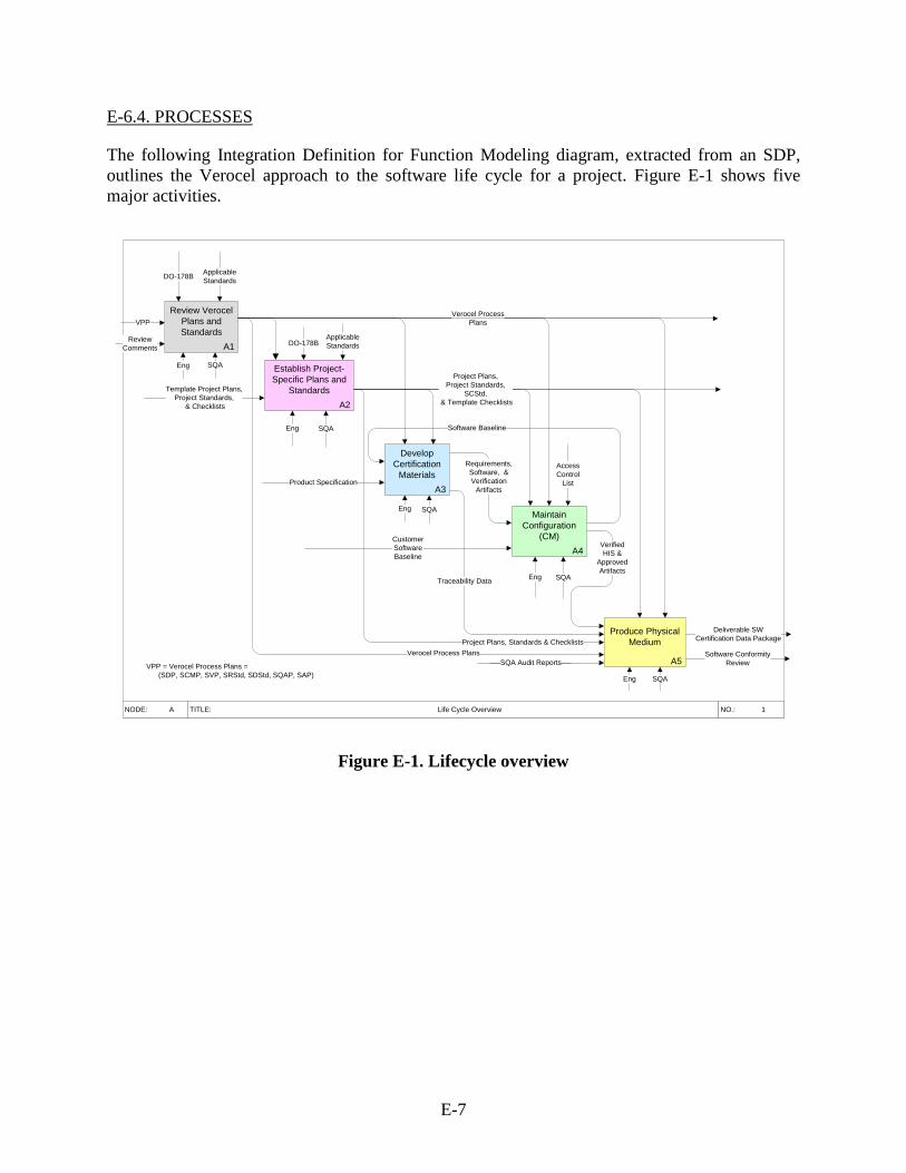
E-6.4. PROCESSES
The following Integration Definition for Function Modeling diagram, extracted from an SDP, outlines the Verocel approach to the software life cycle for a project. Figure E-1 shows five major activities.
A1
Review Verocel Plans and Standards
NODE: TITLE: NO.:Life Cycle Overview 1A
A2
Establish Project-Specific Plans and
Standards
DO-178B Applicable Standards
DO-178BApplicable Standards
Eng SQA
Eng SQA
Product SpecificationA3
Develop Certification
Materials
A4
Maintain Configuration
(CM)
Eng SQA
Access Control
List
Eng SQA
A5
Produce Physical Medium
Eng SQA
VPP
Verified HIS &
ApprovedArtifacts
CustomerSoftwareBaseline
Software ConformityReview
Deliverable SW Certification Data Package
Verocel ProcessPlans
Project Plans,Project Standards,
SCStd, & Template Checklists
Verocel Process Plans
Software Baseline
Template Project Plans,Project Standards,
& Checklists
Project Plans, Standards & Checklists
SQA Audit Reports
ReviewComments
VPP = Verocel Process Plans = (SDP, SCMP, SVP, SRStd, SDStd, SQAP, SAP)
Requirements,Software, &Verification
Artifacts
Traceability Data
Figure E-1. Lifecycle overview
E-7
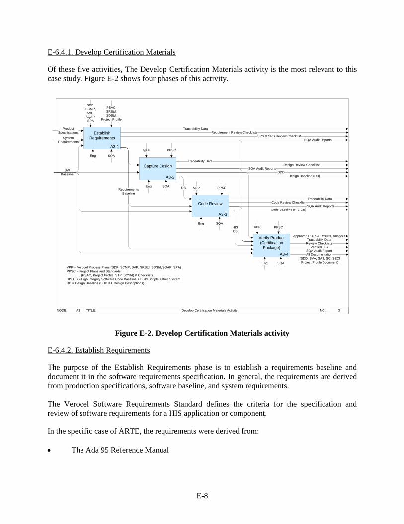
E-6.4.1. Develop Certification Materials
Of these five activities, The Develop Certification Materials activity is the most relevant to this case study. Figure E-2 shows four phases of this activity.
NODE: TITLE: NO.:Develop Certification Materials Activity 3A3
A3-1
Establish Requirements
ProductSpecifications
SDP,SCMP,SVP,
SQAP,SPA
VPP = Verocel Process Plans (SDP, SCMP, SVP, SRStd, SDStd, SQAP, SPA)PPSC = Project Plans and Standards
(PSAC, Project Profile, STP, SCStd) & ChecklistsHIS CB = High Integrity Software Code Baseline + Build Scripts + Built SystemDB = Design Baseline (SDD+LL Design Descriptions)
SQAEng
A3-2
Capture Design
PSAC,SRStd,SDStd,
Project Profile
VPP
SWBaseline
Requirement Review Checklists
SQAEng
PPSC
SQA Audit Reports
A3-3
Code Review
VPP PPSC
SQAEng
Code Review Checklist
Code Baseline (HIS CB)
A3-4
Verify Product (Certification
Package)
HIS CB
SQAEng
VPP PPSC
Approved RBTs & Results, AnalysisTraceability Data
Review ChecklistsVerified HIS
SQA Audit ReportAll Documentation
(SDD, SVA, SAS, SCI,SECIProject Profile Document)
SystemRequirements
Traceability Data
SRS & SRS Review ChecklistSQA Audit Reports
Traceability DataDesign Review Checklist
SDDDesign Baseline (DB)
Traceability Data
SQA Audit Reports
DBRequirementsBaseline
Figure E-2. Develop Certification Materials activity
E-6.4.2. Establish Requirements
The purpose of the Establish Requirements phase is to establish a requirements baseline and document it in the software requirements specification. In general, the requirements are derived from production specifications, software baseline, and system requirements. The Verocel Software Requirements Standard defines the criteria for the specification and review of software requirements for a HIS application or component. In the specific case of ARTE, the requirements were derived from: • The Ada 95 Reference Manual
E-8
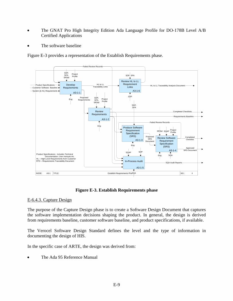
• The GNAT Pro High Integrity Edition Ada Language Profile for DO-178B Level A/B Certified Applications
• The software baseline
Figure E-3 provides a representation of the Establish Requirements phase.
NODE: TITLE: NO.:Establish Requirements Phase 4A3-1
A3-1-1
Develop Requirements
A3-1-3
Produce Software Requirement Specification
(SRS)
A3-1-2
Review Requirements
SDP,SPA,
SRStd
Product Specifications
System (& HL) Requirements
SDP,SPA,
SRStd
Eng
Eng
SQA
Eng
A3-1-4
Review Software Requirement Specification
(SRS)
Eng
SQAPSRStd
ProjectProfile
ProjectProfile
ProposedSRS
Document
Customer Software Baseline
CompletedChecklist
Approved SRS Document
A3-1-5
In-Process Audit
SQA
SQAP
SQA Audit Reports
SDPProduct Specifications - Includes Technical
Documentation, User manuals etc.HL – High-Level Requirements from CustomerRTD – Requirements Traceability Document
ProposedRequirements
Requirements Baseline
Completed Checklists
ProjectProfile
Failed Review Records
SDP,SPA
A3-1-6
Review HL to LL Requirement
LinksHL to LL
Traceability Links HL to LL Traceability Analysis Document
SDP
SDP, SPA
Failed Review Records
Figure E-3. Establish Requirements phase
E-6.4.3. Capture Design
The purpose of the Capture Design phase is to create a Software Design Document that captures the software implementation decisions shaping the product. In general, the design is derived from requirements baseline, customer software baseline, and product specifications, if available. The Verocel Software Design Standard defines the level and the type of information in documenting the design of HIS. In the specific case of ARTE, the design was derived from: • The Ada 95 Reference Manual
E-9
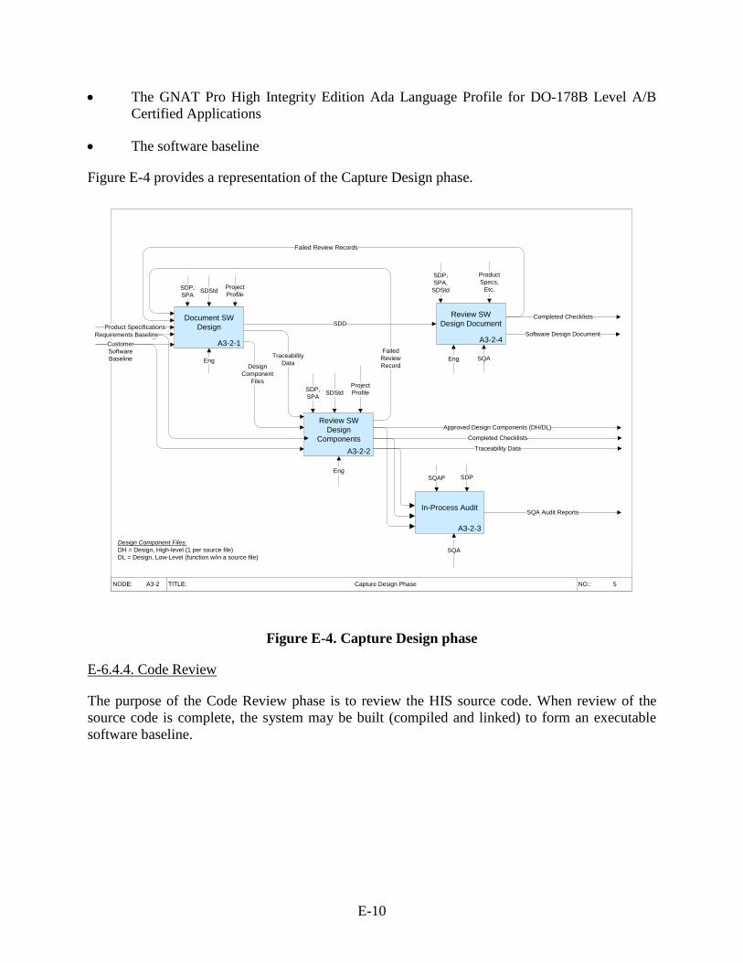
• The GNAT Pro High Integrity Edition Ada Language Profile for DO-178B Level A/B Certified Applications
• The software baseline
Figure E-4 provides a representation of the Capture Design phase.
NODE: TITLE: NO.:Capture Design Phase 5A3-2
A3-2-1
Document SW Design
A3-2-2
Review SW Design
Components
A3-2-4
Review SW Design Document
A3-2-3
In-Process Audit
Eng
Eng
Eng SQA
SQAP
SDP,SPA
SDStd
Design Component Files:DH = Design, High-level (1 per source file)DL = Design, Low-Level (function w/in a source file)
SDP,SPA SDStd
SDD
SDP,SPA,
SDStd
ProductSpecs,
Etc.
Completed Checklists
Approved Design Components (DH/DL)
Completed Checklists
Traceability Data
SQA
SQA Audit Reports
SDP
Project Profile
Project Profile
FailedReviewRecord
Failed Review Records
Software Design DocumentProduct Specifications
Design Component
Files
TraceabilityData
Requirements BaselineCustomerSoftwareBaseline
Figure E-4. Capture Design phase
E-6.4.4. Code Review
The purpose of the Code Review phase is to review the HIS source code. When review of the source code is complete, the system may be built (compiled and linked) to form an executable software baseline.
E-10
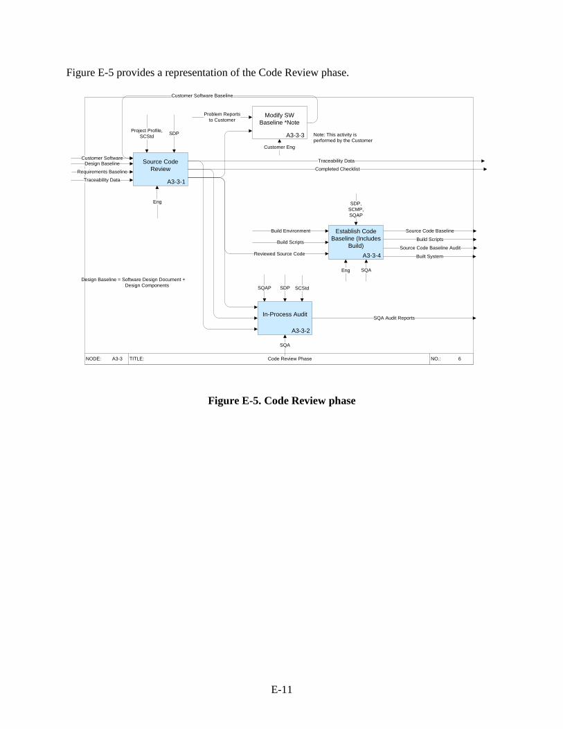
Figure E-5 provides a representation of the Code Review phase.
NODE: TITLE: NO.:Code Review Phase 6A3-3
A3-3-1
Source Code Review
Project Profile,SCStd
Customer SoftwareDesign Baseline
Eng
SDP
A3-3-4
Establish Code Baseline (Includes
Build)
A3-3-2
In-Process Audit
Completed Checklist
SQA
Eng SQA
SQAP
SQA Audit Reports
SDP,SCMP,SQAP
Source Code Baseline
Source Code Baseline Audit
Design Baseline = Software Design Document + Design Components SDP
A3-3-3
Modify SW Baseline *Note
Requirements Baseline
Traceability Data
Traceability Data
Customer Software Baseline
Customer Eng
Problem Reportsto Customer
Build Scripts
Reviewed Source Code
Build Scripts
Built System
Build Environment
SCStd
Note: This activity is performed by the Customer
Figure E-5. Code Review phase
E-11
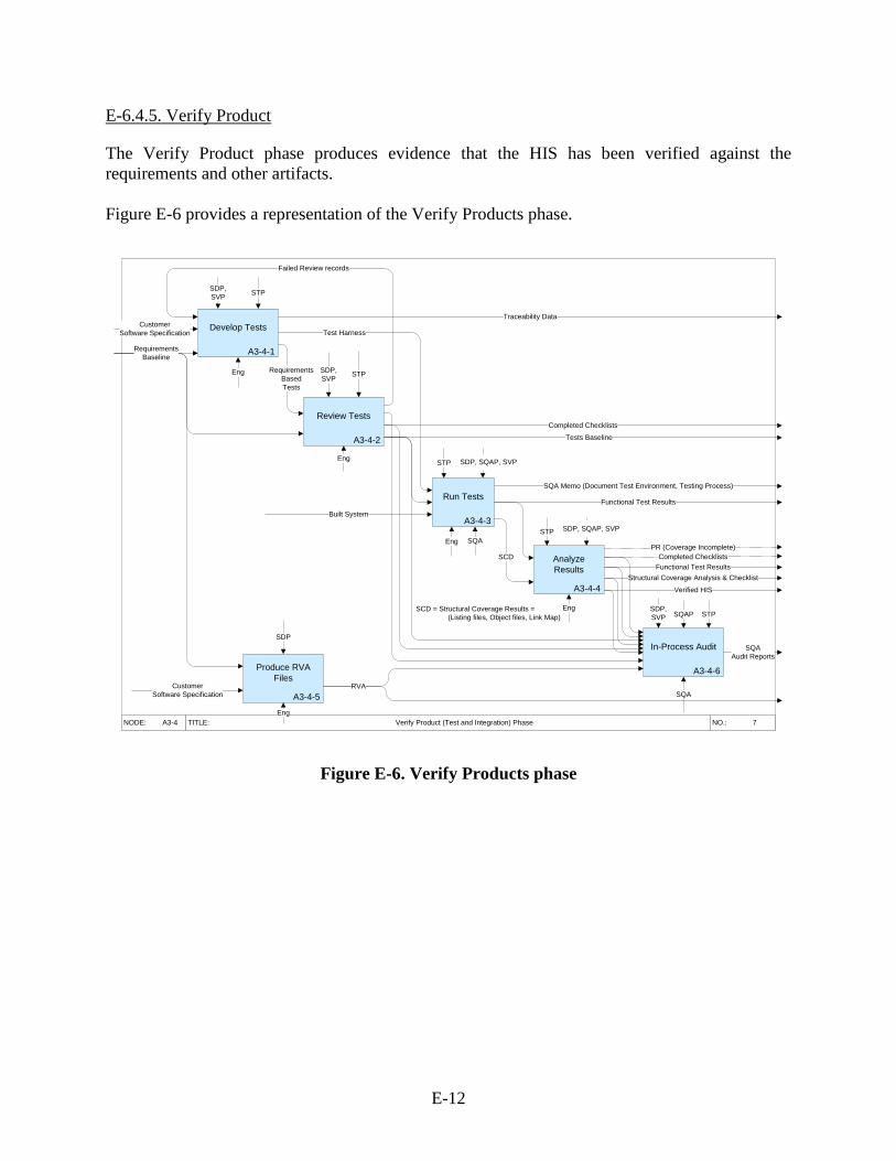
E-6.4.5. Verify Product
The Verify Product phase produces evidence that the HIS has been verified against the requirements and other artifacts. Figure E-6 provides a representation of the Verify Products phase.
NODE: TITLE: NO.:Verify Product (Test and Integration) Phase 7A3-4
A3-4-1
Develop Tests
A3-4-2
Review Tests
A3-4-3
Run Tests
A3-4-4
Analyze Results
A3-4-6
In-Process Audit
Eng
SDP,SVP STP
Eng
SDP,SVP STP
Traceability Data
Completed Checklists
Eng SQA
SCD = Structural Coverage Results = (Listing files, Object files, Link Map)
STP
STP
Eng
Built System
SQA Memo (Document Test Environment, Testing Process)
Functional Test Results
Verified HIS
SQA Audit Reports
SQAP
SQA
Structural Coverage Analysis & Checklist
RequirementsBasedTests
Test Harness
PR (Coverage Incomplete)
STPSDP,SVP
SCD
Tests Baseline
Functional Test Results
Failed Review records
A3-4-5
Produce RVA Files
CustomerSoftware Specification
CustomerSoftware Specification
SDP, SQAP, SVP
SDP, SQAP, SVP
RVA
RequirementsBaseline
Completed Checklists
Eng
SDP
Figure E-6. Verify Products phase
E-12
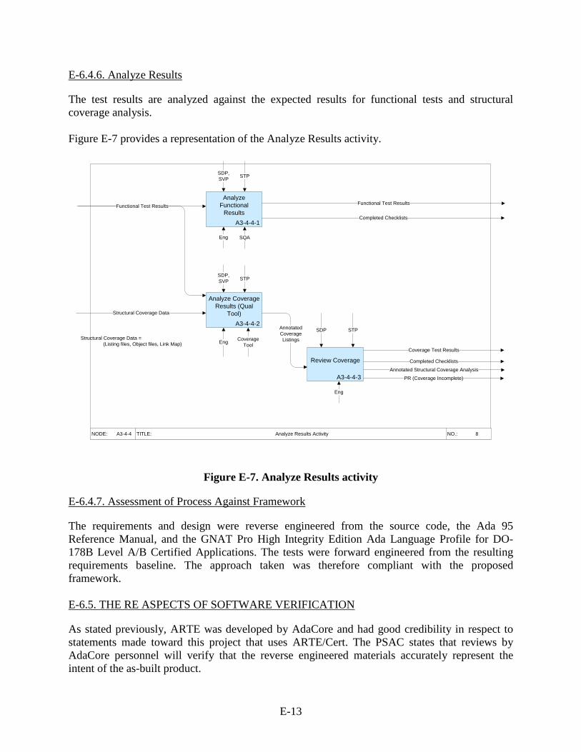
E-6.4.6. Analyze Results
The test results are analyzed against the expected results for functional tests and structural coverage analysis. Figure E-7 provides a representation of the Analyze Results activity.
NODE: TITLE: NO.:Analyze Results Activity 8A3-4-4
A3-4-4-1
Analyze Functional
Results
A3-4-4-3
Review Coverage
A3-4-4-2
Analyze Coverage Results (Qual
Tool)
SDP,SVP
Eng
CoverageTool
AnnotatedCoverageListings
Eng
SQA
Functional Test Results
Completed Checklists
Coverage Test Results
Completed Checklists
SDP,SVP
Functional Test Results
Eng
Structural Coverage Data
Annotated Structural Coverage Analysis
STP
STP
SDP STP
PR (Coverage Incomplete)
Structural Coverage Data = (Listing files, Object files, Link Map)
Figure E-7. Analyze Results activity
E-6.4.7. Assessment of Process Against Framework
The requirements and design were reverse engineered from the source code, the Ada 95 Reference Manual, and the GNAT Pro High Integrity Edition Ada Language Profile for DO-178B Level A/B Certified Applications. The tests were forward engineered from the resulting requirements baseline. The approach taken was therefore compliant with the proposed framework. E-6.5. THE RE ASPECTS OF SOFTWARE VERIFICATION
As stated previously, ARTE was developed by AdaCore and had good credibility in respect to statements made toward this project that uses ARTE/Cert. The PSAC states that reviews by AdaCore personnel will verify that the reverse engineered materials accurately represent the intent of the as-built product.
E-13
E-6.6. GENERIC RE SUBJECT MATTER EXPERT VERIFICATION PROCESS
Any issues raised by AdaCore were recorded as PRs by their subject matter experts (SMEs). It is recommended that the Verocel Plans and Standards should be updated to formalize the use of SMEs, rather than leave this to the project-specific PSAC. E-6.7. ACCEPTANCE CRITERIA
The ARTE requirements and design artifacts exhibit a satisfactory level of abstraction from the source code. The requirement review checklist appears to be based on the normal DO-178B [E-1] criteria (e.g., each requirement is accurate and unambiguous, and does not reflect the special needs of RE suggested by the proposed framework). It is recommended that the Verocel requirements review checklist be updated in accordance with the framework. E-6.8. RECOMMENDATIONS
The Certification Package was completed, assessed through four Stage of Involvement audits, approved by several DERs, and signed off by the DER of record. Analysis of the planning documents and standards show that while adequate procedures were used during the verification process, some elements were done as a good software engineering practice, although they were not formalized in the plans and standards. The following recommendations are made as a result of assessing the ARTE case study against the proposed framework: • The Verocel Software Requirements Standard should be updated to define how RE
techniques should be used, if appropriate. • The Verocel process plans should describe and formalize the use of SMEs. • The Verocel requirements review checklist should ensure that the LLRs show some level
of understanding of the intent of the source code and are not too close a match to the source code.
E.7. REFERENCES
E-1. RTCA/DO-178B, Software Considerations in Airborne System and Equipment Certification, December 1, 1992.
E-2. SR Std., Software Requirements Standard, Version 2.0. Verocel Company, 2009.
E-3. SR Std., Software Design Standard, Version 2.0. Verocel Company, 2009.
E-14
APPENDIX F—VALIDATION OF FRAMEWORK FOR AIRBORNE ELECTRONIC HARDWARE
F-1. VALIDATE FRAMEWORK
This project was controlled by the International Traffic in Arms Regulations. No details of the specific project, functionality, customer, and aircraft are disclosed using XXX that prevents precise identification of the equipment, but the approach to certification is analyzed as it pertains to reverse engineering (RE). The scope of this project was described in the XXX Plan for Hardware Aspects of Certification (PHAC) as follows: This document is the PHAC for the XXX of the Identified Aircraft. The XXX is comprised of a number of Interface Control Units (ICUs) that are interconnected using a communication network. Each ICU contains a number of devices arranged on circuit boards. Each board contains a microcontroller, memory, a commercial off-the-shelf device to control the lower levels of the communications protocol, and other devices developed specifically to support the ICU and XXX. These devices are interconnected using various information busses. The devices work at different speeds and have their own specific communication protocols. A programmable logic device (PLD) is used to manage the interconnections between the devices and connections to various discrete input/output pins. This PLD is a field programmable gate array that will be programmed specifically to support the design of the ICU target board. The PLD will be developed and verified to ensure that the target board supports the functional operations of the ICU and the XXX. This plan addresses the engineering and management processes and practices to be used during the development and verification of the PLD program. These processes and practices will result in life cycle data for the PLDs2 as a complete certification data package to support approval under the objectives of DO-254 [F-1] for Design Assurance Level B. This plan is modeled after the software certification guidelines of DO-178B [F-2] and complies with DO-254. It describes both the hardware development life cycle activities used by the customer in the development of the PLDs for the XXX and the verification activities performed by Verocel, Inc. on behalf of the customer.” This plan is intended for use by the certification authorities and their designees to allow a review of the intended development and verification processes, and the determination of the adequacy of the processes used.
2 Two separate PLDs were used on the platform: one implemented the high-speed bus, and the other implemented the A/D converters, discrete signals, and low speed busses.
F-1
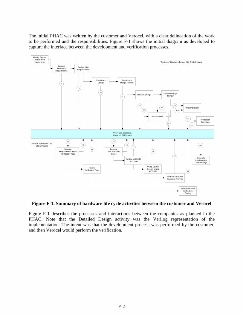
The initial PHAC was written by the customer and Verocel, with a clear delineation of the work to be performed and the responsibilities. Figure F-1 shows the initial diagram as developed to capture the interface between the development and verification processes.
Identify System and derived
requirements
Capture Hardware
Requirements
Production Transition
Implementation
Preliminary Design
Detailed Design
Develop Requirements-Based
Verification Tests
Produce Structural Coverage Analysis
Verify Device Design using
MODSIM
Develop MODSIM Test
Cases
Review Verification Tests
‘Customer’ Hardware Design Life Cycle Phases
Verocel Verification Life Clcye Phases
VeroTrace Database,Common CM System
Review HW Requirements
Preliminary Design Review
Detailed Design Review
Procurement
P1
P9
P10
P8
P7P6
P5
P4
P3
P2
Generate Certifiacation Data Package
Software Based Verification
Testing
V5V1
V9
V8
V4
P12
P11
Review MODSIM Test Cases
V10V7
V3
V2 V6
Figure F-1. Summary of hardware life cycle activities between the customer and Verocel
Figure F-1 describes the processes and interactions between the companies as planned in the PHAC. Note that the Detailed Design activity was the Verilog representation of the implementation. The intent was that the development process was performed by the customer, and then Verocel would perform the verification.
F-2
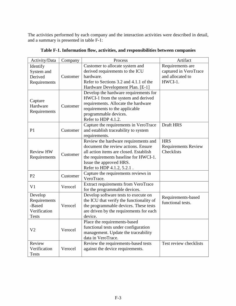
The activities performed by each company and the interaction activities were described in detail, and a summary is presented in table F-1:
Table F-1. Information flow, activities, and responsibilities between companies
Activity/Data Company Process Artifact Identify System and Derived Requirements
Customer
Customer to allocate system and derived requirements to the ICU hardware. Refer to Sections 3.2 and 4.1.1 of the Hardware Development Plan. [E-1]
Requirements are captured in VeroTrace and allocated to HWCI-1.
Capture Hardware Requirements
Customer
Develop the hardware requirements for HWCI-1 from the system and derived requirements. Allocate the hardware requirements to the applicable programmable devices. Refer to HDP 4.1.2.
P1 Customer Capture the requirements in VeroTrace and establish traceability to system requirements.
Draft HRS
Review HW Requirements Customer
Review the hardware requirements and document the review actions. Ensure all action items are closed. Establish the requirements baseline for HWCI-1. Issue the approved HRS. Refer to HDP 4.1.2, 5.2.1 .
HRS Requirements Review Checklists
P2 Customer Capture the requirements reviews in VeroTrace.
V1 Verocel Extract requirements from VeroTrace for the programmable devices.
Develop Requirements-Based Verification Tests
Verocel
Develop software tests to execute on the ICU that verify the functionality of the programmable devices. These tests are driven by the requirements for each device.
Requirements-based functional tests.
V2 Verocel
Place the requirements-based functional tests under configuration management. Update the traceability data in VeroTrace.
Review Verification Tests
Verocel Review the requirements-based tests against the device requirements.
Test review checklists
F-3
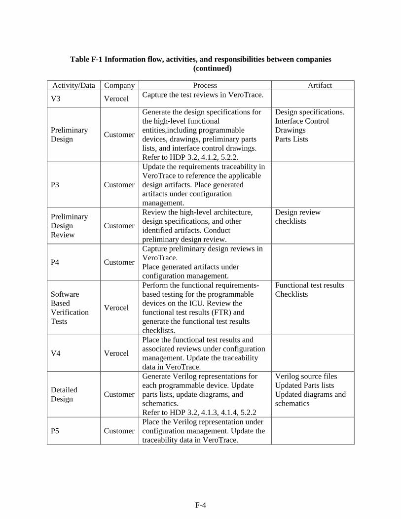
Table F-1 Information flow, activities, and responsibilities between companies (continued)
Activity/Data Company Process Artifact
V3 Verocel Capture the test reviews in VeroTrace.
Preliminary Design Customer
Generate the design specifications for the high-level functional entities,including programmable devices, drawings, preliminary parts lists, and interface control drawings. Refer to HDP 3.2, 4.1.2, 5.2.2.
Design specifications. Interface Control Drawings Parts Lists
P3 Customer
Update the requirements traceability in VeroTrace to reference the applicable design artifacts. Place generated artifacts under configuration management.
Preliminary Design Review
Customer
Review the high-level architecture, design specifications, and other identified artifacts. Conduct preliminary design review.
Design review checklists
P4 Customer
Capture preliminary design reviews in VeroTrace. Place generated artifacts under configuration management.
Software Based Verification Tests
Verocel
Perform the functional requirements-based testing for the programmable devices on the ICU. Review the functional test results (FTR) and generate the functional test results checklists.
Functional test results Checklists
V4 Verocel
Place the functional test results and associated reviews under configuration management. Update the traceability data in VeroTrace.
Detailed Design Customer
Generate Verilog representations for each programmable device. Update parts lists, update diagrams, and schematics. Refer to HDP 3.2, 4.1.3, 4.1.4, 5.2.2
Verilog source files Updated Parts lists Updated diagrams and schematics
P5 Customer Place the Verilog representation under configuration management. Update the traceability data in VeroTrace.
F-4
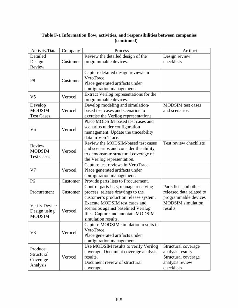
Table F-1 Information flow, activities, and responsibilities between companies (continued)
Activity/Data Company Process Artifact Detailed Design Review
Customer Review the detailed design of the programmable devices.
Design review checklists
P8 Customer
Capture detailed design reviews in VeroTrace. Place generated artifacts under configuration management.
V5 Verocel Extract Verilog representations for the programmable devices.
Develop MODSIM Test Cases
Verocel Develop modeling and simulation-based test cases and scenarios to exercise the Verilog representations.
MODSIM test cases and scenarios
V6 Verocel
Place MODSIM-based test cases and scenarios under configuration management. Update the traceability data in VeroTrace.
Review MODSIM Test Cases
Verocel
Review the MODSIM-based test cases and scenarios and consider the ability to demonstrate structural coverage of the Verilog representation.
Test review checklists
V7 Verocel Capture test reviews in VeroTrace. Place generated artifacts under configuration management.
P6 Customer Provide parts lists to Procurement.
Procurement Customer Control parts lists, manage receiving process, release drawings to the customer’s production release system.
Parts lists and other released data related to programmable devices
Verify Device Design using MODSIM
Verocel
Execute MODSIM test cases and scenarios against baselined Verilog files. Capture and annotate MODSIM simulation results.
MODSIM simulation results
V8 Verocel
Capture MODSIM simulation results in VeroTrace. Place generated artifacts under configuration management.
Produce Structural Coverage Analysis
Verocel
Use MODSIM results to verify Verilog coverage. Document coverage analysis results. Document review of structural coverage.
Structural coverage analysis results Structural coverage analysis review checklists
F-5
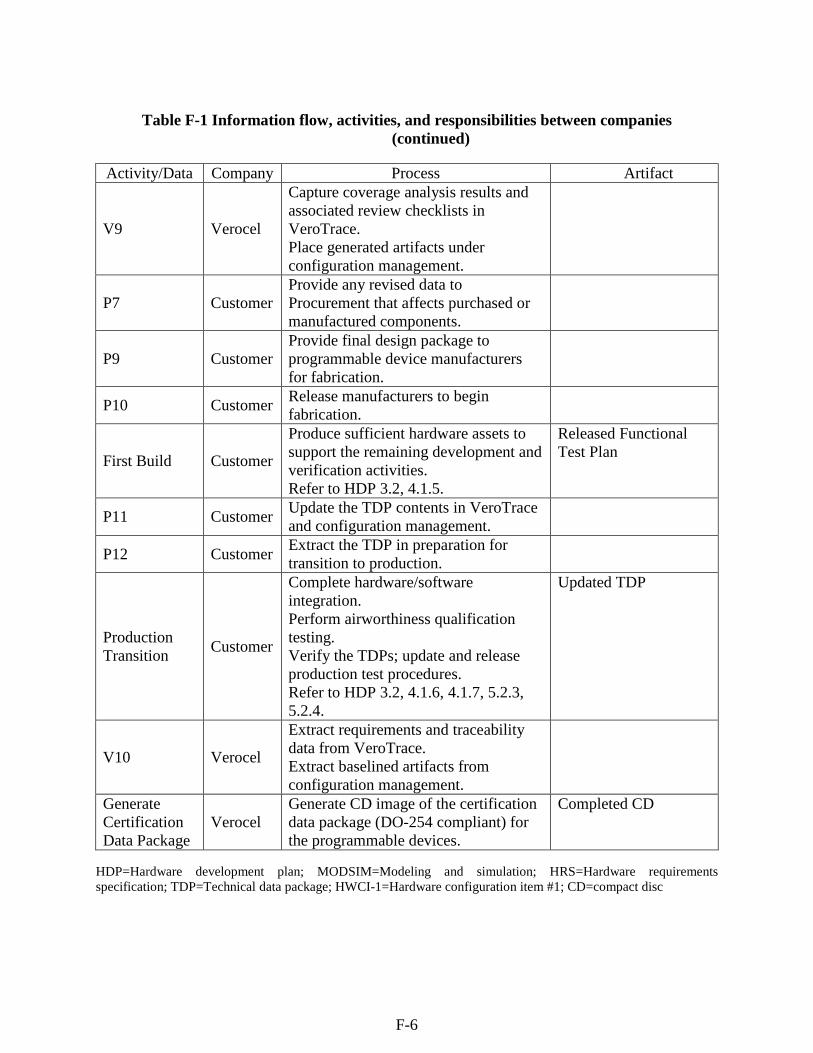
Table F-1 Information flow, activities, and responsibilities between companies (continued)
Activity/Data Company Process Artifact
V9 Verocel
Capture coverage analysis results and associated review checklists in VeroTrace. Place generated artifacts under configuration management.
P7 Customer Provide any revised data to Procurement that affects purchased or manufactured components.
P9 Customer Provide final design package to programmable device manufacturers for fabrication.
P10 Customer Release manufacturers to begin fabrication.
First Build Customer
Produce sufficient hardware assets to support the remaining development and verification activities. Refer to HDP 3.2, 4.1.5.
Released Functional Test Plan
P11 Customer Update the TDP contents in VeroTrace and configuration management.
P12 Customer Extract the TDP in preparation for transition to production.
Production Transition Customer
Complete hardware/software integration. Perform airworthiness qualification testing. Verify the TDPs; update and release production test procedures. Refer to HDP 3.2, 4.1.6, 4.1.7, 5.2.3, 5.2.4.
Updated TDP
V10 Verocel
Extract requirements and traceability data from VeroTrace. Extract baselined artifacts from configuration management.
Generate Certification Data Package
Verocel Generate CD image of the certification data package (DO-254 compliant) for the programmable devices.
Completed CD
HDP=Hardware development plan; MODSIM=Modeling and simulation; HRS=Hardware requirements specification; TDP=Technical data package; HWCI-1=Hardware configuration item #1; CD=compact disc
F-6
The system requirements, high-level requirements (HLRs), and preliminary design were developed and reviewed by the customer for credit. The expectation was that the HLRs and preliminary design would provide the requirements that form the basis for the verification work performed at Verocel. As the project progressed and the HLRs and code were delivered, initial review revealed that the requirements were inadequate. At the customer’s direction, Verocel was given the responsibility for the development of low-level requirements (LLRs). The project became an RE certification effort. HLRs, preliminary design, and Verilog code were imported into the VeroTrace database and Verocel configuration management system. Verocel obtained detailed specifications of all devices that were being interconnected (e.g., analog/digital (A/D) converters, serial communication devices, etc.). These specifications provided connection details as well as the communication protocols. RE of LLRs from the available information and Verilog code was performed using the processes typically used for software. The code was reviewed informally, LLRs were written by Verocel engineers, and traceability was added as the information was placed into VeroTrace. The LLRs were then reviewed against the HLRs, interface specifications, and preliminary design, which was treated as a high-level design. This review was performed both at Verocel and by subject matter experts (SMEs) at the customer site. LLR-based tests were written in Verilog and executed on a simulator. A test-scripting mechanism was written to ensure that all of the Verilog tests could be run and results captured in a single test run. The same testing script and tests were then used to run the tests in coverage mode. Coverage metrics were captured along with the test results. This process followed the Verocel company-wide verification plans used for software, but adaptations were made as necessary for the Verilog simulation approach used for tests. The customer retained responsibility for integration and system tests. Verocel was not involved in those processes. The final Hardware Accomplishment Summary (HAS) was written by the customer using information and referencing life cycle data provided by Verocel. The life cycle data was produced using the Verocel Digital Versatile Disc-Read Only Memory (DVD-ROM) process where all of the life cycle data is extracted from configuration management and transferred to a DVD-ROM. Additional traceability files are loaded, which provide hyperlinked traceability between all artifacts as required by DO-254. A standard browser may then be used to navigate between all life cycle artifacts. In addition, traceability information is extracted to tables that are stored on the DVD-ROM to allow information to be easily searched, sorted, and analyzed.
F-7
F-2. THE RE EXPERIENCE
The PHAC was not originally written with RE in mind. The intent was to follow a waterfall development process, followed by a waterfall verification process. The customer decided that a working prototype was more important, as there were many other applications and systems activities that were dependent on having a functional platform. The platform was developed before the rest of the system by developing the platform components, programming the PLDs, and integrating the components. The following RE approach was then applied to the platform software and PLD devices: • The PHAC was not changed to describe the RE approach adopted part way through the
program; however, the Verocel processes that address RE were called out, and the change was described in the Electronic HAS.
• Access to domain experts was provided and was very useful at the start of the project. However, part way through, the expert left and was replaced by someone who was not as familiar with the system. By this time, Verocel had mastered much of the intent of the platform and was able to suggest changes to the platform using their expertise. System level experts were available, but they were not platform experts, and did not fully understand the nuances of some platform behaviors.
• The verification reviewers were much more risk averse than the original developers. While the system worked well, the verification engineers were much more concerned with the timing margins programmed into the PLD design. If a pair of signals was expected in sequence, then the code was written to respond correctly if a specific signal appeared before the other (e.g., data, followed by data ready). However, if they arrived at the same time, the processing was performed as if they were in very close sequence. Because the signal times could deviate slightly based on temperature and component tolerances, the review engineers requested a predefined time margin, which would accommodate potential variations and improve reliability. As the system worked well in the engineering laboratory, there was some reluctance to make any changes. Verocel had to insist, refusing to support designated engineering representative audits unless the problems were addressed.
F-3. ASSESSMENT OF THE RE FRAMEWORK FOR AIRBORNE ELECTRONIC HARDWARE
RE was not planned initially, and the PHAC accurately reflected the intent. As RE development and verification were adopted, it was decided to document these deviations in the final HAS. Access to SMEs was good at the start of the project, but unplanned personnel changes at the customer site part way through the project meant that access to SMEs became poor. Access to the overall system experts was available throughout the project, but specific expertise on platform and board level design became scarce. Fortunately, this was mitigated by the verification engineers becoming experts in the requirements and design of the platform.
F-8
The verification materials were produced and traceability was established for the devices. The consistency between all life cycle artifacts was established with independence, although the project had a Design Assurance Level of B. The Verocel company process plans support an RE verification approach. These plans were referenced in the PHAC for the project. RE was followed, although the PHAC did not describe an RE approach. The HAS did make the appropriate adjustments. Following the recommendations of this report, it would have been better to make the use of RE much more explicit by changing the PHAC. The following recommendations are made as a result of assessing the airborne electronic hardware case study against the proposed framework: • The Verocel Software Requirements Standard should be updated to define how RE
techniques should be used, when appropriate.
• The Verocel process plans should describe and formalize the use of SMEs.
• The Verocel requirements review checklist should ensure that the LLRs show some level of understanding of the intent of the Verilog code and are not too close a match to the code.
• The Verocel document review checklist used to review the PHAC documents should be updated to ensure that RE is addressed, if used.
F-4. REFERENCES
F-1. RTCA/DO-254, “Design Assurance Guidance for Airborne Electronic Hardware,” April 19, 2000.
F-2. RTCA/DO-178B, “Software Considerations in Airborne System and Equipment
Certification,” December 1, 1992.
F-9


![CHARLES KILGORE and HIRAM KILGORE [BROTHERS]€¦ · Five brothers who were great, great grandsons of Lord Douglas Kilgore came to America in 1763 from Scotland. Charles Kilgore,](https://img.pdfslide.us/doc/110x75/5fc655f49e1a8763c4599104/charles-kilgore-and-hiram-kilgore-brothers-five-brothers-who-were-great-great.jpg)