Embed Size (px)
Citation preview
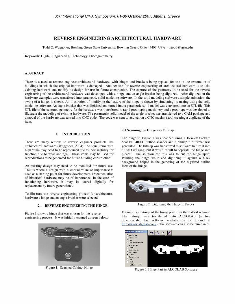
REVERSE ENGINEERING ARCHITECTURAL HARDWARE
Todd C. Waggoner, Bowling Green State University, Bowling Green, Ohio 43403, USA – [email protected]
Keywords: Digital, Engineering, Technology, Photogrammetry
ABSTRACT
There is a need to reverse engineer architectural hardware, with hinges and brackets being typical, for use in the restoration of
buildings in which the original hardware is damaged. Another use for reverse engineering of architectural hardware is to take
existing hardware and modify its design for use in future construction. The capture of the geometry to be used for the reverse
engineering of the architectural hardware was developed with a hinge and an angle bracket being digitized. After digitization the
hardware examples were transferred into parametric solid modeling software. In the solid modeling software a simple animation, the
swing of a hinge, is shown. An illustration of modifying the texture of the hinge is shown by simulating its rusting using the solid
modeling software. An angle bracket that was digitized and turned into a parametric solid model was converted into an STL file. This
STL file of the captured geometry for the hardware was transferred to rapid prototyping machinery and a prototype was developed to
illustrate the modeling of existing hardware. The parametric solid model of the angle bracket was transferred to a CAM package and
a model of the hardware was turned into CNC code. The code was sent to and cut on a CNC machine tool creating a duplicate of the
item.
1. INTRODUCTION
There are many reasons to reverse engineer products like
architectural hardware (Waggoner, 2004). Antique items with
high value may need to be reproduced due to their inability for
function due to wear and age. These items may be used for
reproductions to be generated for future building construction.
An existing design may need to be modified for future use.
This is where a design with historical value or importance is
used as a starting point for future development. Documentation
of historical hardware may be of importance. In the case of
functioning hardware, it may be stored digitally for
replacement by future generations.
To illustrate the reverse engineering process for architectural
hardware a hinge and an angle bracket were selected.
2. REVERSE ENGINEERING THE HINGE
Figure 1 shows a hinge that was chosen for the reverse
engineering process. It was initially scanned as seen below:
Figure 1. Scanned Cabinet Hinge
2.1 Scanning the Hinge as a Bitmap
The hinge in Figure 1 was scanned using a Hewlett Packard
ScanJet 3400 C flatbed scanner and a bitmap file format was
generated. The bitmap was transferred to software to turn it into
a CAD drawing, but it was difficult to separate the hinge into
pieces. The solution for this was to cut the hinge apart.
Painting the hinge white and digitizing it against a black
background helped in the gathering of the digitized outline
form of the image.
Figure 2. Digitizing the Hinge in Pieces
Figure 2 is a bitmap of the hinge part from the flatbed scanner.
The bitmap was transferred into ALGOLAB (a free
downloadable trial software available on the Internet at
http://www.algolab.com/). The software can also be purchased.
Figure 3. Hinge Part in ALGOLAB Software
XXI International CIPA Symposium, 01-06 October 2007, Athens, Greece
2.2 Converting the Bitmap to a DXF File Format
Figure 4 shows a CAD drawing generated in the ALGOLAB
software of the scrolled portion of the hinge.
Figure 4. Outline in CAD Drawing Created in ALGOLAB
Some editing of the drawing was done. The DXF format
drawing was opened in SolidWorks DWG editor and saved as a
DWG file for transferal into SolidWorks 2006 (Sp 4.1). In
Figure 5 the drawing has been opened in SolidWorks and the
extrusion process has been started.
2.3 Manipulating the Digitized Model in the Solid Modeling
Software
Figure 5. Extruding Pieces of the Hinge
Figure 6. Extruded Hinge Piece
After the hinge had been extruded, some of the internal details
needed to be created in the solid modeling program. The use of
a 3D scanner and the generation of a point cloud instead of an
outline could be used to eliminate the need for the
constructions in the solid modeler. The goal of this research
was to use inexpensive means to duplicate the hinge.
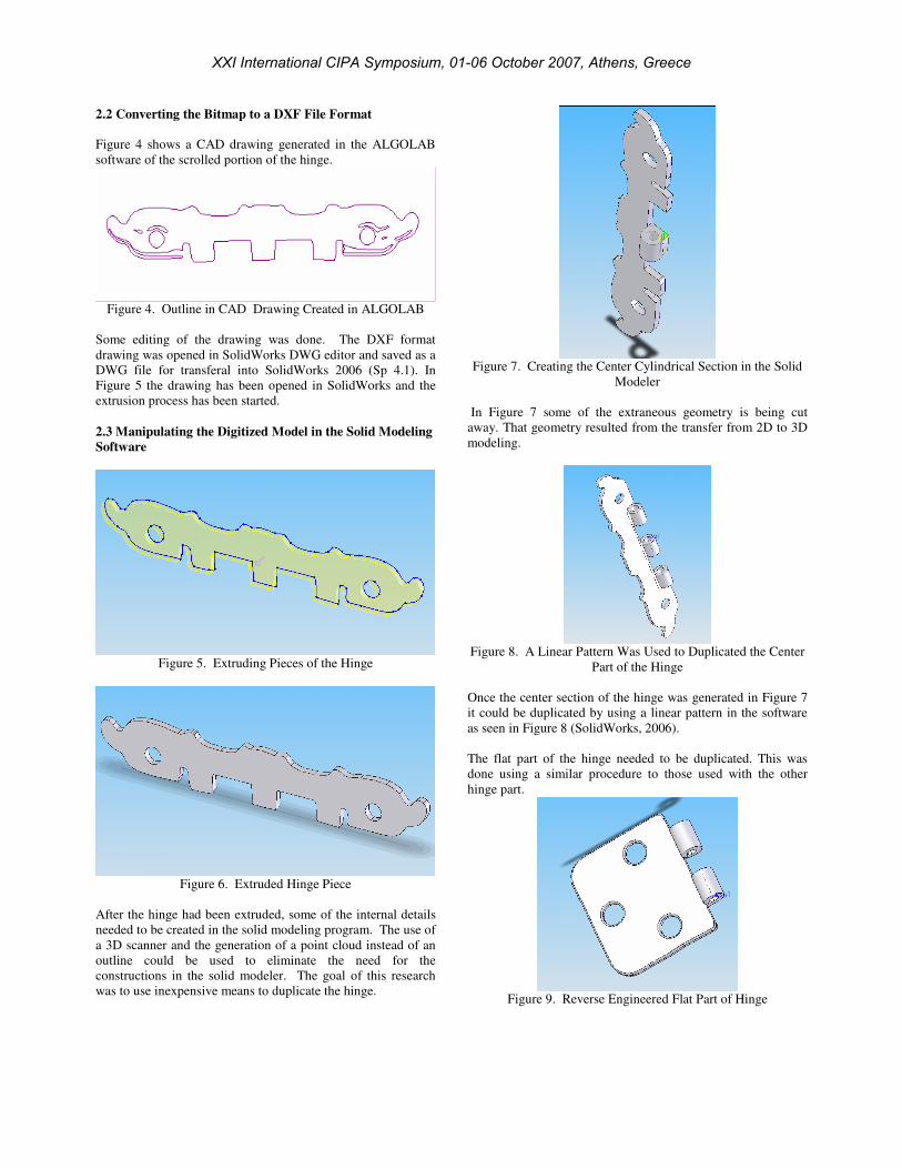
Figure 7. Creating the Center Cylindrical Section in the Solid
Modeler
In Figure 7 some of the extraneous geometry is being cut
away. That geometry resulted from the transfer from 2D to 3D
modeling.
Figure 8. A Linear Pattern Was Used to Duplicated the Center
Part of the Hinge
Once the center section of the hinge was generated in Figure 7
it could be duplicated by using a linear pattern in the software
as seen in Figure 8 (SolidWorks, 2006).
The flat part of the hinge needed to be duplicated. This was
done using a similar procedure to those used with the other
hinge part.
Figure 9. Reverse Engineered Flat Part of Hinge
XXI International CIPA Symposium, 01-06 October 2007, Athens, Greece
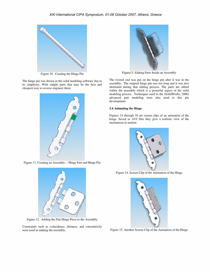
Figure 10. Creating the Hinge Pin
The hinge pin was drawn in the solid modeling software due to
its simplicity. With simple parts that may be the best and
cheapest way to reverse engineer them.
Figure 11. Creating an Assembly -- Hinge Part and Hinge Pin
Figure 12. Adding the Flat Hinge Piece to the Assembly
Constraints such as coincidence, distance, and concentricity
were used in making the assembly.
Figure13. Editing Parts Inside an Assembly
The riveted end was put on the hinge pin after it was in the
assembly. The original hinge pin was too long and it was also
shortened during that editing process. The parts are edited
within the assembly which is a powerful aspect of the solid
modeling process. Techniques used in the (SolidWorks, 2006)
advanced part modeling were also used in this pin
development.
2.4 Animating the Hinge
Figures 14 through 16 are screen clips of an animation of the
hinge. Saved as AVI files they give a realistic view of the
mechanism in motion.
Figure 14. Screen Clip of the Animation of the Hinge
Figure 15. Another Screen Clip of the Animation of the Hinge
XXI International CIPA Symposium, 01-06 October 2007, Athens, Greece
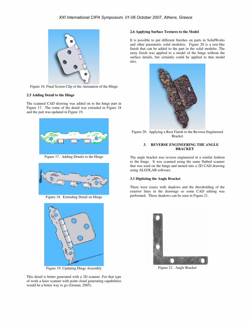
Figure 16. Final Screen Clip of the Animation of the Hinge
2.5 Adding Detail to the Hinge
The scanned CAD drawing was added on to the hinge part in
Figure 17. The some of the detail was extruded in Figure 18
and the part was updated in Figure 19.
Figure 17. Adding Details to the Hinge
Figure 18. Extruding Detail on Hinge
Figure 19. Updating Hinge Assembly
This detail is better generated with a 3D scanner. For that type
of work a laser scanner with point cloud generating capabilities
would be a better way to go (Grimm, 2005).
2.6 Applying Surface Textures to the Model
It is possible to put different finishes on parts in SolidWorks
and other parametric solid modelers. Figure 20 is a rust-like
finish that can be added to the part in the solid modeler. The
rusty finish was applied to a model of the hinge without the
surface details, but certainly could be applied to that model
also.
Figure 20. Applying a Rust Finish to the Reverse Engineered
Bracket
3. REVERSE ENGINEERING THE ANGLE
BRACKET
The angle bracket was reverse engineered in a similar fashion
to the hinge. It was scanned using the same flatbed scanner
that was used on the hinge and turned into a 2D CAD drawing
using ALGOLAB software.
3.1 Digitizing the Angle Bracket
There were issues with shadows and the thresholding of the
exterior lines in the drawings so some CAD editing was
performed. These shadows can be seen in Figure 21.
Figure 21. Angle Bracket
XXI International CIPA Symposium, 01-06 October 2007, Athens, Greece
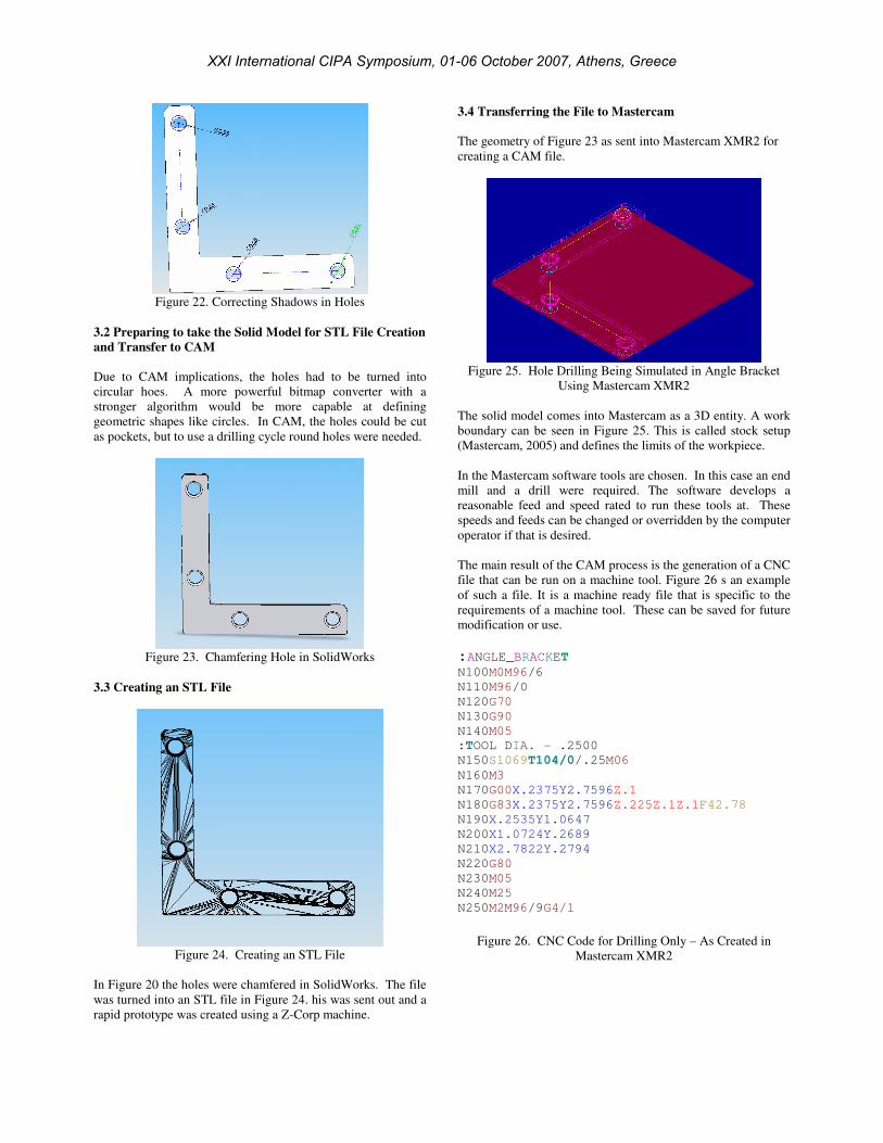
Figure 22. Correcting Shadows in Holes
3.2 Preparing to take the Solid Model for STL File Creation
and Transfer to CAM
Due to CAM implications, the holes had to be turned into
circular hoes. A more powerful bitmap converter with a
stronger algorithm would be more capable at defining
geometric shapes like circles. In CAM, the holes could be cut
as pockets, but to use a drilling cycle round holes were needed.
Figure 23. Chamfering Hole in SolidWorks
3.3 Creating an STL File
Figure 24. Creating an STL File
In Figure 20 the holes were chamfered in SolidWorks. The file
was turned into an STL file in Figure 24. his was sent out and a
rapid prototype was created using a Z-Corp machine.
3.4 Transferring the File to Mastercam
The geometry of Figure 23 as sent into Mastercam XMR2 for
creating a CAM file.
Figure 25. Hole Drilling Being Simulated in Angle Bracket
Using Mastercam XMR2
The solid model comes into Mastercam as a 3D entity. A work
boundary can be seen in Figure 25. This is called stock setup
(Mastercam, 2005) and defines the limits of the workpiece.
In the Mastercam software tools are chosen. In this case an end
mill and a drill were required. The software develops a
reasonable feed and speed rated to run these tools at. These
speeds and feeds can be changed or overridden by the computer
operator if that is desired.
The main result of the CAM process is the generation of a CNC
file that can be run on a machine tool. Figure 26 s an example
of such a file. It is a machine ready file that is specific to the
requirements of a machine tool. These can be saved for future
modification or use.
:ANGLE_BRACKET N100M0M96/6
N110M96/0
N120G70
N130G90
N140M05
:TOOL DIA. - .2500
N150S1069T104/0/.25M06
N160M3
N170G00X.2375Y2.7596Z.1
N180G83X.2375Y2.7596Z.225Z.1Z.1F42.78
N190X.2535Y1.0647
N200X1.0724Y.2689
N210X2.7822Y.2794
N220G80
N230M05
N240M25
N250M2M96/9G4/1
Figure 26. CNC Code for Drilling Only – As Created in
Mastercam XMR2
XXI International CIPA Symposium, 01-06 October 2007, Athens, Greece
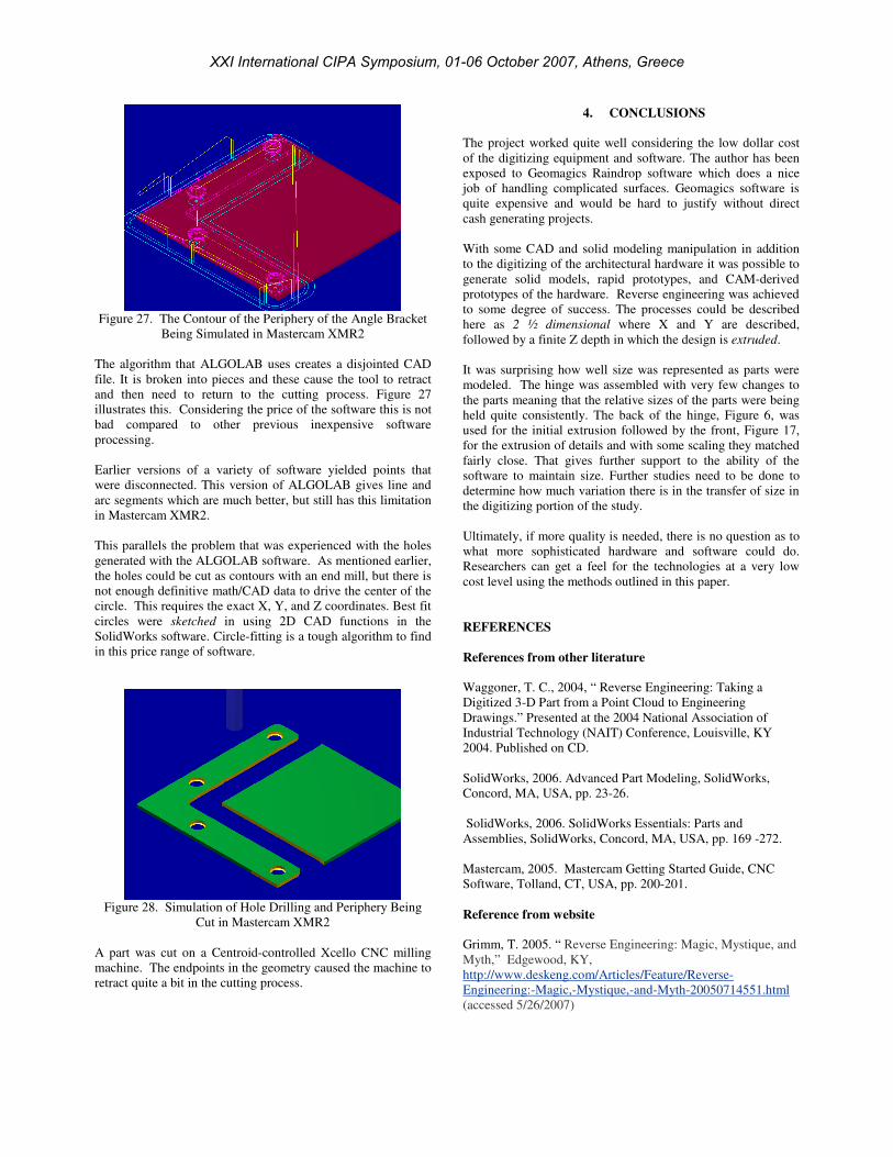
Figure 27. The Contour of the Periphery of the Angle Bracket
Being Simulated in Mastercam XMR2
The algorithm that ALGOLAB uses creates a disjointed CAD
file. It is broken into pieces and these cause the tool to retract
and then need to return to the cutting process. Figure 27
illustrates this. Considering the price of the software this is not
bad compared to other previous inexpensive software
processing.
Earlier versions of a variety of software yielded points that
were disconnected. This version of ALGOLAB gives line and
arc segments which are much better, but still has this limitation
in Mastercam XMR2.
This parallels the problem that was experienced with the holes
generated with the ALGOLAB software. As mentioned earlier,
the holes could be cut as contours with an end mill, but there is
not enough definitive math/CAD data to drive the center of the
circle. This requires the exact X, Y, and Z coordinates. Best fit
circles were sketched in using 2D CAD functions in the
SolidWorks software. Circle-fitting is a tough algorithm to find
in this price range of software.
Figure 28. Simulation of Hole Drilling and Periphery Being
Cut in Mastercam XMR2
A part was cut on a Centroid-controlled Xcello CNC milling
machine. The endpoints in the geometry caused the machine to
retract quite a bit in the cutting process.
4. CONCLUSIONS
The project worked quite well considering the low dollar cost
of the digitizing equipment and software. The author has been
exposed to Geomagics Raindrop software which does a nice
job of handling complicated surfaces. Geomagics software is
quite expensive and would be hard to justify without direct
cash generating projects.
With some CAD and solid modeling manipulation in addition
to the digitizing of the architectural hardware it was possible to
generate solid models, rapid prototypes, and CAM-derived
prototypes of the hardware. Reverse engineering was achieved
to some degree of success. The processes could be described
here as 2 ½ dimensional where X and Y are described,
followed by a finite Z depth in which the design is extruded.
It was surprising how well size was represented as parts were
modeled. The hinge was assembled with very few changes to
the parts meaning that the relative sizes of the parts were being
held quite consistently. The back of the hinge, Figure 6, was
used for the initial extrusion followed by the front, Figure 17,
for the extrusion of details and with some scaling they matched
fairly close. That gives further support to the ability of the
software to maintain size. Further studies need to be done to
determine how much variation there is in the transfer of size in
the digitizing portion of the study.
Ultimately, if more quality is needed, there is no question as to
what more sophisticated hardware and software could do.
Researchers can get a feel for the technologies at a very low
cost level using the methods outlined in this paper.
REFERENCES
References from other literature
Waggoner, T. C., 2004, “ Reverse Engineering: Taking a
Digitized 3-D Part from a Point Cloud to Engineering
Drawings.” Presented at the 2004 National Association of
Industrial Technology (NAIT) Conference, Louisville, KY
2004. Published on CD.
SolidWorks, 2006. Advanced Part Modeling, SolidWorks,
Concord, MA, USA, pp. 23-26.
SolidWorks, 2006. SolidWorks Essentials: Parts and
Assemblies, SolidWorks, Concord, MA, USA, pp. 169 -272.
Mastercam, 2005. Mastercam Getting Started Guide, CNC
Software, Tolland, CT, USA, pp. 200-201.
Reference from website
Grimm, T. 2005. “ Reverse Engineering: Magic, Mystique, and
Myth,” Edgewood, KY,
http://www.deskeng.com/Articles/Feature/Reverse-
Engineering:-Magic,-Mystique,-and-Myth-20050714551.html
(accessed 5/26/2007)
XXI International CIPA Symposium, 01-06 October 2007, Athens, Greece