Embed Size (px)
Citation preview

SEASI 2017 CONFERENCE , 22-25 MAY 2017, SINGAPORE
Page 1 of 9
Revamping of EAF Dedusting Plant to
Optimize Off-Gas & Dust Control System
in PT Krakatau Steel (Persero), Tbk.
Rio Arosyid Putra1
Syafiq Hadi2
1. Senior Specialist of Techno-economy, Project Control of EAF Dedusting Plant Revamping. Division of
Technology & Energy Development. PT Krakatau Steel (Persero) Tbk. Cigading Plant Site, Cilegon – 42435,
Banten Province, Indonesia. (E-mail: [email protected])
2. Superintendent Melting-2 of Slab Steel Plant, Head of Commissioning & Performance Test of EAF Dedusting
Plant Revamping. Division of Slab Steel Plant. PT Krakatau Steel (Persero) Tbk. Cigading Plant Site, Cilegon
– 42435, Banten Province, Indonesia. (E-mail: [email protected])
ABSTRACT
PT Krakatau Steel (Persero) Tbk is currently building Blast Furnace Plant which produces
hot metal to be fed into Electric Arc Furnace (EAF) and it will reduce the composition of solid
material. The use of hot metal will impact to the operation of Dedusting Plant since it was
designed only to process EAF off-gas (sponge iron based operation). This paper describes
about revamping project of EAF Dedusting Plant which was finished under self-management
of PT Krakatau Steel (Persero) Tbk including basic and detail design, manufacturing,
procurement, installation and commissioning. The water cooled duct was reconditioned and
extended to increase Dedusting Plant capability to absorb heat from larger volume of off-gas.
In addition, Drop Out Box (DOB) was also installed to isolate larger duct particles and therefore
it will minimize dust settlement in the duct. The results of this project were not only successful
to modify optimized off-gas & dust control, but also significantly reduce the capital
expenditure by 35% and also accelerate the project duration so that it can be finished in 18
months due to the efficiency and effectivity of the teams effort during engineering, fabrication,
and commissioning phases. Moreover, this self-managed project was effectively helpful in
accelerating transfer of knowledge and shortens the learning curve of the personnel.
Keywords: Dedusting Plant, Revamping, Dust, Off-Gas, Drop Out Box

SEASI 2017 CONFERENCE , 22-25 MAY 2017, SINGAPORE
Page 2 of 9
I. INTRODUCTION
As an integrated steel company, PT Krakatau Steel (Persero) Tbk is currently developing its
ironmaking production facility by building Blast Furnace Plant which will produce hot metal.
Hot metal from Blast Furnace Plant will be fed into Electric Arc Furnace (EAF) and certainly
will impact the operation of EAF Dedusting Plant since it was designed only to process EAF
off-gas from a solid material based operation.
To avoid the impacts of EAF raw material transformation, revamping is necessary to be
implemented. Revamping includes the installation of Drop Out Box and several modifications
in Water Cooled duct and Uncooled Duct. Drop Out Box was installed to isolate larger duct
particles and therefore it will minimize dust settlement in the duct. The Water Cooled Duct was
reconditioned and extended to increase Dedusting Plant capability to absorb heat from larger
volume of off-gas. The main background of revamping necessity was shown in this section.
The main problem in Dedusting Plant in overcoming EAF raw material transformation was
explained in Section II. Section III presented the new design of Dedusting Plant and the
mechanism of project execution. The result of implementations was described and analyzed in
Section IV. Section V provided the conclusions and future recommendations which should be
followed up after this project was finished.
II. MAIN PROBLEM IN DEDUSTING PLANT
A. Overview Of Dedusting Plant
Figure 1. Dedusting Plant of Electric Arc Furnace
The dedusting system is designed with two duct systems consists of the primary duct
(includes water cooled and uncooled duct) and the secondary duct (canopy duct) are both mixed
in the mixer duct before the filter. Off gas or waste gas from the EAF consecutive sucked
through some water cooling hot section of gas line, uncooled hot gas line, force draft cooler
Water cooled drop out box
Water cooled duct
Canopy
hood
Forced draft cooler
Filter and stack

SEASI 2017 CONFERENCE , 22-25 MAY 2017, SINGAPORE
Page 3 of 9
and filter by operation 2 ID fan (1 standby). Negative pressure inside the EAF is measured and
controlled and regulated by the dilution Electric Control (DEC) damper.
Figure 2. Dedusting Plant of Electric Arc Furnace (Top View)
The temperature at the inlet filter is controlled by mixing chamber which is the equipment
where the mixing temperature occur between the primary duct to the secondary duct canopy.
While the water emergency damper acts to lower the temperature in the duct system in case of
over temperature.
Filter bag in the filter plant is cleaned through the cleaning system by cooling air jet
instrument, dust will descend into the filter hopper and passed continuously by a chain
conveyor / rotary valve and bucket elevator to the silo and ends in an open container or truck.
Water Cooled Hot Gas Line
Water Cooled Hot Gas Line is made by using pipe boiler ST. 35.8.I. Water cooled hot gas
line consists of furnace elbow, sliding sleeve, and water cooled duct section. To prevent
overheating in hot gas line as a result of heat radiation or heat impact or due to lack of the flow
of cooling water, water temperature sensor and flow meter measurement are installed to
monitor each circuit water cooling line.
Furnace elbow or elbow is fixed to face each other with the elbow roof so that under normal
conditions (sliding sleeve close) has a clearance of approximately 50 mm. The distance
between the elbow with a fixed roof can be adjusted via a mechanism elbow sleeve sliding
back and forth with the motor electric drive system (open and close). The main function of the
sliding sleeve is for additional input from atmospheric oxygen so that the exothermic reaction
CO can take place completely in the hot gas line. Under conditions of automatic, sliding
movement of the sleeve is set based mode operating conditions EAF is happening (see table
below).
SEASI 2017 CONFERENCE , 22-25 MAY 2017, SINGAPORE
Page 4 of 9
Figure 2. Uncooled Duct
Un-cooled duct is made from high resistant material which is steel plate 16Mo3. For
avoiding the over-heating in the un-cooled duct and controlling the inlet temperature of Force
Draft Cooler (FDC), the system is equipped with emergency water dilution damper. Emergency
water dilution damper is designed by using the motor driving system AUMA (open and close)
with the set point temperature sensor at the inlet FDC 550oC so that the temperature un-cooled
would be restrained.
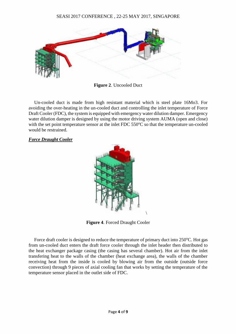
Force Draught Cooler
\
Figure 4. Forced Draught Cooler
Force draft cooler is designed to reduce the temperature of primary duct into 250oC. Hot gas
from un-cooled duct enters the draft force cooler through the inlet header then distributed to
the heat exchanger package casing (the casing has several chamber). Hot air from the inlet
transfering heat to the walls of the chamber (heat exchange area), the walls of the chamber
receiving heat from the inside is cooled by blowing air from the outside (outside force
convection) through 9 pieces of axial cooling fan that works by setting the temperature of the
temperature sensor placed in the outlet side of FDC.

SEASI 2017 CONFERENCE , 22-25 MAY 2017, SINGAPORE
Page 5 of 9
B. Performance Obstacles: Off-gas & Dust Settlement Increase
Figure 5. Process Flow of Dedusting Plant
Existing conditions described in this study is related to the operation of the process based on
EAF data testing after Performance Test of new Oxy Fuel Burner. Based on that testing, EAF
frequent trips / off time due to maximum limit of temperature in the primary duct (hot gas line)
was more than 700oC (600oC design), as shown in the following figure.
Figure 6. Dedusting System Trip Alarm due to Over Heat
If temperature of the hot gas line more than 700oC, then the corresponding dedusting Trip
Alarm System then the EAF will switch off (trip) and will be operated again after about 3
minutes when the temperature of the hot gas line has dropped to 625oC. This causes the power
on time and tap to tap time of EAF increases resulting in lower productivity.
Therefore the condition of dedusting system that often causes trip in EAF, then the way is taken
to reduce the utilization of Oxy Fuel Burner which is only using 2 lances (from a total of 3
1st
cooling stage
Gas cleaning
Primary dedusting
Secondary dedusting
2nd
cooling stage
Dedusting System Trip Alarm (yellow colour)

SEASI 2017 CONFERENCE , 22-25 MAY 2017, SINGAPORE
Page 6 of 9
units). This method is done to reduce the thermal load received Hot Gas Line and avoid the
occurrence of electricity trip.
III. DESIGN OF REVAMPED DEDUSTING PLANT
A. New Design Of Dedusting Plant
Carbon content in pig iron or hot metal varies considerably depending on the process source.
Typically pig iron will contain between 3 and 4.5 %. It is easy to see that use of large amounts of high
carbon materials must be balanced with oxygen availability in order that decarburization time is not
extended. The maximum practical decarburization rate in the EAF is much less than in the BOF due to
the shallow metal bath. Exceeding a rate of 0.1 % C per minute typically results in excessive metal
splashing and increased fume losses to the offgas system.
The term ∂E/∂t denotes the internal energy change of the gas stream due to combustion reactions
and evaporation of water spray in the gas phase. Post-combustion of CO and H2 bearing off-gasses
with air occurs in the first plant unit (drop out box, post combustion chamber, hot gas duct)/
Combustion reaction of CO, H2, and natural gas (CH4) from burners release energy to the off gas:
Figure 7. Influence of water cooling system to the off-gas temperature
SEASI 2017 CONFERENCE , 22-25 MAY 2017, SINGAPORE
Page 7 of 9
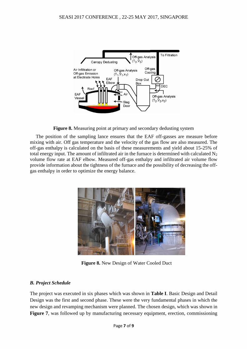
Figure 8. Measuring point at primary and secondary dedusting system
The position of the sampling lance ensures that the EAF off-gasses are measure before
mixing with air. Off gas temperature and the velocity of the gas flow are also measured. The
off-gas enthalpy is calculated on the basis of these measurements and yield about 15-25% of
total energy input. The amount of infiltrated air in the furnace is determined with calculated N2
volume flow rate at EAF elbow. Measured off-gas enthalpy and infiltrated air volume flow
provide information about the tightness of the furnace and the possibility of decreasing the off-
gas enthalpy in order to optimize the energy balance.
Figure 8. New Design of Water Cooled Duct
B. Project Schedule
The project was executed in six phases which was shown in Table I. Basic Design and Detail
Design was the first and second phase. These were the very fundamental phases in which the
new design and revamping mechanism were planned. The chosen design, which was shown in
Figure 7, was followed up by manufacturing necessary equipment, erection, commissioning

SEASI 2017 CONFERENCE , 22-25 MAY 2017, SINGAPORE
Page 8 of 9
and final acceptance.
TABLE I
Project Schedule of Revamping of EAF Dedusting Plant
No. Project Phase 2014 2015
6 7 8 9 10 11 12 1 2 3 4 5 6 7 8 9 10 11
1 Basic Design
2 Detail Design
3 Manufacturing
4 Erection
5 Commissioning
6 Final Acceptance
IV. RESULT & ANALYSIS
Individual test has been conducted to examine the function of all equipments which
consist of Cooled Duct, Un-cooled Duct, Force Drought Cooler, Mixing Chamber, Filter
System dan ID-Fan. The individual test result are as follow:
SEGMENT STANDARD (max) RESULT
Flow Fix L1 188 m3/h 188 m3/h
Flow Fix L2 183 m3/h 166 m3/h
Section 1 143 m3/h 113 m3/h
Section 2 143 m3/h 120 m3/h
NO PERFORMANCE WARRANTIES VALUE HASIL PERFORMANCE TEST
1. Inlet Force Draugh Cooler, Max (0C) 530 371
2. Inlet to filter chamber, Max (0C) 120 83
3. Dust Content, Max (mg/m3) 50 5
V. CONCLUSION
Based on the results of the implementations and analysis, some conclusions could be obtained
as follows:
1) Revamping of EAF Dedusting Plant could eliminate the impact of raw material
transformation in EAF (hot metal material based operation)

SEASI 2017 CONFERENCE , 22-25 MAY 2017, SINGAPORE
Page 9 of 9
2) By doing the revamping, transfer of knowledge was rapidly accelerated and the learning
time could be effectively shortened.
ACKNOWLEDGEMENTS
The acknowledgement was mainly given to the Board of Management of PT Krakatau Steel
(Persero) Tbk for issuing the permission to the authors in publishing this paper. The authors
would also like to acknowledge the Revamping Team from any discipline for their total
supports in succeeding the whole project phases.
REFERENCES
VAI, 1993, Plant Manual of SSP-2, PT Krakatau Steel, Cilegon.
Siemens VAI, 2010, Technical Specification of SSP 1 Revitalization Project, PT Krakatau
Steel, Cilegon.
PTKS, 2013, Profile of Central Workshop PT Krakatau Steel, PT Krakatau Steel, Cilegon.