Embed Size (px)
Citation preview

Operation Manual
www.critical-environment.com
LPT-A Analog Transmitter
Rev. G / H | 2015.05

2 © 2015 All rights reserved. Data subject to change without notice.
LPT-A - Operation Manual Rev. G / H | 2015.05
Table of ConTenTs1 POLICIES ..........................................................................................................5
1.1 Important Note ................................................................................................51.2 Warranty Policy ................................................................................................61.3 Service Policy ...................................................................................................61.4 Copyrights ........................................................................................................71.5 Dislclaimer .......................................................................................................81.6 Revisions ..........................................................................................................8
2 INTRODUCTION .............................................................................................92.1 General Description ..........................................................................................92.2 Key Features ...................................................................................................10
3 INSTRUMENT SPECIFICATIONS .................................................................113.1 Technical Specifications ..................................................................................113.2 Standard Enclosure Dimensions .....................................................................13
4 SENSOR SPECIFICATIONS ...........................................................................144.1 List of Available Sensors .................................................................................144.2 Calibration Extending Firmware (CEF) and Sensor Aging................................16
5 FEATURES & FUNCTIONS ............................................................................165.1 Exterior Enclosure ..........................................................................................165.2 Interior System Layout ...................................................................................18
5.2.1 Electrochemical Sensor ...................................................................................185.2.2 Solid State (Internal) Sensor............................................................................195.3.3 Solid State (Remote) Sensor ............................................................................20

© 2015 All rights reserved. Data subject to change without notice. 3
Rev. G /H | 2015.05 LPT-A - Operation Manual
6 INSTALLATION ..............................................................................................226.1 General Safety Warnings ................................................................................226.2 Protection Against Electrical Risks ..................................................................226.3 Protection Against Mechanical Risks ..............................................................236.4 System Installation ........................................................................................236.5 Sensor Mounting Heights ...............................................................................246.6 Enclosure Mounting Components ..................................................................26
6.6.1 Enclosure Base ................................................................................................266.6.2 Enclosure Bottom ............................................................................................27
6.7 Wiring Connections ........................................................................................276.7.1 Power & Output Connection ............................................................................276.7.2 Relay Connection ............................................................................................28Wiring Example: 3-Wire ...........................................................................................29Wiring Example: 4-Wire ...........................................................................................29Wiring Example: Relay .............................................................................................29Wiring Example: Remote Sensor ..............................................................................306.7.3 Remote Sensor Connection .............................................................................306.7.4 Wire Guage vs Run Length...............................................................................316.7.5 Open Loop .......................................................................................................32
7 OPERATION ...................................................................................................327.1 System Operation ...........................................................................................327.2 Fault Detection...............................................................................................337.3 Display Select .................................................................................................337.4 Enable / Disable the Buzzer ............................................................................347.5 Selecting the Output Signal ...........................................................................347.6 Test Function ..................................................................................................357.7 Setting the “Alarm” Level................................................................................367.8 Setting the Calibration Gas Level....................................................................37

4 © 2015 All rights reserved. Data subject to change without notice.
LPT-A - Operation Manual Rev. G / H | 2015.05
8 CALIBRATION ................................................................................................388.1 Calibration Specifications ...............................................................................38
8.1.1 Gas ..................................................................................................................388.1.2 Regulators & Flow ...........................................................................................398.1.3 Adapters..........................................................................................................398.1.4 Humidifier .......................................................................................................39
8.2 Calibrating Sensors ........................................................................................408.2.1 Calibration Frequency .....................................................................................408.2.2 Gas Testing Frequency (Bump Testing) ............................................................40
8.3 Calibration Procedure .....................................................................................40
9 ACCESSORIES ...............................................................................................479.1 Splash Guard ..................................................................................................479.2 Magnetic Wand ..............................................................................................489.3 Metal Protective Guard ..................................................................................489.4 Sample Draw Pump .......................................................................................499.5 Calibration Kit ................................................................................................50
10 MAINTENANCE ..........................................................................................50
11 TROUBLE SHOOTING ................................................................................51

© 2015 All rights reserved. Data subject to change without notice. 5
Rev. G /H | 2015.05 LPT-A - Operation Manual
1 PolICIes1.1 Important noteRead and understand this manual prior to using this instrument. Carefully read the warranty policy, service policy, notices, disclaimers and revisions on the following pages.
This product must be installed by a qualified electrician or factory trained technician and according to instructions indicated in this manual. This instrument should be inspected and calibrated regularly by a qualified and trained technician. For more information, refer to Section 8 Calibration and Section 10 Maintenance of this manual.
This instrument has not been designed to be intrinsically safe. For your safety, do not use it in classified hazardous areas (explosion-rated environments).
INSTRUMENT SERIAL NUMBER:
______________________________________________________
PURCHASE DATE:
______________________________________________________
PURCHASED FROM:
______________________________________________________
6 © 2015 All rights reserved. Data subject to change without notice.
LPT-A - Operation Manual Rev. G / H | 2015.05
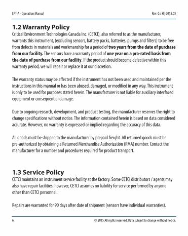
1.2 Warranty PolicyCritical Environment Technologies Canada Inc. (CETCI), also referred to as the manufacturer, warrants this instrument, (excluding sensors, battery packs, batteries, pumps and filters) to be free from defects in materials and workmanship for a period of two years from the date of purchase from our facility. The sensors have a warranty period of one year on a pro-rated basis from the date of purchase from our facility. If the product should become defective within this warranty period, we will repair or replace it at our discretion.
The warranty status may be affected if the instrument has not been used and maintained per the instructions in this manual or has been abused, damaged, or modified in any way. This instrument is only to be used for purposes stated herein. The manufacturer is not liable for auxiliary interfaced equipment or consequential damage.
Due to ongoing research, development, and product testing, the manufacturer reserves the right to change specifications without notice. The information contained herein is based on data considered accurate. However, no warranty is expressed or implied regarding the accuracy of this data.
All goods must be shipped to the manufacturer by prepaid freight. All returned goods must be pre-authorized by obtaining a Returned Merchandise Authorization (RMA) number. Contact the manufacturer for a number and procedures required for product transport.
1.3 service PolicyCETCI maintains an instrument service facility at the factory. Some CETCI distributors / agents may also have repair facilities; however, CETCI assumes no liability for service performed by anyone other than CETCI personnel.
Repairs are warranted for 90 days after date of shipment (sensors have individual warranties).

© 2015 All rights reserved. Data subject to change without notice. 7
Rev. G /H | 2015.05 LPT-A - Operation Manual
Should your instrument require non-warranty repair, you may contact the distributor from whom it was purchased or you may contact CETCI directly.
Prior to shipping equipment to CETCI, contact our office for an RMA #. All returned goods must be accompanied with an RMA number.
If CETCI is to do the repair work, you may send the instrument, prepaid, to: Attention: Service DepartmentCritical Environment Technologies Canada Inc.Unit 145, 7391 Vantage WayDelta, BC, V4G 1M3
Always include your Returned Merchandise Authorization (RMA) number, address, telephone number, contact name, shipping / billing information, and a description of the defect as you perceive it. You will be contacted with a cost estimate for expected repairs, prior to the performance of any service work.
For liability reasons, CETCI has a policy of performing all needed repairs to restore the instrument to full operating condition.
Pack the equipment well (in its original packing if possible), as we cannot be held responsible for any damage incurred during shipping to our facility.
1.4 CopyrightsThis manual is subject to copyright protection; all rights are reserved. Under international and domestic copyright laws, this manual may not be copied or translated, in whole or in part, in any manner or format, without the written permission of CETCI.

8 © 2015 All rights reserved. Data subject to change without notice.
LPT-A - Operation Manual Rev. G / H | 2015.05
1.5 DisclaimerUnder no circumstances will CETCI be liable for any claims, losses or damages resulting from or arising out of the repair or modification of this equipment by a party other than CETCI service technicians, or by operation or use of the equipment other than in accordance with the printed instructions contained within this manual or if the equipment has been improperly maintained or subjected to neglect or accident. Any of the forgoing will void the warranty.
Under most local electrical codes, low voltage wires cannot be run within the same conduit as line voltage wires. It is CETCI policy that all wiring of our products meet this requirement.
It is CETCI policy that all wiring be within properly grounded (earth or safety) conduit.
1.6 RevisionsThis manual was written and published by CETCI. The manufacturer makes no warranty or representation, expressed or implied including any warranty of merchantability or fitness for purpose, with respect to this manual.
All information contained in this manual is believed to be true and accurate at the time of printing. However, as part of its continuing efforts to improve its products and their documentation, the manufacturer reserves the right to make changes at any time without notice. Revised copies of this manual can be obtained by contacting CETCI or visiting www.critical-environment.com.
Should you detect any error or omission in this manual, please contact CETCI at the following address:
Critical Environment Technologies Canada Inc.Unit 145, 7391 Vantage Way, Delta, BC, V4G 1M3, Canada

© 2015 All rights reserved. Data subject to change without notice. 9
Rev. G /H | 2015.05 LPT-A - Operation Manual
Toll Free: +1.877.940.8741Telephone: +1.604.940.8741Fax: +1.604.940.8745Email: [email protected]: www.critical-environment.com
In no event will CETCI, its officers or employees be liable for any direct, special, incidental or consequential damages resulting from any defect in any manual, even if advised of the possibility of such damages.
2 InTRoDUCTIon2.1 General DescriptionThank you for purchasing our LPT-A Analog Transmitter.
The LPT-A transmitters are rugged, user-friendly analog gas detection transmitters for use in non-hazardous (non-explosion rated) environments such as commercial HVAC and light industrial applications.
A standard transmitter features a back lit, LCD digital display (refer to Section 3.1 Technical Specifications), analog output signal, one dry relay contact, audible alarm, and a standard water / dust tight enclosure.
LPT-A transmitters are available with sensors for many toxic gases (electrochemical sensors), oxygen (electrochemical), common refrigerants (solid state sensors), TVOCs (solid state sensor), and combustible (catalytic sensor). All LPT-A transmitters operate by diffusion. The sensors utilized in this device are accurate enough to measure to Occupational Health & Safety (OHS) hazardous levels for toxic gases.

10 © 2015 All rights reserved. Data subject to change without notice.
LPT-A - Operation Manual Rev. G / H | 2015.05
If after reading through the manual, you have any questions, please do not hesitate to contact our service department for technical support.
2.2 Key features• 3-wire VDC or 4-wire VAC power• 24 volt DC or AC power (nominal)• Linear 4 - 20 mA or 0 - 10 volt output signal• 1 dry contact relay, 30 volt 2 ampere maximum• Graphic LCD display (user selectable function)• Audible alarm• Standard water / dust tight, corrosion resistant enclosure (drip proof)
For splash or hose-down applications, add the optional splash guard. With the splash guard, the enclosure has an IP54 rating.
• Single sensor: electrochemical, catalytic for combustibles (internal or remote), solid state for refrigerants or TVOCs (internal or remote)
• RoHS compliant circuit boards• Easy maintenance• Economical• Includes sensor Calibration Extending Firmware (CEF) for some electrochemical sensors• Auto resetting fuse• Automated calibration procedure

© 2015 All rights reserved. Data subject to change without notice. 11
Rev. G /H | 2015.05 LPT-A - Operation Manual
3 InsTRUMenT sPeCIfICaTIons3.1 Technical specifications
MECHANICAL
Enclosure ABS / Polycarbonate
Weight 400 g (14 oz)
Size 5.0” x 5.0” x 2.1” (127 mm x 127 mm x 53.34 mm)
ELECTRICAL
Power Requirement3-wire mode4-wire mode
16 - 30 VDC, 3 W, Class 212 - 27 VAC, 50-60 Hz, 3 VA, Class 2
Use Class 2 transformer. See Section 6.7 Wiring Connections.
Outputs
Linear 4 - 20 mAMaximum 216 Ω load (wiring plus termination resistor) @ 12 VDCMaximum 316 Ω load (wiring plus termination resistor) @ 12 VAC
Voltage 0 - 10 voltMinimum 1k ohm load
Wiring
VDC (or ground referenced AC) three conductor shielded 18 awg (or larger) stranded within conduitVAC four conductor shielded 18 awg stranded within conduit(refer to Section 6.7.4 Wire Gauge vs. Run Length)

12 © 2015 All rights reserved. Data subject to change without notice.
LPT-A - Operation Manual Rev. G / H | 2015.05
Fuse Automatic resetting thermal
IndicatorGraphic LCDText prompting for calibration operation and fault indications.Installer configurable to suppress all other displays.
ENVIRONMENTAL
Operating Temperature
-20°C to 40°C (-4°F to 104°F)NOTE: Low temperature option available to -40°C (-40°F) (Sensor dependant, some extremely cold applications may require a small internal silicone heater to maintain temperature stability for sensor. Contact CETCI for details and pricing.)
Operating Humidity 15 - 90% RH non-condensing
CERTIFICATION
Conforms to: CSA-C22.2 No. 205-M1983 (R2009) / UL508 (Edition 17):2007
Conforms to: EMC Directive 2004/108/EC, EN 50270:2006, Type 1, EN61010
Conforms to: FCC. This device complies with part 15 of the FCC Rules, Operation is subject to the following two conditions: (1) This device may not cause harmful interference, and (2) this device must accept any interference received, including interference that may cause undesired operation.

© 2015 All rights reserved. Data subject to change without notice. 13
Rev. G /H | 2015.05 LPT-A - Operation Manual
3.2 standard enclosure Dimensions
Above dimensions are shown with optional splash guard. Without splash guard, thickness is 2.1 in (53.34 mm). The area required for enclosure door to be open 90 degrees is 6.13” (155.7 mm) or 9.6” (243.84 mm) for fully open. With the splash guard, the enclosure has an IP54 rating.
NOTE: Response time will be slower with a splash guard installed.

14 © 2015 All rights reserved. Data subject to change without notice.
LPT-A - Operation Manual Rev. G / H | 2015.05
4 sensoR sPeCIfICaTIons4.1 list of available sensors
SENSOR GAS TYPE PART NUMBER RANGE
Ammonia (NH3) LPT-A-NH3 0 - 500 ppm
Carbon Monoxide (CO) LPT-A-COA (3 year sensor) 0 - 200 ppm
Carbon Monoxide (CO) LPT-A-COB (6 year sensor) 0 - 200 ppm
Chlorine (Cl2) LPT-A-CL2 0 - 5.0 ppm
Ethylene (C2H4) LPT-A-C2H4 0 - 200 ppm
Ethylene Oxide (C2H4O) LPT-A-C2H4O 0 - 20 ppm
Formaldehyde (CH2O) LPT-A-CH2O 0 - 10 ppm
Hydrogen (H2) LPT-A-EH2 0 - 2,000 ppm
Hydrogen Sulphide (H2S) LPT-A-H2S 0 - 50 ppm
Hydrogen Chloride (HCl) LPT-A-HCL 0 - 20 ppm
Hydrogen Cyanide (HCN) LPT-A-HCN 0 - 100 ppm
Nitrogen Dioxide (NO2) LPT-A-NO2A (3 year sensor) 0 - 10 ppm
Nitrogen Dioxide (NO2) LPT-A-NO2B (7 year sensor) 0 - 10 ppm
Nitric Oxide (NO) LPT-A-NO 0 - 100 ppm
Oxygen (O2) LPT-A-O2 0 - 25.0% volume
Ozone (O3) LPT-A-O3 0 - 2 ppm
Phosphine (PH3) LPT-A-PH3 0 - 5 ppm

© 2015 All rights reserved. Data subject to change without notice. 15
Rev. G /H | 2015.05 LPT-A - Operation Manual
SENSOR GAS TYPE PART NUMBER RANGE
Silane (SiH4) LPT-A-SIH4 0 - 20 ppm
Sulphur Dioxide (SO2) LPT-A-SO2 0 - 20 ppm
Refrigerant (R22) LPT-A-R22 0 - 2,000 ppm
Refrigerant (R134A) LPT-A-R134A 0 - 2,000 ppm
Refrigerant (R402A) LPT-A-R402A 0 - 2,000 ppm
Refrigerant (R404A) LPT-A-R404A 0 - 2,000 ppm
Refrigerant (R407C) LPT-A-R407C 0 - 2,000 ppm
Refrigerant (R410A) LPT-A-R410A 0 - 2,000 ppm
Refrigerant (R422D) LPT-A-R422D 0 - 2,000 ppm
Refrigerant (R507) LPT-A-R507 0 - 2,000 ppm
TVOC (Isobutylene) LPT-A-STVOC 0 - 500 ppm
Hydrogen (H2) LPT-A-CH2 0 - 50% LEL
Methane (CH4) LPT-A-CH4 0 - 50% LEL
Propane (C3H8) LPT-A-C3H8 0 - 50% LEL

16 © 2015 All rights reserved. Data subject to change without notice.
LPT-A - Operation Manual Rev. G / H | 2015.05
4.2 Calibration extending firmware (Cef) and sensor agingSome LPT-A systems with certain electrochemical sensors have been programmed with our Calibration Extending Firmware (CEF). This firmware takes into consideration the aging of the sensors so that less frequent calibrations are acceptable in less-critical applications such as parking garages. The system tracks the age of the sensor and automatically compensates for the reduced output of the sensor as it ages.
5 feaTURes & fUnCTIons5.1 exterior enclosure

© 2015 All rights reserved. Data subject to change without notice. 17
Rev. G /H | 2015.05 LPT-A - Operation Manual
NUMBER FEATURE FUNCTION
Door Hinge Secures door
Display with gray border Indicates transmitter operation
Door Screw Secures door
Sensor Opening Allows gas diffusion into sensor
Padlock Opening For security padlock
Magnetic Calibration Trigger Point To enter calibration

18 © 2015 All rights reserved. Data subject to change without notice.
LPT-A - Operation Manual Rev. G / H | 2015.05
5.2 Interior system layout5.2.1 Electrochemical Sensor

© 2015 All rights reserved. Data subject to change without notice. 19
Rev. G /H | 2015.05 LPT-A - Operation Manual
5.2.2 Solid State (Internal) Sensor

20 © 2015 All rights reserved. Data subject to change without notice.
LPT-A - Operation Manual Rev. G / H | 2015.05
5.3.3 Solid State (Remote) Sensor
TMP
V+ SNS
GND
11

© 2015 All rights reserved. Data subject to change without notice. 21
Rev. G /H | 2015.05 LPT-A - Operation Manual
NUMBER FEATURE FUNCTION
Buzzer Enable Enables / disables the buzzer.
Rotary Encoder Sets calibration values, etc. with the jumpers.
Open Loop LEDLights if there is no connection for current output (always lit in voltage output mode).
Jumpers For calibration & test functions.
Calibrate State LED Further prompting for calibration operation.
Display EnableEnables / disables the display of the measured gas level.
Test Points: TP1 & TP2 For measuring voltage output.
Wiring Terminal Pluggable terminal for Power & signal output.
Output Select Select either current or voltage output.
Relay LEDIndicates (when on) that the gas level is above the trip point (the relay will indicate alarm level).
Relay Terminal Pluggable terminal for relay connections.
Remote Sensor Terminal Terminal for remote sensor connections.11

22 © 2015 All rights reserved. Data subject to change without notice.
LPT-A - Operation Manual Rev. G / H | 2015.05
6 InsTallaTIon6.1 General safety WarningsThe LPT-A is intended for indoor use, permanently mounted at a height that is appropriate for the type of gas being monitored. See Section 6.5 Sensor Mounting Heights. The LPT-A should be protected from extreme weather conditions.
The LPT-A requires no assembly and virtually no maintenance other than regular calibration of the integral and/or remote sensors and ensuring that excess water or dust is not somehow entering the enclosure and physically damaging the circuit board or internal components. There are no serviceable elements other than the calibration instructions outlined in this manual. There are no replaceable components except the sensors.
6.2 Protection against electrical RisksDisconnect all power before servicing. There may be multiple power sources. Power supply may have a building installed circuit breaker / switch that is suitably located and easy to access when servicing is required and should be labelled as LPT-A supply (disconnecting power to the LPT-A). Appropriate markings should be visible at the circuit breaker / switch that is supplying power to the LPT-A.
This device may interfer with pacemakers. Modern pacemakers have built-in features to protect them from most types of interference produced by other electrical devices you might encounter in your daily routine. If you a have a pacemaker, follow your healthcare provider’s instructions about being around this type of equipment.

© 2015 All rights reserved. Data subject to change without notice. 23
Rev. G /H | 2015.05 LPT-A - Operation Manual
6.3 Protection against Mechanical RisksThe door of the enclosure can be removed if absolutely necessary to facilitate installation of the base but it is not recommended on this version. Extreme care and caution must be exercised when removing the door to avoid damaging the hinges. The door should only be removed when absolutely required. Any damage occurring from door removal procedure will not be covered under warranty.
Simply grasp the door with one hand, being careful not to make contact with any of the internal components (circuit board), grasp the base with your other hand. Tug on the base and pull straight apart. DO NOT TWIST. The section of the hinges located on the base should “snap” apart from the part of the hinges located on the door.
After installation, simply locate the lid hinges over the installed base hinges and pull toward you. The hinges should easily “snap” back into place.
The enclosure has one screw securing the door to the base for electrical safety and provides an opening to allow the user to apply a padlock or tie wrap if they desire the transmitter to be locked. See Section 5.1 Exterior Enclosure.
Be aware that the hinged door that could potentially pinch fingers and the sharp edges and/or jumper pins on the board could potentially prick or cut fingers if not handled carefully.
6.4 system InstallationThe LPT-A should be installed on a flat vertical surface using the four 0.175” (4.4 mm) diameter mounting holes provided to maintain water tight status. Care should be taken to ensure that the face of the LPT-A is not obstructed in order to maximize the sensor’s exposure to the environment being monitored.
24 © 2015 All rights reserved. Data subject to change without notice.
LPT-A - Operation Manual Rev. G / H | 2015.05
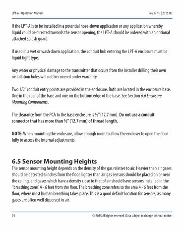
If the LPT-A is to be installed in a potential hose-down application or any application whereby liquid could be directed towards the sensor opening, the LPT-A should be ordered with an optional attached splash guard.
If used in a wet or wash down application, the conduit hub entering the LPT-A enclosure must be liquid tight type.
Any water or physical damage to the transmitter that occurs from the installer drilling their own installation holes will not be covered under warranty.
Two 1/2” conduit entry points are provided in the enclosure. Both are located in the enclosure base. One in the rear of the base and one on the bottom edge of the base. See Section 6.6 Enclosure Mounting Components.
The clearance from the PCA to the base enclosure is ½” (12.7 mm). Do not use a conduit connector that has more than ½” (12.7 mm) of thread length.
NOTE: When mounting the enclosure, allow enough room to allow the end user to open the door fully to access the internal adjustments.
6.5 sensor Mounting HeightsThe sensor mounting height depends on the density of the gas relative to air. Heavier than air gases should be detected 6 inches from the floor, lighter than air gas sensors should be placed on or near the ceiling, and gases which have a density close to that of air should have sensors installed in the “breathing zone” 4 - 6 feet from the floor. The breathing zone refers to the area 4 - 6 feet from the floor, where most human breathing takes place. This is a good default location for sensors, as many gases are often well dispersed in air.

© 2015 All rights reserved. Data subject to change without notice. 25
Rev. G /H | 2015.05 LPT-A - Operation Manual
GAS APPLICATIONS / TYPES SUGGESTED MOUNTING HEIGHT
Carbon Monoxide (CO) Gas engine exhaust4 - 6 ft above the floor
Nitrogen Dioxide (NO2) Diesel engine exhaust
Propane (C3H8) Propane fuel 6” above the floor
Methane (CH4) Buildings built on landfill sitesNear the ceiling
Ammonia (NH3)Commercial ice rink compressor rooms
For more examples, visit www.critical-environment.com/sensor-mounting.

26 © 2015 All rights reserved. Data subject to change without notice.
LPT-A - Operation Manual Rev. G / H | 2015.05
6.6 enclosure Mounting Components6.2.1 Enclosure Base
NUMBER FEATURE
Door Hinge
1/2” Conduit Entry Knockout
Mounting Holes

© 2015 All rights reserved. Data subject to change without notice. 27
Rev. G /H | 2015.05 LPT-A - Operation Manual
6.2.2 Enclosure Bottom
NUMBER FEATURE
Door Hinge
1/2” Conduit Entry Knockout
6.7 Wiring ConnectionsAll wiring should be run within properly grounded (earth or safety) conduit. Signal output and supply should be in shielded cable. The cable shield should be connected to earth ground at the controller/power supply that is providing power for the LPT-A.
6.7.1 Power & Output ConnectionThe LPT-A analog transmitter is a low voltage powered device. Any application of operating voltages higher than indicated in the specification may result in damage. Double check wiring connections prior to powering the transmitter. Damage from incorrect wiring connections or from too much voltage applied is not covered under warranty. Refer to Wiring Examples on the next page.

28 © 2015 All rights reserved. Data subject to change without notice.
LPT-A - Operation Manual Rev. G / H | 2015.05
If the installer is powering the LPT-A with four wire 24 VAC, the VAC wires should be connected to the terminal “one” (AC) and terminal “two” (AC / DC), from the top down. The signal return should be connected to terminal “three” (GND). The “signal” (4 - 20 mA or 0 - 10 volt) wire is always connected to terminal “four”. Refer to Wiring Examples on the next page. If the installer is powering the LPT-A with three wire 24 VDC or ground referenced AC, the “positive” wire should be connected to terminal “two” (AC / DC) and the negative wire should be connected to terminal “three” (GND). The “signal” (4 - 20 mA or 0 - 10 volt) wire is always connected to terminal “four”. Refer to Wiring Examples on the next page.
6.7.2 Relay ConnectionThe relay operates in “failsafe” mode, i.e. the relay coil is energized under normal non-alarm conditions. The relay is de-energized when the detected gas level is greater than or equal to the trip point, if a fault is detected, or if power fails.
In most applications the relay function should use the common “COM” and normally closed “NC” terminals. With this wiring the connection will be open under normal, low gas concentration conditions. When the gas concentration rises (or if there is a fault, or power failure) the connection relay will close and signal the control panel or fan control.
NOTE: DO NOT USE SOLID-CORE WIRE AT THE WIRING TERMINAL STRIPS. The rigidity of solid-core wire can pull a soldered terminal strip completely off a circuit board and “this will not be covered under warranty”.
The wiring terminal strips on the LPT-A circuit board can be unplugged for easier wiring installation. Grasp the two sides of the terminal strip and pull sideways.

© 2015 All rights reserved. Data subject to change without notice. 29
Rev. G /H | 2015.05 LPT-A - Operation Manual
Wiring Example: 3-Wire
Wiring Example: 4-Wire
Wiring Example: Relay

30 © 2015 All rights reserved. Data subject to change without notice.
LPT-A - Operation Manual Rev. G / H | 2015.05
Wiring Example: Remote Sensor
Device must be used with rated equipment. External power to LPT-A must be supplied by a Class 2 or better transformer.
6.7.3 Remote Sensor ConnectionFour-conductor, 16-18 awg stranded shielded cable is required for the Remote Sensor Wiring. This wiring should be run in a conduit, separate from the signal output, and should not exceed 500 feet. The voltage at the remote sensor (Red V+ to Black GND) should be 5 VDC ± 2%. If this voltage is not met after installation, the wrong gauge wire may have been used or the wiring run is too long.
Catalytic or solid state sensor breathes through these openings.
Wiring:• Red (V+)• Yellow (Signal)• Black (Ground)• White (Temperature)
V+
TMP
SNS
GND
LPT-A Remote Sensor
RED
WHITE
YELLOW
BLACK

© 2015 All rights reserved. Data subject to change without notice. 31
Rev. G /H | 2015.05 LPT-A - Operation Manual
6.7.4 Wire Gauge vs Run Length
SUPPLY VOLTAGEMAXIMUM LOAD
(Wire + Termination Resistor) (ohms)
WIRE GAUGE (awg) MAXIMUM CABLE LENGTH (feet)
24 VDC 592
20 4,400
18 7,100
16 10,700
16 VDC216 (assume a 200 Ω termination resistor)
20 700
18 1,200
16 1,800
24 VAC 1,060
20 27,000
18 43,200
16 65,500
12 VAC316 (assume a 200 Ω termination resistor)
20 5,600
18 8,900
16 13,583
NOTE: The termination resistor could be as high as 500 Ω (10 volt measurement at 20 mA). A poor quality 24 VAC transformer might supply as little as 14 volts at low line conditions.
Upon application of power, the display will show the gas formula (e.g. NO2), the units of measurement (e.g. PPM), and a “WARM UP” message. During this warm-up period (typically five minutes, but varies with sensor type) the output signal is fixed at 4.0 mA (current) or 0 volt

32 © 2015 All rights reserved. Data subject to change without notice.
LPT-A - Operation Manual Rev. G / H | 2015.05
(voltage). After the warm up period, the system may exhibit gas alarm condition if the sensor has not completely stabilized during the warm up period. This is normal and the length of time the gas alarm exists is dependent upon the length of time since the unit was last powered up and the state of the environment it is installed in.
After warm up the display will show the current gas reading, if the display jumper is in the ENable position. If the display jumper is in the DISable position the display will continue to show the gas type, but will not display the units or gas reading.
6.7.5 Open LoopIf the 4 - 20 mA signal loop has not been connected properly or has been damaged in some manner between the analog transmitter and the device to which it is sending its signal output, the LPT-A will show an open loop icon OL at the bottom right of the display, as well as turning on the internal open loop LED. At this point, the wiring should be inspected for problems.
NOTE: If the voltage output is chosen, the open loop indicators will always be on.
7 oPeRaTIon7.1 system operationNormal operation is indicated by the display showing the gas reading or the gas formula.
During normal operation, the gas level will be reported through the current loop (or voltage) output, and a rough reading can be obtained from the voltage test points.
© 2015 All rights reserved. Data subject to change without notice. 33
Rev. G /H | 2015.05 LPT-A - Operation Manual
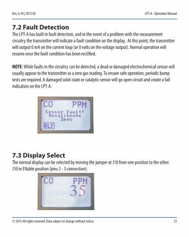
7.2 fault DetectionThe LPT-A has built in fault detection, and in the event of a problem with the measurement circuitry the transmitter will indicate a fault condition on the display. At this point, the transmitter will output 0 mA on the current loop (or 0 volts on the voltage output). Normal operation will resume once the fault condition has been rectified.
NOTE: While faults in the circuitry can be detected, a dead or damaged electrochemical sensor will usually appear to the transmitter as a zero gas reading. To ensure safe operation, periodic bump tests are required. A damaged solid-state or catalytic sensor will go open circuit and create a fail indication on the LPT-A.
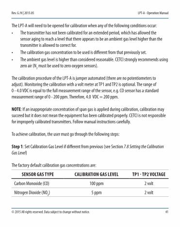
7.3 Display selectThe normal display can be selected by moving the jumper at J10 from one position to the other.J10 in ENable position (pins 2 - 3 connection):

34 © 2015 All rights reserved. Data subject to change without notice.
LPT-A - Operation Manual Rev. G / H | 2015.05
The display will show the gas formula, the units and the current gas level. This is the factory default position.
J10 in DISable position (pins 1 - 2 connected):
The display will show abnormal conditions, e.g. fault, etc., but will not show gas readings.The display will always show messages for service functions, e.g. test, calibrate, etc.
7.4 enable / Disable the buzzerThe buzzer can be disabled (the factory default is to disable the buzzer) by moving the jumper at J5 from the ON (pins 2 - 3 connected) to the OFF position (pins 1 - 2 connected).
7.5 selecting the output signalThe default signal output mode is 4 - 20 mA current loop. Zero concentration gas will output 4 mA and full scale (e.g. 200 ppm CO) will output 20 mA.
The output can be changed to voltage (0 - 10 volt) by moving the jumper at J6 from the I position (pins 2 - 3 connected) to the V position (pins 1 - 2 connected). The voltage signal will swing from zero (0) volts to indicate no gas detected, to 10 volts to indicate full scale gas detected.

© 2015 All rights reserved. Data subject to change without notice. 35
Rev. G /H | 2015.05 LPT-A - Operation Manual
7.6 Test functionDuring warm up and normal operation, the signal output (current or voltage), the relay and the buzzer (if enabled) can be tested using the jumpers at J7.
Placing a jumper on the OVER / DESC / TEST position (while there are no jumpers on the SETPOINT, or CALGAS positions) will initiate the test function. The current (or voltage) output will match the span gas level, and will remain at that level until the jumper is removed from the OVER / DESC / TEST position or for 5 minutes.
Note that the relay and buzzer (if enabled) will be tested, even if the SETPOINT is higher than the span gas level.
During the test the display will show the span gas value, and an icon indicating that the LPT-A is in the test mode:
After 5 minutes (or when the jumper is removed from the OVER / DESC / TEST position), the unit will return to normal operation.
Please return the jumper placed on the OVER / DESC / TEST location to an IDLE position when testing is completed.

36 © 2015 All rights reserved. Data subject to change without notice.
LPT-A - Operation Manual Rev. G / H | 2015.05
Voltage Output to Test Points “TP-1” and “TP-2”: Attach a volt meter’s leads to the two test points (TP-1 & TP-2) located on the lower left corner on the back of the circuit board. Set the meter to volts DC with one decimal point. The range of 0 - 4.0 VDC is equal to the full measurement range of the sensor. e.g. a CO sensor has a standard measurement range of 0 - 200 ppm, therefore 2.0 VDC = 100 ppm, 4.0 VDC = 200 ppm.
7.7 setting the “alarm” levelThe Alarm level is the gas concentration at (and above which) the relay will indicate a high gas level, the buzzer will sound (if enabled) and the display will indicate an alarm condition (if enabled).
The set point can be changed by:• Moving a jumper from one of the IDLE positions to the SETPOINT position,• Rotate the shaft of the encoder, E1, clockwise to increase the set point or counter-clockwise to
decrease the set point,• The set point will be displayed, along with a “SETPOINT” icon indicating that the set point is
being changed,
• The set point can also be monitored with a volt meter connected between TP1 and TP2. The
value will be a zero to four volt signal proportional to the set point level. For example; the maximum range for CO is 200 ppm, so 50 ppm (¼ of the range) will be indicated by a voltage between TP1 and TP2 of 1 volt.

© 2015 All rights reserved. Data subject to change without notice. 37
Rev. G /H | 2015.05 LPT-A - Operation Manual
• After the set point is changed as desired, move the jumper from the SETPOINT position back to the IDLE position.
If the LPT-A happens to be an oxygen transmitter, it supports both an ascending and a descending alarm point. The factory default ascending set point is 23.0 %volume and the descending is 19.5% volume (normal atmospheric oxygen content is 20.9% vol). The descending point can be set by placing jumpers at both the SETPOINT and the OVER / DESC / TEST position.
If there is no activity (turning the encoder shaft) for 5 minutes, the LPT-A will return to normal mode. After returning to normal mode the jumper will have to be moved from the SETPOINT position to the IDLE position and then re-installed at the SETPOINT position if further adjustment is needed.
SENSOR GAS TYPE TRIP POINT (ALARM LEVEL) TP1 - TP2 VOLTAGE
Carbon Monoxide (CO) 25 ppm 0.5 volts
Nitrogen Dioxide (NO2) 0.7 ppm 0.28 volts
Solid State Refrigerants 250 ppm 0.5 volts
Combustible 10% LEL 0.8 volts
For more examples, visit www.critical-environment.com/calibration-alarm.
7.8 setting the Calibration Gas levelThe calibration gas concentration can be changed in the same fashion as the set point:• Move a jumper from an IDLE position to the CALGAS position• Rotate the shaft of the encoder, E1, to increase or decrease the calibration gas value.

38 © 2015 All rights reserved. Data subject to change without notice.
LPT-A - Operation Manual Rev. G / H | 2015.05
• The display will show the calibration gas value and a “CALGAS” icon.
• While adjusting the calibration gas value a corresponding voltage will be signaled on the test
points TP-1 and TP-2. For example: a common calibration gas for CO is 100 ppm, which is half the range, so 2 volts at the test points indicates 100 ppm.
• After changing the calibration gas level move the jumper from the CALGAS position back to the IDLE position.
• If the encoder is not rotated for 5 minutes the transmitter will automatically return to normal operation. The jumper will have to be removed and re-installed at the CALGAS position if further adjustment is required.
8 CalIbRaTIon8.1 Calibration specifications8.1.1 GasCalibration span gases should have at least ± 5% accuracy and have a current date stamp. Gas generators should have a current dated cell installed. Service personnel should flow zero emissions air or 20.9% volume O2 (scrubbed of hydrocarbons) before attempting to null adjust toxic gas sensors. In some cases nitrogen (N2) can be substituted for zero air when null adjusting electrochemical sensors. Contact CETCI for clarification.
Every LPT-A transmitter is calibrated in a chamber by true diffusion method prior to leaving our facility. This method more closely emulates actual “real world” conditions. Field calibration

© 2015 All rights reserved. Data subject to change without notice. 39
Rev. G /H | 2015.05 LPT-A - Operation Manual
using gas cylinder, regulator and hose directing span gas into the sensor may result in slightly higher readings. It is important to note that the type of gas mixture, how old the gas is and what temperature it has been stored at will also affect repeatability during field calibration.
NOTE: • Oxygen sensors require 100% N2 for a true zero.• Solid-state and catalytic sensors require oxygen to work and thus the user MUST flow clean air
or oxygen to obtain a true zero and the span gas must have “air” balance, not N2 balance.
8.1.2 Regulators & FlowCalibration gases that are lighter than or the same weight as air (CO, O2, etc.) should be flowed at 0.5 LPM. Gases heavier than air (NO2, etc.) should be flowed between 0.5 and 1.0 LPM. Fixed flow regulators provide more accuracy.
8.1.3 AdaptersThe proper calibration adapter should be utilized to allow the gas to properly diffuse around the sensor. They are available from CETCI under part number CET-7000-CAP, for an LPT-A without a splash guard or splash guard calibration cap, part number CET-4700-SCC, for an LPT-A with a splash guard or part number CET-8000-GRS, for an LPT-A with a remote sensor head.
8.1.4 HumidiferFor refrigerant sensors (solid state), an inline humidifier is required for all operations with bottled gas (bump test zero and span).

40 © 2015 All rights reserved. Data subject to change without notice.
LPT-A - Operation Manual Rev. G / H | 2015.05
8.2 Calibrating sensors8.2.1 Calibration Frequency
• Parking garage detectors: Once every 12 months• OHS applications: Once every 6 months (OHS: Occupational Health & Safety)• For best performance and to meet published specifications: once every six months
8.2.2 Gas Testing Frequency (Bump Testing)For the purpose of safety in OHS applications, sensors should be gas tested (bump tested) once every month to confirm response and alarm activation.
NOTE: A calibration label should be applied after every calibration to confirm work performed and the date it was confirmed. If a controller is involved, the alarm set points should be indicated on a label on the front door of the enclosure so anyone working in the environment can be aware.
Required Equipment: Calibration kit, Calibration gasesOptional: Digital multi-meter
Users can order the calibration kit, calibration accessories and / or gases from any CETCI authorized distributor or they can supply their own gas and equipment as long as the gas meets the minimum specifications. CETCI does not ship gases outside of North America.
8.3 Calibration ProcedureCalibration can normally be performed without opening the transmitter. A magnetic calibration wand (CETCI part number CET-MW) is available from CETCI and is used to touch the enclosure at the lower left edge of the vent opening (refer to page 16 of this manual for location photo).
A second touch with the calibration wand can be used to cancel the current calibration step.
© 2015 All rights reserved. Data subject to change without notice. 41
Rev. G /H | 2015.05 LPT-A - Operation Manual
The LPT-A will need to be opened for calibration when any of the following conditions occur:• The transmitter has not been calibrated for an extended period, which has allowed the
sensor aging to reach a level that there appears to be an ambient gas level higher than the transmitter is allowed to correct for.
• The calibration gas concentration to be used is different from that previously set.• The ambient gas level is higher than considered reasonable. CETCI strongly recommends using
zero air (N2 must be used to zero oxygen sensors).
The calibration procedure of the LPT-A is jumper automated (there are no potentiometers to adjust). Monitoring the calibration with a volt meter at TP1 and TP2 is optional. The range of 0 - 4.0 VDC is equal to the full measurement range of the sensor, e.g. CO sensor has a standard measurement range of 0 - 200 ppm. Therefore, 4.0 VDC = 200 ppm.
NOTE: If an inappropriate concentration of span gas is applied during calibration, calibration may succeed but it does not mean the equipment has been calibrated properly. CETCI is not responsible for improperly calibrated transmitters. Follow manual instructions carefully.
To achieve calibration, the user must go through the following steps:
Step 1: Set Calibration Gas Level if different from previous (see Section 7.8 Setting the Calibration Gas Level)
The factory default calibration gas concentrations are:
SENSOR GAS TYPE CALIBRATION GAS LEVEL TP1 - TP2 VOLTAGE
Carbon Monoxide (CO) 100 ppm 2 volt
Nitrogen Dioxide (NO2) 5 ppm 2 volt

42 © 2015 All rights reserved. Data subject to change without notice.
LPT-A - Operation Manual Rev. G / H | 2015.05
Solid State Refrigerants 1,000 ppm 2 volt
Combustible 20% LEL 1.6 volt
For more examples, visit www.critical-environment.com/calibration-gas-concentration.
Step 2: Expose to clean air:• Attach regulator to cylinder of zero air (nitrogen is used to zero oxygen sensors).• Insert the calibration adapter into the sensor opening in the front of the enclosure door.
• Use a slight twisting motion as you gently push the calibration adapter into the sensor opening.
• If the calibration adapter is hard to insert, moisten the O-ring seal slightly then try re-inserting it.
• If the optional splash guard is installed, use the large cup adapter (part number CET-4700-SCC) and place it over the splash guard.
• Open regulator valve fully allowing zero air (N2) to flow over sensor for one minute. As the amount of oxygen decreases, it will trigger the descending alarm point and the alarm will go off.
• In some situations using ambient air instead of zero air is possible, but refer to the limitations in Step 4.
Step 3: Trigger the calibration by:• Touching the enclosure of the LPT-A with a magnet wand (below and just left of the gas vent
opening) or• Moving an internal jumper from a J7 IDLE position to the CAL position.

© 2015 All rights reserved. Data subject to change without notice. 43
Rev. G /H | 2015.05 LPT-A - Operation Manual
The LPT-A will use the last four seconds of gas data to determine the zero calibration level.
Depending on the reading the LPT-A will show one of the following messages:• ZERO ACCEPTED - proceed to Step 5
• ZERO OUT OF RANGE, OVERRIDE? - proceed to Step 4
• ZERO FAILED! RECALIBRATE - see Section 7.2 Fault Detection

44 © 2015 All rights reserved. Data subject to change without notice.
LPT-A - Operation Manual Rev. G / H | 2015.05
Step 4: Possible Override• If the zero level appears too high (the ambient air might have a slight background of the
target gas present, or it might have been so long since the last calibration that the sensor has drifted), the display will show “ZERO OUT OF RANGE, OVERRIDE?” and the internal Calibrate State LED will flash with a short OFF time and long ON time.
• To cancel calibration, move the jumper from the CAL position back to the IDLE position. The display will show:
• To override, move the second IDLE jumper from its rest position to the OVER / DESC / TEST
position.• If the jumper is not moved to the OVER position within 30 seconds, the calibration will be
cancelled and the LPT-A will return to normal mode.• After using the OVER / DESC / TEST position, the second IDLE jumper should be returned to its
rest position.
Step 5: Zero Accepted

© 2015 All rights reserved. Data subject to change without notice. 45
Rev. G /H | 2015.05 LPT-A - Operation Manual
• Once zeroed, the display will show ‘FLOW GAS’ and the internal calibrate state LED will flash four times and then paused with the LED off.
• Disconnect the zero air (N2) from the calibration adapter.
Step 6: Attach hose from the bottle of calibration gas to the calibration adapter.• Ensure that the adapter has not fallen out of the transmitter’s sensor opening.
Step 7: Open regulator valve fully and allow span gas to flow over sensor.• If no gas is detected after one minute, the transmitter returns to normal operation and the
procedure will need to be repeated from Step 2.
Step 8: Wait for stable reading• Once gas flow is detected, the display will show ‘WAITING FOR STABLE READING’.
• The calibrate state LED pattern will flash four times and then pause with the LED on. During
this time the TP1 voltage will follow the gas level based on the ideal span of the sensor.
46 © 2015 All rights reserved. Data subject to change without notice.
LPT-A - Operation Manual Rev. G / H | 2015.05
• Spanning can be cancelled by removing the jumper from the CAL position; return it to the IDLE position. Note that the zero value set in Step 5 is not cancelled.
• If spanning times out without an acceptable value the display will show ‘SPAN FAILED! RECALIBRATE’.
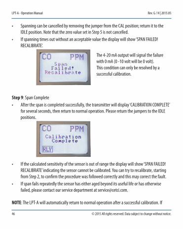
Step 9: Span Complete• After the span is completed successfully, the transmitter will display ‘CALIBRATION COMPLETE’
for several seconds, then return to normal operation. Please return the jumpers to the IDLE positions.
• If the calculated sensitivity of the sensor is out of range the display will show ‘SPAN FAILED!
RECALIBRATE’ indicating the sensor cannot be calibrated. You can try to recalibrate, starting from Step 2, to confirm the procedure was followed correctly and this may correct the fault.
• If span fails repeatedly the sensor has either aged beyond its useful life or has otherwise failed, please contact our service department at [email protected].
NOTE: The LPT-A will automatically return to normal operation after a successful calibration. If
The 4-20 mA output will signal the failure with 0 mA (0 -10 volt will be 0 volt). This condition can only be resolved by a successful calibration.

© 2015 All rights reserved. Data subject to change without notice. 47
Rev. G /H | 2015.05 LPT-A - Operation Manual
the calibration gas is still applied the level will be reflected on the output signal, and relay, which could cause a control panel to enter an alarm state. If the span calibration was not successful the LPT-A will display ‘CALIBRATION FAILED! RECALIBRATE’ and output 0 mA (0 volts) until a successful calibfation is performed.
NOTE: Some sensors and gas (e.g. refrigerants) will continue to climb as long as gas is applied. CETCI uses a 2 minute mark for calibration in these cases.
To exit calibration at any time, either:• Touch the enclosure with the calibration wand a second time or• Remove the jumper from the CAL position and return it to the IDLE position
If the digital multi-meter leads are attached to test points TP-1 and TP-2, the measured voltage will start moving towards the voltage calculated for the span gas value.
9 aCCessoRIes9.1 splash Guard
The splash guard attaches to the front of the enclosure and when attached the enclosure meets IP54 standards. Factory installed only.

48 © 2015 All rights reserved. Data subject to change without notice.
LPT-A - Operation Manual Rev. G / H | 2015.05
9.2 Magnetic Wand
Part Code: CET-MW
The magnetic wand is used for non intrusive calibration.
Lifts ½ lb solid steel
Size 2 5/8” X 1/4” Hexagon
9.3 Metal Protective Guard
Part Code: SCS-8000-RSG

© 2015 All rights reserved. Data subject to change without notice. 49
Rev. G /H | 2015.05 LPT-A - Operation Manual
The metal protective guard is heavy duty metal protective guard to help protect against abrasive damage, theft and vandalism to the transmitters. This is an added preventative in addition to the product enclosure.
It is made from 16-gauge galvanized steel and has ½” (13 mm) square openings in the front to allow gas and air to flow through to the sensor. With only four slotted mounting holes, installation and removal for gas detector servicing is easy.
Enclosure 16 gauge galvanized steel
Weight 800 g (28 oz)
Size 7.0” W x 6.3” H x 3.6” D (178 mm W x 160 mm H x 91 mm D)
9.4 sample Draw Pump
Part Code: PRU-24-A (for 24 VAC) or PRU-24-D (for 24 VDC)

50 © 2015 All rights reserved. Data subject to change without notice.
LPT-A - Operation Manual Rev. G / H | 2015.05
Self contained sample draw pump units that can be utilized with any CETCI systems or transmitters. Units include sample pump, flow meter, in-line particulate filter and watertight polycarbonate enclosure. Operating power is 24 VDC or VAC (please specify at time of order).
9.5 Calibration Kit
Part Code: CET-715A-CK1
Calibration kits and gases are available from the CETCI factory. Many gases are carried in inventory but not all. Check with any CETCI authorized distributor for availability of specific gas types. Gas cylinders cannot be shipped overseas.
10 MaInTenanCeThe LPT-A transmitter requires virtually no maintenance other than regular calibration of the sensor.
The transmitter should be monitored for possible damaging conditions.• The sensor port should be kept free of dirt or soot build up.

© 2015 All rights reserved. Data subject to change without notice. 51
Rev. G /H | 2015.05 LPT-A - Operation Manual
• If in a damp location, source of water should be shielded from contacting the top of the transmitter.
• If located in a working area, the front of the transmitter should be kept clear. • If painting is to be conducted in the transmitter’s location the transmitter needs to be
protected from over spray and the sensor port should not receive paint fumes – these fumes may damage or reduce the life of the sensor.
11 TRoUble sHooTInGLPT-A won’t power up. (blank display)Is the power properly connected? Refer to Wiring Examples. Check the connections.
Display shows a fault message and the current loop will output 0 mA. The LPT-A is in fault mode. If re-calibrating the sensor fails, replace the transmitter.
During calibration the display shows “override” message.The sensor needs override. Move the second IDLE jumper to the OVER / DESC / TEST position.
Display shows “Span Fail. Recalibrate”.It failed calibration. Try to recalibrate the sensor again.
LPT-A powered up (display appears normal) but the control panel will display “Fault”.4 - 20 mA signal loop has not been connected properly. Check the connections and refer to Wiring Examples.

Critical Environment Technologies Canada Inc.Unit 145, 7391 Vantage Way, Delta, BC, V4G 1M3, Canada
Toll Free: +1.877.940.8741 Tel: +1.604.940.8741Fax: +1.604.940.8745
www.critical-environment.com
© 2015 Critical Environment Technologies Canada Inc. All rights reserved. Data in this publication may change without notice.
LPTA20150521-GH