Embed Size (px)
Citation preview
Rev. Apr. 7, 2008
Preparing for SCRF Meeting
to be held at Fermilab, April 21-25
Report from
Meetings at SLAC and Fermilab
Akira YamamotoApril 6, 2008
1
Rev. Apr. 7, 2008
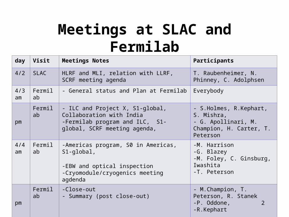
Meetings at SLAC and Fermilabday Visit Meetings Notes Participants
4/2 SLAC HLRF and MLI, relation with LLRF, SCRF meeting agenda
T. Raubenheimer, N. Phinney, C. Adolphsen
4/3 am
Fermilab - General status and Plan at Fermilab Everybody
pm
Fermilab - ILC and Project X, S1-global, Collaboration with India-Fermilab program and ILC, S1-global, SCRF meeting agenda,
- S.Holmes, R.Kephart, S. Mishra, - G. Apollinari, M. Champion, H. Carter, T. Peterson
4/4 am
Fermilab -Americas program, S0 in Americas, S1-global,
-EBW and optical inspection-Cryomodule/cryogenics meeting agdenda
-M. Harrison-G. Blazey-M. Foley, C. Ginsburg, Iwashita-T. Peterson
pm
Fermilab -Close-out- Summary (post close-out)
- M.Champion, T. Peterson, R. Stanek-P. Oddone,-R.Kephart
2
Rev. Apr. 7, 2008
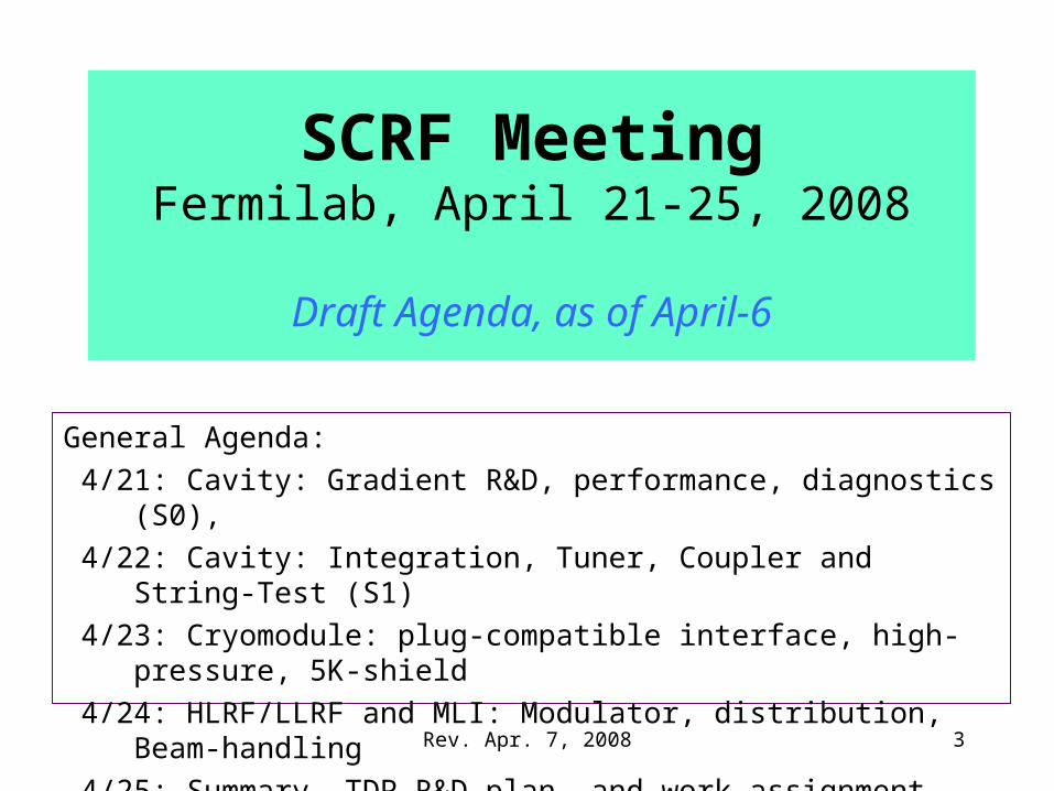
SCRF MeetingFermilab, April 21-25, 2008
Draft Agenda, as of April-6
General Agenda:
4/21: Cavity: Gradient R&D, performance, diagnostics (S0),
4/22: Cavity: Integration, Tuner, Coupler and String-Test (S1)
4/23: Cryomodule: plug-compatible interface, high-pressure, 5K-shield
4/24: HLRF/LLRF and MLI: Modulator, distribution, Beam-handling
4/25: Summary, TDP R&D plan, and work-assignment
3
Rev. Apr. 7, 2008
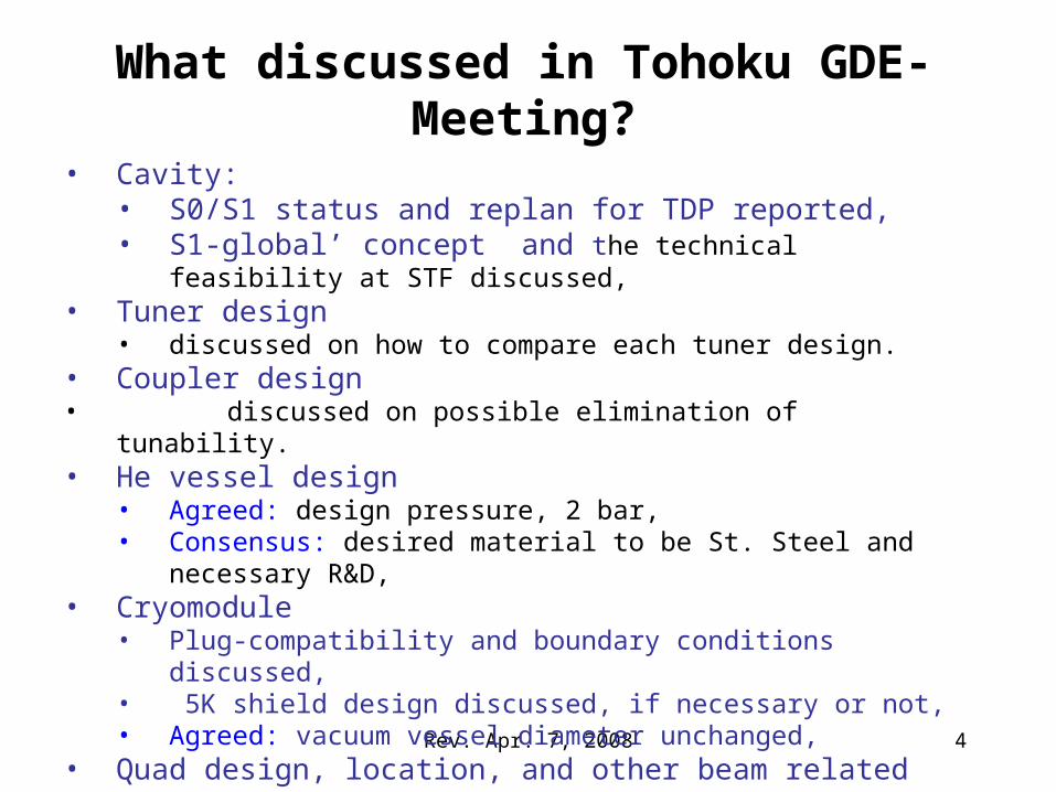
• Cavity: • S0/S1 status and replan for TDP reported,• S1-global’ concept and the technical feasibility at STF discussed,
• Tuner design• discussed on how to compare each tuner design.
• Coupler design• discussed on possible elimination of tunability.• He vessel design
• Agreed: design pressure, 2 bar, • Consensus: desired material to be St. Steel and necessary R&D,
• Cryomodule• Plug-compatibility and boundary conditions discussed, • 5K shield design discussed, if necessary or not,• Agreed: vacuum vessel diameter unchanged,
• Quad design, location, and other beam related issue• Agreed: to locate at center, with alignment tolerance <0.3 mm
What discussed in Tohoku GDE-Meeting?
4
Rev. Apr. 7, 2008
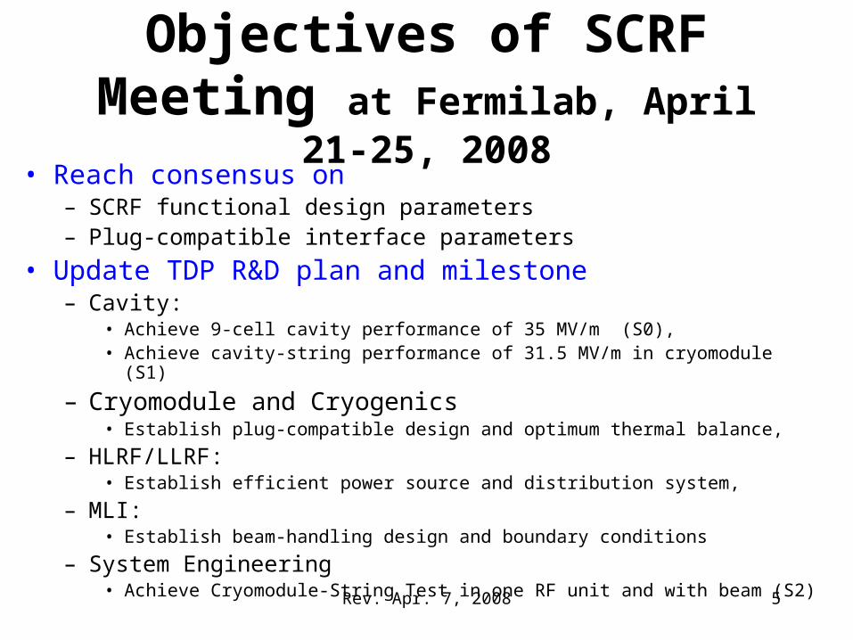
Objectives of SCRF Meeting at Fermilab, April 21-25, 2008
• Reach consensus on – SCRF functional design parameters– Plug-compatible interface parameters
• Update TDP R&D plan and milestone– Cavity:
• Achieve 9-cell cavity performance of 35 MV/m (S0), • Achieve cavity-string performance of 31.5 MV/m in cryomodule (S1)
– Cryomodule and Cryogenics• Establish plug-compatible design and optimum thermal balance,
– HLRF/LLRF: • Establish efficient power source and distribution system,
– MLI:• Establish beam-handling design and boundary conditions
– System Engineering• Achieve Cryomodule-String Test in one RF unit and with beam (S2) 5
Rev. Apr. 7, 2008
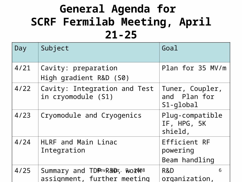
General Agenda for SCRF Fermilab Meeting, April 21-25
Day Subject Goal
4/21 Cavity: preparation
High gradient R&D (S0)
Plan for 35 MV/m
4/22 Cavity: Integration and Test in cryomodule (S1)
Tuner, Coupler, and Plan for S1-global
4/23 Cryomodule and Cryogenics Plug-compatible IF, HPG, 5K shield,
4/24 HLRF and Main Linac Integration Efficient RF powering
Beam handling
4/25 Summary and TDP R&D, work assignment, further meeting plan
R&D organization,
Interium review plan
6
Rev. Apr. 7, 2008
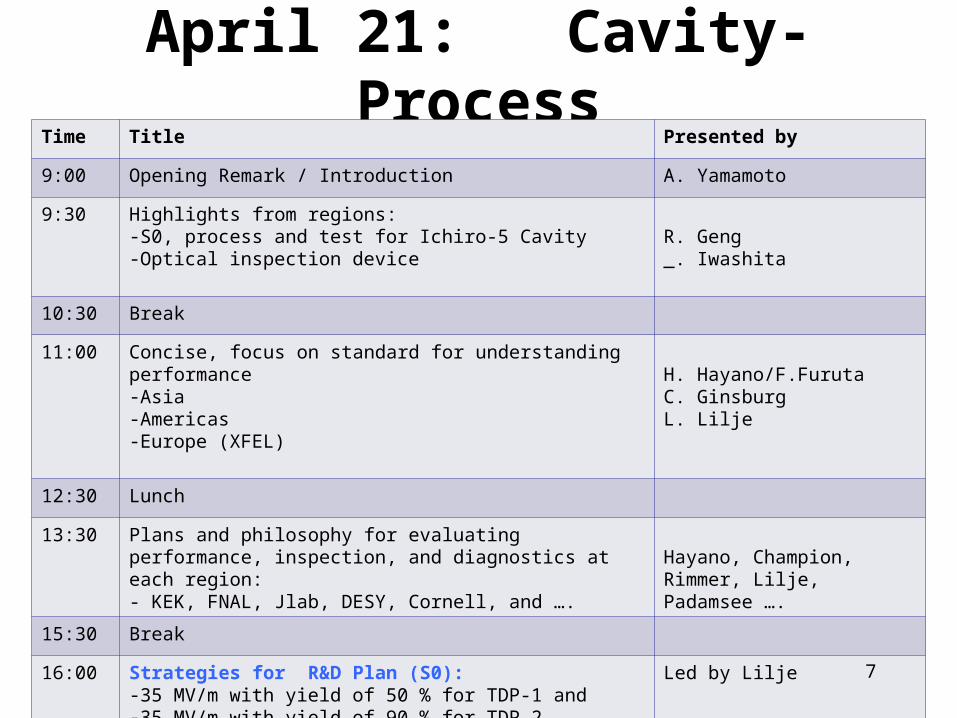
April 21: Cavity-ProcessTime Title Presented by
9:00 Opening Remark / Introduction A. Yamamoto
9:30 Highlights from regions:-S0, process and test for Ichiro-5 Cavity-Optical inspection device
R. Geng _. Iwashita
10:30 Break
11:00 Concise, focus on standard for understanding performance -Asia-Americas-Europe (XFEL)
H. Hayano/F.FurutaC. GinsburgL. Lilje
12:30 Lunch
13:30 Plans and philosophy for evaluating performance, inspection, and diagnostics at each region:- KEK, FNAL, Jlab, DESY, Cornell, and ….
Hayano, Champion, Rimmer, Lilje, Padamsee ….
15:30 Break
16:00 Strategies for R&D Plan (S0): -35 MV/m with yield of 50 % for TDP-1 and-35 MV/m with yield of 90 % for TDP-2
Led by Lilje
17:30 Comments H. Padamsee (AAP)7
Rev. Apr. 7, 2008
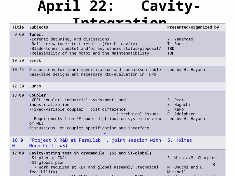
April 22: Cavity-IntegrationTitle Subjects Presented/organized by
9:00 Tuner:-Lorentz detuning, and discussions-Ball-screw-tuner test results (for LL cavity)-Blade-tuner (update) and/or any others status/proposal?-Relaiability of the motor and the Maintenatibility
Y. YamamotoT. SaekiTBDTBD
10:30 Break
10:45 Discussions for tuner specification and comparison tableBase-line designs and necessary R&D/evaluation in TDPs
Led by H. Hayano
12:30 Lunch
13:00 Coupler:-XFEL coupler: industrial assessment, and industrialization-Fixed/variable coupler : cost difference- : technical issues- Requirements from RF power distribution system in view of MLIDiscussions on coupler specification and interface
S. PratS. NoguchiE. KakoC. AdolphsenLed by H. Hayano
16;00 “Project X R&D at Fermilab” , joint session with Muon Coll. WS). S. Holmes
17:00 Cavity-string test in cryomodule (S1 and S1-global)-S1 plan at FNAL-S1-global plan - Work required at KEK and global assembly (technical feasibility) - Cooperation with FNAL / Cooperation with DESY
S. Mishra/M. Champion
N. Ohuchi and D. MitchellS. Mishra / L. Lilje
18:30 Comments H. Padamsee (AAP) 8
Rev. Apr. 7, 2008
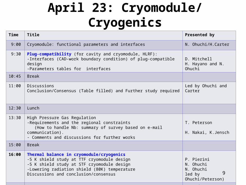
April 23: Cryomodule/ CryogenicsTime Title Presented by
9:00 Cryomodule: functional parameters and interfaces N. Ohuchi/H.Carter
9:30 Plug-compatibility (for cavity and cryomodule, HLRF):-Interfaces (CAD-work boundary condition) of plug-compatible design-Parameters tables for interfaces
D. MitchellH. Hayano and N. Ohuchi
10:45 Break
11:00 DiscussionsConclusion/Consensus (Table filled) and Further study required
Led by Ohuchi and Carter
12:30 Lunch
13:30 High Pressure Gas Regulation -Requirements and the regional constraints (How to handle Nb: summary of survey based on e-mail communication).- Comments and discussions for further works
T. Peterson
H. Nakai, K.Jensch
15:00 Break
16:00 Thermal balance in cryomodule/cryogenics-5 K shield study at TTF cryomodule design -5 K shield study at STF cryomodule design-Lowering radiation shield (80K) temperatureDiscussions and conclusion/consensus
P. PieriniN. OhuchiN. Ohuchiled by Ohuchi/Peterson)
17:30 Comments H. Padamsee (AAP)
9
Rev. Apr. 7, 2008
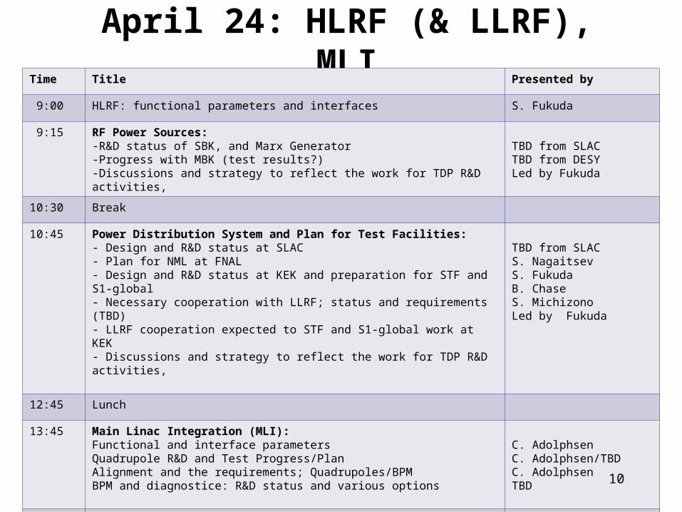
April 24: HLRF (& LLRF), MLITime Title Presented by
9:00 HLRF: functional parameters and interfaces S. Fukuda
9:15 RF Power Sources:-R&D status of SBK, and Marx Generator-Progress with MBK (test results?) -Discussions and strategy to reflect the work for TDP R&D activities,
TBD from SLACTBD from DESYLed by Fukuda
10:30 Break
10:45 Power Distribution System and Plan for Test Facilities:- Design and R&D status at SLAC- Plan for NML at FNAL- Design and R&D status at KEK and preparation for STF and S1-global- Necessary cooperation with LLRF; status and requirements (TBD)- LLRF cooperation expected to STF and S1-global work at KEK - Discussions and strategy to reflect the work for TDP R&D activities,
TBD from SLAC S. NagaitsevS. FukudaB. ChaseS. Michizono Led by Fukuda
12:45 Lunch
13:45 Main Linac Integration (MLI): Functional and interface parametersQuadrupole R&D and Test Progress/PlanAlignment and the requirements; Quadrupoles/BPMBPM and diagnostice: R&D status and various options
C. AdolphsenC. Adolphsen/TBDC. AdolphsenTBD
15:45 Break
16:00 Discussions and consensus for further R&D strategy, Led by Adolphsen
17:30 Comments H. Padamsee (AAP)10
Rev. Apr. 7, 2008
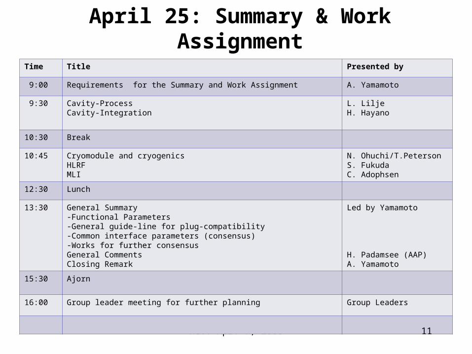
April 25: Summary & Work Assignment
Time Title Presented by
9:00 Requirements for the Summary and Work Assignment A. Yamamoto
9:30 Cavity-ProcessCavity-Integration
L. LiljeH. Hayano
10:30 Break
10:45 Cryomodule and cryogenicsHLRFMLI
N. Ohuchi/T.PetersonS. FukudaC. Adophsen
12:30 Lunch
13:30 General Summary-Functional Parameters-General guide-line for plug-compatibility-Common interface parameters (consensus)-Works for further consensusGeneral CommentsClosing Remark
Led by Yamamoto
H. Padamsee (AAP)A. Yamamoto
15:30 Ajorn
16:00 Group leader meeting for further planning Group Leaders
11
Rev. Apr. 7, 200812
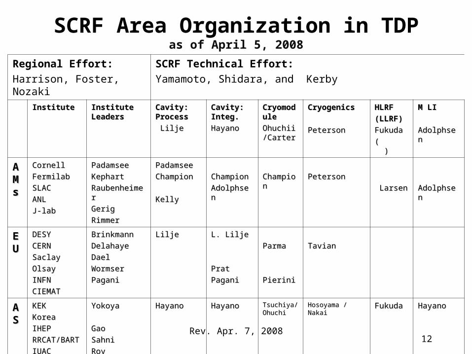
SCRF Area Organization in TDPas of April 5, 2008
Regional Effort:
Harrison, Foster, Nozaki
SCRF Technical Effort:
Yamamoto, Shidara, and Kerby
InstituteInstitute Institute Institute LeadersLeaders
Cavity: Cavity: ProcessProcess
LiljeLilje
Cavity: Cavity: Integ.Integ.
HayanoHayano
CryomodCryomoduleule
Ohuchii/Ohuchii/CarterCarter
CryogenicsCryogenics
PetersonPeterson
HLRFHLRF
(LLRF)(LLRF)
FukudaFukuda
( )( )
M LIM LI
AdolphsenAdolphsen
AAMMss
CornellCornell
FermilabFermilab
SLACSLAC
ANLANL
J-labJ-lab
PadamseePadamsee
KephartKephart
RaubenheimerRaubenheimer
GerigGerig
RimmerRimmer
PadamseePadamsee
ChampionChampion
KellyKelly
ChampionChampion
AdolphsenAdolphsen
ChampioChampionn
PetersonPeterson
LarsenLarsen AdolphsenAdolphsen
EEUU
DESYDESY
CERNCERN
SaclaySaclay
OlsayOlsay
INFNINFN
CIEMATCIEMAT
BrinkmannBrinkmann
DelahayeDelahaye
DaelDael
WormserWormser
PaganiPagani
LiljeLilje L. LiljeL. Lilje
PratPrat
PaganiPagani
ParmaParma
PieriniPierini
TavianTavian
AAS S
KEKKEK
KoreaKorea
IHEPIHEP
RRCAT/RRCAT/BARTBART
IUACIUAC
VECCVECC
YokoyaYokoya
GaoGao
SahniSahni
RoyRoy
BhandariBhandari
HayanoHayano HayanoHayano Tsuchiya/Tsuchiya/OhuchiOhuchi
Hosoyama / Hosoyama / NakaiNakai
FukudaFukuda HayanoHayano
Rev. Apr. 7, 2008
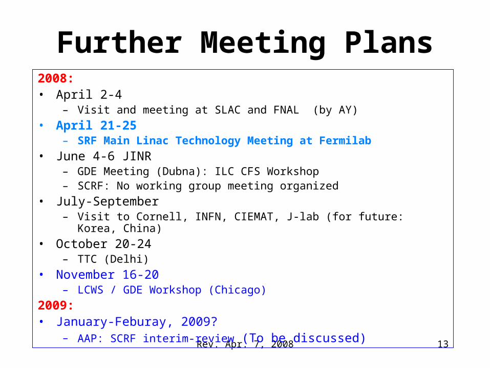
Further Meeting Plans2008:• April 2-4
– Visit and meeting at SLAC and FNAL (by AY)
• April 21-25 – SRF Main Linac Technology Meeting at Fermilab
• June 4-6 JINR– GDE Meeting (Dubna): ILC CFS Workshop– SCRF: No working group meeting organized
• July-September – Visit to Cornell, INFN, CIEMAT, J-lab (for future: Korea, China)
• October 20-24– TTC (Delhi)
• November 16-20– LCWS / GDE Workshop (Chicago)
2009:• January-Feburay, 2009?
– AAP: SCRF interim-review (To be discussed) 13
Rev. Apr. 7, 2008
Backup
14
Rev. Apr. 7, 2008
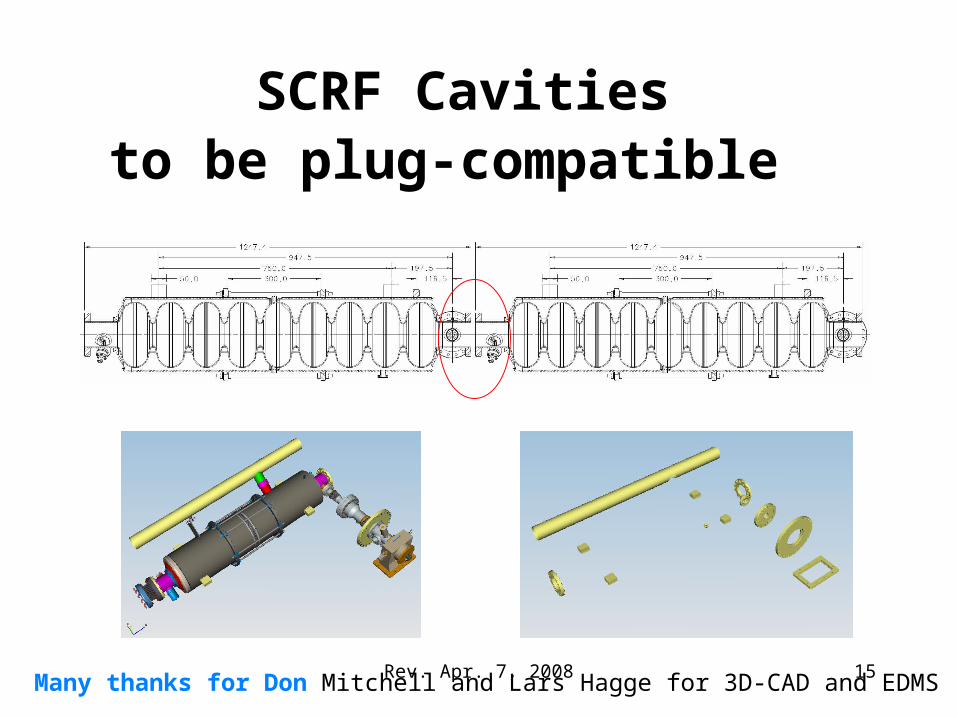
SCRF Cavities to be plug-compatible
Many thanks for Don Mitchell and Lars Hagge for 3D-CAD and EDMS 15
Rev. Apr. 7, 2008
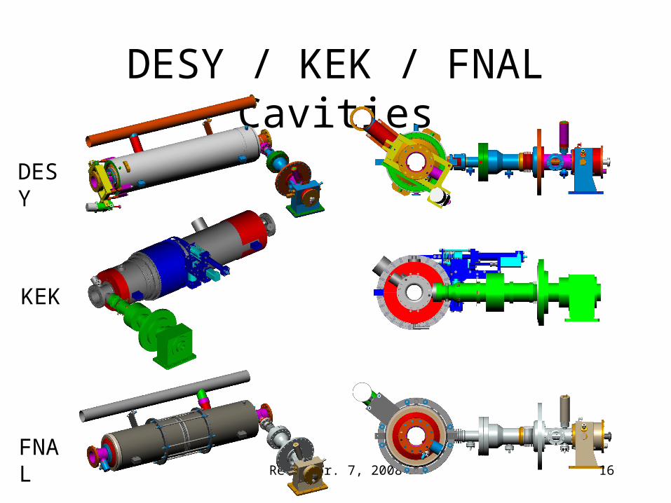
DESY / KEK / FNAL Cavities
DESY
KEK
FNAL 16
Rev. Apr. 7, 2008
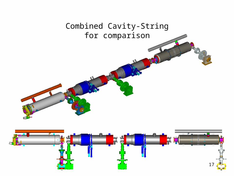
Combined Cavity-Stringfor comparison
DESY
FNAL
KEK
KEK 17
Rev. Apr. 7, 2008
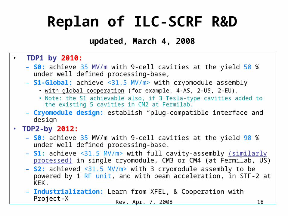
Replan of ILC-SCRF R&D updated, March 4, 2008
• TDP1 by 2010:– S0: achieve 35 MV/m with 9-cell cavities at the yield 50 % under well
defined processing-base,– S1-Global: achieve <31.5 MV/m> with cryomodule-assembly
• with global cooperation (for example, 4-AS, 2-US, 2-EU). • Note: the S1 achievable also, if 3 Tesla-type cavities added to the existing 5
cavities in CM2 at Fermilab.
– Cryomodule design: establish “plug-compatible interface and design
• TDP2-by 2012:– S0: achieve 35 MV/m with 9-cell cavities at the yield 90 % under well
defined processing-base.– S1: achieve <31.5 MV/m> with full cavity-assembly (similarly processed)
in single cryomodule, CM3 or CM4 (at Fermilab, US)– S2: achieved <31.5 MV/m> with 3 cryomodule assembly to be powered by
1 RF unit, and with beam acceleration, in STF-2 at KEK.– Industrialization: Learn from XFEL, & Cooperation with Project-X
18
Rev. Apr. 7, 2008
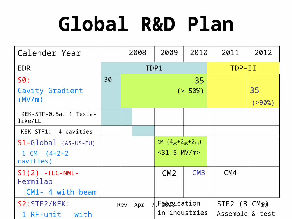
Global R&D PlanCalender Year 2008 2009 2010 2011 2012
EDR TDP1 TDP-II
S0:
Cavity Gradient (MV/m)
30 35 (> 50%)
35
(>90%) KEK-STF-0.5a: 1 Tesla-like/LL
KEK-STF1: 4 cavities
S1-Global (AS-US-EU)
1 CM (4+2+2 cavities)
CM (4AS+2US+2EU)
<31.5 MV/m>
S1(2) -ILC-NML-Fermilab
CM1- 4 with beam CM2 CM3 CM4
S2:STF2/KEK:
1 RF-unit with beam
Fabrication
in industriesSTF2 (3 CMs)Assemble & test
19
Rev. Apr. 7, 2008
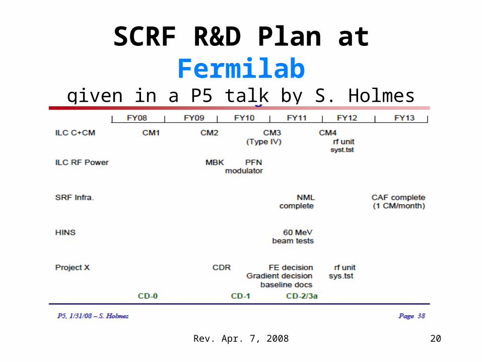
SCRF R&D Plan at Fermilabgiven in a P5 talk by S. Holmes
20
Rev. Apr. 7, 2008
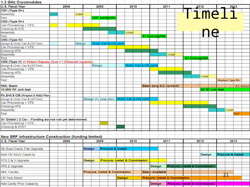
Timeline
21
Rev. Apr. 7, 2008 22
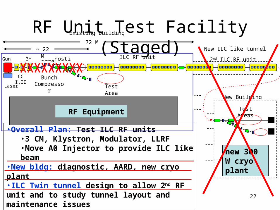
•Overall Plan: Test ILC RF units•3 CM, Klystron, Modulator, LLRF•Move A0 Injector to provide ILC like beam
•New bldg: diagnostic, AARD, new cryo plant•ILC Twin tunnel design to allow 2nd RF unit and to study tunnel layout and maintenance issues
Bunch Compressor
ILC RF unitDiagnosticsGun
CC I,II
Laser
3rd har
Test Area
~ 22 M72 M
Existing Building
New Building
New ILC like tunnel
2nd ILC RF unit
Test Areas
new 300 W cryo plant
RF Equipment
RF Unit Test Facility (Staged)
Rev. Apr. 7, 2008
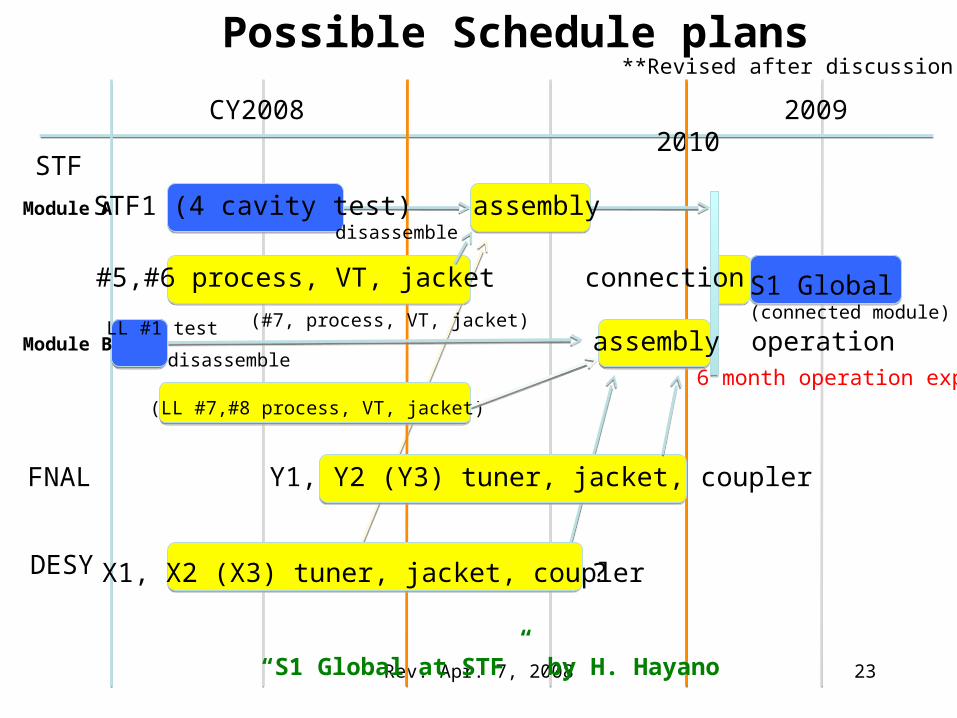
CY2008 2009 2010
STF
FNAL
S1 Global (connected module)
Possible Schedule plans
Y1, Y2 (Y3) tuner, jacket, coupler
DESY X1, X2 (X3) tuner, jacket, coupler
Module A
Module B
#5,#6 process, VT, jacket
(LL #7,#8 process, VT, jacket)
operation
assembly
assembly
connection
STF1 (4 cavity test)
LL #1 test
disassemble
disassemble
6 month operation exp.
(#7, process, VT, jacket)
?
“S1 Global at STF” by H. Hayano
**Revised after discussion
23
Rev. Apr. 7, 2008
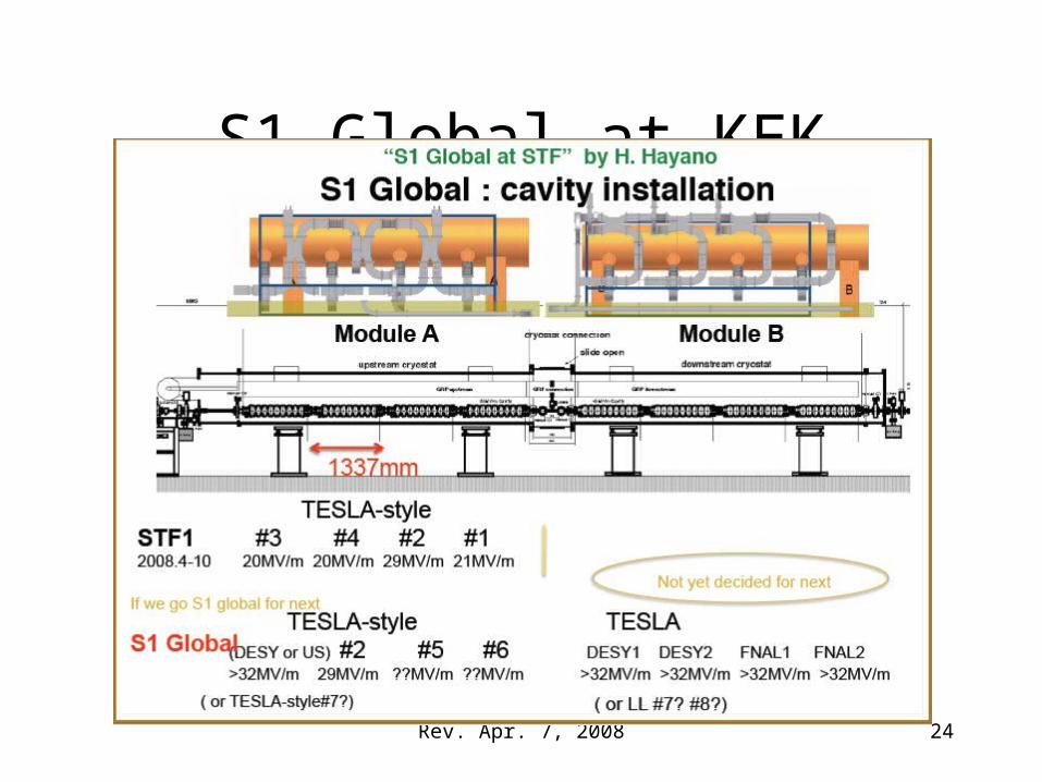
S1 Global at KEK
24
Rev. Apr. 7, 2008
Progress in the GDE Tohoku Meeting
and Further Studies expected
25
Rev. Apr. 7, 2008
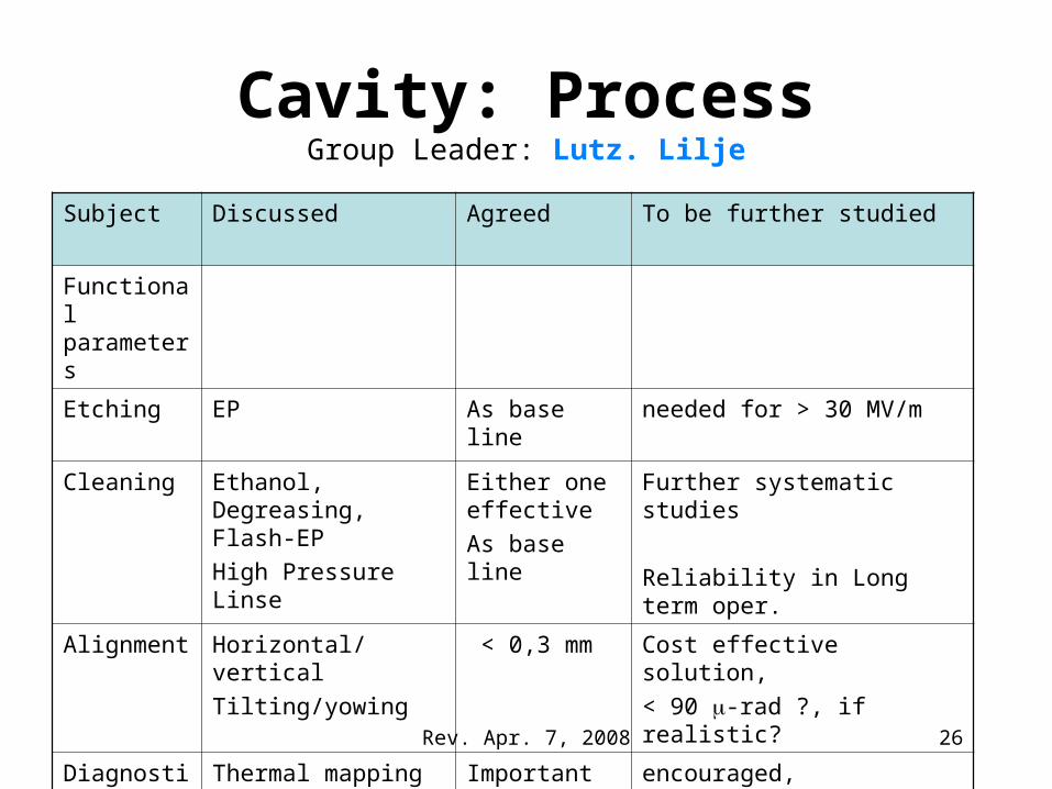
Cavity: ProcessGroup Leader: Lutz. Lilje
Subject Discussed Agreed To be further studied
Functional parameters
Etching EP As base line needed for > 30 MV/m
Cleaning Ethanol, Degreasing, Flash-EP
High Pressure Linse
Either one effective
As base line
Further systematic studies
Reliability in Long term oper.
Alignment Horizontal/vertical
Tilting/yowing
< 0,3 mm Cost effective solution,
< 90 -rad ?, if realistic?
Diagnostics Thermal mapping
Optical inspection
Important
important
encouraged,
World-wide use recommended
Material Grain-size/single-crystal
Important for understanding
Basic study to be extended for future possibility for simple process and cost redcuion 26
Rev. Apr. 7, 2008
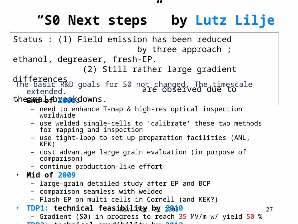
“S0 Next steps” by Lutz LiljeStatus : (1) Field emission has been reduced by three approach ; ethanol, degreaser, fresh-EP. (2) Still rather large gradient differences are observed due to thermal breakdowns.
The basic R&D goals for S0 not changed. The timescale extended.• End of 2008:
– need to enhance T-map & high-res optical inspection worldwide– use welded single-cells to 'calibrate' these two methods for mapping and
inspection– use tight-loop to set up preparation facilities (ANL, KEK)– cost advantage large grain evaluation (in purpose of comparison)– continue production-like effort
• Mid of 2009– large-grain detailed study after EP and BCP– comparison seamless with welded– Flash EP on multi-cells in Cornell (and KEK?)
• TDP1: technical feasibility by 2010– Gradient (S0) in progress to reach 35 MV/m w/ yield 50 %
• TDP2: technical credibility by 2012– Gradient (S0) to reach 35 MV/m w/ yield 90 % 27
Rev. Apr. 7, 2008
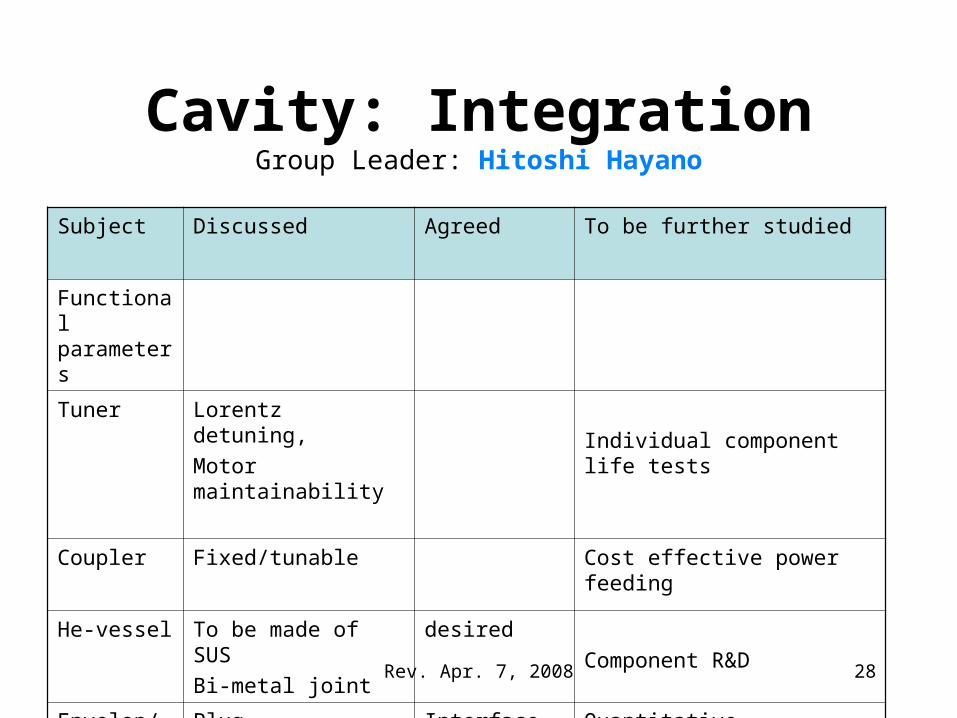
Cavity: IntegrationGroup Leader: Hitoshi Hayano
Subject Discussed Agreed To be further studied
Functional parameters
Tuner Lorentz detuning,
Motor maintainability Individual component life tests
Coupler Fixed/tunable Cost effective power feeding
He-vessel To be made of SUS
Bi-metal joint
desired
Component R&D
Envelop/Interface
Plug-compatibility Interface components
Quantitative conditions,
28
Rev. Apr. 7, 2008
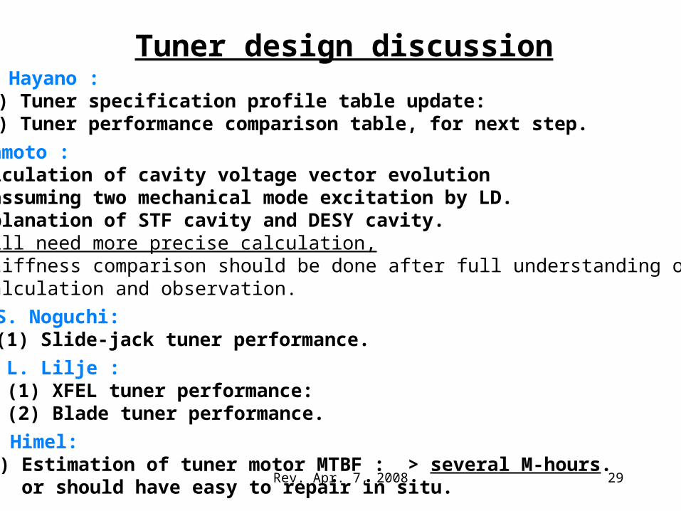
Tuner design discussionH. Hayano : (1) Tuner specification profile table update: (2) Tuner performance comparison table, for next step.
Y. Yamamoto : (1) Calculation of cavity voltage vector evolution assuming two mechanical mode excitation by LD. (2) Explanation of STF cavity and DESY cavity. -> still need more precise calculation, stiffness comparison should be done after full understanding of calculation and observation.
S. Noguchi: (1) Slide-jack tuner performance.
L. Lilje : (1) XFEL tuner performance: (2) Blade tuner performance.
T. Himel: (1) Estimation of tuner motor MTBF : > several M-hours. or should have easy to repair in situ.
29
Rev. Apr. 7, 2008
Coupler design discussion
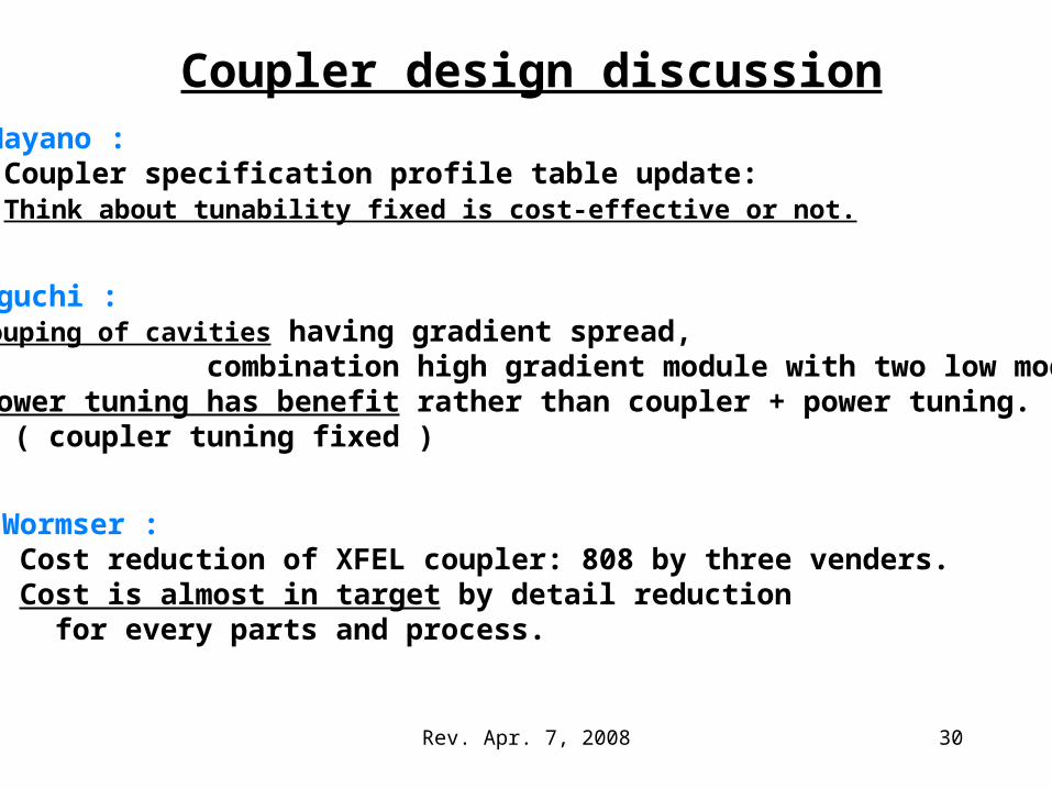
S. Noguchi : (1)Grouping of cavities having gradient spread, combination high gradient module with two low modules.(2) Power tuning has benefit rather than coupler + power tuning. ( coupler tuning fixed )
G. Wormser : (1) Cost reduction of XFEL coupler: 808 by three venders. (2) Cost is almost in target by detail reduction for every parts and process.
H. Hayano : (1) Coupler specification profile table update: (2) Think about tunability fixed is cost-effective or not.
30
Rev. Apr. 7, 2008
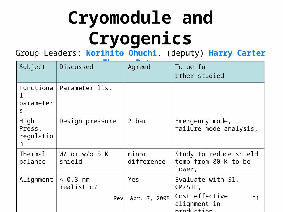
Cryomodule and CryogenicsGroup Leaders: Norihito Ohuchi, (deputy) Harry Carter
Thomas Peterson
Subject Discussed Agreed To be fu
rther studied
Functional parameters
Parameter list
High Press. regulation
Design pressure 2 bar Emergency mode, failure mode analysis,
Thermal balance
W/ or w/o 5 K shield minor difference
Study to reduce shield temp from 80 K to be lower,
Alignment < 0.3 mm realistic? Yes Evaluate with S1, CM/STF,
Cost effective alignment in production,
Envelope/interface
Interface components
EDMS work
Vac. Ch. Diameter
List-up
No change
CAD design work for compatibility b/w ILC & others
31
Rev. Apr. 7, 2008
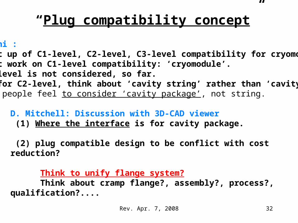
“Plug compatibility concept”
D. Mitchell: Discussion with 3D-CAD viewer (1) Where the interface is for cavity package. (2) plug compatible design to be conflict with cost reduction?
Think to unify flange system? Think about cramp flange?, assembly?, process?, qualification?....
N. Ohuchi : (1) List up of C1-level, C2-level, C3-level compatibility for cryomodule. (2) Must work on C1-level compatibility: ‘cryomodule’.(3) C3-level is not considered, so far.(4) As for C2-level, think about ‘cavity string’ rather than ‘cavity package’ -> people feel to consider ‘cavity package’, not string.
32
Rev. Apr. 7, 2008
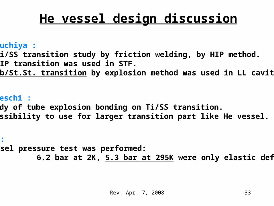
He vessel design discussion
K. Tsuchiya : (1) Ti/SS transition study by friction welding, by HIP method.(2) HIP transition was used in STF. (3) Nb/St.St. transition by explosion method was used in LL cavity.
F. Bedeschi : (1)Study of tube explosion bonding on Ti/SS transition.(2) Possibility to use for larger transition part like He vessel.
L. Lilje : (1)He vessel pressure test was performed: 6.2 bar at 2K, 5.3 bar at 295K were only elastic deformation.
33
Rev. Apr. 7, 2008
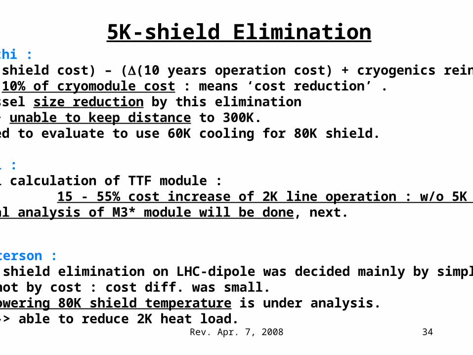
5K-shield EliminationN. Ohuchi : (1)(5K shield cost) – ((10 years operation cost) + cryogenics reinforce) = 10% of cryomodule cost : means ‘cost reduction’ .(2) Vessel size reduction by this elimination -> unable to keep distance to 300K.(3) Need to evaluate to use 60K cooling for 80K shield.
P. Pierini : (1)Thermal calculation of TTF module : 15 - 55% cost increase of 2K line operation : w/o 5K shield.(2) Thermal analysis of M3* module will be done, next.
T. Peterson : (1)5K shield elimination on LHC-dipole was decided mainly by simplicity, not by cost : cost diff. was small.(2) Lowering 80K shield temperature is under analysis. -> able to reduce 2K heat load.
34
Rev. Apr. 7, 2008
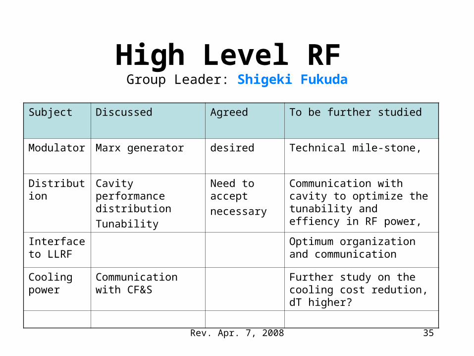
High Level RF Group Leader: Shigeki Fukuda
Subject Discussed Agreed To be further studied
Modulator Marx generator desired Technical mile-stone,
Distribution Cavity performance distribution
Tunability
Need to accept
necessary
Communication with cavity to optimize the tunability and effiency in RF power,
Interface to LLRF
Optimum organization and communication
Cooling power
Communication with CF&S
Further study on the cooling cost redution, dT higher?
35
Rev. Apr. 7, 2008
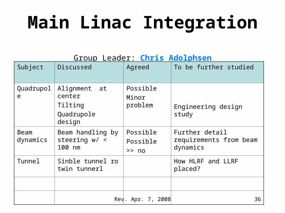
Main Linac Integration Group Leader: Chris Adolphsen
Subject Discussed Agreed To be further studied
Quadrupole Alignment at center
Tilting
Quadrupole design
Possible
Minor problem
Engineering design study
Beam dynamics
Beam handling by steering w/ < 100 nm
Possible
Possible
>> no
Further detail requirements from beam dynamics
Tunnel Sinble tunnel ro twin tunnerl
How HLRF and LLRF placed?
36
Rev. Apr. 7, 2008
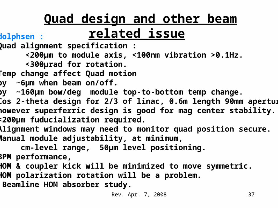
Quad design and other beam related issueC. Adolphsen : (1) Quad alignment specification : <200µm to module axis, <100nm vibration >0.1Hz. <300µrad for rotation. (2) Temp change affect Quad motion by ~6µm when beam on/off. by ~160µm bow/deg module top-to-bottom temp change.(3) Cos 2-theta design for 2/3 of linac, 0.6m length 90mm aperture. however superferric design is good for mag center stability.(4) <200µm fuducialization required.(5) Alignment windows may need to monitor quad position secure.(6) Manual module adjustability, at minimum, cm-level range, 50µm level positioning.(7) BPM performance,(8) HOM & coupler kick will be minimized to move symmetric.(9) HOM polarization rotation will be a problem.(10) Beamline HOM absorber study. …. 37
Rev. Apr. 7, 2008
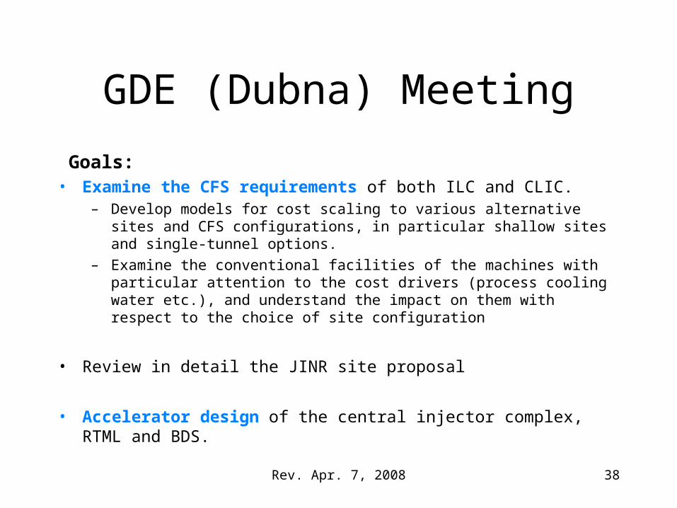
GDE (Dubna) Meeting
Goals:• Examine the CFS requirements of both ILC and CLIC.
– Develop models for cost scaling to various alternative sites and CFS configurations, in particular shallow sites and single-tunnel options.
– Examine the conventional facilities of the machines with particular attention to the cost drivers (process cooling water etc.), and understand the impact on them with respect to the choice of site configuration
• Review in detail the JINR site proposal
• Accelerator design of the central injector complex, RTML and BDS.
38
Rev. Apr. 7, 2008
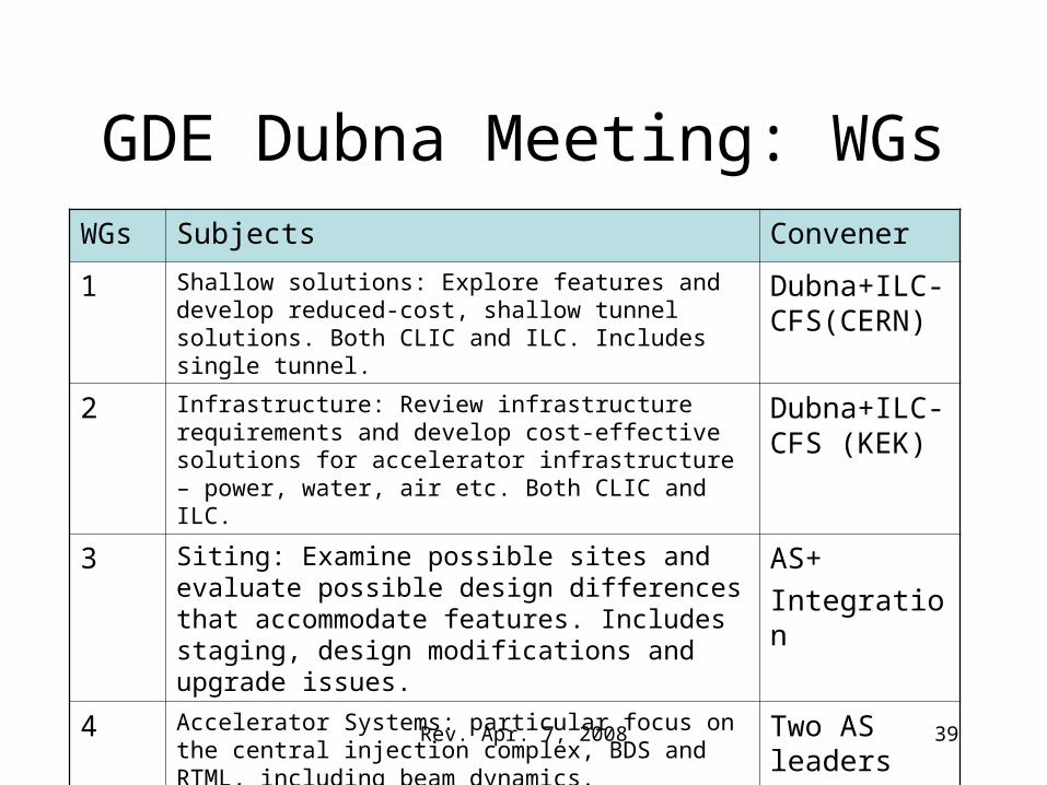
GDE Dubna Meeting: WGs WGs Subjects Convener
1 Shallow solutions: Explore features and develop reduced-cost, shallow tunnel solutions. Both CLIC and ILC. Includes single tunnel.
Dubna+ILC-CFS(CERN)
2 Infrastructure: Review infrastructure requirements and develop cost-effective solutions for accelerator infrastructure – power, water, air etc. Both CLIC and ILC.
Dubna+ILC-CFS (KEK)
3 Siting: Examine possible sites and evaluate possible design differences that accommodate features. Includes staging, design modifications and upgrade issues.
AS+
Integration
4 Accelerator Systems: particular focus on the central injection complex, BDS and RTML, including beam dynamics.
Two AS leaders
39