Embed Size (px)
Citation preview
UK HPR1000
GDA
Pre-Construction Safety Report Chapter 10 Auxiliary Systems
UK Protective Marking: Not Protectively Marked
Rev: 001 Page: II
UK Protective Marking: Not Protectively Marked
DISTRIBUTION LIST
Recipients Cross Box
General Nuclear System Executive ☐
General Nuclear System all staff ☐
General Nuclear System and BRB all staff ☒
CGN ☒
EDF ☒
Regulators ☒
Public ☒
UK HPR1000
GDA
Pre-Construction Safety Report Chapter 10 Auxiliary Systems
UK Protective Marking: Not Protectively Marked
Rev: 001 Page: 1 / 504
UK Protective Marking: Not Protectively Marked
TABLE OF CONTENTS
10.1 List of Abbreviations and Acronyms .................................................................. 5
10.2 Introduction ........................................................................................................ 11
10.2.1 Chapter Route Map ................................................................................................ 11
10.2.2 Chapter Structure ................................................................................................... 11
10.2.3 Interface with Other Chapters ............................................................................... 12
10.2.4 General Design Requirements .............................................................................. 17
10.3 Heavy Load Lifting Systems ............................................................................. 32
10.3.1 Sub-chapter Structure ........................................................................................... 32
10.3.2 Applicable Codes and Standards ........................................................................... 32
10.3.3 Reactor Building Handling Equipment (DMR [RBHE]) ...................................... 33
10.3.4 Fuel Building Handling Equipment (DMK [FBHE]) ........................................... 42
10.3.5 ALARP Assessment .............................................................................................. 51
10.3.6 Concluding Remarks............................................................................................. 52
10.4 Nuclear Auxiliary Systems ................................................................................ 53
10.4.1 Sub-chapter Structure ........................................................................................... 53
10.4.2 Applicable Codes and Standards ........................................................................... 53
10.4.3 Chemical and Volume Control System (RCV [CVCS]) ....................................... 54
10.4.4 Reactor Boron and Water Makeup System (REA [RBWMS]) ............................. 75
10.4.5 Coolant Storage and Treatment System (TEP [CSTS]) ........................................ 92
10.4.6 Nuclear Sampling System (REN [NSS]) ............................................................ 105
10.4.7 Fuel Pool Cooling and Treatment System (PTR [FPCTS]) ................................ 121
10.4.8 Component Cooling Water System (RRI [CCWS])............................................ 139
10.4.9 Essential Service Water System (SEC [ESWS]) ................................................. 155
10.4.10 ALARP Assessment .......................................................................................... 167
10.4.11 Concluding Remarks ......................................................................................... 169
UK HPR1000
GDA
Pre-Construction Safety Report Chapter 10 Auxiliary Systems
UK Protective Marking: Not Protectively Marked
Rev: 001 Page: 2 / 504
UK Protective Marking: Not Protectively Marked
10.4.12 Simplified Diagrams ......................................................................................... 169
10.5 Process Auxiliary Systems ............................................................................... 180
10.5.1 Sub-chapter Structure ......................................................................................... 180
10.5.2 Applicable Codes and Standards ......................................................................... 180
10.5.3 NI Demineralised Water Distribution System (SED [DWDS (NI)]) .................. 181
10.5.4 Nuclear Island Potable Water System (SEP [PWS (NI)]) ................................... 187
10.5.5 Nuclear Island Gas Distribution Systems (SGO [ODS], SGN [NDS], SGH [HDS
(NI)]) .............................................................................................................................. 189
10.5.6 Compressed Air Distribution Systems (SAP [CAPS], SAR [ICADS] SAT [SCADS])
....................................................................................................................................... 192
10.5.7 ALARP Assessment ............................................................................................ 195
10.5.8 Concluding Remarks........................................................................................... 196
10.6 Heating, Ventilation and Air Conditioning (HVAC) Systems ...................... 196
10.6.1 Sub-chapter Structure ......................................................................................... 196
10.6.2 Applicable Codes and Standards ......................................................................... 197
10.6.3 Nuclear Auxiliary Building Ventilation System (DWN [NABVS]) ................... 198
10.6.4 Fuel Building Ventilation System (DWK [FBVS]) ............................................ 212
10.6.5 Containment Cooling and Ventilation System (EVR [CCVS]) .......................... 227
10.6.6 Containment Internal Filtration System (EVF [CIFS]) ...................................... 236
10.6.7 Containment Sweeping and Blowdown Ventilation System (EBA [CSBVS]) ... 245
10.6.8 Annulus Ventilation System (EDE [AVS]) ......................................................... 258
10.6.9 Safeguard Building Controlled Area Ventilation System (DWL [SBCAVS]) .... 271
10.6.10 Electrical Division of Safeguard Building Ventilation System (DVL [EDSBVS])
....................................................................................................................................... 291
10.6.11 Main Control Room Air Conditioning System (DCL [MCRACS]).................. 302
10.6.12 Access Building Ventilation Systems (DVW [ABUAVS]-DWW [ABCAVS]) 313
10.6.13 Diesel Building Ventilation System (DVD [DBVS]) ....................................... 322
10.6.14 Essential Service Water Pumping Station Ventilation System (DXS [ESWVS])
UK HPR1000
GDA
Pre-Construction Safety Report Chapter 10 Auxiliary Systems
UK Protective Marking: Not Protectively Marked
Rev: 001 Page: 3 / 504
UK Protective Marking: Not Protectively Marked
....................................................................................................................................... 333
10.6.15 Extra Cooling Water and NI Firefighting Building Ventilation System (DXE
[ECW&FFB VS]) .......................................................................................................... 340
10.6.16 Waste Treatment Building Ventilation System (DWQ [WTBVS]) ................... 348
10.6.17 Safety Chilled Water System (DEL [SCWS]) ................................................... 363
10.6.18 Operational Chilled Water System (DER [OCWS]) ......................................... 373
10.6.19 ALARP Assessment .......................................................................................... 381
10.6.20 Concluding Remarks......................................................................................... 383
10.6.21 Simplified Diagrams ......................................................................................... 383
10.6.22 Tables of Design Assumptions .......................................................................... 400
10.7 Fire Protection Systems ................................................................................... 412
10.7.1 Sub-chapter Structure ...................................................................................... 412
10.7.2 Applicable Codes and Standards ..................................................................... 412
10.7.3 Fire Alarm System ........................................................................................... 413
10.7.4 Fire-fighting Systems ....................................................................................... 422
10.7.5 Smoke Control System (DFL [SCS]) .............................................................. 440
10.7.6 ALARP Assessment ......................................................................................... 449
10.7.7 Concluding Remarks ....................................................................................... 450
10.7.8 Simplified Diagrams ........................................................................................ 451
10.8 Diesel Generators ............................................................................................. 456
10.8.1 Sub-chapter Structure ......................................................................................... 456
10.8.2 Applicable Codes and Standards ......................................................................... 456
10.8.3 Emergency Diesel Generator .............................................................................. 458
10.8.4 SBO Diesel Generator ........................................................................................ 466
10.8.5 ALARP Assessment ............................................................................................ 474
10.8.6 Concluding Remarks........................................................................................... 475
10.8.7 Simplified Diagrams ........................................................................................... 475
10.9 Concluding Remarks ....................................................................................... 478

UK HPR1000
GDA
Pre-Construction Safety Report Chapter 10 Auxiliary Systems
UK Protective Marking: Not Protectively Marked
Rev: 001 Page: 4 / 504
UK Protective Marking: Not Protectively Marked
10.10 References ....................................................................................................... 479
Appendix 10A Route Map of Sub-Chapter 10.3 ................................................... 494
Appendix 10B Route Map of Sub-Chapter 10.4 ................................................... 496
Appendix 10C Route Map of Sub-Chapter 10.6 ................................................... 498
Appendix 10D Route Map of Sub-Chapter 10.7 ................................................... 500
Appendix 10E Route Map of Sub-Chapter 10.8 ................................................... 502
UK HPR1000
GDA
Pre-Construction Safety Report Chapter 10 Auxiliary Systems
UK Protective Marking: Not Protectively Marked
Rev: 001 Page: 5 / 504
UK Protective Marking: Not Protectively Marked
10.1 List of Abbreviations and Acronyms
AFFF Aqueous Film-forming Foam
ALARP As Low As Reasonably Practicable
APG Steam Generator Blowdown System [SGBS]
ASP Secondary Passive Heat Removal System [SPHRS]
ATWS Anticipated Transient Without Scram
BPX Personnel Access Building
BDX Diesel Generator Buildings
BEJ Extra Cooling System and Fire-fighting System Building
BFX Fuel Building
BGA Essential Service Water Supply Gallery A
BGB Essential Service Water Supply Gallery B
BGC Essential Service Water Supply Gallery C
BNX Nuclear Auxiliary Building
BOP Balance of Plant
BPA Essential Service Water Pump Station A
BPB Essential Service Water Pump Station B
BRX Reactor Building
BSA Safeguard Building A
BSB Safeguard Building B
BSC Safeguard Building C
BSX Safeguard Buildings
BWX Radioactive Waste Treatment Building
CCF Common Cause Failure
CGN China General Nuclear Power Corporation
CRDM Control Rod Drive Mechanism
CTE Circulating Water Treatment System [CWTS]
DBC Design Basis Condition
UK HPR1000
GDA
Pre-Construction Safety Report Chapter 10 Auxiliary Systems
UK Protective Marking: Not Protectively Marked
Rev: 001 Page: 6 / 504
UK Protective Marking: Not Protectively Marked
DCL Main Control Room Air Conditioning System [MCRACS]
DEC Design Extension Condition
DEL Safety Chilled Water System [SCWS]
DEQ Waste Treatment Building Chilled water System [WTBCWS]
DER Operational Chilled Water System [OCWS]
DFL Smoke Control System [SCS]
DG Diesel Generator
DiD Defence in Depth
DMK Fuel Building Handling Equipment [FBHE]
DMR Reactor Building Handling Equipment [RBHE]
DVD Diesel Building Ventilation System [DBVS]
DVL Electrical Division of Safeguard Building Ventilation System [EDSBVS]
DVW Access Building Uncontrolled Area Ventilation System [ABUAVS]
DWK Fuel Building Ventilation System [FBVS]
DWL Safeguard Building Controlled Area Ventilation System [SBCAVS]
DWN Nuclear Auxiliary Building Ventilation System [NABVS]
DWQ Waste Treatment Building Ventilation System [WTBVS]
DWW Access Building Controlled Area Ventilation System [ABCAVS]
DXE Extra Cooling Water and NI Firefighting Building Ventilation System [ECW&FFB VS]
DXS Essential Service Water Pumping Station Ventilation System [ESWVS]
EBA Containment Sweeping and Blowndown Ventilation System [CSBVS]
ECS Extra Cooling System [ECS]
EDE Annulus Ventilation System [AVS]
UK HPR1000
GDA
Pre-Construction Safety Report Chapter 10 Auxiliary Systems
UK Protective Marking: Not Protectively Marked
Rev: 001 Page: 7 / 504
UK Protective Marking: Not Protectively Marked
EDG Emergency Diesel Generator
EHR Containment Heat Removal System [CHRS]
EMIT Examination, Maintenance, Inspection and Testing
EPP Containment Leak Rate Testing and Monitoring System [CLRTMS]
EPW Explosion Pressure Wave
EUF Containment Filtration and Exhaust System [CFES]
EVF Containment Internal Filtration System [CIFS]
EVR Containment Cooling and Ventilation System [CCVS]
GDA Generic Design Assessment
HBSC Human Based Safety Claims
HEPA High Efficiency Particulate Air
HFE Human Factors Engineering
HVAC Heating, Ventilation and Air Conditioning
I&C Instrumentation and Control
IRWST In-Containment Refuelling Water Storage Tank
IVR In-Vessel Retention
JAC Fire-fighting Water Production System [FWPS]
JDT Fire Alarm System [FAS]
JPI Fire-fighting Water System for Nuclear Island [NIFPS]
JPV Fire Extinguishing System for Nuclear Island Diesel Generator Building [FSDB]
KRH Nuclear Island Hydrogen Detection System [HDS]
KRT Plant Radiation Monitoring System [PRMS]
LHSI Low Head Safety Injection
LOCA Loss of Coolant Accident
LOOP Loss of Offsite Power
LUHS Loss of Ultimate Heat Sink
MCR Main Control Room
UK HPR1000
GDA
Pre-Construction Safety Report Chapter 10 Auxiliary Systems
UK Protective Marking: Not Protectively Marked
Rev: 001 Page: 8 / 504
UK Protective Marking: Not Protectively Marked
ME Mechanical Engineering
NDT Non-Destructive Testing
NI Nuclear Island
NPP Nuclear Power Plant
ONR Office for Nuclear Regulation (UK)
OPEX Operating Experience
PCSR Pre-Construction Environmental Report
PCSR Pre-Construction Safety Report
PLC Programmable Logic Controller
PSA Probabilistic Safety Assessment
PTR Fuel Pool Cooling and Treatment System [FPCTS]
PWR Pressurised Water Reactor
RBS Emergency Boration System [EBS]
RCC-M Design and Construction Rules for Mechanical Components of PWR Nuclear Islands
RCD Reactor Completely Discharge
RCP Reactor Coolant System [RCS]
RCPB Reactor Coolant Pressure Boundary
RCV Chemical and Volume Control System [CVCS]
REA Reactor Boron and Water Makeup System [RBWMS]
REN Nuclear Sampling System [NSS]
RGP Relevant Good Practice
RHR Residual Heat Removal
RIS Safety Injection System [SIS]
RPE Nuclear Island Vent and Drain System [VDS]
RPV Reactor Pressure Vessel
RRI Component Cooling Water System [CCWS]
RSS Remote Shutdown Station
UK HPR1000
GDA
Pre-Construction Safety Report Chapter 10 Auxiliary Systems
UK Protective Marking: Not Protectively Marked
Rev: 001 Page: 9 / 504
UK Protective Marking: Not Protectively Marked
SA Severe Accident
SAP Compressed Air Production System [CAPS]
SAR Instrument Compressed Air Distribution System [ICADS]
SAT Service Compressed Air Distribution System [SCADS]
SBD Radioactive Decontamination System [RDS]
SBE Hot Laundry System [HLS]
SBO Station Black Out
SDA Demineralised Water Production System [DWPS]
SDM System Design Manual
SEC Essential Service Water System [ESWS]
SED NI Demineralised Water Distribution System [DWDS (NI)]
SEO Station Sewer System [SSS]
SEP Potable Water System [PWS (NI)]
SES Hot Water Production and Distribution System [HWPDS]
SFC Single Failure Criterion
SFP Spent Fuel Pool
SG Steam Generator
SGH NI Hydrogen Distribution System [HDS (NI)]
SGN Nitrogen Distribution System [NDS]
SGO Oxygen Distribution System [ODS]
SGTR Steam Generator Tube Rupture
SI Safety Injection
SSC Structures, Systems and Components
SSE Safe Shutdown Earthquake
TEG Gaseous Waste Treatment System [GWTS]
TEP Coolant Storage and Treatment System [CSTS]
TER Nuclear Island Liquid Waste Discharge System [NLWDS]
TES Solid Waste Treatment System [SWTS]
UK HPR1000
GDA
Pre-Construction Safety Report Chapter 10 Auxiliary Systems
UK Protective Marking: Not Protectively Marked
Rev: 001 Page: 10 / 504
UK Protective Marking: Not Protectively Marked
TEU Liquid Waste Treatment System [LWTS]
TLOCC Total Loss of Cooling Chain
UK HPR1000 UK version of the Hua-long Pressurised Reactor
VCT Volume Control Tank
VDA Atmospheric Steam Dump System [ASDS]
VVP Main Steam System [MSS]
XCA Auxiliary Steam Production System [ASPS]
System codes (XXX) and system abbreviations (YYY) are provided for completeness in the format (XXX [YYY]), e.g. Chemical and Volume Control System (RCV [CVCS]).
UK HPR1000
GDA
Pre-Construction Safety Report Chapter 10 Auxiliary Systems
UK Protective Marking: Not Protectively Marked
Rev: 001 Page: 11 / 504
UK Protective Marking: Not Protectively Marked
10.2 Introduction
The purpose of Pre-Construction Safety Report (PCSR) Chapter 10 is to provide design information and engineering substantiation of the design of Auxiliary Systems for the UK version of the Hua-long Pressurised Reactor (UK HPR1000). The auxiliary systems presented in this chapter include the Heavy Load Lifting Systems, the Nuclear Auxiliary Systems, the Process Auxiliary Systems, the Heating, Ventilation and Air Conditioning (HVAC) Systems, the Fire Protection Systems and the Diesel Generators. The present safety case for auxiliary systems is produced based on the design reference version 2.1, as described in UK HPR1000 Design Reference
Report, Reference [1].
10.2.1 Chapter Route Map
The Fundamental Objective of the UK version of the Hua-long Pressurised Reactor (UK HPR1000) is that: The Generic UK HPR1000 could be constructed, operated,
and decommissioned in the UK on a site bounded by the generic site envelope in a
way that is safe, secure and that protects people and the environment.
To underpin this objective, five high level claims (Level 1 claims) and a number of level 2 claims are developed and presented in Chapter 1. Chapter 10 supports Claim
3.3 (Level 2) and Claim 3.3.6 derived from high level Claim 3.
Claim 3: The design and intended construction and operation of the UK HPR1000
will protect the workers and the public by providing multiple levels of defence to fulfil
the fundamental safety functions, reducing the nuclear safety risks to a level that is as
low as reasonably practicable (ALARP).
Claim 3.3: The design of the processes and systems has been substantiated and the
safety aspects of operation and management have been substantiated.
Claim 3.3.6: The design of the Auxiliary Systems has been substantiated.
To support Claim 3.3.6, five sub-claims and a number of relevant arguments and evidences are developed in this chapter, detailed route maps of sub-chapters are presented in the appendices.
10.2.2 Chapter Structure
The structure of the PCSR Chapter 10 is outlined below; the detailed structure is presented in each sub-chapter:
a) Sub-chapter 10.1 (List of Abbreviations and Acronyms) lists all the abbreviations and acronyms presented in Chapter 10;
b) Sub-chapter 10.2 (Introduction) introduces the objective, routemap and overall structure of Chapter 10. In this sub-chapter, general design requirements that need to be considered for the auxiliary systems are specified.
UK HPR1000
GDA
Pre-Construction Safety Report Chapter 10 Auxiliary Systems
UK Protective Marking: Not Protectively Marked
Rev: 001 Page: 12 / 504
UK Protective Marking: Not Protectively Marked
c) Sub-chapter 10.3 to Sub-chapter 10.8 are as follows:
1) 10.3 Heavy Load Lifting Systems;
2) 10.4 Nuclear Auxiliary Systems;
3) 10.5 Process Auxiliary Systems;
4) 10.6 Heating, Ventilation and Air Conditioning Systems;
5) 10.7 Fire Protection Systems;
6) 10.8 Diesel Generators.
These sub-chapters present the detailed design information of auxiliary systems.
d) Sub-chapter 10.9 (Concluding Remarks) presents the summary and the on-going work of Chapter 10;
e) Sub-chapter 10.10 (References) gives the references cited in Chapter 10.
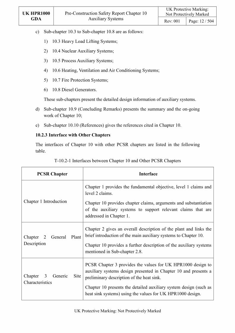
10.2.3 Interface with Other Chapters
The interfaces of Chapter 10 with other PCSR chapters are listed in the following table.
T-10.2-1 Interfaces between Chapter 10 and Other PCSR Chapters
PCSR Chapter Interface
Chapter 1 Introduction
Chapter 1 provides the fundamental objective, level 1 claims and level 2 claims.
Chapter 10 provides chapter claims, arguments and substantiation of the auxiliary systems to support relevant claims that are addressed in Chapter 1.
Chapter 2 General Plant Description
Chapter 2 gives an overall description of the plant and links the brief introduction of the main auxiliary systems to Chapter 10.
Chapter 10 provides a further description of the auxiliary systems mentioned in Sub-chapter 2.8.
Chapter 3 Generic Site Characteristics
PCSR Chapter 3 provides the values for UK HPR1000 design to auxiliary systems design presented in Chapter 10 and presents a preliminary description of the heat sink.
Chapter 10 presents the detailed auxiliary system design (such as heat sink systems) using the values for UK HPR1000 design.
UK HPR1000
GDA
Pre-Construction Safety Report Chapter 10 Auxiliary Systems
UK Protective Marking: Not Protectively Marked
Rev: 001 Page: 13 / 504
UK Protective Marking: Not Protectively Marked
PCSR Chapter Interface
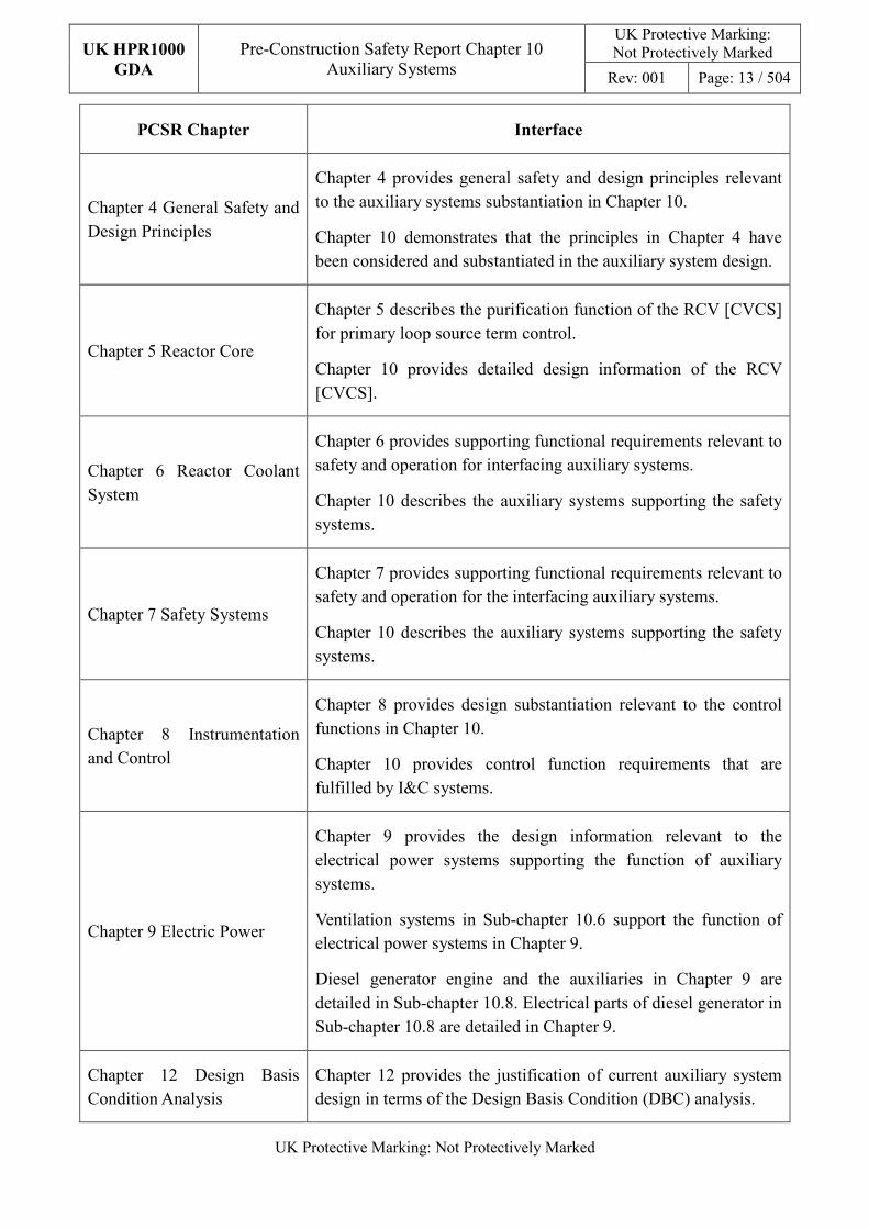
Chapter 4 General Safety and Design Principles
Chapter 4 provides general safety and design principles relevant to the auxiliary systems substantiation in Chapter 10.
Chapter 10 demonstrates that the principles in Chapter 4 have been considered and substantiated in the auxiliary system design.
Chapter 5 Reactor Core
Chapter 5 describes the purification function of the RCV [CVCS] for primary loop source term control.
Chapter 10 provides detailed design information of the RCV [CVCS].
Chapter 6 Reactor Coolant System
Chapter 6 provides supporting functional requirements relevant to safety and operation for interfacing auxiliary systems.
Chapter 10 describes the auxiliary systems supporting the safety systems.
Chapter 7 Safety Systems
Chapter 7 provides supporting functional requirements relevant to safety and operation for the interfacing auxiliary systems.
Chapter 10 describes the auxiliary systems supporting the safety systems.
Chapter 8 Instrumentation and Control
Chapter 8 provides design substantiation relevant to the control functions in Chapter 10.
Chapter 10 provides control function requirements that are fulfilled by I&C systems.
Chapter 9 Electric Power
Chapter 9 provides the design information relevant to the electrical power systems supporting the function of auxiliary systems.
Ventilation systems in Sub-chapter 10.6 support the function of electrical power systems in Chapter 9.
Diesel generator engine and the auxiliaries in Chapter 9 are detailed in Sub-chapter 10.8. Electrical parts of diesel generator in Sub-chapter 10.8 are detailed in Chapter 9.
Chapter 12 Design Basis Condition Analysis
Chapter 12 provides the justification of current auxiliary system design in terms of the Design Basis Condition (DBC) analysis.
UK HPR1000
GDA
Pre-Construction Safety Report Chapter 10 Auxiliary Systems
UK Protective Marking: Not Protectively Marked
Rev: 001 Page: 14 / 504
UK Protective Marking: Not Protectively Marked
PCSR Chapter Interface
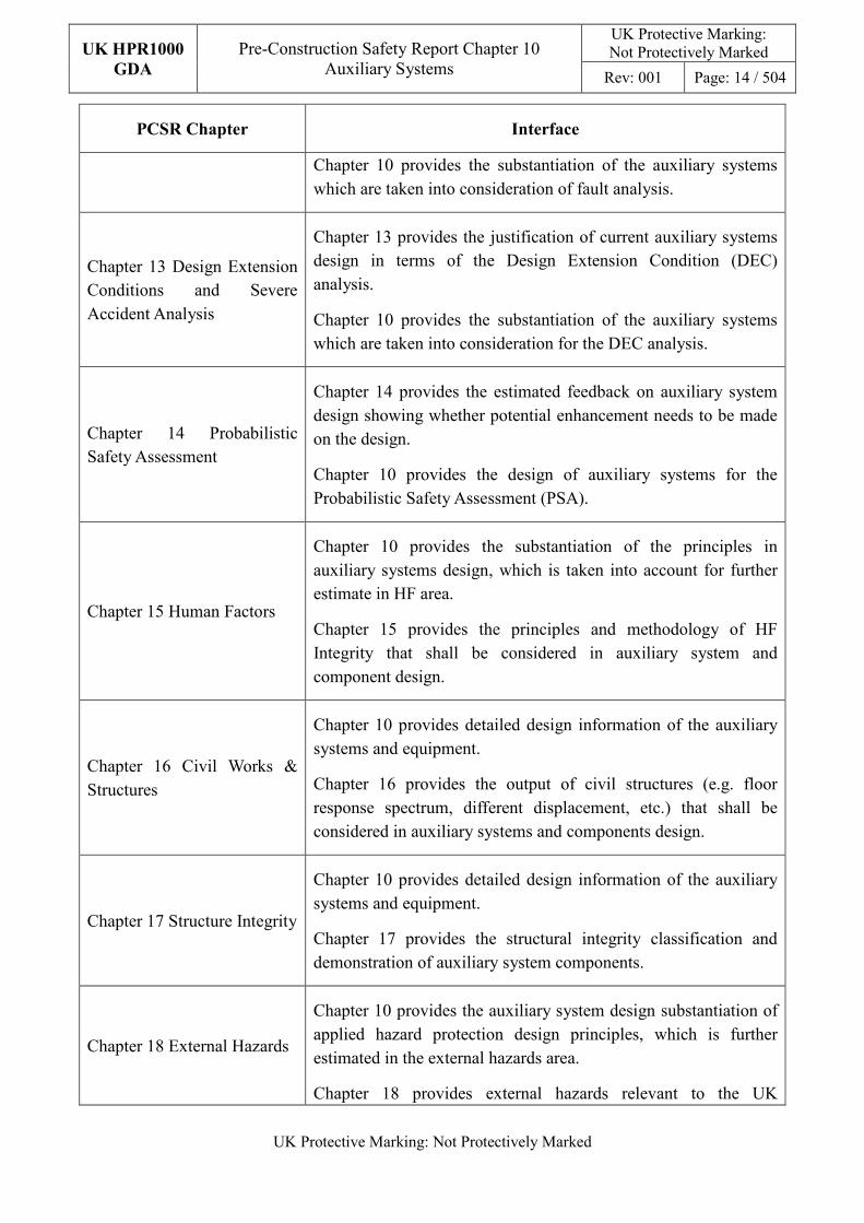
Chapter 10 provides the substantiation of the auxiliary systems which are taken into consideration of fault analysis.
Chapter 13 Design Extension Conditions and Severe Accident Analysis
Chapter 13 provides the justification of current auxiliary systems design in terms of the Design Extension Condition (DEC) analysis.
Chapter 10 provides the substantiation of the auxiliary systems which are taken into consideration for the DEC analysis.
Chapter 14 Probabilistic Safety Assessment
Chapter 14 provides the estimated feedback on auxiliary system design showing whether potential enhancement needs to be made on the design.
Chapter 10 provides the design of auxiliary systems for the Probabilistic Safety Assessment (PSA).
Chapter 15 Human Factors
Chapter 10 provides the substantiation of the principles in auxiliary systems design, which is taken into account for further estimate in HF area.
Chapter 15 provides the principles and methodology of HF Integrity that shall be considered in auxiliary system and component design.
Chapter 16 Civil Works & Structures
Chapter 10 provides detailed design information of the auxiliary systems and equipment.
Chapter 16 provides the output of civil structures (e.g. floor response spectrum, different displacement, etc.) that shall be considered in auxiliary systems and components design.
Chapter 17 Structure Integrity
Chapter 10 provides detailed design information of the auxiliary systems and equipment.
Chapter 17 provides the structural integrity classification and demonstration of auxiliary system components.
Chapter 18 External Hazards
Chapter 10 provides the auxiliary system design substantiation of applied hazard protection design principles, which is further estimated in the external hazards area.
Chapter 18 provides external hazards relevant to the UK
UK HPR1000
GDA
Pre-Construction Safety Report Chapter 10 Auxiliary Systems
UK Protective Marking: Not Protectively Marked
Rev: 001 Page: 15 / 504
UK Protective Marking: Not Protectively Marked
PCSR Chapter Interface
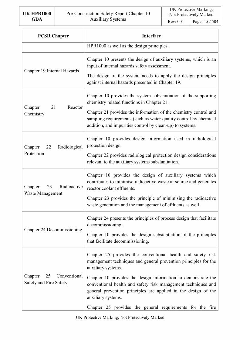
HPR1000 as well as the design principles.
Chapter 19 Internal Hazards
Chapter 10 presents the design of auxiliary systems, which is an input of internal hazards safety assessment.
The design of the system needs to apply the design principles against internal hazards presented in Chapter 19.
Chapter 21 Reactor Chemistry
Chapter 10 provides the system substantiation of the supporting chemistry related functions in Chapter 21.
Chapter 21 provides the information of the chemistry control and sampling requirements (such as water quality control by chemical addition, and impurities control by clean-up) to systems.
Chapter 22 Radiological Protection
Chapter 10 provides design information used in radiological protection design.
Chapter 22 provides radiological protection design considerations relevant to the auxiliary systems substantiation.
Chapter 23 Radioactive Waste Management
Chapter 10 provides the design of auxiliary systems which contributes to minimise radioactive waste at source and generates reactor coolant effluents.
Chapter 23 provides the principle of minimising the radioactive waste generation and the management of effluents as well.
Chapter 24 Decommissioning
Chapter 24 presents the principles of process design that facilitate decommissioning.
Chapter 10 provides the design substantiation of the principles that facilitate decommissioning.
Chapter 25 Conventional Safety and Fire Safety
Chapter 25 provides the conventional health and safety risk management techniques and general prevention principles for the auxiliary systems.
Chapter 10 provides the design information to demonstrate the conventional health and safety risk management techniques and general prevention principles are applied in the design of the auxiliary systems.
Chapter 25 provides the general requirements for the fire
UK HPR1000
GDA
Pre-Construction Safety Report Chapter 10 Auxiliary Systems
UK Protective Marking: Not Protectively Marked
Rev: 001 Page: 16 / 504
UK Protective Marking: Not Protectively Marked
PCSR Chapter Interface
protection systems design.
Sub-chapter 10.7 provides information of fire protection system related to fire safety strategy in Chapter 25.
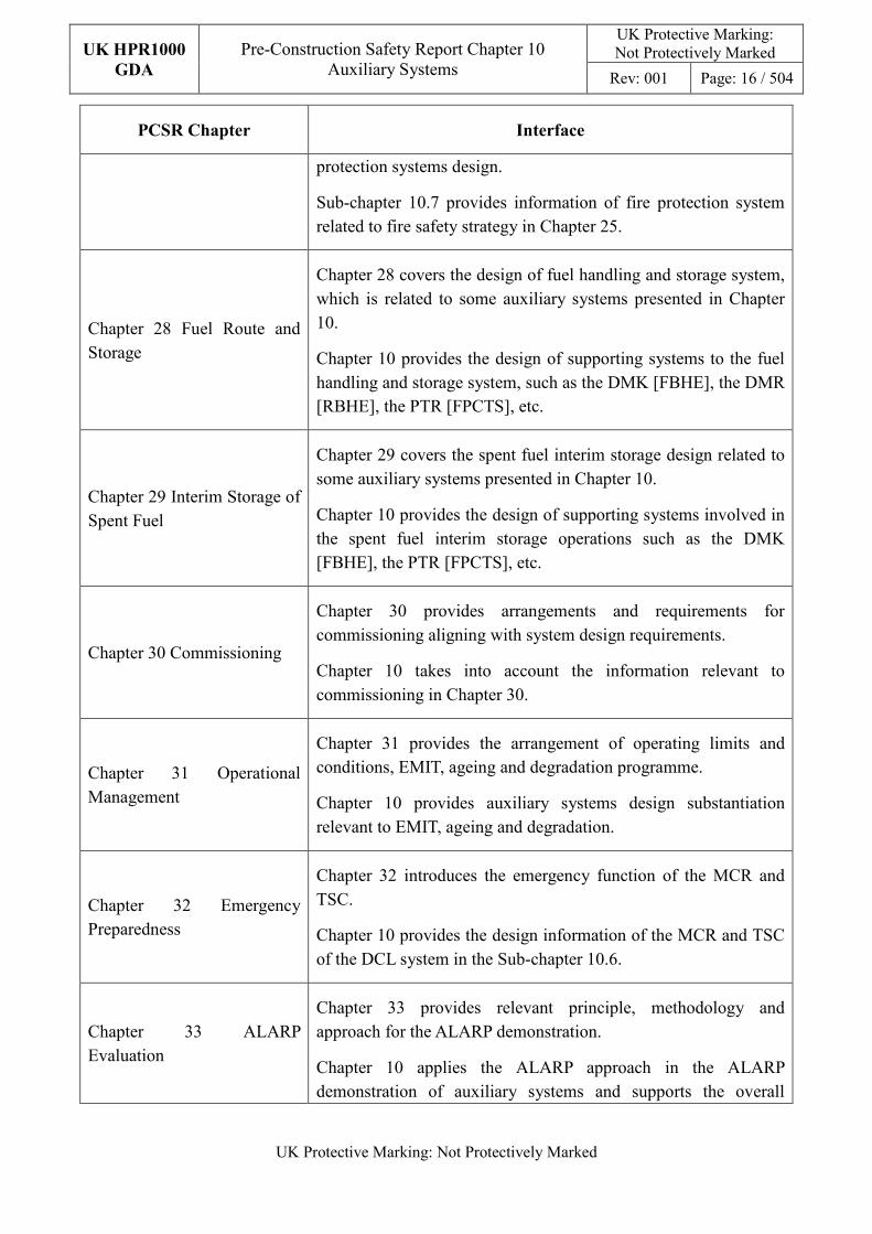
Chapter 28 Fuel Route and Storage
Chapter 28 covers the design of fuel handling and storage system, which is related to some auxiliary systems presented in Chapter 10.
Chapter 10 provides the design of supporting systems to the fuel handling and storage system, such as the DMK [FBHE], the DMR [RBHE], the PTR [FPCTS], etc.
Chapter 29 Interim Storage of Spent Fuel
Chapter 29 covers the spent fuel interim storage design related to some auxiliary systems presented in Chapter 10.
Chapter 10 provides the design of supporting systems involved in the spent fuel interim storage operations such as the DMK [FBHE], the PTR [FPCTS], etc.
Chapter 30 Commissioning
Chapter 30 provides arrangements and requirements for commissioning aligning with system design requirements.
Chapter 10 takes into account the information relevant to commissioning in Chapter 30.
Chapter 31 Operational Management
Chapter 31 provides the arrangement of operating limits and conditions, EMIT, ageing and degradation programme.
Chapter 10 provides auxiliary systems design substantiation relevant to EMIT, ageing and degradation.
Chapter 32 Emergency Preparedness
Chapter 32 introduces the emergency function of the MCR and TSC.
Chapter 10 provides the design information of the MCR and TSC of the DCL system in the Sub-chapter 10.6.
Chapter 33 ALARP Evaluation
Chapter 33 provides relevant principle, methodology and approach for the ALARP demonstration.
Chapter 10 applies the ALARP approach in the ALARP demonstration of auxiliary systems and supports the overall
UK HPR1000
GDA
Pre-Construction Safety Report Chapter 10 Auxiliary Systems
UK Protective Marking: Not Protectively Marked
Rev: 001 Page: 17 / 504
UK Protective Marking: Not Protectively Marked
PCSR Chapter Interface
ALARP demonstration addressed in Chapter 33.
10.2.4 General Design Requirements
The design requirements derived from Chapters 4, 15, 18, 19, 30, 31 and other relevant documents of general requirements are listed below. The requirements of system design which shall be considered in the system design process are also listed. Detailed description of requirements and principles is presented in supplementary submissions, References [2], [3], [4].
a) Safety Classification
The aim of the classification is to help ensure that the item is designed, manufactured, constructed, commissioned and operated according to appropriate requirements so as to achieve good quality under all expected operating conditions and realise the safety functions. The safety classification principles (including seismic categorisation principles) in the document “Methodology of
Safety Categorisation and Classification”, Reference [3], shall be considered in the design of auxiliary systems.
b) Engineering Design Requirements
1) The Reliability Design of Structures, Systems and Components (SSCs)
- Single Failure Criterion (SFC)
The SFC is considered to ensure that more than the minimum of components are provided to carry out safety functions. The criterion is applicable to a mechanical system that performs a safety function, such that it must be capable of performing its intended safety function in the presence of any single failure. It is beneficial to ensuring the high reliability of safety systems and to maintain the plant within its deterministic design basis. The redundancy design helps satisfy this criterion.
Single failures include active and passive failures:
� An active single failure is defined as a failure which could occur in a component that changes its state while fulfilling its function. For example, the malfunction of a mechanical component which relies on mechanical movement to complete its intended function, or the malfunction of an Instrumentation and Control (I&C) component;
� A passive single failure is defined as a failure which could occur in a component that does not change its state while realising its function.
UK HPR1000
GDA
Pre-Construction Safety Report Chapter 10 Auxiliary Systems
UK Protective Marking: Not Protectively Marked
Rev: 001 Page: 18 / 504
UK Protective Marking: Not Protectively Marked
The passive single failure at the start of a transient should be assessed in an appropriate means.
The single failure criterion is applied to each safety group considered in fault analysis. A single failure of active component within systems that deliver FC1 or FC2 safety functions is required to be tolerated at or after the PIE, when their action is demanded. A single failure of passive components within systems that deliver FC1 or FC2 safety functions need to be assessed at the start of a transient in an appropriate means.
Details about general principles for the SFC are provided in Reference [2].
- Independence
In addition to the high level principle of independence between levels of Defence in Depth (DiD), the following principles for independence should be applied in the design to achieve system reliability and tolerance to faults:
� Independence among redundant system components is maintained as far as reasonably practicable (avoidance of common cause failure (CCF));
� Independence between components of different safety categories is maintained as far as reasonably practicable (avoidance of impact on the component of higher safety category from an item of lower safety category);
� Independence between components designed to mitigate a potential initiating event and the effects of this potential initiating event is maintained as far as reasonably practicable;
� Independence between SSCs important to safety and those not important to safety is maintained as far as reasonably practicable.
Independence is accomplished in the design of systems by using functional isolation and/or physical separation. Functional isolation is used to reduce adverse effects between elements of connected systems or systems redundantly designed. These adverse effects may be caused by the normal operation, abnormal operation or failure of any part of these systems.
Physical separation should be applied in the layout of systems as far as reasonably practicable, to reduce the potential of CCF due to a localised initiating event. The choice of isolation measures (compartmentalisation, distance, orientation etc.) should take into account the nature of the
UK HPR1000
GDA
Pre-Construction Safety Report Chapter 10 Auxiliary Systems
UK Protective Marking: Not Protectively Marked
Rev: 001 Page: 19 / 504
UK Protective Marking: Not Protectively Marked
initiating events.
Details about general principles for independence are provided in Reference [2].
- Diversity
Diversity shall be realised appropriately by incorporating different attributes into redundant systems or components. Such attributes can be different operating principles, different physical variables, different operating conditions, different manufacturers, etc.
Details about general principles for diversity are provided in Reference [2].
- Fail-safe
According to Reference [2], the fail-safe design shall be considered and incorporated, as appropriate, into the design of systems and components important to safety of UK HPR1000, so that their failure or the failure of a support feature will not invalidate the performance of the intended safety function.
- Ageing and Degradation
Considerations:
The design life of items important to safety at a nuclear power plant shall be determined. Appropriate margins shall be provided in the design to take due account of relevant mechanisms of ageing, neutron embrittlement and wear out and of the potential for age related degradation, to ensure the capability of items important to safety to perform their necessary safety functions throughout their design life, including testing, maintenance, maintenance outages, plant states during a postulated initiating event and plant states following a postulated initiating event.
Provision shall be made for monitoring, testing, sampling and inspection to assess ageing mechanisms predicted at the design stage and to help to identify unanticipated behaviour of the plant or degradation that might occur in service.
Details about the general principles and requirements for management of ageing and degradation are addressed by asset management, including equipment qualification, state monitoring, pre-service inspection, commissioning tests, operating and Examination, Maintenance, Inspection and Testing (EMIT) and decommissioning, etc.
UK HPR1000
GDA
Pre-Construction Safety Report Chapter 10 Auxiliary Systems
UK Protective Marking: Not Protectively Marked
Rev: 001 Page: 20 / 504
UK Protective Marking: Not Protectively Marked
Common Design Measures to Fulfil the Considerations:
Ageing effects concerning individual components are taken into consideration in the system design:
� Sufficient margin has been taken in the component design to prevent failures caused by ageing effects;
� Practical examining measures are planned during plant operation (EMIT) to address the ageing effects to the components;
� For replaceable parts of components, replacement plans and layout designs are properly considered.
2) Autonomy
- Autonomy with respect to operators;
If the plant selected parameters exceed set points, the protection system shall come into action, providing automatic scram and initiation of post-trip cooling. The plant shall be designed in such a way that it meets the following autonomy objectives:
� The numerical targets of DBC-2, DBC-3, DBC-4 and DEC-A can be met without operator action from the Main Control Room (MCR) in less than 30 minutes from the first significant signal;
� The numerical targets of DBC-2, DBC-3, DBC-4 and DEC-A can be met without action outside the MCR in less than 1 hour from the first significant signal;
� No site based mobile light equipment shall be required in less than 6 hours from accident initiation, for core damage prevention actions in DEC;
� No site based mobile light equipment shall be required in less than 12 hours from accident initiation, for containment performance assurance in DEC;
� No offsite or onsite mobile heavy equipment is required in less than 72 hours in both DBCs and DECs;
� In addition, the containment system shall be designed in such a way that it can withstand any of the severe accidents considered in DEC, without operator action during the first 12 hours from the beginning of the severe accident conditions.
- Autonomy with respect to the heat sink;
Design provisions shall ensure adequate decay heat removal under DBC
UK HPR1000
GDA
Pre-Construction Safety Report Chapter 10 Auxiliary Systems
UK Protective Marking: Not Protectively Marked
Rev: 001 Page: 21 / 504
UK Protective Marking: Not Protectively Marked
and DEC, for 72 hours without external support. The initial means ensuring decay heat removal shall last at least 24 hours.
The design shall include provisions allowing additional means to ensure decay heat removal after 72 hours.
- Autonomy with respect to power supply systems.
� Electrical Power Supply
√ The period of independence of the installation in relation to external electrical power supplies shall be at least 72 hours; this applies to DBC and DEC;
√ The plant shall have an available power supply unit which is independent of the electrical power supply units designed for operational conditions and postulated accidents. It shall have sufficient capacity to support at the same time all these functions: remove decay heat, ensure primary circuit integrity, maintain reactor sub-criticality and monitor the unit state;
√ The batteries which perform FC1 and FC2 functions shall be sized so that their expected autonomy is at least 2 hours following any DBC, without recharging;
√ The batteries which perform significant safety functions shall be sized so that their expected autonomy could be 24 hours in severe accident without recharging.
� Compressed Air
Where required to support essential systems, the availability of compressed air reserves should be sufficient to be consistent with the timescale for the availability of the equipment.
3) Other Design Requirements
- Prevention of Harmful Interactions of Systems Important to Safety
The potential for harmful interactions of systems important to safety at the nuclear power plant that might be required to operate simultaneously shall be evaluated, and effects of any harmful interactions shall be prevented.
In the analysis of the potential for harmful interactions of systems important to safety, due account shall be taken of physical interconnections and of the possible effects of one system’s operation, maloperation or malfunction on local environmental conditions of other essential systems, to ensure that changes in environmental conditions do
UK HPR1000
GDA
Pre-Construction Safety Report Chapter 10 Auxiliary Systems
UK Protective Marking: Not Protectively Marked
Rev: 001 Page: 22 / 504
UK Protective Marking: Not Protectively Marked
not affect the reliability of systems or components in functioning as intended.
If two fluid systems important to safety are interconnected and are operating at different pressures, either the systems shall both be designed to withstand the higher pressure, or provision shall be made to prevent the design pressure of the system operating at the lower pressure from being exceeded.
- Considerations Related to the Electrical Power Grid
The functionality of items important to safety at the nuclear power plant shall not be compromised by disturbances in the electrical power grid, including anticipated variations in the voltage and frequency of the grid supply.
c) Equipment Qualification
Equipment qualification includes environmental and seismic qualification. Considering the results of fault analysis and the safety classifications, the specific equipment to be qualified is listed as follows:
1) Equipment required for environmental qualification:
All normal operational, fault and accident conditions should be considered in the equipment qualification process. Normal operational conditions should consider the lifetime of the equipment and the environment of the normal condition in the plant where the equipment is placed. The variation of environmental condition arising from the fault and accident conditions should be considered in the environmental qualification.
- Mechanical equipment and electrical equipment that perform FC1 or FC2 functions;
- Mechanical equipment and electrical equipment that perform FC3 functions are required:
� to maintain a safe state;
� to protect against DEC-A and mitigate DEC-B.
2) Equipment required for seismic qualification:
The equipment that performs the following functions should be seismically qualified: operability (O), functionality (F), integrity (I) or stability (S).
The parameters, which are related to the environmental conditions, and their impact on equipment are presented below:
1) Temperature
UK HPR1000
GDA
Pre-Construction Safety Report Chapter 10 Auxiliary Systems
UK Protective Marking: Not Protectively Marked
Rev: 001 Page: 23 / 504
UK Protective Marking: Not Protectively Marked
Temperature can indirectly change the performance of the equipment by gradual chemical and physical processes, which is also called thermal aging.
2) Pressure
Pressure and its rapid changes can affect the performance of equipment by exerting additional forces on the equipment. High increase of external or internal pressure may cause structural failure of the fully sealed equipment. The rapid increase of pressure may cause structural failure of the imperfectly sealed equipment.
3) Radiation
Nuclear radiation could induce changes in the atomic and molecular structure of matter through excitation, oxidation, crosslinking, degradation and shearing process resulting in the change of equipment performance. Some changes improve the performance of the equipment, but most of the changes cause a decline in the performance.
There exist four main types of radiation (α, β, γ and neutron) in nuclear power plants. γ radiation possesses a very strong capacity for penetration. On the contrary, the penetration capacity of β radiation is low, 1mm steel or a 10mm water layer can shield most of the β radiation. The penetration capacity of α radiation is even lower than β radiation. Neutron radiation is considered for equipment near the reactor pit.
4) Humidity
Humidity (high humidity) can directly lead to equipment performance degradation, and can make other environmental conditions worse. For example, moisture could lead to corrosion and current effects at the interfaces of different metals. Moisture could directly reduce the performance of organic materials, degrading their physical, mechanical and electrical performance and deforming them. Moisture on the surface can significantly reduce the insulation resistance and breakdown voltage of the insulation surface.
The methods of equipment qualification are presented below:
1) Type test under representative conditions, in accordance with an appropriate test standard;
2) Qualification by analysis:
- Calculation (design analysis), usually structural load analysis and mechanical analysis in accordance with an appropriate design code;
- Operating experience based;
UK HPR1000
GDA
Pre-Construction Safety Report Chapter 10 Auxiliary Systems
UK Protective Marking: Not Protectively Marked
Rev: 001 Page: 24 / 504
UK Protective Marking: Not Protectively Marked
- Analogy - by comparison with similar qualified equipment.
These requirements shall be considered in auxiliary systems design. Detailed information related to the equipment qualification method and relevant requirements is presented in References [5].
d) Protection against Internal and External Hazards
According to Chapter 4 and further information which is presented in Reference [4], fulfilment of the fundamental safety functions for a nuclear power plant shall be ensured in hazard protection design, as well as limitation of accidental radioactive releases.
The principles of hazard protection design are as follows:
1) The concept of DiD should be applied in the design of hazard protection;
2) Hazards should not result in the failure of any fundamental safety function of nuclear power plants;
3) Priority should be given to passive barriers, and the integrity of the barrier against individual and combined hazards should be substantiated. The acceptability of any partial loss of integrity should be evaluated;
4) The habitability of the MCR should be ensured. The availability and the accessibility of the remote shutdown station should be ensured in case the MCR is unavailable;
5) The protection design measures should ensure that there is no cliff-edge effect;
6) The hazards safety evaluation should demonstrate that the risk is reduced to be ALARP.
These principles shall be considered in systems design. For detailed information about protection requirements and measures refer to Reference [4].
The types of hazards are identified in Reference [4] for both internal hazards and external hazards. The following types of hazards shall be considered in systems design:
1) Types of internal hazards:
- Internal Fire;
- Internal Flooding;
- Internal Explosion;
- Internal Missile;
UK HPR1000
GDA
Pre-Construction Safety Report Chapter 10 Auxiliary Systems
UK Protective Marking: Not Protectively Marked
Rev: 001 Page: 25 / 504
UK Protective Marking: Not Protectively Marked
- Dropped Load;
- High Energy Pipe Failures.
2) Types of external hazards:
- Earthquakes;
- External Flooding;
- Man-made and Industrial Hazards (including aircraft crash, etc.);
- Extreme Meteorological Conditions
The hazard assessment in Chapter 18 and 19 demonstrates that the auxiliary systems are effectively protected against the identified hazards if those hazards challenge the safety objectives.
e) Commissioning
The safety related functions shall be effectively demonstrated via commissioning and testing before service. The system commissioning programme shall be established to guide the commission test onsite. The commission content, phased approach and scope are shown in Chapter 30.
f) Examination, Inspection, Maintenance and Testing
The design should be such that activities for EMIT are facilitated for the purpose of maintaining the capability of SSCs important to safety to perform essential safety functions, so as to satisfy the reliability requirement.
The types of inspections, maintenances, periodic tests, relevant requirements and the methodology of completeness analysis are presented in Chapter 31. The above activities are specified taking into account the design code requirements, reliability analysis and potential degradation mechanisms, commensurate with the safety class of the system. These requirements/principles shall be considered in the system design.
g) Decommissioning
Decommissioning shall be considered during the design stage for the UK HPR1000. At the current stage, the general considerations of decommissioning are mentioned in Chapter 24 and mainly include:
1) The consideration of facilitating decommissioning;
2) The consideration of decommissioning strategy; and,
3) The consideration of the preliminary decommissioning plan for the UK HPR1000.
UK HPR1000
GDA
Pre-Construction Safety Report Chapter 10 Auxiliary Systems
UK Protective Marking: Not Protectively Marked
Rev: 001 Page: 26 / 504
UK Protective Marking: Not Protectively Marked
The design facilitating decommissioning will be considered during the design of the auxiliary systems, the related considerations can be referred in PCSR Chapter 24.
h) Material Selection
Material selection for systems and equipment is one of the most significant factors affecting the safety of the nuclear power plant, and therefore special attention shall be paid to material selection at the design stage so that SSCs can fulfil their functions with high reliability throughout the design life of the plant.
The principles and the approach of material selection are presented in Reference [6]. According to the reference, the general principles relevant to the material selection are summarised as shown below:
1) Material selection shall be consistent with the functional objectives of the system and equipment;
2) Material selection shall be performed in a manner in which the classification shall be reflected; the requirements shall be commensurate with the classification;
3) Materials selected for use shall be compatible with the full range of environmental conditions which may be encountered over the plant design life;
4) Materials selected for use shall present high functional reliability and good resistance to aging and degradation throughout the design life to mitigate against the risk of performance degradation and failure of SSCs;
5) Materials selected for use shall possess excellent manufacturability, and shall be convenient for performing processing sequences such as forging or casting, machining, heat treatment, welding and inspection;
6) Operating Experience (OPEX) and feedback shall be taken into account for material selection of the system;
7) Generation and transportation of source terms shall be specially considered when selecting the material to be used to minimise the radiological dose of workers and the public when performing in-service inspection, maintenance, replacement and decommissioning;
8) Compatibility with the chemistry regime shall be considered when selecting the material to ensure that the components can function well under the selected chemical conditions.
i) Special Thermal-hydraulic Phenomena
Thermal-hydraulic phenomena occur during fluid system operation, induced by

UK HPR1000
GDA
Pre-Construction Safety Report Chapter 10 Auxiliary Systems
UK Protective Marking: Not Protectively Marked
Rev: 001 Page: 27 / 504
UK Protective Marking: Not Protectively Marked
normal or transient operation. Based on the feedback from the operating plant, several kinds of hydraulic phenomena may induce potential risk for the safe operation of the facility.
The thermal-hydraulic phenomena identified which shall be considered in the system design include but are not limited to:
1) Phenomenon regarding the dead leg;
2) Phenomenon regarding the hot water and cold water mixing;
3) Phenomenon regarding thermal stratification;
4) Phenomenon regarding the water hammer effect;
5) Phenomenon regarding the boiler effect.
j) Insulation
In the equipment and piping system insulation design, the following issues must be considered:
1) During plant normal operation without any maintenance work to be carried out, the insulation design shall reduce the heat loss as much as possible to save energy;
2) During plant maintenance or refuelling, the insulation design shall protect the workers from being scalded;
3) During plant maintenance or refuelling, the insulation design shall ensure the convenience of installation or replacement, especially for the equipment or piping systems containing radioactive material;
4) The principles of material selection shall be considered in insulation design. Moreover, flammable material is prohibited to prevent potential internal hazards.
k) Human Factors
Considerations:
According to Reference [2], a systematic approach needs to be applied to identify the factors that affect human performance and minimise the potential for human error throughout the entire plant lifecycle.
The design allocates functions properly, supports personnel in the fulfilment of their responsibilities and in the performance of tasks. The design also needs to identify human actions that may affect safety and proportionately analyse all tasks important to safety, and limit the likelihood of operational errors and their impact on safety.
UK HPR1000
GDA
Pre-Construction Safety Report Chapter 10 Auxiliary Systems
UK Protective Marking: Not Protectively Marked
Rev: 001 Page: 28 / 504
UK Protective Marking: Not Protectively Marked
A systematic approach on human factor integration is established and applied throughout the entire lifecycle of the UK HPR1000, especially at the design stage. Adequate consideration of human factors is given to ensure that risks from human interactions are managed to a level that is ALARP.
Human factor integration covers the plant locations where operations and maintenance activities take place. To comply with the requirements set above, the following elements will be met:
a) The design should allocate functions properly to minimise the dependence on human actions;
b) Human actions that could impact safety during normal operation, fault and accident conditions should be identified systematically. These human actions important for safety are known as Human Based Safety Claims (HBSC);
c) Appropriate human factor analysis, including task analysis and human reliability analysis, should be performed on the HBSC to identify improvements to systems, procedures or trainings;
d) All HBSC should be classified either based on their risk significance or on the significance of the safety system affected;
e) The design should support personnel in the fulfilment of their responsibilities and in the performance of tasks by providing suitable and sufficient user interfaces and workspace.
Moreover, the design of the system, components, layout, HMI and operator working environment shall meet the human factors requirements presented in the safety case of human factors. The result of system design will be further assessed with the Human Factors Engineering (HFE) Task Analysis. More information is presented in Chapter 15.
Common Design Measures to Fulfil the Considerations:
For the system design, key consideration is given to prevent human error. This is achieved by the following design measures:
1) Allocating the safety functions to manual activity and automatic control appropriately;
2) Providing necessary information to the operator.
CGN carried out the human action analysis during Step 3 of GDA according to the safety / duty functions performed by the SSCs. The outcome is presented in the Reference [7].
Also, CGN developed the preliminary local area HFE guidelines, Reference [8]. Then CGN carried out preliminary review work related to the local area HMI and
UK HPR1000
GDA
Pre-Construction Safety Report Chapter 10 Auxiliary Systems
UK Protective Marking: Not Protectively Marked
Rev: 001 Page: 29 / 504
UK Protective Marking: Not Protectively Marked
workplace, Reference [9]. Moreover, CGN carried out the baseline human factor assessment, Reference [10].
More detailed information is presented in the safety case of the Human Factor Area.
l) Equipment Supplier Design Assurance
In UK HPR1000 project, the design of mechanical equipment mainly includes following two types:
1) CGN does the basic and detailed design, and the equipment supplier manufactures the equipment according to the drawings and documents provided by CGN, e.g. residual heat removal heat exchanger, accumulator etc.
2) CGN does the basic design, drafts the technical specification, qualification requirement and other related documents; the equipment supplier does the detailed design, meets the CGN requirements, e.g. pumps, valves, strainer etc.
For the detailed design of equipment completed by the supplier, CGN needs to manage the equipment design process and ensure that the equipment designed by the supplier meets the requirements of CGN. The management requirements include:
1) Suitably qualified and experienced person requirement;
2) Prototype design requirement;
3) Prototype qualification requirement;
4) Interface exchange management;
5) Design change management;
6) Supplier documents review management, etc.
Detailed description about design assurance is presented in Reference [11]. Meanwhile, the supplier also needs to consider the impact of the human factor when they carry out the equipment design and manufacture etc., the related requirements of the human factor are presented in equipment specification.
m) Conventional Safety;
Considerations:
The design of the UK HPR1000 should be developed to eliminate, reduce, isolate or control, so far as is reasonably practicable, the conventional health and safety risks to workers and the public that may arise during the construction,
UK HPR1000
GDA
Pre-Construction Safety Report Chapter 10 Auxiliary Systems
UK Protective Marking: Not Protectively Marked
Rev: 001 Page: 30 / 504
UK Protective Marking: Not Protectively Marked
commissioning, operation, maintenance, and decommissioning of the nuclear power plant.
The designers should use the tools of design risk management, such as hazard checklist, hazard Identification workshop and risk assessment steps, in the UK HPR1000 to identify and assess the conventional health and safety risks, as well as eliminate, reduce, isolate and control them by design mitigations. And the processes should be recorded by conventional health and safety design risk register. The conventional health and safety design risk registers for each system and each building in GDA scope should be developed, and they will be continually developed throughout the lifetime of the design.
The related design processes and requirements of conventional safety are presented in Construction Design Management Strategy and CDM Design Risk
Management Work Instruction and in General Design Requirements for
Conventional Health and Safety (GHX00500001DOHB02GN).
Common Design Measures to Fulfil the Considerations:
During step 3 of UK HPR1000 GDA, the potential risks to the health and safety of worker and public during Nuclear Power Plant (NPP) constructing, operating, maintaining and decommissioning are preliminarily identified. The design measures have been taken to eliminate, reduce, isolate and control the risks to reasonably practicable low level.
The conventional health and safety risks relating to the Auxiliary Systems are analysed. The information of these risks is recorded in the conventional health and safety Design Risk Registers, which is regarded as live documents and will be continually developed throughout the lifetime of the design; this is presented in the Conventional Safety case.
n) Radioactive Waste Minimisation;
Waste minimisation is fundamental to radioactive waste management; reducing radioactive waste at source is an important means of waste minimization in the UK HPR1000. Measures to control the generation of radioactive waste, in terms of both volume and radioactivity content, is considered, beginning with the design phase, and throughout the lifetime of the facility.
The control measures are generally applied in the following order of priority in line with waste hierarchy:
a) Prevent and minimise waste generation;
b) Reuse items as originally intended;
c) Recycle materials;
UK HPR1000
GDA
Pre-Construction Safety Report Chapter 10 Auxiliary Systems
UK Protective Marking: Not Protectively Marked
Rev: 001 Page: 31 / 504
UK Protective Marking: Not Protectively Marked
d) Dispose as waste.
Detailed substantiation analysis related to the auxiliary systems design is presented in the relevant ALARP demonstration report of PCSR Chapter 23.
UK HPR1000
GDA
Pre-Construction Safety Report Chapter 10 Auxiliary Systems
UK Protective Marking: Not Protectively Marked
Rev: 001 Page: 32 / 504
UK Protective Marking: Not Protectively Marked
10.3 Heavy Load Lifting Systems
10.3.1 Sub-chapter Structure
The purpose of this sub-chapter is to present the design information of the heavy load lifting systems in the UK HPR1000 which consists of:
a) Reactor Building Handling Equipment (DMR [RBHE])
b) Fuel Building Handling Equipment (DMK [FBHE])
The structure of Sub-chapter 10.3 is as follows:
a) Sub-chapter 10.3.1-presents the sub-chapter structure.
b) Sub-chapter 10.3.2-presents the applicable codes and standards.
c) Sub-chapter 10.3.3-presents the design information of the DMR [RBHE].
d) Sub-chapter 10.3.4-presents the design information of the DMK [FBHE].
e) Sub-chapter 10.3.5-presents the ALARP assessment of the heavy load lifting systems.
f) Sub-chapter 10.3.6-presents the concluding remarks of the heavy load lifting systems.
10.3.2 Applicable Codes and Standards
The identification of applicable codes and standards in Sub-chapter 10.3 is consistent with the selection principles and process described in Chapter 4 and Reference [12].
Wherever possible, the selected codes and standards applied for the engineering substantiation are:
a) Commensurate with the categorisation of safety functions and classification of the SSC;
b) Internationally good practice recognised by UK regulator in nuclear industry;
c) The latest version. Where to select an older version, gap analysis will be carried out.
Based on the selection principles and selection process, the applicable codes and standards which are selected and used in Mechanical Engineering (ME) design are identified. During GDA step 2, the suitable analysis against the applicable codes and standards identified for the SSC design in ME area is carried out in the Reference [13]. In GDA step 3, a compliance analysis is carried out and presented in the Reference [14]. The main applicable codes and standards for the heavy load lifting systems and
components design are presented in Table T-10.3-1. Currently, the work of conformity analysis and gap analysis of the codes and standards is continuing.
UK HPR1000
GDA
Pre-Construction Safety Report Chapter 10 Auxiliary Systems
UK Protective Marking: Not Protectively Marked
Rev: 001 Page: 33 / 504
UK Protective Marking: Not Protectively Marked
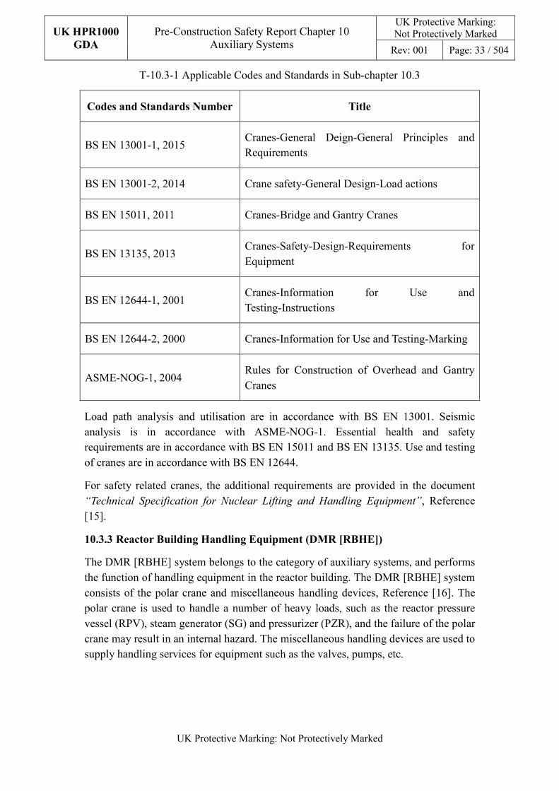
T-10.3-1 Applicable Codes and Standards in Sub-chapter 10.3
Codes and Standards Number Title
BS EN 13001-1, 2015 Cranes-General Deign-General Principles and Requirements
BS EN 13001-2, 2014 Crane safety-General Design-Load actions
BS EN 15011, 2011 Cranes-Bridge and Gantry Cranes
BS EN 13135, 2013 Cranes-Safety-Design-Requirements for Equipment
BS EN 12644-1, 2001 Cranes-Information for Use and Testing-Instructions
BS EN 12644-2, 2000 Cranes-Information for Use and Testing-Marking
ASME-NOG-1, 2004 Rules for Construction of Overhead and Gantry Cranes
Load path analysis and utilisation are in accordance with BS EN 13001. Seismic analysis is in accordance with ASME-NOG-1. Essential health and safety requirements are in accordance with BS EN 15011 and BS EN 13135. Use and testing of cranes are in accordance with BS EN 12644.
For safety related cranes, the additional requirements are provided in the document “Technical Specification for Nuclear Lifting and Handling Equipment”, Reference [15].
10.3.3 Reactor Building Handling Equipment (DMR [RBHE])
The DMR [RBHE] system belongs to the category of auxiliary systems, and performs the function of handling equipment in the reactor building. The DMR [RBHE] system consists of the polar crane and miscellaneous handling devices, Reference [16]. The polar crane is used to handle a number of heavy loads, such as the reactor pressure vessel (RPV), steam generator (SG) and pressurizer (PZR), and the failure of the polar crane may result in an internal hazard. The miscellaneous handling devices are used to supply handling services for equipment such as the valves, pumps, etc.
UK HPR1000
GDA
Pre-Construction Safety Report Chapter 10 Auxiliary Systems
UK Protective Marking: Not Protectively Marked
Rev: 001 Page: 34 / 504
UK Protective Marking: Not Protectively Marked
10.3.3.1 Safety Functional Requirements
10.3.3.1.1 Control of Reactivity
Not applicable. The DMR [RBHE] system does not perform the function of control of reactivity.
10.3.3.1.2 Removal of Heat
Not applicable. The DMR [RBHE] system does not perform the function of removal of heat.
10.3.3.1.3 Confinement
Not applicable. The DMR [RBHE] system does not perform the function of confinement.
10.3.3.1.4 Extra Safety Functions
During the refuelling stage, the polar crane handles loads in the reactor building. The RPV head assembly is the heaviest load which is required to be handled by the polar crane. Load drop, drop of significant part of crane or collision with safety related SSC may result in a hazard. In order to reduce the risk of release of radioactive substances, the design of the polar crane must minimize the risks of dropping load and damage to other safety related SSC.
10.3.3.2 Design Requirements
The general design requirements of the auxiliary systems which need to be considered are shown in Sub-chapter 10.2.4. The following requirements are not applicable for the DMR [RBHE] system.
a) Autonomy in Respect of the Heat Sink
Not applicable, because the DMR [RBHE] system does not provide a heat sink to the power plant.
b) Prevention of Harmful Interactions between Systems Important to Safety
Not applicable, because there are no harmful interactions between the DMR [RBHE] system and other systems important to safety.
c) Special Thermal-hydraulic Phenomena
Not applicable, because the DMR [RBHE] system does not have thermal-hydraulic phenomena.
d) Insulation
Not applicable, because the DMR [RBHE] system does not have insulation.
The substantiation analysis of the polar crane to other design requirements is shown in
UK HPR1000
GDA
Pre-Construction Safety Report Chapter 10 Auxiliary Systems
UK Protective Marking: Not Protectively Marked
Rev: 001 Page: 35 / 504
UK Protective Marking: Not Protectively Marked
Sub-chapter 10.3.3.5.2.
10.3.3.3 Design Bases
This sub-chapter presents the main design assumptions which are considered in the system design.
10.3.3.3.1 General Assumptions
a) Safety Classification
The DMR [RBHE] system consists of the polar crane and miscellaneous handling devices. Safety classification of the system and components complies with Sub-chapter 10.2.4.
In the GDA process, the classification of the polar crane is related to the category of the lifting schedule of the loads.
b) Ageing and Degradation
Plant lifetime and potential degradation modes are taken into consideration during the system and components design. Some components of cranes can be replaced in the plant lifetime.
c) Autonomy
The polar crane is not required to perform its function during accident conditions, but it can perform its function after maintenance.
d) Equipment Qualification
The polar crane can operate in normal conditions and it is not required to perform its function without maintenance after an accident condition. All seismically classified components maintain their integrity during and after the Safe Shutdown Earthquake (SSE).
e) Considerations Related to the Electrical Power Grid
The design of the polar crane can satisfy some variation in voltage and frequency of the electrical power grid.
f) Protection against Internal and External Hazards
The design of the polar crane is required to endure the impact of the internal and external hazards and minimize the risk of damaging the safety related SSC.
10.3.3.3.2 Design Assumptions
a) Control of Reactivity
Not applicable. The DMR [RBHE] system does not perform the function of control of reactivity.
UK HPR1000
GDA
Pre-Construction Safety Report Chapter 10 Auxiliary Systems
UK Protective Marking: Not Protectively Marked
Rev: 001 Page: 36 / 504
UK Protective Marking: Not Protectively Marked
b) Removal of Heat
Not applicable. The DMR [RBHE] system does not perform the function of removal of heat.
c) Confinement
Not applicable. The DMR [RBHE] system does not perform the function of confinement.
d) Extra Safety Functions
Load drop, drop of significant part of crane or collision with safety related SSC may both result in hazards. Thus, the polar crane is required to perform safety related functions.
The RPV head assembly is the heaviest load which is required to be handled by the polar crane in the plant refuelling stage. The capacity of the polar crane can meet the requirements of the load.
The design of the polar crane meets the following requirements:
1) The lifting schedule and lifting path of the load are designed and the lifting path is designed to avoid passing above the SSC as much as possible.
2) The polar crane is designed to minimize the risk of dropped load.
3) The polar crane is designed to minimize the risk of parts dropping from the polar crane itself.
10.3.3.4 System Description and Operation
10.3.3.4.1 System Description
a) General System Description
The DMR [RBHE] system consists of the polar crane and miscellaneous handling devices.
Detailed information is presented in the System Design Manual (SDM), Reference [17].
b) Description of Main Equipment
The lifting capacity, service area and lifting height of the crane satisfy the handling requirements of the load.
Detailed information is presented in the SDM, Reference [18].
c) Description of Main Layout
The layout of the DMR [RBHE] system meets the following requirements:

UK HPR1000
GDA
Pre-Construction Safety Report Chapter 10 Auxiliary Systems
UK Protective Marking: Not Protectively Marked
Rev: 001 Page: 37 / 504
UK Protective Marking: Not Protectively Marked
1) The layout of the crane meets the requirements for the handling of the load.
2) Systematic consideration of human factors, including the human machine interface, are considered at an early stage of the design process for a nuclear power plant and continued throughout the entire design process.
3) The design of workplaces and the working environment of the operating personnel are in accordance with ergonomic concepts.
4) From the design phase onwards, the supplier justifies the choices made in the design, in order to facilitate the maintenance of the crane during various phases.
d) Description of System Interfaces
The electric power supply system interfaces with the DMR [RBHE] system.
e) Description of Instrumentation and Control
I&C of cranes satisfy the requirements of related codes and standards.
10.3.3.4.2 System Operation
a) Plant Normal Condition
The polar crane performs its function during the refuelling stage of the plant.
b) Plant Accident Condition
The polar crane is not required to perform its function in a plant accident condition. However, it is required to perform its function after maintenance.
10.3.3.5 Preliminary Design Substantiation
In this section, the system design is demonstrated to satisfy the safety functional requirements presented in Sub-chapter 10.3.3.1 and the design requirements presented in Sub-chapter 10.3.3.2. Review of the consistency of the system design against the newly developed principles has been undertaken. Detailed design of the system is presented in the SDM, Reference [16].
10.3.3.5.1 Compliance with Safety Functional Requirements
The system configuration and the capability of the components comply with the safety functional requirements. Detailed information of the system design is presented in the SDM, Reference [16], [17] and [18].
a) Control of Reactivity
Not applicable. The DMR [RBHE] system does not perform the function of control of reactivity.
b) Removal of Heat
UK HPR1000
GDA
Pre-Construction Safety Report Chapter 10 Auxiliary Systems
UK Protective Marking: Not Protectively Marked
Rev: 001 Page: 38 / 504
UK Protective Marking: Not Protectively Marked
Not applicable. The DMR [RBHE] system does not perform the function of removal of heat.
c) Confinement
Not applicable. The DMR [RBHE] system does not perform the function of confinement.
d) Extra Safety Functions
Load drop, drop of significant part of crane or collision with safety related SSC may result in a hazard. The design of the polar crane is required to minimize the risk of dropped load and damage to other safety related SSC.
1) The lifting schedule of the RPV head assembly for the polar crane is presented in Reference [19], which demonstrates a reasonable and practicable lifting path to reduce the risk of load dropping ALARP.
2) The redundancy design of brakes and double reeving system, as well as the anti-falling mechanism, can meet the requirement of holding the load in the case of failure of critical parts and components.
3) The polar crane can maintain its structural integrity under all accident conditions, including earthquakes, airplane crashes and loss of coolant accidents.
4) The polar crane can prevent any improper movement due to the loss of the power supply. The brakes can still function properly in the case of loss of electric power.
5) The polar crane is designed to avoid any interference with the containment and the pipes on the dome of the containment.
6) The design includes double Programmable Logic Controller (PLC), one is used to control the movement of the equipment and the other is used to monitor the operation of the equipment.
10.3.3.5.2 Compliance with Design Requirement
a) Safety Classification
The DMR [RBHE] system design complies with the requirements described in the Sub-chapter 10.2.4.
For the UK HPR1000, if the design provision fails, and the severity of the consequence is “high”, the safety classification of this design provisions is defined as B-SC1. After analysing the consequence of dropped load from the polar crane, the safety classification of the polar crane is preliminarily defined as B-SC1.
UK HPR1000
GDA
Pre-Construction Safety Report Chapter 10 Auxiliary Systems
UK Protective Marking: Not Protectively Marked
Rev: 001 Page: 39 / 504
UK Protective Marking: Not Protectively Marked
b) Engineering Design Requirements
1) The Reliability Design of SSC
- Single Failure Criterion
The hoisting mechanism of each trolley is required to be designed with the criterions of single-failure-proof, which features a double reeving system and three separate braking systems.
- Independence
� The double wires are used which can support the load when one of the wires fails for each trolley of the polar crane.
� The service brake, emergency brake and safety brake can perform each of their functions independently.
- Diversity
In order to reduce the risk of the dropped load from the polar crane, the design of the polar crane meets the following requirements.
� The polar crane can be operated in the driver cab and also by a moveable control box.
� To prevent the polar crane from hoisting and traversing out of the service area, the electrical limiters and mechanical stoppers are used.
� The hoisting unit can be controlled manually. If the malfunction of the hoisting system is detected, the operators can lower the load by manual control.
� Each trolley is equipped with a drive chain detection system. The rotating speed of the motor and drum are monitored. The movement of the motor and drum are also monitored. If the divergence of the speed and movement between the motor and drum is out of specific scope, the protective system is actuated.
� Three braking systems on the hoist mechanism are used and the type of safety braking system is different from the service and emergency braking system.
- Fail-safe
The dropped load may result in a hazard, therefore measures such as redundancy and fail-safe brakes are used to improve the safety of the crane.
UK HPR1000
GDA
Pre-Construction Safety Report Chapter 10 Auxiliary Systems
UK Protective Marking: Not Protectively Marked
Rev: 001 Page: 40 / 504
UK Protective Marking: Not Protectively Marked
The fault analysis of the crane is presented in Reference [20], which identifies principle faults that can occur during lifting operations and provides safety measures required to mitigate these faults.
- Ageing and Degradation
The design considers the ageing and the degradation of the crane. The structure of the polar crane is designed to satisfy the requirements of load handling in the plant construction, operation and decommission phase and the electrical components are replaceable.
2) Human Factors
- Human Action Optimisation
� The polar crane is designed to facilitate installation, dismantling and maintenance. E.g. the maintenance hoist is designed for the polar
crane,which can be used to help the workers to replace the heavy components on the polar crane.
� The polar crane is designed to protect the operators from being hurt, such as the protection devices designed for rotating parts.
� The design of workplaces and the working environment of the operating personnel are in accordance with ergonomic concepts. E.g. the design of the cab is suitable for the size of Europeans.
� The distribution of the consoles is fitted with the operational habit of the operator in mind.
- Human Error Prevention
The design supports operating personnel in the fulfilment of their responsibilities and the performance of their tasks, and limits the effects of operating errors on safety.
� The polar crane is not allowed to move except the operator uses the key to start.
� An interlock system is required between the two means of control to prevent the polar crane being controlled by two means simultaneously.
� On the screen of the control panel, the operator can only select one trolley to operate. It is not allowed to select two or more trolleys simultaneously.
� The camera system is designed to help the operator to observe the handling conditions.
UK HPR1000
GDA
Pre-Construction Safety Report Chapter 10 Auxiliary Systems
UK Protective Marking: Not Protectively Marked
Rev: 001 Page: 41 / 504
UK Protective Marking: Not Protectively Marked
� The emergency stop is designed and incorporated.
3) Autonomy
- Autonomy in Respect of Operators
During the operation of the crane, when a fault is detected, the protection system is actuated and stops the movement of the crane automatically, such as the overload, overspeed, or power off condition.
- Autonomy in Respect of Power Supply Systems
Since the crane is not required to perform its function during accident conditions, no autonomy (generators, batteries, etc.) is required.
4) Other Design Requirements
- Considerations Related to the Electrical Power Grid
The design of the polar crane can withstand some variation in the voltage and frequency of the electrical power grid.
c) Equipment Qualification
The requirements concerning equipment qualification are presented in Chapter 4. The design of DMR [RBHE] system complies with these requirements.
1) Equipment required for environmental qualification
The equipment is required to be qualified for normal operating conditions, but is not required to be qualified for accident conditions as it does not perform its function in accident conditions.
2) Equipment required for seismic qualification
The equipment which performs a safety related function is seismically qualified. All the seismically classified components maintain their integrity during and after the SSE. The components are designed to withstand the seismic load.
d) Protection against Internal and External Hazards
Hazard protection is required to be considered for the design of polar crane. The specification is described in the SDM, Reference [17]. The design of the polar crane can withstand internal and external hazards such as fire, earthquakes, aircraft crashes and loss of power.
e) Commissioning
The polar crane is required to be subject to commissioning tests in the commissioning stage, which consist of preliminary tests, functional tests, tests
UK HPR1000
GDA
Pre-Construction Safety Report Chapter 10 Auxiliary Systems
UK Protective Marking: Not Protectively Marked
Rev: 001 Page: 42 / 504
UK Protective Marking: Not Protectively Marked
without load, tests with load and electrical tests. Checking works are required to be carried out to ensure that the polar crane can fulfil its functions, Reference [21].
f) Examination, Inspection, Maintenance and Testing
Measures are taken to enable access for inspection and testing of the components.
1) Examination and Inspection
The DMR [RBHE] system and equipment must be examined and inspected before use.
2) Maintenance
Maintenance of the crane is carried out during the refuelling stage. The main components of the crane can be repaired or replaced.
3) Periodic Tests
The DMR [RBHE] system must undergo periodic tests to ensure its ability to fulfil its function.
g) Decommissioning
The design of the DMR [RBHE] system considers the requirements of decommissioning. It can supply handling service for the equipment in the reactor building. E.g. the polar crane can be used for handling equipment in the decommissioning phase.
h) Material selection
The material selected satisfies the requirements of the load effects. The parts exposed to the air are not allowed to be manufactured with aluminium, zinc and other materials which release hydrogen while making contact with boric acid in accident conditions.
Detailed information is presented in SDM, Reference [17].
10.3.4 Fuel Building Handling Equipment (DMK [FBHE])
The DMK [FBHE] system belongs to the category of auxiliary systems, and performs the function of handling equipment in the fuel building. The DMK [FBHE] system consists of the spent fuel cask crane and miscellaneous handling devices, Reference [22]. The spent fuel cask crane is used to handle the spent fuel cask and the failure of the crane may result in an internal hazard. The miscellaneous handling devices are used to handle the equipment such as valves, pumps, etc.
UK HPR1000
GDA
Pre-Construction Safety Report Chapter 10 Auxiliary Systems
UK Protective Marking: Not Protectively Marked
Rev: 001 Page: 43 / 504
UK Protective Marking: Not Protectively Marked
10.3.4.1 Safety Functional Requirements
10.3.4.1.1 Control of Reactivity
Not applicable. The DMK [FBHE] system does not perform the function of control of reactivity.
10.3.4.1.2 Removal of Heat
Not applicable. The DMK [FBHE] system does not perform the function of removal of heat.
10.3.4.1.3 Confinement
Not applicable. The DMK [FBHE] system does not perform the function of confinement.
10.3.4.1.4 Extra Safety Functions
During the spent fuel delivery process, the spent fuel cask crane supplies handling services for spent fuel cask in the fuel building.
Load drop, drop of significant part of crane or collision with safety related SSC may result in a hazard. The spent fuel cask is used to transfer the spent fuel and failure of the spent fuel cask may result in a hazard. In order to reduce the risk of release of radioactive substances, the design of the spent cask fuel crane must minimize the risks of dropped load and damage to other safety related SSC.
10.3.4.2 Design Requirements
The general design requirements of the auxiliary systems which need to be considered are shown in Sub-chapter 10.2.4. The following requirements are not applicable for the DMK [FBHE] system.
a) Autonomy in Respect of the Heat Sink
Not applicable, the DMK [FBHE] system does not provide a heat sink to the power plant.
b) Prevention of Harmful Interactions between Systems Important to Safety
Not applicable, there are no harmful interactions between the DMK [FBHE] system and other systems important to safety.
c) Special Thermal-hydraulic Phenomena
Not applicable, the DMK [FBHE] system does not have thermal-hydraulic phenomena.
d) Insulation
Not applicable, the DMK [FBHE] system does not have insulation.
UK HPR1000
GDA
Pre-Construction Safety Report Chapter 10 Auxiliary Systems
UK Protective Marking: Not Protectively Marked
Rev: 001 Page: 44 / 504
UK Protective Marking: Not Protectively Marked
The substantiation analysis of the spent fuel cask crane to other design requirements is shown in the Sub-chapter 10.3.4.5.2.
10.3.4.3 Design Bases
This sub-chapter presents the main design assumptions considered in the system design.
10.3.4.3.1 General Assumptions
a) Safety Classification
The DMK [FBHE] system consists of the spent fuel cask crane and miscellaneous handling devices. Safety classification of the system and components complies with Sub-chapter 10.2.4.
In the GDA process, the classification of the spent fuel cask crane is related to the category of the lifting schedule of the loads.
b) Ageing and Degradation
Plant lifetime and potential degradation modes are taken into consideration during the system and components design. Some of the crane components can be replaced in the plant lifetime.
c) Autonomy
The spent fuel cask crane is not required to perform its function during accident conditions, but it can perform its function after maintenance.
d) Equipment Qualification
The spent fuel cask crane can operate in normal conditions and it can be functional following maintenance after an accident condition. All the seismically classified components maintain their integrity during and after the SSE.
e) Considerations Related to the Electrical Power Grid
The design of the crane can satisfy some variation in voltage and frequency of the electrical power grid.
f) Protection against Internal and External Hazards
The design of the spent fuel cask crane is required to endure the impact of the internal and external hazards and avoid damaging safety related SSC.
10.3.4.3.2 Design Assumptions
a) Control of Reactivity
Not applicable. The DMK [FBHE] system does not perform the function of control of reactivity
UK HPR1000
GDA
Pre-Construction Safety Report Chapter 10 Auxiliary Systems
UK Protective Marking: Not Protectively Marked
Rev: 001 Page: 45 / 504
UK Protective Marking: Not Protectively Marked
b) Removal of Heat
Not applicable. The DMK [FBHE] system does not perform the function of removal of heat.
c) Confinement
Not applicable. The DMK [FBHE] system does not perform the function of confinement.
d) Extra Safety Functions
Load drop, drop of significant part of crane or collision with safety related SSCs may result in a hazard. Thus, the spent fuel cask crane is required to perform safety related functions.
The spent fuel cask crane is required to handle the cask in the process of spent fuel cask delivery. The lifting capacity of the spent fuel cask crane can meet the requirements of the load.
The design of the spent fuel cask crane meets the following requirements:
1) The transfer process of the spent fuel cask is presented in Sub-chapter 28.4.3.
2) The spent fuel cask crane has been designed to minimize the risk of dropping the load.
3) The spent fuel cask crane has been designed to minimize the risk of parts dropping from the crane itself.
10.3.4.4 System Description and Operation System Description
10.3.4.4.1 System Description
a) General System Description
The DMK [FBHE] system consists of the spent fuel cask crane and miscellaneous handling devices.
Detailed information is presented in the SDM, Reference [23].
b) Description of Main Equipment
The lifting capacity, service area and lifting height of the cranes satisfy the handling requirements of the load.
Detailed information is presented in the SDM, Reference [24].
c) Description of Main Layout
The layout of the DMK [FBHE] system meets the following requirements:
1) The layout of the crane meets the requirements for the handling of the spent
UK HPR1000
GDA
Pre-Construction Safety Report Chapter 10 Auxiliary Systems
UK Protective Marking: Not Protectively Marked
Rev: 001 Page: 46 / 504
UK Protective Marking: Not Protectively Marked
fuel cask.
2) Systematic consideration of human factors, including the human machine interface, are included at an early stage of the design process for a nuclear power plant and continued throughout the entire design process.
3) The design of workplaces and the working environment of the operating personnel are in accordance with ergonomic concepts.
4) From the design onwards, the supplier justifies the choices made in the design, in order to facilitate the maintenance of the crane during various phases.
d) Description of System Interfaces
The electric power supply system has interface with the DMK [FBHE] system.
e) Description of Instrumentation and Control
I&C of cranes satisfy the requirements of the related codes and standards.
10.3.4.4.2 System Operation
a) Plant Normal Condition
The spent fuel cask crane performs its function during the transfer process of the spent fuel cask.
b) Plant Accident Condition
The spent fuel cask crane is not required to perform its function in plant accident conditions. However, it is required to perform its function after maintenance.
10.3.4.5 Preliminary Design Substantiation
In this section, the system design is demonstrated to satisfy the safety functional requirements presented in Sub-chapter 10.3.4.1 and the general design requirements stated in Sub-chapter 10.3.4.2. A review of the consistency of the system design against the newly developed principles is currently being undertaken. The detailed design of the system is presented in the SDM, Reference [22].
10.3.4.5.1 Compliance with Safety Functional Requirement
The system configuration and the capability of the components comply with the safety functional requirements; detailed information of the system design is presented in the SDM, Reference [22], [23] and [24].
a) Control of Reactivity
Not applicable. The DMK [FBHE] system does not perform the function of control of reactivity.
UK HPR1000
GDA
Pre-Construction Safety Report Chapter 10 Auxiliary Systems
UK Protective Marking: Not Protectively Marked
Rev: 001 Page: 47 / 504
UK Protective Marking: Not Protectively Marked
b) Removal of Heat
Not applicable. The DMK [FBHE] system does not perform the function of removal of heat.
c) Confinement
Not applicable. The DMK [FBHE] system does not perform the function of confinement.
d) Extra Safety Functions
Load drop, drop of significant part of crane or collision with safety related SSC may result in a hazard. The design of the spent fuel cask crane is required to minimize the risk of dropped load and damage to other safety related SSC.
1) Detailed information of the transfer process of the spent fuel cask is described in the Sub-chapter 28.4.3.
2) The redundancy design of the spent fuel cask crane, such as brakes and double reeving system, as well as the anti-falling mechanism, can meet the requirement of holding the load in the case of failure of critical parts and components.
3) The spent fuel cask crane can maintain its structural integrity under all accident conditions, including earthquakes, airplane crashes and loss of coolant accidents.
4) The spent fuel cask crane can prevent any improper movement due to the loss of the power supply. The brakes can still function properly in the case of loss of electric power.
5) The design includes double PLC, one is used to control the movement of the equipment and the other is used to monitor the operation of the equipment.
10.3.4.5.2 Compliance with Design Requirements
a) Safety Classification
The DMK [FBHE] system design is compliant with the requirements described in Sub-chapter 10.2.4.
For the UK HPR1000, if the design provision fails, and the severity of the consequence is “medium”, the safety classification of this design provisions is defined as B-SC2. After analysing the consequence of dropped load from the spent fuel cask crane, the safety classification of the spent fuel cask crane is preliminarily defined as B-SC2 for the UK HPR1000.
b) Engineering Design Requirements
UK HPR1000
GDA
Pre-Construction Safety Report Chapter 10 Auxiliary Systems
UK Protective Marking: Not Protectively Marked
Rev: 001 Page: 48 / 504
UK Protective Marking: Not Protectively Marked
1) Reliability Design of SSC
- Single Failure Criterion
The hoisting mechanism of the spent fuel cask crane is designed with the criterion of single-failure-proof, which features double drum, double reeving system and three separate braking systems. The reducers are designed with a closed gear drive mechanism.
- Independence
• Double wires are used which can support the load when one of the wires fails for each trolley of the spent fuel cask crane.
• The service brake, emergency brake and safety brake can perform each of their functions independently.
- Diversity
In order to reduce the risk of the dropped load from the spent fuel cask crane, the design of the spent fuel cask crane meets the following requirements:
• To prevent the spent fuel cask crane from hoisting and traversing out of the service area, the electrical limiters and mechanical stoppers are used.
• The hoisting unit can be controlled manually. When the malfunction of the hoisting system is detected, the operators can lower the load by manual control.
• The trolley is equipped with a drive chain detection system. The rotating speed of the motor and drum are monitored. The movement of the motor and the drum are also monitored. If the divergence of the speed and movement between the motor and the drum is out of specific scope, the protective system is actuated.
• Three braking systems on the hoist mechanism are used and the type of the safety braking system is different from the service and emergency braking system.
- Fail-safe
The dropped load may result in a hazard, therefore measures such as redundancy of double reeving system and fail-safe brakes which will be immediately closed in the case of loss of electric power are used to improve the safety of the crane.
The fault analysis of the crane is presented in Reference [20], which
UK HPR1000
GDA
Pre-Construction Safety Report Chapter 10 Auxiliary Systems
UK Protective Marking: Not Protectively Marked
Rev: 001 Page: 49 / 504
UK Protective Marking: Not Protectively Marked
identifies principle faults that can occur during lifting operations and provides safety measures required to mitigate these faults.
- Ageing and Degradation
The design of the crane considers the ageing and the degradation of the crane. The structure of the spent fuel cask crane is designed to satisfy the requirements of load handling in the plant operation phase and the electrical components are replaceable.
2) Human Factors
- Human Action Optimisation
• The spent fuel cask crane is designed to facilitate installation, dismantling and maintenance.
• The equipment is designed to protect the operators from being hurt. E.g. a protection device is designed on the platform of the spent fuel pool for operators.
• The design of workplaces and the working environment of the operators are in accordance with ergonomic concepts.
• The distribution of the consoles is fitted for the operational habits of the operator.
- Human Error Prevention
The design supports operating personnel in the fulfilment of their responsibilities and the performance of their tasks, and limits the effects of operating errors on safety.
• The spent fuel cask crane is not allowed to move except the operator uses the key to start.
• The operator can only select one control box to operate.
• The emergency stop is designed and incorporated.
3) Autonomy
- Autonomy in Respect of Operators
During the operation of the crane, when a fault is detected, the protect system is actuated and stops the movement of the crane automatically, such as overload, overspeed, or power off condition.
- Autonomy in Respect of Power Supply Systems
Since the crane is not required to perform its function during accident
UK HPR1000
GDA
Pre-Construction Safety Report Chapter 10 Auxiliary Systems
UK Protective Marking: Not Protectively Marked
Rev: 001 Page: 50 / 504
UK Protective Marking: Not Protectively Marked
conditions, no autonomy (generators, batteries, etc.) is required.
4) Other Design Requirements
- Considerations Related to the Electrical Power Grid
The design of the crane can withstand some variation in the voltage and frequency of the electrical power grid.
c) Equipment Qualification
The requirements concerning equipment qualification are presented in Chapter 4. The design of DMK [FBHE] system complies with these requirements.
1) Equipment required for environmental qualification
The equipment is required to be qualified for normal operating conditions, but is not required to be qualified for accident conditions as it does not perform its function in accident conditions.
2) Equipment required for seismic qualification
The equipment which performs a safety related function is seismically qualified. All the seismically classified components maintain their integrity during and after the SSE. The components are designed to withstand the seismic load.
d) Protection against Internal and External Hazards
Hazard protection is required to be considered for the design of the spent fuel cask crane. The specification is described in the SDM, Reference [23]. The design of the spent fuel cask crane can withstand internal and external hazards such as fire, earthquakes, aircraft crashes and loss of power.
e) Commissioning
The spent fuel cask crane is required to be subject to commissioning tests in the commissioning stage, which consist of preliminary tests, functional tests, no-load tests, load tests and electrical tests. Checking works are required to be carried out to ensure that the spent fuel cask crane can fulfil its functions, Reference [25].
f) Examination, Inspection, Maintenance and Testing
Measures are taken to enable access for the inspection and testing of the components.
1) Examination and Inspection
The DMK [FBHE] system and equipment must be examined and inspected before use.
UK HPR1000
GDA
Pre-Construction Safety Report Chapter 10 Auxiliary Systems
UK Protective Marking: Not Protectively Marked
Rev: 001 Page: 51 / 504
UK Protective Marking: Not Protectively Marked
2) Maintenance
The main components of the crane can be repaired or replaced.
3) Periodic Tests
The DMK [FBHE] system must undergo periodic tests to ensure its ability to fulfil its function.
g) Decommissioning
The design of the DMK [FBHE] system considers the requirements of the decommissioning.
h) Material selection
The material selected satisfies the load requirements.
Detailed information is presented in the SDM, Reference [23].
10.3.5 ALARP Assessment
10.3.5.1 General Description
Preliminary ALARP analysis has been performed on the heavy load lifting systems. The analysis is consistent with the arguments stated in Sub-claim 3.3.6.SC10.3 in the route map presented in Appendix A:
Argument 3.3.6.SC10.3-A1: The SSC meet the requirements of the relevant design principles (generic and system specific) and therefore of Relevant Good Practice (RGP).
The ALARP assessment is carried out following the ALARP methodology presented in Chapter 33. A specific ALARP demonstration report has been prepared, Reference [14].
10.3.5.2 Review of the Design against RGP & OPEX
RGP for SSC design is identified in Sub-chapter 10.3.2. The consistency analysis between the current design and RGP is still under development to ensure that the design of the SSC meets the requirements of the UK context.
The review of the design of heavy load lifting systems against the OPEX is currently being carried out.
10.3.5.3 Insight from Risk Analysis
The risk analysis is currently being developed and a preliminary result has been produced, based on which no insight is received. The analysis will continue as the GDA progresses.
UK HPR1000
GDA
Pre-Construction Safety Report Chapter 10 Auxiliary Systems
UK Protective Marking: Not Protectively Marked
Rev: 001 Page: 52 / 504
UK Protective Marking: Not Protectively Marked
10.3.5.4 Specific Review of Potential Improvements
At this stage, some gaps are identified and the review is continuing, the analysis and optioneering will be undertaken.
10.3.5.5 ALARP Demonstration
A compliance analysis of the system design with the UK HPR1000 general safety engineering principles is made in the system section. The analysis shows that two gaps are identified. Meanwhile, technical assessments such as the hazard schedule, fault schedule, PSA, and human factors are being developed simultaneously. The analysis of the design against the requirements of these technical disciplines needs to be reviewed periodically. A systematic review will be carried out on the system design to ensure that no new gaps are identified between the newly developed requirements and the design. Any potential enhancements identified during this review will be taken into account in the further development of the design.
Argument 3.3.6.SC10.3-A2: PSA indicates the SSCs are not a disproportionate contributor to risk:
Since the PSA and the fault analysis are still under development, further ALARP analysis will be performed once the fault schedule work is finished.
If any new gap is identified during the systematic technical review, analysis and optioneering will be undertaken to determine whether there are possible enhancements to the current system design, in order to reduce the risk as low as reasonably practicable.
Argument 3.3.6.SC10.3-A3: Design improvements have been considered in the SSCs and any reasonably practicable changes implemented:
Design improvements will be carried out once the potential areas of improvement in the design are identified. The ALARP assessment will be further developed to evaluate the design improvements.
In summary, the ALARP analysis and demonstration work is currently being carried out. A preliminary ALARP demonstration topic report to present the current analysis results as well as the arrangement for future ALARP analysis work is presented in Reference [14].
10.3.6 Concluding Remarks
This sub-chapter provides an introduction of the design information of the heavy load lifting systems in the UK HPR1000 nuclear power plant.
According to the preliminary assessment, the fundamental safety targets related to the heavy load lifting systems have been achieved by proper design of the system and equipment.
UK HPR1000
GDA
Pre-Construction Safety Report Chapter 10 Auxiliary Systems
UK Protective Marking: Not Protectively Marked
Rev: 001 Page: 53 / 504
UK Protective Marking: Not Protectively Marked
As the factors mentioned above may affect the current design, a systematic review will be carried out after the preliminary work has been completed. Further demonstrations or improvements will be implemented during the GDA process until the risks have been reduced ALARP.
10.4 Nuclear Auxiliary Systems
10.4.1 Sub-chapter Structure
The structure of Sub-chapter 10.4 is as follows:
a) Sub-chapter 10.4.1 (Sub-chapter Structure) gives the overall structure of Sub-chapter 10.4;
b) Sub-chapter 10.4.2 (Applicable Codes and Standards) presents the relevant codes and standards adopted in this chapter;
c) Sub-chapters 10.4.3 to 10.4.9 present the following nuclear auxiliary systems:
1) 10.4.3 Chemical and Volume Control System (RCV [CVCS]);
2) 10.4.4 Reactor Boron and Water Makeup System (REA [RBWMS]);
3) 10.4.5 Coolant Storage and Treatment System (TEP [CSTS]);
4) 10.4.6 Nuclear Sampling System (REN [NSS]);
5) 10.4.7 Fuel Pool Cooling and Treatment System (PTR [FPCTS]);
6) 10.4.8 Component Cooling Water System (RRI [CCWS]);
7) 10.4.9 Essential Service Water System (SEC [ESWS]).
These sub-chapters present the detailed description of the nuclear auxiliary systems;
d) Sub-chapter 10.4.10 (ALARP Assessment) presents the preliminary ALARP analysis of this chapter;
e) Sub-chapter 10.4.11 (Concluding Remarks) presents the summary and the on-going work of this chapter;
10.4.2 Applicable Codes and Standards
The identification of applicable codes and standards in Sub-chapter 10.4 is compliant with the general principles of codes and standards selection stated in Chapter 4 and Reference [12].
Wherever possible, the standards applied for the engineering substantiation should be:
a) Internationally recognised in nuclear industry;
b) The latest or currently applicable approved standards; and
c) Consistent with the plant reliability goals necessary for safety.
UK HPR1000
GDA
Pre-Construction Safety Report Chapter 10 Auxiliary Systems
UK Protective Marking: Not Protectively Marked
Rev: 001 Page: 54 / 504
UK Protective Marking: Not Protectively Marked
Based on these principles, the applicable codes and standards which are selected and used in Mechanical Engineering (ME) design are identified. During GDA step 2, the suitability analysis against the applicable codes and standards identified for the SSCs design in ME area are carried out in the Reference [13]. In step 3, a compliance analysis is carried out and presented in Reference [14]. The main applicable codes and standards for the nuclear auxiliary systems and components design are presented in Table T-10.4-1.
Currently, the work of conformity analysis and gap analysis of the codes and standards is continuing.
T-10.4-1 Applicable Codes and Standards in Sub-chapter 10.4
Codes and Standards Number Title
IAEA, SSR-2/1, 2016 Safety of Nuclear Power Plants: Design
IAEA, NS-G 1.9, 2004 Design of the Reactor Coolant System and Associated Systems in Nuclear Power Plants Safety Guide
RCC-M, 2007 Design and Construction Rules for Mechanical Components of Pressurised Water Reactor (PWR) Nuclear Islands (RCC-M)
RSE-M, 2010+2012 Addenda In-service Inspection Rules for Mechanical Components of PWR Nuclear Islands
10.4.3 Chemical and Volume Control System (RCV [CVCS])
RCV [CVCS] performs the functions of reactivity control, volume control and chemical control. The RCV [CVCS] consists of a letdown line, purification unit, hydrogenation station, charging line, chemical injection unit, seal injection line and seal leak-off line. The main components of the RCV [CVCS] (heat exchangers, pressure reducing valves, charging pumps, volume control tank, demineralisers and filters) are located in the reactor building, fuel building and nuclear auxiliary building of the Nuclear Island (NI). Information of the system is presented in the SDM, Reference [26].
10.4.3.1 Safety Functional Requirements
The requirements of the fundamental safety functions of the RCV [CVCS] system design are identified as follows:
10.4.3.1.1 Control of Reactivity
The RCV [CVCS] shall contribute to the control of reactivity as follows:
UK HPR1000
GDA
Pre-Construction Safety Report Chapter 10 Auxiliary Systems
UK Protective Marking: Not Protectively Marked
Rev: 001 Page: 55 / 504
UK Protective Marking: Not Protectively Marked
a) The RCV [CVCS] shall adjust the Reactor Coolant System (RCP [RCS]) boron concentration together with the Reactor Boron and Water Makeup System (REA [RBWMS]) to compensate for operational leaks and slow variations of core reactivity in all plant operation conditions;
b) The RCV [CVCS] shall ensure the automatic isolation of the RCV [CVCS] charging pump suction when the anti-dilution protection signal is triggered so as to prevent homogeneous or heterogeneous boron dilution accidents.
10.4.3.1.2 Removal of Heat
The RCV [CVCS] shall contribute to the removal of heat as follows:
a) To ensure that the fuel shall be cooled during normal operation and in the event of a very small break in RCP [RCS], the RCV [CVCS] shall maintain the water inventory of the RCP [RCS] by regulation of letdown flow and charging flow;
b) In DBC-3/4 and DEC-A conditions, RCV [CVCS] shall ensure the automatic isolation of letdown line to maintain the water inventory of the RCP [RCS].
10.4.3.1.3 Confinement
The RCV [CVCS] shall contribute to the confinement as follows:
a) The RCV [CVCS] shall ensure the automatic isolation of the containment isolation valves in the DBC-3/4 and the DEC-A conditions;
b) The RCV [CVCS] shall ensure the automatic isolation of the Reactor Coolant Pressure Boundary (RCPB) valves in the DBC-3/4 and the DEC-A conditions;
c) In normal operating condition, before the reactor coolant pumps get started, the RCV [CVCS] shall supply cooled and purified seal water to the reactor coolant pumps to prevent leaking of the reactor coolant from leaking through the seal of the reactor coolant pumps;
d) In normal operating condition, the RCV [CVCS] shall provide auxiliary spray for the pressuriser to prevent the pressuriser from overpressure;
e) In Steam Generator Tube Rupture (SGTR) condition, the RCV [CVCS] shall ensure the automatic isolation of the charging line and auxiliary spray line to avoid leakage towards the secondary loop, overflowing of the affected Steam Generator (SG) and prevent leakage at break points.
10.4.3.1.4 Extra Safety Functions
The extra safety functional requirements of the RCV [CVCS] are identified as follows:
a) The hydrogen supply line to the gas separator should be isolated after receiving a protection signal so as to prevent the risk of hydrogen explosion hazards;
UK HPR1000
GDA
Pre-Construction Safety Report Chapter 10 Auxiliary Systems
UK Protective Marking: Not Protectively Marked
Rev: 001 Page: 56 / 504
UK Protective Marking: Not Protectively Marked
b) The integrity of components and lines that are associated with the RRI [CCWS] shall be ensured such that the cooling functions of these higher-classified users of the Component Cooling Water System (RRI [CCWS]) are not affected;
c) The RCV [CVCS] shall ensure the automatic isolation of the letdown line when the temperature downstream of the letdown heat exchanger exceeds the threshold to prevent the containment penetration from exceeding the temperature limit to support the confinement function.
d) The RCV [CVCS] shall ensure the automatic bypass of the purification unit when the temperature downstream of the letdown heat exchanger exceeds the threshold so as to protect the purification unit.
e) The RCV [CVCS] shall ensure the automatic isolation of the charging line and auxiliary spray line when the SG Pressure Low 4 and safety injection signal are both triggered to ensure the RIS [SIS] injection into the core.
10.4.3.2 Design Requirements
The general design requirements of the nuclear auxiliary systems which need to be considered are shown in Sub-chapter 10.2.4, among which the following requirements are not applicable for the RCV [CVCS] system:
a) Autonomy with respect to the Heat Sink
Not applicable, because the RCV [CVCS] system doesn’t provide heat sink function to the power plant.
The substantiation analysis of the RCV [CVCS] system to other design requirements is shown in the Sub-chapter 10.4.3.5.
10.4.3.3 Design Bases
10.4.3.3.1 General Assumptions
a) Safety Classification
The RCPB isolation function is required to confine radioactive substances in DBC-2/3/4 and DEC-A conditions, the function category is FC1.
The containment isolation function is required to confine the radioactive substances in DBC-2/3/4 and DEC-A conditions, the function category is FC1.
The anti-dilution protection function is required to prevent dilution accident in DBC-2 and DEC-A conditions, the function category is FC1.
b) Ageing and Degradation
The main components of the RCV [CVCS] such as the regenerative heat exchanger, letdown heat exchangers, volume control tank, charging pumps are
UK HPR1000
GDA
Pre-Construction Safety Report Chapter 10 Auxiliary Systems
UK Protective Marking: Not Protectively Marked
Rev: 001 Page: 57 / 504
UK Protective Marking: Not Protectively Marked
required to have a service life of 60 years.
c) Considerations Related to the Electrical Power Grid
The functionality of items important to safety at the nuclear power plant shall not be compromised by disturbances in the electrical power grid, including anticipated variations in the voltage and frequency of the grid supply. In the RCV [CVCS] design, the flowrate of the charging pumps can be influenced by the fluctuation of the power grid; this effect is prevented in the operation design of the charging pumps. The information related to the grid connection is presented in the PCSR Chapter 3.
10.4.3.3.2 Design Assumptions
This sub-chapter presents the main design assumptions considered in the system design.
a) Control of Reactivity
The RCV [CVCS] is required to contribute to the anti-inadvertent-dilution protection function by isolating the charging pumps’ suction from potential dilution sources. The closing time of the anti-dilution isolation valves shall be less than 30s.
b) Removal of Heat
There’s no quantitative safety-related design assumption for the RCV [CVCS].
c) Confinement
There’s no quantitative safety-related design assumption for RCV [CVCS].
d) Extra Safety Functions
There’s no quantitative safety-related design assumption for RCV [CVCS].
10.4.3.4 System Description and Operation
10.4.3.4.1 System Description
a) General System Description
The RCV [CVCS] is designed to maintain and purify the reactor coolant by continuous letdown flow and charging flow. The RCV [CVCS] consists of one letdown line and one charging line. The redundant components of RCV [CVCS] are powered from different electrical zones to meet the SFC. And the components of RCV [CVCS] which are FC1-classified are physically separated.
The composition of RCV [CVCS] is described below:
1) Letdown Line
UK HPR1000
GDA
Pre-Construction Safety Report Chapter 10 Auxiliary Systems
UK Protective Marking: Not Protectively Marked
Rev: 001 Page: 58 / 504
UK Protective Marking: Not Protectively Marked
There is a regenerative heat exchanger, two parallel letdown heat exchangers and two parallel high-pressure reducing valves on the high-pressure letdown line. The regenerative heat exchanger and the letdown heat exchanger together reduce the temperature of reactor coolant to a target value, and the high-pressure reducing valve depressurizes the pressure. And there is a low-pressure reducing valve on the low-pressure letdown line, which is used to depressurize the pressure of the reactor coolant from RIS [SIS] in Residual Heat Removal (RHR) mode.
2) Purification Unit
Two parallel reactor coolant filters, two parallel mixed-bed demineralisers, one cation-bed demineraliser and two parallel resin trapping filters form the purification unit. These devices provide the purification function for the reactor coolant. Downstream of the purification unit, there is also a degassing unit of the Coolant Storage and Treatment System (TEP [CSTS]) which can remove the dissolved gas as needed.
3) Hydrogenation Station
The hydrogenation unit consists of a water jet pump, a mixing pipe and a gas separator. The hydrogenation station continuously adds hydrogen into the reactor coolant in order to keep the dissolved hydrogen concentration of the reactor coolant at the required value.
4) Volume Control Tank (VCT)
The VCT is located downstream the purification unit and provide water source for the charging pump as long as the level of VCT is high enough.
5) Chemical Injection Unit
The chemical injection unit consists of a chemical injection pump and a chemical injection tank. According to the need, 7LiOH, hydrazine or hydrogen peroxide will be injected into the reactor coolant for water chemistry control through the chemical injection unit.
6) Charging Line
There are two parallel charging pumps on the charging line. The reactor coolant will be sent back to the Reactor Coolant System (RCP [RCS]) via the charging pump. In addition, there is also an auxiliary spray line which can provide auxiliary spray as needed.
7) Seal Injection Line and Seal Leak-off Line
There are two parallel seal injection filters on the seal injection line and one seal leak-off filter on the seal leak-off line. RCV [CVCS] provides the seal
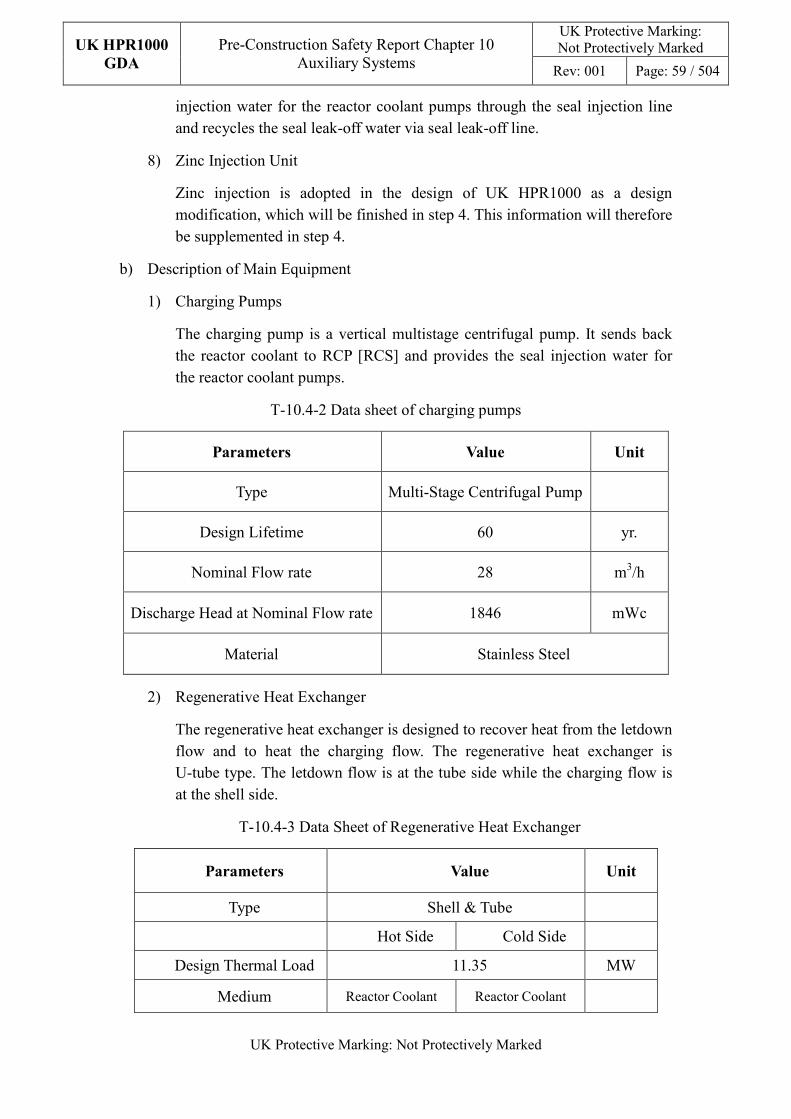
UK HPR1000
GDA
Pre-Construction Safety Report Chapter 10 Auxiliary Systems
UK Protective Marking: Not Protectively Marked
Rev: 001 Page: 59 / 504
UK Protective Marking: Not Protectively Marked
injection water for the reactor coolant pumps through the seal injection line and recycles the seal leak-off water via seal leak-off line.
8) Zinc Injection Unit
Zinc injection is adopted in the design of UK HPR1000 as a design modification, which will be finished in step 4. This information will therefore be supplemented in step 4.
b) Description of Main Equipment
1) Charging Pumps
The charging pump is a vertical multistage centrifugal pump. It sends back the reactor coolant to RCP [RCS] and provides the seal injection water for the reactor coolant pumps.
T-10.4-2 Data sheet of charging pumps
Parameters Value Unit
Type Multi-Stage Centrifugal Pump
Design Lifetime 60 yr.
Nominal Flow rate 28 m3/h
Discharge Head at Nominal Flow rate 1846 mWc
Material Stainless Steel
2) Regenerative Heat Exchanger
The regenerative heat exchanger is designed to recover heat from the letdown flow and to heat the charging flow. The regenerative heat exchanger is U-tube type. The letdown flow is at the tube side while the charging flow is at the shell side.
T-10.4-3 Data Sheet of Regenerative Heat Exchanger
Parameters Value Unit
Type Shell & Tube
Hot Side Cold Side
Design Thermal Load 11.35 MW
Medium Reactor Coolant Reactor Coolant
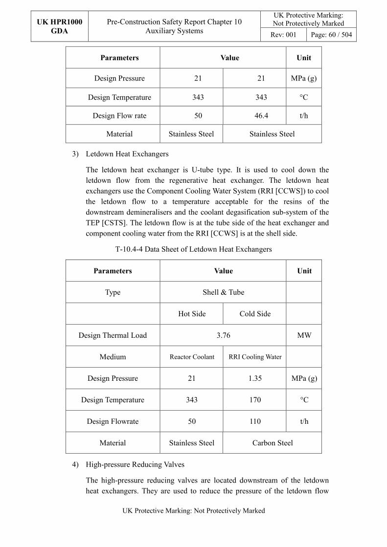
UK HPR1000
GDA
Pre-Construction Safety Report Chapter 10 Auxiliary Systems
UK Protective Marking: Not Protectively Marked
Rev: 001 Page: 60 / 504
UK Protective Marking: Not Protectively Marked
Parameters Value Unit
Design Pressure 21 21 MPa (g)
Design Temperature 343 343 °C
Design Flow rate 50 46.4 t/h
Material Stainless Steel Stainless Steel
3) Letdown Heat Exchangers
The letdown heat exchanger is U-tube type. It is used to cool down the letdown flow from the regenerative heat exchanger. The letdown heat exchangers use the Component Cooling Water System (RRI [CCWS]) to cool the letdown flow to a temperature acceptable for the resins of the downstream demineralisers and the coolant degasification sub-system of the TEP [CSTS]. The letdown flow is at the tube side of the heat exchanger and component cooling water from the RRI [CCWS] is at the shell side.
T-10.4-4 Data Sheet of Letdown Heat Exchangers
Parameters Value Unit
Type Shell & Tube
Hot Side Cold Side
Design Thermal Load 3.76 MW
Medium Reactor Coolant RRI Cooling Water
Design Pressure 21 1.35 MPa (g)
Design Temperature 343 170 °C
Design Flowrate 50 110 t/h
Material Stainless Steel Carbon Steel
4) High-pressure Reducing Valves
The high-pressure reducing valves are located downstream of the letdown heat exchangers. They are used to reduce the pressure of the letdown flow
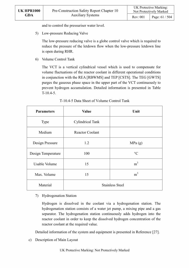
UK HPR1000
GDA
Pre-Construction Safety Report Chapter 10 Auxiliary Systems
UK Protective Marking: Not Protectively Marked
Rev: 001 Page: 61 / 504
UK Protective Marking: Not Protectively Marked
and to control the pressuriser water level.
5) Low-pressure Reducing Valve
The low-pressure reducing valve is a globe control valve which is required to reduce the pressure of the letdown flow when the low-pressure letdown line is open during RHR.
6) Volume Control Tank
The VCT is a vertical cylindrical vessel which is used to compensate for volume fluctuations of the reactor coolant in different operational conditions in conjunction with the REA [RBWMS] and TEP [CSTS]. The TEG [GWTS] purges the gaseous phase space in the upper part of the VCT continuously to prevent hydrogen accumulation. Detailed information is presented in Table T-10.4-5.
T-10.4-5 Data Sheet of Volume Control Tank
Parameters Value Unit
Type Cylindrical Tank
Medium Reactor Coolant
Design Pressure 1.2 MPa (g)
Design Temperature 100 °C
Usable Volume 15 m3
Max. Volume 15 m3
Material Stainless Steel
7) Hydrogenation Station
Hydrogen is dissolved in the coolant via a hydrogenation station. The hydrogenation station consists of a water jet pump, a mixing pipe and a gas separator. The hydrogenation station continuously adds hydrogen into the reactor coolant in order to keep the dissolved hydrogen concentration of the reactor coolant at the required value.
Detailed information of the system and equipment is presented in Reference [27].
c) Description of Main Layout
UK HPR1000
GDA
Pre-Construction Safety Report Chapter 10 Auxiliary Systems
UK Protective Marking: Not Protectively Marked
Rev: 001 Page: 62 / 504
UK Protective Marking: Not Protectively Marked
The regenerative heat exchanger, letdown heat exchangers and high-pressure reducing valves, their associated letdown and charging pipelines connected with RCP [RCS], are located in the Reactor Building (BRX). The coolant purification unit is located in the Nuclear Auxiliary Building (BNX). The other parts of the RCV [CVCS] are located in the Fuel Building (BFX).
Detailed information can be found in Reference [28].
d) Description of System Interfaces
The main interfacing systems which support the RCV [CVCS] functions are:
1) REA [RBWMS]
The REA [RBWMS] is required to provide automatic makeup of boric acid of the same concentration as the primary coolant when the volume control tank level falls to a low-level set value and regulate the coolant boron concentration by makeup of boric acid or demineralised water according to the requirements of reactivity control.
2) RRI [CCWS]
The RRI [CCWS] is required to provide component cooling water for the letdown heat exchangers and the charging pumps motors.
3) TEP [CSTS]
The TEP [CSTS] is required to remove the dissolved gas in the reactor coolant and discharge the excess reactor coolant into the reactor coolant storages when needed.
4) TEG [GWTS]
The TEG [GWTS] is required to continuously purge the volume control tank by removing the fission gas.
5) RIS [SIS]
The RIS [SIS] guarantees the letdown function through the low-pressure letdown line connecting the RIS [SIS] in RHR mode to the RCV [CVCS] system. It also provides In-Containment Refuelling Water Storage Tank (IRWST) water intake for the RCV [CVCS] charging pumps. The RIS [SIS] guarantees purification of the reactor coolant through the RIS-RCV connection line in case the primary pressure is low.
6) EHR [CHRS]
The EHR [CHRS] provides the suction pipe for the charging pumps to take suction from the IRWST and returns the small flow rate of the charging pumps and the seal leak-off through the EHR [CHRS] line back to the
UK HPR1000
GDA
Pre-Construction Safety Report Chapter 10 Auxiliary Systems
UK Protective Marking: Not Protectively Marked
Rev: 001 Page: 63 / 504
UK Protective Marking: Not Protectively Marked
IRWST when the charging pumps take water from the IRWST.
7) KRT [PRMS]
The KRT [PRMS] detects activity at the inlet and outlet of each letdown heat exchanger on the RRI [CCWS] side to identify heat exchanger tube leaks.
Other interfacing systems are presented in the SDM, Reference [27].
e) Description of Instrumentation and Control
Instrumentation is designed to monitor and control the main parameters of the RCV [CVCS]. The main parameters include temperature, pressure, flow, water level, hydrogen concentration and radioactivity.
The RCV [CVCS] has the following main control functions:
1) PZR level control function by regulating the letdown flow;
2) The seal injection flow control function of the reactor coolant pumps of the RCP [RCS];
3) The seal leak-off pressure control function of the reactor coolant pumps of the RCP [RCS];
4) The pressure control function downstream the high-pressure reducing valves;
5) The temperature control function of the letdown flow;
6) The water level control of the VCT;
7) The pressure control of the VCT;
8) The water level control of the gas separator;
9) The charging flow control function.
Detailed system control functional requirements are presented in the SDM for RCV [CVCS], Reference [29]. The design of the UK HPR1000 I&C system is presented in PCSR Chapter 8.
10.4.3.4.2 System Operation
a) Plant Normal Conditions
1) Plant Start-up
During plant start-up, the reactor coolant enters the purification unit through the low-pressure letdown line to remove corrosion products, and is also sent to the coolant degassing unit to remove oxygen from the reactor coolant.
Before the reactor coolant temperature reaches 120 °C, 7LiOH and hydrazine can be added to the reactor coolant to control the pH value and
UK HPR1000
GDA
Pre-Construction Safety Report Chapter 10 Auxiliary Systems
UK Protective Marking: Not Protectively Marked
Rev: 001 Page: 64 / 504
UK Protective Marking: Not Protectively Marked
deoxygenation.
When the chemical properties of the reactor coolant meet the chemical requirements, the hydrogenation station is started so as to reach and maintain the required dissolved hydrogen concentration in the reactor coolant which is used to control the dissolved oxygen content during power operation.
During plant start-up, the excess coolant resulting from the expansion of the heating will be discharged to the TEP [CSTS] coolant storage unit.
The boric acid and demineralized water makeup lines of the Reactor Boron and Water Makeup System (REA [RBWMS]) are put into operation according to the requirement of boron concentration regulation.
During plant start-up, the RCV [CVCS] maintains the pressurizer level by letdown and charging, and continuously provides seal injection water for the reactor coolant pumps.
2) Normal Power Operation
During normal power operation, the regenerative heat exchanger, one letdown heat exchanger, one high-pressure reducing valve and one charging pump are in operation. The letdown flow is routed out of the reactor building to the purification unit. One coolant filter, one mixed bed demineraliser and one resin trap filter are in operation. If needed, a cation-bed demineraliser can be put into intermittent operation as necessary to remove excess lithium, caesium, molybdenum and ytterbium in the reactor coolant. According to the need, fission gas (such as krypton and xenon) in the reactor coolant can be removed by the coolant degassing unit of the Coolant Storage and Treatment System (TEP [CSTS]) system, and the hydrogen and nitrogen in the coolant will be removed together.
After purification and degassing, the hydrogenation station continuously adds hydrogen into the reactor coolant so as to keep the dissolved hydrogen concentration in the coolant at the required value. Part of the letdown flow and the reactor coolant pump seal leak-off water will flow into the VCT to ensure the boron concentration in the VCT is the same as the primary coolant.
During normal operation, 7LiOH can be injected into the reactor coolant upstream of the charging pump by chemical injection pump as needed for pH control.
The reactor coolant is sent back to the RCP [RCS] by charging pump, and a bypass flow is used as reactor coolant pump seal injection. The seal injection water flow of each reactor coolant pump is the same.
UK HPR1000
GDA
Pre-Construction Safety Report Chapter 10 Auxiliary Systems
UK Protective Marking: Not Protectively Marked
Rev: 001 Page: 65 / 504
UK Protective Marking: Not Protectively Marked
During normal operation, the pressurizer auxiliary spray line is isolated.
In normal operation, if it is necessary to improve the reactor coolant purification and degassing efficiency, or adjust the reactor coolant boron concentration, the second charging pump can be put into operation as needed.
In order to compensate for fuel burn-up, the boron concentration is adjusted by the RCV [CVCS] in conjunction with the REA [RBWMS] which provides the make-up demineralised water to the VCT.
The VCT level may change if the charging flow and letdown flow dis-match. In order to make sure that the VCT level is at the normal value, a part of or all of the letdown flow is discharged to the TEP [CSTS] when the VCT level reaches a high value, while the REA [RBWMS] provides the make-up boric acid solution of the same concentration as the reactor coolant to the VCT when the VCT level reaches a low value.
3) Plant shutdown
During plant shutdown, depending on the reactor coolant purification or degassing requirements, as well as compensating for volume fluctuation caused by reactor coolant shrinkage, the RCV [CVCS] high-pressure letdown line remains normally open until the pressurizer is relieved. The two letdown heat exchangers, two high-pressure reducing valves and two charging pumps are all put into operation.
When the RIS [SIS] in RHR mode is connected to the RCP [RCS], the residual heat is removed by RIS/RHR. When the temperature and pressure of the RCP [RCS] is low enough, the high-pressure letdown line is isolated and the letdown function is switched to the low-pressure letdown line. The reactor coolant still returns to the RCP [RCS] through the normal charging line.
During cooling and depressurization, according to the requirement of boron concentration regulation, the boric acid and demineralized water makeup lines of the REA [RBWMS] will provide the boric acid for the RCV [CVCS], which will inject into the RCP [RCS] eventually. The excess coolant will be discharged to the TEP [CSTS] coolant storage unit.
After the complete depressurization of the primary loop, the charging pumps may be shut down, and the reactor coolant pump seal injection water is maintained by the RIS/RHR pumps.
b) Plant Accident Conditions
The RCV [CVCS] can be used in accident conditions if there is no safety-classified isolation signal (e.g. safety injection and containment isolation).
UK HPR1000
GDA
Pre-Construction Safety Report Chapter 10 Auxiliary Systems
UK Protective Marking: Not Protectively Marked
Rev: 001 Page: 66 / 504
UK Protective Marking: Not Protectively Marked
The RCV [CVCS] can operate even in a Loss of Offsite Power (LOOP) condition as the electric components required are powered by EDGs (Emergency Diesel Generators). When the reactor coolant pumps stop due to LOOP, the RCV [CVCS] can provide auxiliary spray for the pressuriser.
The VCT and hydrogenation station will be isolated automatically and the suction line of the charging pumps is switched to IRWST automatically at the dilution protection signal. Letdown flow is drained to the TEP [CSTS] if the VCT level reaches a high value. The mini flow line of the charging pumps and the seal leak-off flow line from the RCP [RCS] reactor coolant pumps are switched to the IRWST.
Detailed information of the operation of the RCV [CVCS] is presented in the SDM of RCV [CVCS], Reference [29].
10.4.3.5 Preliminary Design Substantiation
In this section, the system design is demonstrated to satisfy the safety functional requirements presented in Sub-chapter 10.4.3.1 and the general design requirements stated in Sub-chapter 10.2.4. Review of the consistency of the system design against the newly developed principles is currently being undertaken.
10.4.3.5.1 Compliance with Safety Functional Requirements
The system configuration and the capability of the components comply with the safety functional requirements and the detailed design of the system is presented in the SDM [30], [27] and [29]. Furthermore, design substantiation of the RCV [CVCS] has been estimated in the fault study in Chapters 12 and 13.
a) Control of Reactivity
1) The RCV [CVCS] regulates reactor activity by controlling the boron concentration of the RCP [RCS] in conjunction with the REA [RBWMS]. The letdown and charging flow rate can meet the requirements of reactor activity control. When the REA [RBWMS] fails, the charging pumps suction line can be switched to the IRWST.
2) Two safety classified isolation valves in series are provided on each charging pump suction line from either the VCT or hydrogenation station. The closing time of the anti-dilution isolation valves is designed to be less than or equal to 30s, this is evaluated in the fault analysis, presented in Chapter 12.
b) Removal of Heat
1) In plant normal operations, the RCV [CVCS] can adjust the balance between the charging flow rate and the letdown flow rate to control the water inventory of the RCP [RCS], thus the fuel can be cooled suitably.
UK HPR1000
GDA
Pre-Construction Safety Report Chapter 10 Auxiliary Systems
UK Protective Marking: Not Protectively Marked
Rev: 001 Page: 67 / 504
UK Protective Marking: Not Protectively Marked
2) In post accidental conditions, the RCV [CVCS] system can participate in maintaining primary coolant inventory by automatic isolation of the letdown line.
c) Confinement
1) Redundant isolation valves are installed in series to ensure automatic containment isolation in accident conditions when receiving the containment isolation signals;
2) Redundant isolation valves are installed in series to ensure RCPB isolation in accident conditions when receiving the RCPB isolation signals;
3) The RCV [CVCS] can supply cooled and purified seal water to the reactor coolant pumps to prevent the reactor coolant from leaking through the seal of the reactor coolant pumps to reduce radioactivity release;
4) The RCV [CVCS] can provide auxiliary spray for the pressuriser automatically or manually to protect the pressuriser from overpressure;
5) In SGTR accidents, the charging line and the auxiliary spray line will be isolated automatically to avoid overflowing of the affected SGs and prevent leakage at break points to reduce radioactivity release;
d) Extra Safety Functions
1) The hydrogen supply line to the gas separator is designed to be isolated automatically after receiving a protection signal from the Nuclear Island Hydrogen Detection System (KRH (HDS)) when a leak is detected;
2) To ensure that the cooling functions of higher-classified users of the RRI [CCWS] are not affected by the failure of integrity of components and lines associated with the RRI [CCWS], radioactivity detecting instruments are designed on the shell side of the heat exchanger of the RCV [CVCS]. When a leak is detected, the heat exchanger can be isolated to prevent radioactivity release to the RRI [CCWS];
3) When the temperature downstream of the letdown heat exchanger has reached 90°C, the isolation valve downstream of the high-pressure reducing valve will be automatically closed to prevent the temperature of the containment penetration from exceeding its limits;
4) In the event of the excessive rise in the secondary steam flow rate, especially steam line break accident, the RCV [CVCS] can automatically isolate the charging line and auxiliary spray line to guarantee that the safety injection system (RIS [SIS]) is able to provide sufficient boric acid to assure core sub-critical.
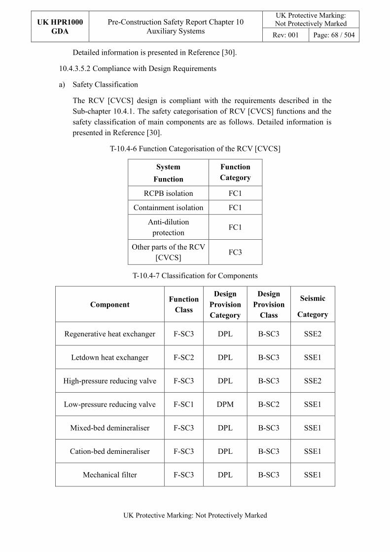
UK HPR1000
GDA
Pre-Construction Safety Report Chapter 10 Auxiliary Systems
UK Protective Marking: Not Protectively Marked
Rev: 001 Page: 68 / 504
UK Protective Marking: Not Protectively Marked
Detailed information is presented in Reference [30].
10.4.3.5.2 Compliance with Design Requirements
a) Safety Classification
The RCV [CVCS] design is compliant with the requirements described in the Sub-chapter 10.4.1. The safety categorisation of RCV [CVCS] functions and the safety classification of main components are as follows. Detailed information is presented in Reference [30].
T-10.4-6 Function Categorisation of the RCV [CVCS]
System
Function
Function
Category
RCPB isolation FC1
Containment isolation FC1
Anti-dilution protection
FC1
Other parts of the RCV [CVCS]
FC3
T-10.4-7 Classification for Components
Component Function
Class
Design
Provision
Category
Design
Provision
Class
Seismic
Category
Regenerative heat exchanger F-SC3 DPL B-SC3 SSE2
Letdown heat exchanger F-SC2 DPL B-SC3 SSE1
High-pressure reducing valve F-SC3 DPL B-SC3 SSE2
Low-pressure reducing valve F-SC1 DPM B-SC2 SSE1
Mixed-bed demineraliser F-SC3 DPL B-SC3 SSE1
Cation-bed demineraliser F-SC3 DPL B-SC3 SSE1
Mechanical filter F-SC3 DPL B-SC3 SSE1
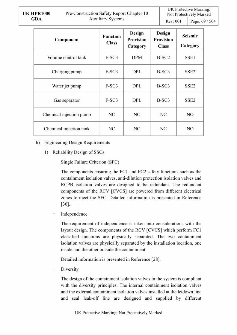
UK HPR1000
GDA
Pre-Construction Safety Report Chapter 10 Auxiliary Systems
UK Protective Marking: Not Protectively Marked
Rev: 001 Page: 69 / 504
UK Protective Marking: Not Protectively Marked
Component Function
Class
Design
Provision
Category
Design
Provision
Class
Seismic
Category
Volume control tank F-SC3 DPM B-SC2 SSE1
Charging pump F-SC3 DPL B-SC3 SSE2
Water jet pump F-SC3 DPL B-SC3 SSE2
Gas separator F-SC3 DPL B-SC3 SSE2
Chemical injection pump NC NC NC NO
Chemical injection tank NC NC NC NO
b) Engineering Design Requirements
1) Reliability Design of SSCs
- Single Failure Criterion (SFC)
The components ensuring the FC1 and FC2 safety functions such as the containment isolation valves, anti-dilution protection isolation valves and RCPB isolation valves are designed to be redundant. The redundant components of the RCV [CVCS] are powered from different electrical zones to meet the SFC. Detailed information is presented in Reference [30].
- Independence
The requirement of independence is taken into considerations with the layout design. The components of the RCV [CVCS] which perform FC1 classified functions are physically separated. The two containment isolation valves are physically separated by the installation location, one inside and the other outside the containment.
Detailed information is presented in Reference [28].
- Diversity
The design of the containment isolation valves in the system is compliant with the diversity principles. The internal containment isolation valves and the external containment isolation valves installed at the letdown line and seal leak-off line are designed and supplied by different
UK HPR1000
GDA
Pre-Construction Safety Report Chapter 10 Auxiliary Systems
UK Protective Marking: Not Protectively Marked
Rev: 001 Page: 70 / 504
UK Protective Marking: Not Protectively Marked
manufacturers; the internal containment isolation valves are designed as a check valve, while the external containment isolation valves are designed as a shut-off valve.
- Fail-safe
The methodology and analysis of the fail-safe design in the RCV [CVCS] system is presented in the Reference [27]. After comprehensive analysis, the means of “fail-safe” design do not meet the specific safety consideration, therefore measures other than the fail-safe design such as redundancy are used to improve the safety in order to avoid the potential safety risks that may be introduced by “fail-safe” design on a power plant.
- Ageing and Degradation
According to Chapter 2, the plant design life is 60 years. The service life of some main components is 60 years. For example, the regenerative heat exchanger, the letdown heat exchangers, the volume control tank, the charging pumps, etc.
The RCV [CVCS] system considers the requirements stated in Sub-chapter 10.2.4 and the design considerations and measures described in Sub-chapter 10.2.4 are applied in the design of the RCV [CVCS] system.
Detailed design arrangement around Examination, Maintenance, Inspection and Testing (EMIT) and equipment monitoring is presented in the SDM, Reference [29].
2) Autonomy
- Autonomy with respect to Operators
The design principles relevant to the autonomy with respect to operators are detailed in Sub-chapter 10.2.4. The RCV [CVCS] does not require short term operator intervention after a dilution accident. Detailed information is presented in the SDM, Reference [29]. The design result is estimated in the safety analysis.
- Autonomy with respect to the Heat Sink
Not applicable.
- Autonomy with respect to Power Supply Systems
The redundancy valves of the RCV [CVCS] system performing FC1 and FC2 classified isolation functions are powered by the emergency power supply and meet the single failure criterion. Therefore, the redundancy
UK HPR1000
GDA
Pre-Construction Safety Report Chapter 10 Auxiliary Systems
UK Protective Marking: Not Protectively Marked
Rev: 001 Page: 71 / 504
UK Protective Marking: Not Protectively Marked
valves are powered by different electrical zones.
In addition, the containment isolation valves inside the containment of the RCV [CVCS] system are required to be powered by the Station Black Out (SBO) diesel generators and 2h batteries. The containment isolation valves outside the containment are required to be powered by the SBO diesel generators and 24h severe accident batteries.
Power supply requirements of the components performing safety functions are identified in Reference [29].
3) Other Design Requirements
- Prevention of Harmful Interactions of Systems Important to Safety
� Provisions have been made to prevent the design pressure of the system operating at the lower pressure from being exceeded. Adequate isolation (e.g. using double isolating valves) and appropriate control functions between the RCV [CVCS] and interfacing systems are designed to protect the interfacing system from overpressure, Reference [27];
� Provisions have been made to prevent radioactivity from being released to supporting systems. Radioactivity detecting instruments are designed on the shell side of the heat exchanger of the RCV [CVCS]. When a leak is detected, the heat exchanger can be isolated to prevent radioactivity release to the RRI [CCWS], Reference [27];
- Considerations Related to the Electrical Power Grid
The function of the charging pump of the RCV [CVCS] could be disturbed by the fluctuations of the electrical power grid. In this case, two charging pumps may be put into operation to compensate for the possible lack of flowrate when required. The functional reliability of the main valves shall be substantiated by the equipment vendor to take the electrical power grid fluctuation into account.
c) Equipment Qualification
The requirements concerning equipment qualification are presented in Chapter 4. The design of the RCV [CVCS] complies with these requirements.
Active components of the RCV [CVCS] that perform FC1 or FC2 safety functions, such as the containment isolation valves, anti-dilution protection isolation valves, RCPB isolation valves, shall be qualified. Active components of the RCV [CVCS] that perform FC3 safety functions required under DEC conditions shall be qualified. All the seismic classified components of the RCV [CVCS] shall be available during and after the SSE.
UK HPR1000
GDA
Pre-Construction Safety Report Chapter 10 Auxiliary Systems
UK Protective Marking: Not Protectively Marked
Rev: 001 Page: 72 / 504
UK Protective Marking: Not Protectively Marked
Principles of equipment qualification classification of the system are presented in Reference [30]. Detailed information related to the system equipment qualification is presented in Reference [27].
d) Protection Design against Internal and External Hazards
The RCV [CVCS] system considers the requirements stated in Sub-chapter 10.2.4. The RCV [CVCS] is required to be protected against several external and internal hazards, and the corresponding protection measures are described below.
1) External hazards
- Earthquake
The components of the RCV [CVCS] which perform the FC1 and FC2 safety functions are arranged in SSE1-classified structures, for which seismic loads of Safe Shutdown Earthquake (SSE) is considered during design.
- Other external hazards
The RVC [CVCS] protects against external disasters mainly through the building design. Specific protection design is presented in Reference [28].
2) Internal hazards
For RCV [CVCS] components, separation and different elevation are applied to eliminate or minimize CCF induced by internal hazards. According to the characteristics and configuration of RCV [CVCS], the components of RCV [CVCS] are distributed in BRX, BFX and BNX. The specific protection design is presented in Reference [28].
e) Commissioning
Commissioning and tests will be carried out for the RCV [CVCS] to validate its functionality. The methodology of system commissioning programme design is presented in Reference [31]. Further detailed site specific arrangements for the UK HPR1000 commissioning activities will be presented during the nuclear site licencing phase.
f) Examination, Inspection, Maintenance and Testing
1) Inspections and Surveillances
In-service inspection is required for a number of components and pipelines of the RCV [CVCS] in order to maintain a satisfactory safety level for components enduring sustained pressure.
According to the RSE-M code, equipment and lines belonging to the main
UK HPR1000
GDA
Pre-Construction Safety Report Chapter 10 Auxiliary Systems
UK Protective Marking: Not Protectively Marked
Rev: 001 Page: 73 / 504
UK Protective Marking: Not Protectively Marked
primary loop require in-service inspection and pre-inspection, i.e. the equipment and pipelines within the RCPB isolation boundary.
The RCV [CVCS] is designed with a range of surveillance methods to monitor system configuration status in real time, so as to help the operators to keep abreast of the system operating status and intervene if an abnormal event occurs to ensure the safety operation of the system.
The main monitoring methods of the RCV [CVCS] are described below:
- The surveillance of the high-pressure letdown line operation status;
- The surveillance of the low-pressure letdown line operation status;
- The surveillance of the charging line operation status;
- The surveillance of the seal injection line operation status;
- The surveillance of the seal leak-off line operation status;
- The surveillance of the auxiliary spray line operation status.
Equipment of RCV [CVCS] requiring periodic maintenance must be provided with enough maintenance space, especially the heat exchangers, charging pumps, safety valves and control valves.
2) Maintenance
The system layout considers the convenience of maintenance operations and reducing the irradiation dose to workers to an acceptable level. When the main equipment is being repaired, it is necessary to facilitate the draining and venting after isolation.
Maintenance of the main equipment of the RCV [CVCS] is carried out during the refuelling cold shutdown. The maintenance and replacement of the RCV [CVCS] mainly includes the following:
- The maintenance of the heat exchangers;
- The maintenance of the pumps and valves;
- The maintenance of the VCT;
- The maintenance and replacement of the demineralisers;
- The maintenance and replacement of the filters.
3) Periodic Tests
The system design must ensure the feasibility of testing and in-service inspection, especially for the equipment which needs to be put into operation after an earthquake.
UK HPR1000
GDA
Pre-Construction Safety Report Chapter 10 Auxiliary Systems
UK Protective Marking: Not Protectively Marked
Rev: 001 Page: 74 / 504
UK Protective Marking: Not Protectively Marked
The equipment performing FC1-classified and FC2-classified safety functions and those that perform FC3-classified safety functions but are not required to operate continuously must be tested.
The parts of the RCV [CVCS] which are not safety related also need to be tested, such as the safety valves.
The safety functions required for periodic testing of the RCV [CVCS] are as follows:
- The isolation downstream of the VCT and hydrogenation station;
- The isolation of the charging line and the auxiliary spray line;
- The isolation of the high-pressure letdown line;
- The isolation of the seal injection line;
- The isolation of the containment;
- The isolation of the RCPB.
For equipment operating during the full fuel cycle, it is not required to carry out periodic testing, as their availability has been checked during normal operation.
For the equipment not operating during the fuel cycle, its availability must be checked by periodic testing.
For the UK HPR1000, the periodic test design method is presented in the Reference [32].
g) Decommissioning
The design of the RCV [CVCS] considers decommissioning. A certain gradient is set in the pipeline layout to prevent liquid accumulation and all equipment and pipes can be drained by the draining lines.
h) Material Selection
The metal parts of the RCV [CVCS] system that convey borated water during operation must be made of austenitic stainless steel in order to limit corrosion.
i) Special Thermal-hydraulic Phenomena
In order to ensure the functional reliability of the system and to prevent challenges in performing the safety functions, the hydraulic phenomena listed below are carefully considered in RCV [CVCS] design:
1) Phenomenon regarding the dead leg;
2) Phenomenon regarding the hot water and cold water mixing;
UK HPR1000
GDA
Pre-Construction Safety Report Chapter 10 Auxiliary Systems
UK Protective Marking: Not Protectively Marked
Rev: 001 Page: 75 / 504
UK Protective Marking: Not Protectively Marked
3) Phenomenon regarding the thermal stratification;
4) Phenomenon regarding the water hammer.
j) Insulation
The pipes and components containing fluid with a temperature more than 60°C in normal operating conditions need insulation design to protect the workers. This includes the charging line, seal injection line, seal leak-off line and the letdown heat exchanger upstream line.
k) Human Factors
The RCV [CVCS] system considers the requirements stated in Sub-chapter 10.2.4 and the design considerations and measures described in Sub-chapter 10.2.4 are applied in the design of the RCV [CVCS] system.
The RCV [CVCS] does not require short term operator intervention after a dilution accident. Detailed information about automatic control design of the system is presented in the SDM, Reference [29].
10.4.3.6 Simplified Diagrams
The simplified system functional diagram is presented in Figure F-10.4-1; the detailed system functional diagram is in Reference [33].
10.4.4 Reactor Boron and Water Makeup System (REA [RBWMS])
REA [RBWMS] controls the reactivity of the core by adjusting the boron concentration in the RCP [RCS] via the RCV [CVCS] under normal conditions, and compensates for reactivity change in the core along with the control rods during unit start-up / shutdown and burn-up change. System information is presented in the SDM, Reference [34].
10.4.4.1 Safety Functional Requirements
10.4.4.1.1 Control of Reactivity
The REA [RBWMS] contributes to the control of reactivity by performing the following functions:
a) The REA [RBWMS] shall protect the reactor from the risk of spurious dilution caused by the REA [RBWMS] in plant normal operating conditions;
b) The REA [RBWMS] shall provide borated makeup water to the RCP [RCS] via the RCV [CVCS] to control the boron concentration in the RCP [RCS] and compensate for the slow reactivity change in plant normal operating conditions;
c) The REA [RBWMS] shall ensure adjustment of the boron concentration in the RCP [RCS] and VCT level by providing borated water makeup in the event of
UK HPR1000
GDA
Pre-Construction Safety Report Chapter 10 Auxiliary Systems
UK Protective Marking: Not Protectively Marked
Rev: 001 Page: 76 / 504
UK Protective Marking: Not Protectively Marked
short term loss of offsite power conditions (DBC-2).
10.4.4.1.2 Removal of Heat
The REA [RBWMS] does not directly contribute to the removal of heat function.
10.4.4.1.3 Confinement
The part of the REA [RBWMS] containing radioactive substances shall ensure the confinement of radioactive substances and prevent radioactivity release.
10.4.4.1.4 Extra Safety Functions
The REA [RBWMS] does not indirectly contribute to the three safety functions.
10.4.4.2 Design Requirements
The general design requirements of the nuclear auxiliary systems which need to be considered are shown in Sub-chapter 10.2.4, among which the following requirements are not applicable for the REA [RBWMS] system:
a) Single Failure Criterion (SFC)
Not applicable, because the REA [RBWMS] system doesn’t perform safety functions of category FC1.
b) Diversity
Not applicable. There’s no diversity design in the REA [RBWMS].
c) Autonomy with respect to Heat Sink
Not applicable, because the REA [RBWMS] doesn’t provide a heat sink to the power plant.
The substantiation analysis of the REA [RBWMS] to other design requirements is shown in Sub-chapter 10.4.4.5.
10.4.4.3 Design Bases
This sub-chapter aims to provide the main design assumptions considered in the system design.
10.4.4.3.1 General Assumptions
a) Safety Classification
The boric acid storage and injection function, and the demineralised water injection function are required to control the boron concentration in the primary loop within a suitable range during normal operating conditions and DBC-2 conditions (in the event of short term LOOP (< 2 hours)), the function category is FC3.
UK HPR1000
GDA
Pre-Construction Safety Report Chapter 10 Auxiliary Systems
UK Protective Marking: Not Protectively Marked
Rev: 001 Page: 77 / 504
UK Protective Marking: Not Protectively Marked
The demineralised water restriction function is required to restrict the flowrate of demineralised water injecting into the primary loop when unexpected dilution happens, the function category is FC3.
The confinement of radioactive substances function is required to prevent radioactivity release in all conditions, the function category is FC3.
b) Ageing and Degradation
The main components of the REA [RBWMS] are required to have a service life of 60 years.
c) Considerations Related to the Electrical Power Grid
The functionality of items important to safety at the nuclear power plant shall not be compromised by disturbances in the electrical power grid, including anticipated variations in the voltage and frequency of the grid supply. In the REA [RRBWMS] design, the flowrate of the boric acid injection pump and the demineralised water injection pump can be influenced by the fluctuation of the power grid; this effect has been evaluated in the design. The information related to the grid connection is presented in Chapter 3.
10.4.4.3.2 Design Assumptions
a) Control of Reactivity
The REA [RBWMS] is required to fulfil the safety functional requirements with the following design assumptions:
1) To avoid unexpected dilution accidents in normal operation, the flowrate of demineralised water injection shall be restricted, to give enough time for the operator to take appropriate corrective actions (at least 30 minutes).
2) The boric acid storage tank capacity is sufficient to bring the reactor to cold shutdown from power operation at the beginning of life and after a shutdown for refuelling at end of life, without recovering of boric acid from the TEP [CSTS];
3) To ensure the adjustment of the boron concentration in the RCP [RCS] and VCT level in DBC-2 condition of short term LOOP (less than 2 hours), the REA [RBWMS] shall provide borated makeup water.
b) Removal of Heat
Not applicable. The REA [RBWMS] system does not directly contribute to the safety function of removal of heat.
c) Confinement
Not applicable. There’s no quantitative safety-related design assumption for the
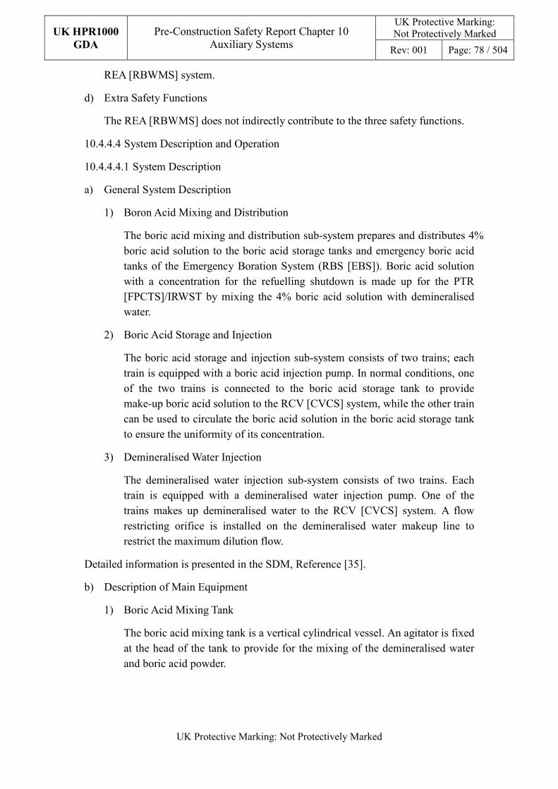
UK HPR1000
GDA
Pre-Construction Safety Report Chapter 10 Auxiliary Systems
UK Protective Marking: Not Protectively Marked
Rev: 001 Page: 78 / 504
UK Protective Marking: Not Protectively Marked
REA [RBWMS] system.
d) Extra Safety Functions
The REA [RBWMS] does not indirectly contribute to the three safety functions.
10.4.4.4 System Description and Operation
10.4.4.4.1 System Description
a) General System Description
1) Boron Acid Mixing and Distribution
The boric acid mixing and distribution sub-system prepares and distributes 4% boric acid solution to the boric acid storage tanks and emergency boric acid tanks of the Emergency Boration System (RBS [EBS]). Boric acid solution with a concentration for the refuelling shutdown is made up for the PTR [FPCTS]/IRWST by mixing the 4% boric acid solution with demineralised water.
2) Boric Acid Storage and Injection
The boric acid storage and injection sub-system consists of two trains; each train is equipped with a boric acid injection pump. In normal conditions, one of the two trains is connected to the boric acid storage tank to provide make-up boric acid solution to the RCV [CVCS] system, while the other train can be used to circulate the boric acid solution in the boric acid storage tank to ensure the uniformity of its concentration.
3) Demineralised Water Injection
The demineralised water injection sub-system consists of two trains. Each train is equipped with a demineralised water injection pump. One of the trains makes up demineralised water to the RCV [CVCS] system. A flow restricting orifice is installed on the demineralised water makeup line to restrict the maximum dilution flow.
Detailed information is presented in the SDM, Reference [35].
b) Description of Main Equipment
1) Boric Acid Mixing Tank
The boric acid mixing tank is a vertical cylindrical vessel. An agitator is fixed at the head of the tank to provide for the mixing of the demineralised water and boric acid powder.
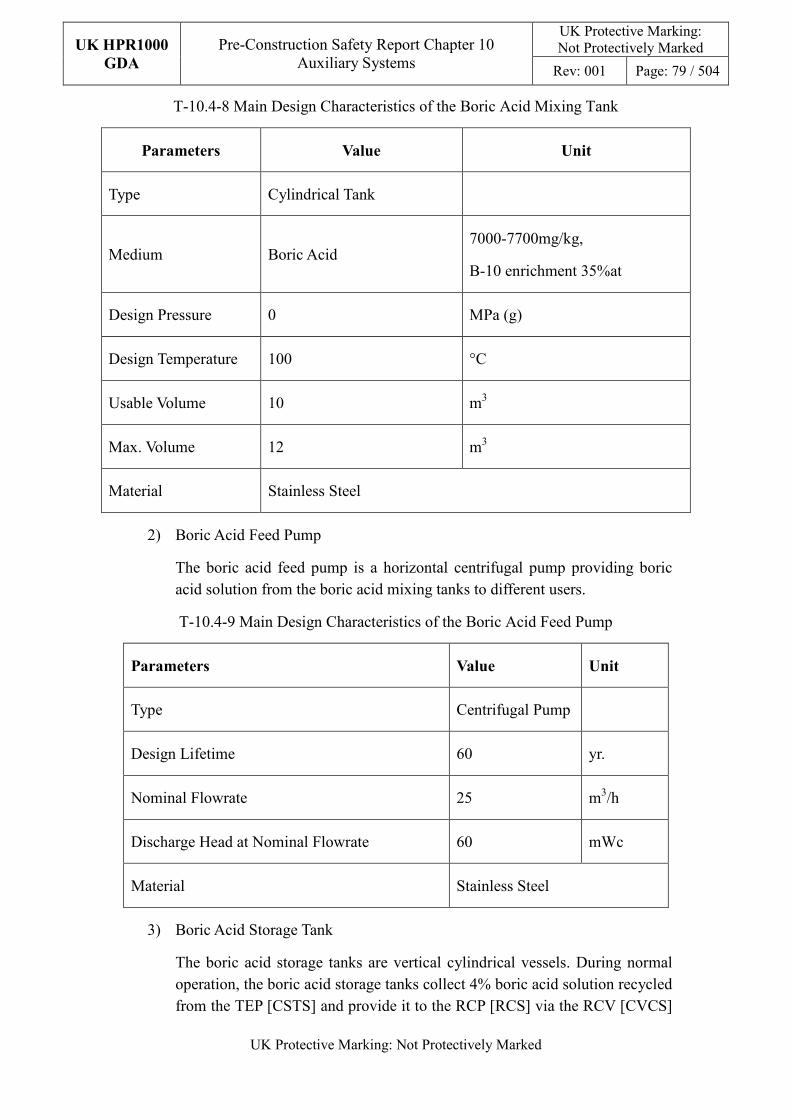
UK HPR1000
GDA
Pre-Construction Safety Report Chapter 10 Auxiliary Systems
UK Protective Marking: Not Protectively Marked
Rev: 001 Page: 79 / 504
UK Protective Marking: Not Protectively Marked
T-10.4-8 Main Design Characteristics of the Boric Acid Mixing Tank
Parameters Value Unit
Type Cylindrical Tank
Medium Boric Acid 7000-7700mg/kg,
B-10 enrichment 35%at
Design Pressure 0 MPa (g)
Design Temperature 100 °C
Usable Volume 10 m3
Max. Volume 12 m3
Material Stainless Steel
2) Boric Acid Feed Pump
The boric acid feed pump is a horizontal centrifugal pump providing boric acid solution from the boric acid mixing tanks to different users.
T-10.4-9 Main Design Characteristics of the Boric Acid Feed Pump
Parameters Value Unit
Type Centrifugal Pump
Design Lifetime 60 yr.
Nominal Flowrate 25 m3/h
Discharge Head at Nominal Flowrate 60 mWc
Material Stainless Steel
3) Boric Acid Storage Tank
The boric acid storage tanks are vertical cylindrical vessels. During normal operation, the boric acid storage tanks collect 4% boric acid solution recycled from the TEP [CSTS] and provide it to the RCP [RCS] via the RCV [CVCS]
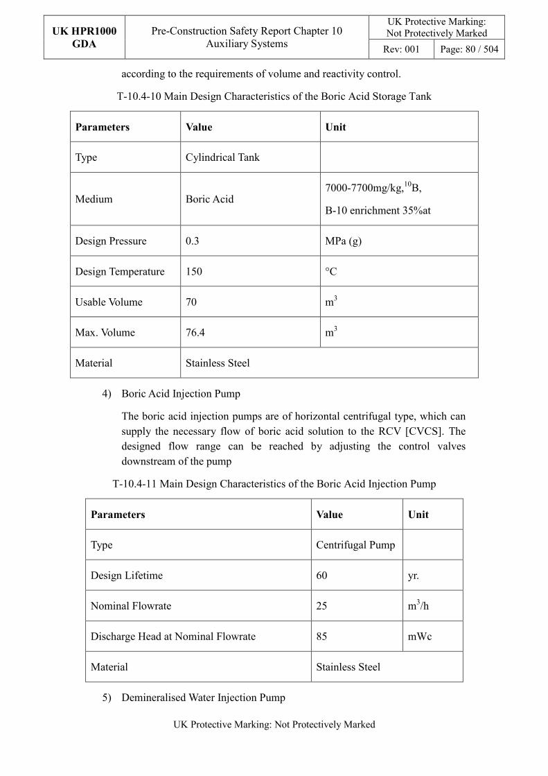
UK HPR1000
GDA
Pre-Construction Safety Report Chapter 10 Auxiliary Systems
UK Protective Marking: Not Protectively Marked
Rev: 001 Page: 80 / 504
UK Protective Marking: Not Protectively Marked
according to the requirements of volume and reactivity control.
T-10.4-10 Main Design Characteristics of the Boric Acid Storage Tank
Parameters Value Unit
Type Cylindrical Tank
Medium Boric Acid 7000-7700mg/kg,10B,
B-10 enrichment 35%at
Design Pressure 0.3 MPa (g)
Design Temperature 150 °C
Usable Volume 70 m3
Max. Volume 76.4 m3
Material Stainless Steel
4) Boric Acid Injection Pump
The boric acid injection pumps are of horizontal centrifugal type, which can supply the necessary flow of boric acid solution to the RCV [CVCS]. The designed flow range can be reached by adjusting the control valves downstream of the pump
T-10.4-11 Main Design Characteristics of the Boric Acid Injection Pump
Parameters Value Unit
Type Centrifugal Pump
Design Lifetime 60 yr.
Nominal Flowrate 25 m3/h
Discharge Head at Nominal Flowrate 85 mWc
Material Stainless Steel
5) Demineralised Water Injection Pump
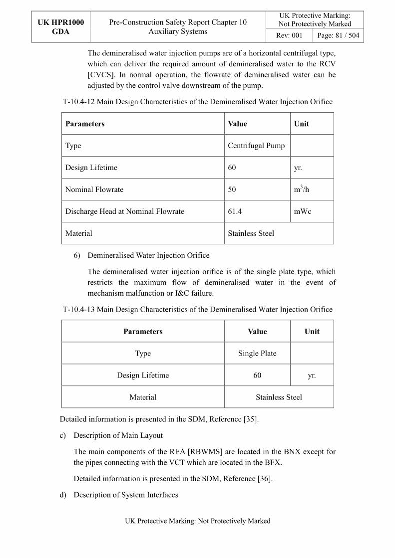
UK HPR1000
GDA
Pre-Construction Safety Report Chapter 10 Auxiliary Systems
UK Protective Marking: Not Protectively Marked
Rev: 001 Page: 81 / 504
UK Protective Marking: Not Protectively Marked
The demineralised water injection pumps are of a horizontal centrifugal type, which can deliver the required amount of demineralised water to the RCV [CVCS]. In normal operation, the flowrate of demineralised water can be adjusted by the control valve downstream of the pump.
T-10.4-12 Main Design Characteristics of the Demineralised Water Injection Orifice
Parameters Value Unit
Type Centrifugal Pump
Design Lifetime 60 yr.
Nominal Flowrate 50 m3/h
Discharge Head at Nominal Flowrate 61.4 mWc
Material Stainless Steel
6) Demineralised Water Injection Orifice
The demineralised water injection orifice is of the single plate type, which restricts the maximum flow of demineralised water in the event of mechanism malfunction or I&C failure.
T-10.4-13 Main Design Characteristics of the Demineralised Water Injection Orifice
Parameters Value Unit
Type Single Plate
Design Lifetime 60 yr.
Material Stainless Steel
Detailed information is presented in the SDM, Reference [35].
c) Description of Main Layout
The main components of the REA [RBWMS] are located in the BNX except for the pipes connecting with the VCT which are located in the BFX.
Detailed information is presented in the SDM, Reference [36].
d) Description of System Interfaces
UK HPR1000
GDA
Pre-Construction Safety Report Chapter 10 Auxiliary Systems
UK Protective Marking: Not Protectively Marked
Rev: 001 Page: 82 / 504
UK Protective Marking: Not Protectively Marked
The REA [RBWMS] system interfaces with the following systems:
1) Coolant Storage and Treatment System (TEP [CSTS])
During normal operation, the TEP [CSTS] provides 4% boric acid solution, retrieved by the evaporator, to the boric acid storage tanks.
The demineralised water injected to the RCV [CVCS] is suctioned from the TEP [CSTS] reactor coolant storage tanks.
2) Nuclear Sampling System (REN [NSS])
The REN [NSS] analyses the chemical parameters of the boric acid storage tanks inventory before it is injected to the RCV [CVCS].
Detailed information is presented in the SDM, Reference [35].
e) Description of Instrumentation and Control
Operators may select different operating modes according to the requirements of volume control and reactivity control:
1) Automatic Makeup
The start and stop of the automatic makeup are controlled according to level signals of the VCT.
The flowrate of demineralised water is set as a constant value, while the flowrate of boric acid solution is calculated automatically according to the boron concentrations of the boric acid in the storage tank and the primary coolant.
2) Boration
Boration is used to provide 7000mg/kg boric acid solution to the RCP [RCS] and to decrease reactivity of the reactor. Operators set the boric acid makeup flowrate and total volume in the main control room manually.
3) Dilution
Dilution is used to provide demineralised water to the RCP [RCS] to increase reactivity of the reactor. The flowrate and total volume of demineralised water are set by operators in the main control room manually.
4) Manual Makeup
Manual makeup applies to the following conditions:
- Filling the VCT;
- Makeup of the IRWST or SFP during plant normal operation.
UK HPR1000
GDA
Pre-Construction Safety Report Chapter 10 Auxiliary Systems
UK Protective Marking: Not Protectively Marked
Rev: 001 Page: 83 / 504
UK Protective Marking: Not Protectively Marked
Operators set demineralised water and boric acid makeup flowrate and total makeup volume according to the demands for boron concentration.
Detailed information is presented in the SDM, Reference [37].
10.4.4.4.2 System Operation
a) Plant Normal Conditions
1) Normal Steady-state Operation
- Power Operation
During power operation, the REA [RBWMS] generally operates in ‘automatic makeup’ mode to provide boric acid solution at the same boron concentration as the primary coolant, so as to compensate for minor leakage of reactor coolant.
- Hot Shutdown or Hot Standby
In hot shutdown or hot standby conditions, the REA [RBWMS] operates basically in the same manner as in power operation. If the duration of the hot shutdown is long, the boron concentration of coolant is regulated to compensate for reactivity changes caused by the xenon poisoning effect.
- RIS [SIS] Cooling Normal Shutdown or Maintenance Cold Shutdown
When three RCP [RCS] reactor coolant pumps of the RCP [RCS] system stop, the demineralised water makeup pipeline shall be isolated to isolate the dilution source of the REA [RBWMS]. The outlet of the boric acid injection pump can be switched to the IRWST to meet the makeup demands.
- Refuelling Cold Shutdown
In refuelling cold shutdown, the REA [RBWMS] will not be put into service to allow maintenance of all REA [RBWMS] components.
2) Normal Transient-state Operation
- Plant Start-up
During plant start-up, boric acid solution of the required concentration is injected into the RCP [RCS] via the RCV [CVCS] to fill the RCP [RCS]. In hot shutdown conditions, demineralised water is injected to reduce boron concentration in the coolant and increase the positive reactivity of the reactor.
In the process of plant start-up, boric acid storage tanks are able to store boric acid recovered by the TEP [CSTS]
UK HPR1000
GDA
Pre-Construction Safety Report Chapter 10 Auxiliary Systems
UK Protective Marking: Not Protectively Marked
Rev: 001 Page: 84 / 504
UK Protective Marking: Not Protectively Marked
- Plant Shutdown
After shutdown rods are inserted into the core, the primary coolant is borated to the boron concentration for cold shutdown before cooling and depressurisation of the reactor coolant.
During cooling of the primary coolant, the REA [RBWMS] provides automatically boric acid solution of the required boron concentration to compensate for coolant contraction.
The boron concentration of the primary system is adjusted to the refuelling shutdown concentration before the unit is set into maintenance or refuelling shutdown mode.
In the process of unit shutdown, boric acid storage tanks are able to store boric acid recovered by the TEP [CSTS].
- Daily Load Following Operation and Xenon Poisoning Transient State
During daily load following operation and the xenon poisoning transient state, operators perform ‘boration’ or ‘dilution’ operations according to the requirements of reactivity control and maintain the position of control rods in the allowable range.
b) Plant Accident Conditions
In accident conditions, the REA [RBWMS] will operate in the same way as in normal operation to carry out the function of reactivity control and volume control for the primary loop, until the charging line is isolated or the charging pump suction is switched to the IRWST.
The EDGs provide a back-up power supply to the pumps and valves of the boric acid storage and injection sub-system and demineralised water makeup sub-system of the REA [RBWMS]. Therefore, the components can still operate normally during LOOP.
In Anticipated Transient Without Scram (ATWS) conditions, the two boric acid injection pumps can be put into operation and the two boric acid control valves can be at the fully open position.
Detailed information is presented in the SDM, Reference [37].
10.4.4.5 Preliminary Design Substantiation
In this section, the system design is demonstrated to satisfy the safety functional requirements presented in Sub-chapter 10.4.4.1 and the General Design Requirements stated in Sub-chapter 10.2.4. Review of the consistency of the system design against the newly developed principles is currently being undertaken.
UK HPR1000
GDA
Pre-Construction Safety Report Chapter 10 Auxiliary Systems
UK Protective Marking: Not Protectively Marked
Rev: 001 Page: 85 / 504
UK Protective Marking: Not Protectively Marked
10.4.4.5.1 Compliance with Safety Functional Requirements
The system configuration and capability of the components comply with the safety functional requirements; detailed design of the system is presented in the SDM [38], [35] and [37]. Furthermore, design substantiation of the REA [RBWMS] has been estimated in the fault study in Chapters 12 and 13.
a) Control of Reactivity
The REA [RBWMS] is designed to fulfil the safety function of control of reactivity by the following system design:
1) Prevention of reactor coolant unexpected dilution in plant normal operating condition:
In power operation condition, the maximum flowrate of demineralised water is restricted by an orifice on the demineralised water makeup header to prevent unexpected dilution. The flowrate of demineralised water is restricted to be within a maximum accepted value. In the case of high deviations between the set flow value and the measured value, the makeup system will automatically stop to prevent unexpected dilution.
In the shutdown state, while the reactor coolant pumps are not in operation, the demineralised water injection sub-system is isolated. The suction of the boric acid injection pump is switched to the IRWST and further dilution is prevented.
2) Provision of borated makeup water to the RCP [RCS] via the RCV [CVCS] to control the boron concentration in the RCP [RCS] and compensate for the slow reactivity change in plant normal operation:
The REA [RBWMS] system has two trains of boric acid storage and injection pipelines as well as two trains of demineralised and deaerated water injection pipelines equipped with control valves, such that the flowrate and concentration can be adjusted according to requirements.
Operation modes such as “boration”, “dilution”, “automatic makeup” and “manual makeup” are designed to satisfy different operating modes.
3) Adjustment of boron concentration in the RCP and the VCT level by providing borated water makeup in DBC-2 conditions:
The valves and pumps on the boric acid and demineralised water injection pipelines of the REA [RBWMS] are all provided with emergency power supplies. Under the conditions of short term LOOP, the required makeup fluid can be provided by the REA [RBWMS] to regulate the liquid level of the VCT (not switching the suction inlet of the high pressure charging pump of the RCV [CVCS] to the IRWST).
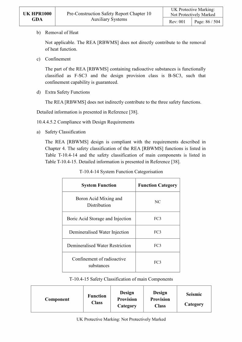
UK HPR1000
GDA
Pre-Construction Safety Report Chapter 10 Auxiliary Systems
UK Protective Marking: Not Protectively Marked
Rev: 001 Page: 86 / 504
UK Protective Marking: Not Protectively Marked
b) Removal of Heat
Not applicable. The REA [RBWMS] does not directly contribute to the removal of heat function.
c) Confinement
The part of the REA [RBWMS] containing radioactive substances is functionally classified as F-SC3 and the design provision class is B-SC3, such that confinement capability is guaranteed.
d) Extra Safety Functions
The REA [RBWMS] does not indirectly contribute to the three safety functions.
Detailed information is presented in Reference [38].
10.4.4.5.2 Compliance with Design Requirements
a) Safety Classification
The REA [RBWMS] design is compliant with the requirements described in Chapter 4. The safety classification of the REA [RBWMS] functions is listed in Table T-10.4-14 and the safety classification of main components is listed in Table T-10.4-15. Detailed information is presented in Reference [38].
T-10.4-14 System Function Categorisation
System Function Function Category
Boron Acid Mixing and Distribution
NC
Boric Acid Storage and Injection FC3
Demineralised Water Injection FC3
Demineralised Water Restriction FC3
Confinement of radioactive substances
FC3
T-10.4-15 Safety Classification of main Components
Component Function
Class
Design
Provision
Category
Design
Provision
Class
Seismic
Category
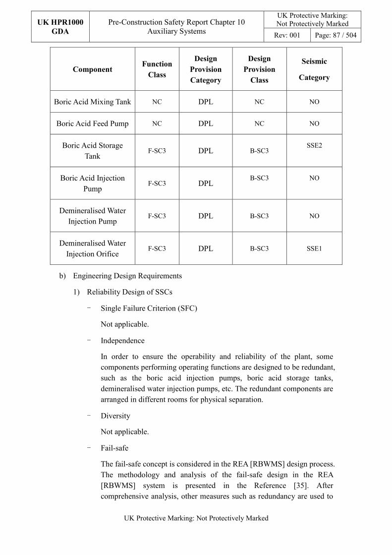
UK HPR1000
GDA
Pre-Construction Safety Report Chapter 10 Auxiliary Systems
UK Protective Marking: Not Protectively Marked
Rev: 001 Page: 87 / 504
UK Protective Marking: Not Protectively Marked
Component Function
Class
Design
Provision
Category
Design
Provision
Class
Seismic
Category
Boric Acid Mixing Tank NC DPL NC NO
Boric Acid Feed Pump NC DPL NC NO
Boric Acid Storage Tank
F-SC3 DPL B-SC3 SSE2
Boric Acid Injection Pump
F-SC3 DPL B-SC3 NO
Demineralised Water Injection Pump
F-SC3 DPL B-SC3 NO
Demineralised Water Injection Orifice
F-SC3 DPL B-SC3 SSE1
b) Engineering Design Requirements
1) Reliability Design of SSCs
- Single Failure Criterion (SFC)
Not applicable.
- Independence
In order to ensure the operability and reliability of the plant, some components performing operating functions are designed to be redundant, such as the boric acid injection pumps, boric acid storage tanks, demineralised water injection pumps, etc. The redundant components are arranged in different rooms for physical separation.
- Diversity
Not applicable.
- Fail-safe
The fail-safe concept is considered in the REA [RBWMS] design process. The methodology and analysis of the fail-safe design in the REA [RBWMS] system is presented in the Reference [35]. After comprehensive analysis, other measures such as redundancy are used to
UK HPR1000
GDA
Pre-Construction Safety Report Chapter 10 Auxiliary Systems
UK Protective Marking: Not Protectively Marked
Rev: 001 Page: 88 / 504
UK Protective Marking: Not Protectively Marked
improve safety in order to avoid the potential safety risks that may be introduced by “fail-safe” design on power plant.
- Ageing and Degradation
The service life of some of the main components of the system is 60 years. For example the boric acid mixing tank, boric acid storage tank, boric acid injection pump, demineralised water injection pump, etc.
The REA [RBWMS] system considers the requirements stated in Sub-chapter 10.2.4, and the design considerations and measures described in Sub-chapter 10.2.4 are applied in the design of the REA [RBWMS].
Detailed design arrangement of EMIT and equipment monitoring is presented in the SDM, Reference [37].
2) Human Factors
The REA [RBWMS] system considers the requirements stated in Sub-chapter 10.2.4, and the design considerations and measures described in Sub-chapter 10.2.4 are applied in the design of the REA [RBWMS].
The system design of the REA [RBWMS] does not require short term operator intervention. In addition, operating modes such as “boration”, “dilution”, “automatic makeup” and “manual makeup” are designed to be operated from the MCR to facilitate operator control of the boron concentration in the primary circuit. Detailed information about automatic control design of the system is presented in the SDM, Reference [37].
3) Autonomy
- Autonomy with respect to Operators
The design principles relevant to the autonomy with respect to operators are detailed in Sub-chapter 10.2.4.The design of the REA [RBWMS] fulfils these principles via control functional design, detailed information is presented in the SDM, Reference [37]. In addition, the demineralised water injection orifice is designed to restrict the flowrate of demineralised water injecting into the primary circuit. Therefore even when the isolation of dilution fails, the system can still guarantee autonomy with respect to operators in 30 minutes.
- Autonomy with respect to the Heat Sink
Not applicable.
- Autonomy with respect to Power Supply Systems
UK HPR1000
GDA
Pre-Construction Safety Report Chapter 10 Auxiliary Systems
UK Protective Marking: Not Protectively Marked
Rev: 001 Page: 89 / 504
UK Protective Marking: Not Protectively Marked
To ensure the operation of the REA [RBWMS] in the event of LOOP, the actuators of the pumps and valves of the boric acid storage and injection sub-system and the demineralised water injection sub-system (REA2~5) are equipped with emergency power supplies.
4) Other Design Requirements
- Prevention of Harmful Interactions of Systems Important to Safety
Provisions have been made to prevent the design pressure of the system operating at the lower pressure from being exceeded. Check valves between the REA [RBWMS] and interfacing systems such as the RIS [SIS] are designed to protect the REA [RBWMS] system from overpressure, Reference [38];
- Considerations Related to the Electrical Power Grid
The design of active components such as the boric acid feed pump, boric acid injection pump and the demineralised water injection pump in the REA [RBWMS] has taken the disturbances in the electrical power grid into consideration. Detailed design information related to the electrical power grid is presented in Reference [38].
c) Equipment Qualification
Equipment qualification applies to mechanical and electrical equipment that perform FC3 functions required to prevent the actuation of the reactor trip and engineering safety systems during deviation from normal operation, including those designed to maintain the main plant parameters with in the normal range of operation of the plant.
All the seismically classified components of the REA [RBWMS] shall be capable of operating during and after the SSE. The demineralised water injection orifice is seismically designed and qualified for SSE loads.
Principles of equipment qualification classification of the system are presented in Reference [38]. Detailed information related to the system equipment qualification is presented in Reference [35].
d) Protection Design against Internal and External Hazards
The REA [RBWMS] system considers the requirements stated in Sub-chapter 10.2.4, the REA [RBWMS] is required to be protected against several external and internal hazards, and the corresponding protection measures are described below:
1) External Hazards
- Earthquake
UK HPR1000
GDA
Pre-Construction Safety Report Chapter 10 Auxiliary Systems
UK Protective Marking: Not Protectively Marked
Rev: 001 Page: 90 / 504
UK Protective Marking: Not Protectively Marked
The seismic class for the demineralised water injection orifice is Seismic Category 1 (SSE1).
Except for the demineralised water injection orifice, the seismic classes for the components performing Safety Category 3 (FC3) safety functions are Seismic Category 2 (SSE2) or NC respectively. The boric acid storage tanks and the components located in Fuel Building (BFX) are Seismic Category 2 (SSE2), and the other components are NC.
- Other external hazards
The REA [RBWMS] protects against external hazards mainly through the building design. Specific protection in the design is presented in Reference [36].
2) Internal Hazards
Precautions are applied during layout design to avoid dropped loads, such as appropriate design and management of hoisting equipment. The specific protection design is presented in Reference [36].
e) Commissioning
Before operation, commissioning and tests are carried out to verify that the performance of the REA [RBWMS] meets the design requirements. The methodology of system commissioning programme design is presented in Reference [31]. The content of the tests includes preparation and distribution of 4% boric acid solution, storage of 4% boric acid solution, and boric acid and demineralised water make-up capability.
Further detailed site specific arrangements for the UK HPR1000 commissioning activities will be presented during the nuclear site licencing phase.
f) Examination, Inspection, Maintenance and Testing
1) Inspections and Surveillance
In-service inspection and pre-service inspection are required for some main components of the REA [RBWMS] such as the boric acid storage tanks and the related relief valves.
The tanks (boric acid mixing tank and boric acid storage tanks) of the REA [RBWMS] are provided with redundant instrumentations to provide surveillance of the equipment. The boric acid mixing tank is equipped with online level measurement as well as remote pressure and temperature measurements for the operators.
All the pump inlets of the REA [RBWMS] system are provided with pressure measurements. The pump motor’s winding stator and the bearing are all
UK HPR1000
GDA
Pre-Construction Safety Report Chapter 10 Auxiliary Systems
UK Protective Marking: Not Protectively Marked
Rev: 001 Page: 91 / 504
UK Protective Marking: Not Protectively Marked
provided with temperature measurements.
The local pressure measurements upstream and downstream of the pumps are used to confirm the operational parameters and operating status of the pumps.
Upstream and downstream of the minimum flow lines heat exchangers (on the hot side), temperature measurement instrumentation monitors the heat transfer of the heat exchangers. The cold side of the heat exchangers is provided with pressure measurement and flow measurement instrumentation used to measure the flow rate of cooling water of the RRI [CCWS]. This instrumentation can indicate the status of the equipment and provide surveillance to avoid equipment failure.
2) Maintenance
The maintenance plans for the REA [RBWMS] are to be determined, where the overall principles in determining the plans are as follows:
- Maintenance of storage tanks must be conducted when the pipelines are out of service.
- For the boric acid and demineralised water makeup pipelines, the maintenance of a piece of equipment can be conducted during unit power operation based on the premise of not affecting the availability of the system.
3) Periodic Tests
Periodic tests are not taken into consideration for the items put into long-term service in the REA [RBWMS]. However, periodic tests shall be taken into consideration for the items not in long-term service (e.g. the isolation valve at the outlet of the boric acid storage tank is in the open position for a long time).
For the UK HPR1000, the periodic test design method is presented in the Reference [32].
g) Decommissioning
The design of the REA [RBWMS] considers the decommissioning. A certain gradient is set in the pipeline layout to prevent liquid accumulation and all equipment and pipes can be drained by draining lines.
h) Material Selection
To avoid corrosion, all the parts of the REA [RBWMS] containing boric acid and reactor coolant are made of austenitic stainless steel, such as pumps, valves, pipes and tanks.
UK HPR1000
GDA
Pre-Construction Safety Report Chapter 10 Auxiliary Systems
UK Protective Marking: Not Protectively Marked
Rev: 001 Page: 92 / 504
UK Protective Marking: Not Protectively Marked
To prevent leakage, all the pipes and equipment of the system have welded connections, except for those which require flanged connections for the purpose of maintenance and inspection.
i) Special Thermal-hydraulic Phenomena
In order to ensure the functional reliability of the system and to prevent challenges in performing its safety functions, the hydraulic phenomenon listed below are considered in the REA [RBWMS] design:
1) Phenomenon regarding the water hammer
Before the system is put into operation, it is filled with fluid and sufficiently vented to avoid the phenomenon of water hammer in the process of system start-up or shut down.
j) Insulation
The pipes and components containing fluid with a temperature more than 60°C require insulation design to protect the workers, including the boric acid mixing tank and its connected pipes, and the pipes from the TEP [CSTS] to the boric acid storage tanks.
10.4.4.6 Simplified Diagram
The simplified system functional diagram is presented in Figure F-10.4-2. Detailed system functional diagram is in Reference [39].
10.4.5 Coolant Storage and Treatment System (TEP [CSTS])
The TEP [CSTS] performs the functions of receiving, separating and degassing reusable primary coolant. The TEP [CSTS] consists of coolant storage tanks, the evaporation unit, the condensate degasification unit and the coolant degasification unit. The main components of the TEP [CSTS] are located in the nuclear auxiliary building. Systeminformation is presented in the SDM, Reference [40].
10.4.5.1 Safety Functional Requirements
10.4.5.1.1 Control of Reactivity
The TEP [CSTS] does not contribute to the safety function of control of reactivity.
10.4.5.1.2 Removal of Heat
The TEP [CSTS] does not contribute to the safety function of removal of heat.
10.4.5.1.3 Confinement
The TEP [CSTS] contributes to achieve confinement of radioactive waste in normal operation.
UK HPR1000
GDA
Pre-Construction Safety Report Chapter 10 Auxiliary Systems
UK Protective Marking: Not Protectively Marked
Rev: 001 Page: 93 / 504
UK Protective Marking: Not Protectively Marked
10.4.5.1.4 Extra Safety Functions
The TEP [CSTS] does not indirectly contribute to the three safety functions.
10.4.5.2 Design Requirements
In this sub-chapter, the applicability of design requirements listed in Sub-chapter 10.2.4 are analysed for the TEP [CSTS].
The design requirements not applicable in the design of the TEP [CSTS] are as follows:
a) Reliability Design of SSCs
1) Single Failure Criterion (SFC)
Not applicable, since the TEP [CSTS] does not perform any FC1-level safety functions, the SFC does not apply to this system.
2) Diversity
Not applicable. There is no diversity design in the TEP [CSTS].
b) Autonomy in Respect of the Heat Sink
Not applicable, because the TEP [CSTS] doesn’t provide a heat sink to the power plant.
The substantiation analysis of the TEP [CSTS] to other design requirements is shown in 10.4.5.5.
10.4.5.3 Design Bases
This sub-chapter presents the main design assumptions considered in the system design.
10.4.5.3.1 General Assumptions
a) Safety Classification
The confinement of radioactive substances function of the TEP [CSTS] is required to prevent radioactivity release in all conditions, the function category is FC3.
b) Ageing and Degradation
The main components of the TEP [CSTS] are required to have a service life of 60 years.
c) Considerations Related to the Electrical Power Grid
The functionality of items important to safety at the nuclear power plant shall not be compromised by disturbances in the electrical power grid, including
UK HPR1000
GDA
Pre-Construction Safety Report Chapter 10 Auxiliary Systems
UK Protective Marking: Not Protectively Marked
Rev: 001 Page: 94 / 504
UK Protective Marking: Not Protectively Marked
anticipated variations in the voltage and frequency of the grid supply.
10.4.5.3.2 Design Assumptions
a) Control of Reactivity
Not applicable. The TEP [CSTS] does not contribute to the function of control of reactivity.
b) Removal of Heat
Not applicable. The TEP [CSTS] does not contribute to the safety function of removal of heat.
c) Confinement
Not applicable. There’s no quantitative safety-related design assumption for the TEP [CSTS].
d) Extra Safety Functions
Not applicable. There’s no quantitative safety-related design assumption for TEP [CSTS].
10.4.5.4 System Description and Operation
10.4.5.4.1 System Description
a) General System Description
The TEP [CSTS] is divided into the following sub-systems:
1) Coolant Storage and Supply Sub-system (TEP [CSTS] 1)
The coolant storage and supply sub-system is mainly comprised of the following components:
- Six coolant storage tanks;
- One borated water pipeline;
- One demineralised water pipeline.
Each coolant storage tank is connected to the borated water pipeline and demineralised water pipeline through an isolation valve.
The tanks are constantly swept with nitrogen taken from the TEG [GWTS] to prevent accumulation of flammable gas mixtures in the system free spaces. Additionally, the tanks are operated below atmospheric pressure to prevent hydrogen leakage from the system.
Detailed information is presented in the SDM, Reference [41].
UK HPR1000
GDA
Pre-Construction Safety Report Chapter 10 Auxiliary Systems
UK Protective Marking: Not Protectively Marked
Rev: 001 Page: 95 / 504
UK Protective Marking: Not Protectively Marked
2) Coolant Purification Sub-system (TEP [CSTS] 2)
The coolant purification sub-system consists of:
- Two makeup pumps of the boric acid distillation tower;
- One mixed bed demineraliser;
- One cartridge filter (resin trapper).
The mixed bed demineraliser and downstream resin trapper are installed between the coolant storage and supply sub-system (TEP [CSTS] 1) and coolant treatment sub-system (TEP [CSTS] 3, 5 and 6).
3) Coolant Treatment Sub-system (TEP [CSTS] 3, 5 and 6)
The coolant treatment sub-system consists of:
- One evaporation unit;
- One condensate degasification unit.
The coolant treatment sub-system separates reactor coolant into demineralised water and boric acid solution. Redundancy is considered for all important active components to improve system availability.
4) Coolant Degasification Sub-system (TEP [CSTS] 4)
The coolant degasification sub-system mainly consists of:
- One coolant degasification unit.
The degasification vacuum pump will depressurise the coolant when its temperature reaches the boiling point of 50°C. Meanwhile, the vacuum pump is used to extract gases originating out of the degasification tower.
Detailed information is presented in the SDM, Reference [41].
a) Description of Main Equipment
The main equipment is described as follows:
1) Coolant Storage Tanks
Coolant storage tanks are vertical cylindrical vessels which receive reusable primary coolant or demineralised water (distillate) from the coolant treatment sub-system.
2) Evaporator
The evaporator in the evaporation unit is a packed column separating reusable primary coolant into demineralised water and 7000mg/kg boric acid solution, which is returned to the REA [RBWMS] for reuse.
UK HPR1000
GDA
Pre-Construction Safety Report Chapter 10 Auxiliary Systems
UK Protective Marking: Not Protectively Marked
Rev: 001 Page: 96 / 504
UK Protective Marking: Not Protectively Marked
3) Degasification Columns
The degasification columns of the coolant and condensate degasification units are packed columns degasifying the liquid to be treated, so as to reduce its radioactivity.
4) Mixed Bed Demineraliser
The mixed bed demineraliser in the coolant purification sub-system is a cylindrical pressure vessel with hemispherical heads. It is filled with anion and cation resins to remove ionic and solvent impurities from the coolant.
5) Pumps and Compressors
The TEP [CSTS] is equipped with multiple centrifugal pumps to provide the drive required for fluid flowing in the system.
The vapour compressor is a rotary compressor with a sufficient compression ratio to produce enough heat to maintain sufficient evaporation in the evaporator.
The vacuum pump is a liquid ring vacuum pump which provides the coolant degasification column with the required operation pressure (negative pressure), so that the coolant will evaporate at a temperature near the letdown temperature.
6) Heat Exchangers
The TEP [CSTS] is equipped with multiple heat exchangers to recover system heat and cool fluid. The heat exchangers are of tube-shell type.
Detailed information is presented in the SDM, Reference [41].
b) Description of Main Layout
The TEP [CSTS] is located in the BNX.
Detailed information is presented in the SDM, Reference [42].
c) Description of System Interfaces
1) Operational Chilled Water System DER [OCWS]
The DER [OCWS] supplies the sealing liquid cooler of the degasifier vacuum pump with chilled water.
2) Nuclear Auxiliary Building Ventilation System (DWN [NABVS])
The DWN [NABVS] is used when the tank atmosphere has to be flushed with air. In case the activity released by the TEP [CSTS] 4 does not result in a high activity in the stack, the extracted gases can be exhausted towards the

UK HPR1000
GDA
Pre-Construction Safety Report Chapter 10 Auxiliary Systems
UK Protective Marking: Not Protectively Marked
Rev: 001 Page: 97 / 504
UK Protective Marking: Not Protectively Marked
DWN [NABVS].
3) NI Demineralised Water Distribution System (SED [DWDS (NI)])
The SED [DWDS (NI)] flushes the equipment and provides demineralised water to replenish it.
4) Nuclear Island Vent and Drain System (RPE [VDS])
The RPE [VDS] provides a number of vents and drains for the TEP [CSTS].
The borated water line of the coolant storage and supply sub-system accepts reactor coolant effluents from the RPE [VDS].
5) Nuclear Sampling System (REN [NSS])
The REN [NSS] determines the decontamination factor or chemical composition of the reactor coolant and sweeping gas.
6) Component Cooling Water System (RRI [CCWS])
The RRI [CCWS] supplies the condenser, gas cooler and several heat exchangers with component cooling water.
7) Service Compressed Air Distribution System (SAT [SCADS])
The SAT [SCADS] provides compressed air during the outage of the TEP [CSTS] tanks and columns.
8) Nitrogen Distribution System (SGN [NDS])
The SGN [NDS] can supply nitrogen to the TEP [CSTS] 4 and serve the TEP [CSTS] in coolant storage tank outage.
9) Gaseous Waste Treatment System (TEG [GWTS])
The TEG [GWTS] supplies nitrogen for flushing purposes as well as exhausting extracted gases.
10) Solid Waste Treatment System (TES [SWTS])
The spent resins are transported out of the mixed bed filter of the TEP [CSTS] 2 to the resin waste tanks by the TES [SWTS].
11) Nuclear Island Liquid Waste Discharge System (TER [NLWDS])
Condensate can be discharged to the TER [NLWDS] for tritium balancing after treatment (evaporation and subsequent degasification).
12) Reactor Boron and Water Makeup System (REA [RBWMS])
The demineralised water stored in one coolant storage tank is delivered to the REA [RBWMS]. Boric acid collected in the evaporation unit is sent to the
UK HPR1000
GDA
Pre-Construction Safety Report Chapter 10 Auxiliary Systems
UK Protective Marking: Not Protectively Marked
Rev: 001 Page: 98 / 504
UK Protective Marking: Not Protectively Marked
REA [RBWMS]. The make-up water electrical preheater is used for the supply of heated demineralised water to the REA [RBWMS].
13) Chemical and Volume Control System (RCV [CVCS])
The borated water line of the coolant storage and supply sub-system accepts coolant from the RCV [CVCS]. The coolant coming from the RCV [CVCS] enters the coolant degasification system for degassing. The degassed coolant is transferred back to the RCV [CVCS].
Detailed information is presented in the SDM, Reference [41].
d) Description of Instrumentation and Control
The TEP [CSTS] is a fully automated system. Therefore it is provided with a set of group commands, controllers and instrumentations. The normal operation of the TEP system is automatic. However, the operator also has the ability to operate the system manually.
Detailed information is presented in the SDM, Reference [43].
10.4.5.4.2 System Operation
a) Plant Normal Conditions
1) Coolant Storage and Supply Sub-system (TEP [CSTS] 1)
During normal operation of the NPP, one coolant storage tank is permanently connected to the coolant header and the other coolant storage tanks are permanently connected to the demineralised water header. Coolant or demineralised water can be received and delivered at the same time.
2) Coolant Purification Sub-system (TEP [CSTS] 2)
TEP [CSTS] 2 transfers coolant from TEP [CSTS] 1 to TEP [CSTS] 3, 5 and 6. The coolant is demineralised and filtered by the demineraliser of TEP [CSTS] 2. The mixed bed demineraliser is filled with H+ and OH- ions, to remove residual lithium and caesium, while other isotope ions will not be removed by the demineraliser of the RCV [CVCS].
3) Coolant Treatment Sub-system (TEP [CSTS] 3, 5 and 6)
TEP [CSTS] 3, 5 and 6 operate in four modes:
- Distillation Separation without Degasification and Reuse after Treatment
Coolant is pumped to the boric acid column by its makeup pump after a two-stage regenerative heat exchange (the heat of boric acid and distillate from the boric acid column are recovered). When the coolant is heated to boiling, the vapour generated is extracted by two vapour
UK HPR1000
GDA
Pre-Construction Safety Report Chapter 10 Auxiliary Systems
UK Protective Marking: Not Protectively Marked
Rev: 001 Page: 99 / 504
UK Protective Marking: Not Protectively Marked
compressors and delivered to the heat exchanger shell side of the boric acid column. Condensate is collected in the condensate container and tank, and its vapour and water are separated. The condensate is cooled to 50°C and pumped by the condensate transfer pump to the coolant storage tanks of TEP [CSTS] 1 for reuse.
- Distillation Separation with Degasification and Reuse after Treatment
Operations of this mode are the same as those of the mode outlined above except that the condensate flows into TEP [CSTS] 6 through a bypass before entering the regenerative preheater. It is degasified and cooled to 50°C by the regenerative preheater and subsequent cooler, and then transferred to the coolant storage tanks of TEP [CSTS] 1 for reuse.
- Distillation Separation with Degasification and Condensate Discharge after Treatment
The treated condensate will be subject to the operations in the mode described above and then transferred to the TER [NLWDS] directly instead of TEP [CSTS] 1 for discharge. This occurs when the quality of the condensate cannot meet the required standard or be reused, such as when the tritium content in the primary loop is higher than the standard amount and needs to be discharged.
- Degasification of Makeup Water
Demineralised water makeup is required when the condensate is partially discharged. The makeup water is supplied by the SED [DWDS (NI)], heated by the makeup water preheater, piped to TEP [CSTS] 6, degasified, cooled to 50°C, and transferred to the coolant storage tanks of TEP [CSTS] 1 for storage and reuse.
4) Coolant Degasification Sub-system (TEP [CSTS] 4)
Coolant is piped from the RCV [CVCS] to the coolant degasification sub-system (TEP [CSTS] 4). Degasified coolant is returned to the RCV [CVCS]. Gases removed from the primary coolant are transferred to the TEG [GWTS] or the DWN [NABVS].
Reactor coolant at about 50°C is piped from the RCV [CVCS] to the top of the coolant degasification tower. It flows in the opposite direction to the rising vapour, and the non-condensable gases dissolved in it are removed.
b) Plant Accident Conditions
There is no demand for the TEP [CSTS] to operate in plant accident conditions.
UK HPR1000
GDA
Pre-Construction Safety Report Chapter 10 Auxiliary Systems
UK Protective Marking: Not Protectively Marked
Rev: 001 Page: 100 /
504
UK Protective Marking: Not Protectively Marked
10.4.5.5 Preliminary Design Substantiation
In this sub-chapter, the system design is demonstrated to satisfy the Safety Functional Requirements presented in Sub-chapter 10.4.5.1 and the general design requirements stated in Sub-chapter 10.2.4. Review of consistency of the system design with the newly developed principles is currently being undertaken.
10.4.5.5.1 Compliance with Safety Functional Requirements
a) Control of Reactivity
The TEP [CSTS] does not contribute to this function.
b) Removal of Heat
The TEP [CSTS] does not contribute to this function.
c) Confinement
The confinement of radioactive material is ensured by the sealing of the mechanical boundaries. Moreover, the TEP [CSTS] is located within the BNX building and the civil engineering structure acts as a barrier to the environment.
d) Extra Safety Functions
The TEP [CSTS] does not contribute to this function.
10.4.5.5.2 Compliance with Design Requirements
a) Safety Classification
The safety categorisation of the TEP [CSTS] is listed in Table T-10.4-16 and the main components in Table T-10.4-17. Detailed information is presented in Reference [44].
T-10.4-16 Function Categorisation of the TEP [CSTS]
System Function Function Categorisation
Coolant Supply and Storage Sub-system FC3
Coolant Purification Sub-system FC3
Coolant Treatment Sub-system (Except seal water circuit for vapour compressors)
FC3
Coolant Treatment Sub-system (seal water circuit for vapour compressors)
NC
UK HPR1000
GDA
Pre-Construction Safety Report Chapter 10 Auxiliary Systems
UK Protective Marking: Not Protectively Marked
Rev: 001 Page: 101 /
504
UK Protective Marking: Not Protectively Marked
System Function Function Categorisation
Collection of condensates degasification FC3
Coolant Degasification Sub-system FC3
T-10.4-17 Classification for Components
Component Function
Class
Design
Provision
Category
Design
Provision
Class
Seismic
Category
Coolant Storage Tanks F-SC3 DPL B-SC3 NO
Evaporator F-SC3 DPL B-SC3 NO
Boric Acid Column F-SC3 DPL B-SC3 NO
Degasifier Column (TEP [CSTS] 4) F-SC3 DPL B-SC3 NO
Degasifier Column (TEP [CSTS] 6) F-SC3 DPL B-SC3 NO
Mixed Bed Demineraliser F-SC3 DPL B-SC3 NO
Compressors F-SC3 DPL B-SC3 NO
b) Engineering Design Requirements
1) Reliability Design of SSCs
- Single Failure Criterion (SFC)
Not applicable.
- Independence
In order to ensure the operability and reliability of the plant, some components performing operational functions are designed to be redundant, such as the boric acid column feed pumps and circulation pumps, etc. The redundant components are arranged in different rooms for physical separation.
- Diversity
Not applicable.
UK HPR1000
GDA
Pre-Construction Safety Report Chapter 10 Auxiliary Systems
UK Protective Marking: Not Protectively Marked
Rev: 001 Page: 102 /
504
UK Protective Marking: Not Protectively Marked
- Fail-safe
The fail-safe concept is considered in the TEP [CSTS] design process. The methodology and analysis of the fail-safe design in the TEP [CSTS] system is presented in the Reference [41]. After comprehensive analysis, the means of “fail-safe” design does not meet the specific safety consideration, therefore measures other than the fail-safe design such as redundancy are used to improve safety of power plant in order to avoid the potential safety risks that may be introduced by “fail-safe” design on power plant.
- Ageing and Degradation
The service life of some of the main components of the system is also 60 years.
The design considerations and measures described in Sub-chapter 10.2.4 are applied in the design of the TEP [CSTS].
Detailed design arrangement around EMIT and equipment monitoring is presented in the SDM, Reference [43].
2) Human Factors
The design considerations and measures described in Sub-chapter 10.2.4 are applied in the design of the TEP [CSTS].
The TEP [CSTS] does not require short term operator intervention. Detailed information about automatic control design of the system is presented in the SDM, Reference [43].
3) Autonomy
- Autonomy in Respect of Operators
The design principles relevant to the autonomy in respect of operators are detailed in Sub-chapter 10.2.4. The design of the TEP [CSTS] fulfils these principles via control functional design; detailed information is presented in the SDM, Reference [43].
- Autonomy in Respect of the Heat Sink
Not applicable.
- Autonomy in Respect of Power Supply Systems
To ensure the operation of the TEP [CSTS] in case of LOOP, the actuators of valves of the coolant supply and storage sub-system are equipped with emergency power supplies.
UK HPR1000
GDA
Pre-Construction Safety Report Chapter 10 Auxiliary Systems
UK Protective Marking: Not Protectively Marked
Rev: 001 Page: 103 /
504
UK Protective Marking: Not Protectively Marked
4) Other Design Requirements
- Prevention of Harmful Interactions of Systems Important to Safety
Provisions have been made to prevent radioactivity from being released to supporting systems. Radioactivity detecting instruments are designed on the shell side of the heat exchanger of the TEP [CSTS]. When a leak is detected, the heat exchanger can be isolated to prevent radioactivity release to the RRI [CCWS].
- Considerations Related to the Electrical Power Grid
The design of active components such as the sample backfeed pumps in the TEP [CSTS] has taken the disturbances in the electrical power grid into consideration. Detailed design information of the electrical power grid is presented in the Reference [44].
c) Equipment Qualification
Not applicable.
d) Protection Design against Internal and External Hazards
The TEP [CSTS] considers with the requirements stated in Sub-chapter 10.2.4, and the design considerations and measures described in Sub-chapter 10.2.4 are applied in the design of the TEP [CSTS]. The TEP [CSTS] has no specific provisions with regard to internal and external hazards.
1) External Hazards
- Earthquake
According to the safety function class and the design provision category of the TEP [CSTS], the seismic category of the TEP [CSTS] is NO.
- Other external hazards
The TEP [CSTS] is protected against external disasters mainly through the building design. Specific protection design is presented in Reference [42].
2) Internal Hazards
Precautions are applied during layout design to avoid dropped loads, such as appropriate design and management of hoisting equipment. The specific protection design is presented in Reference [42].
e) Commissioning
The TEP [CSTS] will be subject to commissioning tests before putting it into operation, to verify that its component performance meets the requirements.
UK HPR1000
GDA
Pre-Construction Safety Report Chapter 10 Auxiliary Systems
UK Protective Marking: Not Protectively Marked
Rev: 001 Page: 104 /
504
UK Protective Marking: Not Protectively Marked
Further detailed site specific arrangements for the UK HPR1000 commissioning activities will be presented during the nuclear site licencing phase in conjunction with the site licensee.
f) Examination, Inspection, Maintenance and Testing
1) Inspections and Surveillances
In-service inspections are implemented for the equipment of the TEP [CSTS], including the coolant storage tanks and columns.
2) Maintenance
Some components will need to be replaced at the end of their individual designed life. The layout design will take into consideration the need to remove old parts and the installation of replacements.
3) Periodic Tests
Periodic tests are not required for the TEP [CSTS].
g) Decommissioning
The design of the TEP [CSTS] considers the decommissioning. A certain gradient is set in the pipeline layout to prevent liquid accumulation and all equipment and pipes can be drained by draining lines.
h) Material Selection
To avoid corrosion, all the parts of the TEP [CSTS] containing boric acid and reactor coolant are made of austenitic stainless steel, such as the pumps, valves, pipes and tanks.
i) Special Thermal-hydraulic Phenomena
In order to ensure the functional reliability of the system and to prevent challenges in performing the safety functions, the hydraulic phenomena listed below are carefully considered in TEP [CSTS] design:
1) Phenomenon regarding the dead leg;
2) Phenomenon regarding the hot water and cold water mixing;
3) Phenomenon regarding the thermal stratification;
4) Phenomenon regarding the water hammer.
j) Insulation
The pipes and components containing fluid with a temperature greater than 60 °C require insulation to protect workers.
UK HPR1000
GDA
Pre-Construction Safety Report Chapter 10 Auxiliary Systems
UK Protective Marking: Not Protectively Marked
Rev: 001 Page: 105 /
504
UK Protective Marking: Not Protectively Marked
10.4.5.6 Simplified Diagrams
The simplified system diagram is presented in Figure F-10.4-3. Detailed system functional diagram is in Reference [45].
10.4.6 Nuclear Sampling System (REN [NSS])
REN [NSS] mainly enables centralised analysis and determination of the chemical and radio-chemical characteristics of samples taken from the RCP [RCS], secondary side of the SGs, nuclear auxiliary systems and liquid waste and gaseous waste treatment system. The REN [NSS] comprises three sub-systems: the primary sampling system, secondary sampling system and post-accident sampling system. The main components of the REN [NSS] (sampling coolers, pumps, tanks, glove boxes and analysers) are located in the BFX) and BNX of the Nuclear Island (NI). Information of the system is presented in the SDM, Reference [46].
10.4.6.1 Safety Functional Requirements
10.4.6.1.1 Control of Reactivity
The REN [NSS] contributes to the control of reactivity by isolating the high temperature sampling cooler to prevent dilution accidents in DBC-4 conditions.
10.4.6.1.2 Removal of Heat
The REN [NSS] does not directly contribute to this safety function.
10.4.6.1.3 Confinement
The REN [NSS] contributes to the confinement of radioactive substances:
a) Containment isolation: Sample lines penetrating the containment shall be isolated to prevent the leakage of radioactive fluid in accident conditions (as the third containment barrier);
b) RCPB isolation: Isolation valves in the three primary sampling lines connected to the reactor coolant system shall be isolated in the event of a line failure outside the containment to maintain RCPB integrity (as the third containment barrier);
c) SG sampling lines isolation: The SG sampling lines shall be isolated in the event of SGTR to confine activity in the failed SG (as the second containment barrier);
d) Confinement of radioactive substances: The REN [NSS] primary sampling lines shall confine the radioactive substances when transporting radioactive substances in normal operating conditions. The secondary sampling lines shall confine the radioactive substances when the primary fluid leaks into the secondary circuit.
UK HPR1000
GDA
Pre-Construction Safety Report Chapter 10 Auxiliary Systems
UK Protective Marking: Not Protectively Marked
Rev: 001 Page: 106 /
504
UK Protective Marking: Not Protectively Marked
10.4.6.1.4 Extra Safety Functions
a) The REN [NSS] shall provide boron concentration monitoring of the primary coolant to support the control of reactivity.
b) The REN [NSS] shall provide samples for activity monitoring to support the confinement of radioactive substances:
1) The REN [NSS] shall provide appropriate liquid samples for evaluation of the primary coolant activity to detect the integrity of the fuel cladding;
2) The REN [NSS] shall provide appropriate liquid samples for evaluation of the secondary fluid activity to detect the integrity of the SGs;
3) The REN [NSS] shall provide appropriate liquid samples from the IRWST after accidents to evaluate the effect of accidents on the environment;
4) The REN [NSS] shall provide appropriate gaseous samples inside the containment after accidents to evaluate the effect of accidents on the environment.
10.4.6.2 Design Requirements
The general design requirements of the nuclear auxiliary systems which need to be considered are shown in Sub-chapter 10.2.4, among which the following requirements are not applicable for the REN [NSS]:
a) Autonomy with respect to the Heat Sink
Not applicable, because the REN [NSS] doesn’t provide a heat sink to the power plant.
The substantiation analysis of the REN [NSS] to other design requirements is shown in the Sub-chapter 10.4.6.5.
10.4.6.3 Design Bases
This sub-chapter presents the main design assumptions considered in the system design.
10.4.6.3.1 General Assumptions
a) Safety Classification
The RCPB isolation function is required to confine the radioactive substances in DBC-3/4 conditions, the function category is FC2.
The containment isolation function is required to confine the radioactive substances after a design basis accident, the function category is FC1.
The high temperature sampling cooler isolation function is required to prevent
UK HPR1000
GDA
Pre-Construction Safety Report Chapter 10 Auxiliary Systems
UK Protective Marking: Not Protectively Marked
Rev: 001 Page: 107 /
504
UK Protective Marking: Not Protectively Marked
dilution accident in DBC-4 conditions, the function category is FC2.
The primary sampling function is required to provide boron concentration monitoring of the primary coolant, the function category is FC3.
The SG secondary side sampling (to the Plant Radiation Monitoring System (KRT [PRMS])) function is required to detect the leakage of the SG tubes, the function category is FC2.
The SG sampling isolation function is required to confine activity in the failed SG in a SGTR accident, the function category is FC2.
The confinement of radioactive substances function is required to prevent release of radioactivity in normal operating conditions, the function category is FC3.
The post-accident IRWST sampling function is required to provide information of the effects of the accident on the environment in accident conditions, the function category is FC3.
The post-accident sampling of the containment gaseous phase function is required to provide information of the effects of the accident on the environment in accident conditions, the function category is FC3.
b) Ageing and Degradation
According to Chapter 2, the operational design life of the UK HPR1000 is 60 years. The main components of the REN [NSS] are required to have a service life of 60 years.
Ageing effects must be considered in the design of components such as the heat exchangers. A sufficient margin must be taken into account for the sizing of the high temperature heat exchangers of the REN [NSS].
c) Considerations Related to the Electrical Power Grid
The functionality of items important to safety at the nuclear power plant shall not be compromised by disturbances in the electrical power grid, including anticipated variations in the voltage and frequency of the grid supply.
10.4.6.3.2 Design Assumptions
This sub-chapter presents the main design assumptions considered in the system design.
a) Control of Reactivity
Not applicable. The REN [NSS] system does not directly contribute to the safety function of control of reactivity.
b) Removal of Heat
UK HPR1000
GDA
Pre-Construction Safety Report Chapter 10 Auxiliary Systems
UK Protective Marking: Not Protectively Marked
Rev: 001 Page: 108 /
504
UK Protective Marking: Not Protectively Marked
Not applicable. The REN system does not directly contribute to the safety function of removal of heat.
c) Confinement
There’s no quantitative safety-related design assumption.
d) Extra Safety Functions
Not applicable. There’s no quantitative safety-related design assumption for the REN [NSS].
10.4.6.4 System Description and Operation
10.4.6.4.1 System Description
a) General System Description
1) Primary Sampling System
The primary sampling system collects liquid and gaseous samples from the primary coolant system, the primary auxiliary systems and the liquid and gaseous waste treatment systems to determine the physical and chemical characteristics of these samples by measurements and analysis. These samples are categorised as active liquid, slightly active liquid or gaseous ones.
The primary sampling lines are equipped with a boron meter, a hydrogen meter, an oxygen meter and a phase separator. Each of the analysers mentioned above is connected to the sampling lines of the RCP [RCS], RIS [SIS] and RCV [CVCS]. Gaseous samples are collected via degassers from nozzles.
The backfeed tank recycles the primary samples for the RCV [CVCS] or transfers them to the RPE [VDS].
The sampling line upstream of the backfeed tank is equipped with an activity measurement device which belongs to the KRT [PRMS].
2) Secondary Sampling System
The secondary sampling system collects liquid samples from the SGs in the Steam Generator Blowdown System (APG [SGBS]) and collects liquid samples from the APG [SGBS] purification unit to analyse the blowdown quality and radioactivity.
Each sampling line of the APG [SGBS] is equipped with a pH meter, a conductivity meter and an activity measurement device which belongs to the KRT [PRMS]. A sodium meter is connected to the three SG sampling lines.
UK HPR1000
GDA
Pre-Construction Safety Report Chapter 10 Auxiliary Systems
UK Protective Marking: Not Protectively Marked
Rev: 001 Page: 109 /
504
UK Protective Marking: Not Protectively Marked
Each sampling line of the APG [SGBS] purification is equipped with a conductivity meter. A sodium meter is connected to the two APG [SGBS] anion demineralization beds sampling lines.
There is a backfeed tank which recycles the secondary samples to the APG [SGBS] or transfers them to the RPE [VDS].
3) Post-Accident Sampling System
The post-accident sampling system is used to obtain gaseous and liquid samples in the containment after accidents. The sampling points are as follows:
- Containment atmosphere;
- IRWST, through the EHR [CHRS].
The post-accident sampling system is mainly composed of the following parts:
- Containment isolation valves;
- Two trains of containment atmosphere sampling lines;
- Two trains of EHR [CHRS] sampling lines;
- Sample return lines;
- Sample processing module;
- Local control cabinet.
Detailed information of the systems is presented in the SDM, Reference [47].
b) Description of Main Equipment
1) High Temperature Heat Exchangers
The primary and secondary heat exchangers are designed to cool down the samples of the RCP [RCS] and SGs.
2) Sample Coolers
The sample coolers are designed to provide the constant inlet temperatures required by the on-line analysers and grab sampling.
3) Backfeed Pumps
The sample backfeed pumps are designed to recycle the samples from the backfeed vessel to the RCV [CVCS] (for primary samples) or APG [SGBS] (for secondary samples).
4) Sampling Glove Boxes

UK HPR1000
GDA
Pre-Construction Safety Report Chapter 10 Auxiliary Systems
UK Protective Marking: Not Protectively Marked
Rev: 001 Page: 110 /
504
UK Protective Marking: Not Protectively Marked
Sampling glove boxes are provided with the gloves and a hatch. Both the inlet and outlet of glove boxes are provided with filters. All the glove boxes are equipped with fans and are connected to the DWN [NABVS] to evacuate the air in the glove box to the venting system and ensure a negative pressure to prevent gas from leaking to the laboratory atmosphere. Design parameters are shown in the Table T-10.4-18, and detailed information is presented in the SDM, Reference [47].
T-10.4-18 Parameters of sampling glove boxes
Parameter Technical Data
Design pressure 0.0025MPa g
Design temperature 50°C
Material Stainless steel
Component classification
NC
5) Online Analysers
The parameters of primary and secondary samples are monitored continuously by on-line analysers. The REN [NSS] contains the following on-line analysers: a boron meter, a hydrogen meter, an oxygen meter, two sodium meters, three pH meters and seven conductivity meters.
Detailed information of the equipment design is presented in the SDM, Reference [47].
b) Description of Main Layout
Most of the REN [NSS] is located in the BNX except for the high temperature heat exchangers and high pressure reducing valves in the BFX.
Detailed design information about the system layout is presented in the SDM, Reference [48].
c) Description of System Interfaces
1) RRI [CCWS]
The RRI [CCWS] supplies cooling water to primary and secondary sample high temperature heat exchangers.
2) Operational Chilled Water System (DER [OCWS])
The DER [OCWS] supplies chilled water to the sample coolers to cool down the sample streams upstream of the on-line analysers and for grab sampling.
UK HPR1000
GDA
Pre-Construction Safety Report Chapter 10 Auxiliary Systems
UK Protective Marking: Not Protectively Marked
Rev: 001 Page: 111 /
504
UK Protective Marking: Not Protectively Marked
3) KRT [PRMS]
This system provides on-line monitoring for the activity of primary and secondary samples.
Detailed information of the interfacing systems is presented in the SDM, Reference [47].
d) Description of Instrumentation and Control
During normal plant operation, continuous monitoring of the primary coolant and SG blowdown water is performed by online analysers. These sample lines are automatically isolated at the containment isolation signal.
Detailed information of the system I&C design is presented in the SDM, Reference [49].
10.4.6.4.2 System Operation
a) Plant Normal Conditions
1) Primary Sampling Lines
During normal operation, the sampling lines of the primary coolant operate continuously and the samples are transported to the online analysers in the BNX. Furthermore, liquid and gaseous grab samples can be taken intermittently and sent to the laboratory for further analysis.
During plant shutdown and reactor refuelling conditions while in RHR mode, samples are taken from the RIS [SIS].
The content of the tank is recycled continuously.
2) Secondary Sampling Lines
During normal operation, the sampling lines of the SG blowdown and the APG [SGBS] purification operate continuously and the samples are transported to the online analysers in the BNX. Furthermore, grab samples can be taken intermittently and sent to the laboratory for further analysis.
The sampling lines of nozzles on the SG feedwater are isolated.
3) Post-Accident Sampling System
The post-accident sampling system is not used during normal conditions. All the valves of the system are closed and pipe tracing is shut off. The NI Dematerialised Water Distribution System (SED [DWDS (NI)]) is on standby.
b) Plant Accident Conditions
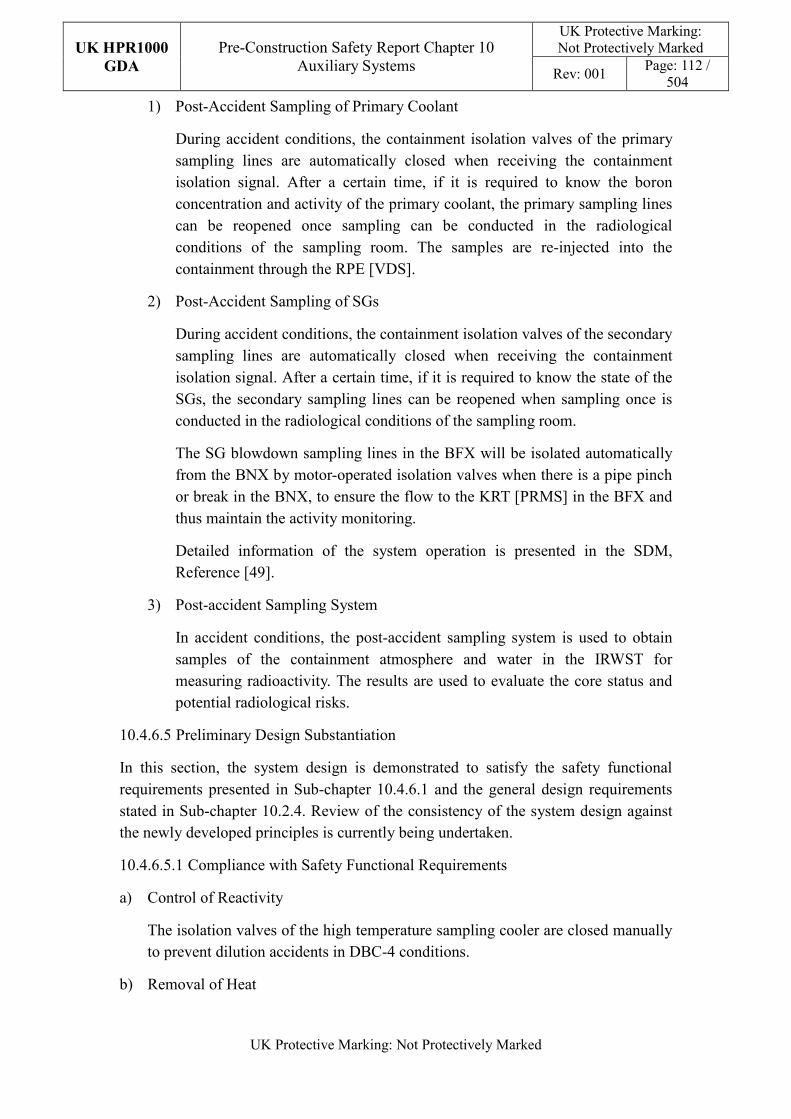
UK HPR1000
GDA
Pre-Construction Safety Report Chapter 10 Auxiliary Systems
UK Protective Marking: Not Protectively Marked
Rev: 001 Page: 112 /
504
UK Protective Marking: Not Protectively Marked
1) Post-Accident Sampling of Primary Coolant
During accident conditions, the containment isolation valves of the primary sampling lines are automatically closed when receiving the containment isolation signal. After a certain time, if it is required to know the boron concentration and activity of the primary coolant, the primary sampling lines can be reopened once sampling can be conducted in the radiological conditions of the sampling room. The samples are re-injected into the containment through the RPE [VDS].
2) Post-Accident Sampling of SGs
During accident conditions, the containment isolation valves of the secondary sampling lines are automatically closed when receiving the containment isolation signal. After a certain time, if it is required to know the state of the SGs, the secondary sampling lines can be reopened when sampling once is conducted in the radiological conditions of the sampling room.
The SG blowdown sampling lines in the BFX will be isolated automatically from the BNX by motor-operated isolation valves when there is a pipe pinch or break in the BNX, to ensure the flow to the KRT [PRMS] in the BFX and thus maintain the activity monitoring.
Detailed information of the system operation is presented in the SDM, Reference [49].
3) Post-accident Sampling System
In accident conditions, the post-accident sampling system is used to obtain samples of the containment atmosphere and water in the IRWST for measuring radioactivity. The results are used to evaluate the core status and potential radiological risks.
10.4.6.5 Preliminary Design Substantiation
In this section, the system design is demonstrated to satisfy the safety functional requirements presented in Sub-chapter 10.4.6.1 and the general design requirements stated in Sub-chapter 10.2.4. Review of the consistency of the system design against the newly developed principles is currently being undertaken.
10.4.6.5.1 Compliance with Safety Functional Requirements
a) Control of Reactivity
The isolation valves of the high temperature sampling cooler are closed manually to prevent dilution accidents in DBC-4 conditions.
b) Removal of Heat
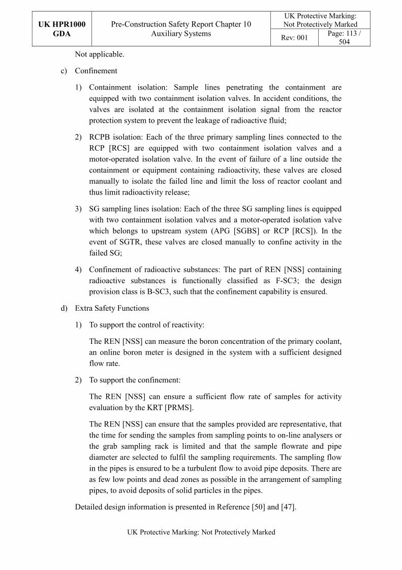
UK HPR1000
GDA
Pre-Construction Safety Report Chapter 10 Auxiliary Systems
UK Protective Marking: Not Protectively Marked
Rev: 001 Page: 113 /
504
UK Protective Marking: Not Protectively Marked
Not applicable.
c) Confinement
1) Containment isolation: Sample lines penetrating the containment are equipped with two containment isolation valves. In accident conditions, the valves are isolated at the containment isolation signal from the reactor protection system to prevent the leakage of radioactive fluid;
2) RCPB isolation: Each of the three primary sampling lines connected to the RCP [RCS] are equipped with two containment isolation valves and a motor-operated isolation valve. In the event of failure of a line outside the containment or equipment containing radioactivity, these valves are closed manually to isolate the failed line and limit the loss of reactor coolant and thus limit radioactivity release;
3) SG sampling lines isolation: Each of the three SG sampling lines is equipped with two containment isolation valves and a motor-operated isolation valve which belongs to upstream system (APG [SGBS] or RCP [RCS]). In the event of SGTR, these valves are closed manually to confine activity in the failed SG;
4) Confinement of radioactive substances: The part of REN [NSS] containing radioactive substances is functionally classified as F-SC3; the design provision class is B-SC3, such that the confinement capability is ensured.
d) Extra Safety Functions
1) To support the control of reactivity:
The REN [NSS] can measure the boron concentration of the primary coolant, an online boron meter is designed in the system with a sufficient designed flow rate.
2) To support the confinement:
The REN [NSS] can ensure a sufficient flow rate of samples for activity evaluation by the KRT [PRMS].
The REN [NSS] can ensure that the samples provided are representative, that the time for sending the samples from sampling points to on-line analysers or the grab sampling rack is limited and that the sample flowrate and pipe diameter are selected to fulfil the sampling requirements. The sampling flow in the pipes is ensured to be a turbulent flow to avoid pipe deposits. There are as few low points and dead zones as possible in the arrangement of sampling pipes, to avoid deposits of solid particles in the pipes.
Detailed design information is presented in Reference [50] and [47].
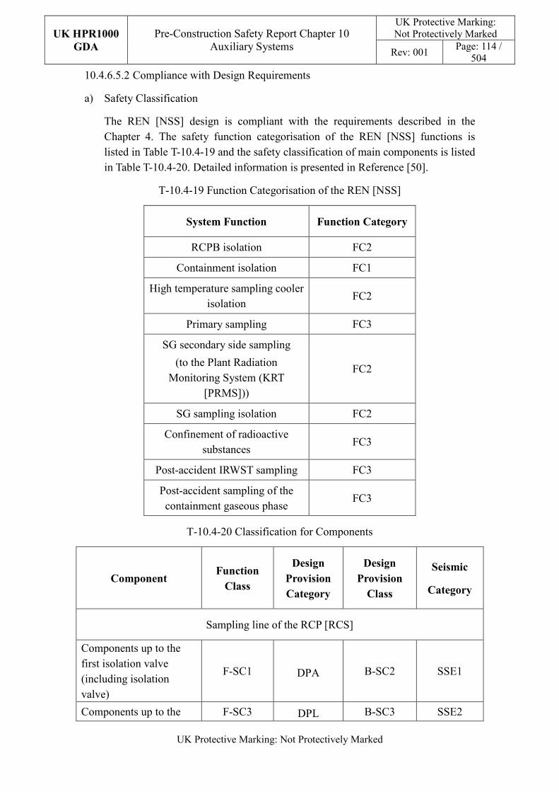
UK HPR1000
GDA
Pre-Construction Safety Report Chapter 10 Auxiliary Systems
UK Protective Marking: Not Protectively Marked
Rev: 001 Page: 114 /
504
UK Protective Marking: Not Protectively Marked
10.4.6.5.2 Compliance with Design Requirements
a) Safety Classification
The REN [NSS] design is compliant with the requirements described in the Chapter 4. The safety function categorisation of the REN [NSS] functions is listed in Table T-10.4-19 and the safety classification of main components is listed in Table T-10.4-20. Detailed information is presented in Reference [50].
T-10.4-19 Function Categorisation of the REN [NSS]
System Function Function Category
RCPB isolation FC2
Containment isolation FC1
High temperature sampling cooler isolation
FC2
Primary sampling FC3
SG secondary side sampling
(to the Plant Radiation Monitoring System (KRT
[PRMS]))
FC2
SG sampling isolation FC2
Confinement of radioactive substances
FC3
Post-accident IRWST sampling FC3
Post-accident sampling of the containment gaseous phase
FC3
T-10.4-20 Classification for Components
Component Function
Class
Design
Provision
Category
Design
Provision
Class
Seismic
Category
Sampling line of the RCP [RCS]
Components up to the first isolation valve (including isolation valve)
F-SC1 DPA B-SC2 SSE1
Components up to the F-SC3 DPL B-SC3 SSE2
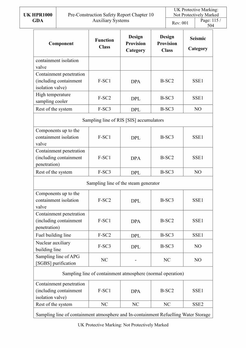
UK HPR1000
GDA
Pre-Construction Safety Report Chapter 10 Auxiliary Systems
UK Protective Marking: Not Protectively Marked
Rev: 001 Page: 115 /
504
UK Protective Marking: Not Protectively Marked
Component Function
Class
Design
Provision
Category
Design
Provision
Class
Seismic
Category
containment isolation valve
Containment penetration (including containment isolation valve)
F-SC1 DPA B-SC2 SSE1
High temperature sampling cooler
F-SC2 DPL B-SC3 SSE1
Rest of the system F-SC3 DPL B-SC3 NO
Sampling line of RIS [SIS] accumulators
Components up to the containment isolation valve
F-SC1 DPL B-SC3 SSE1
Containment penetration (including containment penetration)
F-SC1 DPA B-SC2 SSE1
Rest of the system F-SC3 DPL B-SC3 NO
Sampling line of the steam generator
Components up to the containment isolation valve
F-SC2 DPL B-SC3 SSE1
Containment penetration (including containment penetration)
F-SC1 DPA B-SC2 SSE1
Fuel building line F-SC2 DPL B-SC3 SSE1
Nuclear auxiliary building line
F-SC3 DPL B-SC3 NO
Sampling line of APG [SGBS] purification
NC - NC NO
Sampling line of containment atmosphere (normal operation)
Containment penetration (including containment isolation valve)
F-SC1 DPA B-SC2 SSE1
Rest of the system NC NC NC SSE2
Sampling line of containment atmosphere and In-containment Refuelling Water Storage
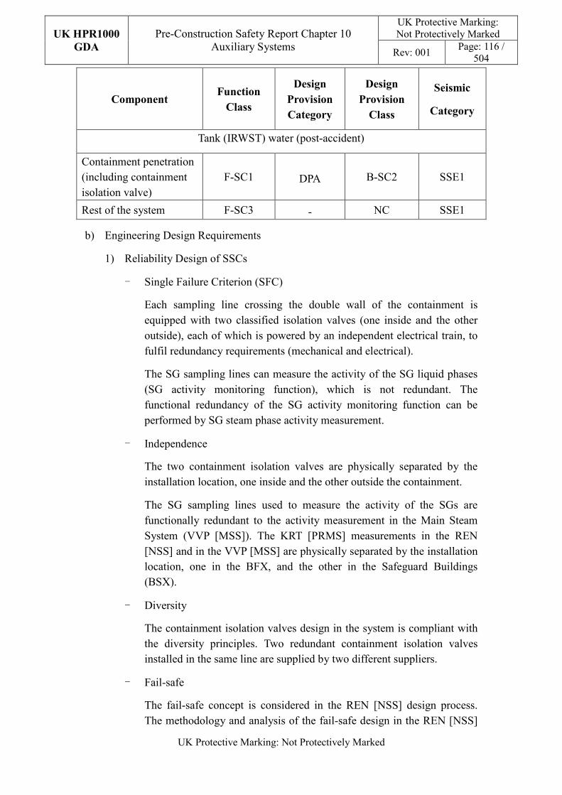
UK HPR1000
GDA
Pre-Construction Safety Report Chapter 10 Auxiliary Systems
UK Protective Marking: Not Protectively Marked
Rev: 001 Page: 116 /
504
UK Protective Marking: Not Protectively Marked
Component Function
Class
Design
Provision
Category
Design
Provision
Class
Seismic
Category
Tank (IRWST) water (post-accident)
Containment penetration (including containment isolation valve)
F-SC1 DPA B-SC2 SSE1
Rest of the system F-SC3 - NC SSE1
b) Engineering Design Requirements
1) Reliability Design of SSCs
- Single Failure Criterion (SFC)
Each sampling line crossing the double wall of the containment is equipped with two classified isolation valves (one inside and the other outside), each of which is powered by an independent electrical train, to fulfil redundancy requirements (mechanical and electrical).
The SG sampling lines can measure the activity of the SG liquid phases (SG activity monitoring function), which is not redundant. The functional redundancy of the SG activity monitoring function can be performed by SG steam phase activity measurement.
- Independence
The two containment isolation valves are physically separated by the installation location, one inside and the other outside the containment.
The SG sampling lines used to measure the activity of the SGs are functionally redundant to the activity measurement in the Main Steam System (VVP [MSS]). The KRT [PRMS] measurements in the REN [NSS] and in the VVP [MSS] are physically separated by the installation location, one in the BFX, and the other in the Safeguard Buildings (BSX).
- Diversity
The containment isolation valves design in the system is compliant with the diversity principles. Two redundant containment isolation valves installed in the same line are supplied by two different suppliers.
- Fail-safe
The fail-safe concept is considered in the REN [NSS] design process. The methodology and analysis of the fail-safe design in the REN [NSS]
UK HPR1000
GDA
Pre-Construction Safety Report Chapter 10 Auxiliary Systems
UK Protective Marking: Not Protectively Marked
Rev: 001 Page: 117 /
504
UK Protective Marking: Not Protectively Marked
system is presented in the Reference [47]. After comprehensive analysis, other measures such as redundancy are used to improve safety in order to avoid the potential safety risks that may be introduced by “fail-safe” design on power plant.
- Ageing and Degradation
The service life of some of the main components of the system is 60 years. For example the sample backfeed pump, sample backfeed tank, high/low temperature sampling coolers, etc.
The REN [NSS] considers the requirements stated in Sub-chapter 10.2.4, and the design considerations and measures described in Sub-chapter 10.2.4 are applied in the design of the REN [NSS].
Detailed design arrangement of EMIT and equipment monitoring is presented in the SDM, Reference [49].
2) Human Factors
The REN [NSS] considers the requirements stated in Sub-chapter 10.2.4, and the design considerations and measures described in Sub-chapter 10.2.4 are applied in the design of the REN [NSS].
The REN [NSS] does not require short term operator intervention. Detailed information about automatic control design of the system is presented in the SDM, Reference [49].
3) Autonomy
- Autonomy with respect to Operators
The design principles relevant to the autonomy with respect to operators are detailed in Sub-chapter 10.2.4. The design of the REN [NSS] fulfils these principles via control functional design. Detailed information is presented in the SDM, Reference [49].
- Autonomy with respect to the Heat Sink
Not applicable.
- Autonomy with respect to Power Supply Systems
The safety classified components, such as the primary sample backfeed pump, are all provided with emergency diesel generators.
4) Other design requirements
- Prevention of Harmful Interactions of Systems Important to Safety
When the water level of the primary sample backfeed tank exceeds the
UK HPR1000
GDA
Pre-Construction Safety Report Chapter 10 Auxiliary Systems
UK Protective Marking: Not Protectively Marked
Rev: 001 Page: 118 /
504
UK Protective Marking: Not Protectively Marked
overflow level, and that overflow to the RPE [VDS] fails, a protection signal is triggered and all the sampling lines (RCP [RCS], RIS [SIS] RHR, RCV [CVCS]) are isolated to prevent samples from overflowing into the Gaseous Waste Treatment System (TEG [GWTS]), causing damage to equipment of the TEG [GWTS].
- Considerations Related to the Electrical Power Grid
The design of active components such as the sample backfeed pumps in the REN [NSS] has taken disturbances in the electrical power grid into consideration. Detailed design information of the electrical power grid is presented in Reference [50].
c) Equipment Qualification
All the components of the REN [NSS] required performing safety functions, such as the containment isolation valves, are capable of operating under both normal and accident conditions. As a result, the components can withstand the most adverse environmental conditions expected.
All the seismically classified components of the REN [NSS] shall be capable of operating during and after the SSE. The secondary high temperature coolers and the containment isolation valves are seismic designed and qualified for the SSE load.
Principles of equipment qualification classification of the system are presented in Reference [50]. Detailed information related to the system equipment qualification is presented in Reference [47].
d) Protection Design against Internal and External Hazards
The REN [NSS] considers the requirements stated in Sub-chapter 10.2.4, the REN [NSS] is required to consider several external and internal hazards, and the corresponding protection measures are described below.
1) External Hazards
FC1 and FC2 classified equipment of the REN [NSS] considers the protection against external hazards.
- Earthquake
REN [NSS] safety-classified components are arranged in SSE1-classified structures, because seismic loads of SSE are considered in the design.
- Other external hazards
REN [NSS] safety-classified components are protected against external
UK HPR1000
GDA
Pre-Construction Safety Report Chapter 10 Auxiliary Systems
UK Protective Marking: Not Protectively Marked
Rev: 001 Page: 119 /
504
UK Protective Marking: Not Protectively Marked
hazards by civil structures. Specific protection design is presented in Reference [48].
2) Internal Hazards
FC1 and FC2 classified equipment of the REN [NSS] considers protection against internal hazards. For the components in the same building, separation and different elevation are applied to eliminate or minimise CCF induced by internal hazards. Specific protection design is presented in Reference [48].
e) Commissioning
Before operation, commissioning and tests are carried out to verify that the performance of the REN [NSS] meets the design requirements. The methodology of system commissioning programme design is presented in Reference [31]. The main commissioning test of the REN [NSS] includes tests for pumps, tanks, the heat exchanger, on-line analyser and sampling grove box. Further detailed site specific arrangements for the UK HPR1000 commissioning activities will be presented during the nuclear site licencing phase in conjunction with the site licensee.
f) Examination, Inspection, Maintenance and Testing
1) Inspections and Surveillance
In-service inspection is implemented for the equipment of the REN [NSS], including the primary backfeed tank and high temperature sampling coolers for primary and secondary sampling.
2) Maintenance
Instrument maintenance of the REN [NSS] includes calibration and validation of chemical analysers (boron meter, hydrogen analyser, oxygen analyser, sodium meter, pH meter and conductivity meter). The maintenance period depends on:
- Plant operation technical specifications;
- Feedback of operating experience;
- Manufactures’ recommendations.
Maintenance of the REN [NSS] valves and other mechanical equipment mainly depends on the manufacturers’ recommendations and feedback from OPEX. It’s determined according to the availability of equipment and usually performed during the shutdown state. Equipment maintenance is performed according to equipment operation and the maintenance manual.
3) Periodic Tests
UK HPR1000
GDA
Pre-Construction Safety Report Chapter 10 Auxiliary Systems
UK Protective Marking: Not Protectively Marked
Rev: 001 Page: 120 /
504
UK Protective Marking: Not Protectively Marked
Equipment performing safety functions shall be subject to periodic testing, mainly consisting of the containment isolation valves. Detailed information on components requiring periodic tests is shown in the SDM, Reference [49].
For the UK HPR1000, the periodic test design method is presented in the Reference [32].
g) Decommissioning
The design of the REN [NSS] considers decommissioning. A certain gradient is set in the pipeline layout to prevent liquid accumulation and all equipment and pipes can be drained by draining lines.
h) Material Selection
All parts of the REN [NSS] are made of stainless steel to prevent corrosion and facilitate decontamination after sampling. Only the pipelines transporting the cooling water are made of carbon steel.
i) Special Thermal-hydraulic Phenomena
In order to ensure the function reliability of the system and to prevent challenges to performing the safety functions, the hydraulic phenomena listed below are considered in REA [RBWMS] design:
1) Phenomenon regarding the dead leg;
2) Phenomenon regarding the hot water and cold water mixing;
3) Phenomenon regarding the thermal stratification;
4) Phenomenon regarding the water hammer.
j) Insulation
Insulation is mainly considered for operators’ safety. Accessible equipment or pipelines with a high surface temperature is insulated to prevent burns.
Insulation is required since the operating temperature of the following lines is above 60 °C:
- The sampling lines from the RCP [RCS] up to the high temperature sampling cooler;
- The sampling lines from the RIS [SIS] RHR heat exchangers up to the high temperature sampling cooler;
- The sampling lines from the end of the boron concentration monitoring circuit up to the sampling cooler;
- The sampling lines from the SG up to the high temperature sampling
UK HPR1000
GDA
Pre-Construction Safety Report Chapter 10 Auxiliary Systems
UK Protective Marking: Not Protectively Marked
Rev: 001 Page: 121 /
504
UK Protective Marking: Not Protectively Marked
cooler.
Anti-condensation measures are required for the lines of the Operational Chilled Water System (DER [OCWS]) and the shell side of the low temperature sampling coolers since the operating temperature of the DER [OCWS] is between 7°C and 12°C.
10.4.6.6 Simplified Diagrams
Simplified system diagrams are presented in Figures F-10.4-4 and F-10.4-5, the detailed system functional diagram is in Reference [51].
10.4.7 Fuel Pool Cooling and Treatment System (PTR [FPCTS])
PTR [FPCTS] ensures a sub-critical margin and removes decay heat for the fuel assemblies stored in the SFP. The cooling function is performed by three cooling trains located in the BFX. Furthermore, the PTR [FPCTS] provides water purification, filling and discharge for the reactor pools, BFX pools, IRWST and the In-Vessel Retention (IVR) tank. Skimming of the reactor pools and the BFX pools is also performed by the PTR [FPCTS]. System information is presented in the SDM, Reference [52].
Safety Functional Requirements
10.4.7.1.1 Control of Reactivity
The PTR [FPCTS] does not directly contribute to the reactivity control of the reactor core and spent fuel, but shall provide a sub-critical margin for the spent fuel in the SFP.
10.4.7.1.2 Removal of Heat
The PTR [FPCTS] shall remove the decay heat of the fuel assemblies stored in the SFP in normal and accident conditions (DBC-1/2/3/4 and DEC-A) by cooling the SFP.
For the residual heat removal, the water temperature of the SFP shall be limited to ensure the spent fuel cooling.
The level of water in the pools shall be maintained to prevent uncovering the spent fuel during fuel assembly handling.
10.4.7.1.3 Confinement
The PTR [FPCTS] shall ensure the confinement of radioactive substances to prevent discharge to the environment by the isolation of the containment.
10.4.7.1.4 Extra Safety Functions
The PTR [FPCTS] shall perform extra safety functions, such as:
a) Monitoring of the reactor pools level, SFP level and temperature in normal and
UK HPR1000
GDA
Pre-Construction Safety Report Chapter 10 Auxiliary Systems
UK Protective Marking: Not Protectively Marked
Rev: 001 Page: 122 /
504
UK Protective Marking: Not Protectively Marked
accident conditions (DBC-1/2/3/4 and DEC-A) to provide information supporting the removal of heat safety function;
b) Detection of a decrease in the water level in the SFP in normal and accident conditions (DBC-1/2/3/4 and DEC-A);
c) Detection of a high or low temperature in the SFP in normal and accident conditions (DBC-1/2/3/4 and DEC-A).
Detailed safety functional requirements are presented in SDM, Reference [53].
10.4.7.2 Design Requirements
The general design requirements of the nuclear auxiliary systems need to be considered are shown in Sub-chapter 10.2.4, among which the following requirements are not applicable for the PTR [FPCTS] system:
a) Autonomy with respect to the Heat Sink
Not applicable, the PTR [FPCTS] system doesn’t provide heat sink to the power plant.
b) Prevention of Harmful Interactions of Systems Important to Safety
Not applicable, there are no harmful interactions between PTR [FPCTS] and other systems important to safety.
c) Insulation
Not applicable, the temperature of the fluid in pipelines and components of the PTR [FPCTS] doesn’t exceed 50 °C in normal operation.
The substantiation analysis of the PTR [FPCTS] system to other design requirements is shown in the Section 10.4.7.5.2 Compliance with Design Requirements.
10.4.7.3 Design Bases
This sub-chapter aims to provide the main assumptions considered in the PTR [FPCTS] design.
10.4.7.3.1 General Assumptions
a) Safety Classification
The safety classification for the PTR [FPCTS] is based on the following methodology:
The containment isolation function is required to confine the radioactive substances in DBC conditions, the function category is FC1.
The isolation function of the SFP cooling trains and of the draining lines at the bottom of the BRX and BFX pools (except the SFP) is required to stop the
UK HPR1000
GDA
Pre-Construction Safety Report Chapter 10 Auxiliary Systems
UK Protective Marking: Not Protectively Marked
Rev: 001 Page: 123 /
504
UK Protective Marking: Not Protectively Marked
drainage of the pools in DBC conditions, the function category is FC1.
The cooling function of the SFP is required to remove the residual heat in accident conditions, the function category is FC2.
The accident overflow function from the BRX Pools to the IRWST is required to maintain the dynamic balance between the reactor pool and IRWST in accident conditions, the function category is FC1.
The accident water make-up function of the SFP is required to compensate for the water loss during the event of total loss of cooling trains, the function category is FC3.
b) Ageing and Degradation
According to Chapter 2, the operational design life of the UK HPR1000 is 60 years. The main components of the PTR [FPCTS] are required to have a service life of 60 years.
c) Considerations Related to the Electrical Power Grid
The functionality of items important to safety at the nuclear power plant shall not be compromised by disturbances in the electrical power grid, including anticipated variations in the voltage and frequency of the grid supply.
10.4.7.3.2 Design Assumptions
a) Control of Reactivity
There is no quantitative assumption for the PTR [FPCTS].
b) Removal of Heat
For residual heat removal, the PTR [FPCTS] cooling trains shall meet the following assumptions:
1) The design basis heat load is considered to be the maximum value in the SFP during reactor power operation and reactor complete discharge mode;
2) The water temperature of the SFP shall not exceed the limited values as follows: 50°C under the DBC-1 conditions (the maximum temperature of cooling water is 38°C) and 80°C under the DBC-2/3/4 conditions (the maximum temperature of cooling water is 45°C);
3) The water temperature of the SFP shall not exceed 95°C under DEC conditions except following the total loss of cooling (the maximum temperature of cooling water is 45°C);
4) The cooling trains can be recovered when water boils in the SFP.
Considering the thermal load of the SFP and the design of heat exchangers,
UK HPR1000
GDA
Pre-Construction Safety Report Chapter 10 Auxiliary Systems
UK Protective Marking: Not Protectively Marked
Rev: 001 Page: 124 /
504
UK Protective Marking: Not Protectively Marked
the minimum flow rate of the cooling train is designed as {****/*}. The level of water in the pools shall not be lower than +14.1m in the event of drainage accidents to prevent uncovering of the fuel assembly in handling.
In the accident condition of total loss of the cooling trains, the flowrate of the SFP emergency makeup water is designed based on the maximum thermal load.
c) Confinement
There is no quantitative design assumption for the PTR [FPCTS].
d) Extra Safety Functions
There is no quantitative design assumption for the PTR [FPCTS].
10.4.7.4 System Description and Operation
10.4.7.4.1 System Description
a) General System Description
The PTR [FPCTS] consists of four parts which are described as below.
1) SFP Cooling
Three cooling trains are located in the fuel building for the PTR [FPCTS]. Each cooling train is equipped with one suction line, one SFP cooling pump, one heat exchanger and one discharge line. Cooling trains A and B are supplied with cooling water by train A and B of the RRI [CCWS], while the backup cooling is provided by train A and B of the ECS [ECS]. Train C is supplied with cooling water only by train C of the RRI [CCWS].
The trains are separately supplied with power by different electrical divisions. Trains A and B are supplied with backup power by Emergency Diesel Generators (EDGs) and SBO diesel generators, and train C is supplied with backup power only by EDGs.
Each cooling train is arranged with two motorised isolation valves in series at the suction, which can receive the automatic isolation signals in the case of low liquid level of the SFP. These two motorised isolation valves are supplied with power by different electrical divisions. Each cooling train is arranged with one check valve at the discharge to prevent siphoning caused by an upstream break.
There are cross-connections between the trains downstream of the three cooling pumps. The pump in one train can be connected to the heat exchanger of another train if necessary, thus a new cooling train to cool the SFP can be arranged.
UK HPR1000
GDA
Pre-Construction Safety Report Chapter 10 Auxiliary Systems
UK Protective Marking: Not Protectively Marked
Rev: 001 Page: 125 /
504
UK Protective Marking: Not Protectively Marked
The suction and discharge of the cooling trains (except the suction of train C) are provided with siphon breakers to prevent an unacceptable decrease in SFP water level after accidental draining. The suction location of train C is lower than trains A and B. When there is a break on train A or B, and the pool liquid level decreases below the elevation of the train A or B penetrations, train C can still operate to cool the SFP.
The cooling train sampling is used to inspect the water quality of the SFP, including boron concentration, chemical impurity content and radioactivity level.
2) Purification and Water Transfer
The maximum operating temperature of purification shall consider the technological limitation of the resin, and the flowrate of purification is considered to be able to purify the water in the SFP or the reactor pool in about 24 hours.
The filtration filters are fine enough to ensure clarity of the pool water so that fuel handling operations can be monitored under water and to ensure the protection of the operators.
The purification system of the SFP is equipped with one purification pump, one filter, one mixed bed demineraliser and one resin trap filter. The pipeline from the bottom of the fuel building pools (except the SFP) to the pump inlet is equipped with two motorised isolation valves which will be automatically closed in the case of low water level in the SFP. In the case of accidental draining, these two isolation valves can ensure automatic double isolation.
The purification system of the reactor pool is equipped with one purification pump and one filter. The pipeline from the bottom of the reactor pool to the pump inlet is also equipped with two motorised isolation valves.
The purification pumps are supplied with power by different electrical divisions. These two pumps can be backed up by each other. The reactor pool purification filter can be the backed up by the SFP purification filter.
If required, the purification unit for the SFP can also be used for purifying of the IRWST and IVR tank.
The purification pumps can also be used to transfer water between the fuel building transfer compartment and the cask loading pit. In this case, the purification unit (including two filters and the demineraliser) is bypassed.
Before unloading, the purification pumps can be used to fill the reactor pool from the IRWST. After reloading, the water in the reactor pool can be drained to the IRWST by gravitational drain pipeline or by the purification pumps.
UK HPR1000
GDA
Pre-Construction Safety Report Chapter 10 Auxiliary Systems
UK Protective Marking: Not Protectively Marked
Rev: 001 Page: 126 /
504
UK Protective Marking: Not Protectively Marked
3) Skimming
Surface skimming ensures the sufficient clarity of the water and also enables the reduction of radiation due to activation of impurities at the pool surface.
The skimming system for the SFP is equipped with one skimming pump and one filter.
The skimming system for the reactor pool uses a floating skimming device to ensure that the skimming function is available when the pool liquid level changes. This circuit is equipped with one skimming pump. The outlet of the skimming pump is connected to the inlet of the reactor pool purification pump.
4) Water Return to the IRWST
In the event of a Loss of Coolant Accident (LOCA) during power operation, the draining lines at the bottom of the reactor pools in the PTR [FPCTS] ensure that water is returned to the IRWST for the operation of the RIS [SIS] pumps.
After shutdown, when a small break which cannot be isolated occurs on the primary circuit, or a when TLOCC or SBO occurs, the RIS [SIS] pump is started to inject fluid into the primary circuit. Furthermore, the isolation valves on the accident overflow line for the reactor pool are opened to achieve a dynamic balance between the reactor pool and the IRWST to maintain an appropriate water level.
5) Filling and Water Makeup
The REA [RBWMS] provides the initial water filling or the borated water makeup to the SFP, IRWST and IVR tank.
The SED [DWDS (NI)] can be used to compensate for the normal evaporation loss of the SFP.
In the case of total loss of the PTR [FPCTS] cooling trains, the following means can be used for the SFP makeup:
- The gravitational makeup pipeline of the Secondary Passive Heat Removal System (ASP [SPHRS]) water tank;
- The emergency makeup line through the external makeup interface.
b) Description of Main Equipment
The main equipment of the PTR [FPCTS] is described below, and detailed information of other equipment is presented in the SDM, Reference [54].
1) Cooling Pumps
UK HPR1000
GDA
Pre-Construction Safety Report Chapter 10 Auxiliary Systems
UK Protective Marking: Not Protectively Marked
Rev: 001 Page: 127 /
504
UK Protective Marking: Not Protectively Marked
Each cooling train has a cooling pump to drive fluid from the SFP to the exchanger.
The cooling pumps are horizontal centrifugal pumps. The nominal flowrate of the pump is based on the required mass flowrate of the exchanger. The following table gives the characteristics of the pumps:
T-10.4-21 Characteristics of the Cooling Pumps
Parameters Value Unit
Type Centrifugal Pump
Nominal Flowrate 640 m3/h
Discharge Head at Nominal Flowrate 36 mWc
Material Stainless Steel
2) Exchangers
Each cooling train has an exchanger to remove the decay heat of the fuel assemblies stored in the SFP. The design flowrate ensure that the decay heat of the SFP can be removed in normal and accident conditions. The following table gives the characteristics of the exchangers:
T-10.4-22 Characteristics of the Exchanger
Parameters Value Unit
Type Shell & Tube
Hot Side Cold Side ---
Design Thermal Load {*****} MW
Medium Borated Water Component Cooling Water ---
Design Pressure 1 2.9 (Train A and B) 1.35 (Train C)
MPa (g)
Design Temperature 110 90 °C
Design Flowrate {***} {***} (All Normal Operation Modes Except
Refuelling Cold Shutdown and Reactor Completely
Discharge Mode, it is then supplied by the RRI
[CCWS]), {***} (Refuelling Cold Shutdown and Reactor Completely Defueling
Mode, it is then supplied by the RRI [CCWS])
{***} (supplied by the ECS
t/h
UK HPR1000
GDA
Pre-Construction Safety Report Chapter 10 Auxiliary Systems
UK Protective Marking: Not Protectively Marked
Rev: 001 Page: 128 /
504
UK Protective Marking: Not Protectively Marked
Parameters Value Unit
[ECS]
Material SS CS ---
c) Description of Main Layout
The three PTR [FPCTS] cooling trains are located in three different areas in the BFX, which are physically separated from each other.
The filters and demineraliser are located in the BNX.
The skimming pump of the reactor pool, pipelines for purification and water transfer connected to the BRX pools are located in the BRX.
The rest of the PTR [FPCTS] is located in the BFX.
d) Description of System Interfaces
1) ASP [SPHRS]
When the cooling trains fail, the ASP [SPHRS] will make up water to the SFP to compensate for the loss due to evaporation.
2) ECS [ECS]
The ECS [ECS] cools the heat exchanger of train A and B.
3) The Containment Heat Removal System (EHR [CHRS])
The PTR [FPCTS] can purify the IVR tank.
4) RCV [CVCS]
For the PTR [FPCTS], the RCV [CVCS] can:
Provide suction from the IRWST for purification or water transfers. The purification pump suction is connected to the RCV [CVCS] lines allowing suction from the IRWST;
Transfer nitrogen from the Nitrogen Distribution System (SGN [NDS]) to perform maintenance operations on the demineraliser.
5) REA [RBWMS]
The REA [RBWMS] carries out initial filling of the IRWST, IVR tank, SFP and one of the compartments of the transfer compartment and cask loading pit with borated water through the PTR [FPCTS] lines.
The borated water makeup of the SFP, IRWST and IVR tank can also be carried out via the REA [RBWMS].
6) REN [NSS]
UK HPR1000
GDA
Pre-Construction Safety Report Chapter 10 Auxiliary Systems
UK Protective Marking: Not Protectively Marked
Rev: 001 Page: 129 /
504
UK Protective Marking: Not Protectively Marked
The REN [NSS] is able to take samples from the SFP, IRWST, IVR tank and the reactor pool to monitor the radioactivity and boron concentration.
7) RIS [SIS]
The PTR [FPCTS] enables water to drain from the reactor pool to the IRWST. This makeup to the IRWST ensures a sufficient level in the IRWST for the operation of the RIS [SIS]/EHR [CHRS] pumps required in a small LOCA, SBO or TLOCC after the reactor pressure vessel is opened.
The PTR [FPCTS] can also purify the IRWST.
8) RRI [CCWS]
The RRI [CCWS] cools the heat exchangers of the three cooling trains.
9) SED [DWDS (NI)]
The SED [DWDS (NI)] provides makeup to the SFP to compensate for normal evaporation.
e) Description of I&C
According to the PTR [FPCTS] functions and configurations, the main control and monitoring requirements are as follows:
1) Containment Isolation
The PTR [FPCTS] closes the containment isolation valves automatically when the signal of containment first stage isolation is received from the reactor protection system.
2) Volume Control of the SFP
The level set points of the SFP are arranged to avoid the loss of water and uncovering of the fuel assemblies. When the level in the SFP decreases, automatic isolating actions will be implemented.
The level of the SFP is monitored by redundant sensors.
3) Volume Control of the Reactor Pool
The level set points of the reactor pool are arranged to avoid the loss of water and uncovering of a fuel assembly during handling. When the level decreases, the valves at the bottom of the reactor pool and at the suction of the RIS [SIS] trains will be isolated.
The level of the reactor pool is monitored by redundant sensors.
4) Cooling of the SFP
The start-up operation of the cooling pumps can be carried out manually by
UK HPR1000
GDA
Pre-Construction Safety Report Chapter 10 Auxiliary Systems
UK Protective Marking: Not Protectively Marked
Rev: 001 Page: 130 /
504
UK Protective Marking: Not Protectively Marked
operators in the MCR.
The temperature of the SFP is monitored by redundant sensors. The flowrate of each cooling train is also monitored by sensor to ensure the cooling function.
10.4.7.4.2 System Operation
a) Plant Normal Conditions
1) Cooling Trains of the SFP
The SFP cooling trains operate continuously as long as there are spent fuel assemblies stored in the pool.
During power operation, one cooling train is required to be in operation. The other two cooling trains are on standby.
During normal refuelling shutdown, two cooling trains operate simultaneously, and one is left on standby.
During normal operation, the flowrate of each cooling train for the SFP is {****/*}, and the flowrate at the RRI [CCWS] side is {****/*} (during refuelling cold shutdown and reactor complete discharge mode) or {****/*} (except refuelling cold shutdown and reactor complete discharge mode).
2) Purification and Skimming of the SFP
SFP purification is undertaken during long-term operation. When the SFP purification units are used to purify the IRWST, the purification of the SFP will be temporarily interrupted. The reactor pool purification pump and the SFP purification pump can be backed up by each other. During replacement of the demineraliser resin or replacement of filter element, the purification is interrupted.
SFP skimming operates intermittently according to the surface impurity degree in the SFP.
3) Water Makeup of the SFP
When it is required to make up the borated water to the SFP after a leak, this is performed by the REA [RBWMS].
The SED [DWDS (NI)] can compensate for the normal evaporation of water in the SFP.
4) Purification and Skimming of the BRX Pools
During power operation, the reactor pool purification filter can be backed up by the SFP purification filter.
UK HPR1000
GDA
Pre-Construction Safety Report Chapter 10 Auxiliary Systems
UK Protective Marking: Not Protectively Marked
Rev: 001 Page: 131 /
504
UK Protective Marking: Not Protectively Marked
During refuelling shutdown, the reactor pool purification pump and the reactor pool filter can be put into operation as well as the skimming system to ensure sufficient visibility when the reactor pool is filled with water. The reactor pool can also be purified by the RCV [CVCS] purification unit.
The IRWST and IVR tank can be purified by the SFP purification unit through the EHR [CHRS]/RCV [CVCS] connections if required.
5) Filling and Draining of the Reactor Pool
Before unloading, the purification pumps can fill the reactor pool. After reloading, the purification pumps can also drain the reactor pool to the IRWST. The water in the reactor pool can also flow gravitationally to the IRWST through the pipeline at the bottom of the reactor pool.
b) Plant Accident Conditions
In DBC conditions, one cooling train is sufficient to meet the requirements of the SFP cooling considering a single failure. The SFP temperature is maintained below 80°C.
In the conditions of a SBO or TLOCC, the RRI [CCWS] is not available and the ECS [ECS] is required to provide the cooling water. The flowrate of the cooling train is {****/*} and the flowrate at the ECS [ECS] side is {****/*}. The SFP temperature is maintained below 95°C.
When total loss of the PTR [FPCTS] cooling trains occurs, the operator can use the ASP [SPHRS] makeup line or external makeup connection to compensate for the loss of water due to boiling.
After shutdown, when a small break which cannot be isolated occurs on the primary circuit, or a TLOCC or SBO occurs, the RIS [SIS] pump is started to inject fluid into the primary circuit. Furthermore the isolation valves on the accident overflow line for reactor pool are opened to achieve a dynamic balance between the reactor pool and the IRWST to maintain an appropriate water level.
10.4.7.5 Preliminary Design Substantiation
In this section, the system design is demonstrated to satisfy the safety functional requirements presented in Sub-chapter 10.4.7.1 and the general design requirements stated in Sub-chapter 10.2.4. Review of the consistency of the system design against the newly developed principles is currently being undertaken.
10.4.7.5.1 Compliance with Safety Functional Requirements
The system configuration and the capability of the components complies with the safety functional requirements, detailed system design information is presented in the SDM, Reference [53], [54], [55]. Furthermore, design substantiation for the PTR
UK HPR1000
GDA
Pre-Construction Safety Report Chapter 10 Auxiliary Systems
UK Protective Marking: Not Protectively Marked
Rev: 001 Page: 132 /
504
UK Protective Marking: Not Protectively Marked
[FPCTS] has been estimated in the fault study in Chapters 12 and 13.
a) Control of Reactivity
Not applicable.
b) Removal of Heat
The PTR [FPCTS] is designed with three cooling trains to remove the decay heat of the fuel assemblies stored in the SFP in DBC and DEC accident conditions.
During normal power operation, the SFP average temperature is maintained below 50°C by operating one cooling train of the PTR [FPCTS]. During the reactor refuelling period, the SFP average temperature is maintained below 50°C by operating two cooling trains of the PTR [FPCTS]. The relevant analysis is presented in the Pre-Construction Environmental Report (PCER) Chapter 3, Reference [195].
In the accident conditions of DBC-2/3/4, the SFP average temperature is maintained below 80°C by operating one cooling train of the PTR [FPCTS]. In the event of a SBO or TLOCC, the SFP average temperature is maintained below 95°C by operating one cooling train of the PTR [FPCTS].
When total loss of the PTR [FPCTS] cooling trains occurs, there are two ways to make up water to the SFP to compensate for the loss of water due to boiling. One way is the ASP [SPHRS] gravitational makeup, and the other is external water makeup. The flowrate of the makeup water is more than 50m3/h.
Pipe penetrations which are equipped with siphon breakers and pipe suctions which are without siphon breakers are all set above the fuel assemblies in the pool to prevent the direct uncovering of fuel assemblies either in the storage racks or during handling in the event of a pipe break. Various measures are considered to guarantee the water level requirements for SFP during normal operation and accident conditions, such as leakage monitoring and collection for the SFP, water level monitoring for the SFP, the arrangement of elevations of connected pipelines, siphon breaking for connected pipelines and automatic isolation actions when the pool level decreases.
c) Confinement
To ensure the integrity of the containment, each containment penetration in the PTR [FPCTS] is equipped with two containment isolations valves. One motor-operated valve outside the containment and one motor-operated or check valve inside the containment.
d) Extra Safety Functions
The PTR [FPCTS] ensures monitoring of the reactor pool and SFP level, and also
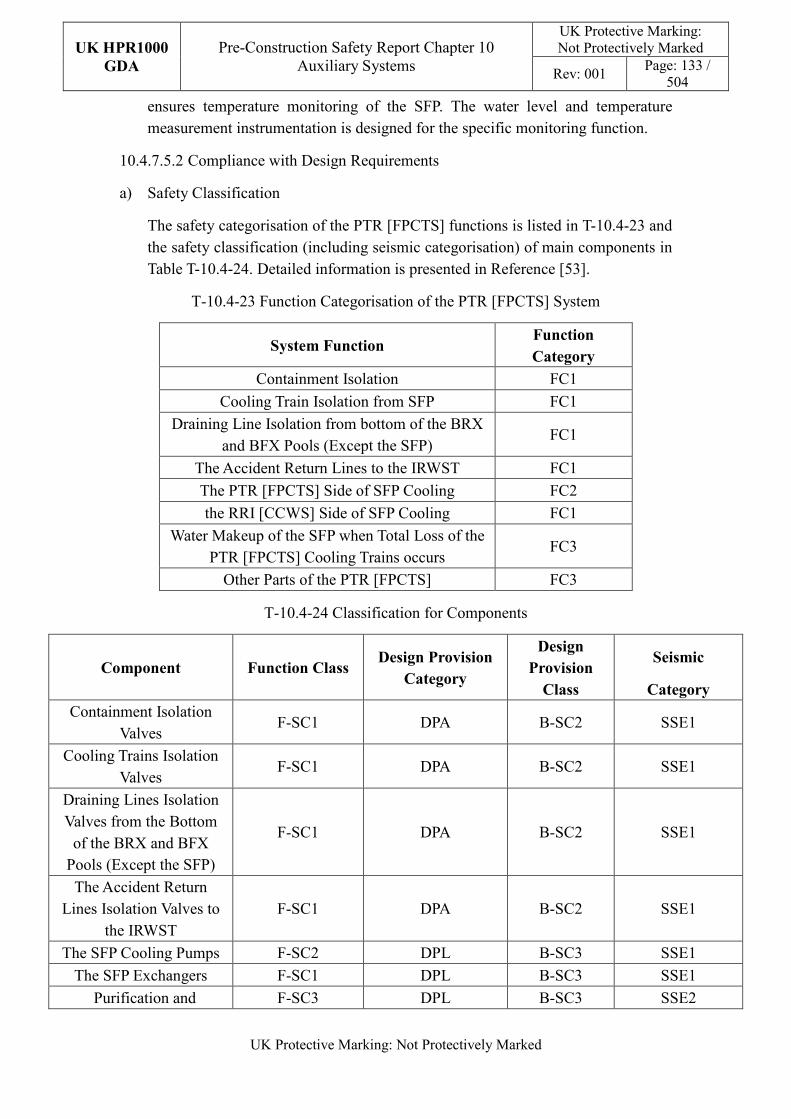
UK HPR1000
GDA
Pre-Construction Safety Report Chapter 10 Auxiliary Systems
UK Protective Marking: Not Protectively Marked
Rev: 001 Page: 133 /
504
UK Protective Marking: Not Protectively Marked
ensures temperature monitoring of the SFP. The water level and temperature measurement instrumentation is designed for the specific monitoring function.
10.4.7.5.2 Compliance with Design Requirements
a) Safety Classification
The safety categorisation of the PTR [FPCTS] functions is listed in T-10.4-23 and the safety classification (including seismic categorisation) of main components in Table T-10.4-24. Detailed information is presented in Reference [53].
T-10.4-23 Function Categorisation of the PTR [FPCTS] System
System Function Function
Category
Containment Isolation FC1
Cooling Train Isolation from SFP FC1
Draining Line Isolation from bottom of the BRX and BFX Pools (Except the SFP)
FC1
The Accident Return Lines to the IRWST FC1
The PTR [FPCTS] Side of SFP Cooling FC2
the RRI [CCWS] Side of SFP Cooling FC1
Water Makeup of the SFP when Total Loss of the PTR [FPCTS] Cooling Trains occurs
FC3
Other Parts of the PTR [FPCTS] FC3
T-10.4-24 Classification for Components
Component Function Class Design Provision
Category
Design
Provision
Class
Seismic
Category
Containment Isolation Valves
F-SC1 DPA B-SC2 SSE1
Cooling Trains Isolation Valves
F-SC1 DPA B-SC2 SSE1
Draining Lines Isolation Valves from the Bottom
of the BRX and BFX Pools (Except the SFP)
F-SC1 DPA B-SC2 SSE1
The Accident Return Lines Isolation Valves to
the IRWST F-SC1 DPA B-SC2 SSE1
The SFP Cooling Pumps F-SC2 DPL B-SC3 SSE1
The SFP Exchangers F-SC1 DPL B-SC3 SSE1
Purification and F-SC3 DPL B-SC3 SSE2
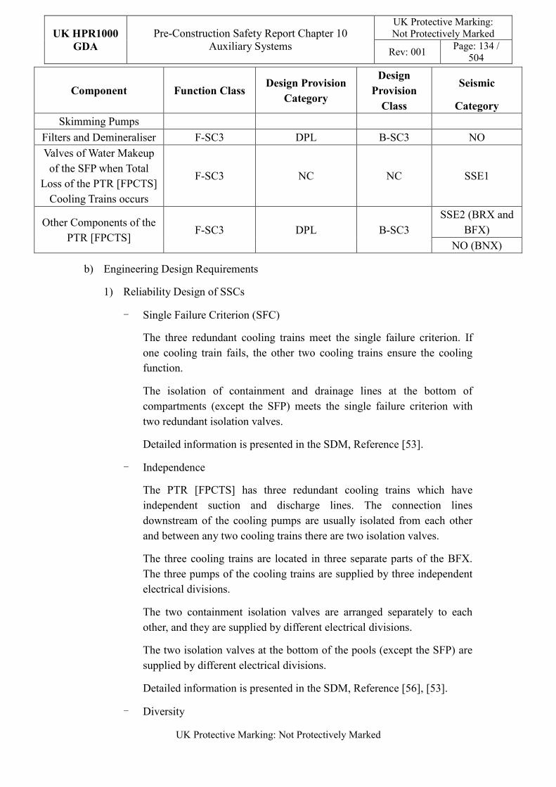
UK HPR1000
GDA
Pre-Construction Safety Report Chapter 10 Auxiliary Systems
UK Protective Marking: Not Protectively Marked
Rev: 001 Page: 134 /
504
UK Protective Marking: Not Protectively Marked
Component Function Class Design Provision
Category
Design
Provision
Class
Seismic
Category
Skimming Pumps
Filters and Demineraliser F-SC3 DPL B-SC3 NO
Valves of Water Makeup of the SFP when Total
Loss of the PTR [FPCTS] Cooling Trains occurs
F-SC3 NC NC SSE1
Other Components of the PTR [FPCTS]
F-SC3 DPL B-SC3
SSE2 (BRX and BFX)
NO (BNX)
b) Engineering Design Requirements
1) Reliability Design of SSCs
- Single Failure Criterion (SFC)
The three redundant cooling trains meet the single failure criterion. If one cooling train fails, the other two cooling trains ensure the cooling function.
The isolation of containment and drainage lines at the bottom of compartments (except the SFP) meets the single failure criterion with two redundant isolation valves.
Detailed information is presented in the SDM, Reference [53].
- Independence
The PTR [FPCTS] has three redundant cooling trains which have independent suction and discharge lines. The connection lines downstream of the cooling pumps are usually isolated from each other and between any two cooling trains there are two isolation valves.
The three cooling trains are located in three separate parts of the BFX. The three pumps of the cooling trains are supplied by three independent electrical divisions.
The two containment isolation valves are arranged separately to each other, and they are supplied by different electrical divisions.
The two isolation valves at the bottom of the pools (except the SFP) are supplied by different electrical divisions.
Detailed information is presented in the SDM, Reference [56], [53].
- Diversity
UK HPR1000
GDA
Pre-Construction Safety Report Chapter 10 Auxiliary Systems
UK Protective Marking: Not Protectively Marked
Rev: 001 Page: 135 /
504
UK Protective Marking: Not Protectively Marked
The three heat exchangers of the cooling trains are cooled respectively by the three trains of the RRI [CCWS]. The heat exchangers of cooling trains A and B of the PTR [FPCTS] are also cooled by the ECS [ECS].
The three cooling trains are supplied by EDGs. Cooling trains A and B are also supplied by SBO diesel generators.
- Fail-safe
The fail-safe concept is considered in the PTR [FPCTS] design process. The methodology and analysis of the fail-safe design for the PTR [FPCTS] system is presented in the Reference [54]. For the design of PTR [FPCTS], the top level of the wall under the sluice gate between the SFP and the two adjacent compartments is higher than the top of the fuel assemblies stored in the SFP. No pipe is arranged at the bottom of the SFP to prevent a drain out of the pool. Pipe penetrations which are equipped with siphon breakers and pipe suctions which are without siphon breakers are all set above the fuel assembly in the pool to prevent the direct uncovering of fuel assemblies either in the storage racks or during handling, in the event of a pipe break. Thus the safety of the plant is ensured even if a failure has occurred.
- Ageing and Degradation
The management of equipment ageing and degradation follows the considerations stated in Sub-chapter 10.4.2. The main components of the PTR [FPCTS] have been designed with a service life of 60 years, such as the pumps and heat exchangers.
The performance of equipment is guaranteed through life examination, inspection, maintenance and testing, as well as the monitoring during normal operation, which will ensure that ageing effects do not compromise safety performance.
2) Human Factors
The concept of human factors is taken into consideration in the system design. The PTR [FPCTS] system complies with the requirements stated in Sub-chapter 10.2.4, and design considerations and measures described in Sub-chapter 10.2.4 are applied in the design of the PTR [FPCTS].
In addition, if an action is required within 30 minutes after accidents, it is designed to occur automatically, such as the isolation of valves at the bottom of the pools when the low level threshold is reached.
Detailed design information is presented in the SDM, Reference [55].
3) Autonomy
UK HPR1000
GDA
Pre-Construction Safety Report Chapter 10 Auxiliary Systems
UK Protective Marking: Not Protectively Marked
Rev: 001 Page: 136 /
504
UK Protective Marking: Not Protectively Marked
- Autonomy with respect to Operators
The design principles relevant to the autonomy with respect to operators are detailed in Sub-chapter 10.2.4. The design of the PTR [FPCTS] fulfils these principles via control functional design; detailed information is presented in the SDM, Reference [55]. If the action is required within 30 minutes of an accident, it will be designed to occur automatically, such as the isolation of valves at the bottom of the pools when the low level threshold is reached. The design result is estimated in the safety analysis.
- Autonomy with respect to the Heat Sink
Not applicable.
- Autonomy with respect to Power Supply Systems
The design of the PTR [FPCTS] fulfils the principles relevant to the autonomy with respect to power supply systems. The three cooling trains are supplied by the EDGs, and two of them are also supplied by the SBO diesel generators.
4) Other Design Requirements
- Prevention of Harmful Interactions of Systems Important to Safety
Not applicable.
- Considerations Related to the Electrical Power Grid
Electrical power fluctuation has been considered in the equipment design such as the capability of pumps to ensure the operation of functions important to safety.
c) Equipment Qualification
All of the components required to perform safety functions are capable of operating under both normal and accident conditions. As a result, the components can withstand the most adverse environmental conditions expected.
Active components such as containment isolation valves, cooling pumps and the valves at the cooling trains shall be qualified.
All the seismically classified components shall be capable of operating during and after the SSE. The components are seismically designed and qualified for SSE loads.
Principles of equipment qualification classification of the system are presented in Reference [53]. Detailed information related to the system equipment qualification is presented in Reference [54].
UK HPR1000
GDA
Pre-Construction Safety Report Chapter 10 Auxiliary Systems
UK Protective Marking: Not Protectively Marked
Rev: 001 Page: 137 /
504
UK Protective Marking: Not Protectively Marked
d) Protection Design against Internal and External Hazards
The PTR [FPCTS] system considers the requirements stated in Sub-chapter 10.2.4, the part of PTR [FPCTS] is required to be protected against several external and internal hazards, and the corresponding protection measures are described below.
1) External hazards
- Earthquake
PTR [FPCTS] is arranged in SSE1-classified structures, for which seismic loads of SSE is considered in the design.
- Other External Hazards
Plant elevation and drainage facility is considered regarding external flooding protection. The PTR [FPCTS] protects against external disasters mainly through the building design. Specific protection design is presented in Reference [56].
2) Internal hazards
The part of PTR [FPCTS] which performances safety functions are arranged in safety-classified structures, with the three redundant cooling trains in different areas of the BFX by physical separation for segregation, thus CCF induced by internal hazards is eliminated or minimized. Specific protection design is presented in Reference [56].
e) Commissioning
Commissioning and tests are going to be carried out for the PTR [FPCTS] to validate the functionality of its components, such as pumps, exchangers, instruments and valves. The methodology of system commissioning programme design is presented in Reference [31]. Further detailed site specific arrangements for the UK HPR1000 commissioning activities will be presented during the nuclear site licencing phase in conjunction with the site licensee.
f) Examination, Inspection, Maintenance and Testing
1) Examination and Inspection
There is no equipment of the PTR [FPCTS] requiring in-service inspection.
2) Maintenance
Maintenance of the cooling circuit of the spent fuel pool is usually implemented during power operation and the optimal period is at the end of cycle. Only one train undergoes maintenance at a time. During the maintenance of one train, another train will be used for cooling while train C
UK HPR1000
GDA
Pre-Construction Safety Report Chapter 10 Auxiliary Systems
UK Protective Marking: Not Protectively Marked
Rev: 001 Page: 138 /
504
UK Protective Marking: Not Protectively Marked
is kept on standby for preventive startup.
Except for the equipment within the reactor building, the purification and water transfer loops can be maintained during the power operation of the unit.
Under refuelling shutdown conditions, after the reactor pool has been completely drained, maintenance can be performed for the components of the purification loop for the reactor pool inside the containment and the skimming pump for the reactor pool. The purification loop for the reactor pool outside the reactor building can be maintained during the power operation of the unit.
Except for the fuel transfer period, the skimming system of the SFP can be maintained during the power operation of the unit.
3) Periodic Tests
The equipment of the PTR [FPCTS] which implements safety functions is required to be tested periodically, such as the containment isolation valves, isolation valves at the bottom of the pools, cooling trains and the isolation valves at the suction of the cooling trains.
For the UK HPR1000, the periodic test design method is presented in the Reference [32].
g) Decommissioning
The design of the PTR [FPCTS] considers decommissioning. A gradient is set in the pipeline layout to prevent liquid accumulation. All equipment and pipes can be drained by draining lines.
h) Material Selection
The material of the PTR [FPCTS] side is stainless steel, and the RRI [CCWS]/ECS [ECS] side of heat exchangers is carbon steel.
i) Special Thermal-hydraulic Phenomena
The design of the PTR [FPCTS] considers the prevention of harmful thermal-hydraulic phenomena such as dead leg. A bypass line with a check valve is set to the inner containment isolation valve at the suction line of the reactor pool purification.
j) Insulation
Not applicable.
UK HPR1000
GDA
Pre-Construction Safety Report Chapter 10 Auxiliary Systems
UK Protective Marking: Not Protectively Marked
Rev: 001 Page: 139 /
504
UK Protective Marking: Not Protectively Marked
10.4.7.6 Simplified Diagrams
The simplified functional diagram of the PTR [FPCTS] is presented in Figure F-10.4-6; detailed system functional diagram is in Reference [57].
10.4.8 Component Cooling Water System (RRI [CCWS])
RRI [CCWS] provides cooling water for the users of NI systems (including nuclear auxiliary systems and safety-classified systems) under normal operating conditions and accident conditions. The RRI [CCWS] consists of three trains, and the main components of the RRI [CCWS] (pumps, heat exchangers and surge tanks) are located in the BSX of the NI. Information of the system is presented in the SDM, Reference [58].
10.4.8.1 Safety Functional Requirements
10.4.8.1.1 Control of Reactivity
The RRI [CCWS] does not directly contribute to the reactivity control function.
10.4.8.1.2 Removal of Heat
The RRI [CCWS] does not participate in the removal of heat function directly.
10.4.8.1.3 Confinement
The RRI [CCWS] shall contribute to the control of reactivity by performing the following functions:
a) Under accident conditions, the isolation valves set on the pipes that penetrate the containment perform containment isolation functions to ensure radioactive confinement.
b) The closure circuit of the system acts as a barrier between the users and the environment to ensure that radioactive substances are not released in the event of the break of users’ heat exchangers.
10.4.8.1.4 Extra Safety Functions
The extra safety functional requirements of the RRI [CCWS] are identified as follows:
a) Providing cooling water to the Safety Injection System (RIS [SIS]) pumps and heat exchangers to remove the residual heat of the primary circuit under normal operation and accident conditions (Design Basis Condition (DBC) 2/3/4 or some Design Extension Condition (DEC) A).
b) Providing cooling water to the Fuel Pool Cooling and Treatment System (PTR [FPCTS]) heat exchangers to remove the residual heat of the fuel pool under normal operation and accident conditions (DBC-2/3/4 conditions and some DEC-A) as long as the RRI [CCWS] is available.
UK HPR1000
GDA
Pre-Construction Safety Report Chapter 10 Auxiliary Systems
UK Protective Marking: Not Protectively Marked
Rev: 001 Page: 140 /
504
UK Protective Marking: Not Protectively Marked
c) Providing cooling water to the Containment Heat Removal System (EHR [CHRS]) pumps and heat exchangers under accident conditions to remove the residual heat of the containment.
d) Providing cooling water to the Safety Chilled Water System (DEL [SCWS]) chillers by train C of the RRI [CCWS] under some accident conditions.
e) Providing cooling water to the Chemical and Volume Control System (RCV [CVCS]) during normal operation.
f) Providing cooling water to the Reactor Coolant System (RCP [RCS]) thermal barriers of the reactor coolant pump to contribution to the confinement of radioactive under DBC-1/2/3/4 conditions.
g) Providing cooling water to the Nuclear Sampling System (REN [NSS]) heat exchangers under normal operation and DBC-2/3/4 conditions.
h) Providing cooling water to the Reactor Boron and Water Makeup System (REA [RBWMS]) during normal operation.
Detailed safety functional requirements are presented in SDM, Reference [59].
10.4.8.2 Design Requirements
The general design requirements of the RRI [CCWS] which need to be considered are shown in Sub-chapter 10.2.4.
10.4.8.3 Design Bases
This sub-chapter aims to provide the main design assumptions considered in the system design.
10.4.8.3.1 General Assumptions
a) Safety Classification
1) The RRI [CCWS] is required to provide cooling water to the RIS [SIS] pumps and heat exchangers to remove the residual heat of the primary circuit under the Safety Injection (SI) signal, the function category is FC1.
2) The RRI [CCWS] is required to provide cooling water to the PTR [FPCTS] heat exchangers to remove the residual heat of the fuel pool under accident conditions (DBC 2/3/4 or some DEC-A), the function category is FC2.
3) The RRI [CCWS] is required to provide cooling water to the EHR [CHRS] pumps and heat exchangers under accident conditions (some DEC-A), the function category is FC3.
4) The RRI [CCWS] is required to provide cooling water to the DEL [SCWS] to remove the residual heat of the chiller under accident conditions (DBC 2/3/4
UK HPR1000
GDA
Pre-Construction Safety Report Chapter 10 Auxiliary Systems
UK Protective Marking: Not Protectively Marked
Rev: 001 Page: 141 /
504
UK Protective Marking: Not Protectively Marked
or some DEC-A), the function category is FC2.
5) The RRI [CCWS] is required to provide cooling water to the thermal barriers of reactor coolant pumps under DBC 2/3/4, the function category is FC2.
b) Ageing and Degradation
According to Chapter 2, the operational design life of the UK HPR1000 is 60 years. The main components of the RRI [CCWS] are required to have a service life of 60 years.
c) Considerations Related to the Electrical Power Grid
The functionality of items important to safety at the nuclear power plant shall not be compromised by disturbances in the electrical power grid, including anticipated variations in the voltage and frequency of the grid supply.
10.4.8.3.2 Design Assumptions
a) Control of Reactivity
There is no dedicated design assumption for the RRI [CCWS].
b) Removal of Heat
The RRI [CCWS] is not required to perform this safety function.
c) Confinement
There is no quantitative design assumption for the RRI [CCWS].
d) Extra Safety Functions
The RRI [CCWS] shall provide enough cooling water, of which the temperature is between 15°C and 38°C in normal conditions, to users to support the safety functions of users. To satisfy the requirement mentioned above, the rated flowrate of RRI [CCWS] pumps of train A and train B is no less than {******/*}; the rated flowrate of RRI [CCWS] train C pumps is no less than {******/*}. The heat load of RRI [CCWS] heat exchangers of train A is no less than {******}; the heat load of RRI [CCWS] heat exchangers of train B is no less than {******}, while the flowrate of the Essential Service Water System (SEC [ESWS]) is {*****/*} and the temperature is 33.5°C. The heat load of RRI [CCWS] heat exchangers of train C is no less than {******} while the flowrate of the SEC [ESWS] is {*******/*} and the temperature is 33.5°C.
10.4.8.4 System Description and Operation
10.4.8.4.1 System Description
a) General System Description
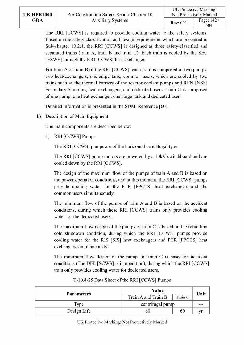
UK HPR1000
GDA
Pre-Construction Safety Report Chapter 10 Auxiliary Systems
UK Protective Marking: Not Protectively Marked
Rev: 001 Page: 142 /
504
UK Protective Marking: Not Protectively Marked
The RRI [CCWS] is required to provide cooling water to the safety systems. Based on the safety classification and design requirements which are presented in Sub-chapter 10.2.4, the RRI [CCWS] is designed as three safety-classified and separated trains (train A, train B and train C). Each train is cooled by the SEC [ESWS] through the RRI [CCWS] heat exchanger.
For train A or train B of the RRI [CCWS], each train is composed of two pumps, two heat-exchangers, one surge tank, common users, which are cooled by two trains such as the thermal barriers of the reactor coolant pumps and REN [NSS] Secondary Sampling heat exchangers, and dedicated users. Train C is composed of one pump, one heat exchanger, one surge tank and dedicated users.
Detailed information is presented in the SDM, Reference [60].
b) Description of Main Equipment
The main components are described below:
1) RRI [CCWS] Pumps
The RRI [CCWS] pumps are of the horizontal centrifugal type.
The RRI [CCWS] pump motors are powered by a 10kV switchboard and are cooled down by the RRI [CCWS].
The design of the maximum flow of the pumps of train A and B is based on the power operation conditions, and at this moment, the RRI [CCWS] pumps provide cooling water for the PTR [FPCTS] heat exchangers and the common users simultaneously.
The minimum flow of the pumps of train A and B is based on the accident conditions, during which these RRI [CCWS] trains only provides cooling water for the dedicated users.
The maximum flow design of the pumps of train C is based on the refuelling cold shutdown condition, during which the RRI [CCWS] pumps provide cooling water for the RIS [SIS] heat exchangers and PTR [FPCTS] heat exchangers simultaneously.
The minimum flow design of the pumps of train C is based on accident conditions (The DEL [SCWS] is in operation), during which the RRI [CCWS] train only provides cooling water for dedicated users.
T-10.4-25 Data Sheet of the RRI [CCWS] Pumps
Parameters Value
Unit Train A and Train B Train C
Type centrifugal pump ---
Design Life 60 60 yr.
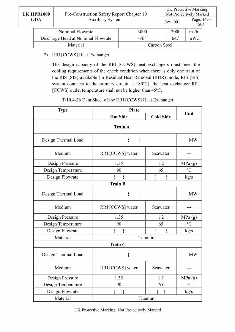
UK HPR1000
GDA
Pre-Construction Safety Report Chapter 10 Auxiliary Systems
UK Protective Marking: Not Protectively Marked
Rev: 001 Page: 143 /
504
UK Protective Marking: Not Protectively Marked
Nominal Flowrate 3000 2000 m3/h
Discharge Head at Nominal Flowrate 64+4 0
64+4 0 mWc
Material Carbon Steel
2) RRI [CCWS] Heat Exchanger
The design capacity of the RRI [CCWS] heat exchangers must meet the cooling requirements of the check condition when there is only one train of the RIS [SIS] available (in Residual Heat Removal (RHR) mode, RIS [SIS] system connects to the primary circuit at 180ºC); the heat exchanger RRI [CCWS] outlet temperature shall not be higher than 45ºC.
T-10.4-26 Data Sheet of the RRI [CCWS] Heat Exchanger
Type Plate Unit
Hot Side Cold Side
Train A
Design Thermal Load {****} MW
Medium RRI [CCWS] water Seawater ---
Design Pressure 1.35 1.2 MPa (g)
Design Temperature 90 65 °C
Design Flowrate {***} {****} kg/s
Train B
Design Thermal Load {****} MW
Medium RRI [CCWS] water Seawater ---
Design Pressure 1.35 1.2 MPa (g)
Design Temperature 90 65 °C
Design Flowrate {***} {****} kg/s
Material Titanium
Train C
Design Thermal Load {****} MW
Medium RRI [CCWS] water Seawater ---
Design Pressure 1.35 1.2 MPa (g)
Design Temperature 90 65 °C
Design Flowrate {***} {**} kg/s
Material Titanium
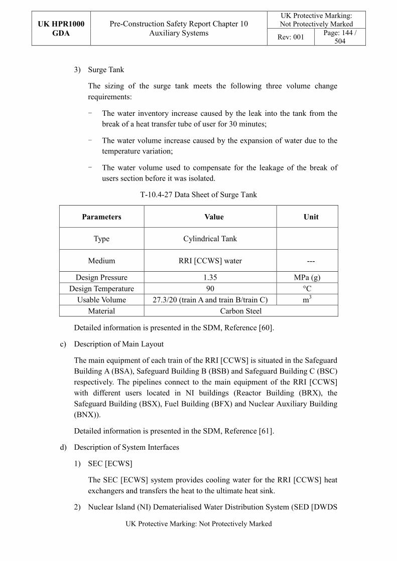
UK HPR1000
GDA
Pre-Construction Safety Report Chapter 10 Auxiliary Systems
UK Protective Marking: Not Protectively Marked
Rev: 001 Page: 144 /
504
UK Protective Marking: Not Protectively Marked
3) Surge Tank
The sizing of the surge tank meets the following three volume change requirements:
- The water inventory increase caused by the leak into the tank from the break of a heat transfer tube of user for 30 minutes;
- The water volume increase caused by the expansion of water due to the temperature variation;
- The water volume used to compensate for the leakage of the break of users section before it was isolated.
T-10.4-27 Data Sheet of Surge Tank
Parameters Value Unit
Type Cylindrical Tank
Medium RRI [CCWS] water ---
Design Pressure 1.35 MPa (g)
Design Temperature 90 °C
Usable Volume 27.3/20 (train A and train B/train C) m3
Material Carbon Steel
Detailed information is presented in the SDM, Reference [60].
c) Description of Main Layout
The main equipment of each train of the RRI [CCWS] is situated in the Safeguard Building A (BSA), Safeguard Building B (BSB) and Safeguard Building C (BSC) respectively. The pipelines connect to the main equipment of the RRI [CCWS] with different users located in NI buildings (Reactor Building (BRX), the Safeguard Building (BSX), Fuel Building (BFX) and Nuclear Auxiliary Building (BNX)).
Detailed information is presented in the SDM, Reference [61].
d) Description of System Interfaces
1) SEC [ECWS]
The SEC [ECWS] system provides cooling water for the RRI [CCWS] heat exchangers and transfers the heat to the ultimate heat sink.
2) Nuclear Island (NI) Dematerialised Water Distribution System (SED [DWDS
UK HPR1000
GDA
Pre-Construction Safety Report Chapter 10 Auxiliary Systems
UK Protective Marking: Not Protectively Marked
Rev: 001 Page: 145 /
504
UK Protective Marking: Not Protectively Marked
(NI)])
Every surge tank of the RRI [CCWS] system is provided with SED [DWDS (NI)] water charging lines.
3) Plant Radiation Monitoring System (KRT [PRMS])
The radioactive level of the RRI [CCWS] system is monitored by the KRT [PRMS] at the downstream of the RRI [CCWS] pump of each train.
Detailed information is presented in the SDM, Reference [60].
e) Description of I&C
1) Providing Cooling Water to RIS [SIS] under Safety Injection Signal
During Safe Injection (SI), one RRI [CCWS] pump of pre-set train is required to start and the non-classified users which are located in BNX and BWX will be isolated.
2) Control Supply Water Temperature under SI Signal
During SI, the supply temperature will be controlled between 15°C to 45°C by the control valves on the downstream pipeline and bypass pipeline of heat exchangers. When the temperature exceeds 35°C, the control valve on downstream pipeline is totally opened and the control valve on the bypass pipeline is totally closed. When the temperature is below 18°C, the control valve on bypass pipeline is totally opened and the control valve on downstream pipeline is totally closed.
3) Containment Isolation in Phase A
Under the signal of containment isolation phase A, the containment isolation valves on the pipelines to the Containment Cooling and Ventilation System (EVR [CCVS]) and RPE [VDS] are closed.
4) Containment Isolation in Phase B
Under the signal of containment isolation phase B, the containment isolation valves on the pipelines to the letdown heat exchanger will be closed.
5) Start-up Standby Pump Automatically in Train A or Train B
The standby pump will start up automatically when the operating pump in train A or train B fails, except the LOOP and SI conditions.
6) Switchover for Supply Pipelines of reactor coolant pump
Train A or train B of the RRI [CCWS] provides cooling water to motors, bearings and thermal barriers of the reactor coolant pumps. All three reactor coolant pumps are supplied by the same RRI [CCWS] train.
UK HPR1000
GDA
Pre-Construction Safety Report Chapter 10 Auxiliary Systems
UK Protective Marking: Not Protectively Marked
Rev: 001 Page: 146 /
504
UK Protective Marking: Not Protectively Marked
Following the signal of loss of the train supplying the reactor coolant pumps, which is not caused by the break of motors, bearings and thermal barriers of reactor coolant pumps, the corresponding isolation valves will open or close to switch the supplying pipeline to the other train.
Detailed information is presented in the SDM, Reference [62].
10.4.8.4.2 System Operation
a) Plant Normal Conditions
1) Reactor power operation
During reactor power operation conditions, two trains of the RRI [CCWS] operate.
Under this condition, the RRI [CCWS] provides cooling water for the following equipment:
- RRI [CCWS] pump motors;
- RIS [SIS] pump motors;
- PTR [FPCTS] heat exchangers;
- RCV [CVCS] heat exchanger and RCV [CVCS] pump motors;
- RCP [RCS] pumps (motors, bearings and thermal barriers);
- REN [NSS] heat exchangers;
- EVR [CCVS] containment ventilation cooling coils;
- RPE [VDS] heat exchangers;
- Coolant Storage and Treatment System (TEP [CSTS]) coolers;
- Operational Chilled Water System (DER [OCWS]) water chillers;
- Safety Chilled Water System (DEL [SCWS]) chillers;
- Reactor Boron and Water Makeup System (REA [RBWMS]) heat exchangers.
2) Hot shutdown (coolant temperature no less than140°C)
When the coolant temperature is no less than 140°C, requirements for the RRI [CCWS] are as follows:
- One pump and one heat exchanger of train A operate.
- One pump and one heat exchanger of train B operate.
- Train C remains on standby.
UK HPR1000
GDA
Pre-Construction Safety Report Chapter 10 Auxiliary Systems
UK Protective Marking: Not Protectively Marked
Rev: 001 Page: 147 /
504
UK Protective Marking: Not Protectively Marked
- Other pumps and heat exchangers are on standby.
3) Cold shutdown (coolant temperature: 140°C~100°C)
During Residual Heat Removal (RHR) mode, when the coolant temperature is between 140°C and 100°C, requirements for the RRI [CCWS] are as follows:
- Two pumps and two heat exchangers of train A operate.
- Two pumps and two heat exchangers of train B operate.
- Train C remains on standby.
4) Cold shutdown (coolant temperature: 100°C~60°C)
When the coolant temperature is between 100°C and 60°C with the RIS [SIS] connected, requirements for the RRI [CCWS] are as follows:
- Two pumps and two heat exchangers of train A operate.
- Two pumps and two heat exchangers of train B operate.
- Train C is in operation.
5) Cold shutdown (coolant temperature no more than 60°C)
When the coolant temperature is no more than 60°C, requirements for the RRI [CCWS] change with users’ requirements.
6) Switchover
Pumps and heat exchangers in the same train (only train A and train B) switch over periodically to balance service life.
Switchover of pumps and heat exchangers for the RRI [CCWS] leads to start-up of the corresponding SEC [ESWS] pumps.
b) Plant Accident Conditions
The RRI [CCWS] operates under all the DBC-2/3/4 conditions. Under some DEC, if the RRI [CCWS] is available, it is also required to be put into operation.
1) Loss of Offsite Power (LOOP)
During LOOP accident conditions, every RRI [CCWS] pump is powered by the EDGs, and all three trains of the RRI [CCWS] are available. Only one pump operates in each train at the same time.
2) Loss of Coolant Accident (LOCA)
The standby train starts up one pump while receiving the SI signal.
UK HPR1000
GDA
Pre-Construction Safety Report Chapter 10 Auxiliary Systems
UK Protective Marking: Not Protectively Marked
Rev: 001 Page: 148 /
504
UK Protective Marking: Not Protectively Marked
The users which are located in the Nuclear Auxiliary Building (BNX) and Radioactive Waste Treatment Building (BWX) are isolated from the RRI [CCWS] while receiving the SI signal.
The users EVR [CCVS] and RPE [VDS] are isolated from the RRI [CCWS] while receiving the containment isolation signal (stage 1).
The user RCV [CVCS] let down heat exchanger is isolated from the RRI [CCWS] while receiving the containment isolation signal (stage 2).
3) The RIS [SIS] Connected while Coolant temperature is at 180°C
During DBC 3-4 condition, the RIS [SIS] has to connect to the primary loop while the coolant temperature is at 180°C. Each train will put one pump and one heat exchanger of the RRI [CCWS] into operation to cool the RIS [SIS] heat exchanger under this condition. The other users (Operational Chilled Water System (DER [OCWS]), DEL [SCWS], TEP [CSTS], Reactor Boron and Water Makeup System (REA [RBWMS]), Liquid Waste Treatment System (TEU [LWTS]), EVR [CCVS] and RPE [VDS]) are isolated.
4) DEC Accident Condition
During some DEC conditions, once the RRI [CCWS] is available it supplies cooling water for users such as the EHR [CHRS] heat exchangers and pumps, the RIS [SIS] heat exchangers and pumps, and the PTR [FPCTS] heat exchangers.
Detailed information is presented in SDM, Reference [62].
10.4.8.5 Preliminary Design Substantiation
In this section, the system design is demonstrated to satisfy the safety functional requirements presented in Sub-chapter 10.4.8.1 and the general design requirements stated in Sub-chapter 10.2.4. Review of consistency of the system design against the newly developed principles is undertaken currently.
10.4.8.5.1 Compliance with Safety Functional Requirements
The system configuration and the capability of the components are compliant with the safety functional requirements. Detailed information of the system design is presented in the SDM, References [59], [60] and [62]. Furthermore, design substantiation of the RRI [CCWS] has been estimated in the fault study in Chapters 12 and 13.
a) Control of reactivity
The RRI [CCWS] is not required to perform this safety function.
b) Removal of Heat
The RRI [CCWS] is not required to perform this safety function.
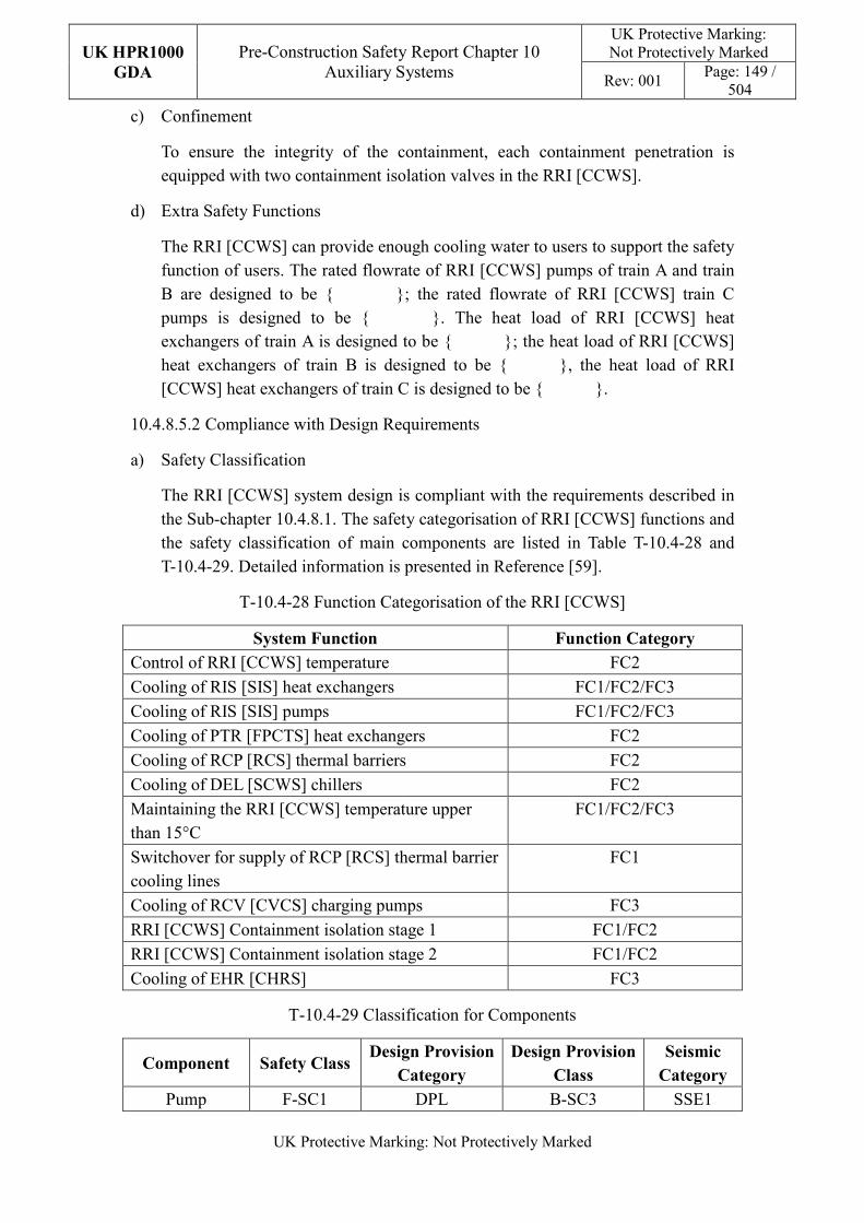
UK HPR1000
GDA
Pre-Construction Safety Report Chapter 10 Auxiliary Systems
UK Protective Marking: Not Protectively Marked
Rev: 001 Page: 149 /
504
UK Protective Marking: Not Protectively Marked
c) Confinement
To ensure the integrity of the containment, each containment penetration is equipped with two containment isolation valves in the RRI [CCWS].
d) Extra Safety Functions
The RRI [CCWS] can provide enough cooling water to users to support the safety function of users. The rated flowrate of RRI [CCWS] pumps of train A and train B are designed to be {******/*}; the rated flowrate of RRI [CCWS] train C pumps is designed to be {******/*}. The heat load of RRI [CCWS] heat exchangers of train A is designed to be {******}; the heat load of RRI [CCWS] heat exchangers of train B is designed to be {******}, the heat load of RRI [CCWS] heat exchangers of train C is designed to be {******}.
10.4.8.5.2 Compliance with Design Requirements
a) Safety Classification
The RRI [CCWS] system design is compliant with the requirements described in the Sub-chapter 10.4.8.1. The safety categorisation of RRI [CCWS] functions and the safety classification of main components are listed in Table T-10.4-28 and T-10.4-29. Detailed information is presented in Reference [59].
T-10.4-28 Function Categorisation of the RRI [CCWS]
System Function Function Category
Control of RRI [CCWS] temperature FC2
Cooling of RIS [SIS] heat exchangers FC1/FC2/FC3
Cooling of RIS [SIS] pumps FC1/FC2/FC3
Cooling of PTR [FPCTS] heat exchangers FC2
Cooling of RCP [RCS] thermal barriers FC2
Cooling of DEL [SCWS] chillers FC2
Maintaining the RRI [CCWS] temperature upper than 15°C
FC1/FC2/FC3
Switchover for supply of RCP [RCS] thermal barrier cooling lines
FC1
Cooling of RCV [CVCS] charging pumps FC3
RRI [CCWS] Containment isolation stage 1 FC1/FC2
RRI [CCWS] Containment isolation stage 2 FC1/FC2
Cooling of EHR [CHRS] FC3
T-10.4-29 Classification for Components
Component Safety Class Design Provision
Category
Design Provision
Class
Seismic
Category
Pump F-SC1 DPL B-SC3 SSE1
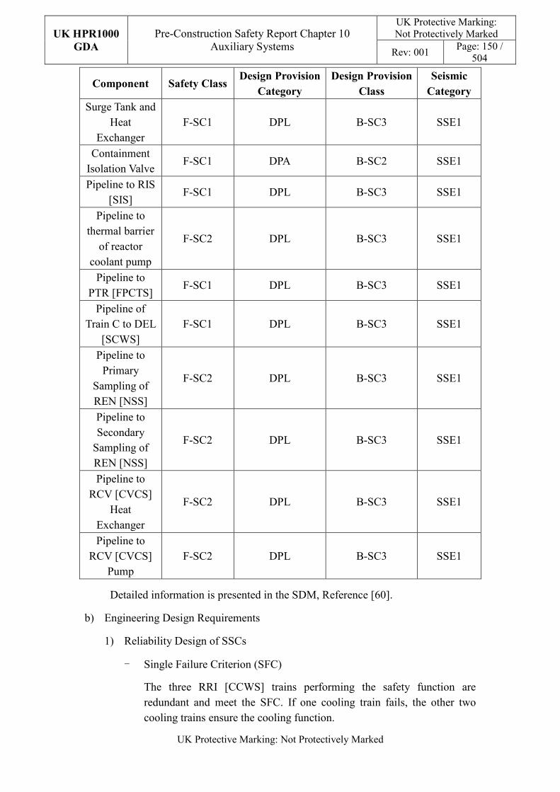
UK HPR1000
GDA
Pre-Construction Safety Report Chapter 10 Auxiliary Systems
UK Protective Marking: Not Protectively Marked
Rev: 001 Page: 150 /
504
UK Protective Marking: Not Protectively Marked
Component Safety Class Design Provision
Category
Design Provision
Class
Seismic
Category
Surge Tank and Heat
Exchanger F-SC1 DPL B-SC3 SSE1
Containment Isolation Valve
F-SC1 DPA B-SC2 SSE1
Pipeline to RIS [SIS]
F-SC1 DPL B-SC3 SSE1
Pipeline to thermal barrier
of reactor coolant pump
F-SC2 DPL B-SC3 SSE1
Pipeline to PTR [FPCTS]
F-SC1 DPL B-SC3 SSE1
Pipeline of Train C to DEL
[SCWS] F-SC1 DPL B-SC3 SSE1
Pipeline to Primary
Sampling of REN [NSS]
F-SC2 DPL B-SC3 SSE1
Pipeline to Secondary
Sampling of REN [NSS]
F-SC2 DPL B-SC3 SSE1
Pipeline to RCV [CVCS]
Heat Exchanger
F-SC2 DPL B-SC3 SSE1
Pipeline to RCV [CVCS]
Pump F-SC2 DPL B-SC3 SSE1
Detailed information is presented in the SDM, Reference [60].
b) Engineering Design Requirements
1) Reliability Design of SSCs
- Single Failure Criterion (SFC)
The three RRI [CCWS] trains performing the safety function are redundant and meet the SFC. If one cooling train fails, the other two cooling trains ensure the cooling function.
UK HPR1000
GDA
Pre-Construction Safety Report Chapter 10 Auxiliary Systems
UK Protective Marking: Not Protectively Marked
Rev: 001 Page: 151 /
504
UK Protective Marking: Not Protectively Marked
The redundant users are cooled by another RRI [CCWS] train when one train of the RRI [CCWS] trains fails.
The isolation of containment meets the single failure criterion with two redundant isolation valves.
Detailed information is presented in the SDM, Reference [59].
- Independence
The three RRI [CCWS] trains performing the safety function are independent. The parts mentioned above are located in different buildings physically isolated from each other for protection.
The three trains of the RRI [CCWS] are powered by different electrical safety trains.
Detailed information is presented in the SDM, Reference [59].
- Diversity
The containment isolation valves outside containment are equipped with SBO diesel generators, 24-hour batteries and mobile power supply devices. The isolation valves inside containment are equipped with SBO diesel generators and 2-hour batteries.
The break of heat exchangers can be detected by different signals (pressure, temperature, level, etc.).
- Fail-safe
The isolation valves of the RRI [CCWS] users in BNX and BWX are pneumatic valves which are closed when the air supply fails.
The fail-safe concept is considered in the RRI [CCWS] design process. The methodology and analysis of the fail-safe design in the RRI [CCWS] system is presented in the Reference [60]. After comprehensive analysis, other measures such as redundancy are used to improve safety in order to avoid the potential safety risks that may be introduced by “fail-safe” design on power plant.
- Ageing and Degradation
The management of equipment ageing and degradation follows the considerations stated in Sub-chapter 10.2.4.
The performance of equipment is guaranteed through life examination, inspection maintenance and testing, as well as monitoring during normal operation, which will ensure that ageing effects do not compromise safety performance.
UK HPR1000
GDA
Pre-Construction Safety Report Chapter 10 Auxiliary Systems
UK Protective Marking: Not Protectively Marked
Rev: 001 Page: 152 /
504
UK Protective Marking: Not Protectively Marked
2) Human Factors
The concept of human factors is taken into consideration in the system design. The system design of the RRI [CCWS] does not require short term operator intervention. There are operator actions during plant normal operation, of which the effect needs to be estimated.
Detailed design information about automatic control design of the system is presented in the SDM, Reference [62].
3) Autonomy
- Autonomy with respect to Operators
The design principles relevant to the autonomy with respect to operators are detailed in Sub-chapter 10.2.4. The design of the RRI [CCWS] fulfils these principles via control functional design; detailed information is presented in the SDM, Reference [60].
- Autonomy with respect to the Heat Sink
The design principles relevant to the autonomy with respect to the heat sink are applicable for RRI [CCWS] design. The RRI [CCWS] is cooled by SEC [ESWS] and the cooling water originates from sea water.
- Autonomy with respect to Power Supply Systems
The design of the RRI [CCWS] fulfils the principles relevant to the autonomy with respect to power supply systems. The three cooling trains are supplied by the EDGs. The containment isolation valves outside containment isolation valves are equipped with SBO diesel generators, 24-hour batteries and mobile power supply devices. The inside containment isolation valves are equipped with SBO diesel generators and 2-hour batteries.
4) Other Design Requirements
- Prevention of Harmful Interactions of Systems Important to Safety
The RRI [CCWS] system takes the following measures to prevent the harmful interactions of systems:
� Adequate isolation is provided (e.g. using double isolating valves) between the RRI [CCWS] and interfacing systems;
� The design pressure of the isolation valve between the RRI [CCWS] and the interfacing systems adopts the larger pressure of RRI [CCWS] and its interfacing systems;
� The RRI [CCWS] system is equipped with safety valves to prevent
UK HPR1000
GDA
Pre-Construction Safety Report Chapter 10 Auxiliary Systems
UK Protective Marking: Not Protectively Marked
Rev: 001 Page: 153 /
504
UK Protective Marking: Not Protectively Marked
the system from being damaged due to overpressure.
- Considerations Related to the Electrical Power Grid
Electrical power fluctuation has been considered in equipment design such as the capability of pumps to ensure the functions important to safety.
c) Equipment Qualification
All the RRI [CCWS] components required to perform the safety functions should be capable of operating under normal conditions and accident conditions, which requires the components to withstand the most adverse ambient environmental conditions expected.
Active components such as containment isolation valves, pumps and the valves are qualified.
All the RRI [CCWS] seismic classified components operate during and after the SSE. The components are seismically designed and qualified against the SSE load.
Principles of equipment qualification classification of the system are presented in Reference [59]. Detailed information related to the system equipment qualification is presented in Reference [60].
d) Protection against Internal and External Hazards
The RRI [CCWS] complies with the requirements stated in Sub-chapter 10.2.4, the RRI [CCWS] is required to be protected against several external and internal hazards, and the corresponding protection measures are described as below.
1) External hazards
- Earthquake
The seismic category for the components of the RRI [CCWS] performing Safety Category 1 (FC1) and Safety category 2 (FC2) safety functions is Seismic Category 1 (SSE1).
The seismic class for the components performing Safety category 3 (FC3) classified functions are Seismic Category 2 (SSE2) and NC respectively, based on their different user characteristics; the components with seismic class of NC are nuclear auxiliary building users and they can carry out isolation via the automatic isolation signals when leaks or breaks occur after the earthquake.
- Other External Hazards
The plant elevation and drainage facility are considered regarding
UK HPR1000
GDA
Pre-Construction Safety Report Chapter 10 Auxiliary Systems
UK Protective Marking: Not Protectively Marked
Rev: 001 Page: 154 /
504
UK Protective Marking: Not Protectively Marked
external flooding protection. The RRI [CCWS] protects against external hazards mainly through the building design. Specific protection design is presented in Reference [61].
2) Internal hazards
The three trains of RRI [CCWS] are located in different buildings for segregation, thus only one train will be damaged in case of internal explosion at the most, and thus CCF induced by internal hazards is eliminated or minimized. Specific protection design is presented in Reference [61].
e) Commissioning
Commissioning and tests are going to be carried out for the main RRI [CCWS] equipment to validation its functionality, such as pumps, exchangers, instruments and valves. The methodology for the system commissioning programme design is presented in Reference [31]. Further detailed site specific arrangements for the UK HPR1000 commissioning activities will be presented during the nuclear site licencing phase in conjunction with the site licensee.
f) Examination, Inspection, Maintenance and Testing
1) Examination and Inspection
There is no equipment of the RRI [CCWS] requiring in-service inspection.
2) Maintenance
During normal operating conditions, the RRI [CCWS] supplies cooling water to non-classified users in the NI. Thus, maintenance of standby pumps and heat exchangers can be performed during the power operation.
Maintenance of the other components can be performed during shutdown of plant.
3) Periodic Tests
Some equipment performing safety functions shall be subject to periodic testing, mainly including containment isolation valves and user isolation valves. A cooling flow test for the dedicated users will also be performed.
For the UK HPR1000, the periodic test design method is presented in the Reference [32].
g) Decommissioning
The design of the RRI [CCWS] considers decommissioning. A gradient is set in the pipeline layout to prevent the liquid accumulation and all equipment and pipes can be drained by draining lines.
UK HPR1000
GDA
Pre-Construction Safety Report Chapter 10 Auxiliary Systems
UK Protective Marking: Not Protectively Marked
Rev: 001 Page: 155 /
504
UK Protective Marking: Not Protectively Marked
h) Material Selection
The RRI [CCWS] side uses mostly carbon steel, except for the RRI [CCWS] heat exchangers which are made of titanium.
i) Special Thermal-hydraulic Phenomena
The design of the RRI [CCWS] considers the prevention of harmful thermal-hydraulic phenomena such as the hot water and cold water mixing.
j) Insulation
In order to reduce the heat dissipation from the pipelines to the environment, the pipelines of the RRI [CCWS] whose normal operating temperature is greater than or equal to 60°C are insulated. The insulation type is PP (personnel protection) and the insulation covers the cooling pipelines downstream RIS [SIS] heat exchangers and RCV [CVCS] heat exchangers.
10.4.8.6 Simplified Diagrams
The simplified system functional diagram is presented in Figures F-10.4-7, F-10.4-8 and F-10.4-9, detailed system functional diagram is in Reference [63].
10.4.9 Essential Service Water System (SEC [ESWS])
The SEC [ESWS] as a support system for the RRI [CCWS], which cools the RRI [CCWS] and as such contributes indirectly to safety functions of the RRI [CCWS]. The SEC [ESWS] consists of coarse rack, fine rack, gate, chlorination frame, SEC [ESWS] pump, flushing pump, sump pump, electrical heater, debris filter, motor of the travelling band screen, and the motor of the trash rake and flushing filter. The main components are located in the essential service water pumping station, SEC [ESWS] water intake gallery, SEC [ESWS] water drainage culvert and safeguard building. System information of the system is presented in the SDM, Reference [64].
10.4.9.1 Safety Functional Requirements
The requirements of the fundamental safety functions on the SEC [ESWS] design are described below.
10.4.9.1.1 Control of Reactivity
The SEC [ESWS] is not required to perform this safety function.
10.4.9.1.2 Removal of Heat
The SEC [ESWS] is providing cooling water to the RRI [CCWS] in normal operating conditions and accidental conditions.
10.4.9.1.3 Confinement
The SEC [ESWS] is ensuring the integrity of the Reactor Coolant Pressure Boundary
UK HPR1000
GDA
Pre-Construction Safety Report Chapter 10 Auxiliary Systems
UK Protective Marking: Not Protectively Marked
Rev: 001 Page: 156 /
504
UK Protective Marking: Not Protectively Marked
(RCPB) indirectly by cooling the thermal barriers of reactor coolant pumps via the RRI [CCWS].
10.4.9.1.4 Extra Safety Functions
The SEC [ESWS] is a support system for the RRI [CCWS], and the RRI [CCWS] is required to perform the removal of heat and confinement function, so the SEC [ESWS] is not required to perform any extra safety functions
10.4.9.2 Design Requirements
The general design requirements of the nuclear auxiliary systems which need to be considered are shown in Sub-chapter 10.2.4, among which the following requirements are not applicable for the SEC [ESWS]:
a) Prevention of Harmful Interactions of Systems Important to Safety
Not applicable, because there are no harmful interactions between SEC [ESWS] and other systems important to safety.
b) Insulation
Not applicable, because the SEC [ESWS] doesn’t have insulation design.
c) Considerations Related to the Electrical Power Grid
The functionality of equipment important to safety in the SEC [ESWS] is not compromised by disturbances in the electrical power grid.
d) Autonomy in Respect of Heat Sink
The SEC [ESWS] system is the heat sink for the unit and therefore is not required to consider loss of the heat sink.
The substantiation analysis of the SEC [ESWS] to other design requirements is shown in Sub-chapter 10.2.4.
10.4.9.3 Design Bases
This sub-chapter aims to provide the main design assumptions considered in the system design.
10.4.9.3.1 General Assumptions
a) Water intake
Water intake option for the SEC [ESWS] is offshore deeper water intake in GDA stage which needs to be confirmed in nuclear site licensing phasee.
b) Safety Classification
The SEC [ESWS] is providing cooling water to the RRI [CCWS] in normal
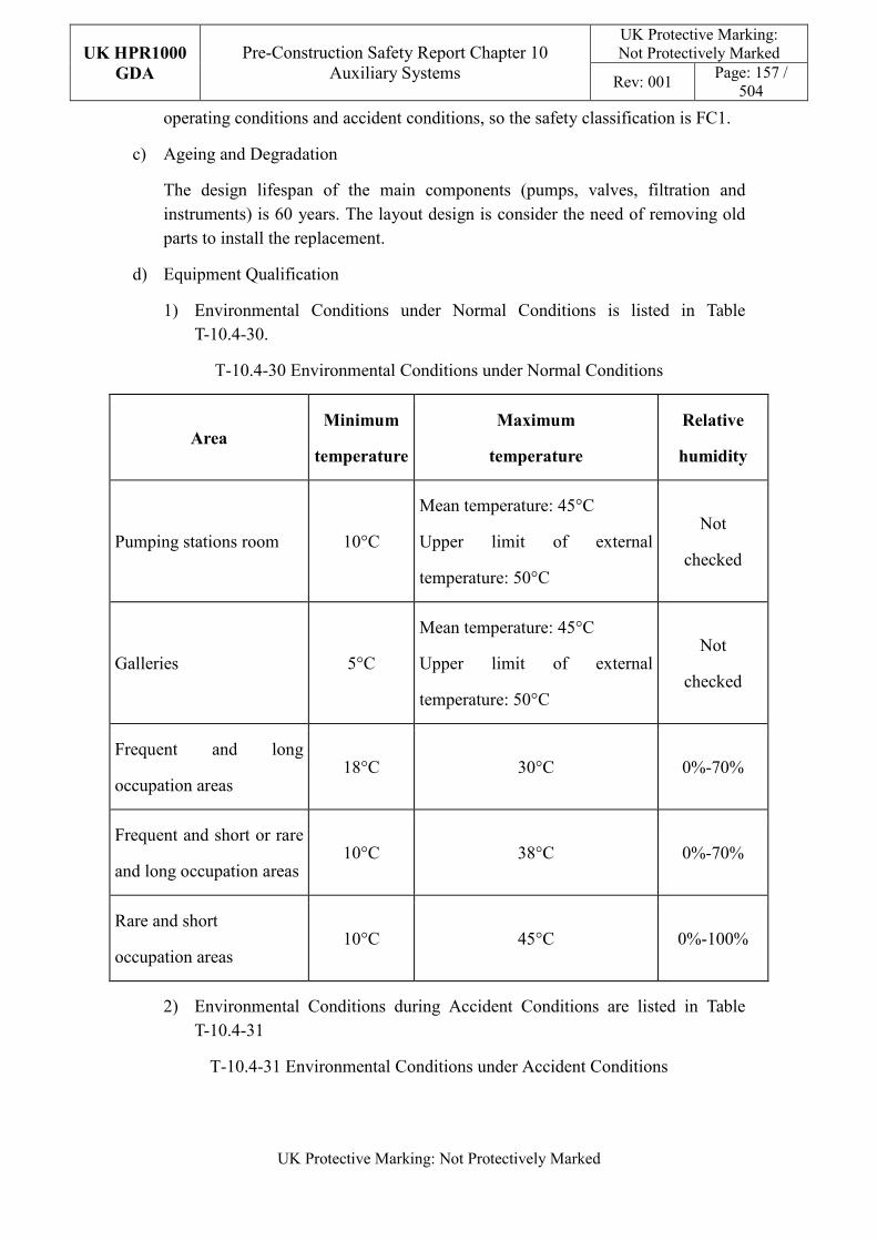
UK HPR1000
GDA
Pre-Construction Safety Report Chapter 10 Auxiliary Systems
UK Protective Marking: Not Protectively Marked
Rev: 001 Page: 157 /
504
UK Protective Marking: Not Protectively Marked
operating conditions and accident conditions, so the safety classification is FC1.
c) Ageing and Degradation
The design lifespan of the main components (pumps, valves, filtration and instruments) is 60 years. The layout design is consider the need of removing old parts to install the replacement.
d) Equipment Qualification
1) Environmental Conditions under Normal Conditions is listed in Table T-10.4-30.
T-10.4-30 Environmental Conditions under Normal Conditions
Area Minimum
temperature
Maximum
temperature
Relative
humidity
Pumping stations room 10°C
Mean temperature: 45°C
Upper limit of external
temperature: 50°C
Not
checked
Galleries 5°C
Mean temperature: 45°C
Upper limit of external
temperature: 50°C
Not
checked
Frequent and long
occupation areas 18°C 30°C 0%-70%
Frequent and short or rare
and long occupation areas 10°C 38°C 0%-70%
Rare and short
occupation areas 10°C 45°C 0%-100%
2) Environmental Conditions during Accident Conditions are listed in Table T-10.4-31
T-10.4-31 Environmental Conditions under Accident Conditions
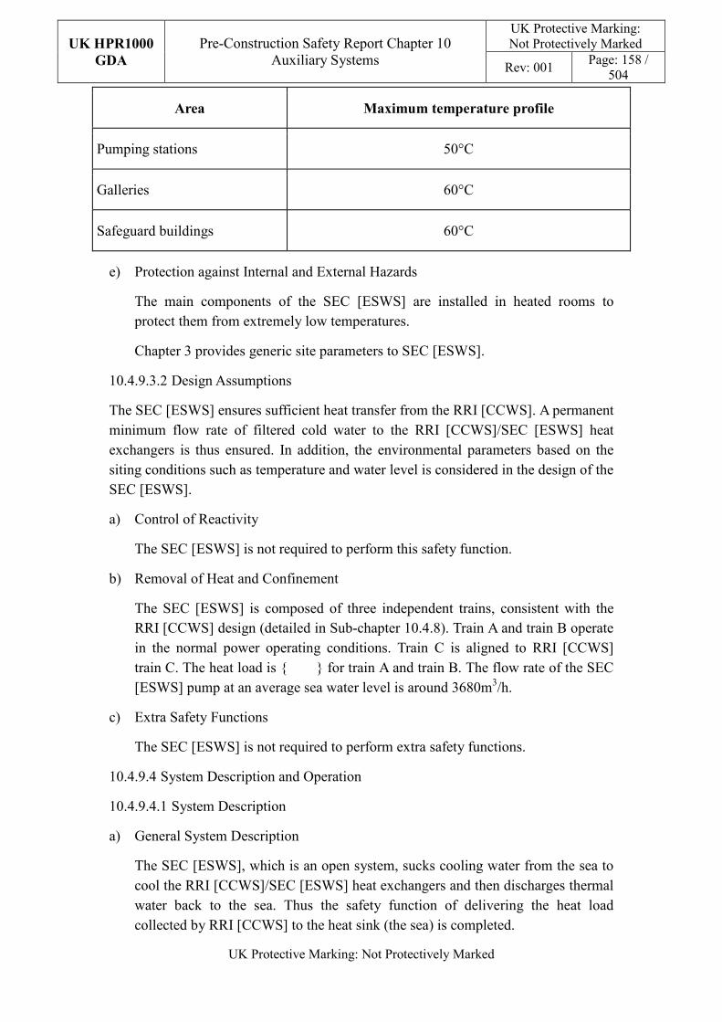
UK HPR1000
GDA
Pre-Construction Safety Report Chapter 10 Auxiliary Systems
UK Protective Marking: Not Protectively Marked
Rev: 001 Page: 158 /
504
UK Protective Marking: Not Protectively Marked
Area Maximum temperature profile
Pumping stations 50°C
Galleries 60°C
Safeguard buildings 60°C
e) Protection against Internal and External Hazards
The main components of the SEC [ESWS] are installed in heated rooms to protect them from extremely low temperatures.
Chapter 3 provides generic site parameters to SEC [ESWS].
10.4.9.3.2 Design Assumptions
The SEC [ESWS] ensures sufficient heat transfer from the RRI [CCWS]. A permanent minimum flow rate of filtered cold water to the RRI [CCWS]/SEC [ESWS] heat exchangers is thus ensured. In addition, the environmental parameters based on the siting conditions such as temperature and water level is considered in the design of the SEC [ESWS].
a) Control of Reactivity
The SEC [ESWS] is not required to perform this safety function.
b) Removal of Heat and Confinement
The SEC [ESWS] is composed of three independent trains, consistent with the RRI [CCWS] design (detailed in Sub-chapter 10.4.8). Train A and train B operate in the normal power operating conditions. Train C is aligned to RRI [CCWS] train C. The heat load is {****} for train A and train B. The flow rate of the SEC [ESWS] pump at an average sea water level is around 3680m3/h.
c) Extra Safety Functions
The SEC [ESWS] is not required to perform extra safety functions.
10.4.9.4 System Description and Operation
10.4.9.4.1 System Description
a) General System Description
The SEC [ESWS], which is an open system, sucks cooling water from the sea to cool the RRI [CCWS]/SEC [ESWS] heat exchangers and then discharges thermal water back to the sea. Thus the safety function of delivering the heat load collected by RRI [CCWS] to the heat sink (the sea) is completed.
UK HPR1000
GDA
Pre-Construction Safety Report Chapter 10 Auxiliary Systems
UK Protective Marking: Not Protectively Marked
Rev: 001 Page: 159 /
504
UK Protective Marking: Not Protectively Marked
The SEC [ESWS] is composed of three independent trains, consistent with the RRI [CCWS] design (detailed in Sub-chapter 10.4.8). Train A and train B operate in the normal power operating conditions, while train C is on standby. One pump is in service in each of train A and train B; Maintenance on the other pumps on standby in train A and train B can be performed once they are isolated.
Train A and train B have the same configuration. Each has two redundant sets of equipment, while train C only has one set. Each set includes the following equipment:
1) Seawater filtering equipment;
2) Suction pipeline;
3) Essential service water pump;
4) Debris filter;
5) Discharge pipeline;
6) Thermal water back flow pipeline;
7) Water discharge branch pipeline.
In each SEC [ESWS] train, seawater is sucked from the forebay through a dedicated SEC [ESWS] suction pipeline. After being filtered by a rotating type screen, the seawater is pumped by the essential service water pump through the SEC [ESWS] supply gallery and then into the RRI [CCWS]/SEC [ESWS] heat exchangers to cool the component cooling water. After passing through the RRI [CCWS]/SEC [ESWS] heat exchangers, the seawater is distributed to the overflow well via the SEC [ESWS] drainage pipe and is finally then returned to the sea through the discharge structure.
Detailed information is presented in the SDM, Reference [65].
The lowest temperature value for GDA generic site is different to that for Fangchenggang. Adding a thermal water back flow pipe from downstream of the RRI [CCWS] heat exchanger to upstream of the SEC [ESWS] pump is considered to be an effective option to guarantee the safety function of the cooling chain, Reference [66];
b) Description of Main Equipment
The main components are described as follows (detailed information is presented in the SDM, Reference [65]).
1) Seawater Filtering Equipment
The seawater filtering equipment consists of mainly the coarse rack, fine rack, travelling band screen and flushing system. These are installed in front of the essential service water pump for preliminary seawater filtering.
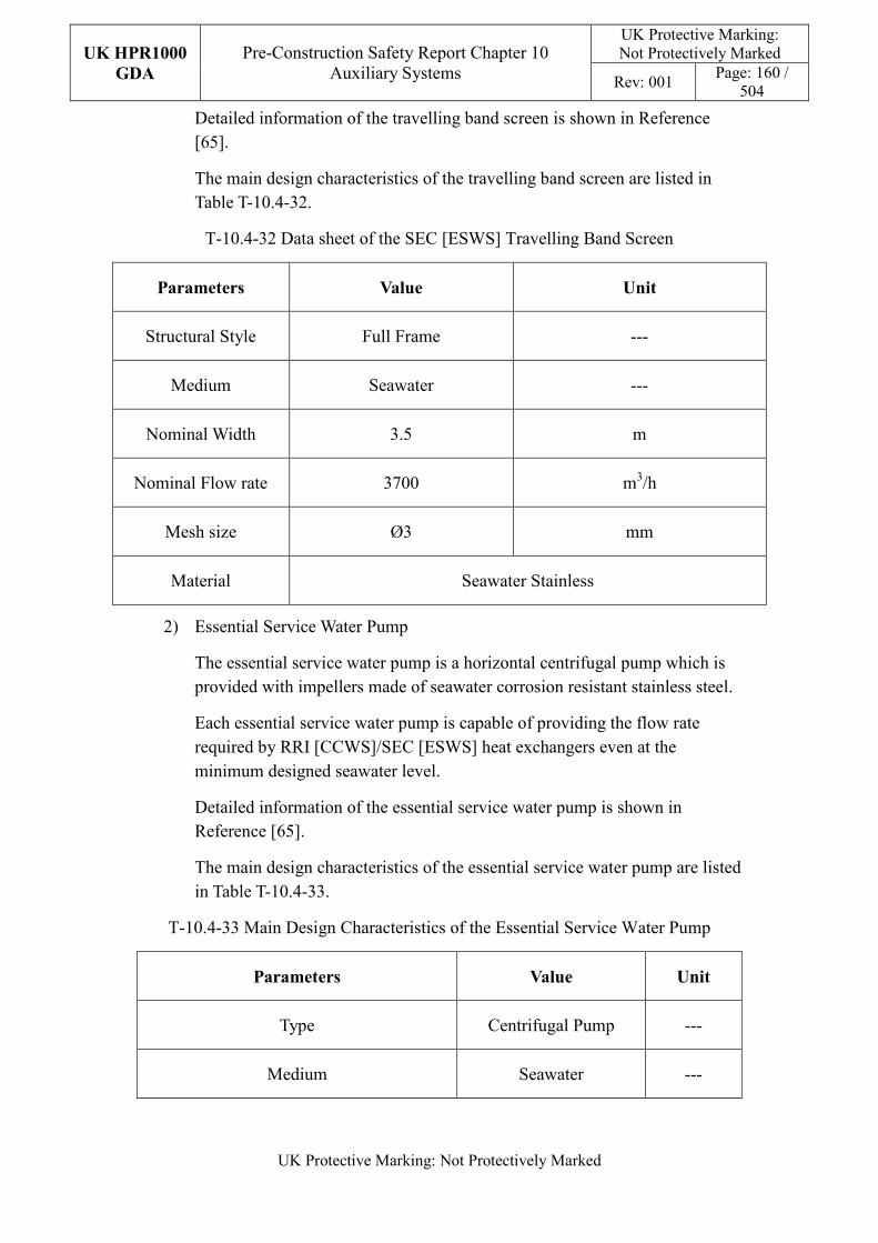
UK HPR1000
GDA
Pre-Construction Safety Report Chapter 10 Auxiliary Systems
UK Protective Marking: Not Protectively Marked
Rev: 001 Page: 160 /
504
UK Protective Marking: Not Protectively Marked
Detailed information of the travelling band screen is shown in Reference [65].
The main design characteristics of the travelling band screen are listed in Table T-10.4-32.
T-10.4-32 Data sheet of the SEC [ESWS] Travelling Band Screen
Parameters Value Unit
Structural Style Full Frame ---
Medium Seawater ---
Nominal Width 3.5 m
Nominal Flow rate 3700 m3/h
Mesh size Ø3 mm
Material Seawater Stainless
2) Essential Service Water Pump
The essential service water pump is a horizontal centrifugal pump which is provided with impellers made of seawater corrosion resistant stainless steel.
Each essential service water pump is capable of providing the flow rate required by RRI [CCWS]/SEC [ESWS] heat exchangers even at the minimum designed seawater level.
Detailed information of the essential service water pump is shown in Reference [65].
The main design characteristics of the essential service water pump are listed in Table T-10.4-33.
T-10.4-33 Main Design Characteristics of the Essential Service Water Pump
Parameters Value Unit
Type Centrifugal Pump ---
Medium Seawater ---
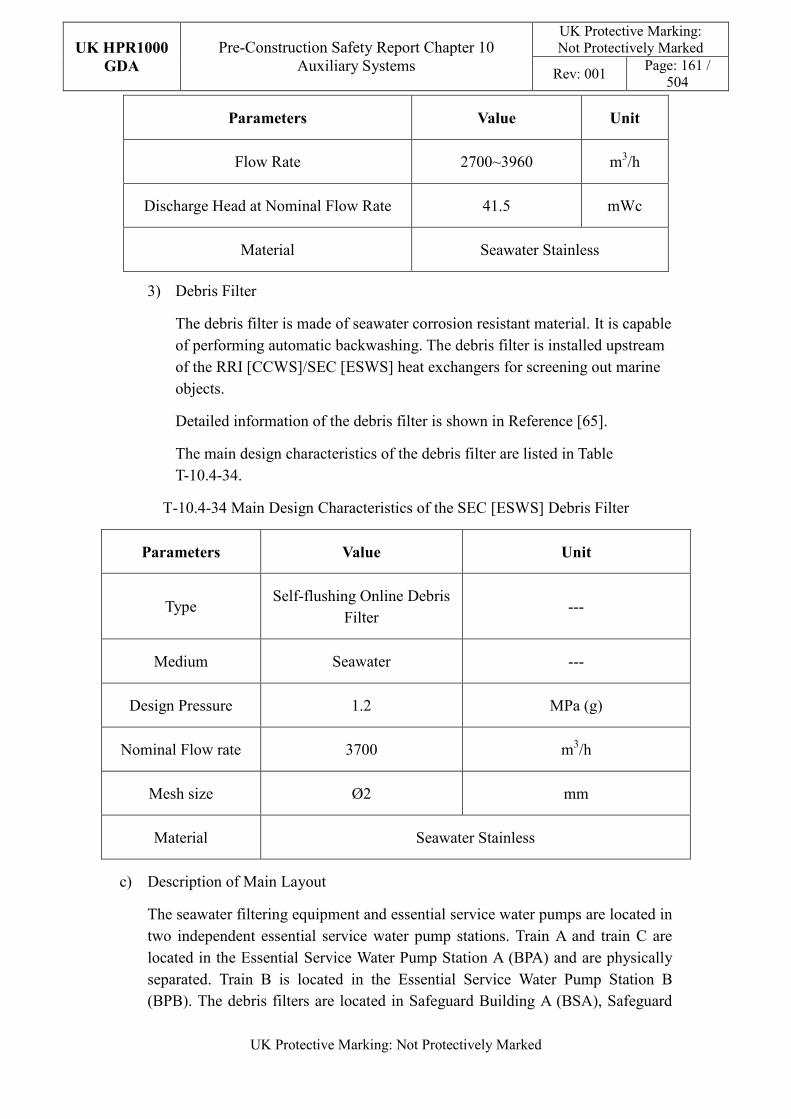
UK HPR1000
GDA
Pre-Construction Safety Report Chapter 10 Auxiliary Systems
UK Protective Marking: Not Protectively Marked
Rev: 001 Page: 161 /
504
UK Protective Marking: Not Protectively Marked
Parameters Value Unit
Flow Rate 2700~3960 m3/h
Discharge Head at Nominal Flow Rate 41.5 mWc
Material Seawater Stainless
3) Debris Filter
The debris filter is made of seawater corrosion resistant material. It is capable of performing automatic backwashing. The debris filter is installed upstream of the RRI [CCWS]/SEC [ESWS] heat exchangers for screening out marine objects.
Detailed information of the debris filter is shown in Reference [65].
The main design characteristics of the debris filter are listed in Table T-10.4-34.
T-10.4-34 Main Design Characteristics of the SEC [ESWS] Debris Filter
Parameters Value Unit
Type Self-flushing Online Debris
Filter ---
Medium Seawater ---
Design Pressure 1.2 MPa (g)
Nominal Flow rate 3700 m3/h
Mesh size Ø2 mm
Material Seawater Stainless
c) Description of Main Layout
The seawater filtering equipment and essential service water pumps are located in two independent essential service water pump stations. Train A and train C are located in the Essential Service Water Pump Station A (BPA) and are physically separated. Train B is located in the Essential Service Water Pump Station B (BPB). The debris filters are located in Safeguard Building A (BSA), Safeguard
UK HPR1000
GDA
Pre-Construction Safety Report Chapter 10 Auxiliary Systems
UK Protective Marking: Not Protectively Marked
Rev: 001 Page: 162 /
504
UK Protective Marking: Not Protectively Marked
Building B (BSB) and Safeguard Building C (BSC). The connecting pipes (including water intake pipeline and thermal water back flow pipeline) between pumps and RRI [CCWS]/SEC [ESWS] heat exchangers are installed in independent galleries.
Detailed information is presented in the SDM, Reference [67].
d) Description of System Interfaces
The mechanical systems supporting the fulfilment of SEC [ESWS] functions are:
1) Circulating Water Treatment System (CTE [CWTS])
The CTE [CWTS] performs the chlorination of the pre-filtrated seawater which supplies the essential service water pumps intake.
2) Potable Water System (SEP [PWS (NI)])
The SEP [PWS (NI)] performs:
— The first filling of the SEC [ESWS] circuit;
— The permanent flushing of the SEC [ESWS] cooling pumps shaft mechanical seals in normal operating conditions and in accident operating conditions as long as available.
3) Drain Systems
The SEC [ESWS] effluents are collected by:
— The Station Sewer System (SEO [SSS]) in the essential service water supply gallery and Safeguard Building (BSX);
— The SEC [ESWS] sumps and SEC [ESWS] sump pumps in BPA and BPB.
4) Essential Service Water Pumping Station Ventilation System (DXS [ESWVS])
The ventilation of the essential service water pump station and essential service water supply galleries is performed by the DXS [ESWVS].
5) Electrical Division of Safeguard Building Ventilation System (DVL [EDSBVS])
The ventilation of the rooms of the BSX with SEC [ESWS] debris filters installed inside is ensured by the DVL [EDSBVS].
6) Served Systems
The SEC [ESWS] ensures the cooling of the RRI [CCWS]. The RRI [CCWS] itself cools its users.
UK HPR1000
GDA
Pre-Construction Safety Report Chapter 10 Auxiliary Systems
UK Protective Marking: Not Protectively Marked
Rev: 001 Page: 163 /
504
UK Protective Marking: Not Protectively Marked
e) Description of Instrumentation and Control
The SEC [ESWS] is designed to be automatically controlled, remote controlled and continuously monitored.
The SEC [ESWS] is equipped with flow rate instrumentation to monitor the flow rate of cooling water during unit operation.
Both the inlet and outlet of the essential service water pump are equipped with pressure measurement instruments to protect pumps and monitor the circuits for abnormalities.
The SEC [ESWS] sump informs the operator of the working condition of the sump by the water level alarm in the main control room.
Detailed information is presented in the SDM, Reference [68].
10.4.9.4.2 System Operation
a) Plant Normal Condition
During normal operation of the power plant, the SEC [ESWS] operating configuration aligns with the RRI [CCWS] (see Sub-chapter 10.4.8).
b) Plant Accident Conditions
In the conditions of DBC-2/3/4 and in the condition of DEC-A, the SEC [ESWS] operating configurations aligns with the RRI [CCWS] if it is available (see Sub-chapter 10.4.8).
Detailed information is presented in the SDM, Reference [68].
10.4.9.5 Preliminary Design Substantiation
In this section, the system design is demonstrated to satisfy the safety functional requirements presented in Sub-chapter 10.4.9.1 and the general design requirements stated in Sub-chapter 10.2.4. Review of the consistency of the system design against the newly developed principles is currently being undertaken.
10.4.9.5.1 Compliance with Safety Functional Requirements
a) Control of Reactivity
The SEC [ESWS] is not required to perform this safety function.
b) Removal of Heat and Confinement
The flow rate of the SEC [ESWS] pump is 2700~3960m3/h, adapting to different sea water levels to meet the heat load removal requirements.
c) Extra Safety Functions
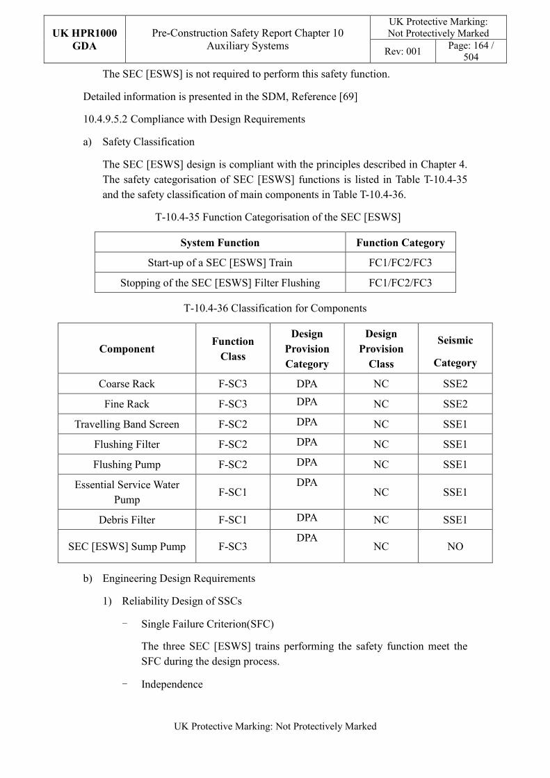
UK HPR1000
GDA
Pre-Construction Safety Report Chapter 10 Auxiliary Systems
UK Protective Marking: Not Protectively Marked
Rev: 001 Page: 164 /
504
UK Protective Marking: Not Protectively Marked
The SEC [ESWS] is not required to perform this safety function.
Detailed information is presented in the SDM, Reference [69]
10.4.9.5.2 Compliance with Design Requirements
a) Safety Classification
The SEC [ESWS] design is compliant with the principles described in Chapter 4. The safety categorisation of SEC [ESWS] functions is listed in Table T-10.4-35 and the safety classification of main components in Table T-10.4-36.
T-10.4-35 Function Categorisation of the SEC [ESWS]
System Function Function Category
Start-up of a SEC [ESWS] Train FC1/FC2/FC3
Stopping of the SEC [ESWS] Filter Flushing FC1/FC2/FC3
T-10.4-36 Classification for Components
Component Function
Class
Design
Provision
Category
Design
Provision
Class
Seismic
Category
Coarse Rack F-SC3 DPA NC SSE2
Fine Rack F-SC3 DPA NC SSE2
Travelling Band Screen F-SC2 DPA NC SSE1
Flushing Filter F-SC2 DPA NC SSE1
Flushing Pump F-SC2 DPA NC SSE1
Essential Service Water Pump
F-SC1 DPA
NC SSE1
Debris Filter F-SC1 DPA NC SSE1
SEC [ESWS] Sump Pump F-SC3 DPA
NC NO
b) Engineering Design Requirements
1) Reliability Design of SSCs
- Single Failure Criterion(SFC)
The three SEC [ESWS] trains performing the safety function meet the SFC during the design process.
- Independence
UK HPR1000
GDA
Pre-Construction Safety Report Chapter 10 Auxiliary Systems
UK Protective Marking: Not Protectively Marked
Rev: 001 Page: 165 /
504
UK Protective Marking: Not Protectively Marked
Each train of the SEC [ESWS] is arranged in a building or gallery physically isolated from the others for protection.
The three trains of the SEC [ESWS] are powered by different electrical safety trains.
- Diversity
The SEC [ESWS] is composed of three independent trains, consistent with the RRI [CCWS].
- Fail-safe
The analysis methodology is described in Reference [65]. The components of the SEC [ESWS] are designed in fail-safe position.
- Ageing and Degradation
The system is designed for the 60 year plant operation. The design lifespan of the main components (pumps, valves, filtrations, instruments) is 60 years. The layout design will consider the requirements of removing the old parts and installing replacements.
The SEC [ESWS] is composed of three independent trains which are not all in service at the same time. The out of service debris filter can be replaced.
2) Human Factors
Switchover between different SEC [ESWS] trains is automatic. Loss of one train can’t impact the operation of the other trains.
Each train of the SEC [ESWS] is arranged in a building or gallery physically isolated from the others and has enough space for maintenance and replacement of components.
3) Autonomy
- Autonomy in Respect of Operators
Switch-over between different SEC [ESWS] trains can be carried out automatically.
- Autonomy in Respect of Power Supply Systems
The main components of the SEC [ESWS] are at safe positions when loss of the power supply system occurs.
4) Other Design Requirements
The SEC [ESWS] is not required to consider other design requirements.
UK HPR1000
GDA
Pre-Construction Safety Report Chapter 10 Auxiliary Systems
UK Protective Marking: Not Protectively Marked
Rev: 001 Page: 166 /
504
UK Protective Marking: Not Protectively Marked
c) Equipment Qualification
All components performing safety functions shall operate in both normal conditions and accident conditions, which requires the components to withstand the most adverse ambient environments expected.
Each safety classified component, as shown in Table T-10.4-36 shall be qualified in accordance with the principles described in Chapter 4.
d) Protection against Internal and External Hazards
1) Internal Hazards
The SEC [ESWS] design ensures that the internal hazards of impacting train A or train B can only affect one train. Internal hazards impacting train C can only affect train C, which can be isolated entirely.
2) External Hazards
The plant elevation and drainage facility is considered regarding external flooding protection. The SEC [ESWS] protects against external hazards mainly through the building design. Specific protection design is presented in Reference [67].
e) Commissioning
Commissioning and tests shall be carried out for the main SEC [ESWS] equipment to validate its functionality, such as pumps, filters, instruments and valves. The methodology of the system commissioning programme design is presented in Reference [31]. Further detailed arrangements for the UK HPR1000 commissioning activities will be presented during the nuclear site licencing phase.
f) Examination, Inspection, Maintenance and Testing
1) Examination and Inspection
Pre-service examination and inspection is necessary:
— SEC [ESWS] pump: inspection of the function characters according to the periodic test programme of the pump, especially for the temperature and vibration of the shaft.
— Debris filter: inspection of the operating condition of the backwash valve and the pressure loss of the filter.
2) Maintenance
The SEC [ESWS] is designed to ensure sufficient cooling water flow to the RRI [CCWS]/ SEC [ESWS] heat exchanger during normal operation of the
UK HPR1000
GDA
Pre-Construction Safety Report Chapter 10 Auxiliary Systems
UK Protective Marking: Not Protectively Marked
Rev: 001 Page: 167 /
504
UK Protective Marking: Not Protectively Marked
plant to meet the safe operational requirements of the unit. The SEC [ESWS] is designed to allow for outages of FC1 and FC2 safety functions during shutdown to free up the train and equipment for maintenance.
The design and layout of other equipment is facilitated during maintenance of the plant during refuelling.
3) Periodic Tests
Some equipment performing safety function shall be subject to periodic testing, mainly including containment isolation valves and user isolation valves. The cooling flow test of the dedicated users will also be performed.
For the UK HPR1000, the periodic test design is under development, the periodic test design method is presented in the Reference [32].
g) Decommissioning
The design of the SEC [ESWS] considers the decommissioning. A gradient is set in the pipeline layout to prevent the liquid accumulation and all equipment and pipes can be drained by draining lines.
h) Material Selection
Materials of SEC components are chosen in order to withstand the effects induced by the seawater:
1) Pumps, swing and centre post guided check valves are made of stainless steel for resisting the effects of seawater;
2) Butterfly valves, filters are made of rubber-coated carbon steel.
i) Special Thermal-hydraulic Phenomena
The SEC [ESWS] is not required to consider special thermal-hydraulic phenomena
j) Insulation
The SEC [ESWS] is not required to consider insulation
10.4.9.6 Functional Diagrams
The simplified flow diagram of the SEC [ESWS] is shown in Figure F-10.4-10, detailed system functional diagram is in Reference [70].
10.4.10 ALARP Assessment
10.4.10.1 General Description
A preliminary ALARP analysis has been performed on the nuclear auxiliary systems. The analysis is consistent with the arguments stated in the Sub-claim 3.3.6.SC10.3 of
UK HPR1000
GDA
Pre-Construction Safety Report Chapter 10 Auxiliary Systems
UK Protective Marking: Not Protectively Marked
Rev: 001 Page: 168 /
504
UK Protective Marking: Not Protectively Marked
the route map presented in Appendix B:
Argument 3.3.6.SC10.3-1: The SSCs meet the requirements of the relevant design principles (generic and system specific) and therefore of relevant good practice;
The ALARP assessment is carried out following the ALARP methodology presented in Chapter 33, a specific ALARP demonstration report has been prepared, Reference [14].
10.4.10.2 Review of Design against RGP & OPEX
The RGP for SSCs design is identified, the suitable analysis against the applicable codes and standards identified for the SSCs design in ME area are carried out in the Reference [13]. The consistency analysis between the current design and the RGP is still under development to ensure that the design of the SSCs meets the requirements of the UK context.
The OPEX from multiple reactors has shown that the primary circuit zinc injection technology has the effect of reducing worker dose rate and reduces the corrosion of material in the primary circuit. The design modification of applying the technology in the UK HPR1000 system design is being carried out at the moment.
10.4.10.3 Insight from Risk Analysis
The risk analysis is being developed at this moment and a preliminary result was produced based on the current result, no insight was received for the design of nuclear auxiliary systems from the risk analysis currently. The analysis will keep being carried out as the GDA progresses.
10.4.10.4 Specific Review of Potential Improvements
At this stage, one gap is identified, the temperature range is difference between the Fangchenggang and GDA generic site. Cooling chain (RRI [CCWS] and SEC [ESWS]) cannot adopt in low sea water temperature. A thermal water back flow pipeline and discharge branch pipeline are added for each set of the SEC [ESWS]. Currently, this has become a design modification of the UK HPR1000. The optioneering has been carried out, analysis report has been produced and the system design manuals are modified. The optioneering is presented in details in Reference [66].
10.4.10.5 ALARP Demonstration
A compliance analysis of the system design with respect to the UK HPR1000 general safety engineering principles is made in the system section of each sub-chapter. The analysis shows that the design of the SSCs meets relevant requirements and no gaps have been identified. A systematic review will be carried out on the system design to ensure that no new gaps are identified between the newly developed requirements and the design. Any potential enhancements identified during this review will be taken
UK HPR1000
GDA
Pre-Construction Safety Report Chapter 10 Auxiliary Systems
UK Protective Marking: Not Protectively Marked
Rev: 001 Page: 169 /
504
UK Protective Marking: Not Protectively Marked
into account in the future design development.
In summary, the ALARP analysis and demonstration work is currently being carried out. A preliminary ALARP demonstration topic report to present the current analysis results as well as the arrangement for future ALARP analysis work is presented in Reference [14].
10.4.11 Concluding Remarks
This chapter provides an introduction on the design information of nuclear auxiliary systems in the UK HPR1000 nuclear power plant.
As various technical areas are currently under development, which may influence the current design, a systematic review will be carried out after the work has been finished. If any gap is identified during the technical review, an ALARP demonstration will be carried out and effort will be made to reduce the risk as low as reasonably practicable.
10.4.12 Simplified Diagrams
Simplified diagrams of nuclear auxiliary systems mentioned in Sub-chapters 10.4.3 to 10.4.9 are presented as follows:
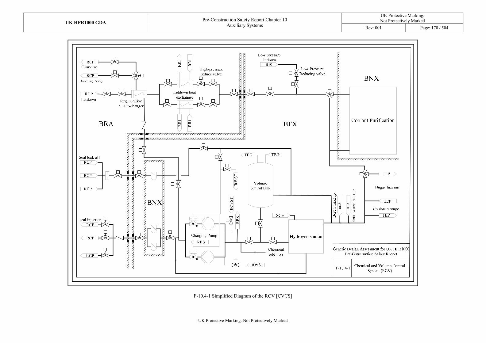
UK HPR1000 GDA Pre-Construction Safety Report Chapter 10
Auxiliary Systems
UK Protective Marking: Not Protectively Marked
Rev: 001 Page: 170 / 504
UK Protective Marking: Not Protectively Marked
F-10.4-1 Simplified Diagram of the RCV [CVCS]
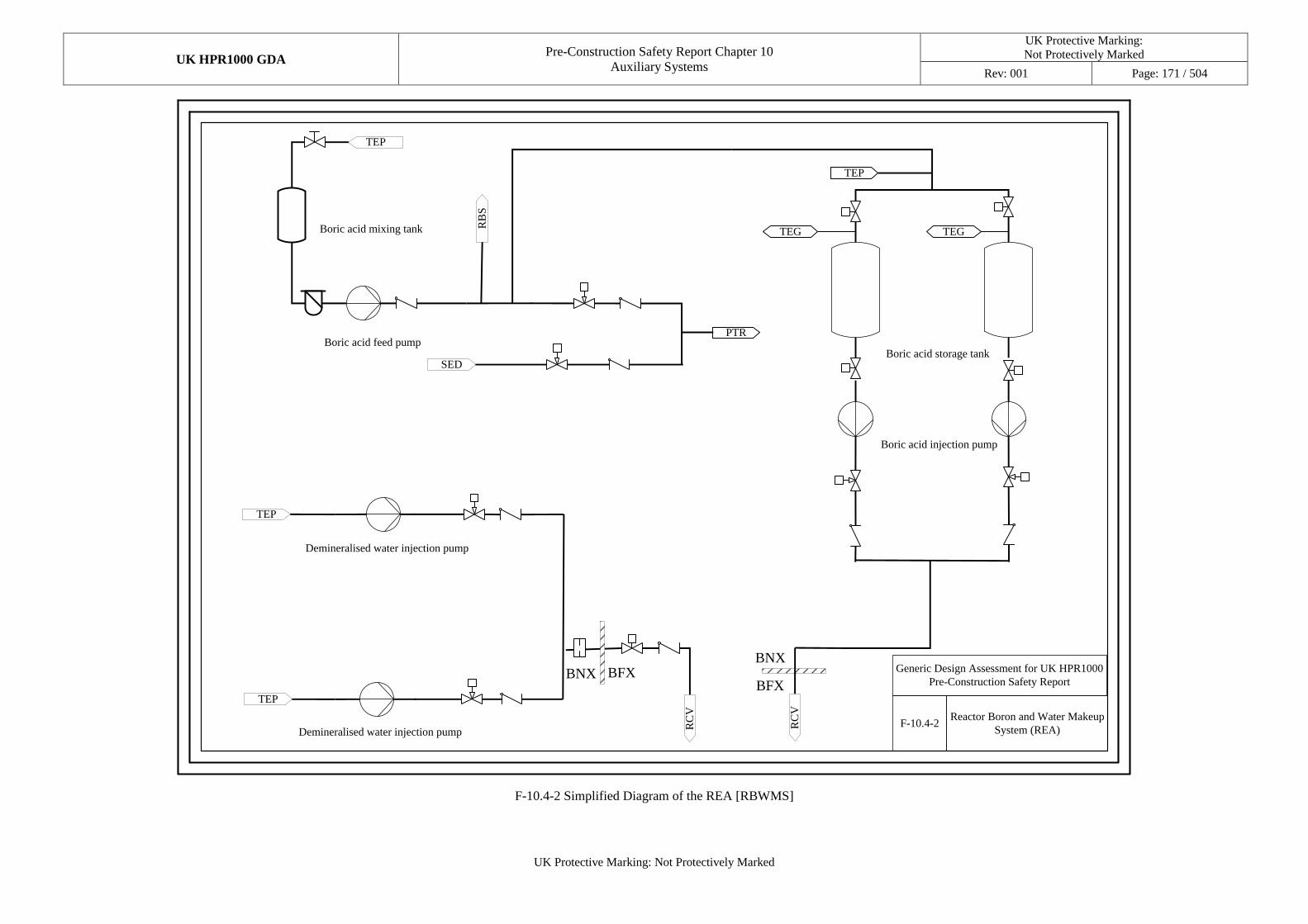
UK HPR1000 GDA Pre-Construction Safety Report Chapter 10
Auxiliary Systems
UK Protective Marking:
Not Protectively Marked
Rev: 001 Page: 171 / 504
UK Protective Marking: Not Protectively Marked
Boric acid feed pump
RB
S
Boric acid storage tank
Boric acid injection pump
Demineralised water injection pump
TEP
Demineralised water injection pump
TEP
SED
RC
V
Boric acid mixing tank
TEP
RC
V
BNX BFXBNX
BFX
Generic Design Assessment for UK HPR1000
Pre-Construction Safety Report
F-10.4-2Reactor Boron and Water Makeup
System (REA)
PTR
TEG TEG
TEP
F-10.4-2 Simplified Diagram of the REA [RBWMS]
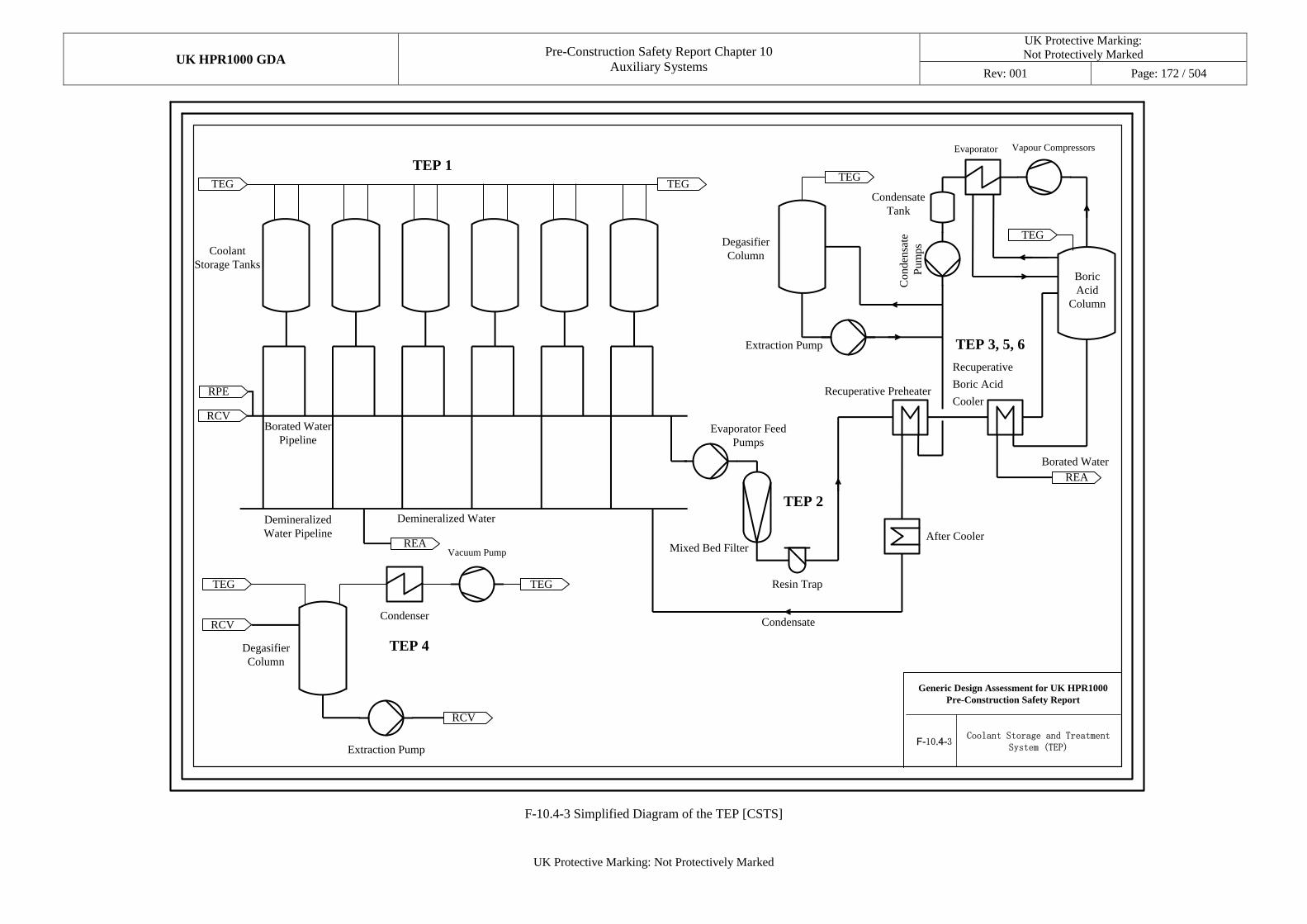
UK HPR1000 GDA Pre-Construction Safety Report Chapter 10
Auxiliary Systems
UK Protective Marking:
Not Protectively Marked
Rev: 001 Page: 172 / 504
UK Protective Marking: Not Protectively Marked
Coolant
Storage Tanks
TEG TEG
RCV
REA
Demineralized
Water Pipeline
Borated Water
PipelineEvaporator Feed
Pumps
Mixed Bed Filter
RCV
Degasifier
Column
TEG
F-10.4-3Coolant Storage and Treatment
System (TEP)
Demineralized Water
RPE
Condenser
TEG
RCV
Extraction Pump
TEP 1
TEP 4
Resin Trap
Vapour Compressors
TEG
REA
TEP 2
TEG
Condensate
TEP 3, 5, 6
Evaporator
Condensate
Tank
Borated Water
Vacuum Pump
Generic Design Assessment for UK HPR1000
Pre-Construction Safety Report
After Cooler
Recuperative Preheater
Recuperative
Boric Acid
Cooler
Extraction Pump
Degasifier
Column
Conden
sate
Pum
ps
Boric
Acid
Column
F-10.4-3 Simplified Diagram of the TEP [CSTS]
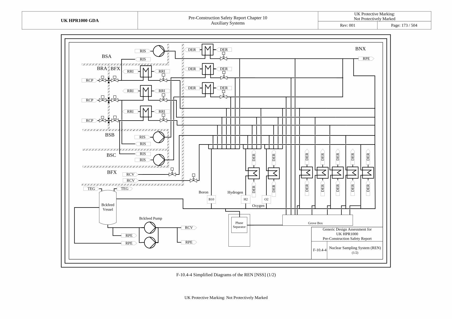
UK HPR1000 GDA Pre-Construction Safety Report Chapter 10
Auxiliary Systems
UK Protective Marking:
Not Protectively Marked
Rev: 001 Page: 173 / 504
UK Protective Marking: Not Protectively Marked
DE
RD
ER
DE
RD
ER
RCP
RRIRRI
RIS
RIS
RCP
RRIRRI
RCP
RRIRRI
RIS
RIS
RIS
RIS
DERDER
RCV
RCV
DERDER
DERDER
DE
RD
ER
RPE
H2 O2B10
Phase
Separator
TEGTEG
RCV
RPE
RPE
RPE
BSB
BRA
BSA
BSC
BFX
BNX
DE
RD
ER
DE
RD
ER
DE
RD
ER
DE
RD
ER
Bckfeed Pump
Grove Box
Boron Hydrogen
Oxygen
BFX
Bckfeed
Vessel
Generic Design Assessment for
UK HPR1000
Pre-Construction Safety Report
F-10.4-4Nuclear Sampling System (REN)
(1/2)
F-10.4-4 Simplified Diagrams of the REN [NSS] (1/2)
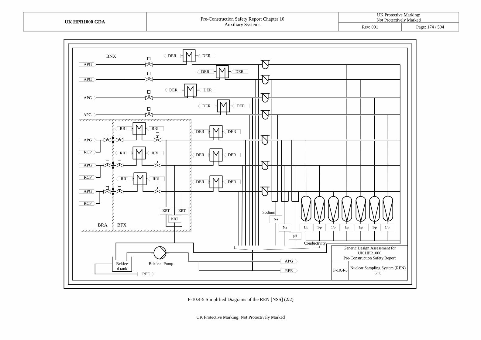
UK HPR1000 GDA Pre-Construction Safety Report Chapter 10
Auxiliary Systems
UK Protective Marking:
Not Protectively Marked
Rev: 001 Page: 174 / 504
UK Protective Marking: Not Protectively Marked
APG
APG
RCP
KRT
APG
RCP
APG
RCP
KRT KRT
Na
Na
pH
1/ρ1/ρ 1/ρ 1/ρ1/ρ 1/ρ 1/ρ
APG
RPERPE
RRIRRIDER DER
APG
APG
APG
DER DER
BRA BFX
BNX
DER DER
DER DER
DER DER
RRIRRI
RRIRRI
DER DER
DER DER
Bckfeed Pump
Sodium
Conductivity
Bckfee
d tank
Generic Design Assessment for
UK HPR1000
Pre-Construction Safety Report
F-10.4-5Nuclear Sampling System (REN)
(2/2)
F-10.4-5 Simplified Diagrams of the REN [NSS] (2/2)
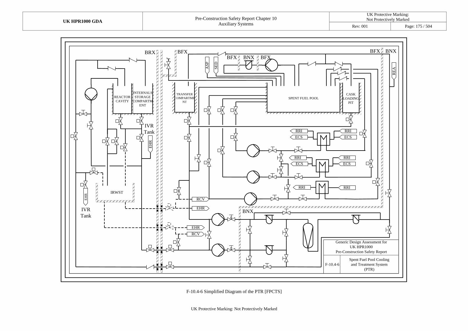
UK HPR1000 GDA Pre-Construction Safety Report Chapter 10
Auxiliary Systems
UK Protective Marking:
Not Protectively Marked
Rev: 001 Page: 175 / 504
UK Protective Marking: Not Protectively Marked
INTERNALS
STORAGE
COMPARTM
ENT
REACTOR
CAVITY
TRANSFER
COMPARTME
NT
CASK
LOADING
PIT
SPENT FUEL POOL
IRWST
RRI
ECS
RRI
ECS
RRI
ECS
RRI
ECS
RRIRRI
RE
ASE
D
EH
R
EH
R
BRX BFXBNX
F-10.4-6
Spent Fuel Pool Cooling
and Treatment System
(PTR)
BNX
BNXBFX
BFX BFX
AS
P
EHR
RCV
EHR
RCV
Generic Design Assessment for
UK HPR1000
Pre-Construction Safety Report
IVR
Tank
IVR
Tank
F-10.4-6 Simplified Diagram of the PTR [FPCTS]
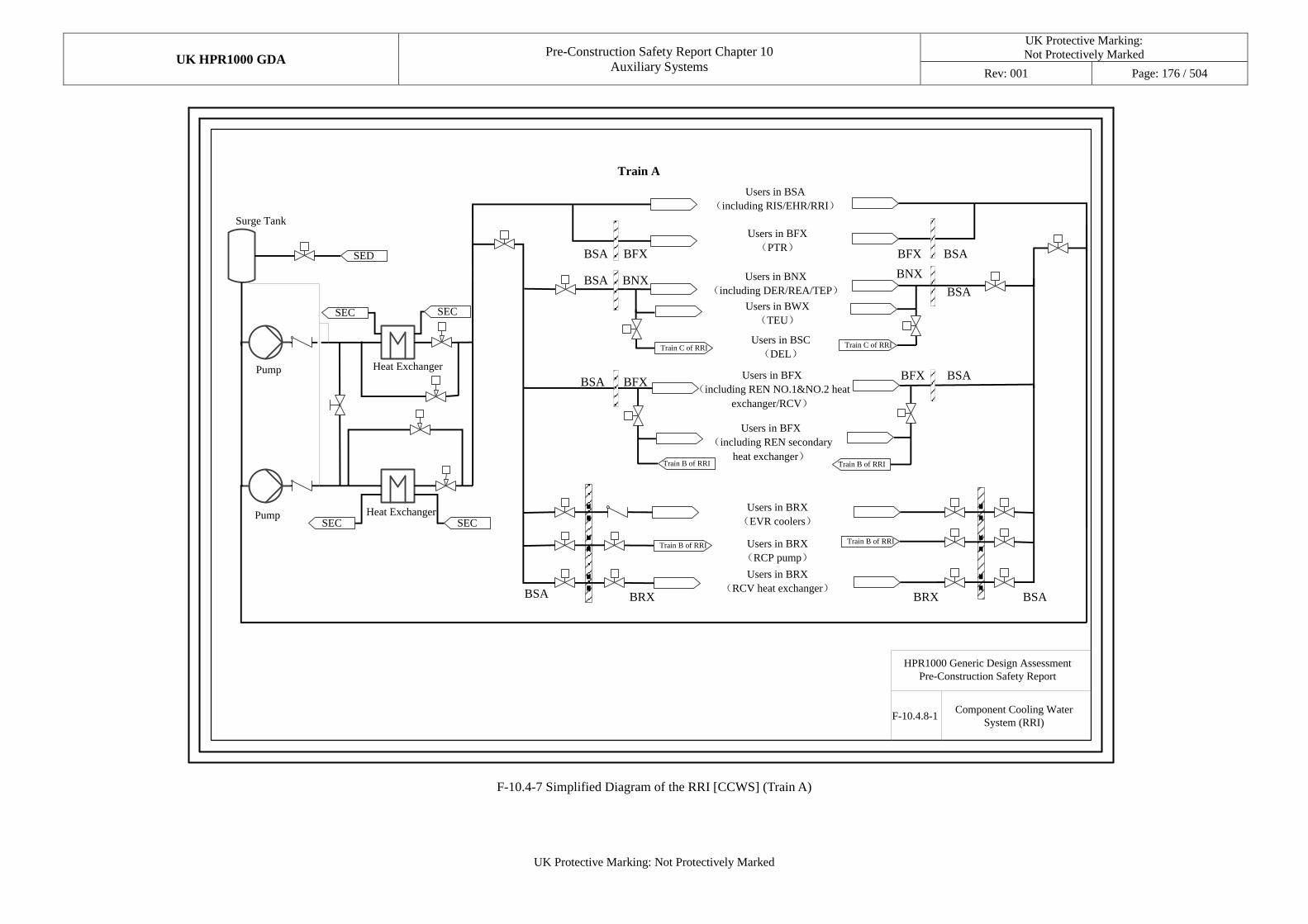
UK HPR1000 GDA Pre-Construction Safety Report Chapter 10
Auxiliary Systems
UK Protective Marking:
Not Protectively Marked
Rev: 001 Page: 176 / 504
UK Protective Marking: Not Protectively Marked
HPR1000 Generic Design Assessment
Pre-Construction Safety Report
Component Cooling Water
System (RRI)F-10.4.8-1
SED
SECSEC
SECSEC
Train A
BSA BFX BFX BSA
BSA BNX
BSA BFX
BNX
BSA
BFX BSA
BSA BRX BSABRX
Pump
Pump
Heat Exchanger
Surge Tank
Heat Exchanger
Users in BSA
(including RIS/EHR/RRI)
Users in BNX
(including DER/REA/TEP)
Users in BFX
(PTR)
Users in BFX
(including REN NO.1&NO.2 heat
exchanger/RCV)
Users in BRX
(RCP pump)
Users in BRX
(EVR coolers)
Users in BRX
(RCV heat exchanger)
Users in BWX
(TEU)
Users in BFX
(including REN secondary
heat exchanger)
Users in BSC
(DEL)
Train B of RRITrain B of RRI
Train B of RRI Train B of RRI
Train C of RRI Train C of RRI
F-10.4-7 Simplified Diagram of the RRI [CCWS] (Train A)
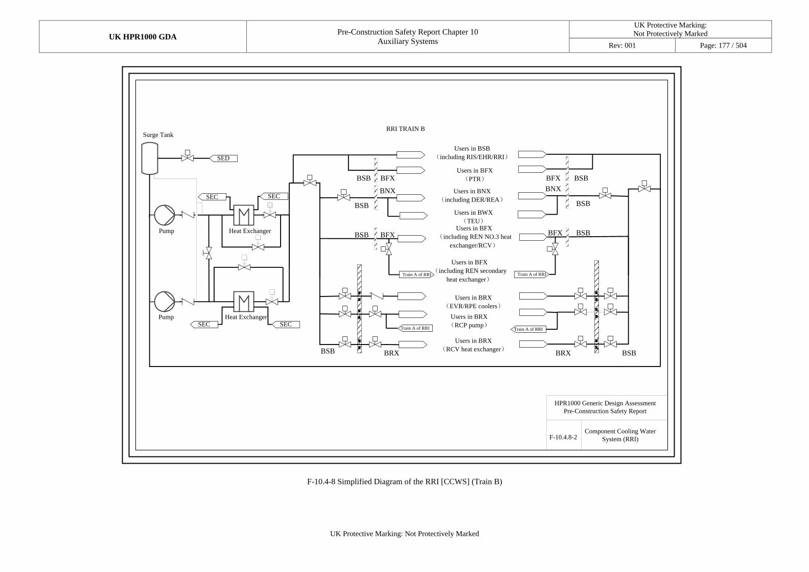
UK HPR1000 GDA Pre-Construction Safety Report Chapter 10
Auxiliary Systems
UK Protective Marking:
Not Protectively Marked
Rev: 001 Page: 177 / 504
UK Protective Marking: Not Protectively Marked
Component Cooling Water
System (RRI)
HPR1000 Generic Design Assessment
Pre-Construction Safety Report
F-10.4.8-2
SED
RRI TRAIN B
BSB BFX BFX BSB
BSB
BNX
BSB BFX
BNX
BSB
BFX BSB
BSB BRX BSBBRX
SECSEC
SECSEC
Users in BSB
(including RIS/EHR/RRI)
Users in BNX
(including DER/REA)
Users in BFX
(PTR)
Users in BRX
(RCP pump)
Users in BRX
(EVR/RPE coolers)
Users in BRX
(RCV heat exchanger)
Users in BWX
(TEU)Users in BFX
(including REN NO.3 heat
exchanger/RCV)
Users in BFX
(including REN secondary
heat exchanger)
Pump
Pump
Heat Exchanger
Surge Tank
Heat Exchanger
Train A of RRI Train A of RRI
Train A of RRI Train A of RRI
F-10.4-8 Simplified Diagram of the RRI [CCWS] (Train B)
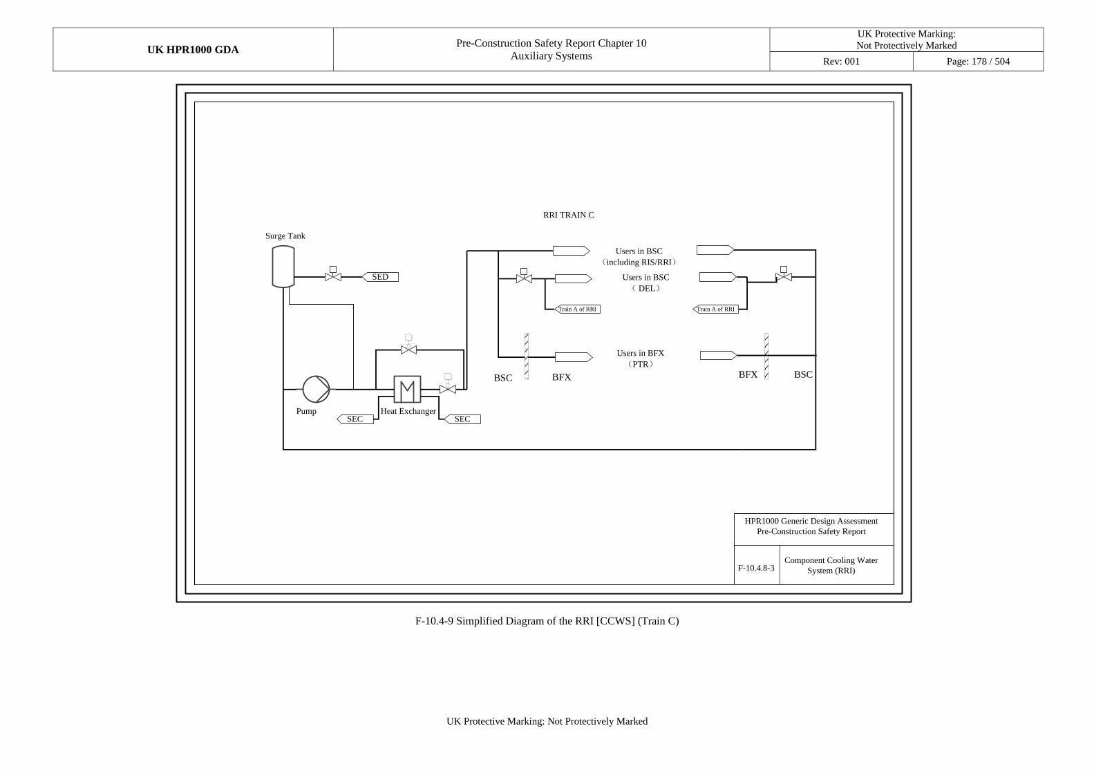
UK HPR1000 GDA Pre-Construction Safety Report Chapter 10
Auxiliary Systems
UK Protective Marking:
Not Protectively Marked
Rev: 001 Page: 178 / 504
UK Protective Marking: Not Protectively Marked
Component Cooling Water
System (RRI)
HPR1000 Generic Design Assessment
Pre-Construction Safety Report
F-10.4.8-3
SED
SECSEC
RRI TRAIN C
BFX BFXBSC BSC
Users in BSC
( DEL)
Users in BSC
(including RIS/RRI)
Users in BFX
(PTR)
Pump Heat Exchanger
Surge Tank
Train A of RRI Train A of RRI
F-10.4-9 Simplified Diagram of the RRI [CCWS] (Train C)
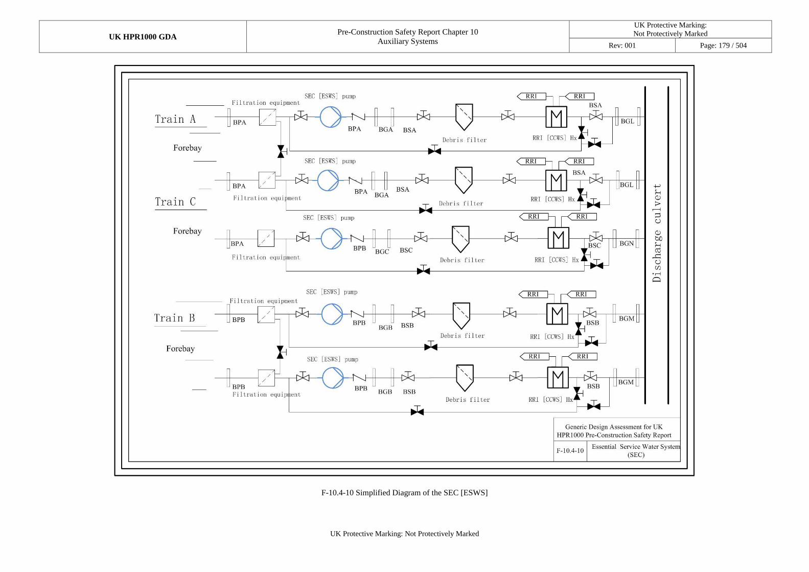
UK HPR1000 GDA Pre-Construction Safety Report Chapter 10
Auxiliary Systems
UK Protective Marking:
Not Protectively Marked
Rev: 001 Page: 179 / 504
UK Protective Marking: Not Protectively Marked
F-10.4-10 Simplified Diagram of the SEC [ESWS]
UK HPR1000
GDA
Pre-Construction Safety Report Chapter 10 Auxiliary Systems
UK Protective Marking: Not Protectively Marked
Rev: 001 Page: 180 /
504
UK Protective Marking: Not Protectively Marked
10.5 Process Auxiliary Systems
10.5.1 Sub-chapter Structure
The structure of Sub-chapter 10.5 is as follows:
a) Sub-chapter 10.5.1 (Sub-chapter Structure) presents the overall structure of Sub-chapter 10.5;
b) Sub-chapter 10.5.2 (Applicable Codes and Standards) presents the relevant codes and standards adopted in this chapter;
c) Sub-chapters 10.5.3 to 10.5.6 present the following auxiliary systems:
1) 10.5.3 NI Demineralised Water Distribution System (SED [DWDS (NI)])
2) 10.5.4 Potable Water System (SEP [PWS (NI)])
3) 10.5.5 Nuclear island gas distribution systems, including the Oxygen Distribution System (SGO [ODS]), Nitrogen Distribution System (SGN [NDS]), and NI Hydrogen Distribution System (SGH [HDS (NI)])
4) 10.5.6 Compressed air distribution systems, including the Compressed Air Production System (SAP [CAPS]), Instrument Compressed Air Distribution System (SAR [ICADS]), and Service Compressed Air Distribution System (SAT [SCADS])
These sub-chapters give the detailed description of the process auxiliary systems;
d) Sub-chapter 10.5.7 (ALARP Assessment) presents the preliminary ALARP analysis for this sub-chapter;
e) Sub-chapter 10.5.8 (Concluding Remarks) presents the summary and the on-going work for this sub-chapter;
10.5.2 Applicable Codes and Standards
The identification of applicable codes and standards in Sub-chapter 10.5 is compliant with the general principles of codes and standards selection stated in PCSR Chapter 4 and Reference [12].
Based on these principles, the applicable codes and standards which are selected and used in ME design are identified. During GDA step 2, analysis against the applicable codes and standards identified for the SSC design in the ME area is carried out in Reference [13]. In step 3, a compliance analysis is carried out and presented in Reference [14]. Main applicable codes and standards for the process auxiliary systems and components design are presented in Table T-10.5-1.
Currently, the work of conformity analysis and gap analysis of the codes and standards is continuing.
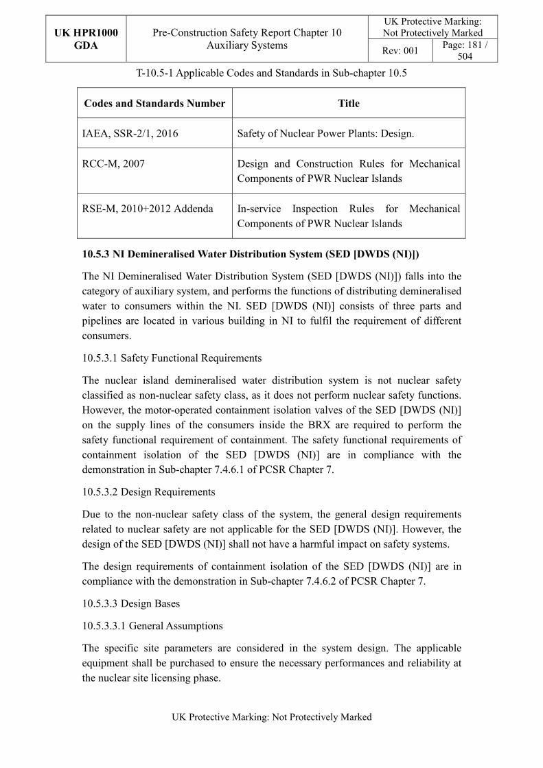
UK HPR1000
GDA
Pre-Construction Safety Report Chapter 10 Auxiliary Systems
UK Protective Marking: Not Protectively Marked
Rev: 001 Page: 181 /
504
UK Protective Marking: Not Protectively Marked
T-10.5-1 Applicable Codes and Standards in Sub-chapter 10.5
Codes and Standards Number Title
IAEA, SSR-2/1, 2016 Safety of Nuclear Power Plants: Design.
RCC-M, 2007 Design and Construction Rules for Mechanical Components of PWR Nuclear Islands
RSE-M, 2010+2012 Addenda In-service Inspection Rules for Mechanical Components of PWR Nuclear Islands
10.5.3 NI Demineralised Water Distribution System (SED [DWDS (NI)])
The NI Demineralised Water Distribution System (SED [DWDS (NI)]) falls into the category of auxiliary system, and performs the functions of distributing demineralised water to consumers within the NI. SED [DWDS (NI)] consists of three parts and pipelines are located in various building in NI to fulfil the requirement of different consumers.
10.5.3.1 Safety Functional Requirements
The nuclear island demineralised water distribution system is not nuclear safety classified as non-nuclear safety class, as it does not perform nuclear safety functions. However, the motor-operated containment isolation valves of the SED [DWDS (NI)] on the supply lines of the consumers inside the BRX are required to perform the safety functional requirement of containment. The safety functional requirements of containment isolation of the SED [DWDS (NI)] are in compliance with the demonstration in Sub-chapter 7.4.6.1 of PCSR Chapter 7.
10.5.3.2 Design Requirements
Due to the non-nuclear safety class of the system, the general design requirements related to nuclear safety are not applicable for the SED [DWDS (NI)]. However, the design of the SED [DWDS (NI)] shall not have a harmful impact on safety systems.
The design requirements of containment isolation of the SED [DWDS (NI)] are in compliance with the demonstration in Sub-chapter 7.4.6.2 of PCSR Chapter 7.
10.5.3.3 Design Bases
10.5.3.3.1 General Assumptions
The specific site parameters are considered in the system design. The applicable equipment shall be purchased to ensure the necessary performances and reliability at the nuclear site licensing phase.
UK HPR1000
GDA
Pre-Construction Safety Report Chapter 10 Auxiliary Systems
UK Protective Marking: Not Protectively Marked
Rev: 001 Page: 182 /
504
UK Protective Marking: Not Protectively Marked
10.5.3.3.2 Design Assumptions
The nuclear island demineralised water distribution system is designed to meet the plant demand for demineralised water of the plant under any operational conditions.
In the UK HPR1000, the operating parameters of the nuclear island demineralised water distribution system are designed accordingly. The operating pressures of the SED [DWDS (NI)] are designed to meet the requirements of the downstream users. Based on the different users, the SED [DWDS (NI)] is designed to be with three sub-systems, demineralised water distribution system within BWX and demineralised water distribution system within buildings in the nuclear island, and seal water sub-system.
In the SED [DWDS (NI)], the containment isolation valves are designed to reduce the leakage of radioactive material in the event of an accident.
The single failure criterion is applicable to the containment isolation valves.
The SED [DWDS (NI)] design bases of containment isolation are in compliance with the demonstration in Sub-chapter 7.4.6.3 of PCSR Chapter 7.
10.5.3.4 System Description and Operation
10.5.3.4.1 System Description
a) General System Description
The SED [DWDS (NI)] is designed to ensure the supply of neutral demineralised water which is produced by the Demineralised Water Production System (SDA [DWPS]), and required by various circuits and equipment contained within the nuclear island.
The SED [DWDS (NI)] is divided into following three sub-systems:
1) SED3: distributes demineralised water to consumers within the Radioactive Waste Processing Building (BWX);
2) SED4: distributes demineralised water to consumers within buildings in the nuclear island;
3) SED5: seal water sub-system to ensure the supply of demineralised water with high pressure.
Each sub-system of SED [DWDS (NI)] distributes demineralised water to consumers during DBC-1, and the seal water sub-system also distributes seal water to consumers during DBC-2.
b) Description of Main Equipment
1) Seal Water Pumps
UK HPR1000
GDA
Pre-Construction Safety Report Chapter 10 Auxiliary Systems
UK Protective Marking: Not Protectively Marked
Rev: 001 Page: 183 /
504
UK Protective Marking: Not Protectively Marked
2×100% centrifugal pumps are designed to ensure the pressure of seal water sub-system.
2) Startup Filter
At the inlet of the BNX a start-up filter filters the demineralised water. The startup filter is installed during commissioning; no bypass or pressure gauges are needed. After commissioning the filter will be removed and replaced by a flanged spool piece.
3) Seal Water Storage Tank
A seal water storage tank is designed to provide inlet demineralised water to the seal water pumps.
c) Description of Main Layout
The SED [DWDS (NI)] piping enters the BNX and BWX via the site gallery. Pipelines of the SED [DWDS (NI)] are arranged in NI buildings including the BWX, BRX, BNX, Fuel Building (BFX), Safeguard Building A (BSA), Safeguard Building B (BSB), Safeguard Building C (BSC) and diesel generator buildings.
d) Description of System Interfaces
The demineralised water in SED [DWDS (NI)] is pumped from the demineralised water storage tank by demineralised water pumps of SDA [DWPS]. The consumer systems of SED [DWDS (NI)] are listed as follows:
1) Radioactive Decontamination System (SBD [RDS]);
2) Solid Waste Treatment System (TES [SWTS]);
3) Liquid Waste Treatment System (TEU [LWTS]);
4) Steam Generator Blowdown System (APG [SGBS]);
5) Fuel Pool Cooling and Treatment System (PTR [FPCTS]);
6) Reactor Coolant System (RCP [RCS]);
7) Reactor Boron and Water Makeup System (REA [RBWMS]);
8) Nuclear Sampling System (REN [NSS]);
9) Nuclear Island Vent and Drain System (RPE [VDS]);
10) Component Cooling Water System (RRI [CCWS]);
11) Gaseous Waste Treatment System (TEG [GWTS]);
12) Coolant Storage and Treatment System (TEP [CSTS]);

UK HPR1000
GDA
Pre-Construction Safety Report Chapter 10 Auxiliary Systems
UK Protective Marking: Not Protectively Marked
Rev: 001 Page: 184 /
504
UK Protective Marking: Not Protectively Marked
13) Extra Cooling System (ECS [ECS]);
14) Safety Injection System (RIS [SIS]);
15) Auxiliary Steam Production System (XCA [ASPS]);
16) Atmospheric Steam Dump System (VDA [ASDS]);
17) Containment Filtration and Exhaust System (EUF [CFES]);
18) Chemical and Volume Control System (RCV [CVCS]);
19) NI 10kV Emergency Power Distribution System (LH [EPDS(NI-10kV)]);
20) Safety Chilled Water System (DEL [SCWS]);
21) Operational Chilled Water System (DER [OCWS]);
22) Waste Treatment Building Chilled water System (DEQ [WTBCWS]);
10.5.3.4.2 System Operation
a) Plant Normal Conditions
In plant normal conditions, SED [DWDS (NI)] supplies demineralised water to the consumers in the NI. The containment isolation valves are open. One of the two seal water pumps is continuously running to deliver the seal water flow at the required pressure and flowrate.
b) Plant Fault or Accident Conditions
The containment isolation valves are closed by the Reactor Protection System in the event of LOCA.
10.5.3.5 Preliminary Design Substantiation
10.5.3.5.1 Compliance with Safety Functional Requirements
The demineralised water distribution system is not required to perform nuclear safety functions. The functional category of the demineralised water distribution system is NC. Compliance with safety requirements of the SED [DWDS (NI)] containment isolation is in compliance with the demonstration in Sub-chapter 7.4.6.5.1 of PCSR Chapter 7.
10.5.3.5.2 Compliance with Design Requirements
The operational pressure and temperature of the nuclear island demineralised water distribution system is designed to meet the requirements of downstream users.
To ensure the reliability of the systems, the commissioning tests of the nuclear island demineralised water distribution system is completed before the start-up of the plant, and the systems is subject to continuous monitoring to meet operational requirements.
UK HPR1000
GDA
Pre-Construction Safety Report Chapter 10 Auxiliary Systems
UK Protective Marking: Not Protectively Marked
Rev: 001 Page: 185 /
504
UK Protective Marking: Not Protectively Marked
All equipment that operates periodically are additionally examined, checked and repaired. Compliance with design requirements of the SED [DWDS (NI)] containment isolation is in compliance with the demonstration in Sub-chapter 7.4.6.5.2 of PCSR Chapter 7. The system specific demonstrations are as follows:
a) Compliance with Engineering Design Requirements
1) Reliability Design of SSCs
- Independence
The two containment isolation valves are physically separated by the installation location, one inside and the other outside the containment.
- Diversity
The containment isolation valves design in the system is compliant with the diversity principles. The internal containment isolation valves and the external containment isolation valves installed at the demineralised water distribution line will be designed and provided by different manufacturers.
- Fail-safe
The fail-safe concept is considered in the SED [DWDS (NI)] containment isolation design process. After comprehensive analysis, other measures such as redundancy are used to improve safety in order to avoid the potential safety risks that may be introduced by “fail-safe” design on power plant.
- Ageing and Degradation
The containment isolation valves and penetrations of SED [DWDS (NI)] are designed for the 60-year operation. The design considerations and measures described in Sub-chapter 10.2.4 are applied in the design of SED [DWDS (NI)].
2) Human Factors
The SED [DWDS (NI)] considers the requirements stated in Sub-chapter 10.2.4 and the design considerations and measures described in Sub-chapter 10.2.4 are applied in the design of SED [DWDS (NI)].
3) Autonomy
- Autonomy in Respect of Operators
The design principles relevant to the autonomy in respect of operators are detailed in Sub-chapter 10.2.4. The design of SED [DWDS (NI)] fulfils these principles via control functional design.
UK HPR1000
GDA
Pre-Construction Safety Report Chapter 10 Auxiliary Systems
UK Protective Marking: Not Protectively Marked
Rev: 001 Page: 186 /
504
UK Protective Marking: Not Protectively Marked
- Autonomy in Respect of Heat Sink
Not applicable.
- Autonomy in Respect of Power Supply Systems
The safety classified components, such as the containment isolation valves, are all supplied by EDGs.
4) Other Design Requirements
- Prevention of Harmful Interactions of Systems Important to Safety
Not applicable.
- Considerations Related to the Electrical Power Grid
The design of active components such as the containment isolation valves has taken disturbances in the electrical power grid into consideration.
b) Equipment Qualification
The SED [DWDS (NI)] containment isolation valves should be capable of operating under normal conditions and accidental conditions, which requires the components to withstand the most penalised ambient environment conditions.
The SED [DWDS (NI)] containment isolation valves which are seismically classified operate during and after the SSE. The components are seismically designed and qualified against SSE loads.
c) Protection against Internal and External Hazards
The SED [DWDS (NI)] complies with the requirements stated in Sub-chapter 10.2.4 and design considerations and measures described in Sub-chapter 10.2.4 are applied in the design of SED [DWDS (NI)].
d) Commissioning
Commissioning and tests shall be carried out for the SED [DWDS (NI)] containment isolation valves to valid their functionality.
e) Examination, Inspection, Maintenance and Testing
1) Inspections and Surveillances
The SED [DWDS (NI)] should be periodically tested including a pressure test and nondestructive inspection. The safety valves should be tested periodically.
2) Maintenance
UK HPR1000
GDA
Pre-Construction Safety Report Chapter 10 Auxiliary Systems
UK Protective Marking: Not Protectively Marked
Rev: 001 Page: 187 /
504
UK Protective Marking: Not Protectively Marked
Maintenance of the SED [DWDS (NI)] is performed according to the corresponding industrial codes and guidelines. SED [DWDS (NI)] valves should be easily accessible.
Preventive maintenance on the SED [DWDS (NI)] components is performed according to the specifications of manufactures and the category of materials. The safety classified components (containment penetration and containment isolation valves) are inspected periodically.
The valves may only be maintained when the plant is in shutdown. Annual testing should be performed to check that the various valves are operable and watertight.
3) Periodic Tests
Safety valves, isolation valves, check valves in SED [DWDS (NI)] should be tested periodically.
f) Material Selection
All parts of the SED [DWDS (NI)] are made of stainless steel as untreated demineralised water can be corrosive.
g) Special Thermal-hydraulic Phenomena
The design of the SED [DWDS (NI)] considers the prevention of harmful thermal-hydraulic phenomena such as water hammer.
h) Insulation
Not applicable.
10.5.4 Nuclear Island Potable Water System (SEP [PWS (NI)])
The SEP [PWS (NI)] falls into the category of Process Auxiliary System, and performs the functions of transferring potable water to each user.
10.5.4.1 Safety Functional Requirements
The SEP [PWS (NI)] is not required to perform safety functions. The SEP [PWS (NI)] needs to be physically separated from all radioactive sources and from any system that may contain substances dangerous to health. Therefore, the SEP [PWS (NI)] does not need to perform during the DBC-2, DBC-3, DBC-4 and DEC events.
10.5.4.1.1 Control of Reactivity
Not applicable.
10.5.4.1.2 Removal of Heat
Not applicable.
UK HPR1000
GDA
Pre-Construction Safety Report Chapter 10 Auxiliary Systems
UK Protective Marking: Not Protectively Marked
Rev: 001 Page: 188 /
504
UK Protective Marking: Not Protectively Marked
10.5.4.1.3 Confinement
Not applicable
10.5.4.1.4 Extra Safety Functions
Not applicable
10.5.4.2 Design Requirements
The SEP [PWS (NI)] is not a safety-classified system, therefore, most of the general design requirements listed in Sub-chapter 10.2.4 need not to be complied with.
10.5.4.3 Design Bases
There are no quantitative safety-related design assumptions for the SEP [PWS (NI)].
10.5.4.4 System Description and Operation
10.5.4.4.1 System Description
a) General System Description
The SEP [PWS] (NI) distributes potable water to users with a piping network, arranged outside the wall in building. The system mainly consists of valves, pipes and water appliances.
The potable water systems are of two types:
1) Sanitary Needs
The potable water system in Nuclear Island provides potable water to the toilet, kitchen, dining room, tea room in safeguard building and bathroom, toilet in access building.
2) Industrial Needs
The potable water system in the nuclear island provides potable water to eyewash equipment and the hot laundry facility in the waste treatment building, and also to eyewash equipment in safeguard building.
b) Description of Main Equipment
The specific water appliances will be provided at the site specific stage.
c) Description of Main Layout
The branch pipe of the SEP [PWS (NI)] can be connected from the outdoor looped piping network of site SEP [PWS (NI)]. The pipes of the SEP [PWS (NI)] are located separately in BSA, BSB, BSC, BNX, Personnel Access Building (BPX), BWX, BPA and BPB.
d) Description of System Interfaces
UK HPR1000
GDA
Pre-Construction Safety Report Chapter 10 Auxiliary Systems
UK Protective Marking: Not Protectively Marked
Rev: 001 Page: 189 /
504
UK Protective Marking: Not Protectively Marked
The consumer systems of the SEP [PWS (NI)] are listed as follows:
1) Main Control Room Air Conditioning System (DCL [MCRACS]);
2) Electrical Division of Safeguard Building Ventilation System (DVL [EDSBVS);
3) Essential Service Water System (SEC [ESWS]);
4) Hot Laundry System (SBE [HLS]).
e) Description of Instrumentation and Control
The SEP [PWS (NI)] has no control function.
10.5.4.4.2 System Operation
a) Plant Normal Conditions
The SEP [PWS (NI)] is an automatic system in normal conditions, and is supplied by outdoor piping network.
b) Plant Fault or Accident Conditions
The SEP [PWS (NI)] is not used in plant accident conditions.
10.5.4.5 Preliminary Design Substantiation
a) Safety Requirements
The SEP [PWS (NI)] is not required to perform nuclear safety functions.
b) Commissioning and Testing
The SEP [PWS (NI)] is not subject to periodic tests. The equipment of the SEP [PWS (NI)] should be maintained according to the maintenance manual supplied by the equipment provider.
c) Human Factors
The concept of human factors is taken into consideration in the SEP [PWS (NI)] design. The layout of the equipment and the valves is designed to facilitate maintenance. The detailed layout will be provided during the nuclear site licensing phase.
10.5.5 Nuclear Island Gas Distribution Systems (SGO [ODS], SGN [NDS], SGH
[HDS (NI)])
10.5.5.1 Safety Functional Requirements
The nuclear island gas distribution systems are not nuclear safety classified, as they do not perform nuclear safety functions. However, pipelines running through the containment building and related valves are required to be F-SC1 safety class.
UK HPR1000
GDA
Pre-Construction Safety Report Chapter 10 Auxiliary Systems
UK Protective Marking: Not Protectively Marked
Rev: 001 Page: 190 /
504
UK Protective Marking: Not Protectively Marked
10.5.5.2 Design Requirements
Due to the systems not being nuclear safety classified, the general design requirements related to nuclear safety are not applicable for the nuclear island gas distribution systems. However, the design of the nuclear island gas distribution systems shall not have a harmful impact on safety systems.
The design requirements of containment isolation of the SGN [NDS] are in compliance with the demonstration in PCSR Sub-chapter 7.4.6.2.
10.5.5.3 Design Bases
10.5.5.3.1 General Assumptions
The specific site parameters are considered in the system design. Applicable equipment is designed and purchased to ensure the necessary performance and reliability in the nuclear site licensing phase.
10.5.5.3.2 Design Assumptions
The nuclear island gas distribution systems are designed to meet the plant demand for nitrogen, oxygen and hydrogen under any operational conditions.
In the UK HPR1000, the operating parameters of the gas distribution systems are designed accordingly. The operating pressures of the SGH [HDS (NI)] and SGO [ODS] are designed to meet the requirements of the downstream users. Based on the different users, the SGN [NDS] is designed with two sub-systems, a high pressure nitrogen distribution system and a low pressure nitrogen distribution system.
In the SGN [NDS], the containment isolation valves are designed to reduce the leakage of radioactive material in the event of an accident.
Precautionary measures are taken to prevent the content of nitrogen, as an inert gas, from rising to a certain concentration that threatens the lives of the staff.
Measures are taken on the hydrogen pipelines to avoid possible explosions caused by gas leakage.
The SFC is applicable to the containment isolation valves.
10.5.5.4 System Description and Operation
10.5.5.4.1 System Description
The nuclear island gas distribution systems provide nitrogen, oxygen and hydrogen for systems and equipment of the NI. The distribution networks consist of valves, pressure reducing valves, and pipelines connecting to the user systems and equipment. Nitrogen and oxygen comes from the service gas storage zone and hydrogen from the hydrogen station, located in the area of Balance of Plant (BOP). The nuclear island gas distribution systems provide gases for the following systems:
UK HPR1000
GDA
Pre-Construction Safety Report Chapter 10 Auxiliary Systems
UK Protective Marking: Not Protectively Marked
Rev: 001 Page: 191 /
504
UK Protective Marking: Not Protectively Marked
a) Reactor Coolant System (RCP [RCS]);
b) Fuel Pool Cooling and Treatment System (PTR [FPCTS]);
c) Safety Injection System (RIS [SIS]);
d) Chemical and Volume Control System (RCV [CVCS]);
e) Coolant Storage and Treatment System (TEP [CSTS]);
f) Reactor Boron and Water Makeup System (REA [RBWMS]);
g) Gaseous Waste Treatment System (TEG [GWTS]);
h) Nuclear Sampling System (REN [NSS]);
i) Steam Generator Blowdown System (APG [SGBS]).
The nuclear island gas distribution systems include the SGN [NDS], SGO [ODS] and SGH [HDS (NI)]. They are designed according to the maximum consumption of gas users under all operational conditions. The gas distribution system mainly includes the following pipelines:
a) Gas Distribution Pipelines;
b) Gas Pressure Reducing Pipelines;
c) Overpressure Protection Pipelines;
d) Test Relief and Drain Pipelines.
10.5.5.4.2 System Operation
a) Plant Normal Conditions
The nuclear island gas distribution systems can operate during the plant normal operation and outage stage.
The operability of downstream auxiliary systems, including RCV [CVCS] and TEG [GWTS], will be affected by the failure of the hydrogen distribution system. As the time since failure increases, the hydrogen concentration in the reactor coolant cannot be maintained within the required operating range.
When the safety signal is activated, the containment isolation valves of the nitrogen distribution system will be closed.
b) Plant Accident Conditions
The nuclear island gas distribution systems do not operate when the NPP is in transient or accidental conditions.
UK HPR1000
GDA
Pre-Construction Safety Report Chapter 10 Auxiliary Systems
UK Protective Marking: Not Protectively Marked
Rev: 001 Page: 192 /
504
UK Protective Marking: Not Protectively Marked
10.5.5.5 Preliminary Design Substantiation
10.5.5.5.1 Compliance with Safety Functional Requirements
The nuclear island gas distribution systems are not required to perform nuclear safety functions. The functional category of the nuclear island gas distribution systems is NC. However, pipelines running through the containment building and related valves are designed to be F-SC1 safety class.
10.5.5.5.2 Compliance with Design Requirements
The operational pressures and temperature of the nuclear island gas distribution systems are designed to meet the requirements of downstream users.
The design substantiation of containment isolation of the SGN [NDS] is in compliance with the demonstration in PCSR Sub-chapter 7.4.6.5.
To ensure the reliability of the systems, the commissioning tests of the nuclear island gas distribution systems are completed before the start-up of the plant, and the systems are subject to continuous monitoring to meet operational requirements. All equipment that operates periodically are additionally examined, checked and repaired.
10.5.6 Compressed Air Distribution Systems (SAP [CAPS], SAR [ICADS] SAT
[SCADS])
10.5.6.1 Safety Functional Requirements
The compressed air distribution systems are not nuclear safety classified, as they do not perform nuclear safety functions. However, pipelines running through the containment building and related valves are required to be F-SC1 safety class.
10.5.6.2 Design Requirements
Due to not being nuclear safety classified, the general design requirements related with nuclear safety are not applicable for the compressed air distribution systems. However, the design of the compressed air distribution systems shall not have a harmful impact on the safety systems.
To support essential systems, the availability of compressed air reserves shall be consistent with the timescale for the availability of the equipment.
The design requirements of containment isolations are in compliance with the demonstration in PCSR Sub-chapter 7.4.6.2.
10.5.6.3 Design Bases
10.5.6.3.1 General Assumptions
The specific site parameters are considered in the system design. The applicable equipment is designed and purchased to ensure the necessary performance and
UK HPR1000
GDA
Pre-Construction Safety Report Chapter 10 Auxiliary Systems
UK Protective Marking: Not Protectively Marked
Rev: 001 Page: 193 /
504
UK Protective Marking: Not Protectively Marked
reliability in the nuclear site licensing phase.
10.5.6.3.2 Design Assumptions
The compressed air systems are designed to meet the following requirements:
a) The requirements for the instrument and service compressed air from consumers, during normal operation and plant outage;
b) When the instrument compressed air is unavailable, all pneumatic valves will be in the fail-safe position;
c) Multiple air compressors are provided;
d) When one compressor fails to operate, the standby air compressors can start to pressurise the pipe network. During the switch-over period, the capacity of the dedicated storage tanks is sufficient to supply the required air to the pneumatic control devices;
e) In addition to the pressure gauge, each air storage tank is also equipped with a safety valve to prevent over-pressure;
f) The pressure ranges of the SAR [ICADS] and SAT [SCADS] are different, and priority is given to the demand of the SAR [ICADS] in the NI.
10.5.6.4 System Description and Operation
10.5.6.4.1 System Description
The compressed air systems consist of the following systems:
a) SAP [CAPS];
b) SAR [ICADS];
c) SAT [SCADS].
The compressed air distribution systems provide clean and dry compressed air for systems and equipment of the power plant. The distribution networks consist of valves, air storage tanks, and pipelines connecting the user system and equipment.
The SAP [CAPS] provides compressed air to the SAR [ICADS] and SAT [SCADS], which provides instrument and service compressed air to the users of NI, Conventional Island (CI), and BOP buildings.
Several compressors and their auxiliary equipment (valves, dryers, filters, etc.) are design for the SAP [CAPS], which can produce compressed air to meet various demands for compressed air in the NPP.
According to the different users, the SAR [ICADS] is divided into NI pipe network, CI pipe network and BOP pipe network. This also applies to the SAT [SCADS].
UK HPR1000
GDA
Pre-Construction Safety Report Chapter 10 Auxiliary Systems
UK Protective Marking: Not Protectively Marked
Rev: 001 Page: 194 /
504
UK Protective Marking: Not Protectively Marked
10.5.6.4.2 System Operation
When the pressure of the main air supply pipe drops to the pre-set threshold, the standby compressors start to operate. If all compressors have started and the pressure still drops, the back pressure control valves in the pipe network will be activated and an alarm signal will be sent to the MCR.
Both the SAT [SCADS] and SAR [ICADS] are connected to the SAP [CAPS]. And, there is no direct connection between the SAT [SCADS] and the SAR [ICADS]. The compressed air pipe networks are equipped with check valves and back-pressure control valves to ensure that:
a) When a fault occurs in the compressed air systems and some users should be isolated, priority is given to the users of the SAR [ICADS] (cutting off air supply to the SAT [SCADS]);
b) When the fault continues to develop in the compressed air systems and other users should be isolated, priority is given to the users of the SAR [ICADS] in the NI (cutting off air supply to the SAR [ICADS] in the CI and BOP).
10.5.6.5 Preliminary Design Substantiation
10.5.6.5.1 Compliance with Safety Functional Requirements
The compressed air distribution systems are not required to perform nuclear safety functions and are therefore not nuclear safety classified. The classification of the containment isolation valves is F-SC1 and it is consistent with the safety functional requirements.
10.5.6.5.2 Compliance with Design Requirements
For each system which carries out nuclear safety functions and has a requirement for compressed air, a compressed air storage tank is included in the system to ensure the availability of compressed air. The capacity of the tank is determined according to the design requirement of each safety system.
The design substantiation for containment isolation of the SAT [SCADS] is in compliance with the demonstration in PCSR Sub-chapter 7.4.6.5. Containment isolation of the SAT [SCADS] is performed by two manual cut-off valves, which are kept closed during normal operation. During the outage of the NPP, containment isolation is not required and the two valves are opened to supply service compressed air for maintenance.
The following items are inspected on a regular basis during the service life of the NPP to ensure their reliability:
a) Operability of Isolation Valves in Pipe Networks;
b) Airtightness of Air Circuits;
UK HPR1000
GDA
Pre-Construction Safety Report Chapter 10 Auxiliary Systems
UK Protective Marking: Not Protectively Marked
Rev: 001 Page: 195 /
504
UK Protective Marking: Not Protectively Marked
c) Working Conditions of the Air Storage Tanks.
Hydrostatic testing is carried out on the air storage tanks of the compressed air systems. For the UK HPR1000, the hydrostatic test pressure of the air storage tank is larger than the design pressure of the relevant system.
10.5.7 ALARP Assessment
10.5.7.1 General Description
A Preliminary ALARP analysis has been performed on the process auxiliary systems. The analysis is consistent with the arguments stated in the Sub-claim 3.3.6.SC10.3 of the route map presented in Appendix B:
Argument 3.3.6.SC10.3-1: The SSCs meet the requirements of the relevant design principles (generic and system specific) and therefore of RGP;
The ALARP assessment is carried out following the ALARP methodology presented in Chapter 33. A specific ALARP demonstration report has been prepared, Reference [14].
10.5.7.2 Review of Design against RGP & OPEX
The RGP for SSCs design is identified, and suitable analysis against the applicable codes and standards identified for the SSCs design in the ME area are carried out in Reference [13]. Consistency analysis between current design and RGP is still under development to ensure that the design of the SSC meets the requirements of the UK context.
Consistency analysis between current design and the OPEX from multiple reactors such as the UK AP1000 and the UK EPR is also under development to identify potential improvements to the current design.
10.5.7.3 Insights from Risk Analysis
The risk analysis is currently being developed and a preliminary result has been produced. No insight was received for the design of the process auxiliary systems this preliminary analysis currently. The analysis will continue as the GDA phase progresses.
Potential areas of system design improvement will be identified through the further risk assessment to reduce the risks to ALARP. The ALARP demonstration topic report will be updated if any gap is identified.
10.5.7.4 Specific Review of Potential Improvements
Optioneering will be performed after any gap is identified. At this stage, no gap is identified.
UK HPR1000
GDA
Pre-Construction Safety Report Chapter 10 Auxiliary Systems
UK Protective Marking: Not Protectively Marked
Rev: 001 Page: 196 /
504
UK Protective Marking: Not Protectively Marked
10.5.7.5 ALARP Demonstration
A compliance analysis of the process auxiliary systems design with respect to the UK HPR1000 general safety engineering principles is made in the system section of each sub-chapter. The analysis shows that the design of the SSC meets relevant requirements and no gaps have been identified. A systematic review will be carried out on the system design to ensure that no new gaps are identified between the newly developed requirements and the design. Any potential enhancements identified during this review will be taken into account during further design development.
In summary, ALARP analysis and demonstration work is currently being carried out. A preliminary ALARP demonstration topic report to present the current analysis results as well as the arrangements for future ALARP analysis work is presented in Reference [14].
10.5.8 Concluding Remarks
This sub-chapter provides an introduction of the design information for the process auxiliary systems in the UK HPR1000.
As various technical areas are currently under development, which may influence the current design, a systematic review will be carried out after the work has been finished. If any gap is identified during the technical review, an ALARP demonstration will be carried out and effort will be made to reduce the risk to ALARP.
10.6 Heating, Ventilation and Air Conditioning (HVAC) Systems
10.6.1 Sub-chapter Structure
The structure of Sub-chapter 10.6 is as follows:
a) Sub-chapter 10.6.1 (Sub-chapter Structure) gives the overall structure of Sub-chapter 10.6;
b) Sub-chapter 10.6.2 (Applicable Codes and Standards) presents the relevant codes and standards adopted in this Sub-chapter;
c) Sub-chapters 10.6.3 to 10.6.18 present the following HVAC systems:
1) 10.6.3 Nuclear Auxiliary Building Ventilation System (DWN [NABVS]);
2) 10.6.4 Fuel Building Ventilation System (DWK [FBVS]);
3) 10.6.5 Containment Cooling and Ventilation System (EVR [CCVS]);
4) 10.6.6 Containment Internal Filtration System (EVF [CIFS]);
5) 10.6.7 Containment Sweeping and Blowdown Ventilation System (EBA [CSBVS]);
UK HPR1000
GDA
Pre-Construction Safety Report Chapter 10 Auxiliary Systems
UK Protective Marking: Not Protectively Marked
Rev: 001 Page: 197 /
504
UK Protective Marking: Not Protectively Marked
6) 10.6.8 Annulus Ventilation System (EDE [AVS]);
7) 10.6.9 Safeguard Building Controlled Area Ventilation System (DWL [SBCAVS]);
8) 10.6.10 Electrical Division of Safeguard Building Ventilation System (DVL [EDSBVS]);
9) 10.6.11 Main Control Room Air Conditioning System (DCL [MCRACS]);
10) 10.6.12 Access Building Ventilation Systems (DVW [ABUAVS]-DWW [ABCAVS]);
11) 10.6.13 Diesel Building Ventilation System (DVD [DBVS]);
12) 10.6.14 Essential Service Water Pumping Station Ventilation System (DXS [ESWVS]);
13) 10.6.15 Extra Cooling Water and NI Firefighting Building Ventilation System (DXE [ECW&FFB VS]);
14) 10.6.16 Waste Treatment Building Ventilation System (DWQ [WTBVS])
15) 10.6.17 Safety Chilled Water System (DEL [SCWS])
16) 10.6.18 Operational Chilled Water System (DER [OCWS])
d) Sub-chapter 10.6.19 (ALARP Assessment) gives the preliminary ALARP analysis of this Sub-chapter;
e) Sub-chapter 10.6.20 (Concluding Remarks) gives the summary and the on-going work of this Sub-chapter;
f) Sub-chapter 10.6.21 (Simplified Diagrams) present the simplified diagrams of the HVAC systems mentioned in Sub-chapters 10.6.3 to 10.6.18;
g) Sub-chapter 10.6.22 (Tables of Design Assumptions) gives common design assumptions used in Sub-chapters 10.6.3 to 10.6.18.
10.6.2 Applicable Codes and Standards
The identification of applicable codes and standards in Sub-chapter 10.6 is compliant with the general principles of codes and standards selection stated in Chapter 4 and Reference [12].
Wherever possible, the standards applied for the engineering substantiation should be:
a) Internationally recognised in nuclear industry;
b) The latest or currently applicable approved standards; and
c) Consistent with the plant reliability goals necessary for safety.
UK HPR1000
GDA
Pre-Construction Safety Report Chapter 10 Auxiliary Systems
UK Protective Marking: Not Protectively Marked
Rev: 001 Page: 198 /
504
UK Protective Marking: Not Protectively Marked
Based on the principles mentioned above, the applicable codes and standards intended to be used in the UK HPR1000 design in the Mechanical Engineering (ME) discipline are identified. During GDA step 2, the suitable analysis against the applicable codes and standards identified for the SSCs design in ME area are carried out in the Reference [13]. Then in step 3, a compliance analysis is carried out and presented in Reference [14]. Main applicable codes and standards for HVAC systems design are presented in Table T-10.6-1.
Currently, the work of conformity analysis and gap analysis of the codes and standards is continuing.
T-10.6-1 Applicable Codes and Standards in Sub-chapter 10.6
Codes and Standards Number Title
BS ISO 26802, 2010 Nuclear Facilities — Criteria for the Design and the Operation of Containment and Ventilation Systems for Nuclear Reactors
ISO 17873, 2004 Nuclear Facilities — Criteria for the Design and Operation of Ventilation Systems for Nuclear Installations Other Than Nuclear Reactors
EG_0_1738_1, 2018 Ventilation Systems for Radiological Facilities Design Guide
10.6.3 Nuclear Auxiliary Building Ventilation System (DWN [NABVS])
The DWN [NABVS] is a ventilation system which provides fresh air and filters the exhaust air for the nuclear auxiliary building, fuel building, safeguard building and reactor building to maintain the room ambient conditions and reduce airborne radioactivity released to the external environment during plant normal conditions. Information of the system is presented in the SDM chapter 2, Reference [72].
10.6.3.1 Safety Functional Requirements
10.6.3.1.1 Control of Reactivity
The DWN [NABVS] does not contribute to this safety function.
10.6.3.1.2 Removal of Heat
The DWN [NABVS] does not contribute to this safety function.
10.6.3.1.3 Confinement
With respect to its contribution to confinement, the DWN [NABVS] must satisfy the following requirements:
UK HPR1000
GDA
Pre-Construction Safety Report Chapter 10 Auxiliary Systems
UK Protective Marking: Not Protectively Marked
Rev: 001 Page: 199 /
504
UK Protective Marking: Not Protectively Marked
a) Environmental Protection
The DWN [NABVS] system carries gaseous fluids containing radioactive material. So it must contribute:
1) to the confinement of this material with respect to the environment;
2) to the control and reduction of radioactive material discharge under normal operation.
b) Limiting Radiological Consequences
The DWN [NABVS] system must contribute to the static confinement of the Nuclear Auxiliary Building (BNX) in the event of multiple failures of systems in the BNX building following an earthquake.
10.6.3.1.4 Extra Safety Functions
The extra safety functional requirements of the DWN [NABVS] are identified below:
a) Supporting the Fundamental Safety Functions
The DWN [NABVS] contributes indirectly to the fundamental safety function of confinement of radioactive material as a support system as follows:
1) The DWN [NABVS] system must contribute to the provision of a pressure reference in order for:
- the Fuel Building Ventilation System (DWK [FBVS]) to confine the controlled area of the Fuel Building (BFX) during normal operation;
- the Safeguard Building Controlled Area Ventilation System (DWL [SBCAVS]) to confine the controlled area of the Safeguard Buildings (BSX) during normal operation;
- the Waste Treatment Building Ventilation System (DWQ [WTBVS]) to confine the controlled area of the radioactive waste treatment building during normal operation.
b) Prevent, Protect and Mitigate Hazards Impact
Internal fire:
In the event of fire, the DWN [NABVS] contributes to limit fire spread.
10.6.3.2 Design Requirements
The general design requirements of the HVAC systems which need to be considered are shown in Sub-chapter 10.2.4, among which the following requirements are not applicable for the DWN [NABVS]:
a) Autonomy in Respect of Operators
UK HPR1000
GDA
Pre-Construction Safety Report Chapter 10 Auxiliary Systems
UK Protective Marking: Not Protectively Marked
Rev: 001 Page: 200 /
504
UK Protective Marking: Not Protectively Marked
Not applicable, because the design principles relevant to the autonomy in respect of operators are not applicable for DWN [NABVS] design.
b) Autonomy in Respect of the Heat Sink
Not applicable, because the DWN [NABVS] system doesn’t provide a heat sink to the power plant.
c) Autonomy in Respect of Power Supply Systems
Not applicable, because the DWN [NABVS] system doesn’t provide power supply to the power plant.
d) Prevention of Harmful Interactions of Systems Important to Safety
Not applicable, because the DWN [NABVS] doesn’t have harmful interactions of systems important to safety.
The substantiation analysis of the DWN [NABVS] to other design requirements is shown in the Sub-chapter 10.6.3.5.2.
10.6.3.3 Design Bases
10.6.3.3.1 General Assumptions
The DWN [NABVS] air supply subsystem consists of 3×33% fresh air treatment trains and 4×50% air supply fans.
The DWN [NABVS] High Efficiency Particulate Air (HEPA) filtration line is made up of 7 trains and 4×50% air exhaust fans.
The DWN [NABVS] iodine adsorption units’ line is made up of 4×25% trains and 4×25% booster fans. Each iodine adsorption train is capable of filtering the air flow coming from any DWN [NABVS] HEPA filtration cell.
10.6.3.3.2 Design Assumptions
a) Control of Reactivity
Not applicable. The DWN [NABVS] system does not contribute to the safety function of control of reactivity.
b) Removal of Heat
Not applicable. The DWN [NABVS] does not contribute to the safety function of removal of heat.
c) Confinement
1) Environmental Protection
- During normal operation, the DWN [NABVS] must contribute to the
UK HPR1000
GDA
Pre-Construction Safety Report Chapter 10 Auxiliary Systems
UK Protective Marking: Not Protectively Marked
Rev: 001 Page: 201 /
504
UK Protective Marking: Not Protectively Marked
confinement of radioactive material by maintaining a negative pressure in the controlled area of the BNX building relative to the atmospheric pressure.
- During normal operation, the DWN [NABVS] must contribute to limiting the radioactivity of the air discharged into the vent stack. The filtration requirements for this criterion are:
• HEPA filters: decontamination factor see Table T-10.6-40;
• Iodine adsorption units: decontamination factor see Table T-10.6-41;
• Iodine adsorption units’ heaters: the heaters upstream of the iodine adsorbers are designed to maintain the relative humidity below 70%.
2) Limiting Radiological Consequences
Following an earthquake event, the DWN [NABVS] must ensure that the isolation of air entry and exhaust in the nuclear auxiliary building meets the air-tightness requirements stated in Table T-10.6-38.
d) Extra Safety Functions
1) Supporting the Fundamental Safety Functions
Not applicable. There is no quantitative safety-related design assumption associated with the DWN [NABVS].
2) Prevent, Protect and Mitigate Hazards Impact
- Internal fire
The fire dampers must be closed automatically when air temperature is higher than 70℃.
e) Other Assumptions
1) Air Supply Conditions
Under design basis conditions, the required air supply temperatures in the DWN [NABVS] are the following:
- Summer: 18°C;
- Winter: 18°C (23°C during plant shutdown).
2) External Conditions
The external conditions to be taken into account for the DWN [NABVS] are defined in Table T-10.6-43.
3) Auxiliary Fluids
UK HPR1000
GDA
Pre-Construction Safety Report Chapter 10 Auxiliary Systems
UK Protective Marking: Not Protectively Marked
Rev: 001 Page: 202 /
504
UK Protective Marking: Not Protectively Marked
- During summer the air supply in the DWN [NABVS] is cooled by cooling coils supplied by the Operational Chilled Water System (DER [OCWS]).
- During winter, the air supply in the DWN [NABVS] system is heated by the heating coils supplied by the Hot Water Production and Distribution System (SES [HWPDS]).
4) Minimum Air Renewal Rates
In controlled areas, the minimum air renewal rate depends on the radiological risks associated with the room, shown in Table T-10.6-45.
10.6.3.4 System Description and Operation
10.6.3.4.1 System Description
a) General System Description
The DWN [NABVS] consists of an air supply subsystem, air exhaust subsystem with HEPA filters, iodine adsorption subsystem, local heating/cooling subsystem and air supply/exhaust duct networks and a vent stack.
The air supply subsystem includes:
1) Supply air treatments- 3×33% (automatic isolation dampers, pre-filters, fine filters, heating coils and cooling coils are included in each train);
2) Air supply fans- 4×50%.
The air exhaust subsystem includes:
1) Exhaust air treatments- 7 trains (each train is provided with a pre-filter and HEPA filter);
2) Air exhaust fans- 4×50%.
The iodine adsorption subsystem:
1) Iodine adsorption trains- 4 trains (electric heater, iodine adsorber, fire dampers and automatic isolation dampers are included in each train);
2) Booster fans- 4×25%.
The local heating/cooling subsystem:
1) Local cooling units in rooms with large heat releases;
2) Electric convectors in rooms housing equipment or pipework containing boron to avoid boron crystallization;
3) Electrical heaters in the supply ducts for rooms allocated as work areas to

UK HPR1000
GDA
Pre-Construction Safety Report Chapter 10 Auxiliary Systems
UK Protective Marking: Not Protectively Marked
Rev: 001 Page: 203 /
504
UK Protective Marking: Not Protectively Marked
maintain the room conditions.
Detailed information of the systems is presented in the SDM, Reference [71].
b) Description of Main Equipment
1) Fans
The fans are designed to provide air supply/exhaust and are centrifugal with direct–coupled motors modulated by frequency converters.
2) Pre-filters
The filters are designed to filter dust or aerosols in the air, which are made of cells with standard dimensions. The filter is made of glass fibre and the efficiency of pre-filter is more than 85% (weighting method).
3) Fine Filters
The filters are designed to filter dust in the air, and the efficiency is more than 85% (counting method).
4) HEPA Filters
The filters are designed to filter dust or aerosols in the air. Each HEPA filter cell is individually factory tested to verify an efficiency of at least 99.99%, corresponding to a 10000 filtering factor (sodium flame method).
5) Iodine Adsorbers
The iodine adsorbers are designed to remove radioactive iodine suspended in the air. Each adsorber is assembly through weld construction and 102mm deep Type III rechargeable adsorber cell. When new, these filters have a filtering factor of at least 1000 (methyl iodide).
6) Heating/Cooling Coil
The coils are designed to provide cooling or heating to the air. They are made of copper tubes with several passes depending on the thermal characteristics, with copper or aluminium fins. The frames are made in galvanised steel or stainless steel.
7) Local Cooling Units
The local cooling units are designed to provide cooling to the air. A local cooling unit consists of a fan and a cooling coil supplied with chilled water.
8) Isolation Dampers
The isolation dampers are designed to ensure the isolation of air entry and exhaust in the nuclear auxiliary building.
UK HPR1000
GDA
Pre-Construction Safety Report Chapter 10 Auxiliary Systems
UK Protective Marking: Not Protectively Marked
Rev: 001 Page: 204 /
504
UK Protective Marking: Not Protectively Marked
Detailed information of the equipment design is presented in the SDM chapter 4, Reference [71].
c) Description of Main Layout
No specific layout provisions are necessary for the DWN [NABVS].
All components of the DWN are located inside the nuclear auxiliary building. The ventilation ducts stretch to all the rooms in which the supply or exhaust air is needed.
Detailed system layout design information is presented in the SDM, Reference [73].
d) Description of System Interface
The DWN [NABVS] is connected to the following mechanical systems (not including power supplies and I&C systems):
1) SES [HWPDS]
SES [HWPDS] provides hot water for the heating coils of the air supply trains.
2) DER [OCWS]
DER [OCWS] provides chilled water to the cooling coils of the air supply trains and local cooling units.
3) JDT [FAS]
JDT [FAS] provides the fire signal to the fire dampers of the DWN [NABVS].
4) RPE [VDS]
RPE [VDS] collects drainage water from the DWN [NABVS] local cooling units and the heating/cooling coils.
5) JPI [FWSNI]
JPI [FWSNI] provides fire-fighting water to the iodine adsorbers.
6) KRT [PRMS]
KRT [PRMS] monitors the radiation of the exhaust air in the DWN [NABVS].
Moreover, the DWN [NABVS] system provides fresh air to the DWL [SBCAVS], DWK [FBVS], and EBA [CSBVS]. The DWN [NABVS] also filters the exhaust air from the DWL [SBCAVS], DWK [FBVS], EBA [CSBVS], CVI [CVS], TEP [CSTS], SGN [NDS], RCV [CVCS]), REA [RBWMS], REN [NSS] and TEG [GWTS].
Detailed information of the interface systems is presented in the SDM, Reference
UK HPR1000
GDA
Pre-Construction Safety Report Chapter 10 Auxiliary Systems
UK Protective Marking: Not Protectively Marked
Rev: 001 Page: 205 /
504
UK Protective Marking: Not Protectively Marked
[71].
e) Description of Instrumentation and Control
Instruments controlling and monitoring of the DWN [NABVS], and displaying of the actuator of the DWN [NABVS] are provided in the MCR.
Detailed information of the system I&C design is presented in the SDM, Reference [74].
10.6.3.4.2 System Operation
a) Plant Normal Conditions
The DWN [NABVS] is in continuous operation during plant normal operation and plant normal shutdown:
1) to maintain ambient conditions in the nuclear auxiliary building;
2) to maintain the negative pressure in the nuclear auxiliary building;
3) to ensure during normal operation that contamination is contained at the source to avoid its spreading from potentially contaminated areas to potentially less contaminated areas;
4) to limit the concentration of aerosols and radioactive gases in the air of the rooms to ensure the operational extraction and filtration of the air;
5) to limit the radioactivity of the air discharged to the main vent stack during normal operation;
6) to ensure the conditioning, extraction and filtration of air supplied and extracted by the DWK [FBVS];
7) ensure the operational extraction and filtration of the air extracted by the DWL [SBCAVS];
8) to ensure the conditioning, extraction and filtration of the air from the EBA [CSBVS].
b) Plant Accident Conditions
The DWN [NABVS] stops, except for the electric convectors in the 7000 ppm boric acid rooms are still in operation during a LOOP.
The isolation dampers of air entry and the check-back dampers of air exhaust in the nuclear auxiliary building are closed to ensure the static confinement of the BNX.
Detailed information of the system operation is presented in the SDM, Reference [74].
UK HPR1000
GDA
Pre-Construction Safety Report Chapter 10 Auxiliary Systems
UK Protective Marking: Not Protectively Marked
Rev: 001 Page: 206 /
504
UK Protective Marking: Not Protectively Marked
10.6.3.5 Preliminary Design Substantiation
In this sub-chapter, the system design is demonstrated to satisfy the Safety Functional Requirements presented in Sub-chapter 10.6.3.1 and the General Design Requirements stated in Sub-chapter 10.2.4. Review of the consistency of the system design against the principles is currently being undertaken.
10.6.3.5.1 Compliance with Safety Functional Requirements
a) Control of Reactivity
Not applicable.
b) Removal of Heat
Not applicable.
c) Confinement
The DWN [NABVS] ensures the containment of radioactive material in normal operating conditions by:
1) using control dampers to control the negative pressure in the BNX;
2) ensuring the air transfers from the low potential contamination rooms to the high potential contamination rooms;
3) filtering of the exhaust air by the HEPA filters before discharging it to the stack;
4) filtering of the exhaust air via iodine adsorption units before discharging it to the vent stack in the case of iodine presence.
The DWN [NABVS] ensures the containment of radioactive material by the isolation of air entry and exhaust in the nuclear auxiliary building following an earthquake event.
d) Extra Safety Functions
1) Supporting the Fundamental Safety Functions
The DWN [NABVS] provides an atmospheric pressure reference to the DWK [FBVS], DWL [SBCAVS] and DWQ [WTBVS] via its pressure reference pipework and its buffer tank.
2) Prevent, Protect and Mitigate Hazards Impact
Internal fire
- Containment and prevention of spread of fire
The contribution to the containment and prevention of spread of fire in
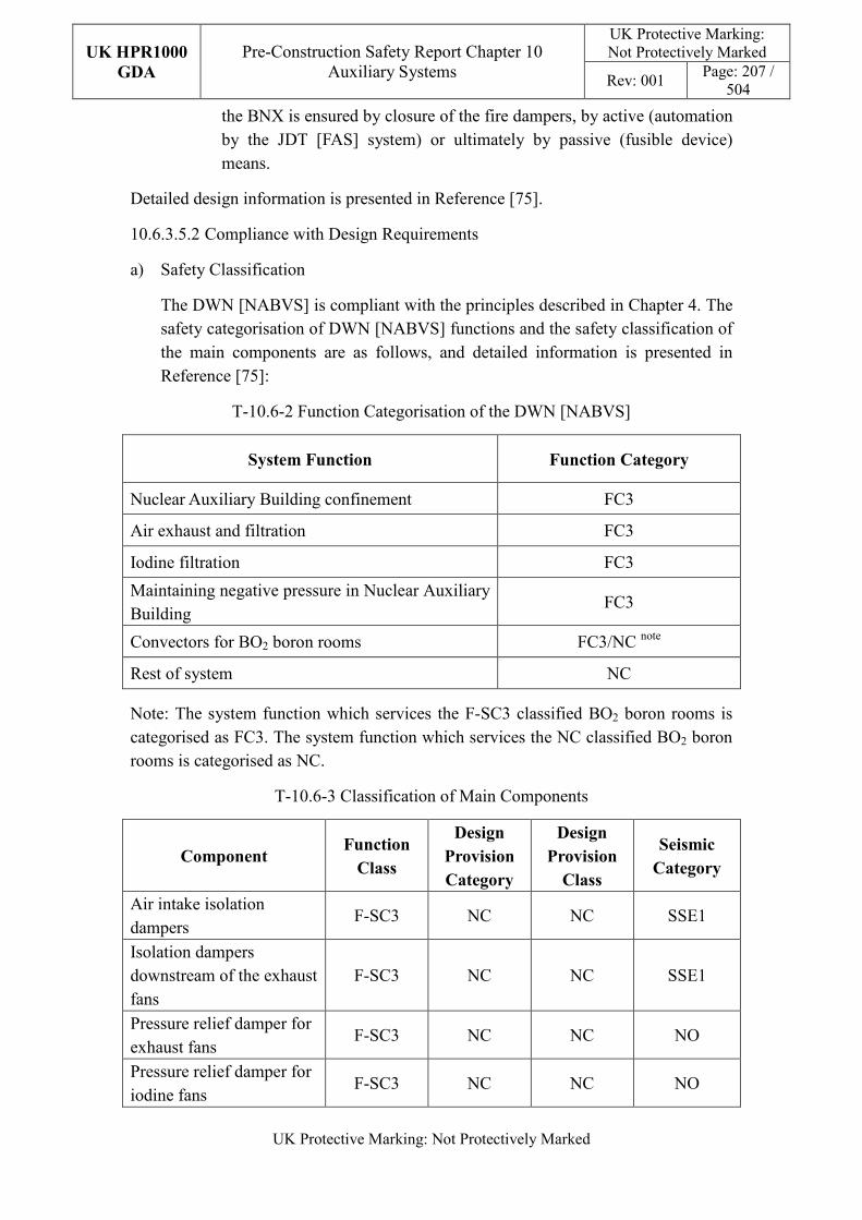
UK HPR1000
GDA
Pre-Construction Safety Report Chapter 10 Auxiliary Systems
UK Protective Marking: Not Protectively Marked
Rev: 001 Page: 207 /
504
UK Protective Marking: Not Protectively Marked
the BNX is ensured by closure of the fire dampers, by active (automation by the JDT [FAS] system) or ultimately by passive (fusible device) means.
Detailed design information is presented in Reference [75].
10.6.3.5.2 Compliance with Design Requirements
a) Safety Classification
The DWN [NABVS] is compliant with the principles described in Chapter 4. The safety categorisation of DWN [NABVS] functions and the safety classification of the main components are as follows, and detailed information is presented in Reference [75]:
T-10.6-2 Function Categorisation of the DWN [NABVS]
System Function Function Category
Nuclear Auxiliary Building confinement FC3
Air exhaust and filtration FC3
Iodine filtration FC3
Maintaining negative pressure in Nuclear Auxiliary Building
FC3
Convectors for BO2 boron rooms FC3/NC note
Rest of system NC
Note: The system function which services the F-SC3 classified BO2 boron rooms is categorised as FC3. The system function which services the NC classified BO2 boron rooms is categorised as NC.
T-10.6-3 Classification of Main Components
Component Function
Class
Design
Provision
Category
Design
Provision
Class
Seismic
Category
Air intake isolation dampers
F-SC3 NC NC SSE1
Isolation dampers downstream of the exhaust fans
F-SC3 NC NC SSE1
Pressure relief damper for exhaust fans
F-SC3 NC NC NO
Pressure relief damper for iodine fans
F-SC3 NC NC NO
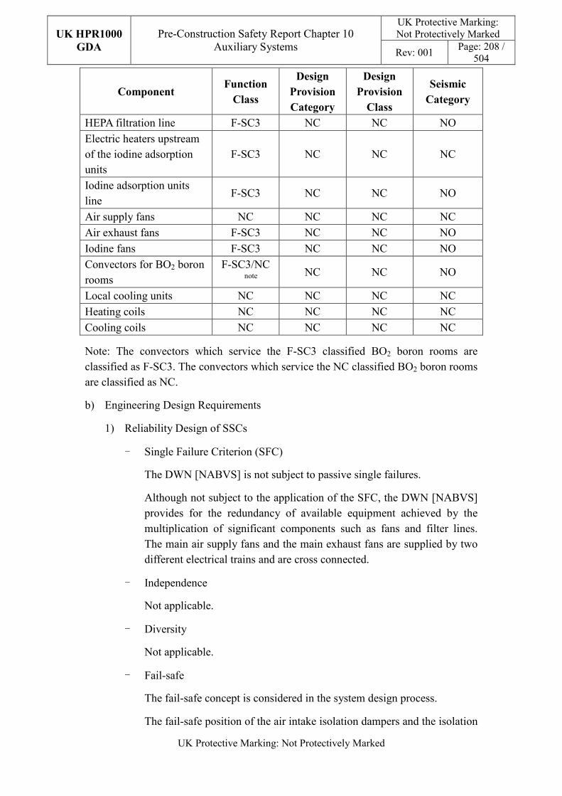
UK HPR1000
GDA
Pre-Construction Safety Report Chapter 10 Auxiliary Systems
UK Protective Marking: Not Protectively Marked
Rev: 001 Page: 208 /
504
UK Protective Marking: Not Protectively Marked
Component Function
Class
Design
Provision
Category
Design
Provision
Class
Seismic
Category
HEPA filtration line F-SC3 NC NC NO
Electric heaters upstream of the iodine adsorption units
F-SC3 NC NC NC
Iodine adsorption units line
F-SC3 NC NC NO
Air supply fans NC NC NC NC
Air exhaust fans F-SC3 NC NC NO
Iodine fans F-SC3 NC NC NO
Convectors for BO2 boron rooms
F-SC3/NC note
NC NC NO
Local cooling units NC NC NC NC
Heating coils NC NC NC NC
Cooling coils NC NC NC NC
Note: The convectors which service the F-SC3 classified BO2 boron rooms are classified as F-SC3. The convectors which service the NC classified BO2 boron rooms are classified as NC.
b) Engineering Design Requirements
1) Reliability Design of SSCs
- Single Failure Criterion (SFC)
The DWN [NABVS] is not subject to passive single failures.
Although not subject to the application of the SFC, the DWN [NABVS] provides for the redundancy of available equipment achieved by the multiplication of significant components such as fans and filter lines. The main air supply fans and the main exhaust fans are supplied by two different electrical trains and are cross connected.
- Independence
Not applicable.
- Diversity
Not applicable.
- Fail-safe
The fail-safe concept is considered in the system design process.
The fail-safe position of the air intake isolation dampers and the isolation
UK HPR1000
GDA
Pre-Construction Safety Report Chapter 10 Auxiliary Systems
UK Protective Marking: Not Protectively Marked
Rev: 001 Page: 209 /
504
UK Protective Marking: Not Protectively Marked
dampers downstream the air supply fans is the closed position.
- Ageing and Degradation
The plant design life is 60 years. Some components are required to be replacing at the end of their individual design life. The performance of equipment is guaranteed through life examination, inspection, maintenance and testing, as well as the monitoring during normal operation, which can ensure that ageing effects do not compromise safety performance.
2) Human Factors
The system design of the DWN [NABVS] does not require short term operator intervention; however there are operator actions during plant normal operation, of which the effect needs to be estimated.
The DWN [NABVS] air supply and exhaust fans are centrally arranged so that they can be easily accessed. The DWN [NABVS] is controlled and monitored in the main control room. It is designed to be convenient for the operators to control.
3) Autonomy
- Autonomy in Respect of Operators
The design principles relevant to the autonomy in respect of operators are not applicable for DWN [NABVS] design.
- Autonomy in Respect of the Heat Sink
The design principles relevant to the autonomy in respect of the heat sink are not applicable for DWN [NABVS] design.
- Autonomy in Respect of Power Supply Systems
The design principles relevant to the autonomy in respect of the power supply are not applicable for DWN [NABVS] design.
4) Other Design Requirements
- Prevention of Harmful Interactions of Systems Important to Safety
Not applicable.
- Considerations Related to the Electrical Power Grid
The functionality of items important to safety in the DWN [NABVS] is not compromised by disturbances in the electrical power grid. Detailed design information of the electrical power grid is presented in Reference [71].
UK HPR1000
GDA
Pre-Construction Safety Report Chapter 10 Auxiliary Systems
UK Protective Marking: Not Protectively Marked
Rev: 001 Page: 210 /
504
UK Protective Marking: Not Protectively Marked
c) Equipment Qualification
The air intake isolation dampers and exhaust check back dampers of the DWN [NABVS] shall be qualified in accordance with SSE1.
Principles of equipment qualification classification of the system are presented in Reference [75]. Detailed information related to the system equipment qualification is presented in Reference [71].
d) Protection against Internal and External Hazards
The HVAC systems comply with the requirements of external and internal hazards stated in Sub-chapter 10.2.4, for ventilation system, the corresponding protection measures of earthquake and internal fire are described as below.
1) External hazards
- Earthquake
The DWN [NABVS] system components are seismically qualified to confirm that their stability/integrity is ensured following a seismic event.
These air intake isolation dampers and exhaust check back dampers of DWN [NABVS] which ensure isolation of air entry and exhaust in the nuclear auxiliary building in case of earthquake shall be qualified in accordance with SSE1.
2) Internal hazards
- Internal Fire
The fire rating of the duct is same as the fire barrier when it passes through the barrier, if not, fire dampers are equipped in the duct. The fire rating of the duct is achieved by fireproof wrap.
A temperature sensor is arranged after each iodine adsorber. The fire dampers arranged upstream and downstream of the iodine adsorbers can be closed automatically and the affected booster fans shut down in case of fire detection.
Specific protection measures of other hazards are presented in Reference [73]
e) Commissioning
Commissioning and tests shall be carried out to validate the system’s functionality. The methodology of system commissioning programme design is presented in Reference [31]. Further detailed site specific arrangements for the UK HPR1000 commissioning activities will be presented during the nuclear site licencing phase in conjunction with the site licensee.
UK HPR1000
GDA
Pre-Construction Safety Report Chapter 10 Auxiliary Systems
UK Protective Marking: Not Protectively Marked
Rev: 001 Page: 211 /
504
UK Protective Marking: Not Protectively Marked
f) Examination, Inspection, Maintenance and Testing
1) Examination and Inspection
There is no equipment of the DWN [NABVS] requiring in-service inspection.
The following functions of the DWN [NABVS] are monitored during normal operation by continuous monitoring:
- Temperature of air supply in the main ventilation lines;
- The exhaust air for any traces of iodine, on detection of which the system activates the iodine adsorption lines;
- The negative pressure in the controlled area of the BNX to guarantee dynamic confinement.
2) Maintenances
Generally, scheduled maintenance is carried out preferentially during periods when the EBA [CSBVS] is not in use (and therefore the overall DWN [NABVS] airflow is reduced).
The maintenance of supply and exhaust air fans can be performed during plant power operation as well as during plant shut down since these components are designed with a 4×50% capacity.
The 4 iodine booster fans are normally in standby during plant power operation. The maintenance can be performed during this period. In case of maintenance activities suddenly being required in one system, 3 iodine booster fans remain available.
3) Periodic Tests
The safety-classified parts of the DWN [NABVS] are subject to periodic tests:
- closing of the building isolation dampers in the supply and exhaust line;
- efficiency of HEPA filters;
- correct operation of the extraction fans;
- switchover to the iodine adsorption lines;
- efficiency of the iodine adsorption units.
For the UK HPR1000, the periodic test design method is presented in the Reference [32].
g) Decommissioning

UK HPR1000
GDA
Pre-Construction Safety Report Chapter 10 Auxiliary Systems
UK Protective Marking: Not Protectively Marked
Rev: 001 Page: 212 /
504
UK Protective Marking: Not Protectively Marked
Decommissioning considerations are taken into account of system design. The principles are given in SDM chapter 3, Reference [75].
h) Material Selection
1) The main distribution and exhaust air ducts are made out of concrete with a de-contaminable finish.
2) Other supply and exhaust air ducts are made out of galvanised metal sheet.
3) Airtight exhaust air ducts are made out of carbon steel welded with a finish that can be decontaminated.
4) The exhaust duct section from the laboratory to the concrete duct is made out of austenitic stainless steel.
5) Components up to the first heater on the supply line are resistant against saline environments.
6) Pipework connected to the atmospheric buffer tank and the outside are resistant against saline environments.
10.6.3.6 Simplified Diagrams
The simplified system diagram is presented in Figure F-10.6-1; the detailed system functional diagrams are presented in Reference [76].
10.6.4 Fuel Building Ventilation System (DWK [FBVS])
The DWK [FBVS] provides appropriate environmental conditions and confinement of radioactive material in the BFX. Information of the system is presented in the SDM chapter 2, Reference [78].
10.6.4.1 Safety Functional Requirements
10.6.4.1.1 Control of Reactivity
The DWK [FBVS] does not contribute to this safety function.
10.6.4.1.2 Removal of Heat
The DWK [FBVS] does not contribute to this safety function.
10.6.4.1.3 Confinement
The DWK [FBVS] contributes to the confinement of radioactive substances:
a) Environmental Protection:
1) contain the radioactive material and prevent the risk of leaks;
2) limit radioactive discharges into the environment through treatment and control of the waste conveyed.
UK HPR1000
GDA
Pre-Construction Safety Report Chapter 10 Auxiliary Systems
UK Protective Marking: Not Protectively Marked
Rev: 001 Page: 213 /
504
UK Protective Marking: Not Protectively Marked
b) Limiting Radiological Consequences:
1) Dynamic Confinement
Not applicable.
2) Static Isolation
- In the event of a fuel handling accident in the BFX (DBC-4), the DWK [FBVS] automatically isolates the normal air supply and extraction of the fuel pool hall.
- In the event of a fuel handling accident in the BRX (DBC-4), the DWK [FBVS] automatically isolates the air supply of the room adjacent to the emergency airlock.
- In the event of failure of the two main cooling trains of the pool (DEC-A), the DWK [FBVS] automatically isolates the normal air supply and extraction of the fuel pool hall.
- Emergency extraction is required in the event of fuel pool boiling in order to maintain the long-term confinement of the BFX and to limit the pressure in the fuel pool hall in DEC-A and DEC-B conditions.
3) Purification
Not applicable.
10.6.4.1.4 Extra Safety Functions
With respect to its contribution to the extra functions, the DWK [FBVS] must satisfy the following requirements:
a) Supporting the Fundamental Safety Functions
The DWK [FBVS] provides the environmental conditions required for the safety classified equipment under normal operating and accident conditions in the BFX.
b) Prevent, Protect and Mitigate Hazards Impact
Fire: Control and limit the spread of fire in the BFX.
10.6.4.2 Design Requirements
The general design requirements of the HVAC systems which need to be considered are shown in Sub-chapter 10.2.4, among which the following requirements are not applicable for the DWK [FBVS]:
a) Autonomy in Respect of Heat Sink
Not applicable, because the DWK [FBVS] doesn’t provide a heat sink to the power plant.
UK HPR1000
GDA
Pre-Construction Safety Report Chapter 10 Auxiliary Systems
UK Protective Marking: Not Protectively Marked
Rev: 001 Page: 214 /
504
UK Protective Marking: Not Protectively Marked
b) Autonomy in Respect of Power Supply Systems
Not applicable, because the DWK [FBVS] doesn’t provide a power supply system to the power plant.
c) Prevention of Harmful Interactions of Systems Important to Safety
Not applicable, because the DWK [FBVS] doesn’t have harmful interactions of systems important to safety.
The substantiation analysis of the DWK [FBVS] to other design requirements is shown in the Sub-chapter 10.6.4.5.2.
10.6.4.3 Design Bases
10.6.4.3.1 General Assumptions
The DWK [FBVS] air supply and extraction are provided by the DWN [NABVS].
Redundant isolation dampers are used to ensure the static confinement of the fuel pool hall, BFX and the room adjacent to the emergency airlock during accident conditions.
Local cooling units are used to remove the heat loads and to ensure the correct operation for the RBS [EBS] / RCV [CVCS] /PTR [FPCTS] pump rooms.
Redundant electrical heaters are used to maintain the minimum required temperature in all boron rooms.
10.6.4.3.2 Design Assumptions
a) Control of Reactivity
Not applicable. The DWK [FBVS] does not contribute to the safety function of control of reactivity.
b) Removal of Heat
Not applicable. The DWK [FBVS] system does not contribute to the safety function of removal of heat.
c) Confinement
1) Environmental Protection:
Maintain a negative pressure in the controlled area of the BFX relative to the atmosphere.
Limit radioactive discharges into the environment through treatment of the DWN [NABVS].
2) Limiting Radiological Consequences:
- Dynamic Confinement
UK HPR1000
GDA
Pre-Construction Safety Report Chapter 10 Auxiliary Systems
UK Protective Marking: Not Protectively Marked
Rev: 001 Page: 215 /
504
UK Protective Marking: Not Protectively Marked
Not applicable.
- Static Isolation
In order to isolate the fuel pool hall, the DWK [FBVS] isolation dampers located on the air supply / extraction system of the fuel pool hall must be closed quickly. These isolation dampers are reinforced to be leak tight, and the leakage rates shall meet the requirement defined in Table T-10.6-38.
In order to isolate the room adjacent to the emergency airlock, the DWK [FBVS] isolation dampers located on the air supply / extraction system of the room adjacent to the emergency airlock must be closed quickly. These isolation dampers are reinforced to be leak tight, and the leakage rates shall meet the requirement defined in Table T-10.6-38.
In order to isolate the BFX, the DWK [FBVS] isolation dampers located on the air supply / extraction system of the BFX must be closed quickly. These isolation dampers are reinforced to be leak tight, and the leakage rates shall meet the requirement defined in Table T-10.6-38.
In the BFX fuel pool hall, the rupture disk internal opening pressure is set at {******* *}.
- Purification
Not applicable.
d) Extra Safety Functions
1) Supporting the Fundamental Safety Functions
- The external conditions to be taken into account for the DWK [FBVS] are defined in Table T-10.6-41.
- The internal room conditions to be taken into account for the DWK [FBVS] are defined in Table T-10.6-44.
- Cooling of the RBS [EBS] / RCV [CVCS] /PTR [FPCTS] pump rooms.
- The DWK [FBVS] local cooling units have been sized taking into account the following assumptions:
• Heat loads dissipated by equipment and pipework in fault conditions;
• Loss of general ventilation.
- Heating of the RBS [EBS] boron rooms
2) Prevent, Protect and Mitigate Hazards Impact
UK HPR1000
GDA
Pre-Construction Safety Report Chapter 10 Auxiliary Systems
UK Protective Marking: Not Protectively Marked
Rev: 001 Page: 216 /
504
UK Protective Marking: Not Protectively Marked
- Fire
The fire dampers must be closed automatically when air temperature is
higher than 70℃.
e) Other Assumptions
1) Minimum Air Renewal Rate
The minimum air renewal rate in a room depends on the radiation zone and potential pollutants in the room are defined in Table T-10.6-45.
2) Cooling of the APG [SGBS] Pipe Rooms and PTR [FPCTS] Purifying Pumps Rooms.
The DWK [FBVS] local cooling units have been sized taking into account the following assumptions:
- heat loads dissipated by equipment and pipework under normal conditions;
- internal room conditions are defined in Table T-10.6-43.
10.6.4.4 System Description and Operation
10.6.4.4.1 System Description
a) General System Description
The DWK [FBVS] is composed of one set of an air supply duct network and one set of an extraction duct network. The air supply and extraction duct network connects with the main air supply and extraction duct network of the Nuclear Auxiliary Building Ventilation System (DWN [NABVS]).
The summary of the main components are as follows:
1) Two supply air inlets with isolation dampers and control dampers;
2) Two extraction air outlets with isolation dampers;
3) Convectors which maintain the temperature in boron rooms;
4) Local cooling units which maintain the temperature in equipment rooms with large heat release;
5) Ducts for air supply and extraction of fuel pool hall with isolation dampers;
6) Ducts for air supply and extraction of emergency airlock with isolation dampers;
7) Fan air heaters which maintain the conditions in the fuel pool hall.
Detailed information of the systems is presented in the SDM, Reference [77].
UK HPR1000
GDA
Pre-Construction Safety Report Chapter 10 Auxiliary Systems
UK Protective Marking: Not Protectively Marked
Rev: 001 Page: 217 /
504
UK Protective Marking: Not Protectively Marked
b) Description of Main Equipment
1) Electrical Heaters
The electrical heaters are designed to maintain minimum temperatures in the boron rooms to avoid boron crystallization. They are made of copper tubes with several passes depending on the thermal characteristics.
2) Fan Air Heaters
The fan air heaters are designed to heat the air in the fuel pool hall. A fan air heater consists of a fan and an electrical heater.
3) Local Cooling Units
The local cooling units are designed to provide cooling to the air. A local cooling unit consists of a fan and a cooling coil supplied with chilled water.
4) Isolation Dampers
The isolation dampers are designed to ensure the isolation of the air supply and extraction of in the fuel pool hall, the fuel building and the room adjacent to the emergency airlock.
Detailed information of the equipment design is presented in the SDM chapter 4, Reference [77].
c) Description of Main Layout
The DWK [FBVS] main equipment is located in fuel building. The local cooling units are located in corresponding pump rooms.
Detailed design information about the system layout is presented in the SDM, Reference [79].
d) Description of System Interface
1) DWN [NABVS]
During normal conditions, it provides supply air to DWK [FBVS] and receives the exhaust air.
2) DEL [SCWS]
The DEL [SCWS] supplies chilled water to the local cooling units in the RBS [EBS] pump rooms, RCV [CVCS] pump rooms and the PTR [FPCTS] pump rooms.
3) DER [OCWS]
The DER [OCWS] supplies chilled water to the local cooling units of the PTR purification and skimming pump rooms and the APG [SGBS] pipe
UK HPR1000
GDA
Pre-Construction Safety Report Chapter 10 Auxiliary Systems
UK Protective Marking: Not Protectively Marked
Rev: 001 Page: 218 /
504
UK Protective Marking: Not Protectively Marked
rooms.
4) JDT [FAS]
The Fire Alarm System (JDT [FAS]) provides signals to control the fire dampers of the DWK [FBVS].
5) RPE [VDS]
The Nuclear Island Vent and Drain System (RPE [VDS]) collects drainage water from the DWK [FBVS] local cooling units.
6) DWL [SBCAVS]
The Safeguard Building Controlled Area Ventilation System (DWL [SBCAVS] provides the extraction for the pool hall in the event of a fuel handing accident.
7) EBA [CSBVS]
The Containment Sweeping and Blowndown Ventilation System (EBA [CSBVS]) provides the extraction for the fuel building in the event of a fuel handling accident in the BRX.
Detailed information of the interface systems is presented in the SDM, Reference [77].
e) Description of Instrumentation and Control
Instruments controlling and monitoring of the DWK [FBVS], and displaying of the actuator of the DWK [FBVS] are presented in the MCR.
10.6.4.4.2 System Operation
a) Plant Normal Conditions
The DWK [FBVS] operates continuously, to maintain the following functions:
1) Ensure ambient conditions for the normal operation of equipment and personnel work through the DWN [NABVS];
2) Maintain a negative pressure in the fuel building compared to the atmosphere;
3) Ensure that contamination is contained at source to avoid its spreading from potentially contaminated areas to potentially less contaminated areas;
4) Reduce the concentration of aerosols and radioactive gases in the control area.
b) Plant Accident Conditions
UK HPR1000
GDA
Pre-Construction Safety Report Chapter 10 Auxiliary Systems
UK Protective Marking: Not Protectively Marked
Rev: 001 Page: 219 /
504
UK Protective Marking: Not Protectively Marked
1) During a fuel handling accident (DBC-4) in fuel building, the air supply and extraction system of fuel pool hall is automatically isolated and dynamic confinement of fuel pool hall is enforced by the DWL [SBCAVS] extraction and filtration system.
2) During a fuel handling accident (DBC-4) in the reactor building, the DWK [FBVS] automatically isolate the extraction in front of the emergency airlock.
3) In case the two main trains of the PTR [FPCTS] fail (DEC-A), the air supply and extraction system of fuel pool hall is automatically isolated to ensure static containment of fuel pool hall.
4) In the event of a LOCA (DBC-3/DBC-4), static confinement of the fuel building is achieved by closing the isolation dampers located at the air supply and at the extraction of the normal ventilation of the fuel building. Moreover, the dynamic confinement (by the EBA [CSBVS] system) of the fuel building ensures collection and filtering before the release of any leak from the reactor building to the fuel building.
5) In the event of LOOP, the local cooling units of the RBS [EBS], RCV [CVCS] and PTR [FPCTS] pump rooms, the boric heaters and the electrical fan heaters in the pool hall are supplied by the emergency diesel generators.
6) In the event of an SBO (DEC-A), static confinement of the fuel building is achieved: the isolation dampers located at the air supply and at the extraction of the normal ventilation of the fuel building have a fail-safe closed position in the event of a loss of the power supply.
7) In the event of Severe Accident (SA), the fuel building achieves dynamic confinement when the EBA [CSBVS] extraction system receives a SI signal.
Detailed information of the system operation is presented in the SDM, Reference [77].
10.6.4.5 Preliminary Design Substantiation
In this sub-chapter, the system design is demonstrated to satisfy the safety functional requirements presented in Sub-chapter 10.6.4.1 and the general design requirements stated in Sub-chapter 10.2.4. Review of the consistency of the system design against the principles is currently being undertaken.
10.6.4.5.1 Compliance with Safety Functional Requirements
a) Control of Reactivity
Not applicable.
b) Removal of Heat
Not applicable.
UK HPR1000
GDA
Pre-Construction Safety Report Chapter 10 Auxiliary Systems
UK Protective Marking: Not Protectively Marked
Rev: 001 Page: 220 /
504
UK Protective Marking: Not Protectively Marked
c) Confinement
1) Environmental Protection:
The DWK [FBVS] ductwork and other HVAC system components are reinforced so as to reduce the risk of mechanical failures and protect the environment against potential radioactive leaks. Moreover, in order to limit potential radioactive discharges into the environment under normal operation, extracted air is filtered by the DWN [NABVS] before discharging it to the main unit ventilation stack.
A motorised control damper on the DWK [FBVS] supply line of each division is used to control the supply flow rate and maintain a negative pressure of 100 Pa in the controlled area.
2) Limiting Radiological Consequences:
- Dynamic confinement
Not applicable.
- Static isolation
In order to isolate the fuel pool hall, redundant quick closing isolation dampers (on supply and exhaust lines) are closed on receipt of a KRT [PRMS] system signal. These isolation dampers are reinforced to be leak tight, and the leakage rates shall meet the requirement defined in Table T-10.6-38.
In order to isolate the room adjacent to the emergency airlock, redundant quick closing isolation dampers (on supply and exhaust lines) are closed on receipt of a KRT [PRMS] system signal. These isolation dampers are reinforced to be leak tight, and the leakage rates shall meet the requirement defined in Table T-10.6-38.
In order to isolate the BFX, redundant quick closing isolation dampers (on supply and exhaust lines) are closed on receipt of a SI signal. These isolation dampers are reinforced to be leak tight, and the leakage rates shall meet the requirement defined in Table T-10.6-38.
In the fuel pool hall, the rupture disk pressure of the qualified overpressure protection device installed in the fuel pool area is set at {******* *}.
d) Extra Safety Functions
1) Supporting the Fundamental Safety Functions
The DWK [FBVS] for the sizing of local cooling units enable room (RBS
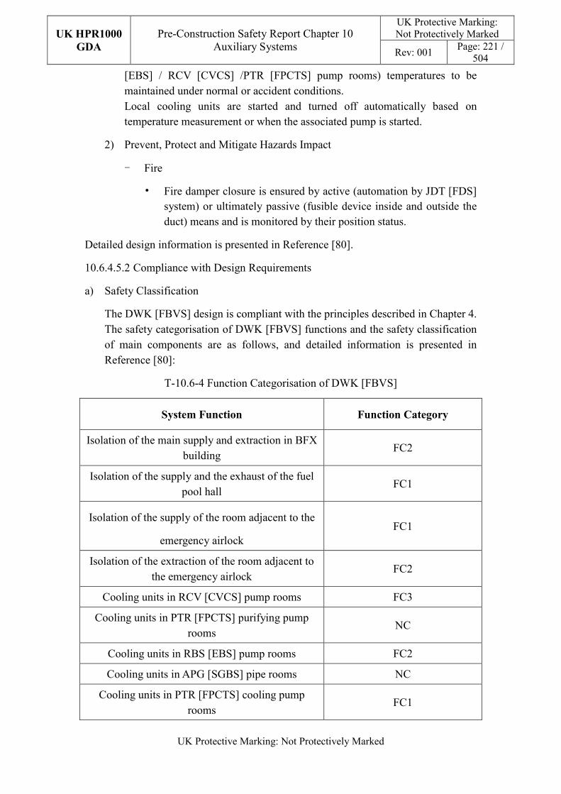
UK HPR1000
GDA
Pre-Construction Safety Report Chapter 10 Auxiliary Systems
UK Protective Marking: Not Protectively Marked
Rev: 001 Page: 221 /
504
UK Protective Marking: Not Protectively Marked
[EBS] / RCV [CVCS] /PTR [FPCTS] pump rooms) temperatures to be maintained under normal or accident conditions. Local cooling units are started and turned off automatically based on temperature measurement or when the associated pump is started.
2) Prevent, Protect and Mitigate Hazards Impact
- Fire
• Fire damper closure is ensured by active (automation by JDT [FDS] system) or ultimately passive (fusible device inside and outside the duct) means and is monitored by their position status.
Detailed design information is presented in Reference [80].
10.6.4.5.2 Compliance with Design Requirements
a) Safety Classification
The DWK [FBVS] design is compliant with the principles described in Chapter 4. The safety categorisation of DWK [FBVS] functions and the safety classification of main components are as follows, and detailed information is presented in Reference [80]:
T-10.6-4 Function Categorisation of DWK [FBVS]
System Function Function Category
Isolation of the main supply and extraction in BFX building
FC2
Isolation of the supply and the exhaust of the fuel pool hall
FC1
Isolation of the supply of the room adjacent to the
emergency airlock FC1
Isolation of the extraction of the room adjacent to the emergency airlock
FC2
Cooling units in RCV [CVCS] pump rooms FC3
Cooling units in PTR [FPCTS] purifying pump rooms
NC
Cooling units in RBS [EBS] pump rooms FC2
Cooling units in APG [SGBS] pipe rooms NC
Cooling units in PTR [FPCTS] cooling pump rooms
FC1
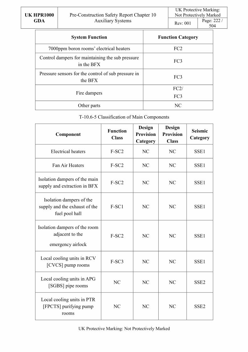
UK HPR1000
GDA
Pre-Construction Safety Report Chapter 10 Auxiliary Systems
UK Protective Marking: Not Protectively Marked
Rev: 001 Page: 222 /
504
UK Protective Marking: Not Protectively Marked
System Function Function Category
7000ppm boron rooms’ electrical heaters FC2
Control dampers for maintaining the sub pressure in the BFX
FC3
Pressure sensors for the control of sub pressure in the BFX
FC3
Fire dampers FC2/
FC3
Other parts NC
T-10.6-5 Classification of Main Components
Component Function
Class
Design
Provision
Category
Design
Provision
Class
Seismic
Category
Electrical heaters F-SC2 NC NC SSE1
Fan Air Heaters F-SC2 NC NC SSE1
Isolation dampers of the main supply and extraction in BFX
F-SC2 NC NC SSE1
Isolation dampers of the supply and the exhaust of the
fuel pool hall F-SC1 NC NC SSE1
Isolation dampers of the room adjacent to the
emergency airlock
F-SC2 NC NC SSE1
Local cooling units in RCV [CVCS] pump rooms
F-SC3 NC NC SSE1
Local cooling units in APG [SGBS] pipe rooms
NC NC NC SSE2
Local cooling units in PTR [FPCTS] purifying pump
rooms NC NC NC SSE2
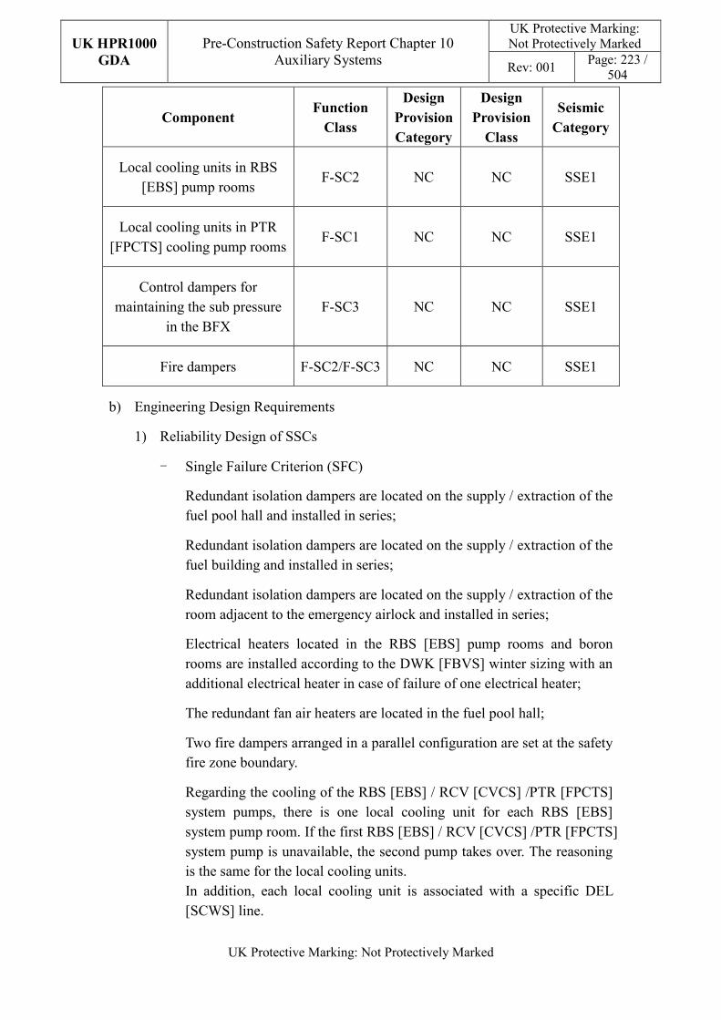
UK HPR1000
GDA
Pre-Construction Safety Report Chapter 10 Auxiliary Systems
UK Protective Marking: Not Protectively Marked
Rev: 001 Page: 223 /
504
UK Protective Marking: Not Protectively Marked
Component Function
Class
Design
Provision
Category
Design
Provision
Class
Seismic
Category
Local cooling units in RBS [EBS] pump rooms
F-SC2 NC NC SSE1
Local cooling units in PTR [FPCTS] cooling pump rooms
F-SC1 NC NC SSE1
Control dampers for maintaining the sub pressure
in the BFX F-SC3 NC NC SSE1
Fire dampers F-SC2/F-SC3 NC NC SSE1
b) Engineering Design Requirements
1) Reliability Design of SSCs
- Single Failure Criterion (SFC)
Redundant isolation dampers are located on the supply / extraction of the fuel pool hall and installed in series;
Redundant isolation dampers are located on the supply / extraction of the fuel building and installed in series;
Redundant isolation dampers are located on the supply / extraction of the room adjacent to the emergency airlock and installed in series;
Electrical heaters located in the RBS [EBS] pump rooms and boron rooms are installed according to the DWK [FBVS] winter sizing with an additional electrical heater in case of failure of one electrical heater;
The redundant fan air heaters are located in the fuel pool hall;
Two fire dampers arranged in a parallel configuration are set at the safety fire zone boundary.
Regarding the cooling of the RBS [EBS] / RCV [CVCS] /PTR [FPCTS] system pumps, there is one local cooling unit for each RBS [EBS] system pump room. If the first RBS [EBS] / RCV [CVCS] /PTR [FPCTS] system pump is unavailable, the second pump takes over. The reasoning is the same for the local cooling units. In addition, each local cooling unit is associated with a specific DEL [SCWS] line.
UK HPR1000
GDA
Pre-Construction Safety Report Chapter 10 Auxiliary Systems
UK Protective Marking: Not Protectively Marked
Rev: 001 Page: 224 /
504
UK Protective Marking: Not Protectively Marked
- Independence
The different trains of local cooling units of the RBS [EBS] / RCV [CVCS] /PTR [FPCTS] pump rooms are located in separated rooms.
- Diversity
The weakness of HVAC diversity design will be identified in Justification of the diversification of HVAC systems report. And a preliminary design of the diverse HVAC systems will be provided. Detailed diversity modification of HVAC systems will be finished in step 4.
- Fail-safe
The fail-safe concept is considered in the system design process.
The DWK [FBVS] static confinement isolation dampers have a fail-safe closed position in the event of a loss of the power supply.
- Ageing and Degradation
The plant design life is 60 years. Some components need replacing at the end of their individual design life.
2) Human Factors
The system design of the DWK [FBVS] does not require short term operator intervention, however there are operator actions during plant normal operation, the effect of which needs to be estimated. The main equipment is located in the fuel building, where they are facilitated for the simplicity of applicable maintenance procedures. The DWK [FBVS] is controlled and monitored in the MCR. It is designed to be convenient for the operators to control.
3) Autonomy
- Autonomy in Respect of Operators
The design principles relevant to the autonomy in respect of operators are detailed in Sub-chapter 10.2.4. The design of the DWK [FBVS] fulfils these principles via control functional design; detailed information is presented in the SDM, Reference [81]. The design result is estimated in the safety analysis.
- Autonomy in Respect of the Heat Sink
The design principles relevant to the autonomy in respect of the heat sink are not applicable for the DWK [FBVS] design.
UK HPR1000
GDA
Pre-Construction Safety Report Chapter 10 Auxiliary Systems
UK Protective Marking: Not Protectively Marked
Rev: 001 Page: 225 /
504
UK Protective Marking: Not Protectively Marked
- Autonomy in Respect of Power Supply Systems
The design principles relevant to the autonomy in respect of the power supply are not applicable for the DWK [FBVS] design.
4) Other Design Requirements
- Prevention of Harmful Interactions of Systems Important to Safety
Not applicable.
- Considerations Related to the Electrical Power Grid
The functionality of items important to safety in the DWK [FBVS] is not compromised by disturbances in the electrical power grid. Detailed design information of the electrical power grid is presented in Reference [77].
c) Equipment Qualification
All the components of the DWK [FBVS] required for performing safety functions are capable of operating under both normal and accident conditions. As a result, the components can withstand the most adverse environmental conditions expected.
All the seismically classified components of the DWK [FBVS] shall be capable of operating during and after the SSE. The components are seismically designed and qualified for the SSE loads.
Principles of equipment qualification classification of the system are presented in Reference [80]. Detailed information related to the system equipment qualification is presented in Reference [77].
d) Protection against Internal and External Hazards
The HVAC systems comply with the requirements of external and internal hazards stated in Sub-chapter 10.2.4, for ventilation system, the corresponding protection measures of earthquake and internal fire are described as below.
1) External hazards
- Earthquake
The seismic category for the components of the DWK [FBVS] performing Safety Category 1 (FC1) and Safety Category 2 (FC2) is Seismic Category 1 (SSE1).
The seismic class for the components performing Safety Category 3 (FC3) classified functions are Seismic Category 2 (SSE2).
2) Internal hazards
UK HPR1000
GDA
Pre-Construction Safety Report Chapter 10 Auxiliary Systems
UK Protective Marking: Not Protectively Marked
Rev: 001 Page: 226 /
504
UK Protective Marking: Not Protectively Marked
- Internal Fire
The fire rating of the duct is same as the fire barrier when it passes through the barrier, if not, fire dampers are equipped in the duct. The fire rating of the duct is achieved by fireproof wrap.
Specific protection measures of other hazards are presented in Reference [79].
e) Commissioning
Commissioning and tests shall be carried out to validate the system’s functionality. The methodology of system commissioning programme design is presented in Reference [31]. Further detailed site specific arrangements for the UK HPR1000 commissioning activities will be presented during the nuclear site licencing phase in conjunction with the site licensee.
f) Examination, Inspection, Maintenance and Testing
1) Examination and Inspection
There is no equipment of the DWK [FBVS] which requires in-service inspection.
The combined information of the DWK [FBVS] displayed in the MCR for the operator includes:
- Temperature of boron rooms;
- Temperature of rooms served by local cooling units;
- Temperature of fuel pool hall.
2) Maintenances
During normal operation conditions, the DWK [FBVS] operates continuously.
Maintenance of local cooling units could be performed when the corresponding train serving users are in maintenance during shutdown of the plant.
3) Periodic Tests
FC1, FC2 and FC3 equipment should be tested if they are not in continuous operation. Some equipment performing safety functions shall be subject to periodic testing, mainly including operability of local cooling units.
For the UK HPR1000, the periodic test design method is presented in the Reference [32].
g) Decommissioning
UK HPR1000
GDA
Pre-Construction Safety Report Chapter 10 Auxiliary Systems
UK Protective Marking: Not Protectively Marked
Rev: 001 Page: 227 /
504
UK Protective Marking: Not Protectively Marked
Decommissioning considerations are taken into account of system design. The principles are given in SDM chapter 3, Reference [80].
h) Material Selection
The material of the duct is galvanised steel sheet except for the fuel pool hall and the emergency airlock.
The material of ducts in the fuel pool and the emergency airlock is carbon steel.
10.6.4.6 Simplified Diagrams
The simplified system diagram is presented in Figure F-10.6-2; the detailed system functional diagrams are presented in Reference [82].
10.6.5 Containment Cooling and Ventilation System (EVR [CCVS])
The EVR [CCVS] is designed to maintain the required ambient conditions for the normal operation of the equipment in the reactor building, to facilitate personnel access, to cool the Control Rod Drive Mechanism (CRDM), to cool the reactor pit and to provide ventilation for the dome. Information of the system is presented in the SDM chapter 2, Reference [84].
10.6.5.1 Safety Functional Requirements
10.6.5.1.1 Control of Reactivity
The EVR [CCVS] does not contribute to this safety function.
10.6.5.1.2 Removal of Heat
The EVR [CCVS] does not contribute to this safety function.
10.6.5.1.3 Confinement
The EVR [CCVS] does not contribute to this safety function.
10.6.5.1.4 Extra Safety Functions
With respect to its contribution to the extra safety functions, the EVR [CCVS] must satisfy the following requirements:
a) Supporting the Fundamental Safety Functions
The safety function for the EVR [CCVS] is reactor pit cooling during SBO.
b) Prevent, Protect and Mitigate Hazards Impact
Not applicable.
10.6.5.2 Design Requirements
The general design requirements of the HVAC systems which need to be considered
UK HPR1000
GDA
Pre-Construction Safety Report Chapter 10 Auxiliary Systems
UK Protective Marking: Not Protectively Marked
Rev: 001 Page: 228 /
504
UK Protective Marking: Not Protectively Marked
are shown in Sub-chapter 10.2.4, among which the following requirements are not applicable for the EVR [CCVS]:
a) Autonomy in Respect of Operators
Not applicable, because the EVR [CCVS] doesn’t contribute to the autonomy objective.
b) Autonomy in Respect of the Heat Sink
Not applicable, because the EVR [CCVS] doesn’t provide a heat sink to the power plant.
c) Autonomy in Respect of Power Supply Systems
Not applicable, because the EVR [CCVS] doesn’t provide a power supply to the power plant.
d) Prevention of Harmful Interactions of Systems Important to Safety
Not applicable, because the EVR [CCVS] doesn’t have harmful interactions of systems important to safety.
The substantiation analysis of the EVR [CCVS] to other design requirements is shown in the Sub-chapter 10.6.5.5.2.
10.6.5.3 Design Bases
10.6.5.3.1 General Assumptions
The main ventilation subsystem: 4×50% fans and air conditioning units;
The reactor pit ventilation subsystem: 4×50% fans;
The CRDM ventilation subsystem: 4×50% fan and cooling coils;
The dome ventilation subsystem: 2×100% fans.
10.6.5.3.2 Design Assumptions
a) Control of Reactivity
Not applicable. The EVR [CCVS] does not contribute to the safety function of control of reactivity.
b) Removal of Heat
Not applicable. The EVR [CCVS] does not contribute to the safety function of removal of heat.
c) Confinement
Not applicable. There’s no quantitative safety-related design assumption for the
UK HPR1000
GDA
Pre-Construction Safety Report Chapter 10 Auxiliary Systems
UK Protective Marking: Not Protectively Marked
Rev: 001 Page: 229 /
504
UK Protective Marking: Not Protectively Marked
EVR [CCVS].
d) Extra Safety Functions
1) Supporting the Fundamental Safety Functions
The internal room condition to be taken into account for the EVR [CCVS] is defined in Table T-10.6-43.
2) Prevent, Protect and Mitigate Hazards Impact
Not applicable.
e) Other Assumptions
The supply air temperature of the main ventilation subsystem is assumed to be 18°C.
The capacity of the air conditioning unit is determined by the maximum heat dissipation of the equipment and pipes under normal conditions.
The internal room condition to be taken into account for the EVR [CCVS] is defined in Table T-10.6-43.
10.6.5.4 System Description and Operation
10.6.5.4.1 System Description
a) General System Description
The EVR [CCVS] consists of a main circulation ventilation subsystem, reactor pit air supply subsystem, dome circulating ventilation subsystem and control rod drive mechanism ventilation subsystem. These subsystems are composed of components as follows:
1) Main circulating ventilation subsystem: 4×50% fans and air conditioning units;
2) Reactor pit air supply subsystem: 4×50% fans;
3) Ventilation subsystem of the CRDM area: 4×50% fans, 4×50% cooling coils;
4) Dome circulating ventilation subsystem: 2×100% circulating fans.
Detailed information of the systems is presented in the SDM, Reference [83].
b) Description of Main Equipment
1) Fans
The main ventilation fans are designed to provide circulating ventilation for the containment. Reactor pit fans are designed to provide air supply to the reactor pit. CRDM ventilation fans are designed to provide ventilation for the
UK HPR1000
GDA
Pre-Construction Safety Report Chapter 10 Auxiliary Systems
UK Protective Marking: Not Protectively Marked
Rev: 001 Page: 230 /
504
UK Protective Marking: Not Protectively Marked
CRDM. Dome fans are designed to provide exhaust for the dome. CRDM ventilation fans are a centrifugal and direct-coupled drive type. The other fans are axial.
2) Cooling coils
The cooling coils are designed to cool the air, they are made of copper tubes with copper or aluminium fins. The frames are made of stainless steel.
3) Air conditioning units
The air conditioning units are designed to cool the air. An air conditioning unit is equipped with two cooling coils and two cooling coils installed on both sides of the air conditioning cabinet.
Detailed information of the equipment design is presented in the SDM chapter 4, Reference [83].
c) Description of Main Layout
The EVR [CCVS] main equipment is located in the containment of the reactor building. The fans of the reactor pit ventilation subsystem are arranged in the special ventilated room.
Detailed design information about the system layout is presented in the SDM, Reference [85].
d) Description of System Interface
The EVR [CCVS] is connected to the following mechanical systems (not including power supplies and I&C systems):
1) DER [OCWS]
This system is used to provide chilled water for the cooling coil of the main air supply subsystem of the EVR [CCVS].
2) RRI [CCWS]
This system is used to provide cooling water for the cooling coil of the CRDM cooling ventilation subsystem.
3) EBA [CSBVS]
This system is used to send fresh air from the DWN [NABVS] to the main annular duct of the EVR [CCVS], to then send the air to all rooms through the duct network.
4) RPE [VDS]
This system is used to collect condensate from cooling coils of the EVR
UK HPR1000
GDA
Pre-Construction Safety Report Chapter 10 Auxiliary Systems
UK Protective Marking: Not Protectively Marked
Rev: 001 Page: 231 /
504
UK Protective Marking: Not Protectively Marked
[CCVS].
5) REN [NSS]
This system is used for nuclear sampling of the air in the air supply duct of the EVR [CCVS].
Detailed information of the interface systems is presented in the SDM, Reference [83].
e) Description of Instrumentation and Control
Instruments controlling and monitoring the EVR [CCVS], and displaying of the actuator are presented in the Main Control Room.
Detailed information of the system I&C design is presented in the SDM, Reference [86].
10.6.5.4.2 System Operation
a) Plant Normal Conditions
During plant operation at normal power and normal shutdown with heat removal, the EVR [CCVS] continuously operates to maintain the necessary environmental conditions.
During cold shutdown of the plant, the EVR [CCVS] is out of service. Based on the environmental temperature in containment, one or two main fans of the EVR [CCVS] or another ventilation subsystem can be activated.
b) Plant Accident Conditions
1) Loss of Offsite Power (LOOP)
All the subsystems of the EVR [CCVS] are powered by the emergency diesel generators and the ventilation system continuously operates.
2) Fuel handling accident in containment
If the EVR [CCVS] is available, it can be activated as needed to discharge the released heat.
3) Station Black Out (SBO)
Only the fans of the reactor pit air supply subsystem are powered by SBO diesel generators.
Detailed information of the system operation is presented in the SDM, Reference [86].
10.6.5.5 Preliminary Design Substantiation
In this sub-chapter, the system design is demonstrated to satisfy the safety functional requirements presented in Sub-chapter 10.6.5.1 and the general design requirements
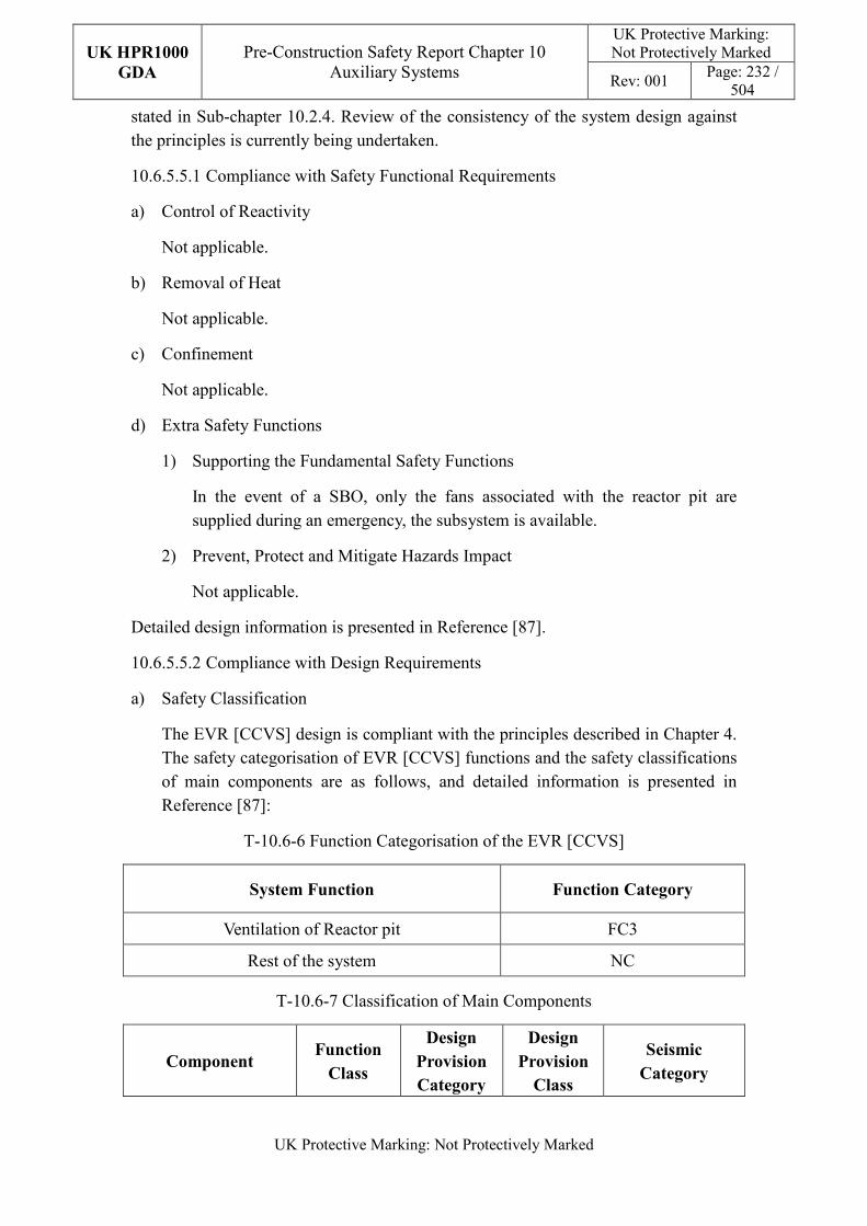
UK HPR1000
GDA
Pre-Construction Safety Report Chapter 10 Auxiliary Systems
UK Protective Marking: Not Protectively Marked
Rev: 001 Page: 232 /
504
UK Protective Marking: Not Protectively Marked
stated in Sub-chapter 10.2.4. Review of the consistency of the system design against the principles is currently being undertaken.
10.6.5.5.1 Compliance with Safety Functional Requirements
a) Control of Reactivity
Not applicable.
b) Removal of Heat
Not applicable.
c) Confinement
Not applicable.
d) Extra Safety Functions
1) Supporting the Fundamental Safety Functions
In the event of a SBO, only the fans associated with the reactor pit are supplied during an emergency, the subsystem is available.
2) Prevent, Protect and Mitigate Hazards Impact
Not applicable.
Detailed design information is presented in Reference [87].
10.6.5.5.2 Compliance with Design Requirements
a) Safety Classification
The EVR [CCVS] design is compliant with the principles described in Chapter 4. The safety categorisation of EVR [CCVS] functions and the safety classifications of main components are as follows, and detailed information is presented in Reference [87]:
T-10.6-6 Function Categorisation of the EVR [CCVS]
System Function Function Category
Ventilation of Reactor pit FC3
Rest of the system NC
T-10.6-7 Classification of Main Components
Component Function
Class
Design
Provision
Category
Design
Provision
Class
Seismic
Category
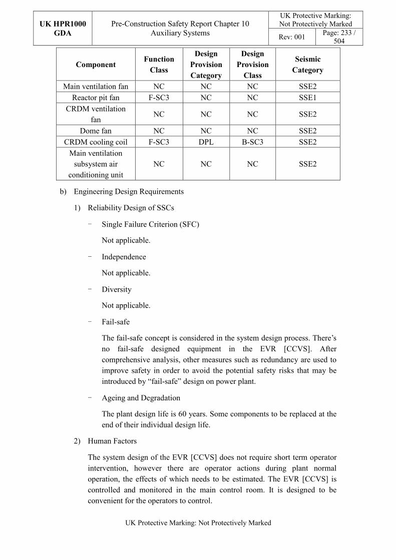
UK HPR1000
GDA
Pre-Construction Safety Report Chapter 10 Auxiliary Systems
UK Protective Marking: Not Protectively Marked
Rev: 001 Page: 233 /
504
UK Protective Marking: Not Protectively Marked
Component Function
Class
Design
Provision
Category
Design
Provision
Class
Seismic
Category
Main ventilation fan NC NC NC SSE2
Reactor pit fan F-SC3 NC NC SSE1
CRDM ventilation fan
NC NC NC SSE2
Dome fan NC NC NC SSE2
CRDM cooling coil F-SC3 DPL B-SC3 SSE2
Main ventilation subsystem air
conditioning unit NC NC NC SSE2
b) Engineering Design Requirements
1) Reliability Design of SSCs
- Single Failure Criterion (SFC)
Not applicable.
- Independence
Not applicable.
- Diversity
Not applicable.
- Fail-safe
The fail-safe concept is considered in the system design process. There’s no fail-safe designed equipment in the EVR [CCVS]. After comprehensive analysis, other measures such as redundancy are used to improve safety in order to avoid the potential safety risks that may be introduced by “fail-safe” design on power plant.
- Ageing and Degradation
The plant design life is 60 years. Some components to be replaced at the end of their individual design life.
2) Human Factors
The system design of the EVR [CCVS] does not require short term operator intervention, however there are operator actions during plant normal operation, the effects of which needs to be estimated. The EVR [CCVS] is controlled and monitored in the main control room. It is designed to be convenient for the operators to control.
UK HPR1000
GDA
Pre-Construction Safety Report Chapter 10 Auxiliary Systems
UK Protective Marking: Not Protectively Marked
Rev: 001 Page: 234 /
504
UK Protective Marking: Not Protectively Marked
3) Autonomy
- Autonomy in Respect of Operators
The design principles relevant to the autonomy in respect of operators are not applicable for EVR [CCVS] design.
- Autonomy in Respect of the Heat Sink
The design principles relevant to the autonomy in respect of the heat sink are not applicable for EVR [CCVS] design.
- Autonomy in Respect of Power Supply Systems
The design principles relevant to the autonomy in respect of the power supply are not applicable for EVR [CCVS] design.
4) Other Design Requirements
- Prevention of Harmful Interactions of Systems Important to Safety
Not applicable.
- Considerations Related to the Electrical Power Grid
The functionality of items important to safety in the EVR [CCVS] is not compromised by disturbances in the electrical power grid. Detailed design information of the electrical power grid is presented in Reference [83].
c) Equipment Qualification
All the components of the EVR [CCVS] required performing safety functions are capable of operating under both normal and accident conditions. As a result, the components can withstand the most adverse environmental conditions expected.
All the seismically classified components of the EVR [CCVS] shall be capable of operating during and after the SSE. The components are seismically designed and qualified for the SSE loads.
Principles of equipment qualification classification of the system are presented in Reference [87]. Detailed information related to the system equipment qualification is presented in Reference [83].
d) Protection Design against Internal and External Hazards
The HVAC systems comply with the requirements of external and internal hazards stated in Sub-chapter 10.2.4, for ventilation system, the corresponding protection measures of earthquake and internal fire are described as below.
1) External hazards
UK HPR1000
GDA
Pre-Construction Safety Report Chapter 10 Auxiliary Systems
UK Protective Marking: Not Protectively Marked
Rev: 001 Page: 235 /
504
UK Protective Marking: Not Protectively Marked
- Earthquake
The seismic category for the components of the reactor pit ventilation subsystem is SSE1 level. Considering the earthquake does not affect the SSE1 level equipment in the BRX, the rest equipment of EVR [CCVS] is SSE2.
2) Internal hazards
- Internal Fire
The fire rating of the duct is same as the fire barrier when it passes through the barrier, if not, fire dampers are equipped in the duct. The fire rating of the duct is achieved by fireproof wrap.
Specific protection measures of other hazards are presented in Reference [85].
e) Commissioning
Commissioning and tests shall be carried out to validate the system’s functionality. The methodology of system commissioning programme design is presented in Reference [31]. Further detailed site specific arrangements for the UK HPR1000 commissioning activities will be presented during the nuclear site licencing phase in conjunction with the site licensee.
f) Examination, Inspection, Maintenance and Testing
1) Examination and Inspection
There is no equipment of the EVR [CCVS] requiring in-service inspection.
The combined information of the EVR [CCVS] displayed in the Main Control Room (MCR) for the operator includes:
- Temperature of supply and exhaust air;
- Flow of exhaust air;
- Temperature of rooms;
- Differential pressure of fans;
- Temperature of fan motor bearings.
2) Maintenances
During normal operating conditions, the EVR [CCVS] operates continuously. Maintenance of the main components can be performed during shutdown of the plant.
3) Periodic Tests
UK HPR1000
GDA
Pre-Construction Safety Report Chapter 10 Auxiliary Systems
UK Protective Marking: Not Protectively Marked
Rev: 001 Page: 236 /
504
UK Protective Marking: Not Protectively Marked
For the UK HPR1000, the periodic test design method is presented in the Reference [32].
FC1, FC2 and FC3 equipment should be tested if they are not in continuous operation. Some equipment performing safety functions shall be subject to periodic testing, mainly including:
- Switchover between the operating and backup train;
- Checking of room temperatures.
g) Decommissioning
Decommissioning considerations are taken into account of system design. The principles are given in SDM chapter 3, Reference [87].
h) Material Selection
Stainless steel air ducts are preferred in the reactor building.
10.6.5.6 Simplified Diagrams
The simplified system diagram is presented in Figure F-10.6-3; the detailed system functional diagrams are presented in Reference [88].
10.6.6 Containment Internal Filtration System (EVF [CIFS])
During normal plant operation, the Containment Internal Filtration System (EVF [CIFS]) operates non-continuously in order to reduce the concentration of radioactive substances and aerosols in the containment. Information of the system is presented in the SDM chapter 2, Reference [90].
10.6.6.1 Safety Functional Requirements
10.6.6.1.1 Control of Reactivity
The EVF [CIFS] does not contribute to this safety function.
10.6.6.1.2 Removal of Heat
The EVF [CIFS] does not contribute to this safety function.
10.6.6.1.3 Confinement
The EVF [CIFS] does not contribute to this safety function.
10.6.6.1.4 Extra Safety Functions
With respect to its contribution to the extra functions, the EVF [CIFS] must satisfy the following requirements:
a) Supporting the Fundamental Safety Functions
UK HPR1000
GDA
Pre-Construction Safety Report Chapter 10 Auxiliary Systems
UK Protective Marking: Not Protectively Marked
Rev: 001 Page: 237 /
504
UK Protective Marking: Not Protectively Marked
The EVF [CIFS] does not contribute to supporting the fundamental safety functions.
b) Prevent, Protect and Mitigate Hazards Impact
Fire: The fire dampers must be closed automatically when air temperature is
higher than 70℃.
10.6.6.2 Design Requirements
The general design requirements of the HVAC systems which need to be considered are shown in Sub-chapter 10.2.4, among which the following requirements are not applicable for the EVF [CIFS]:
a) Autonomy in Respect of the Heat Sink
Not applicable, because the EVF [CIFS] doesn’t provide a heat sink to the power plant.
b) Autonomy in Respect of Power Supply Systems
Not applicable, because EVF [CIFS] doesn’t provide a power supply to the power plant.
c) Prevention of Harmful Interactions of Systems Important to Safety.
Not applicable, because the EVF [CIFS] doesn’t have harmful interactions of systems important to safety.
The substantiation analysis of the EVF [CIFS] to other design requirements is shown in the Sub-chapter 10.6.6.5.2.
10.6.6.3 Design Bases
10.6.6.3.1 General Assumptions
a) 1×100% iodine adsorption train;
b) 2×100% exhaust fans.
10.6.6.3.2 Design Assumptions
a) Control of Reactivity
Not applicable. The EVF [CIFS] does not contribute to the safety function of control of reactivity.
b) Removal of Heat
Not applicable. The EVF [CIFS] does not contribute to the safety function of removal of heat.
c) Confinement
UK HPR1000
GDA
Pre-Construction Safety Report Chapter 10 Auxiliary Systems
UK Protective Marking: Not Protectively Marked
Rev: 001 Page: 238 /
504
UK Protective Marking: Not Protectively Marked
Not applicable. The EVF [CIFS] does not contribute to the safety function of confinement.
d) Extra Safety Functions
1) Supporting the Fundamental Safety Functions
Not applicable. The EVF [CIFS] does not contribute to supporting the fundamental safety functions.
2) Prevent, Protect and Mitigate Hazards Impact
Fire: The fire dampers must be closed automatically when air temperature is
higher than 70℃.
e) Other Assumptions
1) The internal room conditions of non-safety functional rooms for the EVF [CIFS] are defined in Table T-10.6-43;
2) The external conditions to be taken into account for the EVF [CIFS] are defined in Table T-10.6-42;
3) For the filtration efficiency of HEPA filters and iodine adsorber see Tables T-10.6-39 and T-10.6-40;
4) Maintain the relative humidity of the iodine adsorber inlet below 70%;
5) Electric heater inlet environments is 40°C at 100% relative humidity.
10.6.6.4 System Description and Operation
10.6.6.4.1 System Description
a) General System Description
The EVF [CIFS] includes a 1×100% iodine adsorption train, which consists of:
1) 1×100% iodine adsorption train (including an electric heater, pre-filter, HEPA filter and iodine adsorber);
2) 2×100% exhaust fans;
3) Dampers, duct network and a set of accessories.
Detailed information of the systems is presented in the SDM, Reference [89].
b) Description of Main Equipment
1) Fans
The fans are a centrifugal and direct-coupled drive type.
2) Electrical Heaters
UK HPR1000
GDA
Pre-Construction Safety Report Chapter 10 Auxiliary Systems
UK Protective Marking: Not Protectively Marked
Rev: 001 Page: 239 /
504
UK Protective Marking: Not Protectively Marked
The electric heaters are designed to maintain the relative humidity of the iodine adsorber inlet by heating the air, and they are comprised of reinforced tubular elements placed in a sheet metal box.
3) Pre-filters
The pre-filters are designed to filter dust in the air. Their efficiency is more than 85% (weighting method).
4) HEPA Filters
The HEPA filters are designed to filter dust in the air. Each HEPA filter cell is individually factory tested to verify an efficiency of at least 99.99%, corresponding to a 10000 filtering factor (sodium flame method).
5) Iodine Adsorbers
The iodine adsorbers are designed to remove radioactive iodine suspended in the air, each adsorber is assembly with a welded construction and a 102mm deep Type III rechargeable adsorber cell. When new, these filters have a filtering factor of at least 1000 (methyl iodide).
Detailed information of the equipment design is presented in the SDM chapter 4, Reference [89].
c) Description of Main Layout
The EVF [CIFS] is located in the reactor building.
Detailed design information about the system layout is presented in the SDM, Reference [91].
d) Description of System Interface
The EVF [CIFS] is connected to the following mechanical systems (not including power supplies and I&C systems):
1) EVR [CCVS])
Containment Cooling and Ventilation System (EVR [CCVS]) supplies the mixing of the contaminated air.
2) JDT [FAS]
Fire Alarm System (JDT [FAS]) which can detect a fire in the iodine adsorbers, then in response closes the fire dampers and sets off an alarm in the control room.
3) JPI [NIFPS]
In the event of a fire in the charcoal filter of the iodine adsorption units, the
UK HPR1000
GDA
Pre-Construction Safety Report Chapter 10 Auxiliary Systems
UK Protective Marking: Not Protectively Marked
Rev: 001 Page: 240 /
504
UK Protective Marking: Not Protectively Marked
Fire-fighting Water System for Nuclear Island (JPI [NIFPS]) can be manually activated to provide a water spray to extinguish the fire.
4) KRT [PRMS]
The Plant Radiation Monitoring System (KRT [PRMS]) which detects high activity in reactor building and triggers the automatic operation of the EVF [CIFS].
Detailed information of the interface systems is presented in the SDM, Reference [89].
e) Description of Instrumentation and Control
Instrumentation controlling and monitoring the EVF [CIFS] and displaying of the actuator are provided in the Main Control Room.
Detailed information of the system I&C design is presented in the SDM, Reference [92].
10.6.6.4.2 System Operation
a) Plant Normal Conditions
During power operation and hot shutdown, the EVF [CIFS] operates to purge the reactor building if necessary.
b) Plant Accident Conditions
The EVF [CIFS] is not required during plant accident conditions.
Detailed information of the system operation is presented in the SDM, Reference [92].
10.6.6.5 Preliminary Design Substantiation
In this sub-chapter, the system design is demonstrated to satisfy the safety functional requirements presented in Sub-chapter 10.6.6.1 and the general design requirements stated in Sub-chapter 10.2.4. Review of the consistency of the system design against the newly developed principles is currently being undertaken.
10.6.6.5.1 Compliance with Safety Functional Requirements
a) Control of Reactivity
Not applicable.
b) Removal of Heat
Not applicable.
c) Confinement
Not applicable.
UK HPR1000
GDA
Pre-Construction Safety Report Chapter 10 Auxiliary Systems
UK Protective Marking: Not Protectively Marked
Rev: 001 Page: 241 /
504
UK Protective Marking: Not Protectively Marked
d) Extra Safety Functions
1) Supporting the Fundamental Safety Functions
Not applicable. The EVF [CIFS] does not contribute to supporting the fundamental safety functions.
2) Prevent, Protect and Mitigate Hazards Impact
Fire: Fire dampers are designed on the boundary of the fire compartment, which can be closed by a JDT [FAS] signal or damper fuse in case of a fire.
Detailed design information is presented in Reference [93].
10.6.6.5.2 Compliance with Design Requirements
a) Safety Classification
The EVF [CIFS] design is compliant with the principles described in Chapter 4. The safety categorisation of EVF [CIFS] functions and the safety classification of main components are as follows, and detailed information is presented in Reference [93]:
T-10.6-8 Function Categorisation of the EVF [CIFS]
System Function Function Category
Fire dampers FC3
Rest of the system NC
T-10.6-9 Classification of Main Components
Component Function
Class
Design
Provision
Category
Design
Provision
Class
Seismic
Category
Fire dampers F-SC3 NC NC SSE1
Rest of the system NC NC NC SSE2
b) Engineering Design Requirements
1) Reliability Design of SSCs
- Single Failure Criterion (SFC)
Since the EVF [CIFS] does not perform FC1 or FC2 safety functions, the SFC is not applicable, however 2×100% redundancy is considered for
UK HPR1000
GDA
Pre-Construction Safety Report Chapter 10 Auxiliary Systems
UK Protective Marking: Not Protectively Marked
Rev: 001 Page: 242 /
504
UK Protective Marking: Not Protectively Marked
the exhaust fans.
- Independence
Not applicable.
- Diversity
Not applicable.
- Fail-safe
The fail-safe concept is considered in the system design process.
After comprehensive analysis, other measures such as redundancy are used to improve safety in order to avoid the potential safety risks that may be introduced by “fail-safe” design on power plant.
- Ageing and Degradation
The plant design life is 60 years. Some components to be replaced at the end of their individual design life.
2) Human Factors
The system design of the EVF [CIFS] does not require short term operator intervention, however there are operator actions during plant normal operation, the effect of which needs to be estimated. The EVF [CIFS] is controlled and monitored in the main control room. It is designed to be convenient for the operators to control.
3) Autonomy
- Autonomy in Respect of Operators
The design principles relevant to the autonomy in respect of operators are detailed in Sub-chapter 10.2.4. The design of the EVF [CIFS] fulfils these principles via control functional design; detailed information is presented in the SDM, Reference [92]. The design result is estimated in the safety analysis.
- Autonomy in Respect of the Heat Sink
The design principles relevant to the autonomy in respect of the heat sink are not applicable for EVF [CIFS] design.
- Autonomy in Respect of Power Supply Systems
The design principles relevant to the autonomy in respect of the power supply are not applicable for EVF [CIFS] design.
4) Other Design Requirements
UK HPR1000
GDA
Pre-Construction Safety Report Chapter 10 Auxiliary Systems
UK Protective Marking: Not Protectively Marked
Rev: 001 Page: 243 /
504
UK Protective Marking: Not Protectively Marked
- Prevention of Harmful Interactions of Systems Important to Safety
Not applicable.
- Considerations Related to the Electrical Power Grid
The functionality of items important to safety in the EVF [CIFS] is not compromised by disturbances in the electrical power grid. Detailed design information of the electrical power grid is presented in Reference [89].
c) Equipment Qualification
All the components of the EVF [CIFS] required performing safety functions are capable of operating under both normal and accident conditions. As a result, the components can withstand the most adverse environmental conditions expected.
All the seismically classified components of the EVF [CIFS] shall be capable of operating during and after the SSE. The components are seismically designed and qualified for the SSE loads.
Principles of equipment qualification classification of the system are presented in Reference [93]. Detailed information related to the system equipment qualification is presented in Reference [89].
d) Protection Design against Internal and External Hazards
The HVAC systems comply with the requirements of external and internal hazards stated in Sub-chapter 10.2.4, for ventilation system, the corresponding protection measures of earthquake and internal fire are described as below.
1) External hazards
- Earthquake
The seismic class for the components of EVF [CIFS] performing Safety Category 3 (FC3) classified functions are Seismic Category 1 (SSE1), and the rest of EVF [CIFS] components are Seismic Category 2 (SSE2).
2) Internal hazards
- Internal Fire
The fire rating of the duct is same as the fire barrier when it passes through the barrier, if not, fire dampers are equipped in the duct. The fire rating of the duct is achieved by fireproof wrap.
Specific protection measures of other hazards are presented in Reference [91].
e) Commissioning
UK HPR1000
GDA
Pre-Construction Safety Report Chapter 10 Auxiliary Systems
UK Protective Marking: Not Protectively Marked
Rev: 001 Page: 244 /
504
UK Protective Marking: Not Protectively Marked
Commissioning and tests shall be carried out to validate the system’s functionality. The methodology of system commissioning programme design is presented in Reference [31]. Further detailed site specific arrangements for the UK HPR1000 commissioning activities will be presented during the nuclear site licencing phase in conjunction with the site licensee.
f) Examination, Inspection, Maintenance and Testing
1) Examination and Inspection
There is no equipment of the EVF [CIFS] requiring in-service inspection.
The combined information of the EVF [CIFS] displayed in the Main Control Room (MCR) for the operator includes:
- Temperature upstream and downstream of heaters;
- Position of isolated dampers;
- Position of fire dampers;
- Status of fan;
- Status of heaters.
2) Maintenances
Maintenance of the components can be done during shutdown of the plant.
3) Periodic Tests
For the UK HPR1000, the periodic test design method is presented in the Reference [32].
FC3 equipment should be tested if they are not in continuous operation. Some equipment performing safety functions shall be subject to periodic testing, mainly including the operability of fire dampers.
g) Decommissioning
Decommissioning considerations are taken into account of system design. The principles are given in SDM chapter 3, Reference [93].
h) Material Selection
Stainless steel air ducts are preferred in the reactor building.
10.6.6.6 Simplified Diagrams
The simplified system diagram is presented in Figure F-10.6-4; the detailed system functional diagram is presented in Reference [94].
UK HPR1000
GDA
Pre-Construction Safety Report Chapter 10 Auxiliary Systems
UK Protective Marking: Not Protectively Marked
Rev: 001 Page: 245 /
504
UK Protective Marking: Not Protectively Marked
10.6.7 Containment Sweeping and Blowdown Ventilation System (EBA [CSBVS])
The EBA [CSBVS] maintains the appropriate environmental conditions in the reactor building during plant shutdown and provides dynamic confinement for the fuel building under accident conditions. Information of the system is presented in the SDM chapter 2, Reference [96].
10.6.7.1 Safety Functional Requirements
10.6.7.1.1 Control of Reactivity
The EBA [CSBVS] does not contribute to this safety function.
10.6.7.1.2 Removal of Heat
The EBA [CSBVS] does not contribute to this safety function.
10.6.7.1.3 Confinement
With respect to its contribution to confinement, the EBA [CSBVS] must satisfy the following requirements:
a) Environmental Protection
1) Contain Radioactive Material
Limit the leakage of radioactive material into the environment in normal conditions.
2) Limit Discharge
When the EBA [CSBVS] low-capacity circuit operates in normal conditions, it shall limit the discharge of radioactive materials into the environment by filtration.
b) Limiting Radiological Consequences
1) Dynamic Confinement
In the case of an event involving an activity release in the containment (DBC-3, DBC-4, DEC-A, DEC-B), the exhaust of the low-capacity circuit ensures fuel building negative pressure to limit the spread of contamination, and aids the collection of any leaks from the containment penetrations.
In the event of a fuel handling accident in the reactor building or a LOCA in cold shutdown, the containment isolation valves are closed except for the exhaust of the low-capacity circuit. The exhaust of the low-capacity circuit ensures reactor building negative pressure to limit the spread of contamination.
2) Static Isolation
UK HPR1000
GDA
Pre-Construction Safety Report Chapter 10 Auxiliary Systems
UK Protective Marking: Not Protectively Marked
Rev: 001 Page: 246 /
504
UK Protective Marking: Not Protectively Marked
In the case of an event involving an activity release in the containment (DBC-3, DBC-4, DEC-A, DEC-B), the reactor building must be completely isolated by closure of the containment isolation valves.
3) Purification
Limit the discharge of radioactive materials into the environment by filtration in accident conditions.
10.6.7.1.4 Extra Safety Functions
With respect to its contribution to the extra functions, the EBA [CSBVS] must satisfy the following requirements:
a) Supporting the Fundamental Safety Functions
The EBA [CSBVS] does not contribute to supporting the fundamental safety functions.
b) Prevent, Protect and Mitigate Hazards Impact
Fire: In case of fire, the system shall limit the spread of fire and prevent damage to safety classified equipment and personnel.
10.6.7.2 Design Requirements
The general design requirements of the HVAC systems which need to be considered are shown in Sub-chapter 10.2.4, among which the following requirements are not applicable for the EBA [CSBVS]:
a) Autonomy in Respect of the Heat Sink
Not applicable, because the EBA [CSBVS] doesn’t provide a heat sink to the power plant.
b) Autonomy in Respect of Power Supply Systems
Not applicable, because the EBA [CSBVS] doesn’t a provide power supply to the power plant.
c) Prevention of Harmful Interactions of Systems Important to Safety
Not applicable, because the EBA [CSBVS] doesn’t have harmful interactions of systems important to safety.
The substantiation analysis of the EBA [CSBVS] to other design requirements is shown in the Sub-chapter 10.6.7.5.2.
UK HPR1000
GDA
Pre-Construction Safety Report Chapter 10 Auxiliary Systems
UK Protective Marking: Not Protectively Marked
Rev: 001 Page: 247 /
504
UK Protective Marking: Not Protectively Marked
10.6.7.3 Design Bases
10.6.7.3.1 General Assumptions
The normal air supply and exhaust of the EBA [CSBVS] are supplied from the DWN [NABVS].
2×100% iodine filtration trains are set to be operational under accident conditions.
10.6.7.3.2 Design Assumptions
a) Control of Reactivity
Not applicable. The EBA [CSBVS] does not contribute to the safety function of control of reactivity.
b) Removal of Heat
Not applicable. The EBA [CSBVS] does not contribute to the safety function of removal of heat.
c) Confinement
The EBA [CSBVS] is subject to the following assumptions.
1) Environmental Protection
- Contain radioactive material
The valves or dampers which are reinforced to be leak tight, are closed if necessary. The airtightness characteristics of the valves or dampers are stated in Table T-10.6-38.
- Limit discharge
� For the filtration efficiency of the HEPA filter and iodine adsorber see Tables T-10.6-39 and T-10.6-40;
� Maintain the relative humidity of the iodine adsorber inlet below 70%;
� The electric heater inlet environment is 40°C at 100%.
2) Limiting Radiological Consequences
- Dynamic confinement
� Maintain negative pressure between the fuel building and the outside environment. For the negative pressure see Table T-10.6-36;
� Maintain negative pressure between the reactor building and the outside environment, when the emergency personnel airlock is closed. For the negative pressure see Table T-10.6-36.
UK HPR1000
GDA
Pre-Construction Safety Report Chapter 10 Auxiliary Systems
UK Protective Marking: Not Protectively Marked
Rev: 001 Page: 248 /
504
UK Protective Marking: Not Protectively Marked
- Static isolation
� All of the containment isolation valves are closed. For characteristics relevant to air tightness of the valves see Table T-10.6-38.
- Purification
� For the filtration efficiency of the HEPA filter and iodine adsorber see Tables T-10.6-39 and T-10.6-40.
� Maintain the relative humidity of the iodine adsorber inlet below 70%;
� The electric heater inlet environment is 40°C at 100%.
d) Extra Safety Functions
1) Supporting the Fundamental Safety Functions
Not applicable. The EBA [CSBVS] does not contribute to supporting the fundamental safety functions.
2) Prevent, Protect and Mitigate Hazards Impact
Fire: The fire dampers must be closed automatically when air temperature is higher than 70℃.
e) Other Assumptions
1) The internal room conditions of non-safety functional rooms for the EBA [CSBVS] are defined in Table T-10.6-43.
2) The external conditions to be taken into account for the EBA [CSBVS] are defined in Table T-10.6-42.
3) During power operation, the system is to maintain a certain pressure range between the reactor building and the outside environment. For the pressure range see Table T-10.6-37.
10.6.7.4 System Description and Operation
10.6.7.4.1 System Description
a) General System Description
The EBA [CSBVS] includes the low-capacity subsystem and high-capacity subsystem.
1) The EBA [CSBVS] low-capacity subsystem consists of:
- Containment isolation valves;
UK HPR1000
GDA
Pre-Construction Safety Report Chapter 10 Auxiliary Systems
UK Protective Marking: Not Protectively Marked
Rev: 001 Page: 249 /
504
UK Protective Marking: Not Protectively Marked
- 2×100% iodine filtration trains (each train including an electric heater, pre-filter, HEPA filter, iodine adsorber and fan);
- Dampers, a duct network and a set of accessory.
2) The EBA [CSBVS] high-capacity subsystem consists of:
- Containment isolation valves;
- Dampers, a duct network and a set of accessory.
Detailed information of the systems is presented in the SDM, Reference [95].
b) Description of Main Equipment
1) Fans
The fans are designed to provide air exhaust. Centrifugal fans with direct-coupled drive are used.
2) Electrical Heaters
The electric heaters are designed to maintain the relative humidity of the iodine adsorber inlet by heating the air. They are comprised of reinforced tubular elements placed in a sheet metal box.
3) Pre-filters
The pre-filters are designed to filter dust in the air, and their efficiency is more than 85% (weighting method).
4) HEPA Filters
The HEPA filters are designed to filter dust or aerosols in the air. Each HEPA filter cell is individually factory tested to verify an efficiency of at least 99.99%, corresponding to a 10000 filtering factor (sodium flame method).
5) Iodine Adsorbers
The iodine adsorbers are designed to remove radioactive iodine suspended in the air. Each adsorber is assembly with a welded construction and a 102mm deep Type III rechargeable adsorber cell. When new, these filters have a filtering factor of at least 1000 (methyl iodide).
6) Containment Isolation Valves
The containment isolation valves are designed to close quickly and resist the accidental conditions.
Detailed information of the equipment design is presented in the SDM chapter 4, Reference [95].
UK HPR1000
GDA
Pre-Construction Safety Report Chapter 10 Auxiliary Systems
UK Protective Marking: Not Protectively Marked
Rev: 001 Page: 250 /
504
UK Protective Marking: Not Protectively Marked
c) Description of Main Layout
The equipment of the iodine adsorption trains is located in different compartments of the fuel building.
The ducts are located in the reactor building and fuel building.
Detailed design information about the system layout is presented in the SDM, Reference [97].
d) Description of System Interface
The EBA [CSBVS] is connected to the following mechanical systems (not including power supplies and I&C systems):
1) DWN [NABVS]
The DWN [NABVS] provides and conditions the EBA [CSBVS] supply of fresh air, and ensures the filtering of the EBA [CSBVS] high-capacity extraction air to the stack.
2) EPP [CLRTMS]
The Containment Leak Rate Testing and Monitoring System (EPP [CLRTMS]) recovers the leakage of the external containment isolation valves.
3) JDT [FAS]
The Fire Alarm System (JDT [FAS]) provides a fire signal to control the fire dampers of the EBA [CSBVS].
4) JPI [NIFPS]
In the event of a fire in the charcoal filter of the iodine adsorption units, the Fire-fighting Water System for Nuclear Island (JPI [NIFPS]) can be manually activated to provide a water spray to extinguish the fire.
5) KRT [PRMS]
The Plant Radiation Monitoring System (KRT [PRMS]) detects high activity in the reactor building, and contamination downstream of adsorption for severe accident management.
6) EVR [CCVS]
The Containment Cooling and Ventilation System (EVR [CCVS]), during cold shutdown, collects the fresh air supplied by the EBA [CSBVS] and then distributes it towards rooms of the reactor building.
7) RIS [SIS]
UK HPR1000
GDA
Pre-Construction Safety Report Chapter 10 Auxiliary Systems
UK Protective Marking: Not Protectively Marked
Rev: 001 Page: 251 /
504
UK Protective Marking: Not Protectively Marked
In shutdown states, the EBA [CSBVS] is used to collect the Safety Injection System (RIS [SIS]) accumulator venting.
8) RPE [VDS]
In the shutdown states, the EBA [CSBVS] is used to collect the venting from the Nuclear Island Vent and Drain System (RPE [VDS]).
Detailed information of the interface systems is presented in the SDM, Reference [95].
e) Description of Instrumentation and Control
Parameters of the controlling and monitoring of the EBA [CSBVS] and displaying of the actuator of the EBA [CSBVS] are provided in the MCR.
Detailed information of the system I&C design is presented in the SDM, Reference [98].
10.6.7.4.2 System Operation
a) Plant Normal Conditions
During power operation, the supplied or exhausted air of the EBA [CSBVS] low-capacity subsystem can be activated to control the pressure of containment.
During plant shutdown, the EBA [CSBVS] operates in blowdown mode. The EBA [CSBVS] operates continuously to provide the necessary fresh air for personnel and to maintain the required temperature and humidity of the environment.
b) Plant Accident Conditions
In case of a fuel handling accident in the reactor building or a LOCA in cold shutdown, the containment isolation valves are quickly closed except for the exhaust low-capacity circuit. The iodine filtration operates continuously to maintain dynamic confinement of the reactor building.
In case of a LOCA during power operation, all of the containment isolation valves can be closed. The iodine filtration operates continuously to maintain dynamic confinement of the fuel building.
In case of LOOP, the EBA [CSBVS] iodine trains remain available.
In case of SBO, the EBA [CSBVS] iodine trains remains available.
In case of a severe accident with a LOCA initiator, all of the containment isolation valves are closed. The iodine filtration operates continuously to maintain dynamic confinement of fuel building.
In case of a loss all diesel generators, the internal containment isolation valves are
UK HPR1000
GDA
Pre-Construction Safety Report Chapter 10 Auxiliary Systems
UK Protective Marking: Not Protectively Marked
Rev: 001 Page: 252 /
504
UK Protective Marking: Not Protectively Marked
powered by 2h batteries and the external containment isolation valves are powered by 24h batteries. These valves could be closed or confirmed to be in a closed state by operator.
Detailed information of the system operation is presented in the SDM, Reference [98].
10.6.7.5 Preliminary Design Substantiation
In this sub-chapter, the system design is demonstrated to satisfy the safety functional requirements presented in Sub-chapter 10.6.7.1 and the general design requirements stated in Sub-chapter 10.2.4. Review of the consistency of the system design against the newly developed principles is currently being undertaken.
10.6.7.5.1 Compliance with Safety Functional Requirements
a) Control of Reactivity
Not applicable.
b) Removal of Heat
Not applicable.
c) Confinement
1) Environmental Protection
- The containment isolation valves which are reinforced to be leak tight are closed during plant normal operation. For the airtightness characteristics see Table T-10.6-38.
- The HEPA filter and iodine adsorber are arranged on the iodine filter trains. For the filtration efficiency sees Tables T-10.6-39 and T-10.6-40.
- Control the relative humidity of the iodine adsorber inlet to be below 60% to ensure the filtration efficiency of the iodine adsorber.
- Determine the electric heater capacity according to the highest possible temperature and humidity at the inlet of the iodine adsorber.
- Iodine filtration train components are designed to be reinforced level leak tight. For the airtightness characteristics of the components see Table T-10.6-38.
2) Limiting Radiological Consequences
- Maintain negative pressure between the fuel building and the outside environment. For the negative pressure value see Table T-10.6-36.
- Collect leaks from containment penetrations.
- Maintain negative pressure between the reactor building and the outside
UK HPR1000
GDA
Pre-Construction Safety Report Chapter 10 Auxiliary Systems
UK Protective Marking: Not Protectively Marked
Rev: 001 Page: 253 /
504
UK Protective Marking: Not Protectively Marked
environment when the emergency personnel gate is closed. For the negative pressure value see Table T-10.6-36.
- All of the containment isolation valves are closed within 3 seconds of receiving the shutdown command.
- Containment isolation valves are reinforced to be leak tight. For airtightness characteristics of the valves see Table T-10.6-38.
- The HEPA filter and iodine adsorber are arranged on the iodine filter trains. For the filtration efficiency sees Tables T-10.6-39 and T-10.6-40.
- Control the relative humidity of the iodine adsorber inlet to be below 60% to ensure the filtration efficiency of the iodine adsorber.
- Determine the electric heater capacity according to the highest possible temperature and humidity at the inlet of the iodine adsorber.
- Iodine filtration train components are designed be leak tight. For airtightness characteristics see Table T-10.6-38.
d) Extra Safety Functions
1) Supporting the Fundamental Safety Functions
Not applicable. The EBA [CSBVS] does not contribute to supporting the fundamental safety functions.
2) Prevent, Protect and Mitigate Hazards Impact
Fire: Fire dampers can be closed by JDT [FAS] signal or a fire protection device to ensure containment of the fire and to maintain the fire compartment integrity.
Detailed design information is presented in Reference [99].
10.6.7.5.2 Compliance with Design Requirements
a) Safety Classification
The EBA [CSBVS] design is compliant with the principles described in Chapter 4. The safety categorisation of EBA [CSBVS] functions and the safety classification of main components are as follows, and detailed information is presented in Reference [99]:
T-10.6-10 Function Categorisation of the EBA [CSBVS]
System Function Function Category
Containment isolation FC1
UK HPR1000
GDA
Pre-Construction Safety Report Chapter 10 Auxiliary Systems
UK Protective Marking: Not Protectively Marked
Rev: 001 Page: 254 /
504
UK Protective Marking: Not Protectively Marked
Low-capacity extraction and iodine adsorption FC2
Dampers and valves involved in leakage removal FC2
Extraction in the reactor building FC3
Opening of the connection dampers between low-capacity extraction and the DWK [FBVS] extraction network
FC2
T-10.6-11 Classification of Main Components
Component Function
Class
Design
Provision
Category
Design
Provision
Class
Seismic
Category
Components of iodine filtration train
F-SC2 NC NC SSE1
Containment isolation valve
F-SC1 DPM B-SC2 SSE1
b) Engineering Design Requirements
1) Reliability Design of SSCs
- Single Failure Criterion (SFC)
The EBA [CSBVS] performs FC1 and FC2 safety functions. As such, the EBA [CSBVS] must be designed to consider credible single failures. The principle single failure design features for the EBA [CSBVS] are:
2×100% iodine adsorption trains are provided in the EBA [CSBVS] low-capacity circuit:
• Two containment isolation valves on each side of the reactor building;
• Two isolation valves are installed in parallel on each leak collection line;
• Two isolation dampers are installed in parallel on each connection line between the EBA [CSBVS] low-capacity extraction circuit and the DWK [FBVS] extraction network;
• Two isolation dampers are installed in series on the supply and exhaust line.
- Independence
The EBA [CSBVS] consists of two separate iodine filtration trains located in different equipment compartments that are physically isolated in the fuel building.
UK HPR1000
GDA
Pre-Construction Safety Report Chapter 10 Auxiliary Systems
UK Protective Marking: Not Protectively Marked
Rev: 001 Page: 255 /
504
UK Protective Marking: Not Protectively Marked
- Diversity
The containment isolation valves design in the system is compliant with the diversity principles. The internal containment isolation valves and the external containment isolation valves are designed and provided by different manufacturers.
- Fail-safe
The fail-safe concept is considered in the system design process.
The fail-safe position of isolation dampers/valves of the EBA [CSBVS] is in the closed position, which includes containment isolation valves and isolation dampers on the air supply or exhaust line
- Ageing and Degradation
The plant design life is 60 years. Some components to be replaced at the end of their individual design life.
2) Human Factors
The system design of the EBA [CSBVS] does not require short term operator intervention, however there are operator actions during plant normal operation, the effect of which needs to be estimated. The equipment of each EBA [CSBVS] train is located in the same room, where the layout facilitates the ease of maintenance. The [SBCAVS] is controlled and monitored in the main control room. It is designed to be convenient for the operators to control.
3) Autonomy
- Autonomy in Respect of Operators
The design principles relevant to the autonomy in respect of operators are detailed in Sub-chapter 10.2.4. The design of the EBA [CSBVS] fulfils these principles via control functional design; detailed information is presented in the SDM, Reference [98]. The design result is estimated in the safety analysis.
- Autonomy in Respect of the Heat Sink
The design principles relevant to the autonomy in respect of the heat sink are not applicable for EBA [CSBVS] design.
- Autonomy in Respect of Power Supply Systems
The design principles relevant to the autonomy in respect of the power supply are not applicable for EBA [CSBVS] design.
UK HPR1000
GDA
Pre-Construction Safety Report Chapter 10 Auxiliary Systems
UK Protective Marking: Not Protectively Marked
Rev: 001 Page: 256 /
504
UK Protective Marking: Not Protectively Marked
4) Other Design Requirements
- Prevention of Harmful Interactions of Systems Important to Safety
Not applicable.
- Considerations Related to the Electrical Power Grid
The functionality of items important to safety in the EBA [CSBVS] is not compromised by disturbances in the electrical power grid. Detailed design information of the electrical power grid is presented in Reference [95].
c) Equipment Qualification
All the components of the EBA [CSBVS] required performing safety functions are capable of operating under both normal and accident conditions. As a result, the components can withstand the most adverse environmental conditions expected.
All the seismically classified components of the EBA [CSBVS] shall be capable of operating during and after the SSE. The components are seismically designed and qualified for the SSE loads.
Principles of equipment qualification classification of the system are presented in Reference [99]. Detailed information related to the system equipment qualification is presented in Reference [95].
d) Protection Design against Internal and External Hazards
The HVAC systems comply with the requirements of external and internal hazards stated in Sub-chapter 10.2.4, for ventilation system, the corresponding protection measures of earthquake and internal fire are described as below.
1) External hazards
- Earthquake
The seismic category for the components of the EBA [CSBVS] performing Safety Category 1 (FC1) and Safety Category 2 (FC2) is Seismic Category 1 (SSE1).
The seismic class for the components performing Safety Category 3 (FC3) classified functions are Seismic Category 2 (SSE2).
2) Internal hazards
- Internal Fire
The fire rating of the duct is same as the fire barrier when it passes through the barrier, if not, fire dampers are equipped in the duct. The fire
UK HPR1000
GDA
Pre-Construction Safety Report Chapter 10 Auxiliary Systems
UK Protective Marking: Not Protectively Marked
Rev: 001 Page: 257 /
504
UK Protective Marking: Not Protectively Marked
rating of the duct is achieved by fireproof wrap.
Specific protection measures of other hazards are presented in Reference [97].
e) Commissioning
Commissioning and tests shall be carried out to validate the system’s functionality. The methodology of system commissioning programme design is presented in Reference [31]. Further detailed site specific arrangements for the UK HPR1000 commissioning activities will be presented during the nuclear site licencing phase in conjunction with the site licensee.
f) Examination, Inspection, Maintenance and Testing
1) Examination and Inspection
There is no equipment of the EBA [CSBVS] requiring in-service inspection.
The combined information of the EBA [CSBVS] displayed in the Main Control Room (MCR) for the operator includes:
- Containment isolation valve position status.
2) Maintenances
The maintenance of the EBA [CSBVS] can be performed during plant shutdown
The maintenance of iodine filtration trains and low-capacity containment isolation valves is performed during plant shutdown when there is no fuel handling operation.
3) Periodic Tests
For the UK HPR1000, the periodic test design method is presented in the Reference [32].
FC1, FC2 and FC3 equipment should be tested periodically if they are not in continuous operation. Some equipment performing safety functions shall be subject to periodic testing, mainly including the efficiency of the HEPA filters, efficiency of iodine adsorbers, and how tight the containment isolation valves are.
g) Decommissioning
Decommissioning considerations are taken into account of system design. The principles are given in SDM chapter 3, Reference [99].
h) Material Selection
Galvanise steel when they are not classified as being airtight.
UK HPR1000
GDA
Pre-Construction Safety Report Chapter 10 Auxiliary Systems
UK Protective Marking: Not Protectively Marked
Rev: 001 Page: 258 /
504
UK Protective Marking: Not Protectively Marked
Welded and painted carbon steel when they are classified as being airtight.
10.6.7.6 Simplified Diagrams
The simplified system diagram is presented in Figure F-10.6-5; the detailed system functional diagrams are presented in Reference [100].
10.6.8 Annulus Ventilation System (EDE [AVS])
The EDE [AVS] maintains an acceptable temperature and provides dynamic confinement to the annulus of the reactor building. Information of the system is presented in the SDM chapter 2, Reference [102].
10.6.8.1 Safety Functional Requirements
The requirements of the fundamental safety functions on the EDE [AVS] for the UK HPR1000 are as identified below.
10.6.8.1.1 Control of Reactivity
The EDE [AVS] does not contribute to this safety function.
10.6.8.1.2 Removal of Heat
The EDE [AVS] does not contribute to this safety function.
10.6.8.1.3 Confinement
The EDE [AVS] provides a confinement function which is described below:
a) Environmental Protection
1) Contain Radioactive Material
Confine the leakage of radioactive material into the environment in normal conditions.
2) Limit Discharge
Limit the discharge of radioactive materials into the environment by filtration in normal conditions.
b) Limiting Radiological Consequences
1) Dynamic confinement
In accident conditions, the EDE [AVS] must maintain negative pressure in the annulus to ensure the dynamic confinement of radioactive material when there is a release of radioactive material in the annulus of the reactor building.
2) Static Isolation
UK HPR1000
GDA
Pre-Construction Safety Report Chapter 10 Auxiliary Systems
UK Protective Marking: Not Protectively Marked
Rev: 001 Page: 259 /
504
UK Protective Marking: Not Protectively Marked
In accident conditions, the containment barrier must be statically isolated.
3) Purification
Limit the discharge of radioactive materials into the environment by filtration.
10.6.8.1.4 Extra Safety Functions
The extra safety functional requirements of the EDE [AVS] are identified below:
a) Supporting the Fundamental Safety Functions
Maintain the acceptable temperature for the annulus of the reactor building.
b) Prevent, Protect and Mitigate Hazards Impact
Fire: In case of fire, the EDE [AVS] contributes to limit fire spread.
10.6.8.2 Design Requirements
The general design requirements of the HVAC systems which need to be considered are shown in Sub-chapter 10.2.4, among which the following requirements are not applicable for the EDE [AVS]:
a) Autonomy in Respect of the Heat Sink
Not applicable, because EDE [AVS] doesn’t provide a heat sink to the power plant.
b) Autonomy in Respect of Power Supply Systems
Not applicable, because EDE [AVS] doesn’t provide a power supply to the power plant.
c) Prevention of Harmful Interactions of Systems Important to Safety.
Not applicable, because the EDE [AVS] doesn’t have harmful interactions of systems important to safety.
The substantiation analysis of the EDE [AVS] to other design requirements is shown in the Sub-chapter 10.6.8.5.2.
10.6.8.3 Design Bases
10.6.8.3.1 General Assumptions
EDE [AVS] consists of 1×100% operational train and 2×100% safety trains.
10.6.8.3.2 Design Assumptions
a) Control of Reactivity
Not applicable. The EDE [AVS] does not contribute to this safety function.
UK HPR1000
GDA
Pre-Construction Safety Report Chapter 10 Auxiliary Systems
UK Protective Marking: Not Protectively Marked
Rev: 001 Page: 260 /
504
UK Protective Marking: Not Protectively Marked
b) Removal of Heat
Not applicable. The EDE [AVS] does not contribute to this safety function.
c) Confinement
The EDE [AVS] system must satisfy the functional requirements as follows:
1) Environmental Protection
- Maintain negative pressure in the annulus. For the specific negative pressure see Table T-10.6-37;
- Limit the discharge of radioactive materials into the environment by filtration in normal conditions. For the filtration efficiency of the HEPA filter see Table T-10.6-39 and T-10.6-40.
2) Limiting Radiological Consequences
- Dynamic Confinement
• Maintain negative pressure in the annulus. For the specific negative pressure see Table T-10.6-37.
• Outdoor wind Speed: During DBC-2 to DEC-A or DEC-B accident conditions, the negative pressure on the reactor building external wall due to the severe outdoor wind speeds should be considered.
• Grace Period: In the event of a total loss of the power supply, the EDE [AVS] fan is shut down and the annulus pressure starts rising. The time between EDE [AVS] fan shut down and restart is referred to as the grace period. During this period, the annulus negative pressure must not reach a value higher than that set for severe accident conditions. The grace period should be considered for the safety train alignment on the batteries and to manually start the heaters and fans during total loss of the power supply conditions. The specific period is currently being undertaken.
• Leakage from the Containment: The maximum leak rate from the internal containment is assumed to be 0.3%/day (0.52MPa, 145°C) of the free volume of the internal containment.
• Internal Containment Displacement: During accident conditions, the expansion of the internal containment increases the negative pressure of the annulus. The displacement of the internal containment diameter is assumed to be {****}.
• Fan Specifications: The flow rate of the EDE [AVS] fan is sized based on the leak rate from the internal and external containment.
UK HPR1000
GDA
Pre-Construction Safety Report Chapter 10 Auxiliary Systems
UK Protective Marking: Not Protectively Marked
Rev: 001 Page: 261 /
504
UK Protective Marking: Not Protectively Marked
• The pressure of the EDE [AVS] fan is sized based on the negative pressure in the annulus and pressure drop of the EDE [AVS] ducts.
- Static Isolation
• Isolation dampers are installed to isolate the normal ventilation which improve the ventilation leak tightness. For the reinforced level airtightness requirements of the isolation dampers see Table T-10.6-38.
- Purification
• Air Filtering: For the filtration efficiency of the HEPA filter and iodine adsorber sees Table T-10.6-39 and T-10.6-40.
• Electrical Heaters: The heaters upstream of the iodine adsorber have been designed to maintain the relative humidity below 70%. The temperature inlet of the heaters is 40°C and the relative humidity is 100%.
a) Extra Safety Functions
The EDE [AVS] must satisfy the safety functional requirements identified below:
1) Supporting the Fundamental Safety Functions
- The external conditions to be taken into account for the EDE [AVS] are defined in Table T-10.6-41.
- The internal room conditions to be taken into account for the EDE [AVS] are defined in Tables T-10.6-43 and T-10.6-44.
2) Prevent, Protect and Mitigate Hazards Impact
- Fire: The fire dampers must be closed automatically when air temperature is higher than 70℃.
b) Other Assumptions
Not applicable.
10.6.8.4 System Description and Operation
10.6.8.4.1 System Description
a) General System Description
The EDE [AVS] consists of fan heaters, one operational train and 2×100% safety trains.
The Annulus Ventilation System (EDE [AVS]) consists of:
1) An operational train (1×100%) equipped with:
UK HPR1000
GDA
Pre-Construction Safety Report Chapter 10 Auxiliary Systems
UK Protective Marking: Not Protectively Marked
Rev: 001 Page: 262 /
504
UK Protective Marking: Not Protectively Marked
- Motorised isolation dampers, pre-filter, HEPA filter, exhaust fan and non-return damper.
2) Two safety trains (2×100%), which are equipped with:
- Non-return damper, electrical heater, pre-filter, HEPA filter, iodine adsorber, exhausts fan and non-return damper.
3) Fan heaters
- Fan and electrical heaters.
Detailed information of the systems is presented in the SDM, Reference [101].
b) Description of Main Equipment
1) Fans
Safety fans are of a centrifugal and direct-coupled drive type.
2) Electrical Heaters
The electrical heaters are designed to maintain the relative humidity of the iodine adsorber inlet (the supply air temperature) by heating the air. They are comprised of reinforced tubular elements placed in a sheet metal box.
3) Pre-filters
The pre-filters are designed to filter dust or aerosols in the air and their efficiency is more than 85% (weighting method).
4) HEPA Filters
The HEPA filters are designed to filter dust in the air. Each HEPA filter cell is individually factory tested to verify an efficiency of at least 99.99%, corresponding to a 10000 filtering factor (sodium flame method).
5) Iodine Adsorbers
The iodine adsorbers are designed to remove radioactive iodine suspended in the air, each adsorber is assembly with a welded construction and a 102mm deep Type III rechargeable adsorber cell. When new, these filters have a filtering factor of at least 1000 (methyl iodide).
6) Isolation Dampers
The isolation dampers are designed to ensure the isolation of air exhaust in the annulus of the reactor building.
7) Fan heaters
Fan and electrical heaters are contained in the fan heaters; they are used to
UK HPR1000
GDA
Pre-Construction Safety Report Chapter 10 Auxiliary Systems
UK Protective Marking: Not Protectively Marked
Rev: 001 Page: 263 /
504
UK Protective Marking: Not Protectively Marked
maintain the minimum temperature in the annulus.
Detailed information of the equipment design is presented in the SDM chapter 4, Reference [101].
c) Description of Main Layout
The main components of the EDE [AVS] are located in the fuel building.
The main ducts of the EDE [AVS] are located in the fuel building and annulus of the reactor building.
Detailed information can be found in the SDM, Reference [103].
d) Description of System Interfaces
The EDE [AVS] is connected to the following mechanical systems (not including power supplies and I&C systems):
1) JDT [FAS]
It detects fires in the EDE [AVS] rooms located in the fuel building. Moreover it sends an alarm signal to the supervisor in case of an iodine adsorber fire.
2) JPI [FWSNI]
In the event of a fire in the adsorber filter of the iodine adsorption units, the JPI [FWSNI] can be manually activated to provide water spray to extinguish the fire.
3) DWK [FBVS]
It provides the reference pressure used for the annulus pressure measurements. The pressure sensors are connected to the reference pressure line of the DWK [FBVS].
4) DWN [NABVS]
The interface is only with the stack of the nuclear auxiliary building.
5) EPP [CLRTMS]
It collects the leaks around the external containment valves using the negative pressure produced by the EDE [AVS].
6) KRT [PRMS]
It samples and monitors the exhaust air from the annulus.
7) RPE [VDS]
It collects the venting of the EDE [AVS] iodine adsorbers in the fuel building.
UK HPR1000
GDA
Pre-Construction Safety Report Chapter 10 Auxiliary Systems
UK Protective Marking: Not Protectively Marked
Rev: 001 Page: 264 /
504
UK Protective Marking: Not Protectively Marked
Detailed information of the interface systems is presented in the SDM, Reference [101].
e) Description of Instrumentation and Control
Instrumentation, controlling and monitoring the EDE [AVS] and displaying of the actuator are provided in the Main Control Room.
Detailed information of the system I&C design is presented in the SDM, Reference [104].
10.6.8.4.2 System Operation
a) Plant Normal Conditions
During normal operation, the operational train of the EDE [AVS] is in continuous operation in order to maintain the negative pressure of the annulus and enable the annulus to reach the initial negative pressure at the beginning of an accident. Exhaust air is filtered by the HEPA filter of the EDE [AVS] before being discharged to the vent stack.
b) Plant Accident Conditions
In the event of a DBC-2 to DBC-4 or DEC-A event with the release of radioactivity inside containment, the ventilation system switches automatically to one of the two safety trains to process leakage from the reactor building containment. In the event of a DEC-B event with the release of radioactivity inside containment, the safety trains (A or B) can be manually started by the operator. If safety train B is out of service, safety train A can be manually started by the operator.
On a containment isolation signal phase A, the operational train is automatically isolated by the motorised isolation dampers and the operational fan is stopped. The fan and the electric heater on one of the two safety trains are started, thus maintaining the minimum negative pressure required in the annulus.
10.6.8.5 Preliminary Design Substantiation
In this sub-chapter, the system design is demonstrated to satisfy the safety functional requirements presented in Sub-chapter 10.6.8.1 and the general design requirements stated in Sub-chapter 10.2.4. Review of the consistency of the system design against the newly developed principles is currently being undertaken.
10.6.8.5.1 Compliance with Safety Functional Requirements
a) Control of Reactivity
Not applicable.
b) Removal of Heat
UK HPR1000
GDA
Pre-Construction Safety Report Chapter 10 Auxiliary Systems
UK Protective Marking: Not Protectively Marked
Rev: 001 Page: 265 /
504
UK Protective Marking: Not Protectively Marked
Not applicable.
c) Confinement
1) Environmental Protection
- Requirement to confine the leakage of radioactive material into the environment in normal conditions:
• Negative pressure to be maintained in the annulus. For the negative pressure see Table T-10.6-37.
- Requirement to limit the discharge of radioactive materials into the environment by filtration in normal conditions:
• A HEPA filter is arranged on the operational train. For the filtration efficiency see Table T-10.6-39 and T-10.6-40.
2) Limiting Radiological Consequences
Dynamic confinement
- In accident conditions, the EDE [AVS] must maintain the negative pressure in the annulus to ensure the dynamic confinement of radioactive material when there is a release of radioactive material in the annulus of the reactor building.
• Maintain negative pressure in the annulus. For the specific negative pressure see Table T-10.6-37.
• The normal air exhaust can be isolated when receiving the shutdown command. The isolation dampers are reinforced for them to be leak tight. For airtightness characteristics of the isolation dampers see Table T-10.6-38.
• Ensure start-up of the safety trains.
Static Isolation
- In accident conditions, the containment barrier must be statically isolated.
• Quick closing isolation dampers on the operational train are closed when receiving the shutdown command. For reinforced level airtightness characteristics see Table T-10.6-38.
Purification
- Requirement to limit the discharge of radioactive materials into the environment by filtration.
• Sufficient filtration of the radioactive material released into the
UK HPR1000
GDA
Pre-Construction Safety Report Chapter 10 Auxiliary Systems
UK Protective Marking: Not Protectively Marked
Rev: 001 Page: 266 /
504
UK Protective Marking: Not Protectively Marked
annulus of the EDE [AVS] must be ensured in order to limit the radioactive consequences in accident conditions. The HEPA filter and iodine adsorber are arranged on the safety trains. For the filtration efficiency sees Tables T-10.6-39 and T-10.6-40.
• The sizing of the electric heater can meet the requirements of relative humidity of the iodine adsorber inlet for it to be below 70%.
d) Extra Safety Functions
1) Supporting the Fundamental Safety Functions
The EDE [AVS] components are sized to meet the acceptable temperature requirement in the annulus.
2) Prevent, Protect and Mitigate Hazards Impact
Fire: Fire dampers can be closed by the JDT [FAS] signal or a fire protection device to ensure the containment of fire and to maintain the fire compartment integrity.
Detailed design information is presented in Reference [105].
10.6.8.5.2 Compliance with Design Requirements
a) Safety Classification
The EDE [AVS] design is compliant with the principles described in Chapter 4. The safety categorisation of EDE [AVS] functions and the safety classification of main components are as follows, and detailed information is presented in Reference [105]:
T-10.6-12 Function Categorisation of the EDE [AVS]
System Function Function Category External containment penetration FC1
Iodine adsorption by the safety trains FC2 Operational train isolating FC1
Rest of the Operational train FC2 (for part in connection with the iodine
safety train B) NC (for other equipment)
Firefighting function FC3 / FC2 Heating for the annulus FC3
T-10.6-13 Classification of Main Components
Component Function Class Design
Provision Category
Design Provision
Class
Seismic Category
External containment penetration
F-SC1 NC NC SSE1
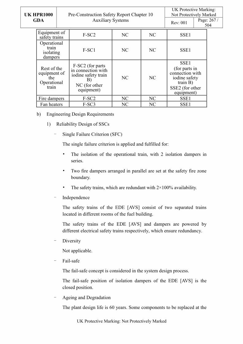
UK HPR1000
GDA
Pre-Construction Safety Report Chapter 10 Auxiliary Systems
UK Protective Marking: Not Protectively Marked
Rev: 001 Page: 267 /
504
UK Protective Marking: Not Protectively Marked
Equipment of safety trains F-SC2 NC NC SSE1
Operational train
isolating dampers
F-SC1 NC NC SSE1
Rest of the equipment of
the Operational
train
F-SC2 (for parts in connection with iodine safety train
B) NC (for other equipment)
NC NC
SSE1 (for parts in
connection with iodine safety
train B) SSE2 (for other
equipment) Fire dampers F-SC2 NC NC SSE1 Fan heaters F-SC3 NC NC SSE1
b) Engineering Design Requirements
1) Reliability Design of SSCs
- Single Failure Criterion (SFC)
The single failure criterion is applied and fulfilled for:
• The isolation of the operational train, with 2 isolation dampers in series.
• Two fire dampers arranged in parallel are set at the safety fire zone boundary.
• The safety trains, which are redundant with 2×100% availability.
- Independence
The safety trains of the EDE [AVS] consist of two separated trains located in different rooms of the fuel building.
The safety trains of the EDE [AVS] and dampers are powered by different electrical safety trains respectively, which ensure redundancy.
- Diversity
Not applicable.
- Fail-safe
The fail-safe concept is considered in the system design process.
The fail-safe position of isolation dampers of the EDE [AVS] is the closed position.
- Ageing and Degradation
The plant design life is 60 years. Some components to be replaced at the
UK HPR1000
GDA
Pre-Construction Safety Report Chapter 10 Auxiliary Systems
UK Protective Marking: Not Protectively Marked
Rev: 001 Page: 268 /
504
UK Protective Marking: Not Protectively Marked
end of their individual design life.
2) Human Factors
The system design of the EDE [AVS] does not require short term operator intervention, however there are operator actions during plant normal operation, the effect of which needs to be estimated. The main equipment of the safety trains is located in separate rooms in the fuel building, where the layout facilitates their maintenance. The EDE [AVS] is controlled and monitored in the main control room. It is designed to be convenient for the operators to control.
3) Autonomy
- Autonomy in Respect of Operators
The design principles relevant to the autonomy in respect of operators are detailed in Sub-chapter 10.2.4. The design of the EDE [AVS] fulfils these principles via control functional design; detailed information is presented in the SDM, Reference [104]. The design result is estimated in the safety analysis.
- Autonomy in Respect of the Heat Sink
The design principles relevant to the autonomy in respect of the heat sink are not applicable for EDE [AVS] design.
- Autonomy in Respect of Power Supply Systems
The design principles relevant to the autonomy in respect of the power supply are not applicable for EDE [AVS] design.
4) Other Design Requirements
- Prevention of Harmful Interactions of Systems Important to Safety
Not applicable.
- Considerations Related to the Electrical Power Grid
The functionality of items important to safety in the EDE [AVS] is not compromised by disturbances in the electrical power grid. Detailed design information of the electrical power grid is presented in Reference [101].
c) Equipment Qualification
All the components of the EDE [AVS] required performing safety functions are capable of operating under both normal and accident conditions. As a result, the components can withstand the most adverse environmental conditions expected.
UK HPR1000
GDA
Pre-Construction Safety Report Chapter 10 Auxiliary Systems
UK Protective Marking: Not Protectively Marked
Rev: 001 Page: 269 /
504
UK Protective Marking: Not Protectively Marked
All the seismically classified components of the EDE [AVS] shall be capable of operating during and after the SSE. The components are seismically designed and qualified for the SSE loads.
Principles of equipment qualification classification of the system are presented in Reference [105]. Detailed information related to the system equipment qualification is presented in Reference [101].
d) Protection against Internal and External Hazards
The HVAC systems comply with the requirements of external and internal hazards stated in Sub-chapter 10.2.4, for ventilation system, the corresponding protection measures of earthquake and internal fire are described as below.
1) External hazards
- Earthquake
The seismic category for the components of the EDE [AVS] performing Safety Category 1 (FC1) and Safety Category 2 (FC2) is Seismic Category 1 (SSE1).
2) Internal hazards
- Internal Fire
The fire rating of the duct is same as the fire barrier when it passes through the barrier, if not, fire dampers are equipped in the duct. The fire rating of the duct is achieved by fireproof wrap.
Specific protection measures of other hazards are presented in Reference [103].
e) Commissioning
Commissioning and tests shall be carried out to validate the system’s functionality. The methodology of system commissioning programme design is presented in Reference [31]. Further detailed site specific arrangements for the UK HPR1000 commissioning activities will be presented during the nuclear site licencing phase in conjunction with the site licensee.
f) Examination, Inspection, Maintenance and Testing
1) Examination and Inspection
There is no equipment of the EDE [AVS] requiring in-service inspection.
In order to ensure the correct operation of system, surveillance equipment measuring system parameters and equipment status has been designed. These measurements can help operators manage the system status at any time.
The combined information of the EDE [AVS] displayed in the MCR for the
UK HPR1000
GDA
Pre-Construction Safety Report Chapter 10 Auxiliary Systems
UK Protective Marking: Not Protectively Marked
Rev: 001 Page: 270 /
504
UK Protective Marking: Not Protectively Marked
operator includes:
- Temperature upstream and downstream of heaters;
- Position of isolated dampers;
- Position of fire dampers;
- Status of the fan;
- Status of the heater.
2) Maintenances
During normal operating conditions, the EDE [AVS] should maintain the negative pressure in the annulus. Maintenance of the components could be completed during shutdown of the plant.
The maintenance of safety trains is performed during the plant shutdown as well.
3) Periodic Tests
For the UK HPR1000, the periodic test design method is presented in the Reference [32].
FC1, FC2 and FC3 equipment should be tested if they are not in continuous operation. Some equipment performing safety functions shall be subject to periodic testing, mainly including the:
- Efficiency of HEPA filters;
- Efficiency of iodine adsorbers;
- Operation of the extraction fans and heaters;
- Operability of the motorised isolation dampers;
- Control of negative pressure.
g) Decommissioning
Decommissioning considerations are taken into account of system design. The principles are given in SDM chapter 3, Reference[105].
h) Material Selection
The extraction ducts are manufactured of carbon steel with a painted surface finish. The fireproof duct is contained within a fireproof wrap.
10.6.8.6 Simplified Diagrams
The simplified system functional diagram is presented in Figure F-10.6-6; the detailed
UK HPR1000
GDA
Pre-Construction Safety Report Chapter 10 Auxiliary Systems
UK Protective Marking: Not Protectively Marked
Rev: 001 Page: 271 /
504
UK Protective Marking: Not Protectively Marked
system functional diagram is presented in Reference [106].
10.6.9 Safeguard Building Controlled Area Ventilation System (DWL [SBCAVS])
The DWL [SBCAVS] maintains the acceptable environmental conditions in the controlled area of the safeguard building during normal and accident conditions, and provides dynamic confinement for the safeguard building controlled area and fuel pool hall under accident conditions. Information of the system is presented in the SDM chapter 2, Reference [108].
10.6.9.1 Safety Functional Requirements
The requirements of the fundamental safety functions on DWL [SBCAVS] design for the UK HPR1000 are as identified below.
10.6.9.1.1 Control of Reactivity
The DWL [SBCAVS] does not contribute to this safety function.
10.6.9.1.2 Removal of Heat
The DWL [SBCAVS] does not contribute to this safety function.
10.6.9.1.3 Confinement
The DWL [SBCAVS] provides a confinement function which is described as follows:
a) Environmental Protection
Limit the leakage of radioactive material into the environment in normal conditions.
b) Limiting Radiological Consequences
1) Dynamic Confinement
- Provide a dynamic confinement function for the controlled area of the safeguard building during accidents when activity is released in the reactor building.
- Provide a dynamic confinement function for the controlled area and Safety Injection System (RIS [SIS]) rooms to prevent potential RIS [SIS] leak.
- Provide a dynamic confinement function for the controlled area and Safety Injection System (RIS [SIS]) rooms for RIS [SIS] leaks when there is a break with the reactor coolant temperature below 100°C.
- Provide a dynamic confinement function for the Containment Heat Removal System (EHR [CHRS]) rooms to prevent a potential leak when it operates during DEC-B conditions.
UK HPR1000
GDA
Pre-Construction Safety Report Chapter 10 Auxiliary Systems
UK Protective Marking: Not Protectively Marked
Rev: 001 Page: 272 /
504
UK Protective Marking: Not Protectively Marked
- Ensure the dynamic confinement function of the controlled areas of safeguard building during a Severe Accident (SA).
- Provide a dynamic confinement function to the room facing the personnel airlock during a fuel handling accident in the reactor building or a Loss of Coolant Accident (LOCA).
- During a fuel handling accident in the fuel building, the DWL [SBCAVS] provides a dynamic confinement function for the fuel pool hall while the normal ventilation is isolated.
2) Static Isolation
- Provide static isolation for the controlled area of the safeguard building during accident conditions.
- Provide static isolation for the Safety Injection System (RIS [SIS]) rooms to prevent potential RIS [SIS] leak when it operates with the reactor coolant temperature above 100°C.
- Provide static isolation for the RIS [SIS] rooms in the division affected by a RIS [SIS] leak with the reactor coolant temperature above 100°C.
- Provide Static isolation for the controlled area and Safety Injection System (RIS [SIS]) rooms for RIS [SIS] leak when there is a break of RIS [SIS] pipe with the reactor coolant temperature below 100°C.
- Provide static isolation to the room facing the personnel airlock during a fuel handling accident in the reactor building or a Loss of Coolant Accident (LOCA).
3) Purification
- Purify the radioactive material before it is discharged into the environment.
10.6.9.1.4 Extra Safety Functions
The extra safety functional requirements of the DWL [SBCAVS] are identified below:
a) Supporting the Fundamental Safety Functions
Maintain the acceptable temperature for safety classified equipment and personnel in the controlled areas of the safeguard buildings during normal and accident conditions.
b) Prevent, Protect and Mitigate Hazards Impact
Fire: In case of fire, the DWL [SBCAVS] contributes to limit fire spread.
UK HPR1000
GDA
Pre-Construction Safety Report Chapter 10 Auxiliary Systems
UK Protective Marking: Not Protectively Marked
Rev: 001 Page: 273 /
504
UK Protective Marking: Not Protectively Marked
10.6.9.2 Design Requirements
The general design requirements of the HVAC systems which need to be considered are shown in Sub-chapter 10.2.4, among which the following requirements are not applicable for the DWL [SBCAVS]:
a) Autonomy in Respect of the Heat Sink
Not applicable, because the DWL [SBCAVS] doesn’t provide a heat sink to the power plant.
b) Autonomy in Respect of Power Supply Systems
Not applicable, because the DWL [SBCAVS] doesn’t provide a power supply to the power plant.
c) Prevention of Harmful Interactions of Systems Important to Safety.
Not applicable, because the DWL [SBCAVS] doesn’t have harmful interactions of systems important to safety.
The substantiation analysis of the DWL [SBCAVS] to other design requirements is shown in the Sub-chapter 10.6.9.5.2.
10.6.9.3 Design Bases
10.6.9.3.1 General Assumptions
a) Air supply and exhaust provided by the DWN [NABVS] during normal operation conditions;
b) Iodine adsorptions of accidental subsystem consist of 2×100%;
c) Rooms with high heat loads such as the RIS [SIS]/RRI [CCWS]/EHR [CHRS] (only divisions A and B)/RBS [EBS] are provided with 1×100% local cooling units.
10.6.9.3.2 Design Assumptions
a) Control of Reactivity
Not applicable. The DWL [SBCAVS] does not contribute to this safety function.
b) Removal of Heat
Not applicable. The DWL [SBCAVS] does not contribute to this safety function.
c) Confinement
1) Environmental Protection
Maintain the negative pressure in the controlled area of the safeguard building. For the specific negative pressure see Table T-10.6-36.
UK HPR1000
GDA
Pre-Construction Safety Report Chapter 10 Auxiliary Systems
UK Protective Marking: Not Protectively Marked
Rev: 001 Page: 274 /
504
UK Protective Marking: Not Protectively Marked
2) Limiting Radiological Consequences
- Dynamic Confinement
� Maintain the negative pressure in the controlled area of the safeguard building and fuel pool hall. For the specific negative pressure see Table T-10.6-36.
- Static Isolation
� Isolation dampers are installed to isolate the normal ventilation, the RIS [SIS] rooms’ air supply and exhaust, personnel airlock air supply and exhaust and the EHR [CHRS] rooms’ air supply. All the isolation dampers identified above are reinforced to be leak tight. For airtightness characteristics of isolation dampers see Table T-10.6-38. The isolation dampers must be capable of withstanding an ambient pressure of at least {*** ****} in the event of a pipe break inside the RIS [SIS] rooms.
- Purification
� Air Filtering: To limit the discharge of radioactive materials into the environment through reduction, storage, filtering and control of the radioactive materials in the air.
� For the filtration efficiency of the HEPA filter and iodine adsorber sees Tables T-10.6-39 and T-10.6-40.
� The heaters upstream of the iodine adsorber have been designed to maintain the relative humidity below 70%.
� The temperature inlet of heaters is 40°C and the relative humidity is 100%.
� The flow rate of the DWL [SBCAVS] iodine adsorption line is 6800m³/h
d) Extra Safety Functions
1) Supporting the Fundamental Safety Functions
- The external conditions to be taken into account for the DWL [SBCAVS] are defined in Table T-10.6-41.
- The internal room conditions to be taken into account for the DWL [SBCAVS] are defined in Tables T-10.6-43 and T-10.6-44.
- The temperature of air supply is 18°C, which is provided by the DWN [NABVS].
UK HPR1000
GDA
Pre-Construction Safety Report Chapter 10 Auxiliary Systems
UK Protective Marking: Not Protectively Marked
Rev: 001 Page: 275 /
504
UK Protective Marking: Not Protectively Marked
- The capacity of the local cooling units is considered under accident conditions, when the normal ventilation is lost and considering the maximum heat dissipation of the equipment and pipes.
2) Prevent, Protect and Mitigate Hazards Impact
- Fire: The fire dampers must be closed automatically when air temperature is higher than 70℃.
e) Other Assumptions
Requirements for the minimum air renew rate are detailed in Table T-10.6-45.
10.6.9.4 System Description and Operation
10.6.9.4.1 System Description
a) General System Description
The air supply and exhaust of the DWL [SBCAVS] are provided by the DWN [NABVS] during normal operating conditions. Three divisions of supply and exhaust are located in the corresponding safeguard buildings. The iodine adsorption trains which provide dynamic confinement for the controlled area of the safeguard building and fuel pool hall are set as 2×100%. Rooms with high heat loads such as the RIS [SIS] / RRI [CCWS] /EHR [CHRS] (only divisions A and B) /RBS [EBS] are provided with 1×100% local cooling units which are supplied with chilled water by the DEL [SCWS].
1) Normal air supply line including:
- The normal air supply lines from the DWN [NABVS] consist of two air supply isolation dampers and one volume control damper, which are arranged in series.
- An internal supply distribution system, including the RIS [SIS] room isolation dampers, EHR [CHRS] (only divisions A and B) room isolation dampers and personnel airlock (only division C) isolation dampers.
2) Normal air exhaust line including:
- The normal exhaust line to the DWN [NABVS] consists of two exhaust isolation dampers and one air volume control damper which are arranged series.
- An internal exhaust distribution system, including RIS [SIS] room isolation dampers and the personnel airlock (only division C) isolation dampers.
3) Accidental exhaust line including:
UK HPR1000
GDA
Pre-Construction Safety Report Chapter 10 Auxiliary Systems
UK Protective Marking: Not Protectively Marked
Rev: 001 Page: 276 /
504
UK Protective Marking: Not Protectively Marked
- The accidental exhaust line contains two accident isolation dampers arranged in a parallel configuration.
- The emergency exhaust of the fuel pool hall consists of two accident exhaust isolation dampers.
4) 2×100% iodine adsorption trains including:
- Electrical heater, pre-filter, HEPA filter, iodine adsorber and air exhaust fan.
5) Local cooling and heating including:
- Local cooling units in the RIS [SIS] / RRI [CCWS] /EHR [CHRS] (only divisions A and B) /RBS [EBS] (only division C) rooms which contain an air cooler with a droplet separator and a supply fan.
- Electric heaters in the RBS [EBS] rooms (only division C).
Detailed information of the systems is presented in the SDM, Reference [107].
b) Description of Main Equipment
1) Fans
Iodine adsorption fans are of a centrifugal and direct-coupled drive type.
2) Electrical Heaters
The electrical heaters are designed to maintain the relative humidity of the iodine adsorber inlet (the supply air temperature) by heating the air and are comprised of reinforced tubular elements placed in a sheet metal box.
3) Pre-filters
The pre-filters are designed to filter dust in the air, and their efficiency is more than 85% (weighting method).
4) HEPA Filters
The HEPA filters are designed to filter dust or aerosols in the air. Each HEPA filter cell is individually factory tested to verify an efficiency of at least 99.99%, corresponding to a 10000 filtering factor (sodium flame method).
5) Iodine Adsorbers
The iodine adsorbers are designed to remove radioactive iodine suspended in the air. Each adsorber is assembly with a welded construction and a 102mm deep Type III rechargeable adsorber cell. When new, these filters have a filtering factor of at least 1000 (methyl iodide).
6) Local Cooling Units
UK HPR1000
GDA
Pre-Construction Safety Report Chapter 10 Auxiliary Systems
UK Protective Marking: Not Protectively Marked
Rev: 001 Page: 277 /
504
UK Protective Marking: Not Protectively Marked
The local cooling units are designed to provide cooling to the air. A local cooling unit consists of a fan and a cooling coil supplied with chilled water.
7) Isolation Dampers
The isolation dampers are designed to ensure the isolation of the air supply and exhaust in the controlled area of the safeguard building, air exhaust in the fuel pool hall, RIS [SIS] rooms, supply and exhaust in the EHR [CHRS] (only divisions A and B) rooms and the personnel airlock (only division C).
Detailed information of the equipment design is presented in the SDM chapter 4, Reference [107].
c) Description of Main Layout
The equipment of the two iodine adsorption trains is located in separate rooms of the fuel building.
The other equipment contains local cooling units located in the safeguard building controlled area.
Detailed information can be found in the SDM, Reference [109].
d) Description of System Interfaces
The DWL [SBCAVS] is connected to the following mechanical systems (not including power supplies and I&C systems):
1) DEL [SCWS]
Provide chilled water to the DWL [SBCAVS] local cooling units.
2) DWN [NABVS]
During normal conditions, provides the supply air and receives the exhaust air.
3) JDT [FAS]
Provide the fire signal to control the fire dampers of the DWL [SBCAVS].
4) JPI [FWSNI]
In the event of a fire in the adsorber of the iodine adsorption units, the JPI [FWSNI] can be manually activated to provide a water spray to extinguish the fire.
5) KRT [PRMS]
Detects the radioactive level to close the isolation dampers of the personnel airlock and fuel pool hall.
UK HPR1000
GDA
Pre-Construction Safety Report Chapter 10 Auxiliary Systems
UK Protective Marking: Not Protectively Marked
Rev: 001 Page: 278 /
504
UK Protective Marking: Not Protectively Marked
6) RPE [VDS]
The RPE [VDS] collects condensation from the DWL [SBCAVS] cooling coils. The DWL [SBCAVS] also maintains the air space of the RPE [VDS] process train tanks at a slight sub-pressure.
7) DWK [FBVS]
The DWL [SBCAVS] interfaces with the DWK [FBVS] to extract air from the fuel pool hall through the iodine adsorption units in the event of a fuel handling accident inside the fuel building.
8) RRI [CCWS]
The DWL [SBCAVS] maintains the air space of the RRI [CCWS] expansion tanks at a slight sub-pressure.
9) EHR [CHRS]
The EHR [CHRS] accumulator vents are connected directly to the DWL [SBCAVS] (Division A and B only).
Detailed information of the interface systems is presented in the SDM, Reference [107].
e) Description of Instrumentation and Control
Instrumentation controlling and monitoring the DWL [SBCAVS] and displaying of the actuator are provided in the Main Control Room.
Detailed information of the system I&C design is presented in the SDM, Reference [110].
10.6.9.4.2 System Operation
a) Plant Normal Conditions
During normal operation of the plant, the DWL [SBCAVS] meets the appropriate ambient temperature and sanitary requirements for the normal operation of equipment and personnel work. For the safeguard building controlled area, the system provides containment, maintains negative pressure, prevents spread of radioactive materials and limits the concentration of aerosols.
The DWN [NABVS] provides a conditioned supply air to the air distribution ducts of all three DWL [SBCAVS] divisions. The DWL [SBCAVS] directs the normal room exhaust air to the DWN [NABVS].
b) Plant Accident Conditions
During a LOOP (DBC-2/DBC-3), the parts of the DWL [SBCAVS] which perform FC1/FC2 functions remain operational.
UK HPR1000
GDA
Pre-Construction Safety Report Chapter 10 Auxiliary Systems
UK Protective Marking: Not Protectively Marked
Rev: 001 Page: 279 /
504
UK Protective Marking: Not Protectively Marked
In case of a LUHS, the DWL [SBCAVS] local cooling units in Divisions A and B remain available.
During a LOCA (DBC-3/DBC-4)) which initiates a safety injection signal, the normal air supply and exhaust of controlled areas of the safeguard buildings are isolated. The iodine adsorption train operates to confine the area.
In the event of a RIS [SIS] leak (DBC-3/DBC-4) during RHR operation at <100°C, the isolation dampers in the supply and exhaust air ducts and the RIS [SIS] supply isolation dampers are preventively closed.
During RHR operation at >100°C, the isolation dampers in the supply and exhaust air ducts and the RIS [SIS] supply isolation dampers are preventively closed.
During a severe accident (DEC-B), the safeguard buildings are preventively isolated with the normal DWL [SBCAVS] supply and exhaust dampers from the DWN [NABVS]. Accidental exhaust isolation dampers are opened and a sub-pressure in each Safeguard Building is provided by one of the DWL [SBCAVS] iodine adsorption trains.
For fuel handling accidents in the reactor building (DBC-4), the iodine adsorption train operates to contain the controlled areas of the safeguard buildings.
For fuel handling accidents in the fuel building (DBC-4), the DWL [SBCAVS] operating conditions in the safeguards buildings are not changed from the normal operating conditions. Only those sections of the DWL [SBCAVS] pertaining to the iodine adsorption trains are affected. The iodine adsorption train operates to contain the fuel pool pall.
Detailed information of the system operation is presented in the SDM, Reference [110].
10.6.9.5 Preliminary Design Substantiation
In this sub-chapter, the system design is demonstrated to satisfy the safety functional requirements presented in Sub-chapter 10.6.9.1 and the general design requirements stated in Sub-chapter 10.2.4. Review of the consistency of the system design against the newly developed principles is currently being undertaken.
10.6.9.5.1 Compliance with Safety Functional Requirements
a) Control of Reactivity
Not applicable.
b) Removal of Heat
Not applicable.
UK HPR1000
GDA
Pre-Construction Safety Report Chapter 10 Auxiliary Systems
UK Protective Marking: Not Protectively Marked
Rev: 001 Page: 280 /
504
UK Protective Marking: Not Protectively Marked
c) Confinement
1) Environmental Protection
Requirement to limit the leakage of radioactive material into the environment in normal conditions.
A motorised control damper on the DWL [SBCAVS] supply line of each division is used to control the supply flow rate and maintain a negative pressure of 100 Pa in the controlled area.
2) Limiting Radiological Consequences
Dynamic confinement
- Requirement to provide a dynamic confinement function for the controlled area of the safeguard building during accidents where activity is released in the reactor building:
� Maintain negative pressure in the controlled area of the safeguard building. For the specific negative pressure see Table T-10.6-36.
� Normal air supply and exhaust can be isolated when receiving the shutdown command.
� Ensure start-up of the iodine adsorption trains.
- Requirement to provide a dynamic confinement function for the controlled area and Safety Injection System (RIS [SIS]) rooms to prevent potential RIS [SIS] leak:
� Isolate RIS [SIS] room air supply and exhaust, the isolation dampers are reinforced for to be leaktight. For airtightness characteristics of the isolation dampers see Table T-10.6-38.
� Maintain negative pressure in the controlled area. For the specific negative pressure see Table T-10.6-36.
- Requirement to provide a dynamic confinement function for the controlled area and Safety Injection System (RIS [SIS]) rooms for RIS [SIS] leak when there is a break of RIS [SIS] pipe with the reactor coolant temperature below 100°C:
� Ensure start-up of dynamic confinement trains.
� Isolate the affected normal ventilation supply and exhaust, the isolation dampers are reinforced to be leak tight. For airtightness characteristics of the isolation dampers see Table T-10.6-38.
� Isolate the affected RIS [SIS] room air supply, the isolation dampers
UK HPR1000
GDA
Pre-Construction Safety Report Chapter 10 Auxiliary Systems
UK Protective Marking: Not Protectively Marked
Rev: 001 Page: 281 /
504
UK Protective Marking: Not Protectively Marked
are reinforced to be leaktight. For airtightness characteristics of the isolation dampers see Table T-10.6-38.
� The affected RIS [SIS] room normal supply and exhaust quick closing supply isolation dampers are closed on receipt of a safety injection signal, CIA isolation signal or signal actuated by a RIS [SIS] leak (high sump level or high pressure).
- Requirement to provide a dynamic confinement function for the Containment Heat Removal System (EHR [CHRS]) rooms to prevent a potential leak when it operates during DEC-B conditions:
� Ensure start-up of the dynamic confinement trains.
� Isolate the normal ventilation supply and exhaust, the isolation dampers are reinforced to be leak tight. For airtightness characteristics of the isolation dampers see Table T-10.6-38.
� Isolate the EHR [CHRS] room air supply, the isolation dampers are reinforced to be leak tight. For airtightness characteristics of the isolation dampers see Table T-10.6-38.
� The EVU [CHRS] room supply isolation dampers (in divisions A and B) are closed manually before start-up of the EVU [CHRS] pump.
- Requirement to ensure the dynamic confinement function during a Severe Accident (SA):
� Enable maintenance to be carried out on a faulty iodine adsorption train.
� When maintenance or repairs are required, the adsorption function is switched from the first to the second iodine adsorption train manually from the main control room. Manual isolation dampers are used to isolate the faulty train so that maintenance can be carried out.
- Requirement to provide a dynamic confinement function to the room facing the personnel airlock during a fuel handling accident in the reactor building or a Loss of Coolant Accident (LOCA):
� Ensure start-up of the dynamic confinement trains.
� Isolate the air supply and exhaust of the room facing the personnel airlock, the isolation dampers are reinforced to be leak tight. For airtightness characteristics of the isolation dampers see Table T-10.6-38.
UK HPR1000
GDA
Pre-Construction Safety Report Chapter 10 Auxiliary Systems
UK Protective Marking: Not Protectively Marked
Rev: 001 Page: 282 /
504
UK Protective Marking: Not Protectively Marked
� The redundant quick closing supply isolation dampers are closed on receipt of a high activity signal in the reactor building.
- Requirement to provide a dynamic confinement function for the fuel pool hall during a fuel handling accident in the fuel building:
� Ensure start-up of the dynamic confinement trains with the completion time being derived from the radiological studies.
� Maintain the negative pressure in the fuel pool hall. For the specific negative pressure see Table T-10.6-36.
� Redundant accident isolation dampers are opened on receipt of a high activity signal in the fuel pool hall.
Static isolation
- Requirement to provide static isolation for the controlled area of the safeguard building during an accident conditions.
� Related quick closing isolation dampers are closed when receiving the shutdown command. For reinforced level airtightness characteristics of the equipment see Table T-10.6-38.
- Requirement to provide static isolation for the Safety Injection System (RIS [SIS]) rooms to prevent a potential RIS [SIS] leak when it operates with the reactor coolant temperature above 100°C.
� Related quick closing isolation dampers are closed manually. For reinforced level airtightness characteristics of the equipment see Table T-10.6-38.
- Requirement to provide static isolation for the RIS [SIS] rooms in the division affected by a RIS [SIS] leak with the reactor coolant temperature above 100°C.
� Quick closing isolation dampers on the RIS [SIS] supply and exhaust lines are closed when receiving the shutdown command. For airtightness characteristics of the equipment see Table T-10.6-38.
- Requirement to provide static isolation for the controlled area and Safety Injection System (RIS [SIS]) rooms for a RIS [SIS] leak when there is a break of RIS [SIS] pipe with the reactor coolant temperature below 100°C.
� Quick closing isolation dampers on the RIS [SIS] supply line are closed when receiving the shutdown command. For reinforced level airtightness characteristics of the equipment see Table T-10.6-38.
UK HPR1000
GDA
Pre-Construction Safety Report Chapter 10 Auxiliary Systems
UK Protective Marking: Not Protectively Marked
Rev: 001 Page: 283 /
504
UK Protective Marking: Not Protectively Marked
- Requirement to provide static isolation to the room facing the personnel airlock during a fuel handling accident in the reactor building or a Loss of Coolant Accident (LOCA).
� Quick closing isolation dampers on the air supply and exhaust lines of the room facing the personnel airlock are closed when receiving the shutdown command. For reinforced level airtightness characteristics of the equipment see Table T-10.6-38.
- Requirement to provide static isolation for the Fuel Pool Hall during the fuel handling accident in Fuel Building.
� Accident isolation dampers on air accident exhaust line of the Fuel Pool Hall are opened when receiving the signal. Reinforced level airtightness characteristics see T-10.6-38.
Purification
- Requirement to purify the radioactive material before it is discharged into the environment.
� Ensure radiological materials are filtered before release of the air to the environment via the vent stack. The HEPA filter and iodine adsorber are arranged on the iodine adsorption trains. For the filtration efficiency sees Tables T-10.6-39 and T-10.6-40.
� The sizing of the electric heater can meet the requirements of relative humidity of iodine adsorber inlet, which are to maintain it below 70%.
d) Extra Safety Functions
1) Supporting the Fundamental Safety Functions
The DWL [SBCAVS] components are sized to meet the cooling requirements of its served rooms (RIS [SIS], EHR [CHRS], RRI [CCWS] and RBS [EBS]) under normal or accident conditions.
2) Prevent, Protect and Mitigate Hazards Impact
Fire: Fire dampers can be closed by the JDT [FAS] signal or fusible device to ensure the containment of fire and to maintain the fire compartment integrity.
Detailed design information is presented in Reference [111].
10.6.9.5.2 Compliance with Design Requirements
a) Safety Classification
The DWL [SBCAVS] design is compliant with the principles described in
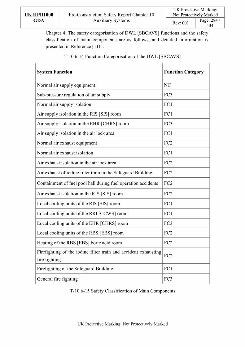
UK HPR1000
GDA
Pre-Construction Safety Report Chapter 10 Auxiliary Systems
UK Protective Marking: Not Protectively Marked
Rev: 001 Page: 284 /
504
UK Protective Marking: Not Protectively Marked
Chapter 4. The safety categorisation of DWL [SBCAVS] functions and the safety classification of main components are as follows, and detailed information is presented in Reference [111]:
T-10.6-14 Function Categorisation of the DWL [SBCAVS]
System Function Function Category
Normal air supply equipment NC
Sub-pressure regulation of air supply FC3
Normal air supply isolation FC1
Air supply isolation in the RIS [SIS] room FC1
Air supply isolation in the EHR [CHRS] room FC3
Air supply isolation in the air lock area FC1
Normal air exhaust equipment FC2
Normal air exhaust isolation FC1
Air exhaust isolation in the air lock area FC2
Air exhaust of iodine filter train in the Safeguard Building FC2
Containment of fuel pool hall during fuel operation accidents FC2
Air exhaust isolation in the RIS [SIS] room FC2
Local cooling units of the RIS [SIS] room FC1
Local cooling units of the RRI [CCWS] room FC1
Local cooling units of the EHR [CHRS] room FC3
Local cooling units of the RBS [EBS] room FC2
Heating of the RBS [EBS] boric acid room FC2
Firefighting of the iodine filter train and accident exhausting
fire fighting FC2
Firefighting of the Safeguard Building FC1
General fire fighting FC3
T-10.6-15 Safety Classification of Main Components
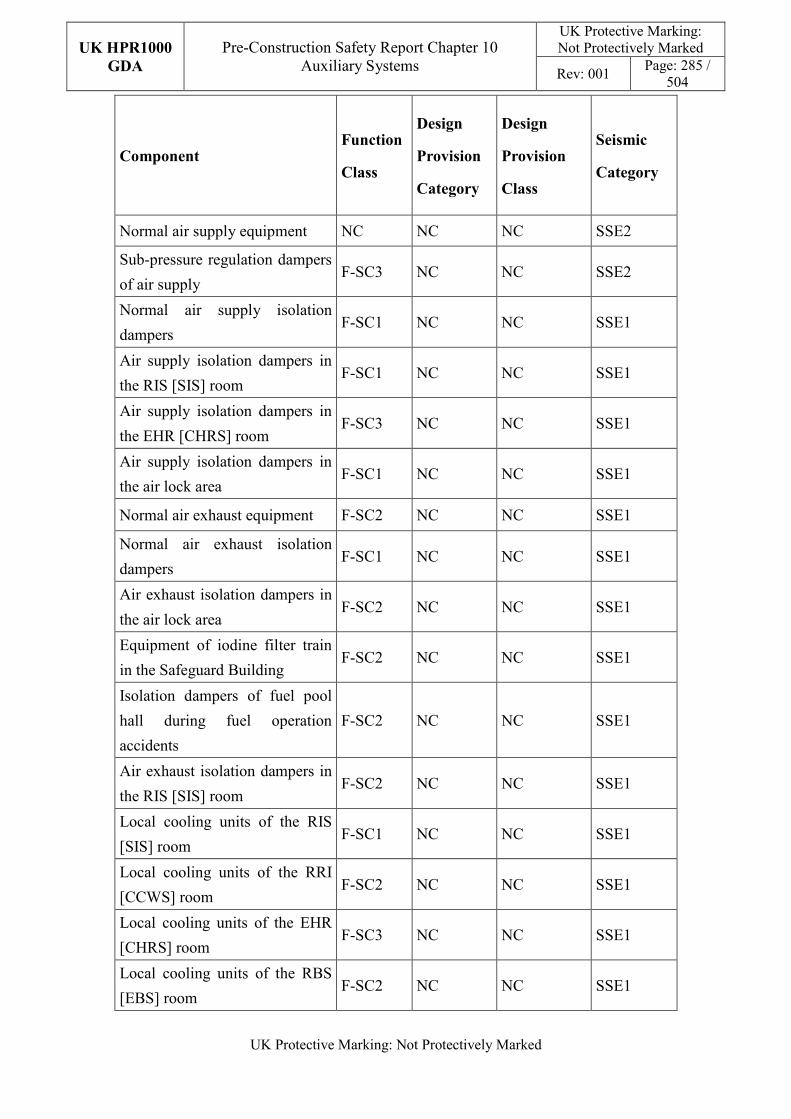
UK HPR1000
GDA
Pre-Construction Safety Report Chapter 10 Auxiliary Systems
UK Protective Marking: Not Protectively Marked
Rev: 001 Page: 285 /
504
UK Protective Marking: Not Protectively Marked
Component Function
Class
Design
Provision
Category
Design
Provision
Class
Seismic
Category
Normal air supply equipment NC NC NC SSE2
Sub-pressure regulation dampers
of air supply F-SC3 NC NC SSE2
Normal air supply isolation
dampers F-SC1 NC NC SSE1
Air supply isolation dampers in
the RIS [SIS] room F-SC1 NC NC SSE1
Air supply isolation dampers in
the EHR [CHRS] room F-SC3 NC NC SSE1
Air supply isolation dampers in
the air lock area F-SC1 NC NC SSE1
Normal air exhaust equipment F-SC2 NC NC SSE1
Normal air exhaust isolation
dampers F-SC1 NC NC SSE1
Air exhaust isolation dampers in
the air lock area F-SC2 NC NC SSE1
Equipment of iodine filter train
in the Safeguard Building F-SC2 NC NC SSE1
Isolation dampers of fuel pool
hall during fuel operation
accidents
F-SC2 NC NC SSE1
Air exhaust isolation dampers in
the RIS [SIS] room F-SC2 NC NC SSE1
Local cooling units of the RIS
[SIS] room F-SC1 NC NC SSE1
Local cooling units of the RRI
[CCWS] room F-SC2 NC NC SSE1
Local cooling units of the EHR
[CHRS] room F-SC3 NC NC SSE1
Local cooling units of the RBS
[EBS] room F-SC2 NC NC SSE1
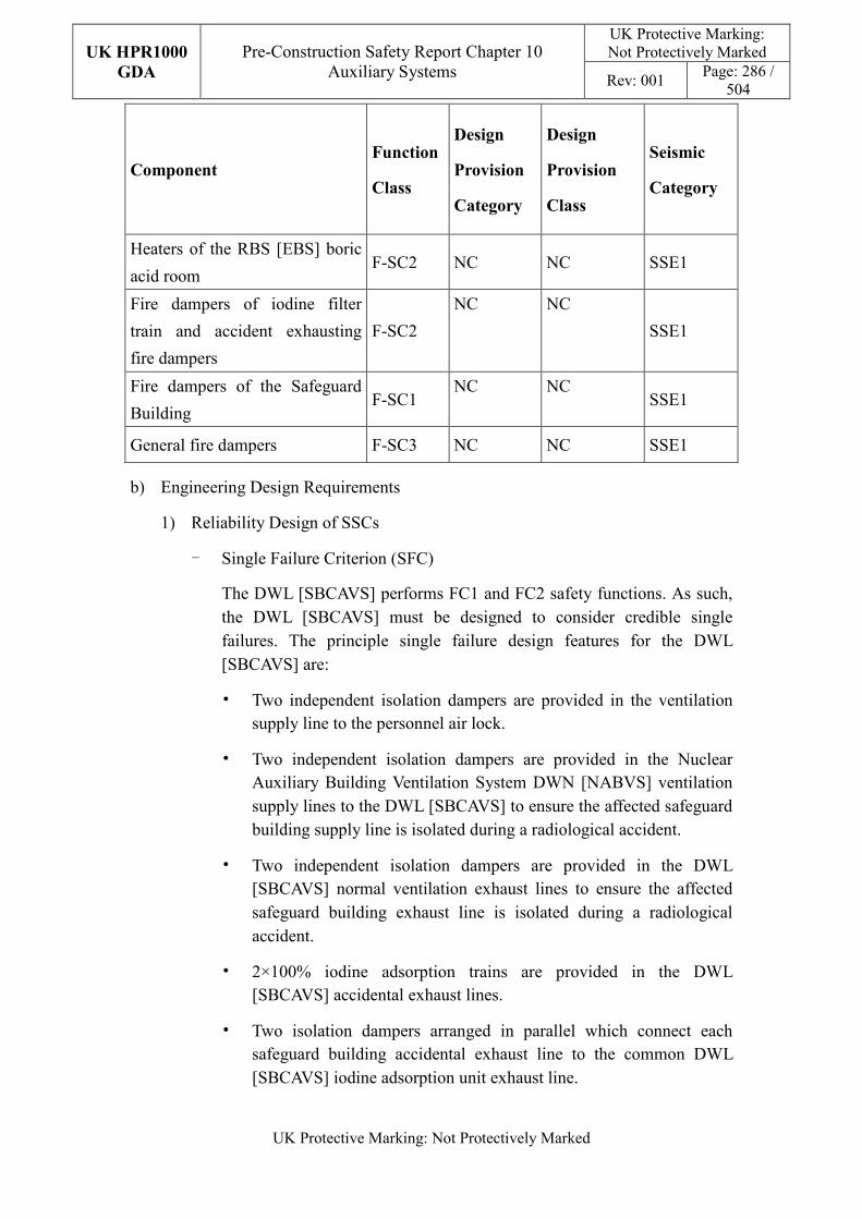
UK HPR1000
GDA
Pre-Construction Safety Report Chapter 10 Auxiliary Systems
UK Protective Marking: Not Protectively Marked
Rev: 001 Page: 286 /
504
UK Protective Marking: Not Protectively Marked
Component Function
Class
Design
Provision
Category
Design
Provision
Class
Seismic
Category
Heaters of the RBS [EBS] boric
acid room F-SC2 NC NC SSE1
Fire dampers of iodine filter
train and accident exhausting
fire dampers
F-SC2
NC NC
SSE1
Fire dampers of the Safeguard
Building F-SC1
NC NC SSE1
General fire dampers F-SC3 NC NC SSE1
b) Engineering Design Requirements
1) Reliability Design of SSCs
- Single Failure Criterion (SFC)
The DWL [SBCAVS] performs FC1 and FC2 safety functions. As such, the DWL [SBCAVS] must be designed to consider credible single failures. The principle single failure design features for the DWL [SBCAVS] are:
• Two independent isolation dampers are provided in the ventilation supply line to the personnel air lock.
• Two independent isolation dampers are provided in the Nuclear Auxiliary Building Ventilation System DWN [NABVS] ventilation supply lines to the DWL [SBCAVS] to ensure the affected safeguard building supply line is isolated during a radiological accident.
• Two independent isolation dampers are provided in the DWL [SBCAVS] normal ventilation exhaust lines to ensure the affected safeguard building exhaust line is isolated during a radiological accident.
• 2×100% iodine adsorption trains are provided in the DWL [SBCAVS] accidental exhaust lines.
• Two isolation dampers arranged in parallel which connect each safeguard building accidental exhaust line to the common DWL [SBCAVS] iodine adsorption unit exhaust line.
UK HPR1000
GDA
Pre-Construction Safety Report Chapter 10 Auxiliary Systems
UK Protective Marking: Not Protectively Marked
Rev: 001 Page: 287 /
504
UK Protective Marking: Not Protectively Marked
• Two isolation dampers arranged in parallel which connect the fuel pool area exhaust to the iodine adsorption units.
• Two fire dampers arranged in parallel are set at the safety fire zone boundary.
- Independence
The normal ventilation of the DWL [SBCAVS] consists of three separated trains (one train in each division of the safeguard building). The accident ventilation of the DWL [SBCAVS] consists of two separated trains located in different rooms of the fuel building.
The three trains of the DWL [SBCAVS] and dampers are powered by different electrical safety trains respectively, to ensure redundancy of the power supply.
- Diversity
The weakness of HVAC diversity design will be identified in Justification of the diversification of HVAC systems report. And a preliminary design of the diverse HVAC systems will be provided. Detailed diversity modification of HVAC systems will be finished in step 4..
- Fail-safe
The fail-safe concept is considered in the system design process.
The isolation dampers of the normal and accident air supply and exhaust ventilation, RIS [SIS] room air supply and exhaust ventilation, EHR [CHRS] room air supply ventilation and personnel airlock air supply and exhaust ventilation have fail-safe position. The fail-safe position of isolation dampers of the DWL [SBCAVS] listed above is the closed position.
- Ageing and Degradation
The plant design life is 60 years. Some components to be replaced at the end of their individual design life.
2) Human Factors
The system design of the DWL [SBCAVS] does not require short term operator intervention, however there are operator actions during plant normal operation, the effect of which needs to be estimated. The main equipment of the iodine adsorption trains is located in separate rooms in the fuel building, where the layout facilitates their maintenance. The DWL [SBCAVS] is controlled and monitored in the main control room. It is designed to be
UK HPR1000
GDA
Pre-Construction Safety Report Chapter 10 Auxiliary Systems
UK Protective Marking: Not Protectively Marked
Rev: 001 Page: 288 /
504
UK Protective Marking: Not Protectively Marked
convenient for the operator to control.
3) Autonomy
- Autonomy in Respect of Operators
The design principles relevant to the autonomy in respect of operators are detailed in Sub-chapter 10.2.4. The design of the DWL [SBCAVS] fulfils these principles via control functional design; detailed information is presented in the SDM, Reference [110]. The design result is estimated in the safety analysis.
- Autonomy in Respect of the Heat Sink
The design principles relevant to the autonomy in respect of the heat sink are not applicable for DWL [SBCAVS] design.
- Autonomy in Respect of Power Supply Systems
The design principles relevant to the autonomy in respect of the power supply are not applicable for DWL [SBCAVS] design.
4) Other Design Requirements
- Prevention of Harmful Interactions of Systems Important to Safety
Not applicable.
- Considerations Related to the Electrical Power Grid
The functionality of items important to safety in the DWL [SBCAVS] is not compromised by disturbances in the electrical power grid. Detailed design information of the electrical power grid is presented in Reference [107].
c) Equipment Qualification
All the safety components of the DWL [SBCAVS] required performing safety functions are capable of operating under both normal and accident conditions. As a result, the components can withstand the most adverse environmental conditions expected.
All the seismically classified components of the DWL [SBCAVS] shall be capable of operating during and after the SSE. The components are seismically designed and qualified for the SSE loads.
Principles of equipment qualification classification of the system are presented in Reference [111]. Detailed information related to the system equipment qualification is presented in Reference [107].
d) Protection against Internal and External Hazards
UK HPR1000
GDA
Pre-Construction Safety Report Chapter 10 Auxiliary Systems
UK Protective Marking: Not Protectively Marked
Rev: 001 Page: 289 /
504
UK Protective Marking: Not Protectively Marked
The HVAC systems comply with the requirements of external and internal hazards stated in Sub-chapter 10.2.4, for ventilation system, the corresponding protection measures of earthquake and internal fire are described as below.
1) External hazards
- Earthquake
The seismic category for the components of the DWL [SBCAVS] performing Safety Category 1 (FC1) and Safety Category 2 (FC2) is Seismic Category 1 (SSE1).
2) Internal hazards
- Internal Fire
The fire rating of the duct is same as the fire barrier when it passes through the barrier, if not, fire dampers are equipped in the duct. The fire rating of the duct is achieved by fireproof wrap.
Specific protection measures of other hazards are presented in Reference [109].
e) Commissioning
Commissioning and tests shall be carried out to validate the system’s functionality. The methodology of system commissioning programme design is presented in Reference [31]. Further detailed site specific arrangements for the UK HPR1000 commissioning activities will be presented during the nuclear site licencing phase in conjunction with the site licensee.
f) Examination, Inspection, Maintenance and Testing
1) Examination and Inspection
There is no equipment of the DWL [SBCAVS] requiring in-service inspection.
The combined information of the DWL [SBCAVS] displayed in the Main Control Room (MCR) for the operator includes:
- Differential pressure between internal and external areas;
- Room temperature monitoring;
- Temperature downstream of the electric heaters;
- System exhaust volume measurement;
- Position of isolated dampers;
- Position of the volume control dampers;
UK HPR1000
GDA
Pre-Construction Safety Report Chapter 10 Auxiliary Systems
UK Protective Marking: Not Protectively Marked
Rev: 001 Page: 290 /
504
UK Protective Marking: Not Protectively Marked
- Position of fire dampers;
- Status of fans;
- Status of electric heaters.
2) Maintenances
During normal operating conditions, the DWL [SBCAVS] should provide suitable environmental conditions for the controlled area of the safeguard building. Maintenance of the components could be done during shutdown of the plant.
The maintenance of iodine adsorption trains is performed during plant shutdown when there is no fuel handling operations.
3) Periodic Tests
For the UK HPR1000, the periodic test design method is presented in the Reference [32].
FC1, FC2 and FC3 equipment should be tested if they are not in continuous operation. Some equipment performing safety function shall be subject to periodic testing, mainly including:
- Efficiency of HEPA filters;
- Efficiency of iodine adsorbers;
- Operation of the extraction fans and heaters;
- Operability of the motorised isolation dampers;
- Operability of local cooling units.
g) Decommissioning
Decommissioning considerations are taken into account of system design. The principles are given in SDM chapter 3, Reference [111].
h) Material Selection
Ducts of the DWL [SBCAVS] usually use galvanised steel plate.
In the areas which require equipment to be air tight, the air tight duct is used.
The duct is made of carbon steel or stainless steel with a painted surface.
In the fire resistant duct area, the duct fireproof package is required.
10.6.9.6 Simplified Diagrams
The simplified system functional diagram is presented in Figure F-10.6-7; the detailed
UK HPR1000
GDA
Pre-Construction Safety Report Chapter 10 Auxiliary Systems
UK Protective Marking: Not Protectively Marked
Rev: 001 Page: 291 /
504
UK Protective Marking: Not Protectively Marked
system functional diagrams are presented in Reference [112].
10.6.10 Electrical Division of Safeguard Building Ventilation System (DVL
[EDSBVS])
The DVL [EDSBVS] provides ventilation for uncontrolled areas of the safeguard building. Information of the system is presented in the SDM chapter 2, Reference [114].
10.6.10.1 Safety Functional Requirements
10.6.10.1.1 Control of Reactivity
The DVL [EDSBVS] does not contribute to this safety function.
10.6.10.1.2 Removal of Heat
The DVL [EDSBVS] does not contribute to this safety function.
10.6.10.1.3 Confinement
The DVL [EDSBVS] does not contribute to this safety function.
10.6.10.1.4 Extra Safety Functions
With respect to its contribution to the extra functions, the DVL [EDSBVS] system must satisfy the following requirements:
a) Supporting The Fundamental Safety Functions
The DVL [EDSBVS] provides the acceptable ambient conditions for safety classified equipment in uncontrolled areas of the safeguard building during plant normal conditions and plant accident conditions.
b) Prevent, Protect and Mitigate Hazards Impact
1) Fire
The DVL [EDSBVS] must prevent fire from affecting the operation of safety-related equipment and safety of staff in the Safeguard Buildings (BSX).
The DVL [EDSBVS] must maintain the acceptable environment of the Remote Shutdown Station (RSS) in the event of fire in the MCR.
2) External Explosion
The DVL [EDSBVS] must prevent external explosions from affecting the operation of safety-related equipment located in the BSX.
3) Internal Explosion
The DVL [EDSBVS] must ensure the concentration of hydrogen in the
UK HPR1000
GDA
Pre-Construction Safety Report Chapter 10 Auxiliary Systems
UK Protective Marking: Not Protectively Marked
Rev: 001 Page: 292 /
504
UK Protective Marking: Not Protectively Marked
battery rooms is below the explosive limit.
10.6.10.2 Design Requirements
The general design requirements of the HVAC systems which need to be considered are shown in Sub-chapter 10.2.4, among which the following requirements are not applicable for the DVL [EDSBVS]:
a) Autonomy in Respect of the Heat Sink
Not applicable, because the DVL [EDSBVS] doesn’t provide a heat sink to the power plant.
b) Autonomy in Respect of Power Supply Systems
Not applicable, because the DVL [EDSBVS] doesn’t provide a power supply to the power plant.
c) Prevention of Harmful Interactions of Systems Important to Safety
Not applicable, because the DVL [EDSBVS] doesn’t have harmful interactions of systems important to safety.
The substantiation analysis of the DVL [EDSBVS] to other design requirements is shown in the Sub-chapter 10.6.10.5.2.
10.6.10.3 Design Bases
10.6.10.3.1 General Assumptions
a) For each safeguard building division, there is a 100% normal operation train and a 100% maintenance train.
b) Exhaust air from I&C and switchgear cabinet rooms is recirculated, but exhaust air from the mechanical areas and battery rooms, chiller rooms is directly discharged outside.
c) There is a 100% local cooling unit serving each RRI [CCWS] pump, and it also serves the ASG [EFS] pump.
10.6.10.3.2 Design Assumptions
a) Control of Reactivity
Not applicable. The DVL [EDSBVS] does not directly contribute to the safety function of control of reactivity.
b) Removal of Heat
Not applicable. The DVL [EDSBVS] does not directly contribute to the safety function of removal of heat.
UK HPR1000
GDA
Pre-Construction Safety Report Chapter 10 Auxiliary Systems
UK Protective Marking: Not Protectively Marked
Rev: 001 Page: 293 /
504
UK Protective Marking: Not Protectively Marked
c) Confinement
Not applicable. The DVL [EDSBVS] does not directly contribute to the safety function of confinement.
d) Extra Safety Functions
1) Supporting The Fundamental Safety Functions
- The external conditions to be taken into account for the DVL [EDSBVS] are defined in Table T-10.6-41.
- The internal conditions to be taken into account for the DVL [EDSBVS] are defined in Tables T-10.6-43 and T-10.6-44.
- The temperature of the supply air is 18°C.
- The capacity of the ventilation system considers the maximum heat dissipation of the equipment and pipes under plant normal operation and plant accident conditions.
- The capacity of the local cooling units is considered for plant normal operation and plant accident conditions, when the normal ventilation is lost and with regards to the maximum heat dissipation of the equipment and pipes.
- Requirements for the minimum air renewal rate are detailed in Table T-10.6-45.
2) Prevent, Protect and Mitigate Hazards Impact
- Fire
The fire dampers must be closed automatically when air temperature is
higher than 70℃.
- External Explosion
The parameters of external explosions are given in Chapter 18 (External Hazards).
- Internal Explosion
The DVL [EDSBVS] must ensure the minimum air renewal rate and continual ventilation in the battery rooms.
10.6.10.4 System Description and Operation
10.6.10.4.1 System Description
a) General System Description
UK HPR1000
GDA
Pre-Construction Safety Report Chapter 10 Auxiliary Systems
UK Protective Marking: Not Protectively Marked
Rev: 001 Page: 294 /
504
UK Protective Marking: Not Protectively Marked
The DVL [EDSBVS] consists of three independence ventilation divisions. Each ventilation division contains one normal operation train and one maintenance train. Both of them have the ability to manage air through filtering, heating and cooling (normal operation train is cooled by the DEL [SCWS], maintenance train is cooled by the DER [OCWS]) individually.
The local cooling units are installed in the mechanical area of each safeguard building division to provide cooling for the RRI [CCWS] and ASG [EFS] rooms.
The RSS is physically located in safeguard building division C, and is ventilated by DVL [EDSBVS] division C normally. DVL [EDSBVS] division A is used in the event of a fire in safeguard building division C or unavailability of DVL [EDSBVS] Division C.
Each air conditioning division of the DVL [EDSBVS] includes the following equipment:
1) A single fresh air intake equipped with explosion pressure wave dampers;
2) Supply air treatment train -100% capacity (the pre-heater, filter, electric heater, cooling coil, humidifier and fan are included);
3) Exhaust air treatment train -100% capacity (one recirculation fan);
4) Special Exhaust air treatment train -100% capacity (one exhaust fan);
5) An exhaust outlet equipped with explosion pressure wave dampers;
6) Dampers, duct network and a set of accessory.
Detailed information of the systems is presented in the SDM, Reference [113].
b) Description of Main Equipment
1) Fans
Fans are centrifugal and direct-coupled drive type.
2) Pre-heaters
The pre-heaters are designed to maintain the air temperature by heating the air to avoid the risk of condensation when mixing fresh air and return air.
3) Cooling Coils
The coils are designed to cool the air and they are made of copper tubes with several passes depending on the thermal characteristics, with copper or aluminium fins. The frames are made of galvanised steel or stainless steel.
4) Electrical Heaters
The electric heaters are designed to maintain the air temperature by heating
UK HPR1000
GDA
Pre-Construction Safety Report Chapter 10 Auxiliary Systems
UK Protective Marking: Not Protectively Marked
Rev: 001 Page: 295 /
504
UK Protective Marking: Not Protectively Marked
the air and are comprised of reinforced tubular elements placed in a sheet metal box.
5) Pre-filters
The pre-filters are designed to filter dust in the air and their efficiency is more than 85% (weighting method).
6) Fine Filters
The fine filters are designed to filter dust in the air and their efficiency is more than 90% (counting method).
7) Local Cooling Units
The local cooling units are designed to provide cooling to the air. A local cooling unit consists of a fan and a cooling coil supplied with chilled water.
8) Humidifiers
The humidifiers are designed to ensure the necessary relative humidity conditions. They are independent units that inject steam at the required rate directly into the duct.
9) Isolation Dampers
The isolation dampers are designed to ensure the isolation of air entry and exhaust in the BSX.
Detailed information of the equipment design is presented in the SDM chapter 4, Reference [113].
c) Description of Main Layout
The main equipment of each DVL [EDSBVS] division is located in the corresponding safeguard building division.
Detailed design information about the system layout is presented in the SDM, Reference [115].
d) Description of System Interfaces
The DVL [EDSBVS] system is connected to the following mechanical systems (not including power supplies and I&C systems):
1) DEL [SCWS]
This system provides chilled water to the safety classified DVL [EDSBVS] cooling coils of the normal operation trains.
2) DER [OCWS]
UK HPR1000
GDA
Pre-Construction Safety Report Chapter 10 Auxiliary Systems
UK Protective Marking: Not Protectively Marked
Rev: 001 Page: 296 /
504
UK Protective Marking: Not Protectively Marked
This system provides chilled water to the non-safety classified DVL [EDSBVS] cooling coils of the maintenance train.
3) JDT [FAS]
This system provides fire signals to control the fire dampers of the DVL [EDSBVS].
4) Station Sewer System (SEO [SSS])
This system collects drainage water from the DVL [EDSBVS] main cooling coils located in the normal operation train and maintenance train.
5) RPE [VDS]
This system collects drainage water from the DVL [EDSBVS] local cooling units.
Detailed information of the interface systems is presented in the SDM, Reference [113].
e) Description of Instrumentation and Control
Instruments, controlling and monitoring the DVL [EDSBVS] and displaying of the actuator are provided in the Main Control Room.
Detailed information of the system I&C design is presented in the SDM, Reference [116].
10.6.10.4.2 System Operation
a) Plant Normal Conditions
The DVL [EDSBVS] operates in recycling mode with fresh makeup air, and all of the three normal operation divisions are in operation during plant normal operation.
If the normal operational train is unavailable, the maintenance train can be activated.
b) Plant Accident Conditions
Normal operation trains of the DVL [EDSBVS] remain in operation in the event of a LOOP.
Normal operation trains of the DVL [EDSBVS] train A and B remain in operation in the event of a SBO.
Normal operation trains of the DVL [EDSBVS] train A and B remain in operation in the event of the LUHS.
UK HPR1000
GDA
Pre-Construction Safety Report Chapter 10 Auxiliary Systems
UK Protective Marking: Not Protectively Marked
Rev: 001 Page: 297 /
504
UK Protective Marking: Not Protectively Marked
10.6.10.5 Preliminary Design Substantiation
In this sub-chapter, the system design is demonstrated to satisfy the safety functional requirements presented in Sub-chapter 10.6.10.1 and the general design requirements stated in Sub-chapter 10.2.4. Review of the consistency of the system design against the newly developed principles is currently being undertaken.
10.6.10.5.1 Compliance with Safety Functional Requirements
a) Control of Reactivity
Not applicable.
b) Removal of Heat
Not applicable.
c) Confinement
Not applicable.
d) Extra Safety Functions
1) Supporting The Fundamental Safety Functions
The DVL [EDSBVS] components are sized to meet the environmental requirements of equipment in the BSX under all summer and winter conditions as defined in Table T-10.6-41.
2) Prevent, Protect and Mitigate Hazards Impact
- Fire
Fire dampers can be closed to ensure the containment of fire and to maintain the fire compartment integrity by the JDT [FAS] signal or fuse.
The ventilation of the RSS can be switched to DVL [EDSBVS] train C.
- External Explosion
Explosion Pressure Wave (EPW) dampers are installed at the intake of the DVL [EDSBVS] to prevent external explosions from affecting the system functions.
- Internal Explosion
The DVL [EDSBVS] fans are sized to meet the minimum air renewal rate requirements and a backup fan can be started if the main fan is lost.
Detailed design information is presented in Reference [117].
UK HPR1000
GDA
Pre-Construction Safety Report Chapter 10 Auxiliary Systems
UK Protective Marking: Not Protectively Marked
Rev: 001 Page: 298 /
504
UK Protective Marking: Not Protectively Marked
10.6.10.5.2 Compliance with Design Requirements
a) Safety Classification
The DVL [EDSBVS] design is compliant with the principles described in Chapter 4. The safety categorisation of DVL [EDSBVS] functions and the safety classification of man components are as follows, and detailed information is presented in Reference [117]:
T-10.6-16 Function Categorisation of the DVL [EDSBVS]
System Function Function Category
Normal operation train of filtering, air conditioning and
ventilation FC1
Maintenance train of filtering, air conditioning and ventilation
NC
Heating of communication device room NC
Ventilation of the RSS FC3
Local cooling units FC1
T-10.6-17 Classification of Main Components
Component Function
Class
Design
Provision
Category
Design
Provision
Class
Seismic
Category
Normal operation
train
Fans F-SC2 NC NC SSE1
Filters F-SC2 NC NC SSE1
Pre-heater, Electric heaters
F-SC2 NC
NC SSE1
Cooling coils F-SC2 NC NC SSE1
Silencers F-SC2 NC NC SSE1
Dampers F-SC2 NC NC SSE1
Maintenance train
Fans NC NC NC SSE2
Filters NC NC NC SSE2
Pre-heater, Electric heaters
NC NC
NC SSE2
Cooling coils NC NC NC SSE2
Silencers NC NC NC SSE2
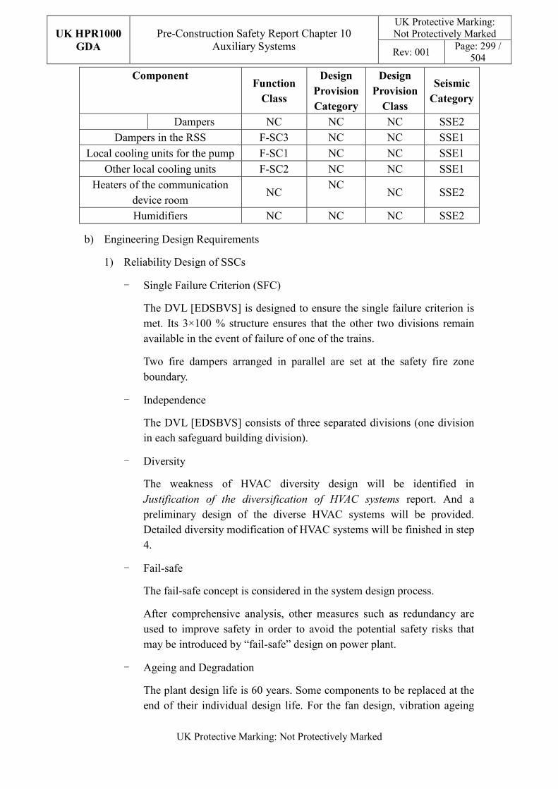
UK HPR1000
GDA
Pre-Construction Safety Report Chapter 10 Auxiliary Systems
UK Protective Marking: Not Protectively Marked
Rev: 001 Page: 299 /
504
UK Protective Marking: Not Protectively Marked
Component Function
Class
Design
Provision
Category
Design
Provision
Class
Seismic
Category
Dampers NC NC NC SSE2
Dampers in the RSS F-SC3 NC NC SSE1
Local cooling units for the pump F-SC1 NC NC SSE1
Other local cooling units F-SC2 NC NC SSE1
Heaters of the communication device room
NC NC
NC SSE2
Humidifiers NC NC NC SSE2
b) Engineering Design Requirements
1) Reliability Design of SSCs
- Single Failure Criterion (SFC)
The DVL [EDSBVS] is designed to ensure the single failure criterion is met. Its 3×100 % structure ensures that the other two divisions remain available in the event of failure of one of the trains.
Two fire dampers arranged in parallel are set at the safety fire zone boundary.
- Independence
The DVL [EDSBVS] consists of three separated divisions (one division in each safeguard building division).
- Diversity
The weakness of HVAC diversity design will be identified in Justification of the diversification of HVAC systems report. And a preliminary design of the diverse HVAC systems will be provided. Detailed diversity modification of HVAC systems will be finished in step 4.
- Fail-safe
The fail-safe concept is considered in the system design process.
After comprehensive analysis, other measures such as redundancy are used to improve safety in order to avoid the potential safety risks that may be introduced by “fail-safe” design on power plant.
- Ageing and Degradation
The plant design life is 60 years. Some components to be replaced at the end of their individual design life. For the fan design, vibration ageing
UK HPR1000
GDA
Pre-Construction Safety Report Chapter 10 Auxiliary Systems
UK Protective Marking: Not Protectively Marked
Rev: 001 Page: 300 /
504
UK Protective Marking: Not Protectively Marked
and thermal ageing are taken into consideration. The differential pressure of the fan is monitored and recorded in real time, which is convenient for the operator to judge the performance of the fan.
2) Human Factors
The system design of the DVL [EDSBVS] does not require short term operator intervention, however there are operator actions during plant normal operation, the effect of which needs to be estimated. The fan, filter, coil and heater of each DVL [EDSBVS] train are located in adjacent equipment rooms, where the layout facilitates their maintenances. The DVL [EDSBVS] is controlled and monitored in the main control room. It is designed to be easy to control for the operator.
3) Autonomy
- Autonomy in Respect of Operators
The design principles relevant to the autonomy in respect of operators are detailed in Sub-chapter 10.2.4. The design of the DVL [EDSBVS] fulfils these principles via control functional design; detailed information is presented in the SDM, Reference [116]. The design result is estimated in the safety analysis.
- Autonomy in Respect of the Heat Sink
The design principles relevant to the autonomy in respect of the heat sink are not applicable for DVL [EDSBVS] design.
- Autonomy in Respect of Power Supply Systems
The design principles relevant to the autonomy in respect of the power supply are not applicable for DVL [EDSBVS] design.
4) Other Design Requirements
- Prevention of Harmful Interactions of Systems Important to Safety
Not applicable.
- Considerations Related to the Electrical Power Grid
The functionality of items important to safety in the DVL [EDSBVS] is not compromised by disturbances in the electrical power grid. Detailed design information of the electrical power grid is presented in Reference [113].
c) Equipment Qualification
All the safety classified components of the DVL [EDSBVS] required to perform
UK HPR1000
GDA
Pre-Construction Safety Report Chapter 10 Auxiliary Systems
UK Protective Marking: Not Protectively Marked
Rev: 001 Page: 301 /
504
UK Protective Marking: Not Protectively Marked
safety functions are capable of operating under both normal and accident conditions. As a result, the components can withstand the most adverse environmental conditions expected.
All the seismically classified components of the DVL [EDSBVS] shall be capable of operating during and after the SSE. The components are seismically designed and qualified for the SSE loads.
Principles of equipment qualification classification of the system are presented in Reference [117]. Detailed information related to the system equipment qualification is presented in Reference [113].
d) Protection against Internal and External Hazards
The HVAC systems comply with the requirements of external and internal hazards stated in Sub-chapter 10.2.4, for ventilation system, the corresponding protection measures of earthquake and internal fire are described as below.
1) External hazards
- Earthquake
The seismic category for the components of the DVL [EDSBVS] performing Safety Category 1 (FC1) and Safety Category 2 (FC2) is Seismic Category 1 (SSE1), others are Seismic Category 2 (SSE2).
2) Internal hazards
- Internal Fire
The fire rating of the duct is same as the fire barrier when it passes through the barrier, if not, fire dampers are equipped in the duct. The fire rating of the duct is achieved by fireproof wrap.
Specific protection measures of other hazards are presented in Reference [115].
e) Commissioning
Commissioning and tests shall be carried out to validate the system’s functionality. The methodology of system commissioning programme design is presented in Reference [31]. Further detailed site specific arrangements for the UK HPR1000 commissioning activities will be presented during the nuclear site licencing phase in conjunction with the site licensee.
f) Examination, Inspection, Maintenance and Testing
1) Examination and Inspection
There is no equipment of the DVL [EDSBVS] requiring in-service inspection.
UK HPR1000
GDA
Pre-Construction Safety Report Chapter 10 Auxiliary Systems
UK Protective Marking: Not Protectively Marked
Rev: 001 Page: 302 /
504
UK Protective Marking: Not Protectively Marked
The combined information of the DVL [EDSBVS] displayed in the Main Control Room (MCR) for the operator includes:
- Temperature of supplied air;
- Temperature in the mechanical and electrical rooms.
2) Maintenances
Maintenance can be done when users served by the corresponding train are in maintenance during the shutdown of plant.
3) Periodic Tests
For the UK HPR1000, the periodic test design method is presented in the Reference [32].
FC1, FC2 and FC3 equipment should be tested if they are not in continuous operation. Some equipment performing safety functions shall be subject to periodic test, including:
- RSS isolation dampers opening operability;
- Operability of local cooling units;
- Availability test of the main heaters.
g) Decommissioning
Decommissioning considerations are taken into account of system design. The principles are given in SDM chapter 3, Reference [117].
h) Material Selection
The equipment in contact with outside air is made of stainless steel.
The duct material is galvanised steel.
The fireproof duct is made of a metal duct and a fireproof wrap.
10.6.10.6 Simplified Diagrams
The simplified system diagram is presented in Figure F-10.6-8; the detailed system functional diagrams are presented in Reference [118].
10.6.11 Main Control Room Air Conditioning System (DCL [MCRACS])
The DCL [MCRACS] maintains the environment (including temperature, humidity, concentration of radioactive materials) of the MCR and associated rooms in normal operating condition and accident condition. Information of the system is presented in the SDM chapter 2, Reference [120].
UK HPR1000
GDA
Pre-Construction Safety Report Chapter 10 Auxiliary Systems
UK Protective Marking: Not Protectively Marked
Rev: 001 Page: 303 /
504
UK Protective Marking: Not Protectively Marked
10.6.11.1 Safety Functional Requirements
10.6.11.1.1 Control of Reactivity
The DCL [MCRACS] does not contribute to this safety function.
10.6.11.1.2 Removal of Heat
The DCL [MCRACS] does not contribute to this safety function.
10.6.11.1.3 Confinement
The DCL [MCRACS] does not contribute to this safety function.
10.6.11.1.4 Extra Safety Functions
With respect to its contribution to the extra functions, the DCL [MCRACS] must satisfy the following requirements:
a) Supporting the Fundamental Safety Functions
During plant normal operation and accidents, the DCL [MCRACS] maintains acceptable temperatures and humidity inside the MCR and associated rooms for proper operation of equipment and the wellbeing of personnel. The DCL [MCRACS] also provides habitability protection for the MCR, technical support centre and associated rooms during events which lead to radiological contamination of the environment.
b) Prevent, Protect and Mitigate Hazards Impact
1) Fire
The DCL [MCRACS] must prevent fire from affecting the operation of safety-related equipment by maintaining fire compartment integrity.
2) External explosion
The DCL [MCRACS] must prevent external explosions from affecting the classified equipment.
10.6.11.2 Design Requirements
The general design requirements of the HVAC systems which need to be considered are shown in Sub-chapter 10.2.4, among which the following requirements are not applicable for the DCL [MCRACS]:
a) Autonomy in Respect of the Heat Sink
Not applicable, because the DCL [MCRACS] doesn’t provide a heat sink to the power plant.
b) Autonomy in Respect of Power Supply Systems
UK HPR1000
GDA
Pre-Construction Safety Report Chapter 10 Auxiliary Systems
UK Protective Marking: Not Protectively Marked
Rev: 001 Page: 304 /
504
UK Protective Marking: Not Protectively Marked
Not applicable, because the DCL [MCRACS] doesn’t provide a power supply to the power plant.
c) Prevention of Harmful Interactions of Systems Important to Safety
Not applicable, because the DCL [MCRACS] doesn’t have harmful interactions of systems important to safety.
The substantiation analysis of the DCL [MCRACS] to other design requirements is shown in the Sub-chapter 10.6.11.5.2.
10.6.11.3 Design Bases
10.6.11.3.1 General Assumptions
The DCL [MCRACS] system has 3×100% air conditioning trains with the mix of fresh and return air and 2×100% iodine filtration trains with return filtering. The air duct heater is designed in some rooms, so that the minimum temperature of each room can be maintained.
10.6.11.3.2 Design Assumptions
a) Control of Reactivity
Not applicable. The DCL [MCRACS] does not contribute to the safety function of control of reactivity.
b) Removal of Heat
Not applicable. The DCL [MCRACS] does not contribute to the safety function of removal of heat.
c) Confinement
Not applicable. The DCL [MCRACS] does not contribute to the safety function of confinement.
d) Extra Safety Functions
1) Supporting the Fundamental Safety Functions
- The internal conditions to be taken into account for the DCL [MCRACS] are defined in Tables T-10.6-43 and T-10.6-44.
- The external conditions to be taken into account for the DCL [MCRACS] are defined in Table T-10.6-41.
- The temperature of the supply air is 17°C.
- The capacity of the DCL [MCRACS] considers the fresh air load and the maximum heat load of the equipment and lighting.
UK HPR1000
GDA
Pre-Construction Safety Report Chapter 10 Auxiliary Systems
UK Protective Marking: Not Protectively Marked
Rev: 001 Page: 305 /
504
UK Protective Marking: Not Protectively Marked
- During radioactive contamination accidents at the plant, the DCL [MCRACS] maintains a positive pressure of 30Pa in the MCR habitable area.
2) Prevent, Protect and Mitigate Hazards Impact
- Fire
The fire dampers must be closed automatically when air temperature is
higher than 70℃.
- External explosion
The parameters of external explosion which must be taken into consideration are given in Chapter 18 (External Hazards).
e) Other Assumptions
Not applicable. There’s no other quantitative design assumption for the DCL [MCRACS].
10.6.11.4 System Description and Operation
10.6.11.4.1 System Description
a) General System Description
The DCL [MCRACS] consists of three separate air conditioning trains and two separate iodine filtration trains. The kitchen and bathroom have separate exhaust fans. The main components of the system are as follows:
1) Two fresh air inlets equipped with EPW dampers;
2) 3×100% supply air conditioning trains, each train includes a filter, cooling coil, fan and humidifier;
3) 1×100% exhaust fan;
4) 2×100% iodine filtration two trains, each train includes a pre-filler, pre-HEPA filter, iodine adsorber, post- HEPA filter and fan;
5) Dampers, a duct network and a set of accessories.
Detailed information of the systems is presented in the SDM, Reference [119].
b) Description of Main Equipment
1) Fans
The fans are centrifugal or axial, depending on the system flow rate and head loss. The safety fans are a direct-coupled drive type.
2) Electrical Heaters
UK HPR1000
GDA
Pre-Construction Safety Report Chapter 10 Auxiliary Systems
UK Protective Marking: Not Protectively Marked
Rev: 001 Page: 306 /
504
UK Protective Marking: Not Protectively Marked
The electric heaters heat outside air during periods of cold weather to ensure the DCL [MCRACS] supply air temperature requirements are met. They are also designed to maintain the relative humidity of the iodine adsorber inlet (the supply air temperature) by heating the air and are comprised of reinforced tubular elements placed in a sheet metal box.
3) HEPA Filters
The HEPA filters are designed to filter dust or aerosols in the air. Each HEPA filter cell is individually factory tested to verify an efficiency of at least 99.99%, corresponding to a 10000 filtering factor (sodium flame method).
4) Iodine Adsorbers
The iodine adsorbers are designed to remove radioactive iodine suspended in the air. Each adsorber is assembly with a welded construction and a 102mm deep Type III rechargeable adsorber cell. When new, these filters have a filtering factor of at least 1000 (methyl iodide).
5) Air handling units
The air handling units are designed to manage the air intake, they consist of pre-filters, fine filters, cooling coils, fan and humidifier.
- Pre-filters
The filters are designed to filter dust in the air and their efficiency is more than 85% (weighting method).
- Fine Filters
The filters are designed to filter dust in the air and their efficiency is more than 90% (counting method).
- Cooling Coils
The cooling coils are designed to cool the air and they are made of copper tubes with several passes depending on the thermal characteristics, with copper or aluminium fins. The frames are made of galvanised steel or stainless steel.
- Humidifier
The humidifier is designed to ensure the necessary relative humidity conditions are met. They are independent units that inject steam at the required rate directly into the air handling units.
Detailed information of the equipment design is presented in the SDM chapter 4, Reference [119].
UK HPR1000
GDA
Pre-Construction Safety Report Chapter 10 Auxiliary Systems
UK Protective Marking: Not Protectively Marked
Rev: 001 Page: 307 /
504
UK Protective Marking: Not Protectively Marked
c) Description of Main Layout
The equipment and duct of the DCL [MCRACS] are located in safeguard building train C.
Detailed design information about the system layout is presented in the SDM, Reference [121].
d) Description of System Interface
The DCL [MCRACS] system is connected to the following mechanical systems (not including power supplies and I&C systems):
1) DEL [SCWS]
This system provides chilled water to the cooling coils of the DCL [MCRACS].
2) Radiation Monitoring System (KRT [PRMS])
This system detects site contamination and develops a switch signal for the DCL [MCRACS].
3) Fire Alarm System (JDT [FAS])
This system provides the fire signal to the fire dampers of the DCL [MCRACS].
4) Nuclear Island Potable Water System (SEP [PWS (NI)])
This system provides water to the DCL [MCRACS] humidifiers.
5) Fire-fighting Water System for Nuclear Island (JPI [NIFPS])
This system provides water to the charcoal filter in case of a fire.
Detailed information of the interface systems is presented in the SDM, Reference [119].
e) Description of Instrumentation and Control
Parameters, controlling and monitoring of the DCL [MCRACS] and displaying of the actuator are provided in the Main Control Room.
Detailed information of the system I&C design is presented in the SDM, Reference [122].
10.6.11.4.2 System Operation
a) Plant Normal Conditions
One of the three air conditioning trains operates continuously during plant normal conditions and the DCL [MCRACS] operates in recycling mode with fresh air
UK HPR1000
GDA
Pre-Construction Safety Report Chapter 10 Auxiliary Systems
UK Protective Marking: Not Protectively Marked
Rev: 001 Page: 308 /
504
UK Protective Marking: Not Protectively Marked
makeup.
b) Plant Accident Conditions
Under plant accident conditions, one of the three air conditioning trains operating continuously can meet the cooling requirements.
In case of LOOP, each train is powered by a corresponding emergency diesel generator. As such, one of the three trains remains operable during any LOOP event which is sufficient to maintain continuous operation of the components served by the DCL [MCRACS].
In case of a SBO, the equipment of trains A and train B are powered by the SBO diesel generators. Train C does not operate.
In case of Loss of Ultimate Heat Sink (LUHS), trains A or train B can remain operational. Train C does not operate.
In case of a radiological site contamination event, train A with the iodine absorption line or the train B with the iodine absorption line remains operational. And the exhaust fan can be closed automatically.
Detailed information of the system operation is presented in the SDM, Reference [122].
10.6.11.5 Preliminary Design Substantiation
In this sub-chapter, the system design is demonstrated to satisfy the safety functional requirements presented in Sub-chapter 10.6.11.1 and the general Design requirements stated in Sub-chapter 10.2.4. Review of the consistency of the system design against the newly developed principles is currently being undertaken.
10.6.11.5.1 Compliance with Safety Functional Requirements
a) Control of Reactivity
Not applicable.
b) Removal of Heat
Not applicable.
c) Confinement
Not applicable.
d) Extra Safety Functions
1) Supporting the Fundamental Safety Functions
Components of the DCL [MCRACS] are sized to meet the cooling requirements in the MCR area under normal or accident conditions.
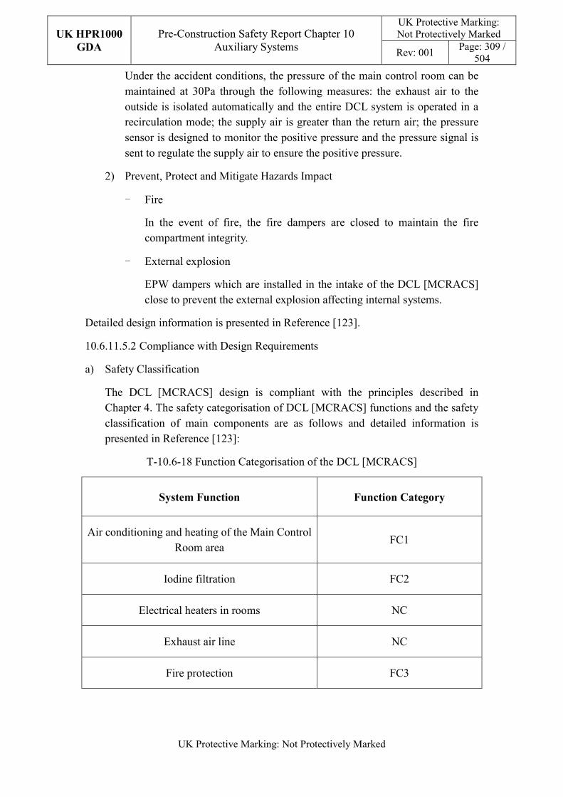
UK HPR1000
GDA
Pre-Construction Safety Report Chapter 10 Auxiliary Systems
UK Protective Marking: Not Protectively Marked
Rev: 001 Page: 309 /
504
UK Protective Marking: Not Protectively Marked
Under the accident conditions, the pressure of the main control room can be maintained at 30Pa through the following measures: the exhaust air to the outside is isolated automatically and the entire DCL system is operated in a recirculation mode; the supply air is greater than the return air; the pressure sensor is designed to monitor the positive pressure and the pressure signal is sent to regulate the supply air to ensure the positive pressure.
2) Prevent, Protect and Mitigate Hazards Impact
- Fire
In the event of fire, the fire dampers are closed to maintain the fire compartment integrity.
- External explosion
EPW dampers which are installed in the intake of the DCL [MCRACS] close to prevent the external explosion affecting internal systems.
Detailed design information is presented in Reference [123].
10.6.11.5.2 Compliance with Design Requirements
a) Safety Classification
The DCL [MCRACS] design is compliant with the principles described in Chapter 4. The safety categorisation of DCL [MCRACS] functions and the safety classification of main components are as follows and detailed information is presented in Reference [123]:
T-10.6-18 Function Categorisation of the DCL [MCRACS]
System Function Function Category
Air conditioning and heating of the Main Control Room area
FC1
Iodine filtration FC2
Electrical heaters in rooms NC
Exhaust air line NC
Fire protection FC3
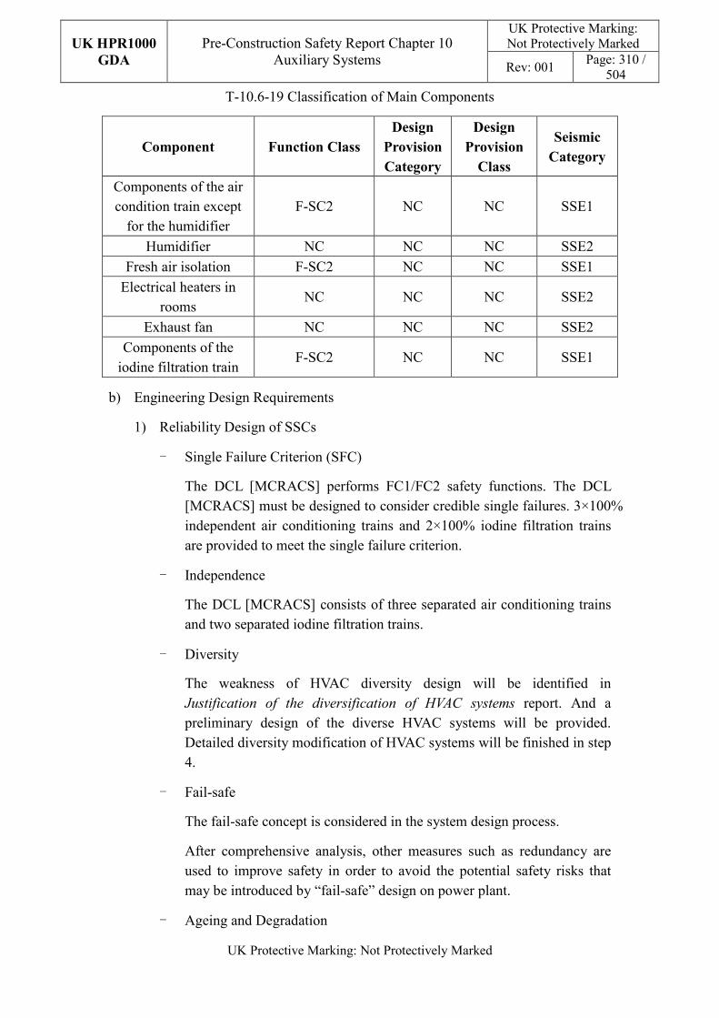
UK HPR1000
GDA
Pre-Construction Safety Report Chapter 10 Auxiliary Systems
UK Protective Marking: Not Protectively Marked
Rev: 001 Page: 310 /
504
UK Protective Marking: Not Protectively Marked
T-10.6-19 Classification of Main Components
Component Function Class
Design
Provision
Category
Design
Provision
Class
Seismic
Category
Components of the air condition train except
for the humidifier F-SC2 NC NC SSE1
Humidifier NC NC NC SSE2
Fresh air isolation F-SC2 NC NC SSE1
Electrical heaters in rooms
NC NC NC SSE2
Exhaust fan NC NC NC SSE2
Components of the iodine filtration train
F-SC2 NC NC SSE1
b) Engineering Design Requirements
1) Reliability Design of SSCs
- Single Failure Criterion (SFC)
The DCL [MCRACS] performs FC1/FC2 safety functions. The DCL [MCRACS] must be designed to consider credible single failures. 3×100% independent air conditioning trains and 2×100% iodine filtration trains are provided to meet the single failure criterion.
- Independence
The DCL [MCRACS] consists of three separated air conditioning trains and two separated iodine filtration trains.
- Diversity
The weakness of HVAC diversity design will be identified in Justification of the diversification of HVAC systems report. And a preliminary design of the diverse HVAC systems will be provided. Detailed diversity modification of HVAC systems will be finished in step 4.
- Fail-safe
The fail-safe concept is considered in the system design process.
After comprehensive analysis, other measures such as redundancy are used to improve safety in order to avoid the potential safety risks that may be introduced by “fail-safe” design on power plant.
- Ageing and Degradation
UK HPR1000
GDA
Pre-Construction Safety Report Chapter 10 Auxiliary Systems
UK Protective Marking: Not Protectively Marked
Rev: 001 Page: 311 /
504
UK Protective Marking: Not Protectively Marked
The plant design life is 60 years. Some components to be replaced at the end of their individual design life.
2) Human Factors
The system design of the DCL [MCRACS] does not require short term operator intervention, however there are operator actions during plant normal operation, the effect of which needs to be estimated. The equipment of each DCL [MCRACS] train is located in the same room, where the layout facilitates their maintenance. The DCL [MCRACS] is controlled and monitored in the main control room. It is designed to be convenient for the operator to control.
3) Autonomy
- Autonomy in Respect of Operators
The design principles relevant to the autonomy in respect of operators are detailed in Sub-chapter 10.2.4. The design of the DCL [MCRACS] fulfils these principles via control functional design; detailed information is presented in the SDM, Reference [122]. The design result is estimated in the safety analysis.
- Autonomy in Respect of the Heat Sink
The design principles relevant to the autonomy in respect of the heat sink are not applicable for DCL [MCRACS] design.
- Autonomy in Respect of Power Supply Systems
The design principles relevant to the autonomy in respect of the power supply are not applicable for DCL [MCRACS] design.
4) Other Design Requirements
- Prevention of Harmful Interactions of Systems Important to Safety
Not applicable.
- Considerations Related to the Electrical Power Grid
The functionality of items important to safety in the DCL [MCRACS] is not compromised by disturbances in the electrical power grid. Detailed design information of the electrical power grid is presented in Reference [119].
c) Equipment Qualification
All the components of the DCL [MCRACS] required performing safety functions are capable of operating under both normal and accident conditions. As a result,
UK HPR1000
GDA
Pre-Construction Safety Report Chapter 10 Auxiliary Systems
UK Protective Marking: Not Protectively Marked
Rev: 001 Page: 312 /
504
UK Protective Marking: Not Protectively Marked
the components can withstand the most adverse environmental conditions expected.
All the seismically classified components of the DCL [MCRACS] shall be capable of operating during and after the SSE. The components are seismically designed and qualified for the SSE loads.
Principles of equipment qualification classification of the system are presented in Reference [123]. Detailed information related to the system equipment qualification is presented in Reference [119].
d) Protection Design against Internal and External Hazards
The HVAC systems comply with the requirements of external and internal hazards stated in Sub-chapter 10.2.4, for ventilation system, the corresponding protection measures of earthquake and internal fire are described as below.
1) External hazards
- Earthquake
The seismic category for the components of the DCL [MCRACS] performing Safety Category 1 (FC1) and Safety Category 2 (FC2) is Seismic Category 1 (SSE1), others are Seismic Category 2 (SSE2).
2) Internal hazards
- Internal Fire
The fire rating of the duct is same as the fire barrier when it passes through the barrier, if not, fire dampers are equipped in the duct. The fire rating of the duct is achieved by fireproof wrap.
Specific protection measures of other hazards are presented in Reference [121].
e) Commissioning
Commissioning and tests shall be carried out to validate the system’s functionality. The methodology of system commissioning programme design is presented in Reference [31]. Further detailed site specific arrangements for the UK HPR1000 commissioning activities will be presented during the nuclear site licencing phase in conjunction with the site licensee.
f) Examination, Inspection, Maintenance and Testing
1) Examination and Inspection
There is no equipment of the DCL [MCRACS] requiring in-service inspection.
The combined information of the DCL [MCRACS] displayed in the Main
UK HPR1000
GDA
Pre-Construction Safety Report Chapter 10 Auxiliary Systems
UK Protective Marking: Not Protectively Marked
Rev: 001 Page: 313 /
504
UK Protective Marking: Not Protectively Marked
Control Room (MCR) for the operator includes:
- Temperature of supply air;
- Temperature of room;
- Relative humidity of room;
- Temperature downstream of heaters;
- Differential pressure of filters;
- Differential pressure of fans.
2) Maintenance
The maintenance of the DCL [MCRACS] can be performed during the plant shutdown.
3) Periodic Tests
For the UK HPR1000, the periodic test design method is presented in the Reference [32]. FC1, FC2 and FC3 equipment should be tested if they are not in continuous operation. Some equipment performing safety functions shall be subject to periodic testing, mainly including the efficiency of the HEPA filters, the efficiency of iodine adsorbers and the pressure of the MCR.
g) Decommissioning
Decommissioning considerations are taken into account of system design. The principles are given in SDM chapter 3, Reference [123].
h) Material Selection
The duct material is galvanised steel sheets.
For the air tight duct, the material is painted carbon steel or stainless steel.
The fireproof duct is made of a metal duct and a fireproof wrap.
10.6.11.6 Simplified Diagrams
The simplified system diagram is presented in Figure F-10.6-9; the detailed system functional diagrams are presented in Reference [124].
10.6.12 Access Building Ventilation Systems (DVW [ABUAVS]-DWW
[ABCAVS])
There are two systems (including the Access Building Uncontrolled Area Ventilation System (DVW [ABUAVS]) which serves the access building uncontrolled area and the DWW [ABCAVS] which serves the access building controlled area) in the access building. The two systems operate in fresh air mode to carry out air supply and
UK HPR1000
GDA
Pre-Construction Safety Report Chapter 10 Auxiliary Systems
UK Protective Marking: Not Protectively Marked
Rev: 001 Page: 314 /
504
UK Protective Marking: Not Protectively Marked
exhaust of all rooms in the access building. Only the Access Building Controlled Area Ventilation System (DWW [ABCAVS]) is described in this sub-chapter. Information of the system is presented in the SDM chapter 2, Reference [126].
10.6.12.1 Safety Functional Requirements
10.6.12.1.1 Control of Reactivity
The DWW [ABCAVS] does not contribute to this safety function.
10.6.12.1.2 Removal of Heat
The DWW [ABCAVS] does not contribute to this safety function.
10.6.12.1.3 Confinement
With respect to its contribution to confinement, the DWW [ABCAVS] must satisfy the following requirement:
a) Environmental Protection:
1) Contain radioactive material and prevent the risk of leaks;
2) Limit radioactive discharges into the environment through treatment and control of the waste transported.
10.6.12.1.4 Extra Safety Functions
With respect to its contribution to the extra safety functions, the DWW [ABCAVS] system must satisfy the following requirements:
a) Supporting the Fundamental Safety Functions
The DWW [ABCAVS] provides the environmental conditions required of the safety classified equipment under normal operating conditions in the access building.
b) Prevent, Protect and Mitigate Hazards Impact
Fire: Control and limit the spread of fire in the access building.
10.6.12.2 Design Requirements
The general design requirements of the HVAC systems which need to be considered are shown in Sub-chapter 10.2.4, among which the following requirements are not applicable for the DWW [ABCAVS]:
a) Autonomy in Respect of Operators
Not applicable, because the DWW [ABCAVS] doesn’t contribute to the autonomy objective.
b) Autonomy in Respect of the Heat Sink
UK HPR1000
GDA
Pre-Construction Safety Report Chapter 10 Auxiliary Systems
UK Protective Marking: Not Protectively Marked
Rev: 001 Page: 315 /
504
UK Protective Marking: Not Protectively Marked
Not applicable, because the DWW [ABCAVS] doesn’t provide a heat sink to the power plant.
c) Autonomy in Respect of Power Supply Systems
Not applicable, because the DWW [ABCAVS] doesn’t provide a power supply to the power plant.
d) Prevention of Harmful Interactions of Systems Important to Safety
Not applicable, because the DWW [ABCAVS] doesn’t have harmful interactions of systems important to safety.
The substantiation analysis of the DWW [ABCAVS] to other design requirements is shown in the Sub-chapter 10.6.12.5.2.
10.6.12.3 Design Bases
10.6.12.3.1 General Assumptions
The external conditions to be taken into account for the DWW [ABCAVS] are defined in Table T-10.6-42. The DWW [ABCAVS] air supply is provided by the DVW [ABUAVS]. It consists of three filtration trains, each sized for 50% of the flow rate and two fan trains, each sized for 100% of the flow rate.
10.6.12.3.2 Design Assumptions
a) Control of Reactivity
Not applicable.
b) Removal of Heat
Not applicable. The DWW [ABCAVS] system does not contribute to the safety function of removal of heat.
c) Confinement
1) Environmental Protection:
In the exhaust filter trains, one manual airtight isolation damper is set upstream of the pre-filter and one manual airtight isolation damper is set downstream of the HEPA filter. The ducts downstream of the pre-filter have a requirement to be airtight. The specific airtight requirements are listed in Table T-10.6-38.
The DWW [ABCAVS] has a pre-filter and HEPA filter to keep the air clean in plant normal conditions. The efficiency of the filters is listed in Table T-10.6-39 and T-10.6-40.
d) Extra Safety Functions
UK HPR1000
GDA
Pre-Construction Safety Report Chapter 10 Auxiliary Systems
UK Protective Marking: Not Protectively Marked
Rev: 001 Page: 316 /
504
UK Protective Marking: Not Protectively Marked
Not applicable. There’s no quantitative safety-related design assumption for the DWW [ABCAVS].
e) Other Assumptions
1) Minimum Rate of Ventilation
The minimum rate of ventilation of the access building controlled area is listed in Table T-10.6-45.
2) Plant External Environmental Conditions
The specific external environmental conditions are listed in Table T-10.6-42.
3) Required Indoor Conditions
The specific indoor conditions are listed in Table T-10.6-43.
10.6.12.4 System Description and Operation
10.6.12.4.1 System Description
a) General System Description
Main components of the DWW [ABCAVS] are described as follows:
1) Air supply and exhaust duct network;
2) Three filtration trains, each sized for 50% of the flow rate;
3) Two fan trains, each sized for 100% of the flow rate.
The three exhaust filter trains are made up of:
1) Two manual airtight isolation dampers for each train;
2) One pre-filter for each train;
3) One HEPA filter for each train;
4) One manual balance damper for each train.
The two fan trains consist of:
1) Two manual isolation dampers for each train;
2) One centrifugal fan for each train;
3) One non return damper for each train.
Detailed information of the systems is presented in the SDM, Reference [125].
b) Description of Main Equipment
1) Exhaust fans
UK HPR1000
GDA
Pre-Construction Safety Report Chapter 10 Auxiliary Systems
UK Protective Marking: Not Protectively Marked
Rev: 001 Page: 317 /
504
UK Protective Marking: Not Protectively Marked
The exhaust fans of the controlled area are of a centrifugal design. They can transfer the exhaust air to the outlet via the stack.
2) Pre-filters
The pre-filters are located upstream of the HEPA-filters in order to increase the service life of the HEPA-filters. They are installed in leak tight casings.
They are equipped with local differential pressure gauges which indicate the degree of load. They are made of cells with standard dimensions. The filter is made of glass fibre, and the efficiency of the pre-filter is more than 85% (weighting method).
3) HEPA filters
They are installed in leak tight casings. The HEPA filters are equipped with local differential pressure measurement instruments which indicate the degree of load. They are made of cells with standard dimensions. Each HEPA filter cell is individually shop tested to verify an efficiency of at least 99.99%, corresponding to a 10000 filtering factor (sodium flame method).
Detailed information of the equipment design is presented in the SDM chapter 4, Reference [125].
c) Description of Main Layout
The DWW [ABCAVS] is located in the controlled area of the access building. Filters and fans are located in the air exhaust room controlled area.
Detailed design information about the system layout is presented in the SDM, Reference [127].
d) Description of System Interface
1) JDT [FAS]
The JDT [FAS] provides signals of fire protection to the DWW [ABCAVS]
2) DVW [ABUAVS]
The DVW [ABUAVS] ensures the supply air of controlled area rooms.
3) DFL [SCS]
The DFL [SCS] ensures, in case of fire, that the protected rescue routes or compartments are pressurised and it can also create a sub-pressure in the room with a fire.
Detailed information of the interface systems is presented in the SDM, Reference [125].
UK HPR1000
GDA
Pre-Construction Safety Report Chapter 10 Auxiliary Systems
UK Protective Marking: Not Protectively Marked
Rev: 001 Page: 318 /
504
UK Protective Marking: Not Protectively Marked
e) Description of Instrumentation and Control
The states of the DWW [ABCAVS] equipment are displayed in the Main Control room.
Detailed information of the system I&C design is presented in the SDM, Reference [128].
10.6.12.4.2 System Operation
a) Plant Normal Conditions
The system normally operates during normal operation of the plant.
The DWW [ABCAVS] provides the air supplied from the DVW [ABUAVS] for all rooms in the controlled area. The exhaust air is discharged by the DWW [ABCAVS] through the stack.
b) Plant Accident Conditions
Not applicable. The DWW [ABCAVS] does not operate in plant accident conditions.
Detailed information of the system operation is presented in the SDM, Reference [128].
10.6.12.5 Preliminary Design Substantiation
In this sub-chapter, the system design is demonstrated to satisfy the safety functional requirements presented in Sub-chapter 10.6.12.1 and the general design requirements stated in Sub-chapter 10.2.4. Review of the consistency of the system design against the newly developed principles is currently being undertaken.
10.6.12.5.1 Compliance with Safety Functional Requirements
a) Control of Reactivity
Not applicable.
b) Removal of Heat
Not applicable.
c) Confinement
1) Environmental Protection
The flow rate of exhaust air is larger than the supply air to keep the air flowing from less polluted areas to more polluted areas. Limited radioactive discharges into the environment are achieved by setting HEPA filters in the exhaust trains of the DWW [ABCAVS].
d) Extra Safety Function
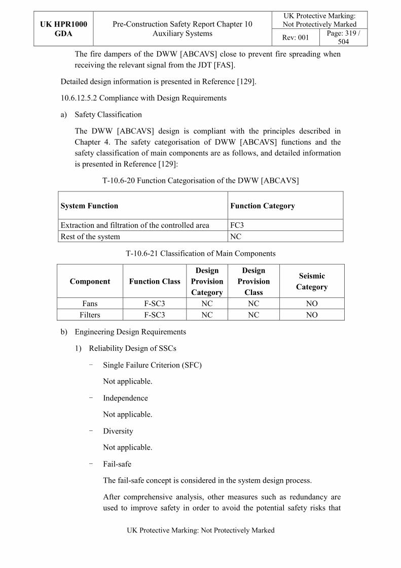
UK HPR1000
GDA
Pre-Construction Safety Report Chapter 10 Auxiliary Systems
UK Protective Marking: Not Protectively Marked
Rev: 001 Page: 319 /
504
UK Protective Marking: Not Protectively Marked
The fire dampers of the DWW [ABCAVS] close to prevent fire spreading when receiving the relevant signal from the JDT [FAS].
Detailed design information is presented in Reference [129].
10.6.12.5.2 Compliance with Design Requirements
a) Safety Classification
The DWW [ABCAVS] design is compliant with the principles described in Chapter 4. The safety categorisation of DWW [ABCAVS] functions and the safety classification of main components are as follows, and detailed information is presented in Reference [129]:
T-10.6-20 Function Categorisation of the DWW [ABCAVS]
System Function Function Category
Extraction and filtration of the controlled area FC3
Rest of the system NC
T-10.6-21 Classification of Main Components
Component Function Class Design
Provision
Category
Design
Provision
Class
Seismic
Category
Fans F-SC3 NC NC NO
Filters F-SC3 NC NC NO
b) Engineering Design Requirements
1) Reliability Design of SSCs
- Single Failure Criterion (SFC)
Not applicable.
- Independence
Not applicable.
- Diversity
Not applicable.
- Fail-safe
The fail-safe concept is considered in the system design process.
After comprehensive analysis, other measures such as redundancy are used to improve safety in order to avoid the potential safety risks that
UK HPR1000
GDA
Pre-Construction Safety Report Chapter 10 Auxiliary Systems
UK Protective Marking: Not Protectively Marked
Rev: 001 Page: 320 /
504
UK Protective Marking: Not Protectively Marked
may be introduced by “fail-safe” design on power plant.
- Aging and Degradation
The plant design life is 60 years. Some components to be replaced at the end of their individual design life. For example, the design life of border filters is designed to be no less than 60 years. For the filter design, vibration ageing and radiation ageing are taken into consideration.
2) Human Factors
The system design of the DWW [ABCAVS] does not require short term operator intervention, however there are operator actions during plant normal operation, the effect of which needs to be estimated. The fans and filters are located in the air exhaust room controlled area, where the equipment layout facilitates their maintenance. The DWW [ABCAVS] is controlled and monitored in the main control room. It is designed to be easy for the operator to control.
3) Autonomy
Not applicable.
4) Other Design Requirements
- Prevention of Harmful Interactions of Systems Important to Safety
Not applicable.
- Considerations Related to the Electrical Power Grid
The functionality of items important to safety in the DWW [ABCAVS] is not compromised by disturbances in the electrical power grid. Detailed design information of the electrical power grid is presented in Reference [125].
c) Equipment Qualification
All the components of the DWW [ABCAVS] required performing safety functions are capable of operating under normal conditions. Principles of equipment qualification classification of the system are presented in Reference [129]. Detailed information related to the system equipment qualification is presented in Reference [125].
d) Protection Design against Internal and External Hazards
The HVAC systems comply with the requirements of external and internal hazards stated in Sub-chapter 10.2.4, for ventilation system, the corresponding protection measures of earthquake and internal fire are described as below.
UK HPR1000
GDA
Pre-Construction Safety Report Chapter 10 Auxiliary Systems
UK Protective Marking: Not Protectively Marked
Rev: 001 Page: 321 /
504
UK Protective Marking: Not Protectively Marked
1) External hazards
- Earthquake
The seismic category for the components of the DWW [ABCAVS] is NC.
2) Internal hazards
- Internal Fire
The fire rating of the duct is same as the fire barrier when it passes through the barrier, if not, fire dampers are equipped in the duct. The fire rating of the duct is achieved by fireproof wrap.
Specific protection measures of other hazards are presented in Reference [127].
e) Commissioning
Commissioning and tests shall be carried out to validate the system’s functionality. The methodology of system commissioning programme design is presented in Reference [31]. Further detailed site specific arrangements for the UK HPR1000 commissioning activities will be presented during the nuclear site licencing phase in conjunction with the site licensee.
f) Examination, Inspection, Maintenance and Testing
1) Examination and Inspection
There is no equipment of the DWW [ABCAVS] requiring in-service inspection.
The combined information of the DWW [ABCAVS] displayed in the Main Control Room (MCR) for the operator includes:
- Differential pressure of filters;
- Differential pressure of fans.
2) Maintenance
During the normal operating conditions, the DWW [ABCAVS] should provide ventilation and cooling for the controlled areas of the access building. As there are three filtration trains, each sized for 50% of the flow rate and two fan trains, each sized for 100% of the flow rate in the DWW [ABCAVS], one filtration train and one fan train can be maintained during normal operation of the plant.
3) Periodic Tests
Not applicable.
UK HPR1000
GDA
Pre-Construction Safety Report Chapter 10 Auxiliary Systems
UK Protective Marking: Not Protectively Marked
Rev: 001 Page: 322 /
504
UK Protective Marking: Not Protectively Marked
g) Decommissioning
Decommissioning considerations are taken into account of system design. The principles are given in SDM chapter 3, Reference [129].
h) Material Selection
Equipment in contact with outside air is protected against corrosion due to the saline atmosphere by a coating of paint.
The entire DWW [ABCAVS] equipment is made of carbon steel.
10.6.12.6 Simplified Diagrams
The simplified system diagram is presented in Figure F-10.6-10; the detailed system functional diagrams are presented in Reference [130].
10.6.13 Diesel Building Ventilation System (DVD [DBVS])
The DVD [DBVS] provides ventilation for the diesel building. Information of the system is presented in the SDM chapter 2, Reference [132].
10.6.13.1 Safety Functional Requirements
10.6.13.1.1 Control of Reactivity
The DVD [DBVS] does not contribute to this safety function.
10.6.13.1.2 Removal of Heat
The DVD [DBVS] does not contribute to this safety function.
10.6.13.1.3 Confinement
The DVD [DBVS] does not contribute to the confinement of radioactive substances.
10.6.13.1.4 Extra Safety Functions
With respect to its contribution to the extra functions, the DVD [DBVS] must satisfy the following requirements:
a) Supporting The Fundamental Safety Functions
The DVD [DBVS] provide acceptable ambient conditions for safety classified equipment in three trains of emergency diesel generator buildings and two trains of SBO diesel generator buildings (trains A and B) during plant normal conditions and plant accident conditions.
b) Prevent, Protect and Mitigate Hazards Impact
1) Fire
The DVD [DBVS] must prevent fire from affecting the operation of
UK HPR1000
GDA
Pre-Construction Safety Report Chapter 10 Auxiliary Systems
UK Protective Marking: Not Protectively Marked
Rev: 001 Page: 323 /
504
UK Protective Marking: Not Protectively Marked
safety-related equipment and safety of staff in the Diesel Generator Buildings (BDX).
2) External Explosion
The DVD [DBVS] must prevent external explosions from affecting the operation of safety-related equipment located in the BDX.
10.6.13.2 Design Requirements
The general design requirements of the HVAC systems which need to be considered are shown in Sub-chapter 10.2.4, among which the following requirements are not applicable for the DVD [DBVS]:
a) Autonomy in Respect of the Heat Sink
Not applicable, because the DVD [DBVS] doesn’t provide a heat sink to the power plant.
b) Autonomy in Respect of Power Supply Systems
Not applicable, because the DVD [DBVS] doesn’t provide a power supply to the power plant.
c) Prevention of Harmful Interactions of Systems Important to Safety
Not applicable, because the DVD [DBVS] doesn’t have harmful interactions of systems important to safety.
The substantiation analysis of the DVD [DBVS] to other design requirements is shown in the Sub-chapter 10.6.13.5.2.
10.6.13.3 Design Bases
10.6.13.3.1 General Assumptions
a) For each diesel building division, an air conditioning subsystem is designed to cool the electrical room and a ventilation subsystem for the diesel generator room.
b) The air conditioning train operates during plant normal operation and plant accident conditions.
10.6.13.3.2 Design Assumptions
a) Control of Reactivity
Not applicable. The DVD [DBVS] does not directly contribute to the safety function of control of reactivity.
b) Removal of Heat
UK HPR1000
GDA
Pre-Construction Safety Report Chapter 10 Auxiliary Systems
UK Protective Marking: Not Protectively Marked
Rev: 001 Page: 324 /
504
UK Protective Marking: Not Protectively Marked
Not applicable. The DVD [DBVS] does not directly contribute to the safety function of removal of heat.
c) Confinement
The DVD [DBVS] does not directly contribute to the safety function of confinement.
d) Extra Safety Functions
1) Supporting The Fundamental Safety Functions
The capacity of the ventilation subsystem considers the following assumptions:
- The external conditions to be taken into account for the DVD [DBVS] are defined in Table T-10.6-41.
- The internal conditions to be taken into account for the DVD [DBVS] are defined in Tables T-10.6-43 and T-10.6-44.
- The capacity of the air conditioning subsystem considers the maximum heat dissipation of the equipment and pipes under plant normal operation and plant accident conditions.
- The capacity of the ventilation subsystem considers the maximum heat dissipation of the equipment and pipes under plant normal operation and plant accident conditions.
2) Prevent, Protect and Mitigate Hazards Impact
- Fire
The fire dampers must be closed automatically when air temperature is
higher than 70℃.
- External Explosion
The parameters of external explosions which must be taken into consideration are given in Chapter 18 (External Hazards).
10.6.13.4 System Description and Operation
10.6.13.4.1 System Description
a) General System Description
The DVD [DBVS] provides ventilation for three trains of emergency diesel generator buildings and two trains of SBO diesel generator buildings (trains A and B).
For each diesel generator building, the rooms have their own ventilation system
UK HPR1000
GDA
Pre-Construction Safety Report Chapter 10 Auxiliary Systems
UK Protective Marking: Not Protectively Marked
Rev: 001 Page: 325 /
504
UK Protective Marking: Not Protectively Marked
with no connection to the other divisions.
The DVD [DBVS] of each diesel generator building consists of the following independent subsystems:
1) Ventilation of Diesel Hall:
- Air inlet with Explosion Pressure Wave (EPW) dampers, silencers and filter;
- 2×50% capacity air supply fans;
- 2×50% capacity exhaust fans;
- 3×33% Fan heater units;
- Exhaust outlet with EPW dampers and silencers.
2) Air conditioning of the electrical room and control room:
- Air inlet;
- An air handling unit (containing: pre-filter, fine filter, electric heater, cooling coil with an independent heat sink and one air supply fan);
- Ductwork (supply and recycled air).
3) Ventilation of fuel tank rooms:
- Air inlet (from the diesel hall to the daily fuel tank room and main fuel tank room);
- Exhaust fan with 100% capacity.
Detailed information of the systems is presented in the SDM, Reference [131].
b) Description of Main Equipment
1) Fans
The fans of the ventilation subsystem are axial and the fans in air handling units are centrifugal, all of them are a direct-coupled drive type.
2) Air handling units
The air handling units are designed to manage air, they consist of pre-filters, fine filters, electric heaters, cooling coils and fans.
- Cooling Coils
The coils are made of copper tubes with several passes depending on the thermal characteristics, with copper or aluminium fins. The frames are made of galvanised steel or stainless steel.
UK HPR1000
GDA
Pre-Construction Safety Report Chapter 10 Auxiliary Systems
UK Protective Marking: Not Protectively Marked
Rev: 001 Page: 326 /
504
UK Protective Marking: Not Protectively Marked
- Electrical Heaters
The electric heaters are designed to maintain the air temperature by heating the air and are comprised of reinforced tubular elements placed in a sheet metal box made of galvanised steel.
- Pre-filters
The pre-filters are designed to filter dust in the air and their efficiency is more than 85% (weighting method).
- Fine Filters
The fine filters are designed to filter dust and their efficiency is more than 90% (counting method).
3) Isolation Dampers
The isolation dampers are designed to ensure the isolation of air supply and exhaust in the BDX.
Detailed information of the equipment design is presented in the SDM chapter 4, Reference [131].
c) Description of Main Layout
The main equipment of each DVD [DBVS] train is located in the corresponding diesel generator building.
Detailed design information about the system layout is presented in the SDM, Reference [133].
d) Description of System Interfaces
The DVD [DBVS] is connected to the following mechanical systems (not including power supplies and I&C systems):
1) JDT [FAS]
This system provides signals to the fire dampers of the DVD [DBVS].
2) SEH [WONWDS]
This system collects drainage water from the DVD [DBVS] air handling unit.
Detailed information of the interface systems is presented in the SDM, Reference [131].
e) Description of Instrumentation and Control
Instruments controlling and monitoring the DVD [DBVS] and displaying of the actuator are provided in the MCR.
UK HPR1000
GDA
Pre-Construction Safety Report Chapter 10 Auxiliary Systems
UK Protective Marking: Not Protectively Marked
Rev: 001 Page: 327 /
504
UK Protective Marking: Not Protectively Marked
Detailed information of the system I&C design is presented in the SDM, Reference [134].
10.6.13.4.2 System Operation
a) Plant Normal Conditions
During plant normal operation, the air conditioning of electrical room and control rooms operates continuously, and the ventilation of the fuel tank rooms operates continuously.
The air conditioning train also serves the diesel hall through the transfer duct.
b) Plant Accident Conditions
1) Loss of Offsite Power (LOOP)
In the event of LOOP, the ventilation of the EDG diesel hall and the air conditioning of electrical rooms are operational.
2) Station Black Out (SBO)
In the event of a SBO, the ventilation of the SBO diesel hall and the air conditioning of electrical rooms are operational.
10.6.13.5 Preliminary Design Substantiation
In this sub-chapter, the system design is demonstrated to satisfy the safety functional requirements presented in Sub-chapter 10.6.13.1 and the general design requirements stated in Sub-chapter 10.2.4. Review of the consistency of the system design against the newly developed principles is currently being undertaken.
10.6.13.5.1 Compliance with Safety Functional Requirements
a) Control of Reactivity
Not applicable.
b) Removal of Heat
Not applicable.
c) Confinement
Not applicable.
d) Extra Safety Functions
1) Supporting The Fundamental Safety Functions
The DVD [DBVS] components are sized to meet the cooling requirements of equipment in the BDX under all summer and winter conditions as defined in Table T-10.6-41.
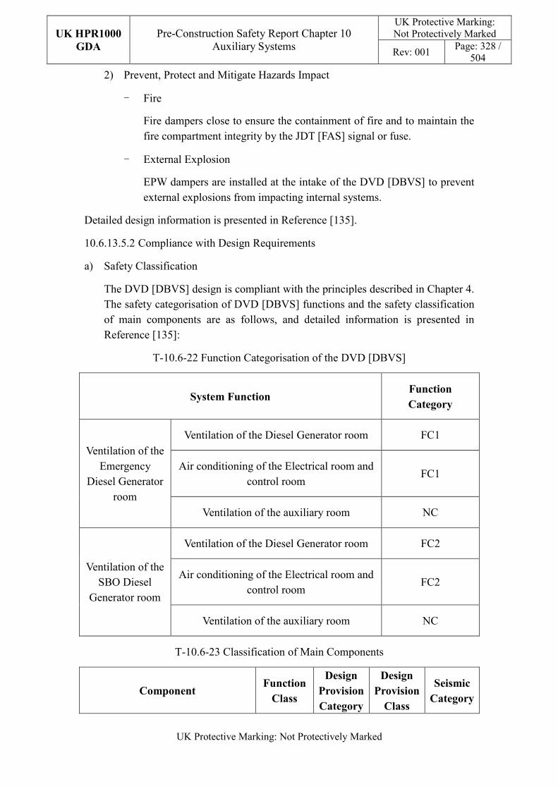
UK HPR1000
GDA
Pre-Construction Safety Report Chapter 10 Auxiliary Systems
UK Protective Marking: Not Protectively Marked
Rev: 001 Page: 328 /
504
UK Protective Marking: Not Protectively Marked
2) Prevent, Protect and Mitigate Hazards Impact
- Fire
Fire dampers close to ensure the containment of fire and to maintain the fire compartment integrity by the JDT [FAS] signal or fuse.
- External Explosion
EPW dampers are installed at the intake of the DVD [DBVS] to prevent external explosions from impacting internal systems.
Detailed design information is presented in Reference [135].
10.6.13.5.2 Compliance with Design Requirements
a) Safety Classification
The DVD [DBVS] design is compliant with the principles described in Chapter 4. The safety categorisation of DVD [DBVS] functions and the safety classification of main components are as follows, and detailed information is presented in Reference [135]:
T-10.6-22 Function Categorisation of the DVD [DBVS]
System Function Function
Category
Ventilation of the Emergency
Diesel Generator room
Ventilation of the Diesel Generator room FC1
Air conditioning of the Electrical room and control room
FC1
Ventilation of the auxiliary room NC
Ventilation of the SBO Diesel
Generator room
Ventilation of the Diesel Generator room FC2
Air conditioning of the Electrical room and control room
FC2
Ventilation of the auxiliary room NC
T-10.6-23 Classification of Main Components
Component Function
Class
Design
Provision
Category
Design
Provision
Class
Seismic
Category
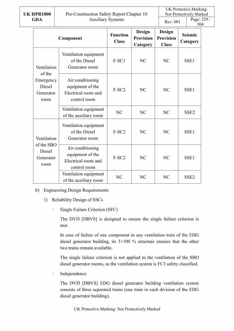
UK HPR1000
GDA
Pre-Construction Safety Report Chapter 10 Auxiliary Systems
UK Protective Marking: Not Protectively Marked
Rev: 001 Page: 329 /
504
UK Protective Marking: Not Protectively Marked
Component Function
Class
Design
Provision
Category
Design
Provision
Class
Seismic
Category
Ventilation of the
Emergency Diesel
Generator room
Ventilation equipment of the Diesel
Generator room F-SC1 NC NC SSE1
Air conditioning equipment of the
Electrical room and control room
F-SC2 NC NC SSE1
Ventilation equipment of the auxiliary room
NC NC NC SSE2
Ventilation of the SBO
Diesel Generator
room
Ventilation equipment of the Diesel
Generator room F-SC2 NC NC SSE1
Air conditioning equipment of the
Electrical room and control room
F-SC2 NC NC SSE1
Ventilation equipment of the auxiliary room
NC NC NC SSE2
b) Engineering Design Requirements
1) Reliability Design of SSCs
- Single Failure Criterion (SFC)
The DVD [DBVS] is designed to ensure the single failure criterion is met.
In case of failure of one component in any ventilation train of the EDG diesel generator building, its 3×100 % structure ensures that the other two trains remain available.
The single failure criterion is not applied to the ventilation of the SBO diesel generator rooms, as the ventilation system is FC3 safety classified.
- Independence
The DVD [DBVS] EDG diesel generator building ventilation system consists of three separated trains (one train in each division of the EDG diesel generator building).
UK HPR1000
GDA
Pre-Construction Safety Report Chapter 10 Auxiliary Systems
UK Protective Marking: Not Protectively Marked
Rev: 001 Page: 330 /
504
UK Protective Marking: Not Protectively Marked
The DVD [DBVS] SBO diesel generator building ventilation system consists of two separated trains (one train in each division of the SBO diesel generator building).
- Diversity
Not applicable.
- Fail-safe
The fail-safe concept is considered in the system design process.
After comprehensive analysis, other measures such as redundancy are used to improve safety in order to avoid the potential safety risks that may be introduced by “fail-safe” design on power plant.
- Ageing and Degradation
The plant design life is 60 years. Some components to be replaced at the end of their individual design life. For the fan design, vibration ageing and thermal ageing are taken into consideration. The differential pressure of the fan is monitored and recorded in real time, which is convenient for the operator to assess the performance of the fan.
2) Human Factors
The system design of the DVD [DBVS] does not require short term operator intervention, however there are operator actions during plant normal operation, the effect of which needs to be estimated. The fan and filter of each DVD [DBVS] train are located in adjacent equipment rooms, where the equipment layout facilitates their maintenance. The DVD [DBVS] is controlled and monitored in the main control room. It is designed to be easy for the operator to control.
3) Autonomy
- Autonomy in Respect of Operators
The design principles relevant to the autonomy in respect of operators are detailed in Sub-chapter 10.2.4. The design of the DVD [DBVS] fulfils these principles via control functional design; the detailed information is presented in SDM, Reference [134]. The design result is estimated in the safety analysis.
- Autonomy in Respect of the Heat Sink
The design principles relevant to the autonomy in respect of the heat sink are not applicable for DVD [DBVS] design.
- Autonomy in Respect of Power Supply Systems
UK HPR1000
GDA
Pre-Construction Safety Report Chapter 10 Auxiliary Systems
UK Protective Marking: Not Protectively Marked
Rev: 001 Page: 331 /
504
UK Protective Marking: Not Protectively Marked
The design principles relevant to the autonomy in respect of the power supply are not applicable for DVD [DBVS] design.
4) Other Design Requirements
- Prevention of Harmful Interactions of Systems Important to Safety
Not applicable.
- Considerations Related to the Electrical Power Grid
The functionality of items important to safety in the DVD [DBVS] is not compromised by disturbances in the electrical power grid. Detailed design information of the electrical power grid is presented in Reference [131].
c) Equipment Qualification
All the safety classified components of the DVD [DBVS] required to perform safety functions are capable of operating under both normal and accident conditions. As a result, the components can withstand the most adverse environmental conditions expected.
All the seismically classified components of the DVD [DBVS] shall be capable of operating during and after the SSE. The components are seismically designed and qualified for the SSE loads.
Detailed equipment qualification classification of the system is presented in Reference [135]. Detailed information related to the system equipment qualification is presented in Reference [131].
d) Protection Design against Internal and External Hazards
The HVAC systems comply with the requirements of external and internal hazards stated in Sub-chapter 10.2.4, for ventilation system, the corresponding protection measures of earthquake and internal fire are described as below.
1) External hazards
- Earthquake
The seismic category for the components of the DVD [DBVS] performing Safety Category 1 (FC1) and Safety Category 2 (FC2) is Seismic Category 1 (SSE1).
2) Internal hazards
- Internal Fire
The fire rating of the duct is same as the fire barrier when it passes through the barrier, if not, fire dampers are equipped in the duct. The fire
UK HPR1000
GDA
Pre-Construction Safety Report Chapter 10 Auxiliary Systems
UK Protective Marking: Not Protectively Marked
Rev: 001 Page: 332 /
504
UK Protective Marking: Not Protectively Marked
rating of the duct is achieved by fireproof wrap.
Specific protection measures of other hazards are presented in Reference [133].
e) Commissioning
Commissioning and tests shall be carried out to validate the system’s functionality. The methodology of system commissioning programme design is presented in Reference [31]. Further detailed site specific arrangements for the UK HPR1000 commissioning activities will be presented during the nuclear site licencing phase in conjunction with the site licensee.
f) Examination, Inspection, Maintenance and Testing
1) Examination and Inspection
There is no equipment of the DVD [DBVS] requiring in-service inspection.
The combined information of the DVD [DBVS] displayed in the Main Control Room (MCR) for the operator includes:
- Temperature in the Diesel generator rooms;
- Air supply temperature of the electrical room air conditioning subsystem;
- Temperature in each of the control and electrical rooms.
2) Maintenances
Maintenance can be done when the corresponding served equipment is in maintenance during shutdown of plant.
3) Periodic Tests
For the UK HPR1000, the periodic test design method is presented in the Reference [32]. FC1, FC2 and FC3 equipment should be tested if they are not in continuous operation. Some equipment performing safety functions shall be subject to periodic testing, including:
Availability of the diesel hall fans for the EDG buildings.
g) Decommissioning
Decommissioning considerations are taken into account of system design. The principles are given in SDM chapter 3, Reference [135].
h) Material Selection
The duct material is galvanised steel.
UK HPR1000
GDA
Pre-Construction Safety Report Chapter 10 Auxiliary Systems
UK Protective Marking: Not Protectively Marked
Rev: 001 Page: 333 /
504
UK Protective Marking: Not Protectively Marked
10.6.13.6 Simplified Diagrams
The simplified system diagram is presented in Figure F-10.6-11; the detailed system functional diagrams are presented in Reference [136].
10.6.14 Essential Service Water Pumping Station Ventilation System (DXS
[ESWVS])
The DXS [ESWVS] provides ventilation for the essential service water pumping station.
10.6.14.1 Safety Functional Requirements
10.6.14.1.1 Control of Reactivity
The DXS [ESWVS] does not contribute to this safety function.
10.6.14.1.2 Removal of Heat
The DXS [ESWVS] does not contribute to this safety function.
10.6.14.1.3 Confinement
The DXS [ESWVS] does not contribute to this safety function.
10.6.14.1.4 Extra Safety Functions
With respect to its contribution to the extra safety functions, the DXS [ESWVS] must satisfy the following requirements:
a) Supporting the Fundamental Safety Functions
The DXS [ESWVS] provides the acceptable ambient conditions for safety classified equipment in the essential service water pumping station during plant normal conditions and plant accident conditions.
b) Prevent, Protect and Mitigate Hazards Impact
1) Fire
The DXS [ESWVS] must prevent fire from affecting the operation of safety-related equipment.
2) External Explosion
The DXS [ESWVS] must prevent external explosions from affecting the operation of safety-related equipment located in the essential service water pumping station.
10.6.14.2 Design Requirements
The general design requirements of the HVAC systems which need to be considered are shown in Sub-chapter 10.2.4, among which the following requirements are not
UK HPR1000
GDA
Pre-Construction Safety Report Chapter 10 Auxiliary Systems
UK Protective Marking: Not Protectively Marked
Rev: 001 Page: 334 /
504
UK Protective Marking: Not Protectively Marked
applicable for the DXS [ESWVS]:
a) Autonomy in Respect of the Heat Sink
Not applicable, because the DXS [ESWVS] doesn’t provide a heat sink to the power plant.
b) Autonomy in Respect of Power Supply Systems
Not applicable, because the DXS [ESWVS] doesn’t provide a power supply to the power plant.
c) Prevention of Harmful Interactions of Systems Important to Safety
Not applicable, because the DXS [ESWVS] doesn’t have harmful interactions of systems important to safety.
The substantiation analysis of the DXS [ESWVS] to other design requirements is shown in the Sub-chapter 10.6.14.5.2.
10.6.14.3 Design Bases
10.6.14.3.1 General Assumptions
For each essential service water pumping station division, there is a 100% ventilation train.
10.6.14.3.2 Design Assumptions
a) Control of Reactivity
Not applicable. The DXS [ESWVS] does not directly contribute to the safety function of control of reactivity.
b) Removal of Heat
Not applicable. The DXS [ESWVS] does not directly contribute to the safety function of removal of heat.
c) Confinement
Not applicable. The DXS [ESWVS] does not directly contribute to the safety function of confinement.
d) Extra Safety Functions
1) Supporting the Fundamental Safety Functions
- The internal conditions to be taken into account for the DXS [ESWVS] are defined in Tables T-10.6-43 and T-10.6-44.
- The external conditions to be taken into account for the DXS [ESWVS] are defined in Table T-10.6-41.
UK HPR1000
GDA
Pre-Construction Safety Report Chapter 10 Auxiliary Systems
UK Protective Marking: Not Protectively Marked
Rev: 001 Page: 335 /
504
UK Protective Marking: Not Protectively Marked
- The capacity of the DXS [ESWVS] considers the maximum heat load of the equipment and lighting.
2) Prevent, Protect and Mitigate Hazards Impact
- Fire
The fire dampers must be closed automatically when air temperature is
higher than 70℃.
- External explosion
The parameters of external explosions which must be taken into consideration are given in Chapter 18 (External Hazards).
e) Other Assumptions
Not applicable. There’s no quantitative design assumption for the DXS [ESWVS].
10.6.14.4 System Description and Operation
10.6.14.4.1 System Description
The DXS [ESWVS] is made up of three trains. Train A and B are configured with two 100% capacity sub ventilation trains, and train C is configured with a 100% capacity ventilation train.
a) General System Description
Each DXS [ESWVS] sub train consists of the following:
1) Supply air train-100% each (an EPW damper, pre-filter, a fan);
2) Exhaust air train-100% each (an EPW damper, a manual damper);
3) Duct network and a set of accessory.
b) Description of Main Equipment
1) Fans
The fans are axial and a direct-coupled drive type.
2) Pre-filters
The pre-filters are designed to filter dust in the air and their efficiency is more than 85% (weighting method).
c) Description of Main Layout
The main equipment of each DXS [ESWVS] train is located in the corresponding essential service water pumping station.
UK HPR1000
GDA
Pre-Construction Safety Report Chapter 10 Auxiliary Systems
UK Protective Marking: Not Protectively Marked
Rev: 001 Page: 336 /
504
UK Protective Marking: Not Protectively Marked
d) Description of System Interfaces
The DXS [ESWVS] is connected to the following mechanical systems (not including power supplies and I&C systems):
The JDT [FAS] provides signals to the fire dampers of the DXS [ESWVS].
e) Description of Instrumentation and Control
Instruments controlling and monitoring the DXS [ESWVS] and displaying of the actuator are provided in the MCR.
10.6.14.4.2 System Operation
a) Plant Normal Conditions
If the temperature of the SEC [ESWS] Pump station is higher than 30°C, the supply and exhaust fans of the corresponding train shall be started.
b) Plant Accident Conditions
In the LOOP event, the DXS [ESWVS] should operate when the SEC [ESWS] pump is used.
10.6.14.5 Preliminary Design Substantiation
In this sub-chapter, the system design is demonstrated to satisfy the safety functional requirements presented in Sub-chapter 10.6.14.1 and the general design requirements stated in Sub-chapter 10.2.4. Review of the consistency of the system design against the newly developed principles is currently being undertaken.
10.6.14.5.1 Compliance with Safety Functional Requirements
a) Control of Reactivity
Not applicable.
b) Removal of Heat
Not applicable.
c) Confinement
Not applicable.
d) Extra Safety Functions
1) Supporting the Fundamental Safety Functions
The DXS [ESWVS] components are sized to meet the cooling requirements of equipment in the SEC [ESWS] pump station under all summer and winter conditions as defined in Table T-10.6-41.
UK HPR1000
GDA
Pre-Construction Safety Report Chapter 10 Auxiliary Systems
UK Protective Marking: Not Protectively Marked
Rev: 001 Page: 337 /
504
UK Protective Marking: Not Protectively Marked
2) Prevent, Protect and Mitigate Hazards Impact
- Fire
Fire dampers are designed on the boundary of the fire compartment, which is closed by the JDT [FAS] signal or damper fuse in case of a fire.
- External explosion
The EPW dampers which are installed in the intake of the DXS [ESWVS] close to prevent external explosions from affecting internal systems.
10.6.14.5.2 Compliance with Design Requirements
a) Safety Classification
The DXS [ESWVS] design is compliant with the principles described in Chapter 4. The safety categorisation of DXS [ESWVS] functions and the safety classification of main components are as follows:
T-10.6-24 Function Categorisation of the DXS [ESWVS]
System Function Function Category
Ventilation for the SEC [ESWS] pump rooms FC1
The others NC
T-10.6-25 Classification of Main Components
Component Function
Class
Design
Provision
Category
Design
Provision
Class
Seismic
Category
Ventilation equipment for the
SEC [ESWS] pump rooms
F-SC1 NC NC SSE1
The other equipment NC NC NC SSE2/NO
b) Engineering Design Requirements
1) Reliability Design of SSCs
- Single Failure Criterion (SFC)
The DXS [ESWVS] performs FC1 safety functions. The DXS [ESWVS] must be designed to consider credible single failures. Therefore, 3×100%
UK HPR1000
GDA
Pre-Construction Safety Report Chapter 10 Auxiliary Systems
UK Protective Marking: Not Protectively Marked
Rev: 001 Page: 338 /
504
UK Protective Marking: Not Protectively Marked
independent air conditioning trains are provided.
- Independence
The DXS [ESWVS] system consists of three separate trains.
- Diversity
Not applicable.
- Fail-safe
There’s no fail-safe designed equipment in the DXS [ESWVS].
- Ageing and Degradation
The plant design life is 60 years. Some components to be replaced at the end of their individual design life. For the fan design, vibration ageing and thermal ageing are taken into consideration. The differential pressure of the fan is monitored and recorded in real time, which is convenient for the operator to assess of the performance of the fan.
2) Human Factors
The system design of the DXS [ESWVS] does not require short term operator intervention, however there are operator actions during plant normal operation, the effect of which needs to be estimated. The fan and filter of each DXS [ESWVS] train are located in adjacent equipment rooms, where the equipment layout facilitates their maintenance. The DXS [ESWVS] is controlled and monitored in the main control room. It is designed to be easy for the operator to control.
3) Autonomy
- Autonomy in Respect of Operators
The design principles relevant to the autonomy in respect of operators are detailed in Sub-chapter 10.2.4. The design of the DXS [ESWVS] fulfils these principles via control functional design. The design result is estimated in the safety analysis.
- Autonomy in Respect of the Heat Sink
The design principles relevant to the autonomy in respect of the heat sink are not applicable for DXS [ESWVS] design.
- Autonomy in Respect of Power Supply Systems
The design principles relevant to the autonomy in respect of the power supply are not applicable for DXS [ESWVS] design.
UK HPR1000
GDA
Pre-Construction Safety Report Chapter 10 Auxiliary Systems
UK Protective Marking: Not Protectively Marked
Rev: 001 Page: 339 /
504
UK Protective Marking: Not Protectively Marked
4) Other Design Requirements
- Prevention of Harmful Interactions of Systems Important to Safety
Not applicable.
- Considerations Related to the Electrical Power Grid
The functionality of items important to safety in the DXS [ESWVS] is not compromised by disturbances in the electrical power grid.
c) Equipment Qualification
All the components of the DXS [ESWVS] required performing safety functions are capable of operating under both normal and accident conditions. As a result, the components can withstand the most adverse environmental conditions expected.
All the seismically classified components of the DXS [ESWVS] shall be capable of operating during and after the SSE. The components are seismically designed and qualified for the SSE loads.
d) Protection Design against Internal and External Hazards
The HVAC systems comply with the requirements of external and internal hazards stated in Sub-chapter 10.2.4, for ventilation system, the corresponding protection measures of earthquake and internal fire are described as below.
1) External hazards
- Earthquake
The seismic category for the components of the DXS [ESWVS] performing Safety Category 1 (FC1) and Safety Category 2 (FC2) is Seismic Category 1 (SSE1).
2) Internal hazards
- Internal Fire
The fire rating of the duct is same as the fire barrier when it passes through the barrier, if not, fire dampers are equipped in the duct. The fire rating of the duct is achieved by fireproof wrap.
e) Commissioning
Commissioning shall be carried out for the DXS [ESWVS] to validate its functionality.
f) Examination, Inspection, Maintenance and Testing
1) Examination and Inspection
UK HPR1000
GDA
Pre-Construction Safety Report Chapter 10 Auxiliary Systems
UK Protective Marking: Not Protectively Marked
Rev: 001 Page: 340 /
504
UK Protective Marking: Not Protectively Marked
There is no equipment of the DXS [ESWVS] requiring in-service inspection.
The information of the DXS [ESWVS] displayed in the Main Control Room (MCR) for the operator consists of the temperature in the rooms.
2) Maintenances
Maintenance can be done when the corresponding served equipment is in maintenance during shutdown of plant.
3) Periodic Tests
Because of continuous operation, there is no requirement of periodic testing for equipment of the DXS [ESWVS].
g) Decommissioning
Decommissioning considerations are taken into account of system design.
h) Material Selection
The duct material is galvanised steel.
10.6.14.6 Simplified Diagrams
The simplified system diagram is presented in Figure F-10.6-12.
10.6.15 Extra Cooling Water and NI Firefighting Building Ventilation System
(DXE [ECW&FFB VS])
The DXE [ECW&FFB VS] provides ventilation for extra cooling water and the NI firefighting building. Information of the system is presented in the SDM chapter 2, Reference [138].
10.6.15.1 Safety Functional Requirements
10.6.15.1.1 Control of Reactivity
The DXE [ECW&FFB VS] does not contribute to this safety function.
10.6.15.1.2 Removal of Heat
The DXE [ECW&FFB VS] does not contribute to this safety function.
10.6.15.1.3 Confinement
The DXE [ECW&FFB VS] does not contribute to this safety function.
10.6.15.1.4 Extra Safety Functions
With respect to its contribution to the extra safety functions, the DXE [ECW&FFB VS] must satisfy the following requirements:
a) Supporting The Fundamental Safety Functions
UK HPR1000
GDA
Pre-Construction Safety Report Chapter 10 Auxiliary Systems
UK Protective Marking: Not Protectively Marked
Rev: 001 Page: 341 /
504
UK Protective Marking: Not Protectively Marked
The DXE [ECW&FFB VS] provide the acceptable ambient conditions for safety classified equipment in the extra cooling water and NI firefighting building during plant normal conditions and plant accident conditions.
b) Prevent, Protect and Mitigate Hazard Impact
Not applicable.
10.6.15.2 Design Requirements
The general design requirements of the HVAC systems which need to be considered are shown in Sub-chapter 10.2.4, among which the following requirements are not applicable for the DXE [ECW&FFB VS]:
a) Autonomy in Respect of Operators
Not applicable, because the DXE [ECW&FFB VS] doesn’t contribute to the autonomy objective.
b) Autonomy in Respect of the Heat Sink
Not applicable, because the DXE [ECW&FFB VS] doesn’t provide a heat sink to the power plant.
c) Autonomy in Respect of Power Supply Systems
Not applicable, because the DXE [ECW&FFB VS] doesn’t provide a power supply to the power plant.
d) Prevention of Harmful Interactions of Systems Important to Safety
Not applicable, because the DXE [ECW&FFB VS] doesn’t have harmful interactions of systems important to safety.
The substantiation analysis of the DXE [ECW&FFB VS] to other design requirements is shown in the Sub-chapter 10.6.15.5.2.
10.6.15.3 Design Bases
10.6.15.3.1 General Assumptions
For each diesel building division, there is a 100% ventilation train.
10.6.15.3.2 Design Assumptions
a) Control of Reactivity
Not applicable. The DXE [ECW&FFB VS] does not directly contribute to the safety function of control of reactivity.
b) Removal of Heat
Not applicable. The DXE [ECW&FFB VS] does not directly contribute to the
UK HPR1000
GDA
Pre-Construction Safety Report Chapter 10 Auxiliary Systems
UK Protective Marking: Not Protectively Marked
Rev: 001 Page: 342 /
504
UK Protective Marking: Not Protectively Marked
safety function of removal of heat.
c) Confinement
Not applicable. The DXE [ECW&FFB VS] does not directly contribute to the safety function of confinement.
d) Extra Safety Functions
1) Supporting The Fundamental Safety Functions
- The internal conditions to be taken into account for the DXE [ECW&FFB VS] are defined in Tables T-10.6-43 and T-10.6-44.
- The external conditions to be taken into account for the DXE [ECW&FFB VS] are defined in Table T-10.6-41.
- The capacity of the DXE [ECW&FFB VS] considers the maximum heat dissipation of the equipment and pipes under plant normal operation and accident conditions.
2) Prevent, Protect and Mitigate Hazards Impact
Not applicable.
10.6.15.4 System Description and Operation
10.6.15.4.1 System Description
a) General System Description
The DXE [ECW&FFB VS] is consisted of three trains. Train A and B provide services for the corresponding ECS [ECS] /JAC [FWPS] and train C provides services for JAC [FWPS] train C. Train A and B are configured with two 50% capacity fans and two 50% capacity exhaust fans, and train C is configured with a 100% capacity fan and a 100% capacity exhaust fan.
The DXE [ECW&FFB VS] consists of the following:
1) Air supply and exhaust duct network;
2) Two air supply trains - 50% each (train A and B) (including one pre-filter and fan);
3) One air supply train - 100% (train C) (including one pre-filter and fan); Two exhaust air trains - 50% each;
4) One exhaust air train - 100% (train C);
5) Dampers and a set of accessories.
Detailed information of the systems is presented in the SDM, Reference [137].
UK HPR1000
GDA
Pre-Construction Safety Report Chapter 10 Auxiliary Systems
UK Protective Marking: Not Protectively Marked
Rev: 001 Page: 343 /
504
UK Protective Marking: Not Protectively Marked
b) Description of Main Equipment
1) Fans
The fans are axial and a direct-coupled drive type.
2) Pre-filters
The pre-filters are designed to filter dust in the air and their efficiency is more than 85% (weighting method).
Detailed information of the equipment design is presented in the SDM chapter 4, Reference [137] .
c) Description of Main Layout
The main equipment of each DXE [ECW&FFB VS] train is located in the corresponding extra cooling water and NI firefighting building.
Detailed design information about the system layout is presented in the SDM, Reference [139].
d) Description of System Interfaces
The DXE [ECW&FFB VS] is connected to the following mechanical systems (not including power supplies and I&C systems):
The JDT [FAS] provides signals to the fans of the DXE [ECW&FFB VS].
Detailed information of the interface systems is presented in the SDM, Reference [137].
e) Description of Instrumentation and Control
Instruments, controlling and monitoring the DXE [ECW&FFB VS] and displaying of the actuator are provided in the MCR.
Detailed information of the system I&C design is presented in the SDM, Reference [140].
10.6.15.4.2 System Operation
a) Plant Normal Conditions
The DXE [ECW&FFB VS] operates according to the internal temperature
b) Plant Accident Conditions
If the temperature of the ECS [ECS] pump station is higher than 30°C, one of the supply and exhaust fans of the corresponding train shall be started. Furthermore, if the temperature is higher than 40°C, both of the two supply and exhaust fans shall be started.
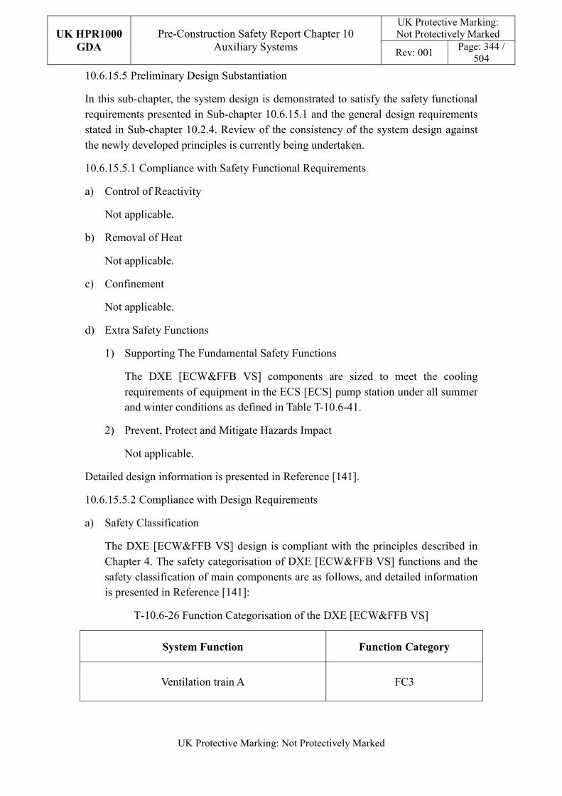
UK HPR1000
GDA
Pre-Construction Safety Report Chapter 10 Auxiliary Systems
UK Protective Marking: Not Protectively Marked
Rev: 001 Page: 344 /
504
UK Protective Marking: Not Protectively Marked
10.6.15.5 Preliminary Design Substantiation
In this sub-chapter, the system design is demonstrated to satisfy the safety functional requirements presented in Sub-chapter 10.6.15.1 and the general design requirements stated in Sub-chapter 10.2.4. Review of the consistency of the system design against the newly developed principles is currently being undertaken.
10.6.15.5.1 Compliance with Safety Functional Requirements
a) Control of Reactivity
Not applicable.
b) Removal of Heat
Not applicable.
c) Confinement
Not applicable.
d) Extra Safety Functions
1) Supporting The Fundamental Safety Functions
The DXE [ECW&FFB VS] components are sized to meet the cooling requirements of equipment in the ECS [ECS] pump station under all summer and winter conditions as defined in Table T-10.6-41.
2) Prevent, Protect and Mitigate Hazards Impact
Not applicable.
Detailed design information is presented in Reference [141].
10.6.15.5.2 Compliance with Design Requirements
a) Safety Classification
The DXE [ECW&FFB VS] design is compliant with the principles described in Chapter 4. The safety categorisation of DXE [ECW&FFB VS] functions and the safety classification of main components are as follows, and detailed information is presented in Reference [141]:
T-10.6-26 Function Categorisation of the DXE [ECW&FFB VS]
System Function Function Category
Ventilation train A FC3
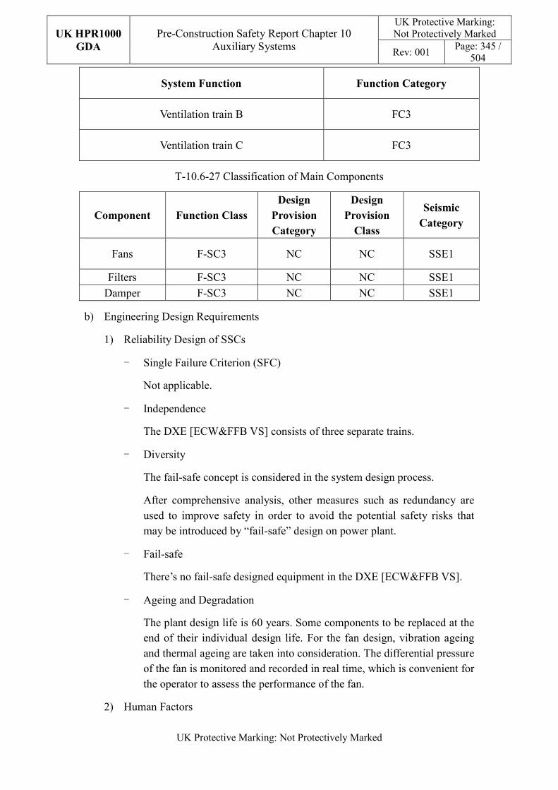
UK HPR1000
GDA
Pre-Construction Safety Report Chapter 10 Auxiliary Systems
UK Protective Marking: Not Protectively Marked
Rev: 001 Page: 345 /
504
UK Protective Marking: Not Protectively Marked
System Function Function Category
Ventilation train B FC3
Ventilation train C FC3
T-10.6-27 Classification of Main Components
Component Function Class
Design
Provision
Category
Design
Provision
Class
Seismic
Category
Fans F-SC3 NC NC SSE1
Filters F-SC3 NC NC SSE1
Damper F-SC3 NC NC SSE1
b) Engineering Design Requirements
1) Reliability Design of SSCs
- Single Failure Criterion (SFC)
Not applicable.
- Independence
The DXE [ECW&FFB VS] consists of three separate trains.
- Diversity
The fail-safe concept is considered in the system design process.
After comprehensive analysis, other measures such as redundancy are used to improve safety in order to avoid the potential safety risks that may be introduced by “fail-safe” design on power plant.
- Fail-safe
There’s no fail-safe designed equipment in the DXE [ECW&FFB VS].
- Ageing and Degradation
The plant design life is 60 years. Some components to be replaced at the end of their individual design life. For the fan design, vibration ageing and thermal ageing are taken into consideration. The differential pressure of the fan is monitored and recorded in real time, which is convenient for the operator to assess the performance of the fan.
2) Human Factors
UK HPR1000
GDA
Pre-Construction Safety Report Chapter 10 Auxiliary Systems
UK Protective Marking: Not Protectively Marked
Rev: 001 Page: 346 /
504
UK Protective Marking: Not Protectively Marked
The system design of DXE [ECW&FFB VS] does not require short term operator intervention, however there are operator actions during plant normal operation, the effect of which needs to be estimated. The fan and filter of each DXE [ECW&FFB VS] train are located in adjacent equipment rooms, where the equipment layout facilitates their maintenance. The DXE [ECW&FFB VS] is controlled and monitored in the main control room. It is designed to be easy for the operator to control.
3) Autonomy
- Autonomy in Respect of Operators
The design principles relevant to the autonomy in respect of operators are not applicable for DXE [ECW&FFB VS] design.
- Autonomy in Respect of the Heat Sink
The design principles relevant to the autonomy in respect of the heat sink are not applicable for DXE [ECW&FFB VS] design.
- Autonomy in Respect of Power Supply Systems
The design principles relevant to the autonomy in respect of the power supply are not applicable for DXE [ECW&FFB VS] design.
4) Other Design Requirements
- Prevention of Harmful Interactions of Systems Important to Safety
Not applicable.
- Considerations Related to the Electrical Power Grid
The functionality of items important to safety in the DXE [ECW&FFB VS] is not compromised by disturbances in the electrical power grid. Detailed design information of the electrical power grid is presented in Reference [137].
c) Equipment Qualification
All the safety classified components of the DXE [ECW&FFB VS] required to perform safety functions are capable of operating under both normal and accident conditions. As a result, the components can withstand the most adverse environmental conditions expected.
All the seismically classified components of the DXE [ECW&FFB VS] shall be capable of operating during and after the SSE. The components are seismically designed and qualified for the SSE loads.
Principles of equipment qualification classification of the system are presented in
UK HPR1000
GDA
Pre-Construction Safety Report Chapter 10 Auxiliary Systems
UK Protective Marking: Not Protectively Marked
Rev: 001 Page: 347 /
504
UK Protective Marking: Not Protectively Marked
Reference [141]. Information related to equipment qualification is presented in the Reference [137].
d) Protection Design against Internal and External Hazards
The HVAC systems comply with the requirements of external and internal hazards stated in Sub-chapter 10.2.4, for ventilation system, the corresponding protection measures of earthquake and internal fire are described as below.
1) External hazards
- Earthquake
All components of the DXE [ECW&FFB VS] are the Seismic Category 1(SSE1).
2) Internal hazards
- Internal Fire
The fire rating of the duct is same as the fire barrier when it passes through the barrier, if not, fire dampers are equipped in the duct. The fire rating of the duct is achieved by fireproof wrap.
Specific protection measures of other hazards are presented in Reference [139].
e) Commissioning
Commissioning and tests shall be carried out to validate the system’s functionality. The methodology of system commissioning programme design is presented in Reference [31]. Further detailed site specific arrangements for the UK HPR1000 commissioning activities will be presented during the nuclear site licencing phase in conjunction with the site licensee.
f) Examination, Inspection, Maintenance and Testing
1) Examination and Inspection
There is no equipment of the DXE [ECW&FFB VS] requiring in-service inspection.
The combined information of the DXE [ECW&FFB VS] displayed in the Main Control Room (MCR) for the operator includes:
Temperature in the rooms;
2) Maintenances
Maintenance can be done when the corresponding served equipment is in maintenance during shutdown of the plant.
3) Periodic Tests
UK HPR1000
GDA
Pre-Construction Safety Report Chapter 10 Auxiliary Systems
UK Protective Marking: Not Protectively Marked
Rev: 001 Page: 348 /
504
UK Protective Marking: Not Protectively Marked
For the UK HPR1000, the periodic test design method is presented in the Reference [32].
Because of the continuous operation of the system, there is no requirement for periodic testing for equipment of the DXE [ECW&FFB VS].
g) Decommissioning
Decommissioning considerations are taken into account of system design. The principles are given in SDM chapter 3, Reference [141].
h) Material Selection
The duct material is galvanised steel.
10.6.15.6 Simplified Diagrams
The simplified system diagram is presented in Figure F-10.6-13; the detailed system functional diagrams are presented in Reference [142].
10.6.16 Waste Treatment Building Ventilation System (DWQ [WTBVS])
The DWQ [WTBVS] serves the Radioactive Waste Treatment Building (BWX), maintains proper environmental conditions for equipment operation and personnel access and provides dynamic confinement for the building under normal conditions. It also keeps the building in static containment in case of multiple failures after an earthquake. Information of the system is presented in the SDM chapter 2, Reference [144].
10.6.16.1 Safety Functional Requirements
The requirements of the fundamental safety functions on DWQ [WTBVS] design for the UK HPR1000 are as identified below.
10.6.16.1.1 Control of Reactivity
The DWQ [WTBVS] does not contribute to this safety function.
10.6.16.1.2 Removal of Heat
The DWQ [WTBVS] does not contribute to this safety function.
10.6.16.1.3 Confinement
With respect to its contribution to confinement, the (DWQ [WTBVS]) must satisfy the following requirements:
a) Environmental Protection
The DWQ [WTBVS] must limit the leakage of radioactive material into the environment in normal conditions.
UK HPR1000
GDA
Pre-Construction Safety Report Chapter 10 Auxiliary Systems
UK Protective Marking: Not Protectively Marked
Rev: 001 Page: 349 /
504
UK Protective Marking: Not Protectively Marked
b) Limiting Radiological Consequences
1) Purification
To reduce the radioactivity released to the environment, the BWX controlled area exhaust air must be filtered before releasing it to the environment.
2) Dynamic Confinement
To reduce the radioactivity released to the environment, the DWQ [WTBVS] must keep the controlled area of the BWX in dynamic confinement in normal operation.
3) Static Confinement
The DWQ [WTBVS] must keep the building in static containment in case of multiple failures after an earthquake.
10.6.16.1.4 Extra Safety Functions
With respect to its contribution to the extra safety functions, the DWQ [WTBVS] must satisfy the following requirements:
a) Supporting the Fundamental Safety Functions
Maintain the acceptable temperature for safety classified equipment and personnel in the controlled areas of the BWX Buildings during normal conditions.
b) Prevent, Protect and Mitigate Hazards Impact
Fire: In case of fire, the DWQ [WTBVS] contributes to limit fire spread.
10.6.16.2 Design Requirements
The general design requirements of the HVAC systems which need to be considered are shown in Sub-chapter 10.2.4, among which the following requirements are not applicable for the DWQ [WTBVS]:
a) Autonomy in Respect of the Heat Sink
Not applicable, because the DWQ [WTBVS] doesn’t provide a heat sink to the power plant.
b) Autonomy in Respect of Power Supply Systems
Not applicable, because the DWQ [WTBVS] doesn’t provide a power supply system to the power plant.
c) Prevention of Harmful Interactions of Systems Important to Safety
Not applicable, because the DWQ [WTBVS] doesn’t have harmful interactions of systems important to safety.
UK HPR1000
GDA
Pre-Construction Safety Report Chapter 10 Auxiliary Systems
UK Protective Marking: Not Protectively Marked
Rev: 001 Page: 350 /
504
UK Protective Marking: Not Protectively Marked
The substantiation analysis of the DWQ [WTBVS] to other design requirements is shown in the Sub-chapter 10.6.16.5.2.
10.6.16.3 Design Bases
10.6.16.3.1 General Assumptions
The outside conditions to be taken into account for the DWQ [WTBVS] system are defined in Table T-10.6-42.
The controlled area ventilation adopts a once-through fresh air ventilation system. The supply system is designed as two trains. Fans are available at 2×100% while air treatment equipment is available at 2×50%. The exhaust train has four trains of filtration available at 4×33% while the exhaust fans are available at 2×100%.
The exhaust air of the DWQ [WTBVS] must be filtered to reduce its radioactivity. The filtration system is divided into three trains according to the ventilation system requirements, while another single standby train is designed considering the filter replacement.
Local electric heaters are designed for the rooms with lower temperature limits.
Local cooling units are designed for the rooms with a large quantity of heat being released.
10.6.16.3.2 Design Assumptions
a) Control of Reactivity
Not applicable. The DWQ [WTBVS] does not contribute to the safety function of control of reactivity.
b) Removal of Heat
Not applicable. The DWQ [WTBVS] does not contribute to the safety function of removal of heat.
c) Confinement
The DWQ [WTBVS] is designed to satisfy the confinement of the BWX controlled area. The functional requirements are as follows:
1) Environmental Protection
Maintain negative pressure in the controlled area of the BWX. For the specific negative pressure see Table T-10.6-36.
2) Limiting Radiological Consequences
- Dynamic Confinement
The DWQ [WTBVS] is designed so that the volume of exhaust air is
UK HPR1000
GDA
Pre-Construction Safety Report Chapter 10 Auxiliary Systems
UK Protective Marking: Not Protectively Marked
Rev: 001 Page: 351 /
504
UK Protective Marking: Not Protectively Marked
more than the supply air to maintain the controlled area at a negative pressure. This sets a pressure gradient which can ensure the air flows from low potential radioactive areas to high potential radioactive areas. For the specific negative pressure see Table T-10.6-36.
- Static Isolation
Isolating dampers are designed in the opening to the controlled area of the DWQ [WTBVS] and non-return dampers in the outlet of the extraction fans, which can be closed on the occurrence of earthquakes, thus fulfilling the requirements of static isolation. These isolation dampers are reinforced, for air tightness characteristics of the isolation dampers see Table T-10.6-38.
- Purification
The DWQ [WTBVS] exhaust air filtration (including outlet iodine filtration) is designed to filter outlet air in order to reduce the radioactivity released to the environment.
The filtration system is designed to meet the required air flow.
- Air Filtering
For the filtration efficiency of HEPA filter see Table T-10.6-39.
- Iodine Adsorption
For the efficiency of the iodine adsorber see Table T-10.6-40.
- Iodine Electrical Heater
To preserve the efficiency of the iodine adsorber, an electric heater has been designed upstream of the iodine adsorber which can maintain the relative air humidity below 70%.
The inlet temperature of the heater is assumed as 40°C, while the relative humidity is assumed as 100%.
d) Extra Safety Functions
1) Supporting the Fundamental Safety Functions
The external conditions to be taken into account for the DWQ [WTBVS] are defined in Table T-10.6-42.
The internal room conditions to be taken into account for the DWQ [WTBVS] are defined in Table T-10.6-43.
The temperature of the supply air is 18°C. The capacity of the local cooling units is calculated according to the volume of air flow and the state parameter of inlet and outlet air.
UK HPR1000
GDA
Pre-Construction Safety Report Chapter 10 Auxiliary Systems
UK Protective Marking: Not Protectively Marked
Rev: 001 Page: 352 /
504
UK Protective Marking: Not Protectively Marked
The capacity of the local cooling units considers the maximum heat dissipation of the equipment and pipes under the accident conditions and when the normal ventilation is lost.
The minimum air renewal rate is detailed in Table T-10.6-45.
2) Prevent, Protect and Mitigate Hazards Impact
Fire: The fire dampers must be closed automatically when air temperature is
higher than 70℃.
10.6.16.4 System Description and Operation
10.6.16.4.1 System Description
a) General System Description
The DWQ [WTBVS] consists of an air supply subsystem, exhaust subsystem with HEPA filters for continuous filtration in normal operation, iodine adsorption exhaust subsystem which can be used if necessary, air supply duct network, exhaust duct network, etc.
The air supply trains of the DWQ [WTBVS] include:
1) The external air inlets whose outer walls are provided with protective grids
and rain covers;
2) The air treatment trains available at 2×50%, wherein each train includes
pre-filters, fine filters, cooling coils cooled by the DEQ [WTBCWS] and
heating coils heated by the SES [HWPDS];
3) Supply Fans available at 2×100%.
The exhaust air trains include:
1) The filtering unit available at 4×33% wherein each train is composed of
pre-filters and HEPA filters;
2) Exhaust fans available at 2×100%;
3) The concrete air ducts leading to the DWN [NABVS] main stack.
The iodine filter trains include:
1) The iodine filter trains available at 2×50%, wherein each train includes one
electric heater, one iodine adsorber, upstream and downstream fire dampers
and motorised isolation dampers;
UK HPR1000
GDA
Pre-Construction Safety Report Chapter 10 Auxiliary Systems
UK Protective Marking: Not Protectively Marked
Rev: 001 Page: 353 /
504
UK Protective Marking: Not Protectively Marked
2) Iodine Exhaust fans available at 2×50%.
There are two (2×50%) motor actuated isolating dampers designed in the opening to the controlled area of the DWQ [WTBVS].
For the boric rooms and laundry rooms, where lowest temperature is limited, the electric heaters are designed to operate according to the local heating requirements.
The rooms with a relatively large local heat release are equipped with a local cooling unit.
Detailed information of the systems is presented in the SDM, Reference [143].
b) Description of Main Equipment
The main equipment descriptions are as follows:
1) Fans
The fans are designed to supply or exhaust air, and are designed depending on the system flow rate and head loss. The air supply fans, air exhaust fans and iodine exhaust fans are centrifugal fans with a frequency conversion controller. The uncontrolled area exhaust fan is an axial fan. All the fans are of a direct-coupled motor type.
2) Cooling and Heating Coils
The cooling coils are designed to cool the supply air, and its cooling water is supplied by the DEQ [WTBCWS]. The heating coils are designed to heat the supply air, and its heating water is supplied by the SES [HWPDS]. All of them are made of copper tubes with several passes, with copper or aluminium fins. The frames are made of galvanised steel or stainless steel.
3) Pre-filters
The pre-filters are designed to remove dust or aerosols from the air. They are made of glass fibre and each cell has the same standard dimensions. The efficiency of the pre-filter is more than 85% (weighting method).
4) Fine Filters
The fine filters are designed to filter dust or aerosols in the air. They are made of glass fibre and each cell has the same standard dimensions. The efficiency of the fine filter is more than 90% (counting method).
5) HEPA Filters
The HEPA filters are designed to filter dust or aerosols in the air. They are made of cells with standard dimensions. Each HEPA filter cell is individually
UK HPR1000
GDA
Pre-Construction Safety Report Chapter 10 Auxiliary Systems
UK Protective Marking: Not Protectively Marked
Rev: 001 Page: 354 /
504
UK Protective Marking: Not Protectively Marked
factory tested to verify an efficiency of at least 99.99%, corresponding to a 10,000 filtering factor (sodium flame method).
6) Iodine Adsorbers
The iodine adsorbers are designed to remove radioactive iodine suspended in the air and they are made of cells with standard dimensions. Each adsorber is assembled of a welded construction and a 102mm deep Type III rechargeable adsorber cell. When new, these filters have a filtering factor of at least 1000 (methyl iodide).
7) Local Cooling Units
The local cooling units are designed to cool the air. A local cooling unit consists of a fan and a cooling coil supplied with chilled water.
8) Local electric heater
The high concentration boric acid rooms and SBE rooms have local electric heaters installed in them to maintain the room minimum temperature requirement. They comprise of reinforced tubular elements placed in a sheet metal box made of stainless steel.
9) Electric heater of the iodine adsorption train
The electric heater upstream of the iodine adsorber heats exhaust air to meet the relative humidity requirement for air entering in to the iodine adsorber. The electric heater consists of a reinforced tubular lens set in a metal box.
10) Boundary Isolation Damper/ Non-return Damper
These dampers are located on the boundary of the controlled area and are classified as SSE1 to ensure the area’s integrity during earthquakes
Detailed information of the equipment design is presented in the SDM chapter 4, Reference [143] .
c) Description of Main Layout
The DWQ [WTBVS] is located in the BWX. All the equipment is arranged in different DWQ [WTBVS] equipment rooms. The ventilation ducts stretch across all of the rooms which need supply or exhaust air.
Detailed design information about the system layout is presented in the SDM, Reference [145].
d) Description of System Interface
The DWQ [WTBVS] is connected to the following mechanical systems (not including power supplies and I&C systems):
UK HPR1000
GDA
Pre-Construction Safety Report Chapter 10 Auxiliary Systems
UK Protective Marking: Not Protectively Marked
Rev: 001 Page: 355 /
504
UK Protective Marking: Not Protectively Marked
1) SES [HWPDS]
Provides hot water to heating coils
2) DEQ [WTBCWS]
Provides chilled water to cooling coils
3) SRE [SRS]
Collects drainage water in the controlled area
4) SEO [SSS]
Collects drainage water in the uncontrolled area
5) JPI [FWSNI]
Provides fire-fighting water for the iodine adsorber in case of fire
6) KRT [PRMS]
The radioactivity monitoring system detects the radioactivity level of exhaust air.
7) JDT [FAS]
The system which detects fire and provides signals to the fire dampers of the DWQ [WTBVS]
8) SBE [HLS]
Collects the exhaust air of the hot laundry system
9) TEU [LWTS]
Collects the exhaust air of the liquid waste treatment system
10) TES [SWTS]
Collects the exhaust air of the solid waste treatment system
11) DWN [NABVS]
Receive the exhaust air of the DWQ [WTBVS].
Detailed information of the interface systems is presented in the SDM, Reference [143].
e) Description of Instrumentation and Control
Parameters, controlling and monitoring of the DWQ [WTBVS] and displaying of the actuator are provided in the MCR.
Detailed information of the system I&C design is presented in the SDM, Reference
UK HPR1000
GDA
Pre-Construction Safety Report Chapter 10 Auxiliary Systems
UK Protective Marking: Not Protectively Marked
Rev: 001 Page: 356 /
504
UK Protective Marking: Not Protectively Marked
[146].
10.6.16.4.2 System Operation
a) Plant Normal Conditions
During normal operation of the plant, the DWQ [WTBVS] operates continuously to meet the appropriate ambient temperature and sanitary requirements for the normal operation of equipment and for personnel work. For the BWX controlled area, the system provides containment, maintains negative pressure, prevents the spread of pollution and limits the concentration of aerosols.
The DWQ [WTBVS] provides conditioned supply air to the BWX. The exhaust system collects the corresponding TEU[LWTS] and TES[SWTS] processing discharge air as well as the SBE[HLS] laundry exhaust air, which is directed with the normal room exhaust air to the DWN [NABVS] main stack after filtration treatment.
When the KRT [PRMS] detects an exhaust air radioactivity level higher than the setting point, the corresponding train switches to the iodine adsorption train automatically. At most two trains of the exhaust are allowed to switch to the iodine filtering trains. If more than two trains are to be switched, the DWQ [WTBVS] ventilation system shall operate at a reduced air volume.
In the event of fire in the iodine adsorber, fire dampers upstream and downstream of the iodine adsorber as well as the corresponding fan are closed automatically.
b) Plant Accident Conditions
Under plant accident conditions, the DWQ [WTBVS] can be operated continuously, except for LOOP and SBO conditions
In case of an earthquake, the isolating dampers, located on the inlet opening of the controlled area, can be closed to separate the BWX and the external environment.
Detailed information of the system operation is presented in the SDM, Reference [146].
10.6.16.5 Preliminary Design Substantiation
In this sub-chapter, the system design is demonstrated to satisfy the safety functional requirements presented in Sub-chapter 10.6.16.1 and the general design requirements stated in Sub-chapter 10.2.4. Review of the consistency of the system design against the newly developed principles is currently being undertaken.
10.6.16.5.1 Compliance with Safety Functional Requirements
a) Control of Reactivity
UK HPR1000
GDA
Pre-Construction Safety Report Chapter 10 Auxiliary Systems
UK Protective Marking: Not Protectively Marked
Rev: 001 Page: 357 /
504
UK Protective Marking: Not Protectively Marked
Not applicable.
b) Removal of Heat
Not applicable.
c) Confinement
1) Environmental Protection
The DWQ [WTBVS] ensures the containment of radioactive material in normal operating conditions by:
- using control dampers in order to control the negative pressure in the BWX;
- routing air transfers from the potentially less contaminated rooms to the potentially more contaminated rooms;
- routing the exhaust air through the HEPA filters to the main unit vent stack;
- routing the exhaust air via the iodine adsorption units to the main unit vent stack in case of iodine presence;
The DWQ [WTBVS] components which contribute to prevent minor radioactive release are designed to meet sufficient mechanical requirements.
2) Limiting Radiological Consequences
Contain the radioactive material and prevent the risk of leaks.
- The isolation dampers are closed if necessary.
- Ventilation dampers which are reinforced to be leak tight. For airtightness characteristics of the equipment see Table T-10.6-38.
Limit radioactive discharge into the environment through storage, treatment and control of the waste transported.
- The HEPA filter and iodine adsorber are arranged on the exhaust system. For the filtration efficiency sees Tables T-10.6-39 and T-10.6-40.
- Control the relative humidity of the iodine adsorber inlet below 70% to ensure the filtration efficiency of the iodine adsorber.
- Sizing the electric heater according to the highest temperature and humidity possible at the inlet of the iodine adsorber.
- Dampers of the iodine adsorption trains are reinforced to be leak tight. For airtightness characteristics of the equipment see Table T-10.6-38.
d) Extra Safety Functions
1) Supporting the Fundamental Safety Functions
UK HPR1000
GDA
Pre-Construction Safety Report Chapter 10 Auxiliary Systems
UK Protective Marking: Not Protectively Marked
Rev: 001 Page: 358 /
504
UK Protective Marking: Not Protectively Marked
Not applicable.
2) Prevent, Protect and Mitigate Hazards Impact
- Fire
Fire dampers are designed on the boundary of the fire compartment, which are closed by the JDT [FAS] signal or damper fuse in case of fire.
Fire dampers are designed upstream and downstream of the iodine adsorber, which are closed in case of a fire in the iodine adsorber.
Detailed design information is presented in Reference [147].
10.6.16.5.2 Compliance with Design Requirements
a) Safety Classification
The (DWQ [WTBVS]) design is compliant with the principles described in Chapter 4. The safety categorisation of DWQ [WTBVS] functions and the safety classification of main components are as follows, and detailed information is presented in Reference [147]:
T-10.6-28 Function Categorisation of the DWQ [WTBVS]
System Function Function Category
Air supply isolation of controlled area inlet FC3
Normal air exhaust isolation FC3
Air exhaust of the HEPA train in the Waste Treatment
Building FC3
Air exhaust of the iodine adsorption train in the Waste
Treatment Building FC3
Normal air supply equipment NC
Uncontrolled area exhaust equipment NC
Others NC
T-10.6-29 Classification of Main Components
Component Function Class
Design
Provision
Category
Design
Provision
Class
Seismic
Category
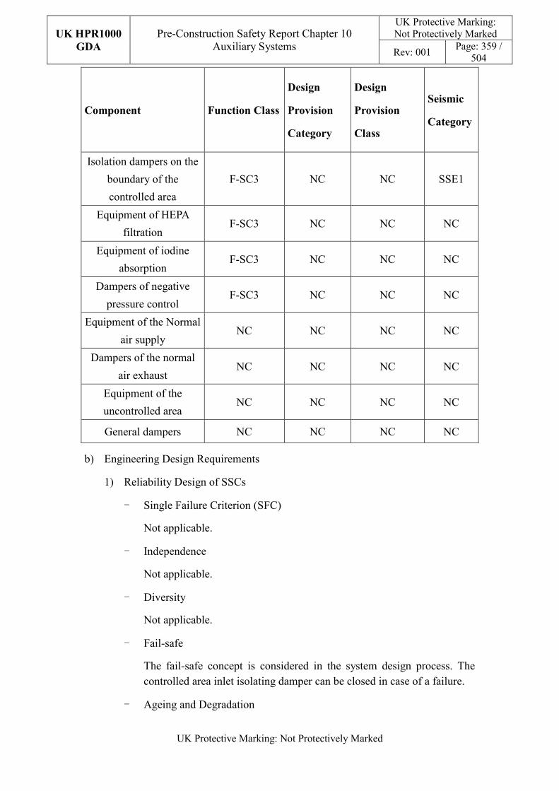
UK HPR1000
GDA
Pre-Construction Safety Report Chapter 10 Auxiliary Systems
UK Protective Marking: Not Protectively Marked
Rev: 001 Page: 359 /
504
UK Protective Marking: Not Protectively Marked
Component Function Class
Design
Provision
Category
Design
Provision
Class
Seismic
Category
Isolation dampers on the
boundary of the
controlled area
F-SC3 NC NC SSE1
Equipment of HEPA
filtration F-SC3 NC NC NC
Equipment of iodine
absorption F-SC3 NC NC NC
Dampers of negative
pressure control F-SC3 NC NC NC
Equipment of the Normal
air supply NC NC NC NC
Dampers of the normal
air exhaust NC NC NC NC
Equipment of the
uncontrolled area NC NC NC NC
General dampers NC NC NC NC
b) Engineering Design Requirements
1) Reliability Design of SSCs
- Single Failure Criterion (SFC)
Not applicable.
- Independence
Not applicable.
- Diversity
Not applicable.
- Fail-safe
The fail-safe concept is considered in the system design process. The controlled area inlet isolating damper can be closed in case of a failure.
- Ageing and Degradation
UK HPR1000
GDA
Pre-Construction Safety Report Chapter 10 Auxiliary Systems
UK Protective Marking: Not Protectively Marked
Rev: 001 Page: 360 /
504
UK Protective Marking: Not Protectively Marked
The plant design life is 60 years. Some components to be replaced at the end of their individual design life. All the vulnerable parts can be replaced, as the moving equipment is designed as being available at 2×100%.
The performance of equipment is guaranteed through life examination, inspection, maintenance and testing, as well as the monitoring during normal operation, which can ensure that ageing effects do not compromise safety performance. The detailed design arrangement around EMIT and equipment monitoring is presented in the SDM, Reference [146].
The system layout design in the detailed design stage can ensure the accessibility and requirement for safety equipment in-service inspection and periodic tests including the necessary Non-Destructive Testing (NDT), as well as the requirements of emergency and scheduled maintenance on the SSCs. Detailed layout information is presented in Reference [145].
2) Human Factors
The DWQ [WTBVS] air supply and exhaust fans are arranged in the ventilation equipment rooms which can be easily accessed and equipment can be examined at any time. The DWQ [WTBVS] is controlled and monitored in the main control room which allows for convenient operation.
The system design of the DWQ [WTBVS] does not require short term operator intervention, however there are operator actions during plant normal operation, the effect of which needs to be estimated. Detailed design information about instrumentation and control is presented in the SDM, Reference [146].
3) Autonomy
- Autonomy in Respect of Operators
The design principles relevant to the autonomy in respect of operators are not applicable for DWQ [WTBVS] design.
- Autonomy in Respect of the Heat Sink
The design principles relevant to the autonomy in respect of the heat sink are not applicable for DWQ [WTBVS] design.
- Autonomy in Respect of Power Supply Systems
The design principles relevant to the autonomy in respect of the power supply are not applicable for DWQ [WTBVS] design.
UK HPR1000
GDA
Pre-Construction Safety Report Chapter 10 Auxiliary Systems
UK Protective Marking: Not Protectively Marked
Rev: 001 Page: 361 /
504
UK Protective Marking: Not Protectively Marked
4) Other Design Requirements
- Prevention of Harmful Interactions of Systems Important to Safety
Not applicable.
- Considerations Related to the Electrical Power Grid
The functionality of items important to safety in the DWQ [WTBVS] is not compromised by disturbances in the electrical power grid. Detailed design information of the electrical power grid is presented in the Reference [143].
c) Equipment Qualification
Some components of the DWQ [WTBVS] required performing safety functions are capable of operating under both normal and accident conditions.
All the seismically classified components of the DWQ [WTBVS] shall be capable of operating during and after the SSE. The components are seismically designed and qualified for the SSE loads.
Principles of equipment qualification classification of the system are presented in Reference [147]. Detailed information related to the system equipment qualification is presented in Reference [143].
d) Protection Design against Internal and External Hazards
The HVAC systems comply with the requirements of external and internal hazards stated in Sub-chapter 10.2.4, for ventilation system, the corresponding protection measures of earthquake and internal fire are described as below.
1) External hazards
- Earthquake
The supply air isolation dampers on the air intake and non-return valves installed on the boundary of controlled area and uncontrolled area are designed to withstand an earthquake (classified SSE1).
2) Internal hazards
- Internal Fire
The fire rating of the duct is same as the fire barrier when it passes through the barrier, if not, fire dampers are equipped in the duct. The fire rating of the duct is achieved by fireproof wrap.
Specific protection measures of other hazards are presented in Reference [145].
e) Commissioning
UK HPR1000
GDA
Pre-Construction Safety Report Chapter 10 Auxiliary Systems
UK Protective Marking: Not Protectively Marked
Rev: 001 Page: 362 /
504
UK Protective Marking: Not Protectively Marked
Commissioning and tests shall be carried out to validate the system’s functionality. The methodology of system commissioning programme design is presented in Reference [31]. Further detailed site specific arrangements for the UK HPR1000 commissioning activities will be presented during the nuclear site licencing phase in conjunction with the site licensee.
f) Examination, Inspection, Maintenance and Testing
1) Examination and Inspection
The combined information of the DWQ [WTBVS] displayed in the Main Control Room (MCR) for the operator includes:
- Differential pressure between the BWX and the outside;
- Differential pressure between the supply fans outlet and the outside;
- Differential pressure between the exhaust air lines and the outside;
- Differential pressure between all the fans inlet and the outlet;
- Temperature of the supply air;
- Temperature of the monitoring room;
- Temperature of the electric heaters in the iodine train;
- Position of the isolated dampers;
- Position of the volume control dampers;
- Position of fire dampers;
- Status of fans;
- Status of the electric heaters.
2) Maintenances
Supply fans, exhaust fans and iodine fans have standby maintenance which can be completed while the DWQ [WTBVS] is in operation.
The maintenance of exhaust filtration trains including the iodine adsorption train can be performed at any time when there’s a maintenance line available.
Component maintenance should be done during system shutdown.
3) Periodic Tests
For the UK HPR1000, the periodic test design method is presented in the Reference [32]. FC3 equipment should be tested if they are not in continuous operation.
UK HPR1000
GDA
Pre-Construction Safety Report Chapter 10 Auxiliary Systems
UK Protective Marking: Not Protectively Marked
Rev: 001 Page: 363 /
504
UK Protective Marking: Not Protectively Marked
The controlled area inlet isolating damper should be tested periodically.
Efficiency of the Iodine adsorber and HEPA should be tested periodically.
Detailed design around EMIT is presented in the SDM, Reference [146].
g) Decommissioning
Decommissioning considerations are taken into account of system design. The principles are given in SDM chapter 3, Reference [147].
h) Material Selection
The main supply and exhausts of the ducts are made of concrete.
Ducts for supply air distribution and exhaust air collection are folded and made of galvanised sheet metal.
Airtight exhaust air ducts are made of welded carbon steel with a painted surface.
10.6.16.6 Simplified Diagrams
The simplified system diagram is presented in Figure F-10.6-14; the detailed system functional diagrams are presented in Reference [148].
10.6.17 Safety Chilled Water System (DEL [SCWS])
The DEL [SCWS] provides chilled water to safety-classified ventilation systems and the RIS [SIS] Low Head Safety Injection (LHSI) pumps in trains A and B. Information of the system is presented in the SDM chapter 2, Reference [150].
10.6.17.1 Safety Functional Requirements
10.6.17.1.1 Control of Reactivity
The DEL [SCWS] does not contribute to this safety function.
10.6.17.1.2 Removal of Heat
The DEL [SCWS] does not contribute to this safety function.
10.6.17.1.3 Confinement
With respect to its contribution to confinement, the DEL [SCWS] must satisfy the following requirement:
Environmental protection: The DEL [SCWS] pipes and equipment connected with the RRI [CCWS] must prevent minor radioactive release following a mechanical failure.
10.6.17.1.4 Extra Safety Functions
With respect to its contribution to the extra safety functions, the DEL [SCWS] must satisfy the following requirements:
UK HPR1000
GDA
Pre-Construction Safety Report Chapter 10 Auxiliary Systems
UK Protective Marking: Not Protectively Marked
Rev: 001 Page: 364 /
504
UK Protective Marking: Not Protectively Marked
a) Supporting the Fundamental Safety Functions
The DEL [SCWS] must provide chilled water to safety classified cooling coils or cooling units for the following ventilation systems: the DVL [EDSBVS], DWL [SBCAVS], DCL [MCRACS] and DWK [FBVS].
In case of a failure of normal cooling the RIS [SIS] LHSI pumps of trains A and B (normally provided by the RRI [CCWS]) the DEL [SCWS] must provide emergency chilled water to these pumps instead.
b) Prevent, Protect and Mitigate Hazards Impact
External explosion: The DEL [SCWS] must prevent external explosions from affecting the operation of the air-cooled chiller units.
10.6.17.2 Design Requirements
The general design requirements of the HVAC systems which need to be considered are shown in Sub-chapter 10.2.4, among which the following requirements are not applicable for the DEL [SCWS]:
a) Autonomy in Respect of Heat Sink
Not applicable, because the DEL [SCWS] doesn’t provide a heat sink to the power plant.
b) Prevention of Harmful Interactions of Systems Important to Safety
Not applicable, because the DEL [SCWS] doesn’t have harmful interactions of systems important to safety.
The substantiation analysis of the DEL [SCWS] to other design requirements is shown in the Sub-chapter 10.6.17.5.2.
10.6.17.3 Design Bases
10.6.17.3.1 General Assumptions
The external conditions to be taken into account for the DEL [SCWS] are defined in Table T-10.6-41.
10.6.17.3.2 Design Assumptions
a) Control of Reactivity
Not applicable. The DEL [SCWS] does not contribute to the safety function of control of reactivity.
b) Removal of Heat
Not applicable. The DEL [SCWS] does not contribute to the safety function of removal of heat.
UK HPR1000
GDA
Pre-Construction Safety Report Chapter 10 Auxiliary Systems
UK Protective Marking: Not Protectively Marked
Rev: 001 Page: 365 /
504
UK Protective Marking: Not Protectively Marked
c) Confinement
Not applicable. There’s no quantitative safety-related design assumption for the DEL [SCWS].
d) Extra Safety Functions
1) Supporting the Fundamental Safety Functions
The temperature of supply chilled water is 7°C and the temperature of return water is 12°C.
The capacity of the chiller unit is determined by the maximum sum of the loads of all consumers under each condition.
2) Prevent, Protect and Mitigate Hazards Impact
External explosion: The parameters of external explosions are given in Chapter 18 (External Hazards).
e) Other Assumptions
Not applicable. There’s no quantitative design assumption for the DEL [SCWS].
10.6.17.4 System Description and Operation
10.6.17.4.1 System Description
a) General System Description
The DEL [SCWS] includes trains A, B and C. The three trains are mutually independent and physically separated. The chiller units of trains A and B are air-cooled, train C is water-cooled. Each train provides chilled water for the safety-classified cooling coils or cooling units of the DVL [EDSBVS], DWL [SBCAVS], and DWK [FBVS] in the corresponding buildings and DCL [MCRACS]. Trains A and B can serve as a backup of the RRI [CCWS] to cool the RIS [SIS] LHSI pumps.
Each train consists of:
1) A main circuit supplying chilled water to the consumers, which includes:
- A chiller unit;
- A circulating pump;
- A by-pass line equipped with a motorised control valve, in order to regulate the chilled water flow rate through the evaporator.
2) Connected to the main circuit:
- An expansion tank to absorb the pressure variations in the circuit;
UK HPR1000
GDA
Pre-Construction Safety Report Chapter 10 Auxiliary Systems
UK Protective Marking: Not Protectively Marked
Rev: 001 Page: 366 /
504
UK Protective Marking: Not Protectively Marked
- A safety valve to prevent a possible overpressure in the circuit.
3) Sub-circuits for the chilled water supply of each consumer.
Detailed information of the systems is presented in the SDM, Reference [149].
b) Description of Main Equipment
1) Chiller units
The chilled water distributed to consumers is provided by chiller units. There are three chiller units in the DEL [SCWS]. Trains A and B are air-cooled, while train C is water-cooled. In the three chiller units, R134a is used as the refrigerant.
T-10.6-30 Main Data Sheet of Chiller Units
Chiller DEL [SCWS] train
A B C
Type Air-cooled Air-cooled Water-cooled
Chiller refrigerating capacity (kW) 1320 1320 1150
Coefficient Of Performance 2.4 2.4 5.1
Power (kW) 550 550 320
2) Circulating pumps
The circulating pumps allow the supply of chilled water to the consumers. The three pumps are identical single stage centrifugal pumps.
Detailed information of the equipment design is presented in the SDM chapter 4, Reference [149].
c) Description of Main Layout
The chiller unit and pump of each DEL [SCWS] train are located in corresponding safeguard building.
Detailed design information about the system layout is presented in the SDM, Reference [151].
d) Description of System Interface
The DEL [SCWS] is connected to the following mechanical systems (not including power supplies and I&C systems):
1) SED [DWDS(NI)]
This system is used for main circulating circuit filling and possible make-up.
2) SIH [CDS]
This system is used for injecting chemical reagents non-continuously into the
UK HPR1000
GDA
Pre-Construction Safety Report Chapter 10 Auxiliary Systems
UK Protective Marking: Not Protectively Marked
Rev: 001 Page: 367 /
504
UK Protective Marking: Not Protectively Marked
DEL [SCWS] to absorb oxygen and to prevent the occurrence of corrosion processes.
3) RPE [VDS]
This system is used to collect possible releases from the safety valves in case of exceeding the maximum pressure in the main circulating circuit. It is also used to collect the drains of the lines to the RPE [VDS] floor drain.
4) RRI [CCWS]
In train C, this system is used to cool the chiller unit condenser water providing a heat sink to the chiller unit.
Moreover, the DEL [SCWS] system provides chilled water to the DCL [MCRACS], DVL [EDSBVS], DWL [SBCAVS], DWK [FBVS] and RIS [SIS].
Detailed information of the interface systems is presented in the SDM, Reference [149].
e) Description of Instrumentation and Control
Instruments controlling and monitoring the DEL [SCWS] and displaying of the actuator are provided in the MCR.
Detailed information of the system I&C design is presented in the SDM, Reference [152].
10.6.17.4.2 System Operation
a) Plant Normal Conditions
The three trains of the DEL [SCWS] shall run permanently in plant normal conditions.
b) Plant Accident Conditions
Under plant accident conditions, the three trains of the DEL [SCWS] operate continuously and the supplied refrigeration capacity depends on the need of the ventilation system.
Train C which is cooled by the RRI [CCWS] is lost following a loss of the ultimate heat sink. Trains A and B which are cooled by outdoor air are affected.
In case of LOOP, each train is powered by a corresponding emergency diesel generator.
In case of SBO, the equipment of the trains A and B is powered by their corresponding SBO diesel generator. Train C is not operational.
UK HPR1000
GDA
Pre-Construction Safety Report Chapter 10 Auxiliary Systems
UK Protective Marking: Not Protectively Marked
Rev: 001 Page: 368 /
504
UK Protective Marking: Not Protectively Marked
Detailed information of the system operation is presented in the SDM, Reference [152].
10.6.17.5 Preliminary Design Substantiation
In this sub-chapter, the system design is demonstrated to satisfy the safety functional requirements presented in Sub-chapter 10.6.17.1 and the general design requirements stated in Sub-chapter 10.2.4. Review of the consistency of the system design against the newly developed principles is currently being undertaken.
10.6.17.5.1 Compliance with Safety Functional Requirements
a) Control of Reactivity
Not applicable.
b) Removal of Heat
Not applicable.
c) Confinement
1) Environmental Protection
The DEL [SCWS] components which contribute to prevent minor radioactive release are designed to meet sufficient mechanical requirements.
d) Extra Safety Functions
1) Supporting the Fundamental Safety Functions
The DEL [SCWS] components are sized to meet the cooling requirements of its served HVAC systems (DVL [EDSBVS], DCL [MCRACS], DWL [SBCAVS] and DWK [FBVS]) under all summer and winter conditions as defined in Table T-10.6-41.
The DEL [SCWS] components are sized to meet the cooling requirements of the RIS [SIS] LHSI pump motors in the case of Total Loss of Cooling Chain (TLOCC) and SBO events.
2) Prevent, Protect and Mitigate Hazards Impact
- External explosion
The DEL [SCWS] air-cooled chiller units are designed to endure the external explosion loads.
Detailed design information is presented in Reference [153].
10.6.17.5.2 Compliance with Design Requirements
a) Safety Classification
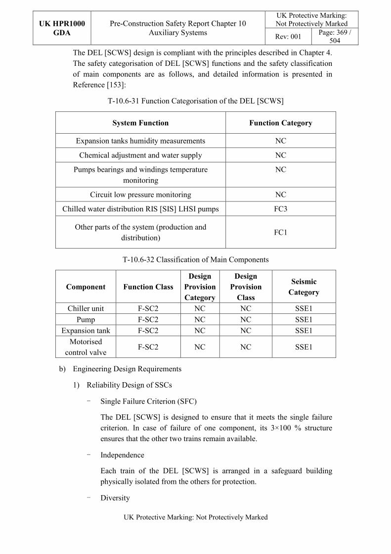
UK HPR1000
GDA
Pre-Construction Safety Report Chapter 10 Auxiliary Systems
UK Protective Marking: Not Protectively Marked
Rev: 001 Page: 369 /
504
UK Protective Marking: Not Protectively Marked
The DEL [SCWS] design is compliant with the principles described in Chapter 4. The safety categorisation of DEL [SCWS] functions and the safety classification of main components are as follows, and detailed information is presented in Reference [153]:
T-10.6-31 Function Categorisation of the DEL [SCWS]
System Function Function Category
Expansion tanks humidity measurements NC
Chemical adjustment and water supply NC
Pumps bearings and windings temperature monitoring
NC
Circuit low pressure monitoring NC
Chilled water distribution RIS [SIS] LHSI pumps FC3
Other parts of the system (production and distribution)
FC1
T-10.6-32 Classification of Main Components
Component Function Class
Design
Provision
Category
Design
Provision
Class
Seismic
Category
Chiller unit F-SC2 NC NC SSE1
Pump F-SC2 NC NC SSE1
Expansion tank F-SC2 NC NC SSE1
Motorised control valve
F-SC2 NC NC SSE1
b) Engineering Design Requirements
1) Reliability Design of SSCs
- Single Failure Criterion (SFC)
The DEL [SCWS] is designed to ensure that it meets the single failure criterion. In case of failure of one component, its 3×100 % structure ensures that the other two trains remain available.
- Independence
Each train of the DEL [SCWS] is arranged in a safeguard building physically isolated from the others for protection.
- Diversity
UK HPR1000
GDA
Pre-Construction Safety Report Chapter 10 Auxiliary Systems
UK Protective Marking: Not Protectively Marked
Rev: 001 Page: 370 /
504
UK Protective Marking: Not Protectively Marked
The DEL [SCWS] heat sink diversification is provided by the choice of the condenser type of the chiller units: trains A and B are air-cooled, train C is RRI [CCWS] water-cooled.
The weakness of HVAC diversity design will be identified in Justification of the diversification of HVAC systems report. And a preliminary design of the diverse HVAC systems will be provided. Detailed diversity modification of HVAC systems will be finished in step 4.
- Fail-safe
The fail-safe concept is considered in the system design process.
After comprehensive analysis, other measures such as redundancy are used to improve safety in order to avoid the potential safety risks that may be introduced by “fail-safe” design on power plant.
- Ageing and Degradation
The plant design life is 60 years. Some components to be replaced at the end of their individual design life. For the chiller unit design, vibration ageing and radiation ageing are taken into consideration. The capacity of the chiller unit is monitored and recorded in real time, which is convenient for the operator to assess the performance of the chiller unit.
2) Human Factors
The system design of the DEL [SCWS] does not require short term operator intervention, however there are operator actions during plant normal operation, the effect of which needs to be estimated. The chiller unit and pump of each DEL [SCWS] train are located in adjacent equipment rooms, where the equipment layout facilitates their maintenance. The DEL [SCWS] is controlled and monitored in the main control room. It is designed to be convenient for the operator to control.
3) Autonomy
- Autonomy in Respect of Operators
The design principles relevant to the autonomy in respect of operators are detailed in Sub-chapter 10.2.4. The design of the DEL [SCWS] fulfils these principles via control functional design; detailed information is presented in the SDM, Reference [152]. The design result is estimated in the safety analysis.
- Autonomy in Respect of the Heat Sink
The design principles relevant to the autonomy in respect of the heat sink
UK HPR1000
GDA
Pre-Construction Safety Report Chapter 10 Auxiliary Systems
UK Protective Marking: Not Protectively Marked
Rev: 001 Page: 371 /
504
UK Protective Marking: Not Protectively Marked
are not applicable for DEL [SCWS] design.
- Autonomy in Respect of Power Supply Systems
The safety HVAC systems and DEL [SCWS] are required to ensure the operational conditions for the equipment of power supply systems.
4) Other Design Requirements
- Prevention of Harmful Interactions of Systems Important to Safety
Not applicable.
- Considerations Related to the Electrical Power Grid
The pump and chiller design has considered the impact of variations in the voltage and frequency. The functionality of pump and chiller in the DEL [SCWS] is not compromised by disturbances in the electrical power grid. Detailed design information of the electrical power grid is presented in Reference [149].
c) Equipment Qualification
All the components of the DEL [SCWS] required performing safety functions are capable of operating under both normal and accident conditions. As a result, the components can withstand the most adverse environmental conditions expected.
All the seismically classified components of the DEL [SCWS] shall be capable of operating during and after the SSE. The components are seismically designed and qualified for the SSE loads.
Principles of equipment qualification classification of the system are presented in Reference [153]. Detailed information related to the system equipment qualification is presented in Reference [149].
d) Protection against Internal and External Hazards
The HVAC systems comply with the requirements of external and internal hazards stated in Sub-chapter 10.2.4, for ventilation system, the corresponding protection measures of earthquake and internal fire are described as below.
1) External hazards
- Earthquake
The seismic category for the components of the DEL [SCWS] performing Safety Category 1 (FC1) and Safety Category 2 (FC2) is Seismic Category 1 (SSE1).
2) Internal hazards
UK HPR1000
GDA
Pre-Construction Safety Report Chapter 10 Auxiliary Systems
UK Protective Marking: Not Protectively Marked
Rev: 001 Page: 372 /
504
UK Protective Marking: Not Protectively Marked
- Internal Fire
There is no special measure for DEL [SCWS] on internal fire.
Specific protection measures of other hazards are presented in Reference [151].
e) Commissioning
Commissioning and tests shall be carried out to validate the system’s functionality. The methodology of system commissioning programme design is presented in Reference [31]. Further detailed site specific arrangements for the UK HPR1000 commissioning activities will be presented during the nuclear site licencing phase in conjunction with the site licensee.
f) Examination, Inspection, Maintenance and Testing
1) Examination and Inspection
The combined information of the DEL [SCWS] displayed in the Main Control Room (MCR) for the operator includes:
- Differential pressure of the evaporator of the chiller;
- Temperature of the chilled water of the chiller outlet;
- The flow rate of cooling water of the RRI [CCWS].
2) Maintenances
During normal operating conditions, the DEL [SCWS] should supply chilled water to consumers continuously. Maintenance of the components of each train can be carried out when the corresponding train consumers are in maintenance during shutdown of the plant.
3) Periodic Tests
For the UK HPR1000, the periodic test design method is presented in the Reference [32].
FC1, FC2 and FC3 equipment should be tested if they are not in continuous operation. Some equipment performing safety functions shall be subject to periodic testing, mainly including the normal operation point verification pump curve (flow rate/total delivery head) compared to the minimum safety required pump curve.
g) Decommissioning
The design of the DEL [SCWS] considers the decommissioning. A certain gradient is set in the pipeline layout to prevent liquid accumulation and all equipment and pipes can be drained by draining lines. The principles are given in SDM chapter 3, Reference [153].
UK HPR1000
GDA
Pre-Construction Safety Report Chapter 10 Auxiliary Systems
UK Protective Marking: Not Protectively Marked
Rev: 001 Page: 373 /
504
UK Protective Marking: Not Protectively Marked
h) Material Selection
Equipment in contact with outside air is protected against corrosion due to the saline atmosphere through a paint coating.
The entire DEL [SCWS] equipment is made of carbon steel.
The insulation material of the chilled water pipe is made of glass fibre.
10.6.17.6 Simplified Diagrams
The simplified system diagram is presented in Figure F-10.6-15; the detailed system functional diagrams are presented in Reference [154].
10.6.18 Operational Chilled Water System (DER [OCWS])
The DER [OCWS] provides chilled water to non-classified ventilation systems and other non-classified users.
10.6.18.1 Safety Functional Requirements
10.6.18.1.1 Control of Reactivity
The DER [OCWS] does not contribute to this safety function.
10.6.18.1.2 Removal of Heat
The DER [OCWS] does not contribute to this safety function.
10.6.18.1.3 Confinement
With respect to its contribution to confinement, the DER [OCWS] must satisfy the following requirement:
a) Environmental Protection
The DER [OCWS] pipes and equipment connected with the RRI [CCWS] must prevent minor radioactive release following a mechanical failure.
b) Third containment barrier
Under accident conditions, the DER [OCWS] must enable isolation of the containment at its containment penetration points. For details see Chapter 7 (Sub-chapter 7.4.6 Containment Isolation).
10.6.18.1.4 Extra Safety Functions
The DER [OCWS] does not contribute to these functions.
10.6.18.2 Design Requirements
The general design requirements of the HVAC systems which need to be considered are shown in Sub-chapter 10.2.4, among which the following requirements are not
UK HPR1000
GDA
Pre-Construction Safety Report Chapter 10 Auxiliary Systems
UK Protective Marking: Not Protectively Marked
Rev: 001 Page: 374 /
504
UK Protective Marking: Not Protectively Marked
applicable for the DER [OCWS]:
a) Autonomy in Respect of Operators
Not applicable, because the DER [OCWS] doesn’t contribute to the autonomy objective.
b) Autonomy in Respect of the Heat Sink
Not applicable, because the DER [OCWS] doesn’t provide a heat sink to the power plant.
c) Autonomy in Respect of Power Supply Systems
Not applicable, because the DER [OCWS] doesn’t provide a power supply to the power plant.
d) Prevention of Harmful Interactions of Systems Important to Safety
Not applicable, because the DER [OCWS] doesn’t have harmful interactions of systems important to safety.
The substantiation analysis of the DER [OCWS] to other design requirements is shown in the Sub-chapter 10.6.18.5.2.
10.6.18.3 Design Bases
10.6.18.3.1 General Assumptions
Not applicable.
10.6.18.3.2 Design Assumptions
a) Control of Reactivity
Not applicable. The DER [OCWS] does not contribute to the safety function of control of reactivity.
b) Removal of Heat
Not applicable. The DER [OCWS] does not contribute to the safety function of removal of heat.
c) Confinement
Not applicable. There’s no quantitative safety-related design assumption for the DER [OCWS].
d) Extra Safety Functions
Not applicable. The DER [OCWS] does not contribute to these functions.
e) Other Assumptions
UK HPR1000
GDA
Pre-Construction Safety Report Chapter 10 Auxiliary Systems
UK Protective Marking: Not Protectively Marked
Rev: 001 Page: 375 /
504
UK Protective Marking: Not Protectively Marked
Production and distribution of chilled water of DER [OCWS] subsystem A consists of 4×33% capacity. Production and distribution of chilled water of DER [OCWS] subsystem B consists of 2×100% capacity.
The temperature of supply chilled water is 7°C and the temperature of return water is 12°C.
10.6.18.4 System Description and Operation
10.6.18.4.1 System Description
a) General System Description
The DER [OCWS] includes two subsystems, subsystem A and subsystem B.
1) DER [OCWS] subsystem A
Subsystem A of the DER [OCWS] consists of:
A main circuit supplying chilled water to the consumers (including four RRI [CCWS] water-cooled chiller units in parallel, four circulating pumps and a bypass line equipped with a motorised control valve);
It is connected to the main circuit (including two expansion tanks to maintain a suitable pressure in the circuit and a safety valve to prevent a possible overpressure in the circuit);
Sub-circuits for the chilled water supply of each consumer.
2) DER [OCWS] subsystem B
Subsystem B of the DER [OCWS] consists of:
A main circuit supplying chilled water to the consumers (including two RRI [CCWS] water-cooled chiller units in parallel, two circulating pumps and a bypass line equipped with a motorised control valve);
It is connected to the main circuit (including an expansion tank to maintain a suitable pressure in the circuit and a safety valve to prevent a possible overpressure in the circuit);
Sub-circuits for the chilled water supply of each consumer.
b) Description of Main Equipment
1) Chiller units
The chilled water distributed to consumers is provided by chiller units. There are six water-cooled chiller units in the DER [OCWS]. In these chiller units R134a is used as the refrigerant.
2) Circulating pumps
UK HPR1000
GDA
Pre-Construction Safety Report Chapter 10 Auxiliary Systems
UK Protective Marking: Not Protectively Marked
Rev: 001 Page: 376 /
504
UK Protective Marking: Not Protectively Marked
The circulating pumps allow the supply of chilled water to the consumers. The pumps are single stage centrifugal pumps.
c) Description of Main Layout
The chiller units and pumps of the DER [OCWS] are located in the nuclear auxiliary building.
d) Description of System Interface
The DER [OCWS] is connected to the following mechanical systems (not including power supplies and I&C systems):
1) SED [DWDS(NI)]
This system is used for main circulating circuit filling and possible make-up.
2) SIH [CDS]
This system is used for injecting chemical reagents discontinuously into the DER [OCWS] to absorb oxygen and to prevent the occurrence of corrosion.
3) RPE [VDS]
This system is used to collect possible releases from the safety valves in case of exceeding the maximum pressure in the main circulating circuit. It is also used to collect the drains of the lines to the RPE [VDS] floor drain.
4) RRI [CCWS]
This system is used to cool the chiller unit condenser, providing a heat sink to the chiller unit.
Moreover, the DER [OCWS] provides chilled water to non-classified consumers, such as: DWN [NABVS], DVL [EDSBVS], EVR [CCVS], DWQ [WTBVS], etc.
e) Description of Instrumentation and Control
Instruments controlling and monitoring the DER [OCWS] and displaying of the actuator are provided in the MCR.
10.6.18.4.2 System Operation
a) Plant Normal Conditions
The two DER [OCWS] subsystems run permanently in plant normal conditions.
b) Plant Accident Conditions
1) Loss Of Offsite Power (LOOP)
If subsystem A of the DER [OCWS] fails, subsystem B of the DER [OCWS]
UK HPR1000
GDA
Pre-Construction Safety Report Chapter 10 Auxiliary Systems
UK Protective Marking: Not Protectively Marked
Rev: 001 Page: 377 /
504
UK Protective Marking: Not Protectively Marked
is supplied by the emergency diesel generators when a loss of power outside the plant occurs.
2) Station Black Out (SBO)
The DER [OCWS] is lost in case of a SBO.
3) Loss of Ultimate Heat Sink (LUHS)
The DER [OCWS] is lost in case of a LUHS, due to the loss of the condensers cooling water of the RRI [CCWS].
10.6.18.5 Preliminary Design Substantiation
In this sub-chapter, the system design is demonstrated to satisfy the safety functional requirements presented in Sub-chapter 10.6.18.1 and the general design requirements stated in Sub-chapter 10.2.4. Review of the consistency of the system design against the principles is currently being undertaken.
10.6.18.5.1 Compliance with Safety Functional Requirements
a) Control of Reactivity
Not applicable.
b) Removal of Heat
Not applicable.
c) Confinement
1) Environmental Protection
The DER [OCWS] components which contribute to prevent minor radioactive release are designed to meet sufficient mechanical requirements.
2) Third containment barrier
The inlet penetration is fitted with a containment motorised isolation valve and a check valve. The outlet penetration is fitted with two containment motorised isolation valves. The three containment motorised isolation valves close once receiving a phase 1 containment isolation signal under accident conditions.
d) Extra Safety Functions
Not applicable.
10.6.18.5.2 Compliance with Design Requirements
a) Safety Classification
The DER [OCWS] design is compliant with the principles described in Chapter 4.
UK HPR1000
GDA
Pre-Construction Safety Report Chapter 10 Auxiliary Systems
UK Protective Marking: Not Protectively Marked
Rev: 001 Page: 378 /
504
UK Protective Marking: Not Protectively Marked
The safety categorisation of DER [OCWS] functions and the safety classification of main components are as follows:
T-10.6-33 Function Categorisation of the DER [OCWS]
System Function Function Category
Containment isolation FC1
Cooling by the RRI [CCWS] FC3
Other functions of the system NC
T-10.6-34 Classification of Main Components
Component Function Class
Design
Provision
Category
Design
Provision
Class
Seismic
Category
Containment penetrations
F-SC1 DPM B-SC2 SSE1
Containment isolation valves
F-SC1 DPM B-SC2 SSE1
Chiller unit NC NC NC NC
Pump NC NC NC NC
Expansion tank NC NC NC NC
Motorised control valve
NC NC NC NC
b) Engineering Design Requirements
1) Reliability Design of SSCs
- Single Failure Criterion (SFC)
Subsystem B of the DER [OCWS] containment isolation valves and containment penetrations are designed to ensure they meet the single failure criterion. The 2×100% isolation devices are redundant. The containment isolation valves are powered by diversified electrical switchboards.
- Independence
The two isolation devices of the inlet or outlet penetration line of the DER [OCWS] are physically separated, one on the inside of the reactor building, the other on the outside, in a connecting building.
- Diversity
The containment isolation valves design in the system is compliant with
UK HPR1000
GDA
Pre-Construction Safety Report Chapter 10 Auxiliary Systems
UK Protective Marking: Not Protectively Marked
Rev: 001 Page: 379 /
504
UK Protective Marking: Not Protectively Marked
the diversity principles. The internal containment isolation valves and the external containment isolation valves installed at the return line are designed and provided by different manufacturers; at the supply line, the internal containment isolation valve is designed as a check valve, while the external containment isolation valve is designed as a shut-off valve.
- Fail-safe
The fail-safe concept is considered in the system design process.
After comprehensive analysis, other measures such as redundancy are used to improve safety in order to avoid the potential safety risks that may be introduced by “fail-safe” design on power plant.
- Ageing and Degradation
The plant design life is 60 years. Some components to be replaced at the end of their individual design life. For the chiller unit design, vibration ageing and radiation ageing are taken into consideration.
2) Human Factors
The system design of the DER [OCWS] does not require short term operator intervention, however there are operator actions during plant normal operation, the effect of which needs to be estimated. The chiller unit and pump of each DER [OCWS] train are located in adjacent equipment rooms, where the equipment layout facilitates their maintenance. The DER [OCWS] is controlled and monitored in the main control room. It is designed to be convenient for the operator to control.
3) Autonomy
Not applicable.
4) Other Design Requirements
- Prevention of Harmful Interactions of Systems Important to Safety
Not applicable.
- Considerations Related to the Electrical Power Grid
The functionality of items important to safety in the DER [OCWS] is not compromised by disturbances in the electrical power grid.
c) Equipment Qualification
All the components of the DER [OCWS] required performing safety functions are capable of operating under both normal and accident conditions. As a result, the components can withstand the most adverse environmental conditions expected.
UK HPR1000
GDA
Pre-Construction Safety Report Chapter 10 Auxiliary Systems
UK Protective Marking: Not Protectively Marked
Rev: 001 Page: 380 /
504
UK Protective Marking: Not Protectively Marked
All the seismically classified components of the DER [OCWS] shall be capable of operating during and after the SSE. The components are seismically designed and qualified for the SSE loads.
d) Protection Design against Internal and External Hazards
The HVAC systems comply with the requirements of external and internal hazards stated in Sub-chapter 10.2.4, the corresponding protection measures of earthquake and internal fire are described as below.
1) External hazards
- Earthquake
The seismic category for containment isolation valves of DER [OCWS] performing Safety Category 1 (FC1) is Seismic Category 1 (SSE1).
2) Internal hazards
- Internal Fire
There is no special measure for DER [OCWS] on internal fire.
e) Commissioning
Commissioning shall be carried out for the DER [OCWS] to validate its functionality.
f) Examination, Inspection, Maintenance and Testing
1) Examination and Inspection
The combined information of the DER [OCWS] displayed in the Main Control Room (MCR) for the operator includes:
- Temperature of the chilled water of the chiller outlet;
- The flow rate of cooling water of the RRI [CCWS].
2) Maintenance
During normal operating conditions, the DER [OCWS] should supply chilled water to consumers continuously. According to the configuration, maintenance of the standby pumps and chiller units could be done during power operation conditions.
3) Periodic Tests
FC1, FC2 and FC3 equipment should be tested if they are not in continuous operation. Some equipment performing safety functions shall be subject to periodic testing, mainly consisting of the containment isolation valves.
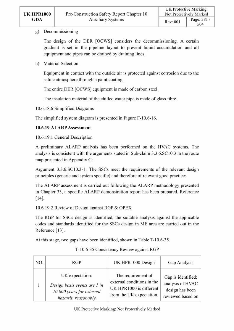
UK HPR1000
GDA
Pre-Construction Safety Report Chapter 10 Auxiliary Systems
UK Protective Marking: Not Protectively Marked
Rev: 001 Page: 381 /
504
UK Protective Marking: Not Protectively Marked
g) Decommissioning
The design of the DER [OCWS] considers the decommissioning. A certain gradient is set in the pipeline layout to prevent liquid accumulation and all equipment and pipes can be drained by draining lines.
h) Material Selection
Equipment in contact with the outside air is protected against corrosion due to the saline atmosphere through a paint coating.
The entire DER [OCWS] equipment is made of carbon steel.
The insulation material of the chilled water pipe is made of glass fibre.
10.6.18.6 Simplified Diagrams
The simplified system diagram is presented in Figure F-10.6-16.
10.6.19 ALARP Assessment
10.6.19.1 General Description
A preliminary ALARP analysis has been performed on the HVAC systems. The analysis is consistent with the arguments stated in Sub-claim 3.3.6.SC10.3 in the route map presented in Appendix C:
Argument 3.3.6.SC10.3-1: The SSCs meet the requirements of the relevant design principles (generic and system specific) and therefore of relevant good practice:
The ALARP assessment is carried out following the ALARP methodology presented in Chapter 33, a specific ALARP demonstration report has been prepared, Reference [14].
10.6.19.2 Review of Design against RGP & OPEX
The RGP for SSCs design is identified, the suitable analysis against the applicable codes and standards identified for the SSCs design in ME area are carried out in the Reference [13].
At this stage, two gaps have been identified, shown in Table T-10.6-35.
T-10.6-35 Consistency Review against RGP
NO. RGP UK HPR1000 Design Gap Analysis
1
UK expectation:
Design basis events are 1 in
10 000 years for external
hazards, reasonably
The requirement of external conditions in the UK HPR1000 is different from the UK expectation.
Gap is identified; analysis of HVAC design has been
reviewed based on
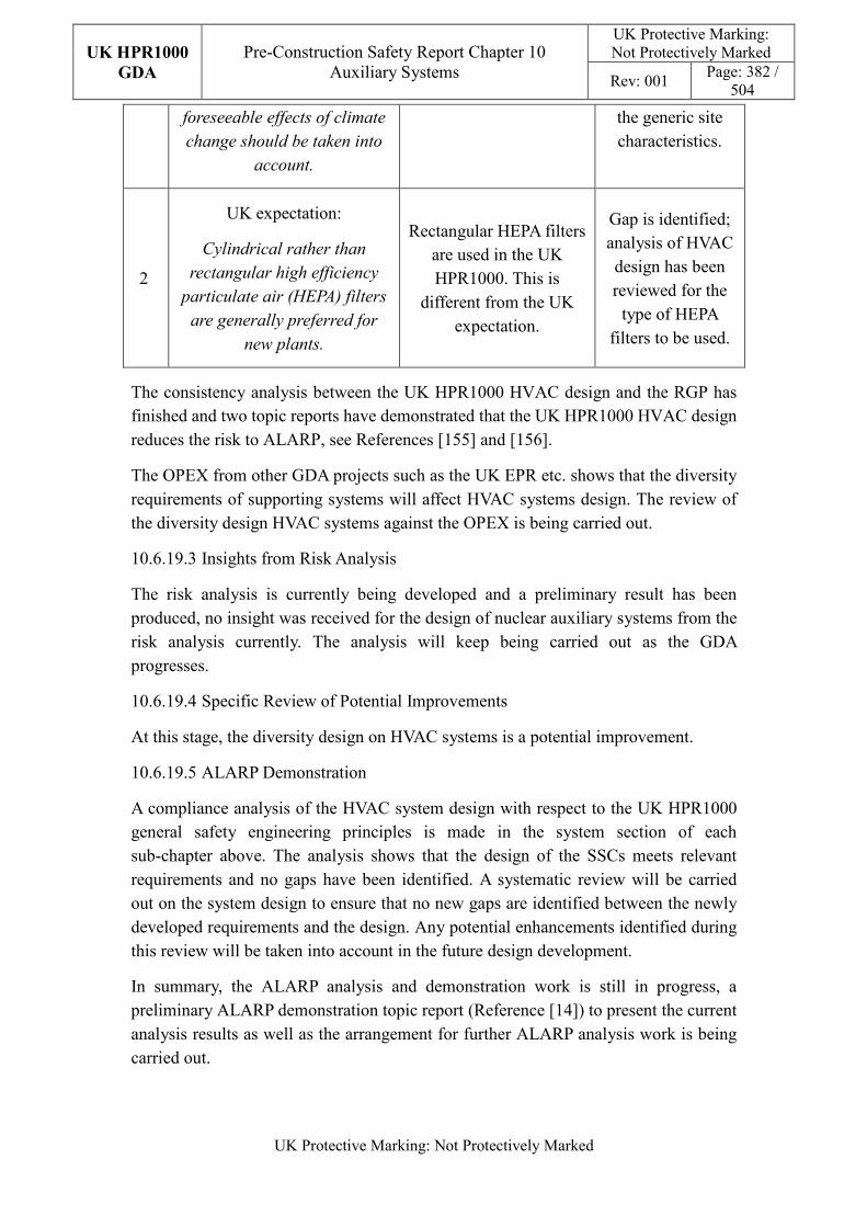
UK HPR1000
GDA
Pre-Construction Safety Report Chapter 10 Auxiliary Systems
UK Protective Marking: Not Protectively Marked
Rev: 001 Page: 382 /
504
UK Protective Marking: Not Protectively Marked
foreseeable effects of climate
change should be taken into
account.
the generic site characteristics.
2
UK expectation:
Cylindrical rather than
rectangular high efficiency
particulate air (HEPA) filters
are generally preferred for
new plants.
Rectangular HEPA filters are used in the UK HPR1000. This is
different from the UK expectation.
Gap is identified; analysis of HVAC design has been reviewed for the
type of HEPA filters to be used.
The consistency analysis between the UK HPR1000 HVAC design and the RGP has finished and two topic reports have demonstrated that the UK HPR1000 HVAC design reduces the risk to ALARP, see References [155] and [156].
The OPEX from other GDA projects such as the UK EPR etc. shows that the diversity requirements of supporting systems will affect HVAC systems design. The review of the diversity design HVAC systems against the OPEX is being carried out.
10.6.19.3 Insights from Risk Analysis
The risk analysis is currently being developed and a preliminary result has been produced, no insight was received for the design of nuclear auxiliary systems from the risk analysis currently. The analysis will keep being carried out as the GDA progresses.
10.6.19.4 Specific Review of Potential Improvements
At this stage, the diversity design on HVAC systems is a potential improvement.
10.6.19.5 ALARP Demonstration
A compliance analysis of the HVAC system design with respect to the UK HPR1000 general safety engineering principles is made in the system section of each sub-chapter above. The analysis shows that the design of the SSCs meets relevant requirements and no gaps have been identified. A systematic review will be carried out on the system design to ensure that no new gaps are identified between the newly developed requirements and the design. Any potential enhancements identified during this review will be taken into account in the future design development.
In summary, the ALARP analysis and demonstration work is still in progress, a preliminary ALARP demonstration topic report (Reference [14]) to present the current analysis results as well as the arrangement for further ALARP analysis work is being carried out.
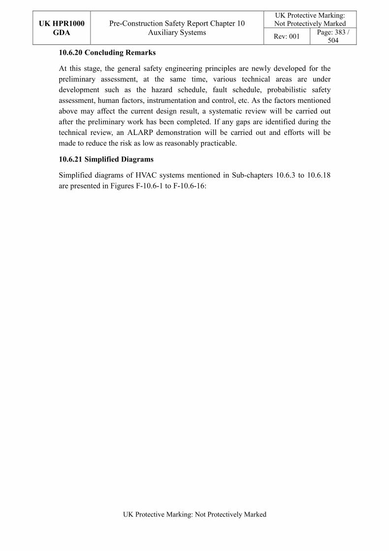
UK HPR1000
GDA
Pre-Construction Safety Report Chapter 10 Auxiliary Systems
UK Protective Marking: Not Protectively Marked
Rev: 001 Page: 383 /
504
UK Protective Marking: Not Protectively Marked
10.6.20 Concluding Remarks
At this stage, the general safety engineering principles are newly developed for the preliminary assessment, at the same time, various technical areas are under development such as the hazard schedule, fault schedule, probabilistic safety assessment, human factors, instrumentation and control, etc. As the factors mentioned above may affect the current design result, a systematic review will be carried out after the preliminary work has been completed. If any gaps are identified during the technical review, an ALARP demonstration will be carried out and efforts will be made to reduce the risk as low as reasonably practicable.
10.6.21 Simplified Diagrams
Simplified diagrams of HVAC systems mentioned in Sub-chapters 10.6.3 to 10.6.18 are presented in Figures F-10.6-1 to F-10.6-16:
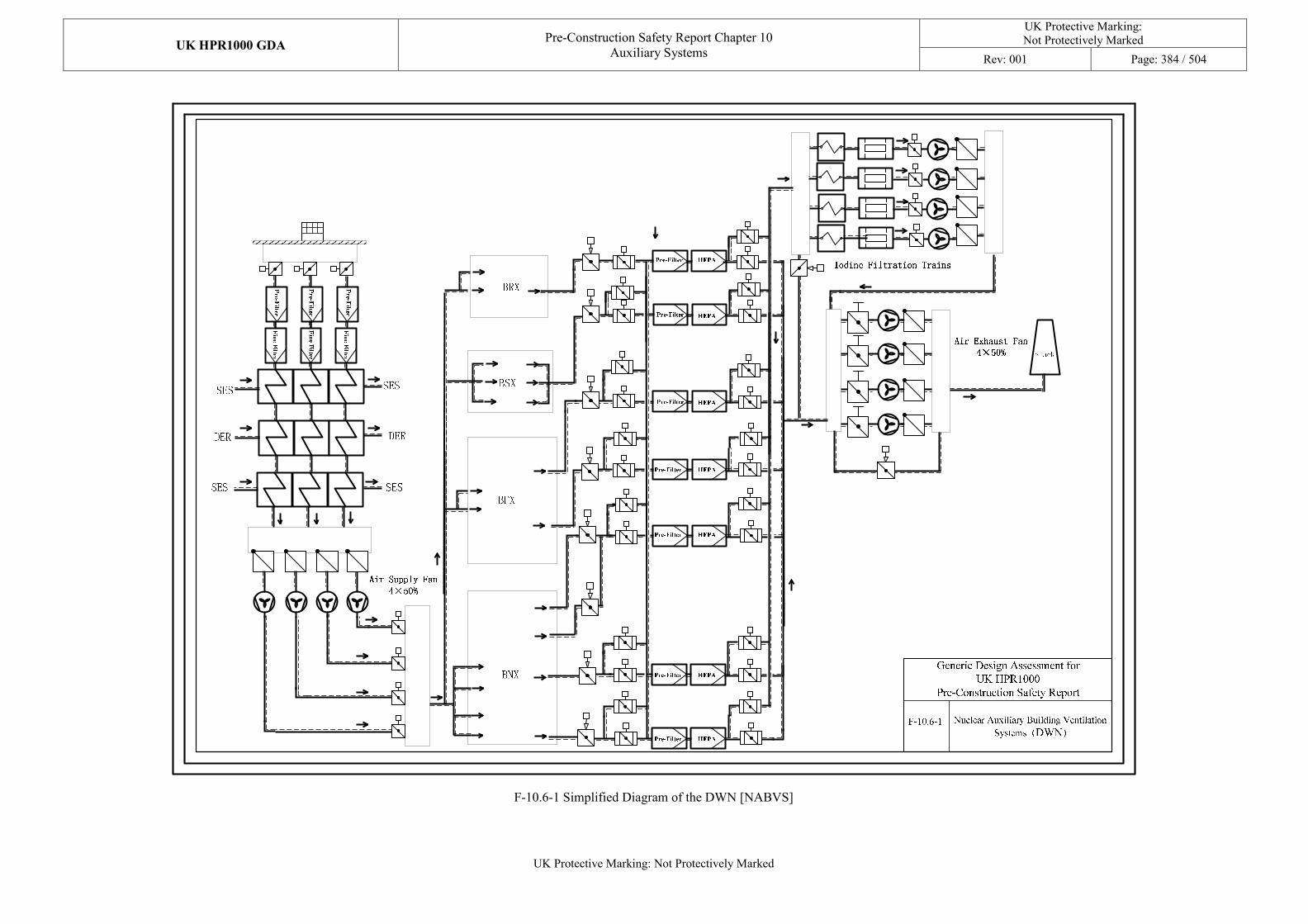
UK HPR1000 GDA Pre-Construction Safety Report Chapter 10
Auxiliary Systems
UK Protective Marking: Not Protectively Marked
Rev: 001 Page: 384 / 504
UK Protective Marking: Not Protectively Marked
F-10.6-1 Simplified Diagram of the DWN [NABVS]
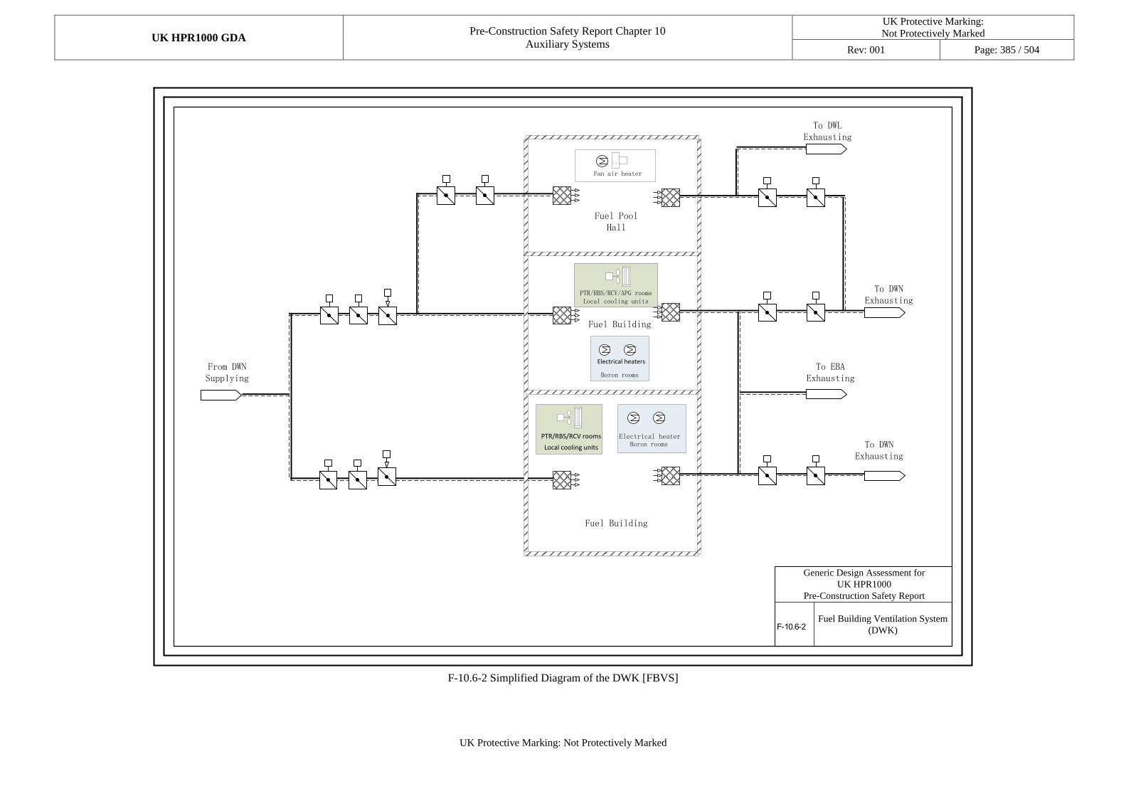
UK HPR1000 GDA Pre-Construction Safety Report Chapter 10
Auxiliary Systems
UK Protective Marking:
Not Protectively Marked
Rev: 001 Page: 385 / 504
UK Protective Marking: Not Protectively Marked
Fuel Building Ventilation System
(DWK)
From DWN Supplying
To DWL Exhausting
To DWN Exhausting
Fuel Building
To DWN Exhausting
To EBA Exhausting
Fuel Building
Fuel Pool Hall
Generic Design Assessment for
UK HPR1000
Pre-Construction Safety Report
F-10.6-2
``
PTR/RBS/RCV/APG rooms Local cooling units
Electrical heaters
Boron rooms
Electrical heaterPTR/RBS/RCV rooms
Local cooling units Boron rooms
Fan air heater
F-10.6-2 Simplified Diagram of the DWK [FBVS]
UK HPR1000 GDA Pre-Construction Safety Report Chapter 10
Auxiliary Systems
UK Protective Marking:
Not Protectively Marked
Rev: 001 Page: 386 / 504
UK Protective Marking: Not Protectively Marked
CRDM area ventilation subsystem
4×50%
To 1
st l
oop
equip
men
t ar
ea
To valves
area
Dome ventilation subsystem
2×100%
Main ventilation subsystem
4×50%
Reactor pit ventilation
subsystem 4×50%
Reactor Building
Dome
To 2
st l
oop
equip
men
t ar
ea
To 3
st l
oop
equip
men
t ar
ea
F-10.6-3Containment Cooling Ventilation
System (EVR)
Fro
m D
ER
To
DE
RF
rom
DE
R
Fro
m D
ER
Fro
m D
ER
To
DE
R
To
DE
R
To
DE
R
Fro
m R
RI
To
RR
I
Fro
m R
RI
To
RR
I
In the event of
SBO
Generic Design Assessment for
UK HPR1000
Pre-Construction Safety Report
Fan
Cooling coil
Cooling coil
Fan
Fan
Fan
F-10.6-3 Simplified Diagram of the EVR [CCVS]
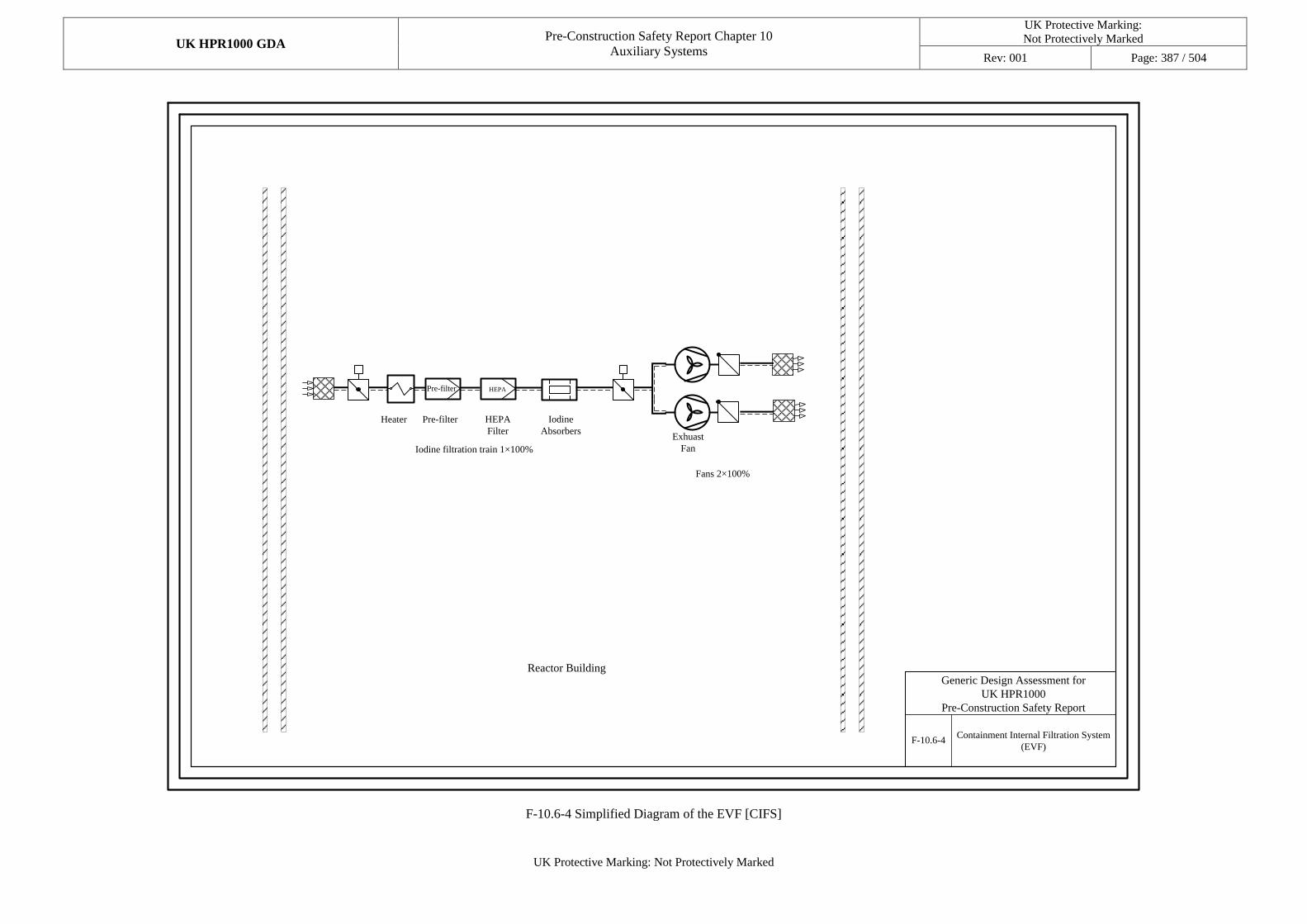
UK HPR1000 GDA Pre-Construction Safety Report Chapter 10
Auxiliary Systems
UK Protective Marking:
Not Protectively Marked
Rev: 001 Page: 387 / 504
UK Protective Marking: Not Protectively Marked
Containment Internal Filtration System
(EVF)
Iodine filtration train 1×100%
Pre-filter HEPA
Fans 2×100%
Reactor BuildingGeneric Design Assessment for
UK HPR1000
Pre-Construction Safety Report
F-10.6-4
Iodine
AbsorbersExhuast
Fan
HEPA
Filter
Pre-filterHeater
F-10.6-4 Simplified Diagram of the EVF [CIFS]
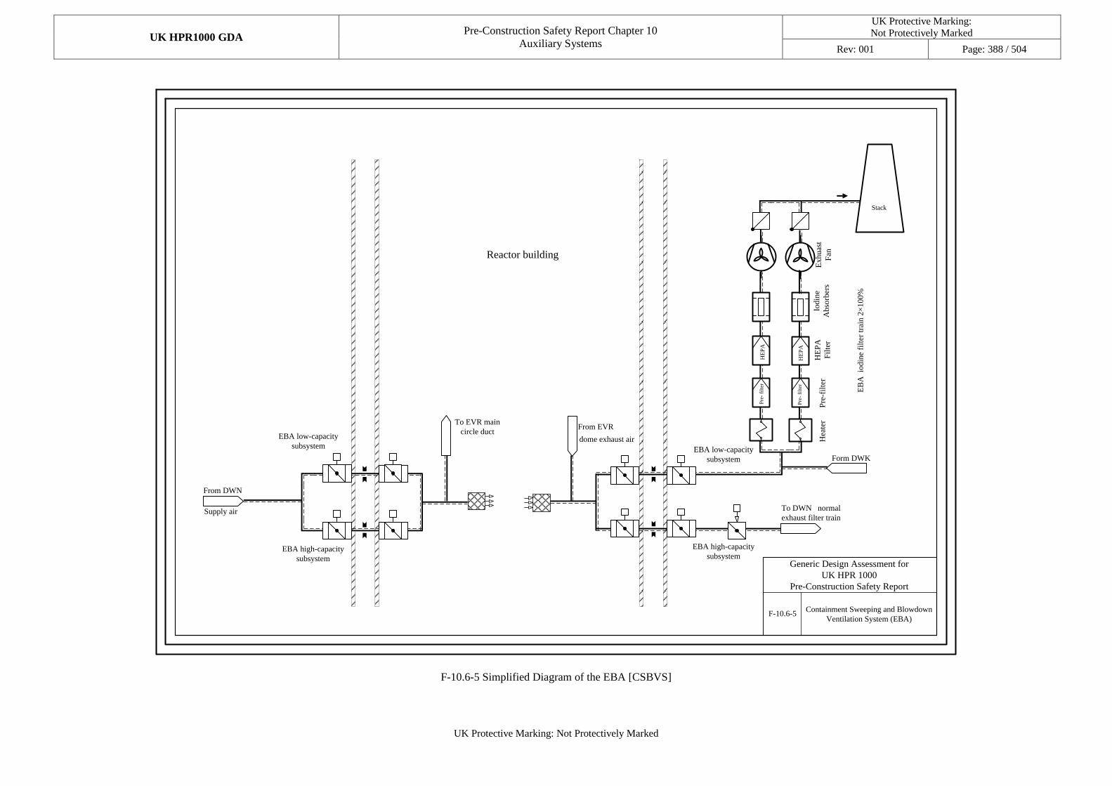
UK HPR1000 GDA Pre-Construction Safety Report Chapter 10
Auxiliary Systems
UK Protective Marking:
Not Protectively Marked
Rev: 001 Page: 388 / 504
UK Protective Marking: Not Protectively Marked
Containment Sweeping and Blowdown
Ventilation System (EBA)
To DWN normal
exhaust filter train
EB
A io
din
e fi
lter
tra
in 2
×100%
HE
PA
Form DWK
From EVRTo EVR main
circle duct
From DWN
Reactor building
Supply air
dome exhaust air
Pre
- fi
lter
EBA low-capacity
subsystem
EBA high-capacity
subsystemGeneric Design Assessment for
UK HPR 1000
Pre-Construction Safety Report
F-10.6-5
Stack
HE
PA
Pre
- fi
lter
EBA low-capacity
subsystem
EBA high-capacity
subsystem
Iodin
e
Abso
rber
sE
xhuas
t
Fan
HE
PA
Fil
ter
Pre
-fil
ter
Hea
ter
F-10.6-5 Simplified Diagram of the EBA [CSBVS]
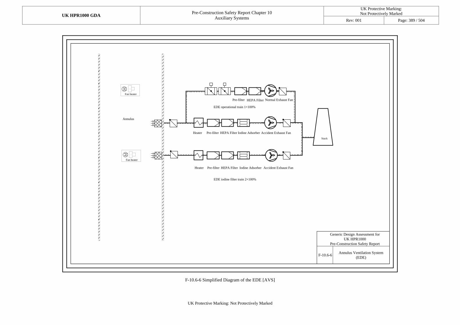
UK HPR1000 GDA Pre-Construction Safety Report Chapter 10
Auxiliary Systems
UK Protective Marking:
Not Protectively Marked
Rev: 001 Page: 389 / 504
UK Protective Marking: Not Protectively Marked
Annulus
F-10.6-6Annulus Ventilation System
(EDE)
EDE iodine filter train 2×100%
Generic Design Assessment for
UK HPR1000
Pre-Construction Safety Report
Stack
EDE operational train 1×100%
Heater
Heater
Pre-filter
Pre-filter
Pre-filter
HEPA Filter
HEPA Filter
HEPA Filter Normal Exhaust Fan
Accident Exhaust Fan
Accident Exhaust Fan
Iodine Adsorber
Iodine Adsorber
``
Fan heater
``
Fan heater
F-10.6-6 Simplified Diagram of the EDE [AVS]
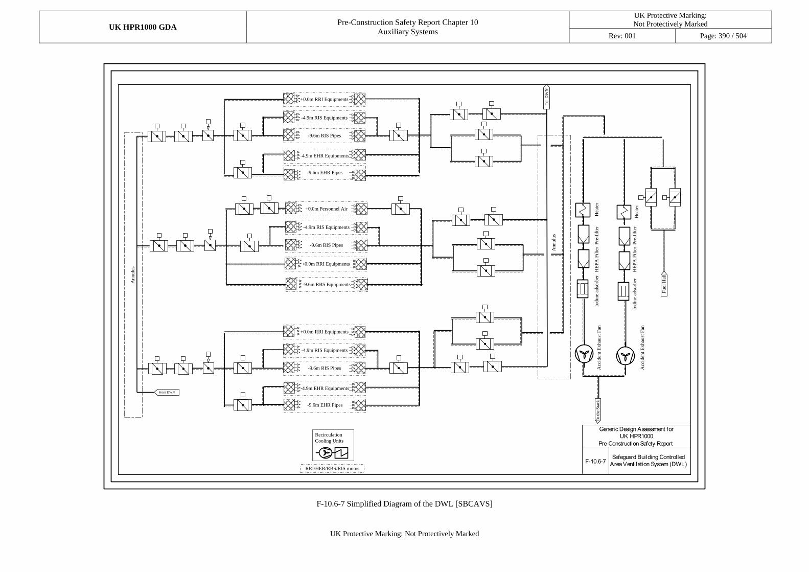
UK HPR1000 GDA Pre-Construction Safety Report Chapter 10
Auxiliary Systems
UK Protective Marking:
Not Protectively Marked
Rev: 001 Page: 390 / 504
UK Protective Marking: Not Protectively Marked
+0.0m RRI Equipments
-4.9m RIS Equipments
-9.6m RIS Pipes
-4.9m EHR Equipments
-9.6m EHR Pipes
+0.0m RRI Equipments
-4.9m RIS Equipments
-9.6m RIS Pipes
-4.9m EHR Equipments
-9.6m EHR Pipes
+0.0m Personnel Air
-4.9m RIS Equipments
-9.6m RIS Pipes
+0.0m RRI Equipments
Annulu
s
From DWN
A
nnulu
s
To
D
WN
Fuel
Hal
l
To
th
e S
tack
-9.6m RBS Equipments
Recirculation
Cooling Units
RRI/HER/RBS/RIS rooms
Acc
iden
t E
xhau
st F
an
Acc
iden
t E
xhau
st F
an
Pre
-fil
ter
Pre
-fil
ter
HE
PA
Fil
ter
HE
PA
Fil
ter
Iodin
e ad
sorb
er
Iodin
e ad
sorb
er
Hea
ter
Hea
ter
Safeguard Building Controlled
Area Ventilation System (DWL)
Generic Design Assessment for
UK HPR1000
Pre-Construction Safety Report
F-10.6-7
F-10.6-7 Simplified Diagram of the DWL [SBCAVS]
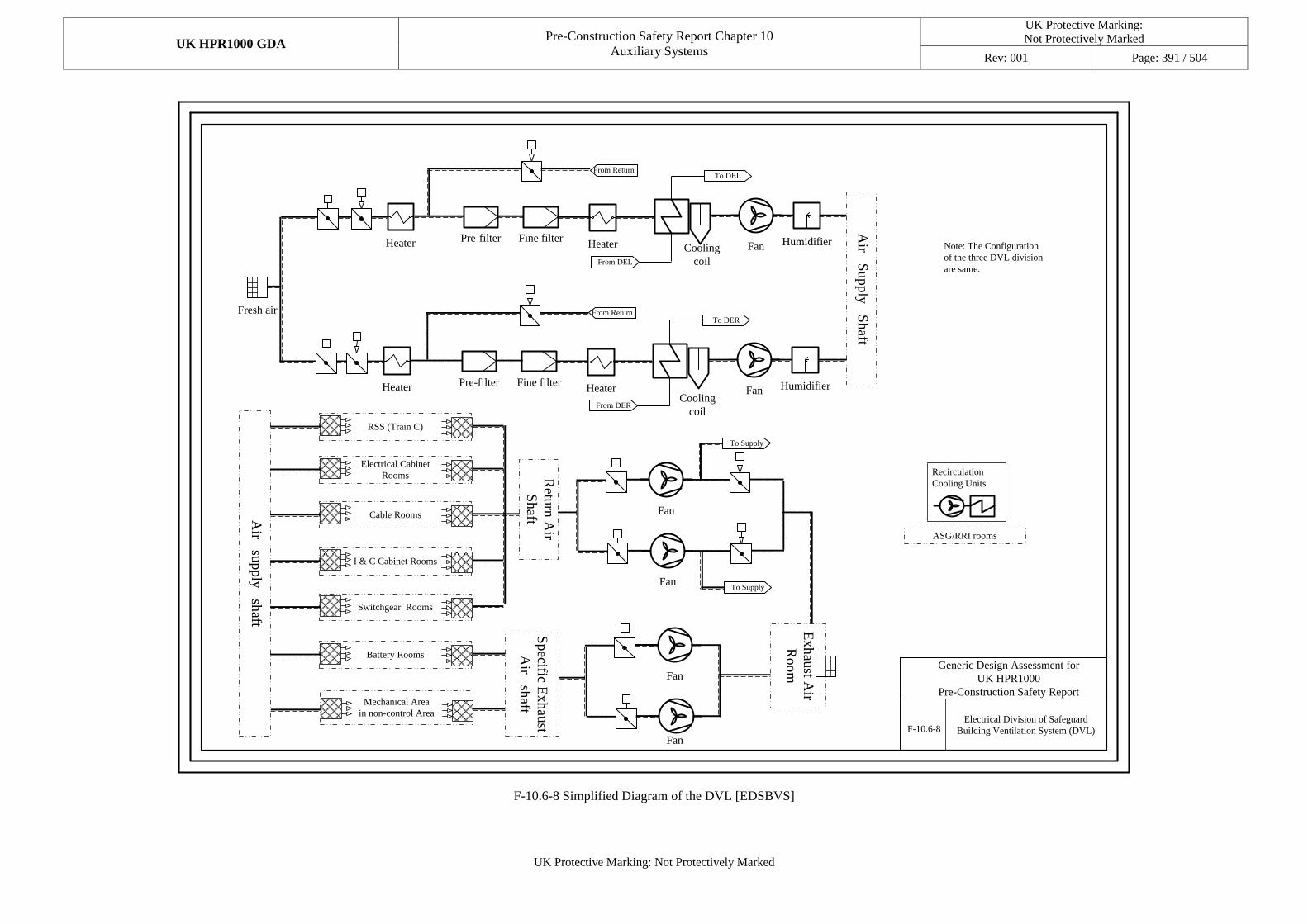
UK HPR1000 GDA Pre-Construction Safety Report Chapter 10
Auxiliary Systems
UK Protective Marking:
Not Protectively Marked
Rev: 001 Page: 391 / 504
UK Protective Marking: Not Protectively Marked
Electrical Division of Safeguard
Building Ventilation System (DVL)
Fresh air
HeaterPre-filter Fine filter
Fan Humidifier
Air S
up
ply
Sh
aft
From DEL
To DEL
HeaterPre-filter Fine filter
Fan Humidifier
From DER
To DER
Air su
pp
ly sh
aft
Retu
rn A
ir
Sh
aft
RSS (Train C)
Electrical Cabinet
Rooms
Cable Rooms
I & C Cabinet Rooms
Switchgear Rooms
Battery Rooms
Mechanical Area
in non-control Area
Sp
ecific Ex
hau
st
Air sh
aft
Fan
Fan
Fan
Ex
hau
st Air
Ro
om
F-10.6-8
From Return
From Return
To Supply
To Supply
Generic Design Assessment for
UK HPR1000
Pre-Construction Safety Report
Cooling
coil
Cooling
coil
Fan
Recirculation
Cooling Units
ASG/RRI rooms
Note: The Configuration
of the three DVL division
are same.
Heater
Heater
F-10.6-8 Simplified Diagram of the DVL [EDSBVS]
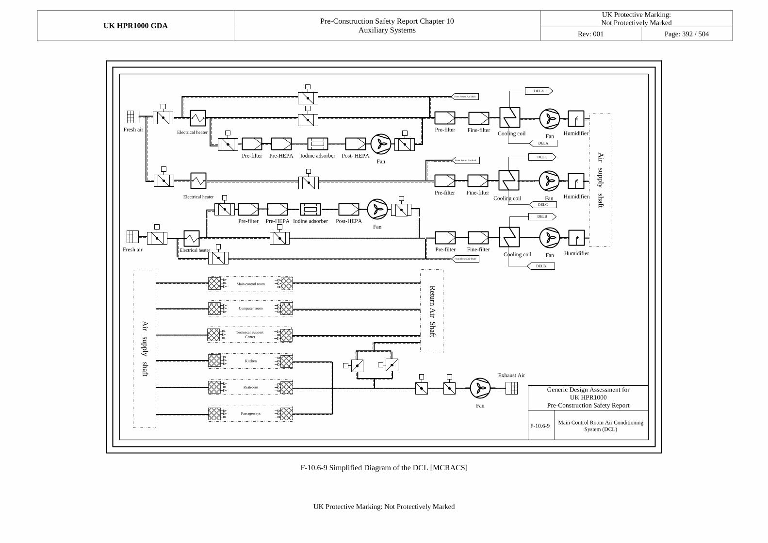
UK HPR1000 GDA Pre-Construction Safety Report Chapter 10
Auxiliary Systems
UK Protective Marking:
Not Protectively Marked
Rev: 001 Page: 392 / 504
UK Protective Marking: Not Protectively Marked
Fresh airElectrical heater
Pre-filter Pre-HEPA Iodine adsorberFan
Post- HEPA
Pre-filter Fine-filter
Fan
Humidifier
Air su
pply
shaft
From Return Air Shaft
Fresh air Electrical heater
Pre-filter Pre-HEPA Iodine adsorberFan
Post-HEPA
From Return Air Shaft
Pre-filter Fine-filter
Fan
Humidifier
Air su
pply
shaft
Retu
rn A
ir Shaft
Main control room
Computer room
Technical Support
Center
Kitchen
Restroom
Passageways
Fan
Exhaust Air
FanPre-filter Fine-filter
HumidifierElectrical heater
From Return Air Shaft
DELB
DELC
DELA
DELC
DELB
DELA
Main Control Room Air Conditioning
System (DCL)
Generic Design Assessment for
UK HPR1000
Pre-Construction Safety Report
F-10.6-9
Cooling coil
Cooling coil
Cooling coil
F-10.6-9 Simplified Diagram of the DCL [MCRACS]
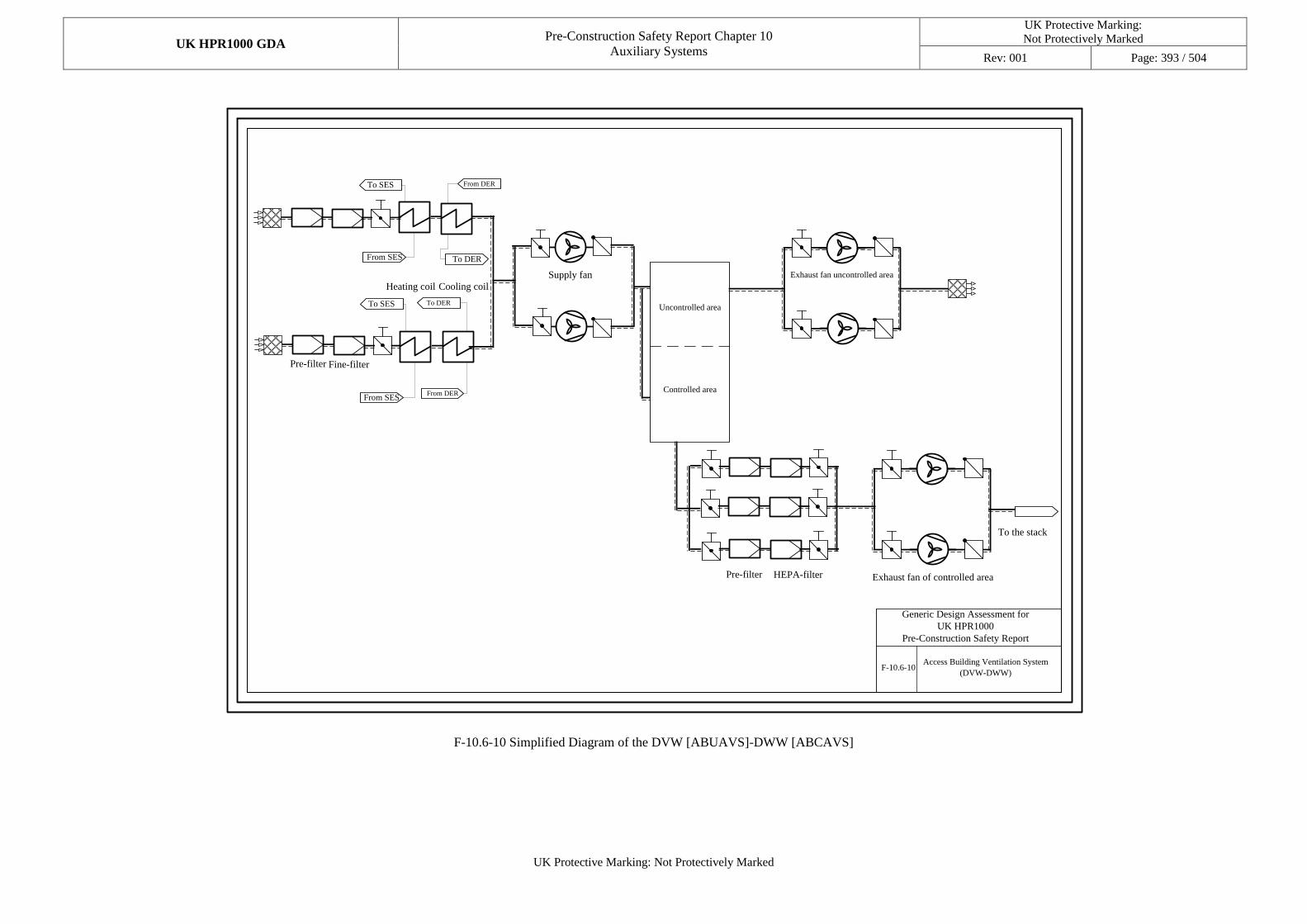
UK HPR1000 GDA Pre-Construction Safety Report Chapter 10
Auxiliary Systems
UK Protective Marking:
Not Protectively Marked
Rev: 001 Page: 393 / 504
UK Protective Marking: Not Protectively Marked
F-10.6-10Access Building Ventilation System
(DVW-DWW)
Supply fan Exhaust fan uncontrolled area
Exhaust fan of controlled area
Uncontrolled area
Generic Design Assessment for
UK HPR1000
Pre-Construction Safety Report
Pre-filter Fine-filter
Heating coil Cooling coil
Controlled area
To the stack
Pre-filter HEPA-filter
To SES
From SES
From DER
To DER
From SES
To SES To DER
From DER
F-10.6-10 Simplified Diagram of the DVW [ABUAVS]-DWW [ABCAVS]
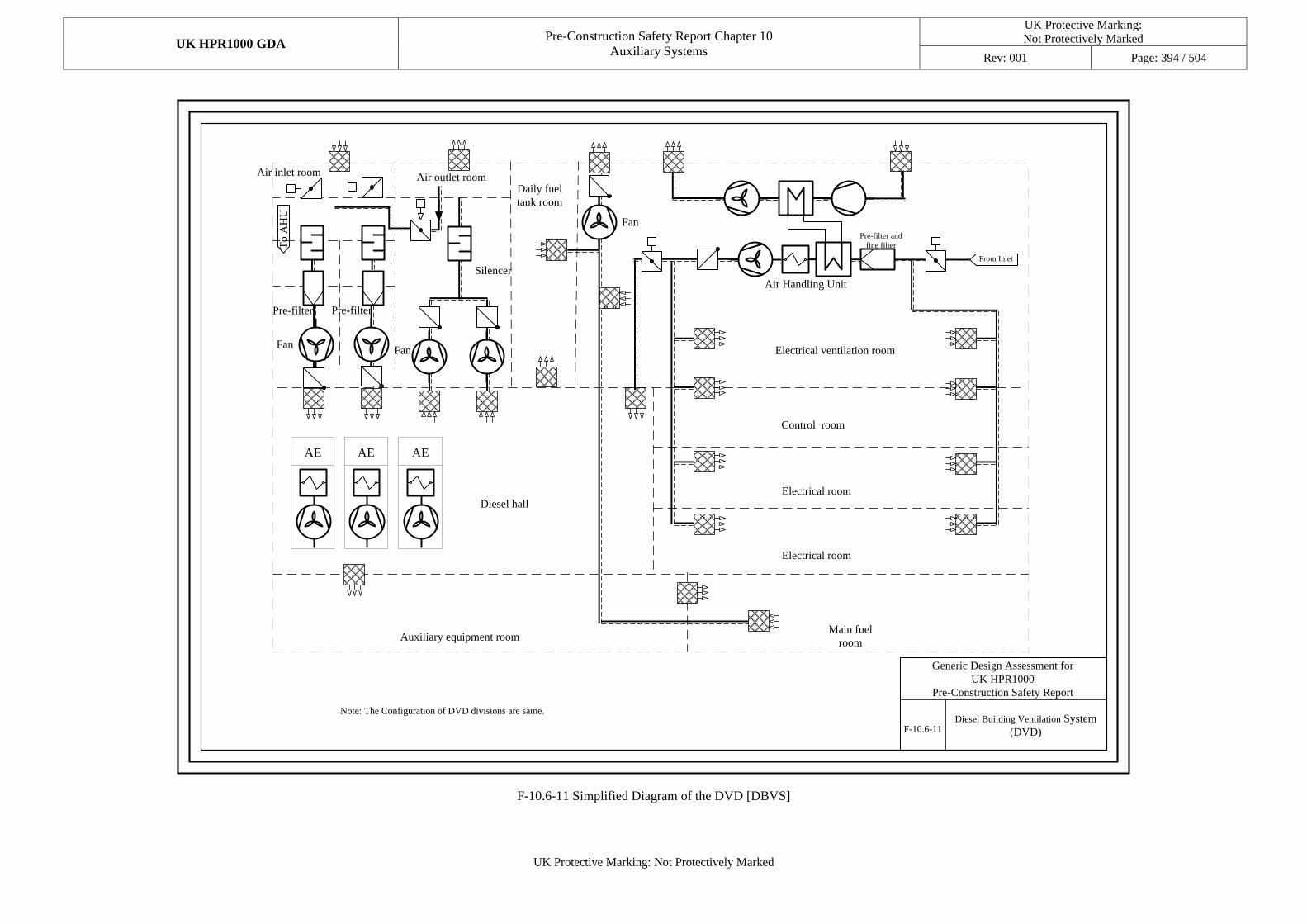
UK HPR1000 GDA Pre-Construction Safety Report Chapter 10
Auxiliary Systems
UK Protective Marking:
Not Protectively Marked
Rev: 001 Page: 394 / 504
UK Protective Marking: Not Protectively Marked
Diesel Building Ventilation System
(DVD)
Diesel hall
Auxiliary equipment room
Electrical room
Control room
Air outlet roomDaily fuel
tank room
Electrical ventilation room
Main fuel
room
Air inlet room
Electrical room
Fan
Fan
F-10.6-11
Generic Design Assessment for
UK HPR1000
Pre-Construction Safety Report
Air Handling Unit
Fan
SilencerT
o A
HU
From Inlet
Pre-filter and
fine filter
Note: The Configuration of DVD divisions are same.
AE AE AE
Pre-filter Pre-filter
F-10.6-11 Simplified Diagram of the DVD [DBVS]
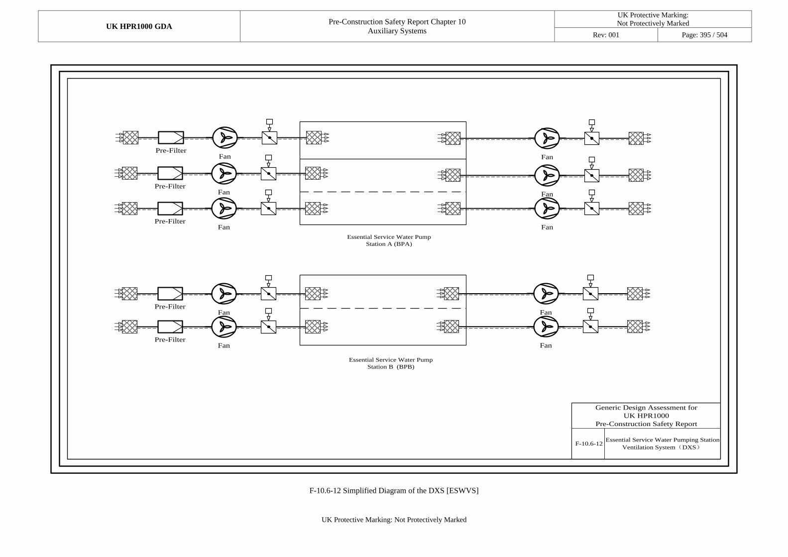
UK HPR1000 GDA Pre-Construction Safety Report Chapter 10
Auxiliary Systems
UK Protective Marking:
Not Protectively Marked
Rev: 001 Page: 395 / 504
UK Protective Marking: Not Protectively Marked
Essential Service Water Pump
Station A (BPA)
Essential Service Water Pump
Station B (BPB)
F-10.6-12
FanPre-Filter
FanPre-Filter
FanPre-Filter
Fan
Fan
Fan
FanPre-Filter
FanPre-Filter
Fan
Fan
Essential Service Water Pumping Station
Ventilation System(DXS)
Generic Design Assessment for
UK HPR1000
Pre-Construction Safety Report
F-10.6-12 Simplified Diagram of the DXS [ESWVS]
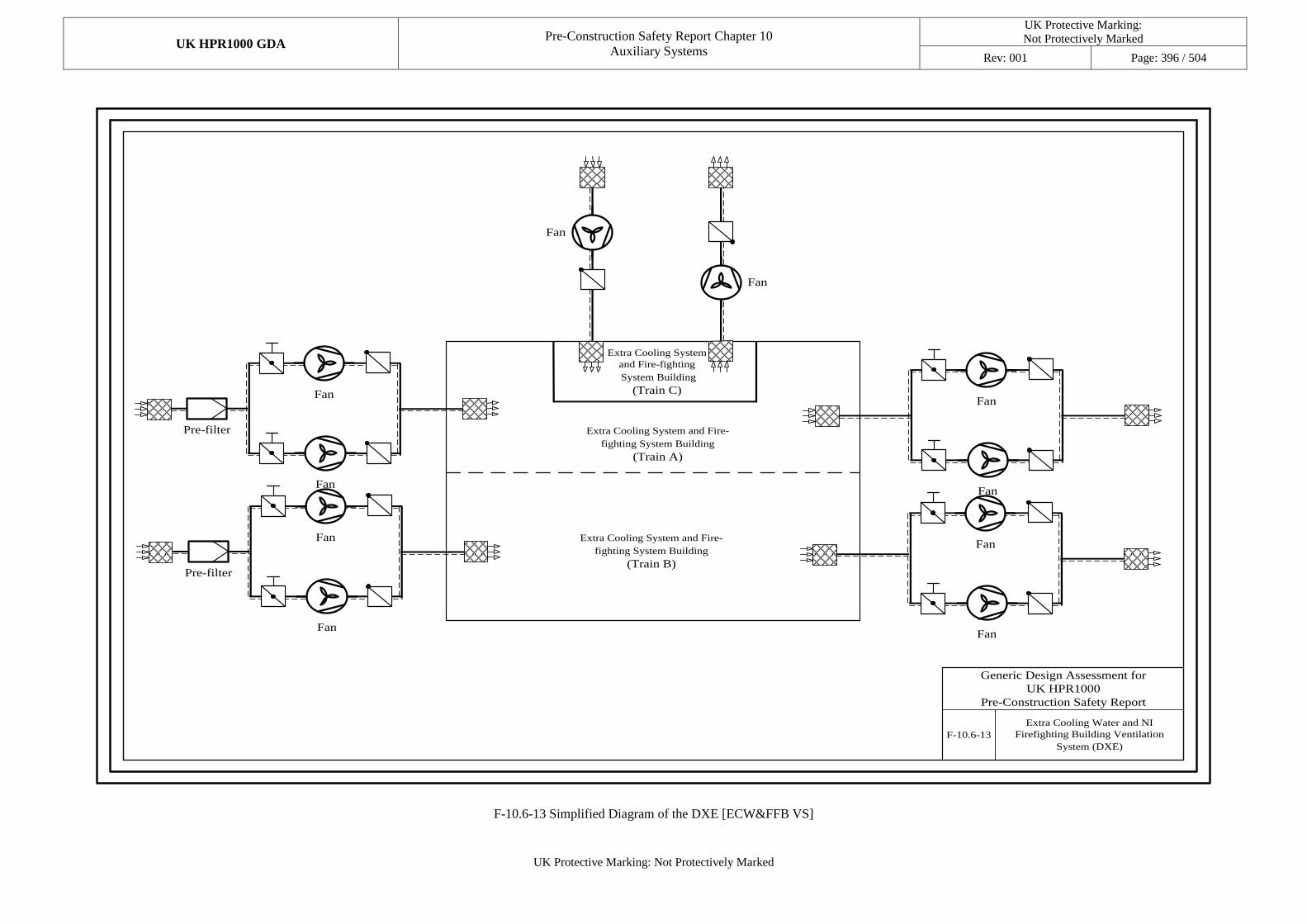
UK HPR1000 GDA Pre-Construction Safety Report Chapter 10
Auxiliary Systems
UK Protective Marking:
Not Protectively Marked
Rev: 001 Page: 396 / 504
UK Protective Marking: Not Protectively Marked
F-10.6-13
Extra Cooling Water and NI
Firefighting Building Ventilation
System (DXE)
Extra Cooling System and Fire-
fighting System Building
(Train A)
Extra Cooling System
and Fire-fighting
System Building
(Train C)
Fan
Fan
Pre-filter
Fan
Fan
Pre-filter
Fan
Fan
Fan
Fan
Fan
Fan
Extra Cooling System and Fire-
fighting System Building
(Train B)
Generic Design Assessment for
UK HPR1000
Pre-Construction Safety Report
F-10.6-13 Simplified Diagram of the DXE [ECW&FFB VS]
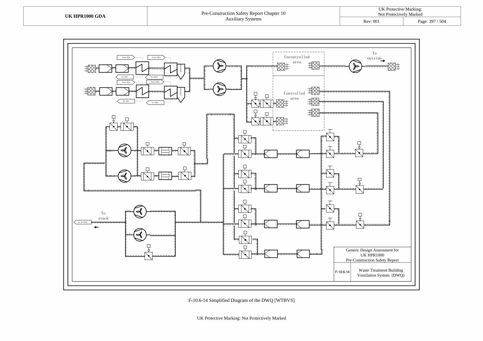
UK HPR1000 GDA Pre-Construction Safety Report Chapter 10
Auxiliary Systems
UK Protective Marking:
Not Protectively Marked
Rev: 001 Page: 397 / 504
UK Protective Marking: Not Protectively Marked
F-10.6-14
To stack
Uncontrolled area
Controlled area
To outside
Waste Treatment Building
Ventilation System (DWQ)
From SES
To SES
From SES
To SES
From DEQ
From DEQ
To DEQ
To DEQ
To the Stack
Generic Design Assessment for
UK HPR1000
Pre-Construction Safety Report
F-10.6-14 Simplified Diagram of the DWQ [WTBVS]
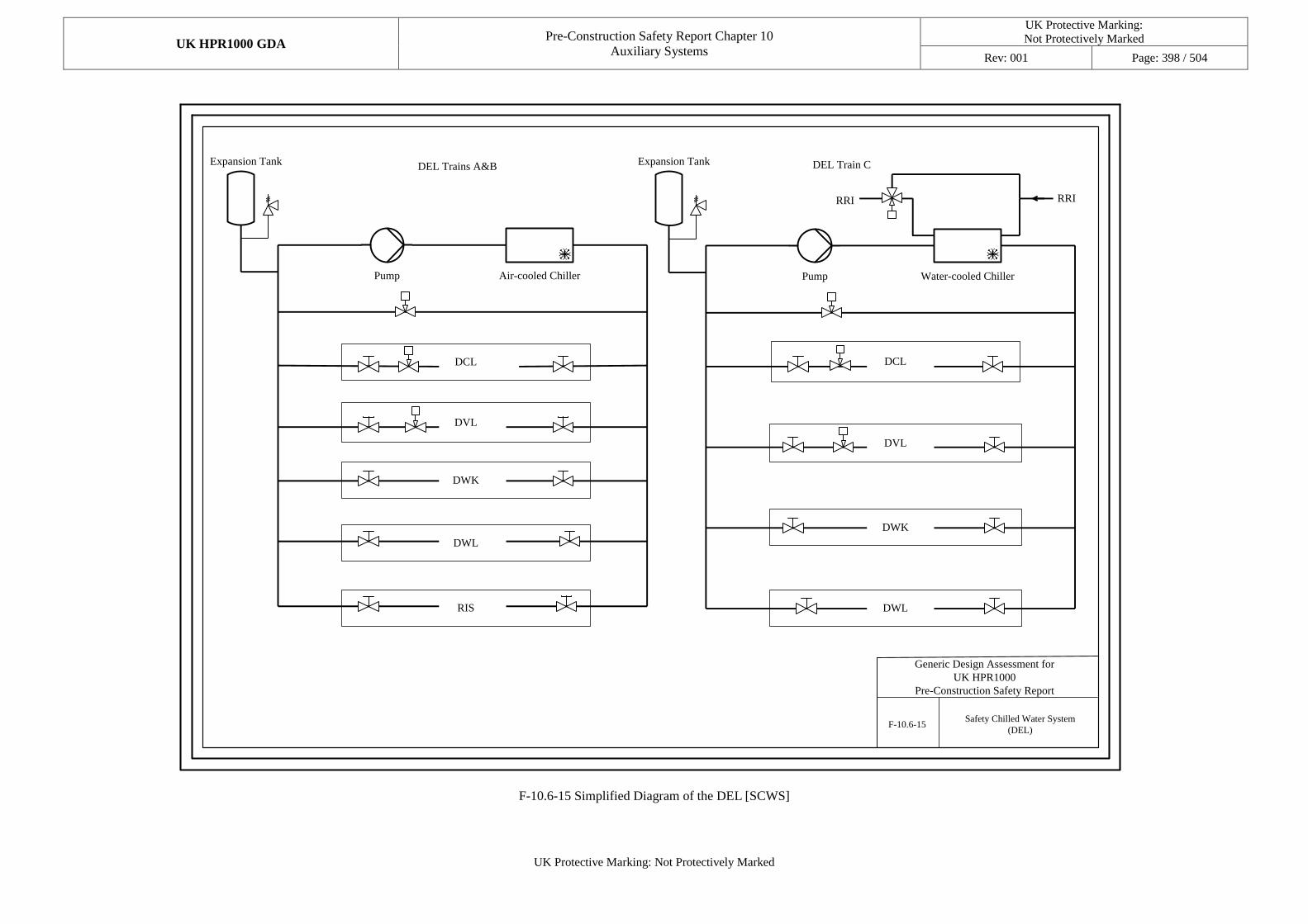
UK HPR1000 GDA Pre-Construction Safety Report Chapter 10
Auxiliary Systems
UK Protective Marking:
Not Protectively Marked
Rev: 001 Page: 398 / 504
UK Protective Marking: Not Protectively Marked
RIS
DWL
DVL
Expansion Tank
DWL
Water-cooled ChillerPump
DWK
DVL
Expansion Tank DEL Train C
RRIRRI
DCL
DWK
DCL
F-10.6-15Safety Chilled Water System
(DEL)
Pump Air-cooled Chiller
DEL Trains A&B
Generic Design Assessment for
UK HPR1000
Pre-Construction Safety Report
F-10.6-15 Simplified Diagram of the DEL [SCWS]
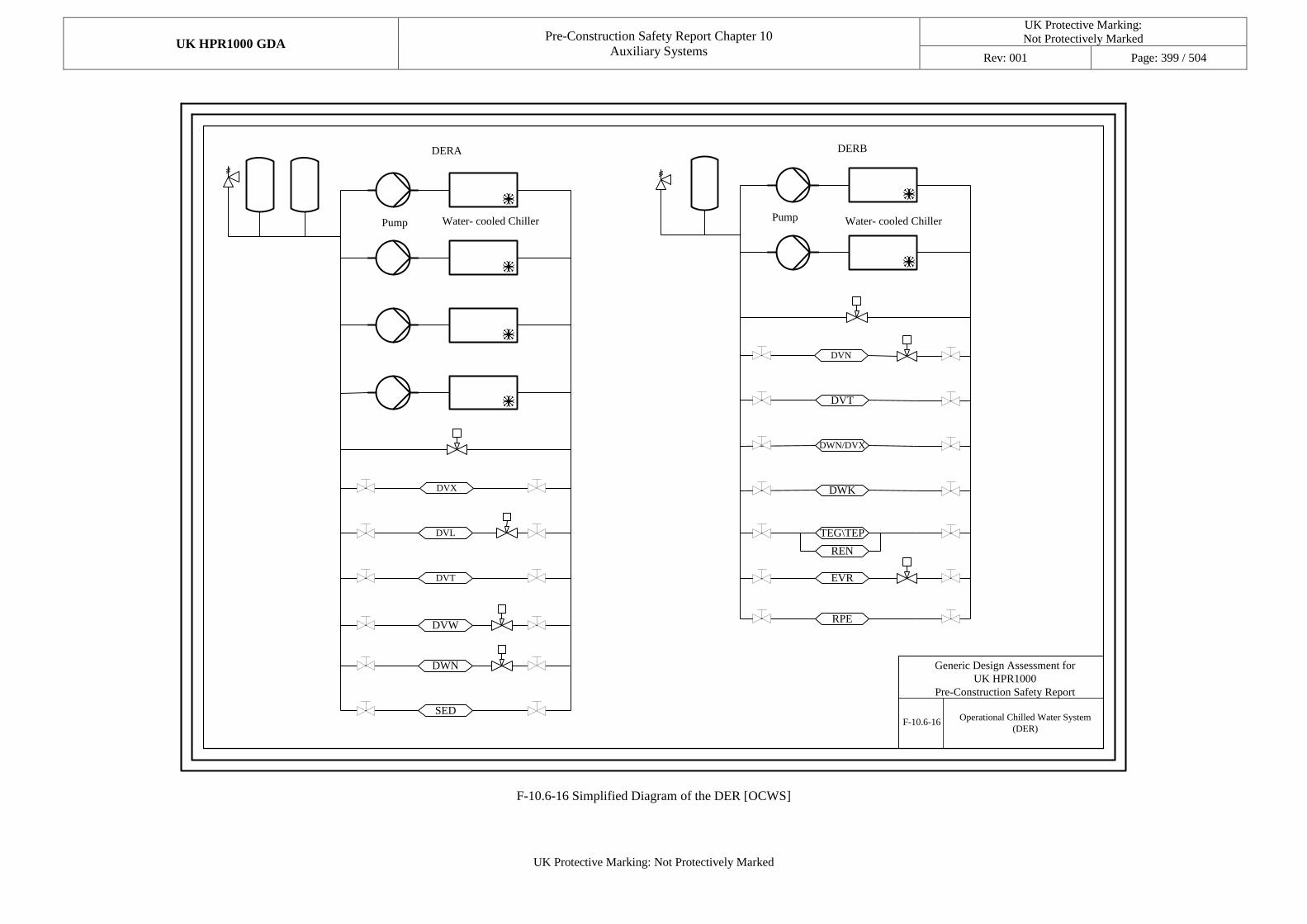
UK HPR1000 GDA Pre-Construction Safety Report Chapter 10
Auxiliary Systems
UK Protective Marking:
Not Protectively Marked
Rev: 001 Page: 399 / 504
UK Protective Marking: Not Protectively Marked
DERA DERB
DVX
DVW
DWN
DVN
DVT
DWN/DVX
DWK
EVR
RPE
TEG\TEP
REN
DVL
SED
DVT
Pump Water- cooled Chiller Pump Water- cooled Chiller
Operational Chilled Water System
(DER)F-10.6-16
Generic Design Assessment for
UK HPR1000
Pre-Construction Safety Report
F-10.6-16 Simplified Diagram of the DER [OCWS]
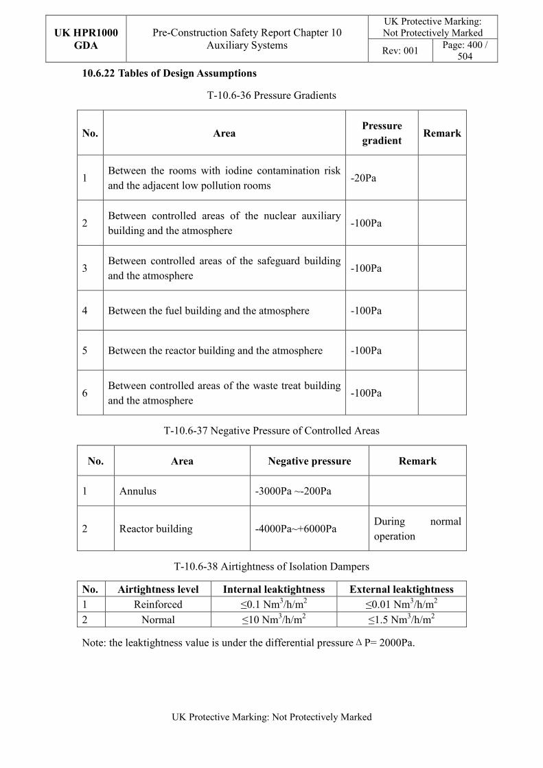
UK HPR1000
GDA
Pre-Construction Safety Report Chapter 10 Auxiliary Systems
UK Protective Marking: Not Protectively Marked
Rev: 001 Page: 400 /
504
UK Protective Marking: Not Protectively Marked
10.6.22 Tables of Design Assumptions
T-10.6-36 Pressure Gradients
No. Area Pressure
gradient Remark
1 Between the rooms with iodine contamination risk and the adjacent low pollution rooms
-20Pa
2 Between controlled areas of the nuclear auxiliary building and the atmosphere
-100Pa
3 Between controlled areas of the safeguard building and the atmosphere
-100Pa
4 Between the fuel building and the atmosphere -100Pa
5 Between the reactor building and the atmosphere -100Pa
6 Between controlled areas of the waste treat building and the atmosphere
-100Pa
T-10.6-37 Negative Pressure of Controlled Areas
No. Area Negative pressure Remark
1 Annulus -3000Pa ~-200Pa
2 Reactor building -4000Pa~+6000Pa During normal operation
T-10.6-38 Airtightness of Isolation Dampers
No. Airtightness level Internal leaktightness External leaktightness
1 Reinforced ≤0.1 Nm3/h/m2 ≤0.01 Nm3/h/m2
2 Normal ≤10 Nm3/h/m2 ≤1.5 Nm3/h/m2
Note: the leaktightness value is under the differential pressureΔP= 2000Pa.
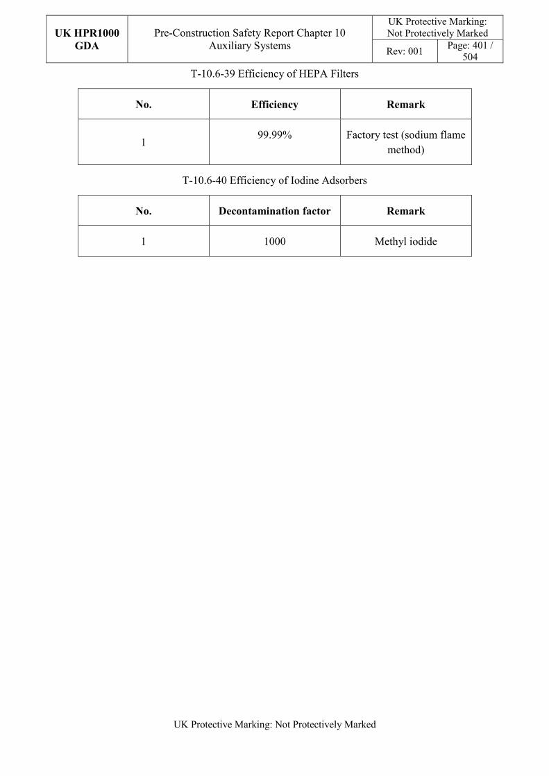
UK HPR1000
GDA
Pre-Construction Safety Report Chapter 10 Auxiliary Systems
UK Protective Marking: Not Protectively Marked
Rev: 001 Page: 401 /
504
UK Protective Marking: Not Protectively Marked
T-10.6-39 Efficiency of HEPA Filters
No. Efficiency Remark
1 99.99% Factory test (sodium flame
method)
T-10.6-40 Efficiency of Iodine Adsorbers
No. Decontamination factor Remark
1 1000 Methyl iodide
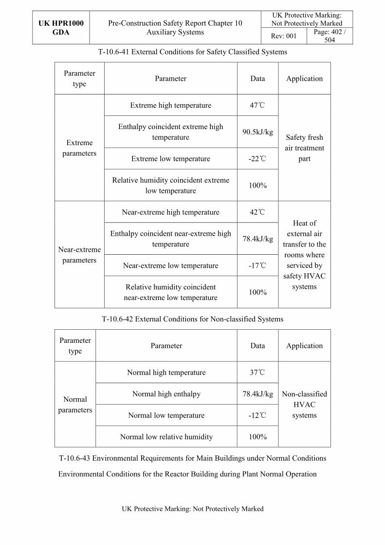
UK HPR1000
GDA
Pre-Construction Safety Report Chapter 10 Auxiliary Systems
UK Protective Marking: Not Protectively Marked
Rev: 001 Page: 402 /
504
UK Protective Marking: Not Protectively Marked
T-10.6-41 External Conditions for Safety Classified Systems
Parameter type
Parameter Data Application
Extreme parameters
Extreme high temperature 47℃
Safety fresh air treatment
part
Enthalpy coincident extreme high temperature
90.5kJ/kg
Extreme low temperature -22℃
Relative humidity coincident extreme low temperature
100%
Near-extreme parameters
Near-extreme high temperature 42℃
Heat of external air
transfer to the rooms where serviced by
safety HVAC systems
Enthalpy coincident near-extreme high temperature
78.4kJ/kg
Near-extreme low temperature -17℃
Relative humidity coincident near-extreme low temperature
100%
T-10.6-42 External Conditions for Non-classified Systems
Parameter type
Parameter Data Application
Normal parameters
Normal high temperature 37℃
Non-classified HVAC systems
Normal high enthalpy 78.4kJ/kg
Normal low temperature -12℃
Normal low relative humidity 100%
T-10.6-43 Environmental Requirements for Main Buildings under Normal Conditions
Environmental Conditions for the Reactor Building during Plant Normal Operation
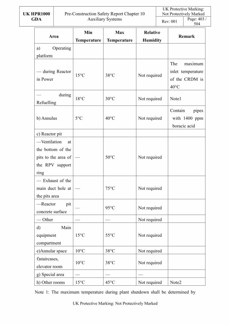
UK HPR1000
GDA
Pre-Construction Safety Report Chapter 10 Auxiliary Systems
UK Protective Marking: Not Protectively Marked
Rev: 001 Page: 403 /
504
UK Protective Marking: Not Protectively Marked
Area Min
Temperature
Max
Temperature
Relative
Humidity Remark
a) Operating
platform
— during Reactor
in Power 15°C 38°C Not required
The maximum
inlet temperature
of the CRDM is
40°C
— during
Refuelling 18°C 30°C Not required Note1
b) Annulus 5°C 40°C Not required
Contain pipes
with 1400 ppm
boracic acid
c) Reactor pit
—Ventilation at
the bottom of the
pits to the area of
the RPV support
ring
— 50°C Not required
— Exhaust of the
main duct hole at
the pits area
— 75°C Not required
—Reactor pit
concrete surface — 95°C Not required
— Other — — Not required
d) Main
equipment
compartment
15°C 55°C Not required
e)Annular space 10°C 38°C Not required
f)staircases,
elevator room 10°C 38°C Not required
g) Special area — — —
h) Other rooms 15°C 45°C Not required Note2
Note 1: The maximum temperature during plant shutdown shall be determined by
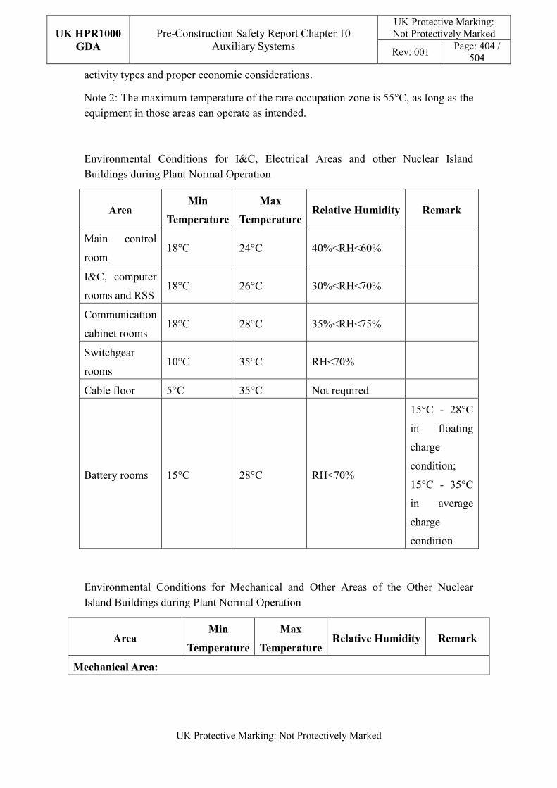
UK HPR1000
GDA
Pre-Construction Safety Report Chapter 10 Auxiliary Systems
UK Protective Marking: Not Protectively Marked
Rev: 001 Page: 404 /
504
UK Protective Marking: Not Protectively Marked
activity types and proper economic considerations.
Note 2: The maximum temperature of the rare occupation zone is 55°C, as long as the equipment in those areas can operate as intended.
Environmental Conditions for I&C, Electrical Areas and other Nuclear Island Buildings during Plant Normal Operation
Area Min
Temperature
Max
Temperature Relative Humidity Remark
Main control
room 18°C 24°C 40%<RH<60%
I&C, computer
rooms and RSS 18°C 26°C 30%<RH<70%
Communication
cabinet rooms 18°C 28°C 35%<RH<75%
Switchgear
rooms 10°C 35°C RH<70%
Cable floor 5°C 35°C Not required
Battery rooms 15°C 28°C RH<70%
15°C - 28°C
in floating
charge
condition;
15°C - 35°C
in average
charge
condition
Environmental Conditions for Mechanical and Other Areas of the Other Nuclear Island Buildings during Plant Normal Operation
Area Min
Temperature
Max
Temperature Relative Humidity Remark
Mechanical Area:
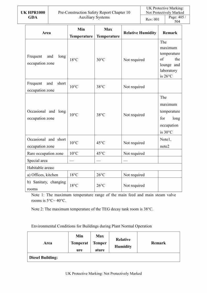
UK HPR1000
GDA
Pre-Construction Safety Report Chapter 10 Auxiliary Systems
UK Protective Marking: Not Protectively Marked
Rev: 001 Page: 405 /
504
UK Protective Marking: Not Protectively Marked
Area Min
Temperature
Max
Temperature Relative Humidity Remark
Frequent and long
occupation zone 18°C 30°C Not required
The maximum temperature of the lounge and laboratory is 26°C
Frequent and short
occupation zone 10°C 38°C Not required
Occasional and long
occupation zone 10°C 38°C Not required
The
maximum
temperature
for long
occupation
is 30°C
Occasional and short
occupation zone 10°C 45°C Not required
Note1,
note2
Rare occupation zone 10°C 45°C Not required
Special area — — —
Habitable areas:
a) Offices, kitchen 18°C 26°C Not required
b) Sanitary, changing
rooms 18°C 26°C Not required
Note 1: The maximum temperature range of the main feed and main steam valve rooms is 5°C~ 40°C.
Note 2: The maximum temperature of the TEG decay tank room is 38°C.
Environmental Conditions for Buildings during Plant Normal Operation
Area
Min
Temperat
ure
Max
Temper
ature
Relative
Humidity Remark
Diesel Building:
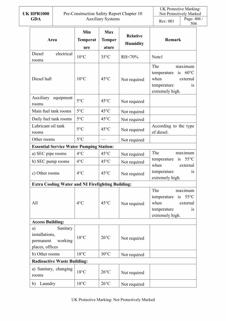
UK HPR1000
GDA
Pre-Construction Safety Report Chapter 10 Auxiliary Systems
UK Protective Marking: Not Protectively Marked
Rev: 001 Page: 406 /
504
UK Protective Marking: Not Protectively Marked
Area
Min
Temperat
ure
Max
Temper
ature
Relative
Humidity Remark
Diesel electrical rooms
10°C 35°C RH<70% Note1
Diesel hall 10°C 45°C Not required
The maximum temperature is 60°C when external temperature is extremely high.
Auxiliary equipment rooms
5°C 45°C Not required
Main fuel tank rooms 5°C 45°C Not required
Daily fuel tank rooms 5°C 45°C Not required
Lubricant oil tank rooms
5°C 45°C Not required According to the type of diesel.
Other rooms 5°C — Not required
Essential Service Water Pumping Station:
a) SEC pipe rooms 4°C 45°C Not required The maximum temperature is 55°C when external temperature is extremely high.
b) SEC pump rooms 4°C 45°C Not required
c) Other rooms 4°C 45°C Not required
Extra Cooling Water and NI Firefighting Building:
All 4°C 45°C Not required
The maximum temperature is 55°C when external temperature is extremely high.
Access Building:
a) Sanitary installations, permanent working places, offices
18°C 26°C Not required
b) Other rooms 18°C 30°C Not required
Radioactive Waste Building:
a) Sanitary, changing rooms
18°C 26°C Not required
b) Laundry 18°C 26°C Not required
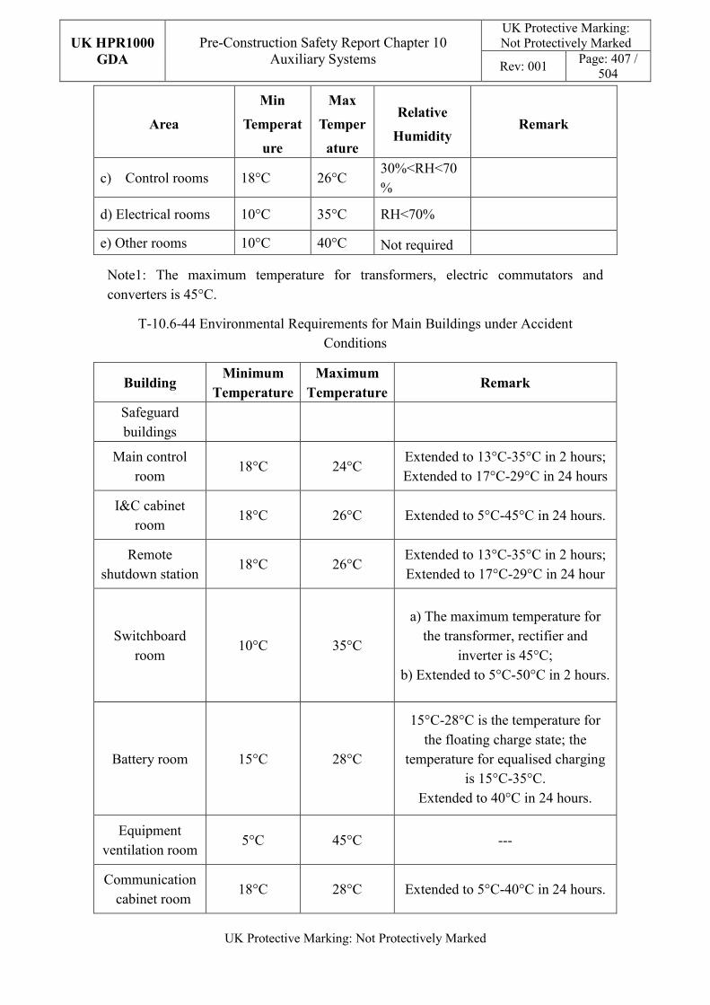
UK HPR1000
GDA
Pre-Construction Safety Report Chapter 10 Auxiliary Systems
UK Protective Marking: Not Protectively Marked
Rev: 001 Page: 407 /
504
UK Protective Marking: Not Protectively Marked
Area
Min
Temperat
ure
Max
Temper
ature
Relative
Humidity Remark
c) Control rooms 18°C 26°C 30%<RH<70%
d) Electrical rooms 10°C 35°C RH<70%
e) Other rooms 10°C 40°C Not required
Note1: The maximum temperature for transformers, electric commutators and converters is 45°C.
T-10.6-44 Environmental Requirements for Main Buildings under Accident Conditions
Building Minimum
Temperature
Maximum
Temperature Remark
Safeguard buildings
Main control room
18°C 24°C Extended to 13°C-35°C in 2 hours; Extended to 17°C-29°C in 24 hours
I&C cabinet room
18°C 26°C Extended to 5°C-45°C in 24 hours.
Remote shutdown station
18°C 26°C Extended to 13°C-35°C in 2 hours; Extended to 17°C-29°C in 24 hour
Switchboard room
10°C 35°C
a) The maximum temperature for the transformer, rectifier and
inverter is 45°C; b) Extended to 5°C-50°C in 2 hours.
Battery room 15°C 28°C
15°C-28°C is the temperature for the floating charge state; the
temperature for equalised charging is 15°C-35°C.
Extended to 40°C in 24 hours.
Equipment ventilation room
5°C 45°C ---
Communication cabinet room
18°C 28°C Extended to 5°C-40°C in 24 hours.
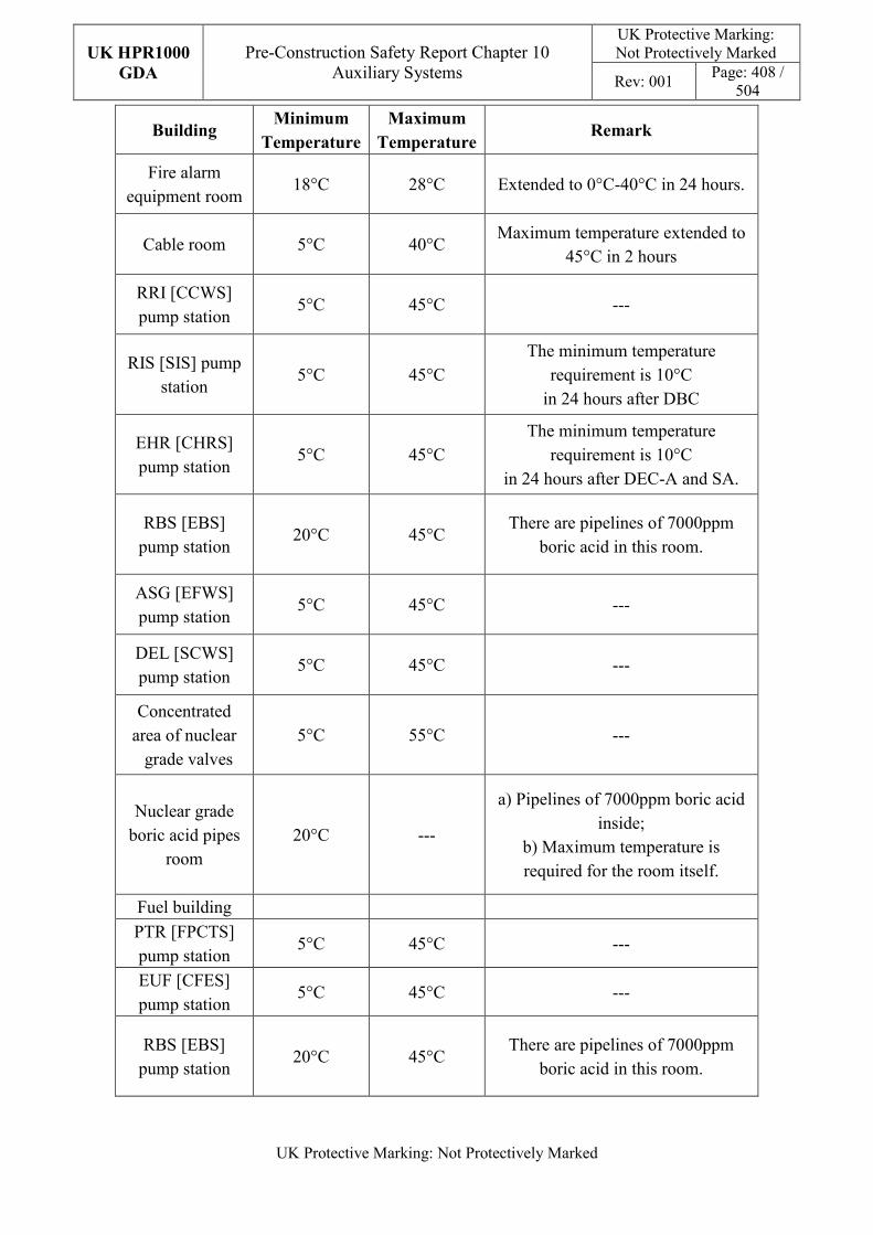
UK HPR1000
GDA
Pre-Construction Safety Report Chapter 10 Auxiliary Systems
UK Protective Marking: Not Protectively Marked
Rev: 001 Page: 408 /
504
UK Protective Marking: Not Protectively Marked
Building Minimum
Temperature
Maximum
Temperature Remark
Fire alarm equipment room
18°C 28°C Extended to 0°C-40°C in 24 hours.
Cable room 5°C 40°C Maximum temperature extended to
45°C in 2 hours
RRI [CCWS] pump station
5°C 45°C ---
RIS [SIS] pump station
5°C 45°C The minimum temperature
requirement is 10°C in 24 hours after DBC
EHR [CHRS] pump station
5°C 45°C The minimum temperature
requirement is 10°C in 24 hours after DEC-A and SA.
RBS [EBS] pump station
20°C 45°C There are pipelines of 7000ppm
boric acid in this room.
ASG [EFWS] pump station
5°C 45°C ---
DEL [SCWS] pump station
5°C 45°C ---
Concentrated area of nuclear grade valves
5°C 55°C ---
Nuclear grade boric acid pipes
room 20°C ---
a) Pipelines of 7000ppm boric acid inside;
b) Maximum temperature is required for the room itself.
Fuel building
PTR [FPCTS] pump station
5°C 45°C ---
EUF [CFES] pump station
5°C 45°C ---
RBS [EBS] pump station
20°C 45°C There are pipelines of 7000ppm
boric acid in this room.
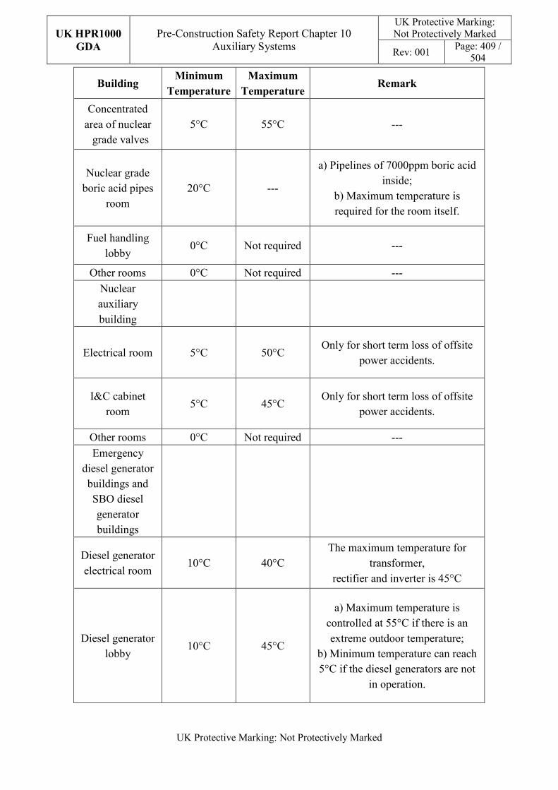
UK HPR1000
GDA
Pre-Construction Safety Report Chapter 10 Auxiliary Systems
UK Protective Marking: Not Protectively Marked
Rev: 001 Page: 409 /
504
UK Protective Marking: Not Protectively Marked
Building Minimum
Temperature
Maximum
Temperature Remark
Concentrated area of nuclear grade valves
5°C 55°C ---
Nuclear grade boric acid pipes
room 20°C ---
a) Pipelines of 7000ppm boric acid inside;
b) Maximum temperature is required for the room itself.
Fuel handling lobby
0°C Not required ---
Other rooms 0°C Not required ---
Nuclear auxiliary building
Electrical room 5°C 50°C Only for short term loss of offsite
power accidents.
I&C cabinet room
5°C 45°C Only for short term loss of offsite
power accidents.
Other rooms 0°C Not required ---
Emergency diesel generator buildings and SBO diesel generator buildings
Diesel generator electrical room
10°C 40°C The maximum temperature for
transformer, rectifier and inverter is 45°C
Diesel generator lobby
10°C 45°C
a) Maximum temperature is controlled at 55°C if there is an extreme outdoor temperature;
b) Minimum temperature can reach 5°C if the diesel generators are not
in operation.
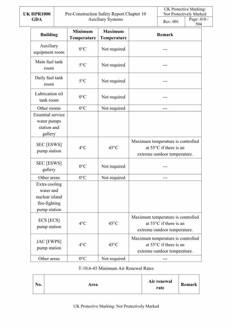
UK HPR1000
GDA
Pre-Construction Safety Report Chapter 10 Auxiliary Systems
UK Protective Marking: Not Protectively Marked
Rev: 001 Page: 410 /
504
UK Protective Marking: Not Protectively Marked
Building Minimum
Temperature
Maximum
Temperature Remark
Auxiliary equipment room
0°C Not required ---
Main fuel tank room
5°C Not required ---
Daily fuel tank room
5°C Not required ---
Lubrication oil tank room
0°C Not required ---
Other rooms 0°C Not required ---
Essential service water pumps station and
gallery
SEC [ESWS] pump station
4°C 45°C Maximum temperature is controlled
at 55°C if there is an extreme outdoor temperature.
SEC [ESWS] gallery
0°C Not required ---
Other areas 0°C Not required ---
Extra cooling water and
nuclear island fire-fighting pump station
ECS [ECS] pump station
4°C 45°C Maximum temperature is controlled
at 55°C if there is an extreme outdoor temperature.
JAC [FWPS] pump station
4°C 45°C Maximum temperature is controlled
at 55°C if there is an extreme outdoor temperature.
Other areas 0°C Not required ---
T-10.6-45 Minimum Air Renewal Rates
No. Area Air renewal
rate Remark
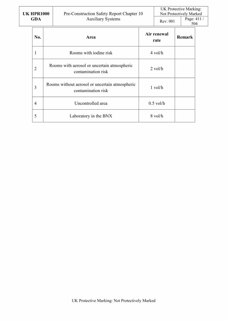
UK HPR1000
GDA
Pre-Construction Safety Report Chapter 10 Auxiliary Systems
UK Protective Marking: Not Protectively Marked
Rev: 001 Page: 411 /
504
UK Protective Marking: Not Protectively Marked
No. Area Air renewal
rate Remark
1 Rooms with iodine risk 4 vol/h
2 Rooms with aerosol or uncertain atmospheric
contamination risk 2 vol/h
3 Rooms without aerosol or uncertain atmospheric
contamination risk 1 vol/h
4 Uncontrolled area 0.5 vol/h
5 Laboratory in the BNX 8 vol/h
UK HPR1000
GDA
Pre-Construction Safety Report Chapter 10 Auxiliary Systems
UK Protective Marking: Not Protectively Marked
Rev: 001 Page: 412 /
504
UK Protective Marking: Not Protectively Marked
10.7 Fire Protection Systems
10.7.1 Sub-chapter Structure
The structure of Sub-chapter 10.7 is as follows:
a) Sub-chapter 10.7.1 (Sub-chapter Structure) gives the overall structure of Sub-chapter 10.7;
b) Sub-chapter 10.7.2 (Applicable Codes and Standards) presents the relative codes and standards adopted in this chapter;
c) Sub-chapters 10.7.3 to 10.7.5 present the following fire protection systems:
1) 10.7.3 Fire Alarm System;
2) 10.7.4 Fire-fighting System;
3) 10.7.5 Smoke Control System;
These sub-chapters give the detailed description of fire protection systems;
d) Sub-chapter 10.7.6 (ALARP Assessment) gives the preliminary ALARP analysis of this ub-chapter;
e) Sub-chapter 10.7.7 (Concluding Remarks) presents the summary and the on-going work of this sub-chapter;
10.7.2 Applicable Codes and Standards
The identification of applicable codes and standards in Sub-chapter 10.7 is compliant with the selection principles and the selection process stated in Chapter 4 and Reference [12].
Wherever possible, the standards applied for the engineering substantiation should be:
a) Internationally recognised in nuclear industry;
b) The latest or currently applicable approved standards; and
c) Consistent with the plant reliability goals necessary for safety.
Based on the above principles, the applicable codes and standards which are selected and used in Mechanical Engineering (ME) design are identified. During GDA step 3, the suitable analysis against the applicable codes and standards identified for the SSCs design in ME area are carried out in Reference [13]. The compliance analysis is carried out and presented in Reference [14]. Main applicable codes and standards for the fire protection systems and components design are presented in Table T-10.7-1.
Currently, the work of conformity analysis and gap analysis of the codes and standards is continuing.
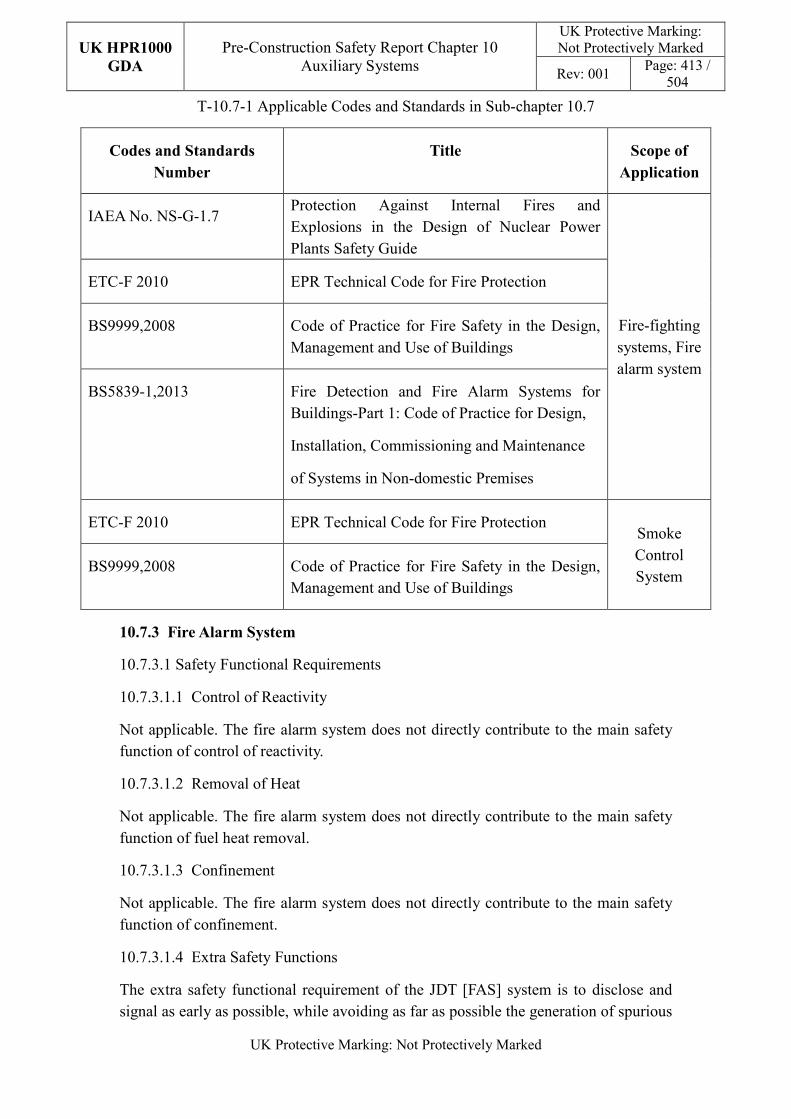
UK HPR1000
GDA
Pre-Construction Safety Report Chapter 10 Auxiliary Systems
UK Protective Marking: Not Protectively Marked
Rev: 001 Page: 413 /
504
UK Protective Marking: Not Protectively Marked
T-10.7-1 Applicable Codes and Standards in Sub-chapter 10.7
Codes and Standards
Number
Title Scope of
Application
IAEA No. NS-G-1.7 Protection Against Internal Fires and Explosions in the Design of Nuclear Power Plants Safety Guide
Fire-fighting systems, Fire alarm system
ETC-F 2010 EPR Technical Code for Fire Protection
BS9999,2008 Code of Practice for Fire Safety in the Design, Management and Use of Buildings
BS5839-1,2013 Fire Detection and Fire Alarm Systems for Buildings-Part 1: Code of Practice for Design,
Installation, Commissioning and Maintenance
of Systems in Non-domestic Premises
ETC-F 2010 EPR Technical Code for Fire Protection Smoke Control System
BS9999,2008 Code of Practice for Fire Safety in the Design, Management and Use of Buildings
10.7.3 Fire Alarm System
10.7.3.1 Safety Functional Requirements
10.7.3.1.1 Control of Reactivity
Not applicable. The fire alarm system does not directly contribute to the main safety function of control of reactivity.
10.7.3.1.2 Removal of Heat
Not applicable. The fire alarm system does not directly contribute to the main safety function of fuel heat removal.
10.7.3.1.3 Confinement
Not applicable. The fire alarm system does not directly contribute to the main safety function of confinement.
10.7.3.1.4 Extra Safety Functions
The extra safety functional requirement of the JDT [FAS] system is to disclose and signal as early as possible, while avoiding as far as possible the generation of spurious
UK HPR1000
GDA
Pre-Construction Safety Report Chapter 10 Auxiliary Systems
UK Protective Marking: Not Protectively Marked
Rev: 001 Page: 414 /
504
UK Protective Marking: Not Protectively Marked
alarms, an incipient fire in order to reduce the time to take suitable manual or automatic measures for fire fighting. Detailed information is presented in Reference [157].
10.7.3.2 Design Requirements
The general design requirements of the fire alarm system which need to be considered are shown in Sub-chapter 10.2.4. The following requirements are not applicable for the fire alarm system:
a) Autonomy in Respect of Heat Sink
Not applicable, because the JDT [FAS] doesn’t provide a heat sink to the power plant.
b) Prevention of Harmful Interactions of Systems Important to Safety
Not applicable, because the JDT [FAS] doesn’t have harmful interactions of systems important to safety.
c) Insulation
Not applicable, because the JDT [FAS] doesn’t have insulation design.
The substantiation analysis of the JDT [FAS] system to other design requirements is shown in Sub-chapter 10.7.3.5.
10.7.3.3 Design Bases
10.7.3.3.1 General Assumptions
a) Safety Classification
The JDT [FAS] system is used to protect against the fire impact, therefore the safety classification is FC3.
b) Ageing and Degradation
The components of the fire alarm systems don not need to be designed for the 60 years plant operation. Some components will need to be replaced at the end of their individual design life. The layout design will take into consideration the need to remove old parts and to install the replacements.
c) Considerations Related to the Electrical Power Grid
Not applicable.
10.7.3.3.2 Design Assumptions
This sub-chapter presents the main design assumptions considered in the system design.
UK HPR1000
GDA
Pre-Construction Safety Report Chapter 10 Auxiliary Systems
UK Protective Marking: Not Protectively Marked
Rev: 001 Page: 415 /
504
UK Protective Marking: Not Protectively Marked
a) Control of Reactivity
There is no quantitative safety-related design assumption for JDT [FAS].
b) Removal of Heat
There is no quantitative safety-related design assumption for JDT [FAS].
c) Confinement
There is no quantitative safety-related design assumption for JDT [FAS].
d) Extra Safety Functions
The fire alarm system is designed to be permanently in operation. The fire alarm system shall be ready to transmit a fire alarm or a disturbance signal in the MCR, and the system is supplied by a main or a secondary source.
The fire alarm system is designed to be able to ensure:
- The rapid detection of fires starting.
- The location of the fire source.
- The monitoring of the fire progress.
- The triggering of an alarm and in some cases, the indirect control of the fire dampers and smoke vents.
The hydrogen detection system is designed to be able to ensure the rapid detection of hydrogen leakage and accumulation.
10.7.3.4 System Description and Operation
10.7.3.4.1 System Description
a) General System Description
The fire alarm system can continuously monitor the plant through fire detectors that are placed at various places within the plant. The system can quickly detect fires, automatically activate alarms, provide the exact location of a fire and monitor the development of the fire. The fire alarm system can initiate automatic actions when necessary. Fire alarm control units provide the Centralised I&C systems with all the fire information required for the operation of the fire protection system in the NI. The signal is confirmed by double detection. Detailed information is presented in Reference [188].
The fire alarm system provides audible and/or visual alarms in the MCR.
The hydrogen detection system can quickly detect hydrogen accumulation, automatically activate alarms.
UK HPR1000
GDA
Pre-Construction Safety Report Chapter 10 Auxiliary Systems
UK Protective Marking: Not Protectively Marked
Rev: 001 Page: 416 /
504
UK Protective Marking: Not Protectively Marked
b) Description of Main Equipment
1) Fire Detectors
Fire detectors are located at fixed points in various areas of the plant which are divided into detection zones.
The type of detector at each location is chosen with respect to the particular fire phenomena applicable to the equipment or location being monitored (temperature, flame, smoke, combustion gas, etc.) and to the accessibility and atmospheric conditions of its installation.
The following types of fire detectors are typically used:
- Smoke detector.
- Flame detector.
- Heat detector.
- Line-type heat detector.
- Aspirating smoke detector.
- Hydrogen detector.
2) Fire Alarm Control Unit
The fire alarm control unit performs the fire alarm and fault alarm functions, and issues different audible and visual alarm signals in the event of a fire alarm and fault alarm. The fire alarm control unit is able to store and retrieve the alarm information. Fire detectors are linked to the fire alarm control unit.
3) Remote Control Unit
The remote control unit is located in the MCR and is used for centralised indication and operations of the fire alarm units.
4) Supervisor
The supervisor is located in the MCR. It consists of a computer connected to the central fire alarm control units, and a monitor, to display the relevant information including audible and visible fire alarms, fire zoning drawings and location of the detector.
5) Local Mimic Panel
Nuclear island buildings are equipped with local mimic panels, which indicate the location of the room where a fire has started. These panels help to locate the origin of the fire.
6) Hydrogen Detection Control Unit
UK HPR1000
GDA
Pre-Construction Safety Report Chapter 10 Auxiliary Systems
UK Protective Marking: Not Protectively Marked
Rev: 001 Page: 417 /
504
UK Protective Marking: Not Protectively Marked
The hydrogen alarm control unit performs the hydrogen alarm and fault alarm functions, and issues different audible and visual alarm signals in the event of alarm and fault alarm. The hydrogen alarm control unit is able to store and retrieve the alarm information. Hydrogen detectors are linked to the hydrogen alarm control unit.
c) Description of Main Layout
1) Fire alarm control unit
Fire alarm control units are set according to the trains. A master control unit and redundant control unit are set for each train. Fire alarm control units are set in the JDT cabinet rooms in Safeguard Buildings.
2) Remote control unit
The remote control units are installed in the MCR.
3) Supervisor
The supervisors are installed in the MCR, the Remote Shutdown Station and the maintenance room.
4) Local mimic panel
Local mimic panels are set in the main entrance or evacuation passageway of the buildings.
5) Fire detectors
Each area with a fire risk is equipped with detection. Detailed information is presented in Reference [189].
d) Description of System Interfaces
The DCL [MCRACS] and DVL [EDSBVS] are the support systems of JDT [FAS], which safeguard the operation environment of the main JDT equipment.
The DCL [MCRACS], DVL [EDSBVS], DVD [DBVS], DVW [ABUAVS], DWK [FBVS], DWL [SBCAVS], DWN [NABVS], DWQ [WTBVS], DWW [ABCAVS], EBA [CSBVS], EVF [CIFS], JPI [FWSNI] are the systems served by the JDT. The information transfer between the JDT [FAS] and served systems is achieved by Centralised I&C systems.
e) Description of Instrumentation and Control
The JDT [FAS] has the function of automatic and manual trigger the fire alarm. The signal can be sent to the fire alarm control unit, remote control unit, supervisor and local mimic panel. Fire alarm information can be confirmed and reset by fire control unit and remote control unit.
UK HPR1000
GDA
Pre-Construction Safety Report Chapter 10 Auxiliary Systems
UK Protective Marking: Not Protectively Marked
Rev: 001 Page: 418 /
504
UK Protective Marking: Not Protectively Marked
10.7.3.4.2 System Operation
a) Plant Normal Conditions
1) During Plant Normal Operation
The fire alarm system shall be permanently in service.
However, it is possible to switch off a part of the detection temporarily under certain conditions (such as for preventive maintenance).
2) During Plant Degraded Operation
In case of a lack of the 220V AC uninterrupted power supply, the main equipment of the fire alarm system is supplied from 24V storage batteries (24h) dedicated to fire detection. In of the event of earthquakes, the fire alarm system can be functional after a SSE. Detailed information is presented in Reference [158].
b) Plant Accident Conditions
The system alarm function shall not be affected in case of a single point loop breaking. Single detection equipment failure shall not affect the rest of the detection equipment.
Fire alarm control units are set up in trains. The failure of the fire alarm unit of one train shall not affect the operation of the rest of the units in other trains.
The functions associated with the fire alarm system will not work when the fire alarm system fails. Detailed information is presented in Reference [158].
10.7.3.5 Preliminary Design Substantiation
10.7.3.5.1 Compliance with Safety Functional Requirements
a) Control of Reactivity
Not applicable. The fire alarm system does not directly contribute to the main safety function of control of reactivity.
b) Removal of Heat
Not applicable. The fire alarm system does not directly contribute to the main safety function of fuel heat removal.
c) Confinement
Not applicable. The fire alarm system does not directly contribute to the main safety function of confinement.
d) Extra Safety Functions
The fire alarm system is implemented for detecting fire at an early stage, and is generally incorporated in all buildings. The system also triggers the fire alarm,
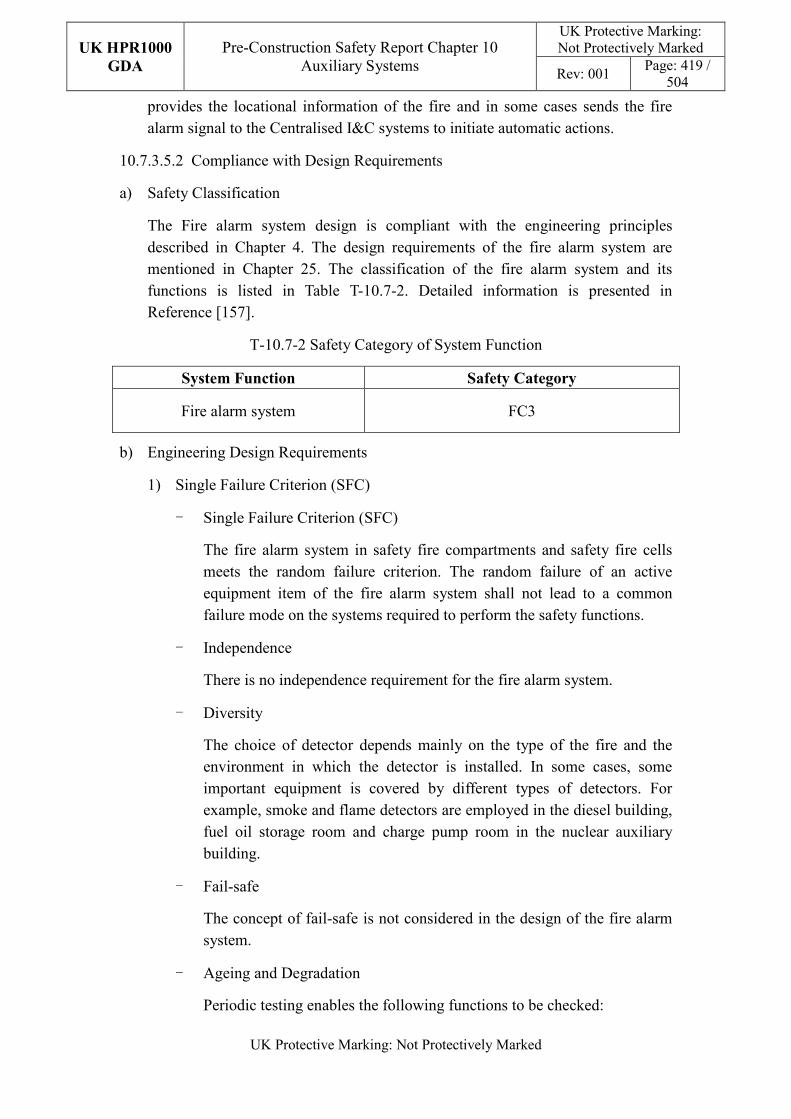
UK HPR1000
GDA
Pre-Construction Safety Report Chapter 10 Auxiliary Systems
UK Protective Marking: Not Protectively Marked
Rev: 001 Page: 419 /
504
UK Protective Marking: Not Protectively Marked
provides the locational information of the fire and in some cases sends the fire alarm signal to the Centralised I&C systems to initiate automatic actions.
10.7.3.5.2 Compliance with Design Requirements
a) Safety Classification
The Fire alarm system design is compliant with the engineering principles described in Chapter 4. The design requirements of the fire alarm system are mentioned in Chapter 25. The classification of the fire alarm system and its functions is listed in Table T-10.7-2. Detailed information is presented in Reference [157].
T-10.7-2 Safety Category of System Function
System Function Safety Category
Fire alarm system FC3
b) Engineering Design Requirements
1) Single Failure Criterion (SFC)
- Single Failure Criterion (SFC)
The fire alarm system in safety fire compartments and safety fire cells meets the random failure criterion. The random failure of an active equipment item of the fire alarm system shall not lead to a common failure mode on the systems required to perform the safety functions.
- Independence
There is no independence requirement for the fire alarm system.
- Diversity
The choice of detector depends mainly on the type of the fire and the environment in which the detector is installed. In some cases, some important equipment is covered by different types of detectors. For example, smoke and flame detectors are employed in the diesel building, fuel oil storage room and charge pump room in the nuclear auxiliary building.
- Fail-safe
The concept of fail-safe is not considered in the design of the fire alarm system.
- Ageing and Degradation
Periodic testing enables the following functions to be checked:
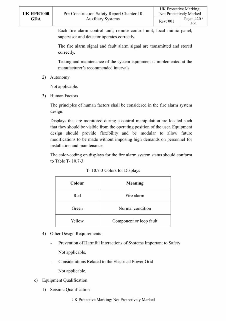
UK HPR1000
GDA
Pre-Construction Safety Report Chapter 10 Auxiliary Systems
UK Protective Marking: Not Protectively Marked
Rev: 001 Page: 420 /
504
UK Protective Marking: Not Protectively Marked
Each fire alarm control unit, remote control unit, local mimic panel, supervisor and detector operates correctly.
The fire alarm signal and fault alarm signal are transmitted and stored correctly.
Testing and maintenance of the system equipment is implemented at the manufacturer’s recommended intervals.
2) Autonomy
Not applicable.
3) Human Factors
The principles of human factors shall be considered in the fire alarm system design.
Displays that are monitored during a control manipulation are located such that they should be visible from the operating position of the user. Equipment design should provide flexibility and be modular to allow future modifications to be made without imposing high demands on personnel for installation and maintenance.
The color-coding on displays for the fire alarm system status should conform to Table T- 10.7-3.
T- 10.7-3 Colors for Displays
Colour Meaning
Red Fire alarm
Green Normal condition
Yellow Component or loop fault
4) Other Design Requirements
- Prevention of Harmful Interactions of Systems Important to Safety
Not applicable.
- Considerations Related to the Electrical Power Grid
Not applicable.
c) Equipment Qualification
1) Seismic Qualification
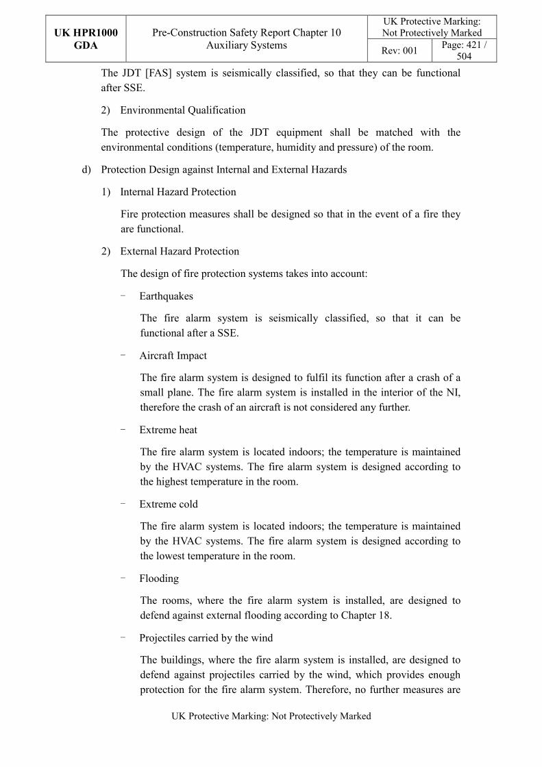
UK HPR1000
GDA
Pre-Construction Safety Report Chapter 10 Auxiliary Systems
UK Protective Marking: Not Protectively Marked
Rev: 001 Page: 421 /
504
UK Protective Marking: Not Protectively Marked
The JDT [FAS] system is seismically classified, so that they can be functional after SSE.
2) Environmental Qualification
The protective design of the JDT equipment shall be matched with the environmental conditions (temperature, humidity and pressure) of the room.
d) Protection Design against Internal and External Hazards
1) Internal Hazard Protection
Fire protection measures shall be designed so that in the event of a fire they are functional.
2) External Hazard Protection
The design of fire protection systems takes into account:
- Earthquakes
The fire alarm system is seismically classified, so that it can be functional after a SSE.
- Aircraft Impact
The fire alarm system is designed to fulfil its function after a crash of a small plane. The fire alarm system is installed in the interior of the NI, therefore the crash of an aircraft is not considered any further.
- Extreme heat
The fire alarm system is located indoors; the temperature is maintained by the HVAC systems. The fire alarm system is designed according to the highest temperature in the room.
- Extreme cold
The fire alarm system is located indoors; the temperature is maintained by the HVAC systems. The fire alarm system is designed according to the lowest temperature in the room.
- Flooding
The rooms, where the fire alarm system is installed, are designed to defend against external flooding according to Chapter 18.
- Projectiles carried by the wind
The buildings, where the fire alarm system is installed, are designed to defend against projectiles carried by the wind, which provides enough protection for the fire alarm system. Therefore, no further measures are
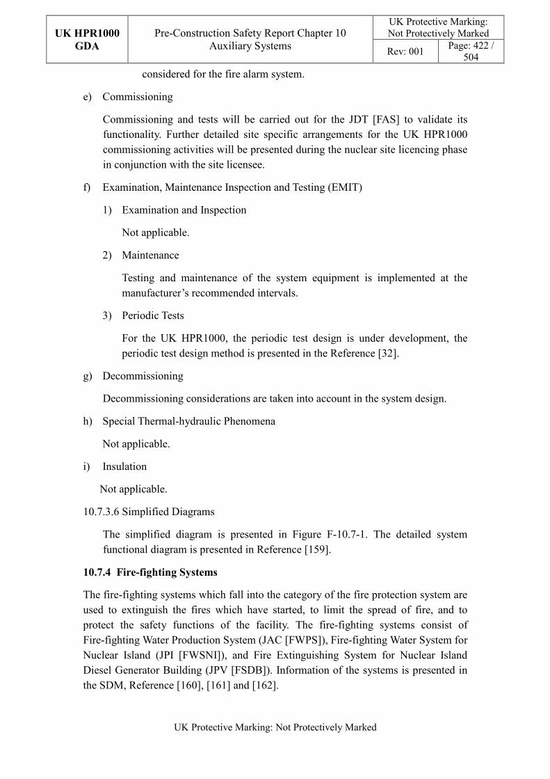
UK HPR1000
GDA
Pre-Construction Safety Report Chapter 10 Auxiliary Systems
UK Protective Marking: Not Protectively Marked
Rev: 001 Page: 422 /
504
UK Protective Marking: Not Protectively Marked
considered for the fire alarm system.
e) Commissioning
Commissioning and tests will be carried out for the JDT [FAS] to validate its functionality. Further detailed site specific arrangements for the UK HPR1000 commissioning activities will be presented during the nuclear site licencing phase in conjunction with the site licensee.
f) Examination, Maintenance Inspection and Testing (EMIT)
1) Examination and Inspection
Not applicable.
2) Maintenance
Testing and maintenance of the system equipment is implemented at the manufacturer’s recommended intervals.
3) Periodic Tests
For the UK HPR1000, the periodic test design is under development, the periodic test design method is presented in the Reference [32].
g) Decommissioning
Decommissioning considerations are taken into account in the system design.
h) Special Thermal-hydraulic Phenomena
Not applicable.
i) Insulation
Not applicable.
10.7.3.6 Simplified Diagrams
The simplified diagram is presented in Figure F-10.7-1. The detailed system functional diagram is presented in Reference [159].
10.7.4 Fire-fighting Systems
The fire-fighting systems which fall into the category of the fire protection system are used to extinguish the fires which have started, to limit the spread of fire, and to protect the safety functions of the facility. The fire-fighting systems consist of Fire-fighting Water Production System (JAC [FWPS]), Fire-fighting Water System for Nuclear Island (JPI [FWSNI]), and Fire Extinguishing System for Nuclear Island Diesel Generator Building (JPV [FSDB]). Information of the systems is presented in the SDM, Reference [160], [161] and [162].
UK HPR1000
GDA
Pre-Construction Safety Report Chapter 10 Auxiliary Systems
UK Protective Marking: Not Protectively Marked
Rev: 001 Page: 423 /
504
UK Protective Marking: Not Protectively Marked
10.7.4.1 Safety Functional Requirements
10.7.4.1.1 Control of Reactivity
Not applicable. The JAC [FWPS], JPI [FWSNI] and JPV [FSDB] do not directly contribute to the main safety function of control of reactivity.
10.7.4.1.2 Removal of Heat
Not applicable. The JAC [FWPS], JPI [FWSNI] and JPV [FSDB] do not directly contribute to the main safety function of heat removal.
10.7.4.1.3 Confinement
The containment isolation valves of the JPI [FWSNI] provide the basic safety function of “confinement of radioactive substances” to avoid dispersion of radiological substances outside of containment in DBC-2, DBC-3, DBC-4 or DEC. It contributes to the function of “ensuring the integrity of the containment”. The other parts of the JPI [FWSNI], JAC [FWPS] and JPV [FSDB] do not directly contribute to the main safety function of confinement.
10.7.4.1.4 Extra Safety Functional Requirement
a) Supporting the Fundamental Safety Functions
The fire-fighting tanks participate in emergency water supply for classified system in DEC-A.
If the JAC [FWPS] and JPI [FWSNI] are available, the JAC [FWPS] supports the RRI [CCWS] functions by providing water when the normal water supply system for the RRI [CCWS] is unavailable following a seismic event.
a) Protect and Mitigate Hazards Impact
1) Fire
The JAC [FWPS], JPI [FWSNI], JPV [FSDB] are used to extinguish fires, to limit the spread of fire, and to protect the safety functions of the facility.
An independent fire is postulated to be able to break out during the following cases, and the JAC [FWPS], JPI [FWSNI], JPV [FSDB] shall be available:
- The long term phase after reaching the safe shutdown state, after a DBC-2, DBC-3, DBC-4.
- In the post-accident long-term phase not earlier than two weeks after the DEC event.
- In the post-earthquake long-term phase not earlier than two weeks after a design basis earthquake (only the fire- fighting system for FC1 and FC2 functions needs need be available).
UK HPR1000
GDA
Pre-Construction Safety Report Chapter 10 Auxiliary Systems
UK Protective Marking: Not Protectively Marked
Rev: 001 Page: 424 /
504
UK Protective Marking: Not Protectively Marked
2) Earthquake
The JAC [FWPS], JPI [FWSNI], and JPV [FSDB] must ensure the stability/integrity of components in order to not adversely impact the availability of SSE1 items following a seismic event.
10.7.4.2 Design Requirements
The general design requirements of the fire-fighting systems which need to be considered are shown in Sub-chapter 10.2.4, among which the following requirements are not applicable for the fire-fighting system:
a) Autonomy in Respect of Heat Sink
Not applicable, because the JAC [FWPS], JPI [FWSNI], and JPV [FSDB] do not provide a heat sink to the power plant.
b) Prevention of Harmful Interactions of Systems Important to Safety
Not applicable, because the JAC [FWPS], JPI [FWSNI], and JPV [FSDB] do not have harmful interactions of systems important to safety.
c) Insulation
Not applicable, because the JAC [FWPS], JPI [FWSNI], and JPV [FSDB] do not have insulation design.
The substantiation analysis of the JAC [FWPS], JPI [FWSNI], and JPV [FSDB] to other design requirements is shown in the section 10.7.4.5.2.
10.7.4.3 Design Bases
10.7.4.3.1 General Assumptions
a) Safety Classification
The containment isolation valves of the JPI [FWSNI] must provide the basic safety function of “confinement of radioactive substances”, as they are FC1 items. The other parts of the system are used to prevent, protect and mitigate against the fire impact, therefore the safety classification is FC3.
b) Ageing and Degradation
The components of fire-fighting systems don’t need to be designed for the 60 years plant operation. Some components need to be replaced at the end of their individual designed life. The layout design takes into the consideration of the need to remove the old parts and to install the replacements.
The ageing effects concerning individual components have been taken into consideration in the system design. The selection of components shall meet the applicable British standard.
UK HPR1000
GDA
Pre-Construction Safety Report Chapter 10 Auxiliary Systems
UK Protective Marking: Not Protectively Marked
Rev: 001 Page: 425 /
504
UK Protective Marking: Not Protectively Marked
c) Autonomy
Not applicable.
d) Equipment Qualification
The fire-fighting system should be available in postulated fire condition and the facilities which need to be operated should be accessible.
e) Considerations Related to the Electrical Power Grid
Not applicable.
f) Prevention of Harmful Interactions of Systems Important to Safety
Not applicable.
g) Protection against Internal and External Hazards
Not applicable.
10.7.4.3.2 Design Assumptions
a) Control of Reactivity
Not applicable.
b) Removal of Heat
Not applicable.
c) Confinement
The containment isolation valves of the JPI [FWSNI] must provide the basic safety function of “confinement of radioactive substances”. They contribute to the function of “ensuring the integrity of the containment”.
d) Extra Safety Functional Requirement
In design extension conditions, the JAC [FWPS] fire-fighting water tanks are used as an emergency water compensatory source for classified systems.
If the JAC [FWPS] and JPI [FWSNI] are available, the JAC [FWPS] supports the RRI [CCWS] functions by providing water by hose from the JPI [FWSNI] when the normal water supply system for RRI [CCWS] is lost.
Overall, the fire-fighting water systems are comprised of:
1) Fire water tanks and fire pumps for fire-fighting water supply. This part of the JAC [FWPS] is designed to meet the demands of fires in the nuclear island, conventional island and BOP during operation and shutdown of the nuclear power plant. This includes the postulated fire which could break out in two weeks after earthquakes in the non-seismically qualified parts of the
UK HPR1000
GDA
Pre-Construction Safety Report Chapter 10 Auxiliary Systems
UK Protective Marking: Not Protectively Marked
Rev: 001 Page: 426 /
504
UK Protective Marking: Not Protectively Marked
nuclear island. The design of the JAC [FWPS] meets the requirements of relevant standards (for example ETC-F 2010) and experience from the design or operation of nuclear power plants. It ensures that there is enough water volume and pressure to meet the demand of a fire when one pump or tank is unavailable. The power supply of the pumps is diverse so that the JAC [FWPS] can achieve its function when the external electrical power is lost or one of the back-up power sources is lost.
The JAC [FWPS] piping network produces and distributes fire-fighting water to JPI [FWSNI] and JPV [FSDB] at a suitable pressure. The JPI [FWSNI] supplies the JPV [FSDB] with fire-fighting water from the safeguard buildings.
2) The stabilised pressure part of the JAC [FWPS] maintains the pressure in the fire-fighting systems while they are in standby, when the system is operational.
3) Wet riser system used for fire and to rescue service personnel to extinguish fire.
4) The main distribution pipes used to transfer fire-fighting water to fire-fighting system in buildings.
5) The fixed extinguishing systems are installed according to fire hazard analysis. The following depiction is according to preliminary analysis.
- The sprinkler systems used to extinguish the fire where it has risk to spread or is difficult to extinguish manually according to analysis.
- The water spray systems used to extinguish oil fire, the flash point of oil is over 60°C and volume is more than 100L.
- The combined sprinkler- foam systems used to extinguish oil fire, the flash point of oil is below 60°C and volume is more than 100L.
- The combined deluge- foam systems used to extinguish oil tank fire, the flash point of oil is below 60°C and volume usually is large.
- The iodine filters containing more than 100kg active carbon are protected by a connection from the flood pipe to the wet riser located close by.
10.7.4.4 System Description and Operation
10.7.4.4.1 System Description
a) General System Description
1) Piping Networks for Water Production
UK HPR1000
GDA
Pre-Construction Safety Report Chapter 10 Auxiliary Systems
UK Protective Marking: Not Protectively Marked
Rev: 001 Page: 427 /
504
UK Protective Marking: Not Protectively Marked
The JAC [FWPS] network is composed of two redundant fire-fighting water tanks of demineralised water and three fire pumps each supplying 100% of the requirement for the most adverse situation in the nuclear island. Two pumps are necessary for the largest requirement of the site which is located outside the nuclear island.
In an emergency, the staff can also supply the water by fire trucks or mobile fire pumps which suck water from the fire tanks and then feed it to the piping network through the installed interface.
The pumps can use either of the fire water tanks and discharge into a common collector which can be isolated into two parts and assures the supply to the looped piping network in the nuclear island and the diesel generator building. Each pump is powered by a different electrical train. The power supply for fire pumps is backed up by different diesel generators.
The JAC [FWPS], JPI [FWSNI] and JPV [FSDB] are maintained permanently under the standby pressure by the stabilised pressure part of the JAC [FWPS] in the Conventional Island. Since this function does not necessarily participate in nuclear island fire-fighting, it is not classified.
2) Piping networks for the JPI [FWSNI] and JPV [FSDB]
The fire-fighting system in the nuclear island buildings comprises of main distribution pipes (including landing valves) and valve units required for the different fixed water sprinkler systems.
The JPI [FWSNI] and JPV [FSDB] are not strictly redundant and are made up of a single train. However, the available interconnections and the existence of sectioning valves must enable any point in the fire piping network to be supplied by at least two different routes.
The JPI [FWSNI] supplies the following buildings with fire-fighting water:
- Reactor Building (BRX) ;
- Fuel Building (BFX) ;
- Nuclear Auxiliary Building (BNX) ;
- Safeguard Building (BSX) ;
- Personnel Access Building (BPX);
- Radioactive Waste Treatment Building (BWX);
- Essential Service Water Pumps Station A (BPA), Essential Service Water Pumps Station B (BPB);
- Essential Service Water Inlet Gallery, Essential Service Water Supply
UK HPR1000
GDA
Pre-Construction Safety Report Chapter 10 Auxiliary Systems
UK Protective Marking: Not Protectively Marked
Rev: 001 Page: 428 /
504
UK Protective Marking: Not Protectively Marked
Gallery A (BGA) and Essential Service Water Supply Gallery B (BGB) and Essential Service Water Supply Gallery C (BGC);
The Emergency Diesel Generator Buildings A, B and C, SBO Diesel Generator Buildings U and V, and the galleries to the nuclear island are provided with fire-fighting water by the JPV [FSDB].
b) Description of Main Equipment
1) The water production part of JAC [FWPS]
The capacity of the each demineralised water tank can provide fire-fighting water in the following two assumed situations:
- Water sprinkling for the most demanding fire on site together with two nozzles connected to the site fire hydrants during two hours.
- Water sprinkling for the most demanding fire in the nuclear island together with two nozzles connected to wet riser during two hours.
The Fire-fighting Water Production System (JAC [FWPS]) for each unit is equipped with three fire pumps. The outlet pipes of three fire pumps are connected to each other with a pipe equipped with isolation valves. The suction pipes of three fire-fighting pumps are connected to each other with a header equipped with isolation valves, and two water intake horn sockets shall be installed on the header. Furthermore a 100% flow shall be able to pass through the suction header and any of the three water intake horn sockets, so that each fire-fighting pump can suck water from any fire-fighting water tank.
Each unit is equipped with two fire-fighting water tanks, reinforced concrete structures, connected to each other by a header pipe equipped with isolation valves. Outside the fire-fighting water tank building, there are water suction wells so the water can be provided by fire trucks and mobile fire-fighting pumps.
2) The wet riser
All levels of the buildings except the galleries and the areas which are difficult to enter must be equipped with a sufficient number of landing valves linked to the wet risers so that it is possible to reach any equipment in any room with a nozzle, even if the room is fitted with water sprinkler pipes.
3) The Wet Pipe System (Sprinkler)
Water pipes fitted with close-type sprinklers are activated by a temperature rise. Downstream of each isolation valve in these sprinkler pipes is a flow detector.
UK HPR1000
GDA
Pre-Construction Safety Report Chapter 10 Auxiliary Systems
UK Protective Marking: Not Protectively Marked
Rev: 001 Page: 429 /
504
UK Protective Marking: Not Protectively Marked
4) The Dry Pipes (Sprinkler)
Dry pipes fitted with close-type sprinklers, activated by a rise in temperature, with two manual isolation valves on the inlet pipe.
5) The Water Spray System
These pipes are empty of water and fitted with high velocity open sprayers.
There is a remote control valve unit to enable the RBS pumps and RCP pumps to be sprayed with water (JPI [FWSNI]).
6) The Flood System for Iodine Filter
The iodine filter is protected by a connection of the flood pipe to the wet riser located close by.
7) The Combined Sprinkler-foam System
Dry pipes fitted with close-type sprinklers, sprinklers activated by a temperature rise, using a deluge valve to enable sprinkling. One foam-tank supplies foam to the pipe to form mixture. This fire protection measure is used for the diesel generators and the daily oil tank.
8) The Combined Deluge-foam System
Dry pipes fitted with open-type sprinklers, using a deluge valve to enable sprinkling. One foam-tank supplies foam to the pipe to form mixture. This fire protection measure is used for the main oil tank of diesel generators.
Detailed information of the equipment design is presented in the SDM, Reference [163], [164] and [165].
c) Description of Main Layout
1) Extra Cooling System and Fire-fighting System Building (BEJ)
The water production part of the JAC [FWPS] is in BEJ.
Protection for these locations is provided by wet risers, the landing valves are located on all levels and are easily visible from the main accesses.
2) BRX
This system plays a part in the protection of the Nuclear Island buildings against fire.
Protection of the annulus is provided by wet risers supplied with water by the JPI [FWSNI] and is capable of being isolated by a manual valve located outside the reactor building.
The annulus is provided with water pipes fitted with close-type sprinklers to
UK HPR1000
GDA
Pre-Construction Safety Report Chapter 10 Auxiliary Systems
UK Protective Marking: Not Protectively Marked
Rev: 001 Page: 430 /
504
UK Protective Marking: Not Protectively Marked
enable the main electrical cable tray to be sprinkled.
Fire protection for each RCP pump is provided by a fixed open-type water high velocity spray extinguishing system.
The iodine filters in the reactor building ventilation system are protected by a connection from the flood pipe to the wet riser located close by. These pipes are activated from the MCR manually.
The containment is protected by wet risers.
Each of these pipelines contains a motor-driven valve and a check valve connected in series. The motor-driven valve is located outside the containment, the check valve is located inside the containment, both as close to the containment as possible.
3) BFX
Protection of the fuel building is ensured by wet risers supplied by the JPI [FWSNI], the landing valves are located on all levels and are easily visible from the main accesses.
Pipes fitted with sprinklers are used to protect the main electrical cable tray or cable shaft if necessary.
The iodine filters are protected by a connection of the flood pipe to the wet risers located close by. These pipes are activated manually.
4) BNX
Protection of the nuclear auxiliary building is provided by wet risers linked to the JPI [FWSNI] piping network. The landing valves are located on all levels and are easily visible from the main accesses. They enable all points of the nuclear auxiliary building to be reached.
Cable trays above the control cabinet or electrical cabinet require protection. They are protected by dry pipes fitted with close-type sprinklers. Other cable trays which require protection are protected by wet pipes fitted with close-type sprinklers.
The iodine filters are protected by a connection of the flood pipe to the wet risers located close by. These pipes are activated manually.
5) BSX
Protection of the three safeguard building divisions is provided by wet risers supplied by JPI [FWSNI], the landing valves are located on all levels and are easily visible from the main accesses.
Cable trays above the control cabinet or electrical cabinet require protection.
UK HPR1000
GDA
Pre-Construction Safety Report Chapter 10 Auxiliary Systems
UK Protective Marking: Not Protectively Marked
Rev: 001 Page: 431 /
504
UK Protective Marking: Not Protectively Marked
They are protected by dry pipes fitted with close-type sprinklers. Other cable trays which require protection are protected by wet pipes fitted with close-type sprinklers.
The iodine filters are protected by a connection of the flood pipe to the wet risers located close by. These pipes are activated manually.
6) BPX
Protection of the personnel access building is ensured by wet risers linked to the JPI [FWSNI] piping network, the landing valves are located on all levels and are easily visible from the main accesses.
7) BWX
Protection of the waste treatment building is provided by wet risers linked to the JPI [FWSNI] piping network, the landing valves are located on all levels and are easily visible from the main accesses.
Pipes fitted with close-type sprinklers are used to protect the main cable vault or cable shaft if necessary. Cable trays above the control cabinet or electrical cabinet require protection. They are protected by dry pipes fitted with close-type sprinklers.
The iodine filters in the fuel building are protected by a connection of the flood pipe to the wet risers located close by. These pipes are activated manually.
8) BGA, BGB and BGC
The Essential Service Water Inlet Galleries are fitted with sprinkler pipes to protect the cable tray.
9) BPA and BPB
Protection of the SEC pump stations is ensured by wet risers to the JPI [FWSNI] piping network, the landing valves are located on all levels and are easily visible from the main accesses.
10) The Diesel Generator Buildings
The diesel generator buildings are protected by wet risers, the landing valves are located on all levels and are easily visible from the main accesses.
The diesel generator hall and daily oil tank: protection for these locations is provided by a fixed installation with spray water containing 3% Aqueous Film-forming Foam (AFFF) with close-type sprinklers.
The fuel tank room: protection of the fuel tanks is provided by a piping network fitted with flood type open sprayers. The sprayed water contains 3%
UK HPR1000
GDA
Pre-Construction Safety Report Chapter 10 Auxiliary Systems
UK Protective Marking: Not Protectively Marked
Rev: 001 Page: 432 /
504
UK Protective Marking: Not Protectively Marked
AFFF.
Cable trays above the control cabinet or electrical cabinet require protection. They are protected by dry pipes fitted with close-type sprinklers. Other cable trays which need protection are protected by wet pipes fitted with close-type sprinklers.
11) The Diesel Generator Building Galleries
The galleries are fitted with sprinkler pipes to protect the cable tray.
12) All Locations
Portable CO2, powder and clean gas extinguishers can be used depending on the kind of combustible. The environmental impact of clean gas
extinguishers is described in Sub-chapter2.8and Sub-chapter 8.8.4 of PCER,Referrence [194].
Detailed design information about the system layout is presented in the SDM, Reference [166], [167] and [168].
d) Description of System Interface
If the JAC [FWPS] and JPI [FWSNI] are available, the JAC [FWPS] supports the RRI [CCWS] system functions by providing water via landing valve of the JPI [FWSNI] when the normal water supply system for the RRI [CCWS] is unavailable.
Detailed design information about the system interface is presented in the SDM, Reference [166], [167] and [168].
e) Description of Instrumentation and Control
The JAC [FWPS] pumps are started automatically according to the reduction of pressure in the piping network or manually started from the Main Control Room or locally.
The wet pipe system (sprinkler) fitted with close-type sprinklers is activated by a rise in temperature. The flow detector shall activate an alarm if a continued flow appears in the pipe for example one sprinkler is open.
Dry pipes fitted with close-type sprinklers are activated by a temperature rise, with two manual isolation valves on the inlet pipe, open manually when the fire is confirmed.
There is a remote control valve unit for the high velocity water spray system.
These flood pipes of the iodine filter are activated manually (excluding the iodine filters in the BRX).
UK HPR1000
GDA
Pre-Construction Safety Report Chapter 10 Auxiliary Systems
UK Protective Marking: Not Protectively Marked
Rev: 001 Page: 433 /
504
UK Protective Marking: Not Protectively Marked
These flood pipes for the iodine filter in the BRX are activated by motor-driven valves manually.
For the combined sprinkler-foam system, sprinklers are activated by a temperature rise, using a deluge valve to enable sprinkling. The deluge valve will open automatically if there are two different fire signals given by JDT [FAS]. Additionally they can be manually started from the Main Control Room or locally.
The combined deluge-foam system uses a deluge valve to enable sprinkling. The deluge valve will open automatically if there are two different fire signals given by JDT [FAS]. Additionally they can be manually started from the Main Control Room or locally.
Detailed design information about the system interface is presented in the SDM, Reference [169], [170] and [171].
10.7.4.4.2 System Operation
a) Permanent Operation
The JAC [FWPS], JPI [FWSNI] and JPV [FSDB] are on standby. The containment isolation valves are closed. The JPI [FWSNI] piping network is filled with water and maintained under pressure (except for the part inside the containment). The flood pipe connections for spray to the iodine filters and the pipes for dry sprinkler are empty of water.
The JPV [FSDB] contains no water at downstream of the deluge valves.
b) Transient Operation
A fire may occur during power operation or shutdown states:
1) On equipment or in common locations in the nuclear island (JPI [FWSNI])
An alarm occurs in the MCR and the operator calls out the response team. As a general rule, the fire can be extinguished by the use of one or two landing valves.
2) On the ducting of the cables of the nuclear island (except inside containment) (JPI [FWSNI], JPV [FSDB])
For cable trays above the control cabinet or electrical cabinet, these pipes don’t contain water in standby, and two manual isolation valves on the inlet pipe can be opened manually when the fire is confirmed.
For the other cable trays, these pipes contain water in system standby. The operation of sprinkler is automatic. System shutdown is performed by closing the isolation valve locally.
UK HPR1000
GDA
Pre-Construction Safety Report Chapter 10 Auxiliary Systems
UK Protective Marking: Not Protectively Marked
Rev: 001 Page: 434 /
504
UK Protective Marking: Not Protectively Marked
3) Inside the containment except for the reactor coolant pumps (JPI [FWSNI])
The piping network on standby contains water, but the containment isolation valves are closed. The JPI [FWSNI] piping network is activated by remote control of the containment isolation valves.
4) RCP pumps (JPI [FWSNI])
A fixed high velocity water spray extinguishing system of flood type controlled from the MCR or locally, provides fire protection for each pump.
The water supply is then activated by the remote control of the containment isolation valves.
5) In the diesel buildings (JPV [FSDB])
The protection of the diesel rooms and daily oil tanks is provided by flooding type pipes with close-type sprinklers. Protection of the fuel tank is ensured by flooding type pipes with open-type sprinklers. The pipes do not contain water during standby mode. The water is supplied by opening the deluge valve either automatically when a fire is detected, or manually. Spraying is stopped manually by closing one of the isolation valves.
In every situation, the pressure drop in the fire-fighting piping network caused by a protective system being opened automatically or manually, causes the fire pumps to start automatically.
In case of an earthquake, the part of the JPI [FWSNI] which is not seismically classified can be isolated from the MCR or locally.
Detailed design information about the system operation is presented in the SDM, Reference [169], [170] and [171].
10.7.4.5 Preliminary Design Substantiation
10.7.4.5.1 Compliance with Safety Functional Requirements
a) Control of Reactivity
Not applicable.
b) Removal of Heat
Not applicable.
c) Confinement
The containment isolation valves of the JPI [FWSNI] must provide the basic safety function of “confinement of radioactive substances”. It contributes to the function of “ensuring the integrity of the containment”. The other parts of JPI [FWSNI], JAC and JPV [FSDB] do not directly contribute to the main safety
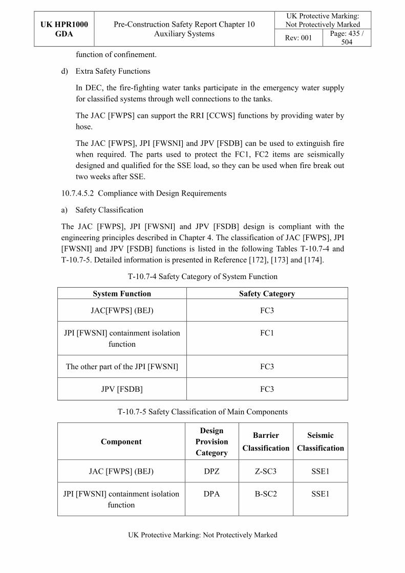
UK HPR1000
GDA
Pre-Construction Safety Report Chapter 10 Auxiliary Systems
UK Protective Marking: Not Protectively Marked
Rev: 001 Page: 435 /
504
UK Protective Marking: Not Protectively Marked
function of confinement.
d) Extra Safety Functions
In DEC, the fire-fighting water tanks participate in the emergency water supply for classified systems through well connections to the tanks.
The JAC [FWPS] can support the RRI [CCWS] functions by providing water by hose.
The JAC [FWPS], JPI [FWSNI] and JPV [FSDB] can be used to extinguish fire when required. The parts used to protect the FC1, FC2 items are seismically designed and qualified for the SSE load, so they can be used when fire break out two weeks after SSE.
10.7.4.5.2 Compliance with Design Requirements
a) Safety Classification
The JAC [FWPS], JPI [FWSNI] and JPV [FSDB] design is compliant with the engineering principles described in Chapter 4. The classification of JAC [FWPS], JPI [FWSNI] and JPV [FSDB] functions is listed in the following Tables T-10.7-4 and T-10.7-5. Detailed information is presented in Reference [172], [173] and [174].
T-10.7-4 Safety Category of System Function
System Function Safety Category
JAC[FWPS] (BEJ) FC3
JPI [FWSNI] containment isolation function
FC1
The other part of the JPI [FWSNI] FC3
JPV [FSDB] FC3
T-10.7-5 Safety Classification of Main Components
Component
Design
Provision
Category
Barrier
Classification
Seismic
Classification
JAC [FWPS] (BEJ) DPZ Z-SC3 SSE1
JPI [FWSNI] containment isolation function
DPA B-SC2 SSE1
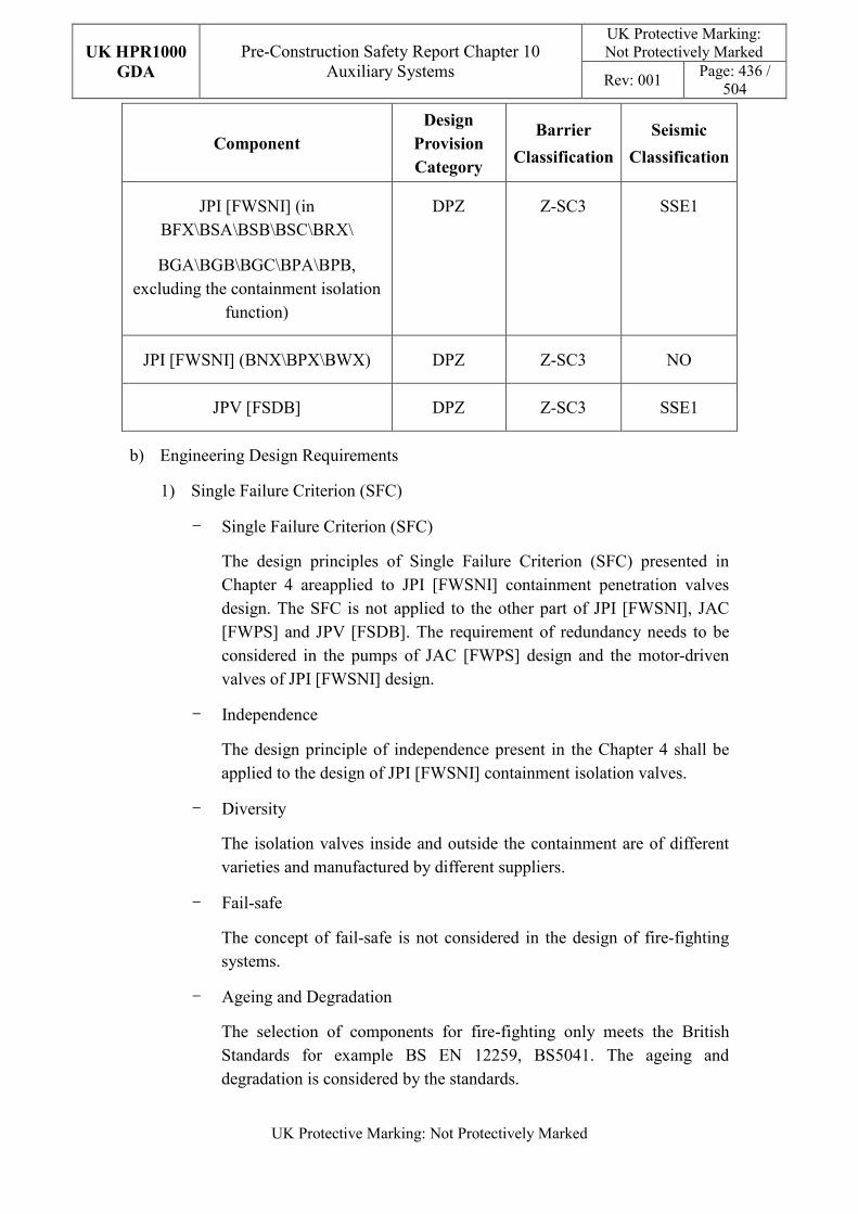
UK HPR1000
GDA
Pre-Construction Safety Report Chapter 10 Auxiliary Systems
UK Protective Marking: Not Protectively Marked
Rev: 001 Page: 436 /
504
UK Protective Marking: Not Protectively Marked
Component
Design
Provision
Category
Barrier
Classification
Seismic
Classification
JPI [FWSNI] (in BFX\BSA\BSB\BSC\BRX\
BGA\BGB\BGC\BPA\BPB, excluding the containment isolation
function)
DPZ Z-SC3 SSE1
JPI [FWSNI] (BNX\BPX\BWX) DPZ Z-SC3 NO
JPV [FSDB] DPZ Z-SC3 SSE1
b) Engineering Design Requirements
1) Single Failure Criterion (SFC)
- Single Failure Criterion (SFC)
The design principles of Single Failure Criterion (SFC) presented in Chapter 4 areapplied to JPI [FWSNI] containment penetration valves design. The SFC is not applied to the other part of JPI [FWSNI], JAC [FWPS] and JPV [FSDB]. The requirement of redundancy needs to be considered in the pumps of JAC [FWPS] design and the motor-driven valves of JPI [FWSNI] design.
- Independence
The design principle of independence present in the Chapter 4 shall be applied to the design of JPI [FWSNI] containment isolation valves.
- Diversity
The isolation valves inside and outside the containment are of different varieties and manufactured by different suppliers.
- Fail-safe
The concept of fail-safe is not considered in the design of fire-fighting systems.
- Ageing and Degradation
The selection of components for fire-fighting only meets the British Standards for example BS EN 12259, BS5041. The ageing and degradation is considered by the standards.
UK HPR1000
GDA
Pre-Construction Safety Report Chapter 10 Auxiliary Systems
UK Protective Marking: Not Protectively Marked
Rev: 001 Page: 437 /
504
UK Protective Marking: Not Protectively Marked
Some parts of fire-fighting systems which are difficult to replace, for example fire water tanks are designed for the 60 years. Some components will need to be replaced at the end of their individual designed life, for example pipes.
The layout design will take into consideration the need to remove old parts and to install replacements.
2) Human Factors
The design of the JAC [FWPS] pumps needs to avoid closed by human false, the local start and shut buttons are installed in a box for every pump.
The valves of open-type fixed fire extinguishing systems of JPI [FWSNI] and JPV [FSDB] need avoid opening by human falsely, therefore the operating procedures take this into consideration.
3) Autonomy
Not applicable.
4) Other Design Requirements
- Prevention of Harmful Interactions of Systems Important to Safety
Not applicable.
- Considerations Related to the Electrical Power Grid
Not applicable.
c) Equipment Qualification
The containment isolation valves of JPI [FWSNI] should be capable of operating under normal conditions and accident conditions, so the valves will be required to withstand the most penalised ambient environmental conditions.
The fire pumps, landing valves, sprinklers and other components specially designed for fire-fighting shall be certificated by the appropriate bodies for fire-fighting equipment.
All the seismically classified components are designed and qualified for SSE load.
d) Protection Design against Internal and External Hazards
1) Internal Hazard Protection
Fire protection measures are designed so that in the event of fire they are functional.
2) External Hazard Protection
UK HPR1000
GDA
Pre-Construction Safety Report Chapter 10 Auxiliary Systems
UK Protective Marking: Not Protectively Marked
Rev: 001 Page: 438 /
504
UK Protective Marking: Not Protectively Marked
The design of fire protection systems takes into account:
- Earthquakes
The JAC [FWPS] installed in BEJ, JPI [FWSNI] installed in BFX, BRX, BSX, BPA, BPB, BGA, BGB, BGC and JPV [FSDB] are seismic classified, so that they can be functional after SSE.
- The crash of an aircraft
The JAC [FWPS] installed in BEJ is designed to fulfil function after crash of a small plane. The JPI [FWSNI] and JPV [FSDB] are installed interior of NI, therefore impact of an additional aircraft is not considered.
- Extreme heat
The JAC [FWPS], JPI [FWSNI] and JPV [FSDB] pressurised parts are in doors and the temperature is conditioned by HVAC systems. The JAC [FWPS], JPI [FWSNI] and JPV [FSDB] pressurised parts are designed according to the highest temperature in the room.
- Extreme cold
The JAC [FWPS], JPI [FWSNI] and JPV [FSDB] pressurised parts are in doors and the temperature is conditioned by HVAC systems. The temperature in the room where the JAC [FWPS], JPI [FWSNI] and JPV [FSDB] are installed is above 0°C. In future if we find the temperature under 0°C in some seasons, dry systems for JPI [FWSNI] and JPV [FSDB] will be considered, and the pipes for the intake well and hydrants of JAC [FWPS] will be installed under frost line.
- Flooding
The rooms installed JAC [FWPS], JPI [FWSNI] and JPV [FSDB] are designed to defend external flooding according to Chapter 18. The parts of JAC [FWPS] outdoor flooded will not impact on its function. Therefore this does not need to be considered.
- Projectiles carried by the wind
The buildings installed JAC [FWPS], JPI [FWSNI] and JPV [FSDB] are designed to defend projectiles carried by the wind. Therefore no added measures considered for JAC [FWPS], JPI [FWSNI] and JPV [FSDB].
e) Commissioning
Commissioning will be carried out for the JAC [FWPS], JPI [FWSNI], JPV [FSDB] to valid their functionality. Documents related to the commissioning will
UK HPR1000
GDA
Pre-Construction Safety Report Chapter 10 Auxiliary Systems
UK Protective Marking: Not Protectively Marked
Rev: 001 Page: 439 /
504
UK Protective Marking: Not Protectively Marked
be delivered before GDA step 4. The methodology of the system commissioning programme is presented in Reference [29].
f) Examination, Maintenance, Inspection and Testing
1) Examination and Inspection
There is no equipment of associated with the JAC [FWPS], JPI [FWSNI], or JPV [FSDB] requiring in-service inspection except containment isolation valves.
The information of the JAC [FWPS], JPI [FWSNI] and JPV [FSDB] displayed on the Main Control Room (MCR) for the operator includes:
- Flow indicator status;
- Motor-driven valves position status;
- Fire pumps status;
- Water levels of the fire water tanks.
2) Maintenances
If damage is found by periodic tests or other inspection, the maintenance shall be performed immediately.
3) Periodic Tests
The fire-fighting equipment subject to periodic tests are the wet riser, the fixed systems for extinguishing fires and the fire-fighting water production and piping networks in conformance with the function requirements and operational experience.
The items in BRX require periodic testing during refuelling. In the other buildings, the tests will be carried out during normal times according to the
period advised by British standards,the authority having jurisdiction and the local fire and rescue services.
g) Decommissioning
Decommissioning considerations regarding the JAC [FWPS], JPI [FWSNI], JPV [FSDB] are taken into account during system design. The principles are given in reference SDM chapter 3.
h) Material Selection
The material of duct is stainless steel or carbon steel.
i) Special Thermal-hydraulic Phenomena
In order to ensure the functional reliability of the system and to prevent
UK HPR1000
GDA
Pre-Construction Safety Report Chapter 10 Auxiliary Systems
UK Protective Marking: Not Protectively Marked
Rev: 001 Page: 440 /
504
UK Protective Marking: Not Protectively Marked
challenges to performing the safety functions, phenomenon regarding water hammer shall be carefully considered in JAC [FWPS] design.
j) Insulation
Not applicable.
10.7.4.6 Simplified Diagrams
The simplified flow diagram of the fire-fighting systems as a whole is shown in Figure F-10.7-2. The detailed system functional diagrams are presented in Reference [175], [176] and [177].
10.7.5 Smoke Control System (DFL [SCS])
The Smoke Control System (DFL [SCS]) exhausts smoke in rooms with a fire and protects the protected rescue routes against smoke ingress during a fire. Information of the system is presented in the SDM chapter 2, Reference [179].
10.7.5.1 Safety Functional Requirements
10.7.5.1.1 Control of Reactivity
The DFL [SCS] does not contribute to this safety function.
10.7.5.1.2 Removal of Heat
The DFL [SCS] does not contribute to this safety function.
10.7.5.1.3 Confinement
The DFL [SCS] which forms an isolation barrier in the controlled area boundary contributes to the confinement of radioactive substances.
10.7.5.1.4 Extra Safety Functions
a) Supporting the Fundamental Safety Functions
The DFL [SCS] does not contribute to this safety function.
b) Prevent, Protect and Mitigate Hazards Impact
1) Fire
The DFL [SCS] must prevent smoke migration from affecting the classified equipment and safety of staff in the event of a fire.
2) External explosion
The DFL [SCS] must prevent external explosions from affecting the classified equipment.
UK HPR1000
GDA
Pre-Construction Safety Report Chapter 10 Auxiliary Systems
UK Protective Marking: Not Protectively Marked
Rev: 001 Page: 441 /
504
UK Protective Marking: Not Protectively Marked
10.7.5.2 Design Requirements
The general design requirements of the DFL [SCS] which need to be considered are shown in Sub-chapter 10.2.4, among which the following requirements are not applicable for the DFL [SCS]:
a) Autonomy in Respect of Operators
Not applicable, because the DFL [SCS] doesn’t contribute to the autonomy objective.
b) Autonomy in Respect of the Heat Sink
Not applicable, because the DFL [SCS] doesn’t provide a heat sink to the power plant.
c) Autonomy in Respect of Power Supply Systems
Not applicable, because the DFL [SCS] doesn’t provide a power supply to the power plant.
d) Prevention of Harmful Interactions of Systems Important to Safety
Not applicable, because the DFL [SCS] doesn’t have harmful interactions of systems important to safety.
e) Insulation
Not applicable, because the DFL [SCS] doesn’t have insulation design.
The substantiation analysis of DFL [SCS] system to other design requirements is shown in the Sub-chapter 10.7.5.5.2.
10.7.5.3 Design Bases
10.7.5.3.1 General Assumptions
An independent pressurised subsystem is provided for each protected rescue route.
The exhaust subsystem is divided according to the layout; each exhaust subsystem can contain multiple fire compartments.
10.7.5.3.2 Design Assumptions
a) Control of Reactivity
Not applicable. The DFL [SCS] does not contribute to the safety function of control of reactivity.
b) Removal of Heat
Not applicable. The DFL [SCS] does not contribute to the safety function of removal of heat.
UK HPR1000
GDA
Pre-Construction Safety Report Chapter 10 Auxiliary Systems
UK Protective Marking: Not Protectively Marked
Rev: 001 Page: 442 /
504
UK Protective Marking: Not Protectively Marked
c) Confinement
Isolation dampers which are installed in the controlled area boundary are normal level airtightness. For airtightness characteristics of the equipment see Table T-10.6-38.
d) Extra Safety Functions
1) Supporting the Fundamental Safety Functions
Not applicable. The DFL [SCS] does not contribute to supporting the fundamental safety functions.
2) Prevent, Protect and Mitigate Hazards Impact
- Fire
Not applicable. There is no quantitative safety-related design assumption associated with the DFL [SCS].
- External explosion
The parameters of external explosions which must be taken into consideration are given in Chapter 18 (External Hazards).
e) Other Assumptions
An overpressure of 20Pa to 80Pa is maintained for the protected rescue routes or compartments by the DFL [SCS] during a fire event.
The outside conditions to be taken into account for the DFL [SCS] are defined in Table T-10.6-42.
10.7.5.4 System Description and Operation
10.7.5.4.1 System Description
a) General System Description
The DFL [SCS] consists of two different subsystems:
1) Smoke Exhaust System
An exhaust system which mainly contains:
‒ A motorised isolation damper to isolate the building;
‒ A centrifugal extraction fan.
2) Pressurized System
A pressurized system which mainly contains:
‒ A motorised isolation damper;
UK HPR1000
GDA
Pre-Construction Safety Report Chapter 10 Auxiliary Systems
UK Protective Marking: Not Protectively Marked
Rev: 001 Page: 443 /
504
UK Protective Marking: Not Protectively Marked
‒ An axial air supply fan and a dedicated pressure measurement.
Detailed information of the systems is presented in the SDM, Reference [178]
b) Description of Main Equipment
1) Supply Air Fans
The fans are designed to provide the air supply for the protected rescue routes or compartments to maintain overpressure, and they are axial.
2) Smoke Exhaust Fans
The fans are designed to exhaust smoke within a fire room to create a negative pressure preventing smoke migration to adjacent rooms. The fans are a centrifugal and direct-coupled drive type.
3) Isolation Dampers
The isolation dampers can be isolated in the controlled areas of the buildings. The closing action provides the confinement function.
4) EPW Damper
The air intakes and outlets are protected against external explosions and tornados by EPW dampers installed in the classified buildings.
Detailed information of the equipment design is presented in the SDM chapter 4, Reference [178].
c) Description of Main Layout
Each subsystem of the DFL [SCS] is arranged independently. The smoke control subsystem is included in the BSX, BDX, and BNX. The pressurized air supply subsystem is included in the BSX, BDX, BNX, BPX, BWX, BEJ, BFX and BPA/BPB.
Detailed design information about the system layout is presented in the SDM, Reference [178].
d) Description of System Interface
1) Fire Alarm System (JDT [FAS])
The JDT [FAS] provides the fire signal to control the DFL [SCS].
2) Electrical Division of Safeguard Building Ventilation System (DVL [EDSBVS])
The DFL [SCS] uses the air intake and exhaust air plenums of the DVL [EDSBVS].
UK HPR1000
GDA
Pre-Construction Safety Report Chapter 10 Auxiliary Systems
UK Protective Marking: Not Protectively Marked
Rev: 001 Page: 444 /
504
UK Protective Marking: Not Protectively Marked
3) Main Control Room Air Conditioning System (DCL [MCRACS])
The DFL [SCS] uses the air intake plenum of the DCL [MCRACS].
4) Diesel Building Ventilation System (DVD [DBVS])
The DFL [SCS] uses the air intake and exhaust plenum of the DVD [DBVS].
Detailed information of the interface systems is presented in the SDM, Reference [178].
e) Description of Instrumentation and Control
Parameters, controlling and monitoring of the DFL [SCS] and displaying of the actuator are provided in the MCR.
Detailed information of the system I&C design is presented in the SDM, Reference [180].
10.7.5.4.2 System Operation
a) Plant Normal Conditions
The DFL [SCS] is not required to operate during plant normal operation. During plant operation and plant shutdown, the DFL [SCS] is in standby mode.
When the JDT [FAS]) detects fire in a fire compartment the corresponding pressurized subsystem of the DFL [SCS] starts automatically. The exhaust smoke subsystem of the DFL [SCS] for rooms with a fire is started manually by the operators.
b) Plant Accident Conditions
The DFL [SCS] has no requirement to operate in plant accident conditions.
Detailed information of the system operation is presented in the SDM, Reference [180].
10.7.5.5 Preliminary Design Substantiation
In this sub-chapter, the system design is demonstrated to satisfy the safety functional requirements presented in Sub-chapter 10.7.5.1 and the general design requirements stated in Sub-chapter 10.2.4. Review of the consistency of the system design against the newly developed principles is currently being undertaken.
10.7.5.5.1 Compliance with Safety Functional Requirements
a) Control of Reactivity
Not applicable.
b) Removal of Heat
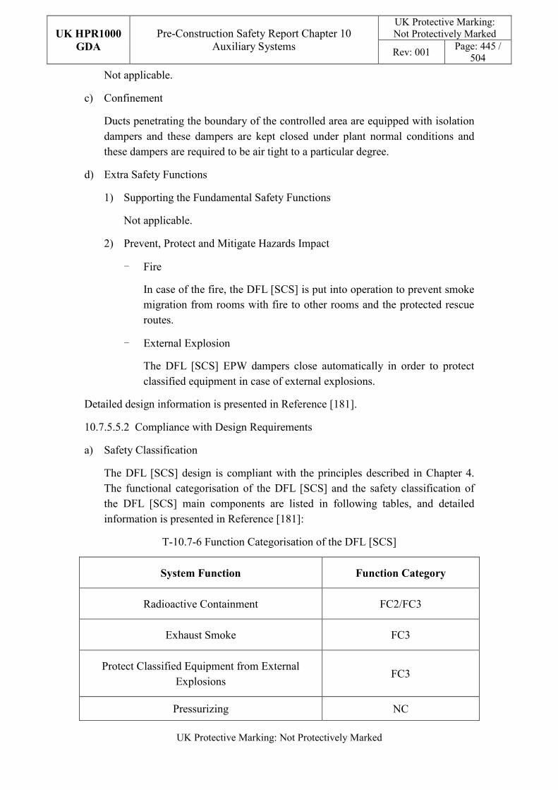
UK HPR1000
GDA
Pre-Construction Safety Report Chapter 10 Auxiliary Systems
UK Protective Marking: Not Protectively Marked
Rev: 001 Page: 445 /
504
UK Protective Marking: Not Protectively Marked
Not applicable.
c) Confinement
Ducts penetrating the boundary of the controlled area are equipped with isolation dampers and these dampers are kept closed under plant normal conditions and these dampers are required to be air tight to a particular degree.
d) Extra Safety Functions
1) Supporting the Fundamental Safety Functions
Not applicable.
2) Prevent, Protect and Mitigate Hazards Impact
- Fire
In case of the fire, the DFL [SCS] is put into operation to prevent smoke migration from rooms with fire to other rooms and the protected rescue routes.
- External Explosion
The DFL [SCS] EPW dampers close automatically in order to protect classified equipment in case of external explosions.
Detailed design information is presented in Reference [181].
10.7.5.5.2 Compliance with Design Requirements
a) Safety Classification
The DFL [SCS] design is compliant with the principles described in Chapter 4. The functional categorisation of the DFL [SCS] and the safety classification of the DFL [SCS] main components are listed in following tables, and detailed information is presented in Reference [181]:
T-10.7-6 Function Categorisation of the DFL [SCS]
System Function Function Category
Radioactive Containment FC2/FC3
Exhaust Smoke FC3
Protect Classified Equipment from External Explosions
FC3
Pressurizing NC
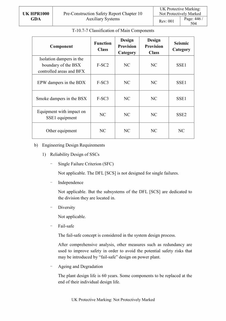
UK HPR1000
GDA
Pre-Construction Safety Report Chapter 10 Auxiliary Systems
UK Protective Marking: Not Protectively Marked
Rev: 001 Page: 446 /
504
UK Protective Marking: Not Protectively Marked
T-10.7-7 Classification of Main Components
Component Function
Class
Design
Provision
Category
Design
Provision
Class
Seismic
Category
Isolation dampers in the boundary of the BSX
controlled areas and BFX F-SC2 NC NC SSE1
EPW dampers in the BDX F-SC3 NC NC SSE1
Smoke dampers in the BSX F-SC3 NC NC SSE1
Equipment with impact on SSE1 equipment
NC NC NC SSE2
Other equipment NC NC NC NC
b) Engineering Design Requirements
1) Reliability Design of SSCs
- Single Failure Criterion (SFC)
Not applicable. The DFL [SCS] is not designed for single failures.
- Independence
Not applicable. But the subsystems of the DFL [SCS] are dedicated to the division they are located in.
- Diversity
Not applicable.
- Fail-safe
The fail-safe concept is considered in the system design process.
After comprehensive analysis, other measures such as redundancy are used to improve safety in order to avoid the potential safety risks that may be introduced by “fail-safe” design on power plant.
- Ageing and Degradation
The plant design life is 60 years. Some components to be replaced at the end of their individual design life.
UK HPR1000
GDA
Pre-Construction Safety Report Chapter 10 Auxiliary Systems
UK Protective Marking: Not Protectively Marked
Rev: 001 Page: 447 /
504
UK Protective Marking: Not Protectively Marked
2) Human Factors
The system design of DFL [SCS] does not require short term operator intervention, however there are operator actions during plant normal operation, the effect of which needs to be estimated. The DFL [SCS] is controlled and monitored in the main control room. It is designed to be convenient for operators to control.
3) Autonomy
Not applicable.
4) Other Design Requirements
- Prevention of Harmful Interactions of Systems Important to Safety
Not applicable.
- Considerations Related to the Electrical Power Grid
Not applicable.
c) Equipment Qualification
All the components of the DFL [SCS] required performing safety functions are capable of operating under both normal and accident conditions. As a result, the components can withstand the expected most adverse environmental conditions.
All the seismically classified components of the DFL [SCS] shall be capable of operating during and after the SSE. The components are seismically designed and qualified for the SSE loads.
Detailed equipment qualification classification of the system is presented in Reference [181]. Detailed information related to the system equipment qualification is presented in Reference [178].
d) Protection Design against Internal and External Hazards
The HVAC systems comply with the requirements of external and internal hazards stated in Sub-chapter 10.2.4, for ventilation system, the corresponding protection measures of earthquake and internal fire are described as below.
1) External hazards
- Earthquake
The Seismic Category 1 (SSE1) components are as follows:
- The supply air fans of DFL14 and DFL24 from controlled areas of Safeguard Building.
- External connection isolation dampers from controlled areas.
UK HPR1000
GDA
Pre-Construction Safety Report Chapter 10 Auxiliary Systems
UK Protective Marking: Not Protectively Marked
Rev: 001 Page: 448 /
504
UK Protective Marking: Not Protectively Marked
- The isolation dampers directly connected to the outside must be EPW resistant.
- The main control room smoke damper, smoke dampers and smoke exhaust fans in Safeguard Building.
- Smoke extraction isolation dampers in Diesel Building
The seismic class for the components having an impact on SSE1 equipment is Seismic Category 2 (SSE2).
The seismic class for the other DFL components is NC.
2) Internal hazards
- Internal Fire
The fire rating of the duct is same as the fire barrier when it passes through the barrier, if not; fire dampers are equipped in the duct. The fire rating of the duct is achieved by fireproof wrap.
Specific protection measures of other hazards are presented in Reference [182].
e) Commissioning
Commissioning and tests shall be carried out to validate the system’s functionality. The methodology of system commissioning programme design is presented in Reference [31]. Further detailed site specific arrangements for the UK HPR1000 commissioning activities will be presented during the nuclear site licencing phase in conjunction with the site licensee.
f) Examination, Inspection, Maintenance and Testing
1) Examination and Inspection
There is no equipment of the DFL [SCS] requiring in-service inspection.
The combined information of the DFL [SCS] displayed in the Main Control Room (MCR) for the operator includes:
- Smoke damper position status in the BSX;
- Inlet/outlet isolation damper position status in the controlled areas;
- Inlet/outlet isolation damper position status of the external explosion protection areas.
2) Maintenances
The maintenance of the DFL [SCS] can be performed during plant normal operation when the DFL [SCS] is not required.
UK HPR1000
GDA
Pre-Construction Safety Report Chapter 10 Auxiliary Systems
UK Protective Marking: Not Protectively Marked
Rev: 001 Page: 449 /
504
UK Protective Marking: Not Protectively Marked
3) Periodic Tests
For the UK HPR1000, the periodic test design is under development, the periodic test design method is presented in the Reference [32].
FC1, FC2 and FC3 equipment should be tested if they are not in continuous operation. Some equipment performing safety functions shall be subject to periodic testing, including correct operation of the dampers.
g) Decommissioning
Decommissioning considerations are taken into account of system design. The principles are given in SDM chapter 3, Reference [181].
h) Material Selection
The duct material is galvanised steel sheet or carbon steel.
The fire resistance duct is covered with fireproof material.
i) Insulation
Not applicable.
10.7.5.6 Simplified Diagrams
The simplified system diagram is presented in Figure F-10.7-3 and Figure F-10.7-4; the detailed system functional diagrams are presented in Reference [183].
10.7.6 ALARP Assessment
10.7.6.1 General Description
A preliminary ALARP analysis has been performed on the fire protection systems. The analysis is consistent with the arguments stated in the Sub-claim 3.3.6.SC10.3 of the route map presented in Appendix B:
Argument 3.3.6.SC10.3-1: The SSCs meet the requirements of the relevant design principles (generic and system specific) and therefore of relevant good practice;
The ALARP assessment is carried out following the ALARP methodology presented in Chapter 33, a specific ALARP demonstration report has been prepared, Reference [14].
10.7.6.2 Review of Design against RGP & OPEX
The RGP for SSCs design is identified, the suitable analysis against the applicable codes and standards identified for the SSCs design in ME area are carried out in Reference [13].
Preliminary ALARP analysis has been performed on the fire protection systems. The standards listed in Table T-10.7-1 are sources of relevant good practice for system and
UK HPR1000
GDA
Pre-Construction Safety Report Chapter 10 Auxiliary Systems
UK Protective Marking: Not Protectively Marked
Rev: 001 Page: 450 /
504
UK Protective Marking: Not Protectively Marked
component design. The system is designed in accordance with appropriate codes and standards;
At this stage there is no gap. However, review work will be continuously performed. When any new gap is identified, an ALARP analysis will be performed.
Materials comply with specifications defined in technical codes. A basic principle for the selection of materials is to use proven and successfully tested materials;
The fire protection system design is based on OPEX from China General Nuclear Power Corporation (CGN) and other PWR power plants operating in the world; at this stage, the wet risers are used to replace the fire hose station according to the OPEX from British power plants.
10.7.6.3 Insights from Risk Analysis
The risk analysis is currently being developed and a preliminary result was produced based on the current information no insight was received for the design of nuclear auxiliary systems from the current risk analysis. The analysis will keep being carried out as the GDA progresses.
10.7.6.4 Specific Review of Potential Improvements
In the process of gap identification, one gap is identified and becomes a design modification in the UK HPR1000. The wet risers are used to replace the fire hose stations.
10.7.6.5 ALARP Demonstration
A compliance analysis of the system design with respect to the UK HPR1000 general safety engineering principles is made in the system section of each sub-chapter. The analysis shows that the design of the SSCs meets relevant requirements and no gaps have been identified. A systematic review will be carried out on the system design to ensure that no new gaps are identified between the newly developed requirements and the design. Any potential enhancements identified during this review will be taken into account in the future design development.
In summary, the ALARP analysis and demonstration work is currently being carried out. A preliminary ALARP demonstration topic report to present the current analysis results as well as the arrangement for future ALARP analysis work is presented in Reference [14].
10.7.7 Concluding Remarks
This chapter provides an introduction of the design information of the fire protection systems in the UK HPR1000 nuclear power plant and demonstrates that the systems satisfy the performance requirements.
As various technical areas are currently under development, a systematic review will
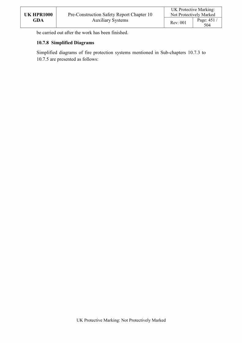
UK HPR1000
GDA
Pre-Construction Safety Report Chapter 10 Auxiliary Systems
UK Protective Marking: Not Protectively Marked
Rev: 001 Page: 451 /
504
UK Protective Marking: Not Protectively Marked
be carried out after the work has been finished.
10.7.8 Simplified Diagrams
Simplified diagrams of fire protection systems mentioned in Sub-chapters 10.7.3 to 10.7.5 are presented as follows:
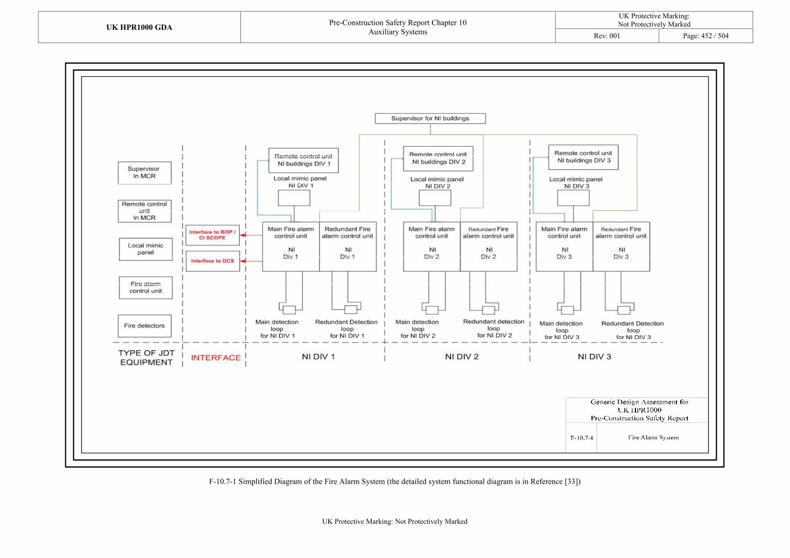
UK HPR1000 GDA Pre-Construction Safety Report Chapter 10
Auxiliary Systems
UK Protective Marking: Not Protectively Marked
Rev: 001 Page: 452 / 504
UK Protective Marking: Not Protectively Marked
F-10.7-1 Simplified Diagram of the Fire Alarm System (the detailed system functional diagram is in Reference [33])
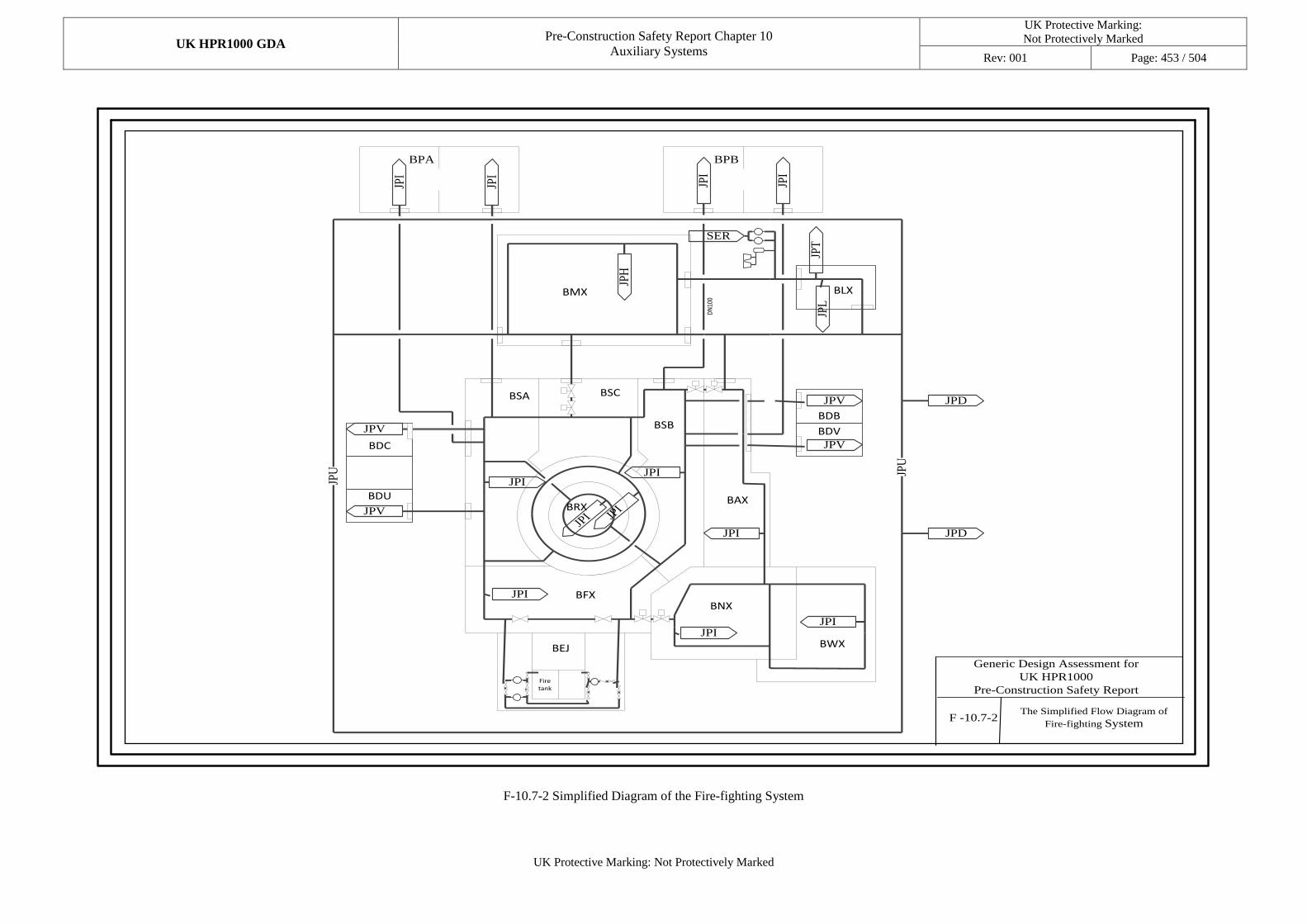
UK HPR1000 GDA Pre-Construction Safety Report Chapter 10
Auxiliary Systems
UK Protective Marking:
Not Protectively Marked
Rev: 001 Page: 453 / 504
UK Protective Marking: Not Protectively Marked
JPI
JPI
JPI
JPI
JPV
JPV
JPV
JPV
JPI
JPU
JPD
JPD
JPT
JPL
JPI
JPI
SER
JPI
JPI
JPI
JPI JPU
JPI
JPH
BPA BPB
BLX
DN
100
BMX
BDC
BDU
BSA BSC
BRX
BSB
BAX
BDB
BDV
BFXBNX
BEJ
Fire tank
BWX
F -10.7-2The Simplified Flow Diagram of
Fire-fighting System
Generic Design Assessment for
UK HPR1000
Pre-Construction Safety Report
F-10.7-2 Simplified Diagram of the Fire-fighting System
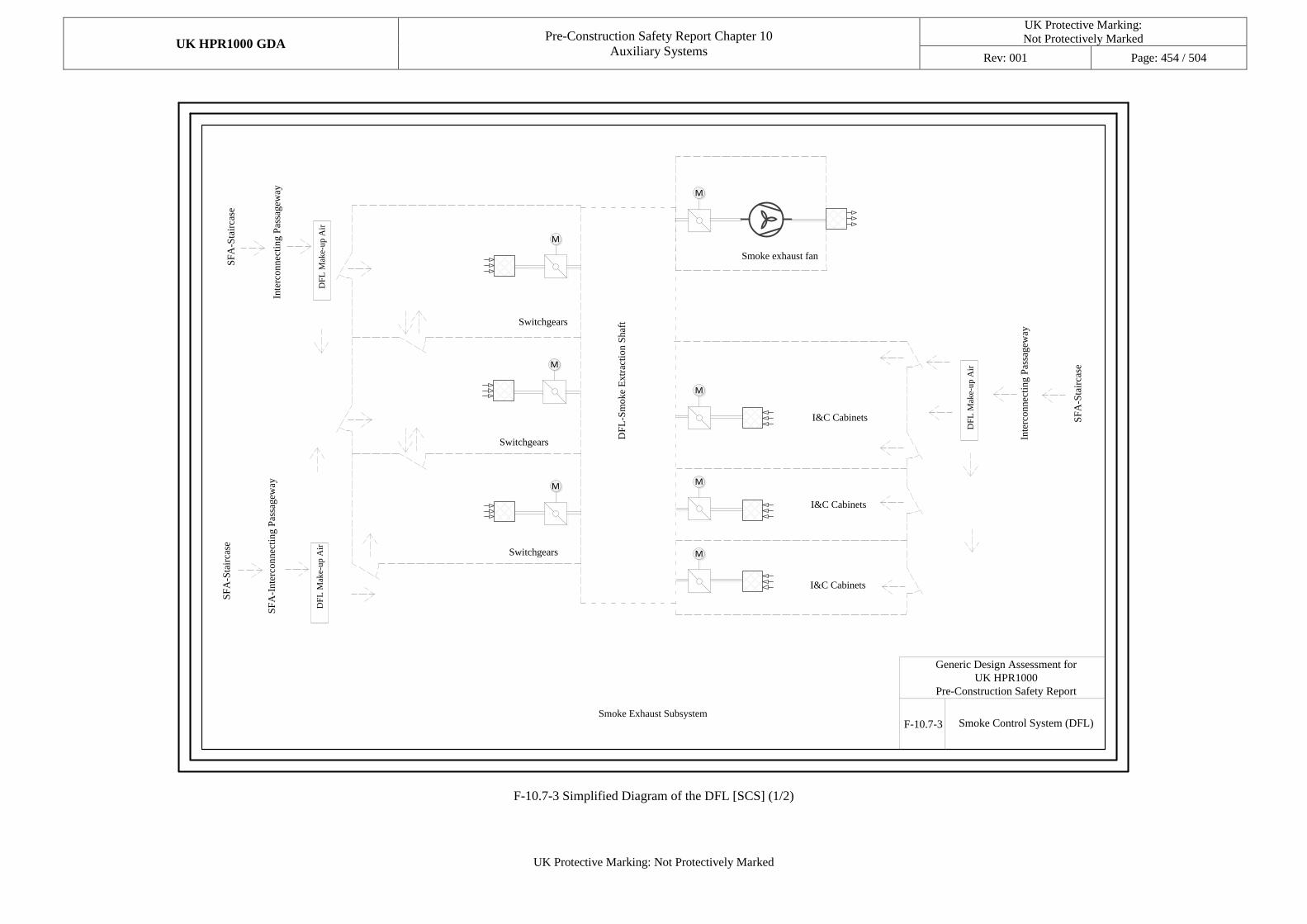
UK HPR1000 GDA Pre-Construction Safety Report Chapter 10
Auxiliary Systems
UK Protective Marking:
Not Protectively Marked
Rev: 001 Page: 454 / 504
UK Protective Marking: Not Protectively Marked
Switchgears
DF
L-S
moke
Extr
acti
on S
haf
t
I&C Cabinets
SF
A-S
tair
case
Inte
rconnec
ting P
assa
gew
ay
DF
L M
ake-
up A
ir
Smoke exhaust fan
Smoke Exhaust Subsystem
Switchgears
Switchgears
I&C Cabinets
I&C Cabinets
SF
A-S
tair
case
SF
A-I
nte
rconnec
ting P
assa
gew
ay
DF
L M
ake-
up A
ir
DF
L M
ake-
up A
ir
Inte
rconnec
ting P
assa
gew
ay
SF
A-S
tair
case
Smoke Control System (DFL)F-10.7-3
Generic Design Assessment for
UK HPR1000
Pre-Construction Safety Report
M
M
M
M
M
M
M
F-10.7-3 Simplified Diagram of the DFL [SCS] (1/2)
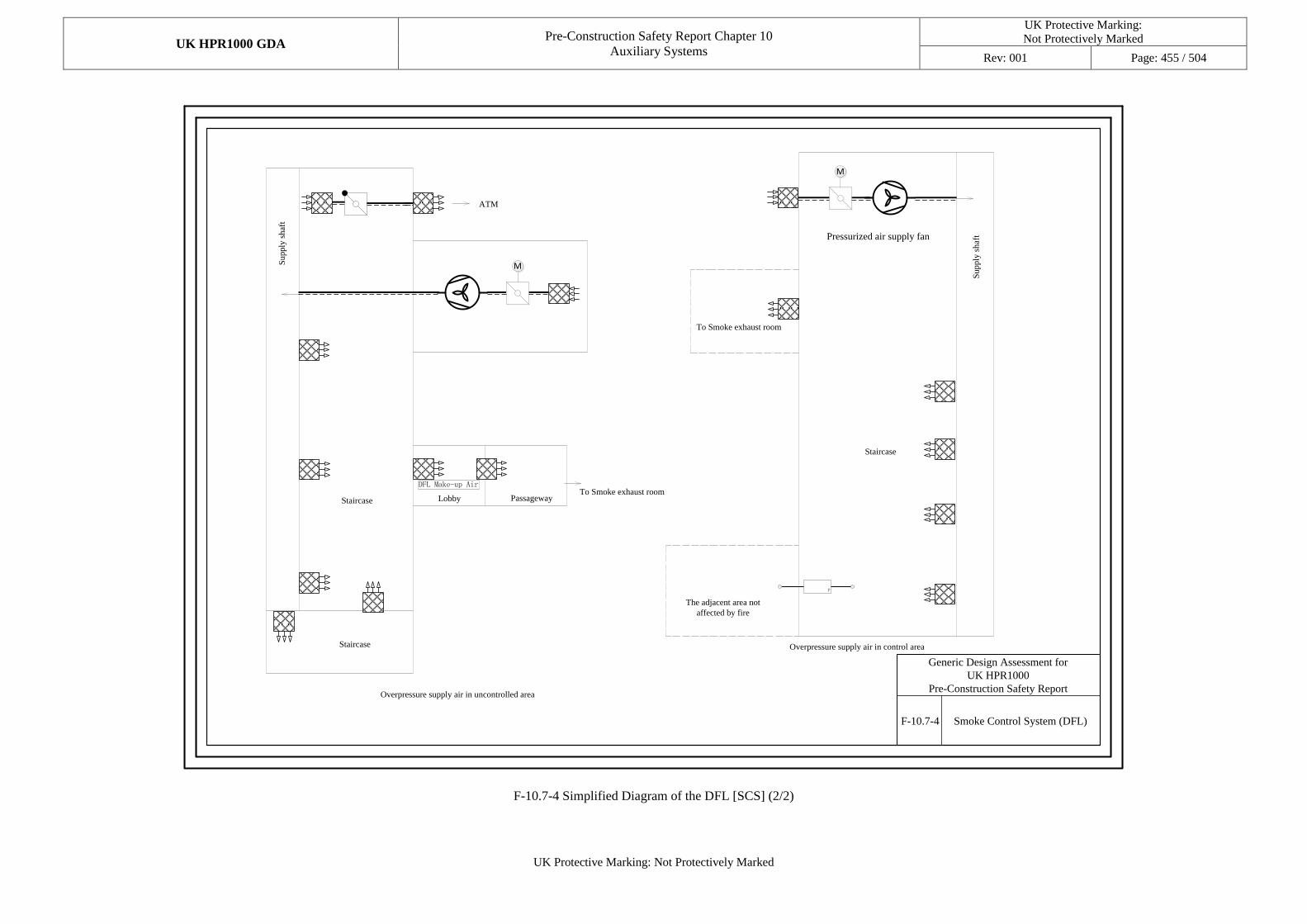
UK HPR1000 GDA Pre-Construction Safety Report Chapter 10
Auxiliary Systems
UK Protective Marking:
Not Protectively Marked
Rev: 001 Page: 455 / 504
UK Protective Marking: Not Protectively Marked
F-10.7-4 Smoke Control System (DFL)
Generic Design Assessment for
UK HPR1000
Pre-Construction Safety Report
ATM
Su
pp
ly s
haf
t
StaircaseTo Smoke exhaust room
Overpressure supply air in uncontrolled area
Overpressure supply air in control area
To Smoke exhaust room
Su
pp
ly s
haf
t
Staircase
Lobby Passageway
Staircase
The adjacent area not
affected by fire
P
Pressurized air supply fan
M
M
F-10.7-4 Simplified Diagram of the DFL [SCS] (2/2)
UK HPR1000
GDA
Pre-Construction Safety Report Chapter 10 Auxiliary Systems
UK Protective Marking: Not Protectively Marked
Rev: 001 Page: 456 /
504
UK Protective Marking: Not Protectively Marked
10.8 Diesel Generators
The main objective of Sub-chapter 10.8 is to present the design information of the auxiliary systems and mechanical equipment for the Diesel Generator (DG) in the UK HPR1000 nuclear power plant, including:
a) Auxiliary systems of the Emergency Diesel Generator (EDG).
b) Auxiliary systems of the SBO Diesel Generator (SBO DG).
10.8.1 Sub-chapter Structure
The general structure of Sub-chapter 10.8 is presented as below:
a) Sub-chapter 10.8.1 introduces the objectives, structures and the interfaces.
b) Sub-chapter 10.8.2 presents the relative codes and standards, which are intended to be used in the UK HPR1000, with respect to the auxiliary systems of the DGs and their components design.
c) Sub-chapter 10.8.3 presents the design information of the EDGs and auxiliary systems.
d) Sub-chapter 10.8.4 presents the design information of the SBO DGs and auxiliary systems.
e) Sub-chapter 10.8.5 presents the ALARP assessment.
f) Sub-chapter 10.8.6 presents the concluding remarks.
g) Sub-chapter 10.8.7 presents the simplified diagrams.
10.8.2 Applicable Codes and Standards
The identification of applicable codes and standards in Sub-chapter 10.8 is compliant with the selection principles and the selection process stated in PCSR Chapter 4 and Reference [12].
Wherever possible, the selected codes and standards applied for the engineering substantiation are:
a) Commensurate with the categorisation of safety functions and classification of the SSC.
b) Internationally recognised in nuclear industry.
c) The latest or currently applicable approved standards.
Based on the selection principles and the selection process, the applicable codes and standards which are applied in Mechanical Engineering (ME) design are identified and evaluated. During GDA step 2, the suitable analysis against the applicable codes and standards identified for the SSC design in the ME area are carried out in
UK HPR1000
GDA
Pre-Construction Safety Report Chapter 10 Auxiliary Systems
UK Protective Marking: Not Protectively Marked
Rev: 001 Page: 457 /
504
UK Protective Marking: Not Protectively Marked
Reference [13]. In step 3, a compliance analysis is carried out and presented in Reference [14]. Main applicable codes and standards for the DGs and auxiliary systems are presented in T-10.8-1, which are identified to be the preliminary RGP.
T-10.8-1 Applicable Codes and Standards in Sub-chapter 10.8
Codes and Standards Number Title
IEEE 387, 2017 Diesel-generator Units Applied as Standby Power Supplies for Nuclear Power Generating Stations
RCC-M, 2007 Design and Construction Rules for Mechanical Components of PWR Nuclear Islands
BS 2869, 2017 Fuel Oils for Agricultural, Domestic and Industrial Engines and Boilers Specification
BS ISO 8528 (series) Reciprocating Internal Combustion Engine Driven Alternating Current Generating Sets (Series)
The application of the above standards in the system is described briefly below.
a) The standard, IEEE 387, provides the principal design criteria, the design features, testing, and qualification requirements for the individual DG units that enable them to meet their functional requirements as a part of the standby power supply under the accidental conditions of the nuclear power plant (NPP).
b) The standard, RCC-M, is applicable to the components performing the safety functions, including the piping, pumps, valves and vessels.
c) The BS 2869 is a local standard in United Kingdom, which provides the specification of fuel oils applicable to DGs. The fuel classes and chemical properties are specified in this standard.
d) The standards, BS ISO 8528 (series), are exclusive for DGs, which provide many technical specifications for the procurement of DGs in nuclear power plants, such as the rating, performance, test methods, control gear and switchgear, and measurement of mechanical vibrations.
UK HPR1000
GDA
Pre-Construction Safety Report Chapter 10 Auxiliary Systems
UK Protective Marking: Not Protectively Marked
Rev: 001 Page: 458 /
504
UK Protective Marking: Not Protectively Marked
10.8.3 Emergency Diesel Generator
10.8.3.1 Safety Functional Requirements
The requirements of the fundamental safety functions on the EDG design for the UK HPR1000 are identified as below.
10.8.3.1.1 Control of Reactivity
Not applicable. The auxiliary systems of EDGs do not contribute directly to the control of reactivity.
10.8.3.1.2 Removal of Heat
Not applicable. The auxiliary systems of EDGs do not contribute directly to this safety function.
10.8.3.1.3 Confinement
Not applicable. The auxiliary systems of EDGs do not contribute directly to the confinement of radioactive substances.
10.8.3.1.4 Extra Safety Functions
The detailed functional requirements of EDGs are shown in Sub-chapter 9.6.4.
10.8.3.2 Design Requirements
The general design requirements of the EDG auxiliary systems which need to be considered are shown in Sub-chapter 10.2.4, although some requirements are not fully applicable.
10.8.3.3 Design Bases
10.8.3.3.1 General Assumption
The site specific parameters are the input data for the design of the auxiliaries of the EDGs. The fuel oil and cooling water are selected according the environment temperature, ensuring that the mediums are not frozen even in extreme low temperature conditions. The applicable auxiliary equipment is designed and purchased to ensure their performance and reliability in the extreme site conditions.
10.8.3.3.2 Design Assumption
a) Control of Reactivity
Not applicable. The auxiliary systems of EDGs do not contribute directly to the control of reactivity.
b) Removal of Heat
Not applicable. The auxiliary systems of EDGs do not contribute directly to this
UK HPR1000
GDA
Pre-Construction Safety Report Chapter 10 Auxiliary Systems
UK Protective Marking: Not Protectively Marked
Rev: 001 Page: 459 /
504
UK Protective Marking: Not Protectively Marked
safety function.
c) Confinement
Not applicable. The auxiliary systems of EDGs do not contribute directly to the confinement of radioactive substances.
d) Extra Safety Functions
The rated power of the EDGs is designed according to the operational requirements of various systems in accidental conditions. The sizes and parameters of auxiliary equipment shall match with the diesel engine. The preheating system and the pre-lubricating system must provide the required conditions to ensure diesel engine start-up, and they must be shut down after the EDG has been started up.
10.8.3.4 System Description and Operation
10.8.3.4.1 System Description
The EDG set is composed of five auxiliary systems, including the fuel oil system, lubrication oil system, coolant system, compressed air start-up system, and the air intake and exhaust system. The EDG performs FC1 safety functions. Its building, diesel generator, relevant auxiliary equipment and cable channel is designed to withstand a SSE.
a) Fuel Oil System
The fuel oil system of the EDG set performs the function of supplying fuel oil to the EDG set. The main equipment of the fuel oil system includes:
1) Main fuel storage tank.
2) Daily oil tank.
3) Fuel delivery pumps.
4) Fuel booster pump.
5) Engine-driven fuel oil pump.
Each EDG set is equipped with an independent fuel storage tank and a daily oil tank. There are two delivery pumps with 100% capacity between the main fuel storage tank and daily oil tank.
The capacity of the main fuel storage tank of the EDG set can store enough fuel oil to enable the related EDG set to keep on running for 7 consecutive days under the maximum power output after an accident scenario accompanied by a loss of offsite power. The daily oil tank is installed above the EDG to ensure feeding of fuel oil to the EDG by gravity, and it has sufficient capacity for 2-hour continuous
UK HPR1000
GDA
Pre-Construction Safety Report Chapter 10 Auxiliary Systems
UK Protective Marking: Not Protectively Marked
Rev: 001 Page: 460 /
504
UK Protective Marking: Not Protectively Marked
operation of the EDG set at 110% rated power.
The main fuel storage tanks, daily fuel tanks, fuel delivery pumps and main system pipelines in the diesel generator buildings meet the seismic design requirements of SSE1.
The activated equipment of class F-SC1 is designed to meet the requirement that their operational functions can be maintained during and after an earthquake. The non-activated equipment of class F-SC1 is designed to meet the requirement that their integrity can be maintained after an earthquake.
b) Lubrication Oil System
This system is also referred to as the lube oil system. The lubrication oil system of the EDG set mainly consists of the following equipment:
1) Engine-driven lubricating oil pump.
2) Pre-lubricating oil pump.
3) Lubrication oil/water heat exchangers.
4) Lubrication oil filter.
5) Oil and gas separator.
During the operation of the EDG set, the main lubricating oil pump driven by the diesel engine is able to provide sufficient lubricating oil to the main bearing, crankpin, camshaft bearing and other wearing parts which need to be lubricated.
Each EDG set is equipped with a pre-lubricating system. It consists of an electrical pre-lubricating oil pump and a lubrication oil/water heat exchanger. When the EDG set is in the standby state, the pre-lubricating oil pump sends lubricating oil to the components of the EDG which need lubrication to ensure the reliability of start-up.
c) Coolant System
Each EDG set is equipped with two cooling circulation systems, including diesel cooling system and admission air cooling system. The systems are designed to meet the requirements of SSE1.
1) Diesel cooling system
This system is also referred to as the high temperature cooling water system. Each EDG set is equipped with its own independent closed cycle diesel cooling system to remove heat from the crankcase and cylinder liner.
The diesel cooling system includes the following equipment:
- Engine-driven circulating pump.
UK HPR1000
GDA
Pre-Construction Safety Report Chapter 10 Auxiliary Systems
UK Protective Marking: Not Protectively Marked
Rev: 001 Page: 461 /
504
UK Protective Marking: Not Protectively Marked
- Air-cooled heat radiators.
- Expansion tank.
- Electrical circulating pump.
- Lubrication oil/water heat exchanger.
- Electrical heater.
Each EDG set is equipped with a preheating system, to ensure that the EDG set can start within 15 seconds after receiving the start-up signal. When the EDG is on standby, cooling water, after being heated by the electrical heater, is forced to flow towards the end of the EDG by the electrical circulating pump. It supplies water to the crankcase and cylinder liner for preheating. The preheating system runs automatically when the EDG set is on standby. When the EDG set starts, the preheating system stops operation.
2) Admission air cooling system
This system is also referred to as the low temperature cooling water system. The admission air cooling system includes the following equipment:
- Engine-driven circulating pump.
- Air-cooled heat radiator.
- Expansion tank.
- Lubrication oil/water heat exchanger.
- Intermediate cooler.
When the EDG is in operation, the engine-driven circulating pump can supply water to the intermediate cooler and lubrication oil/water heat exchanger for cooling. The heat from the EDG set carried by the cooling water system is discharged into the atmosphere through the air-cooled heat radiators.
d) Compressed Air Start-up System
Each EDG set is equipped with two independent air start-up systems which can start the EDG respectively.
When one start-up system of the EDG fails, the EDG set can be started by the other start-up system. When the EDG set has received the start-up signal, the two main start-up air valves actuate simultaneously in order to start the EDG set.
Each start-up system is composed of an air storage tank. According to the pressure of the air storage tank, the compressor starts up and shuts down automatically. The capacity of the air storage tank is sized to allow five successful start-ups without refilling from the air compressor.
UK HPR1000
GDA
Pre-Construction Safety Report Chapter 10 Auxiliary Systems
UK Protective Marking: Not Protectively Marked
Rev: 001 Page: 462 /
504
UK Protective Marking: Not Protectively Marked
In order to protect the EDG set, the compressed air start-up system is equipped with an over-speed protection tank. When the speed of the EDG reaches 112% of the rated speed, the over-speed protection tank provides high-pressure air to the EDG, cuts off the fuel supply, and achieves the purpose of shutdown.
e) Air Intake and Exhaust System
Each EDG set is equipped with the following equipment:
1) Air intake filter.
2) Exhaust silencer.
3) Turbocharger.
4) Intermediate cooler.
The air intake and exhaust system of the EDG set supplies air to the diesel engine, which is needed for combustion and the gaseous waste product is discharged into the atmosphere.
The EDG takes in combustion air outside the diesel building through pipelines and ducts. After being filtered, the combustion air is compressed in the EDG with its temperature rising. After being cooled in the intermediate cooler, the compressed air enters the cylinders for burning. Gaseous waste after burning is dumped from the cylinders. It enters the turbocharger through the vent pipe of the EDG to propel the turbine. After that, it enters the vent pipe and finally the atmosphere through the exhaust silencer.
The exhaust pipe is equipped with insulation material to meet the requirements of high temperature resistance, and the temperature at the end of the exhaust pipe is controlled to prevent condensation and corrosion of the pipe.
f) Description of Main Equipment
The main mechanical equipment includes the diesel engine and auxiliary equipment.
The diesel engine is a four-stroke, water cooled, V-type cylinder, supercharged mechanical equipment driving the generator with a rated electrical power of approximately {**** **}. The specific requirements about the EDG and the descriptions of main equipment are presented in the SDM, Reference [184] and [185].
g) Description of Main Layout
The three EDGs are located in three separate emergency diesel generator buildings, which are named BDA, BDB and BDC. For each building, there are eight levels, including two underground levels and six over-ground levels.
UK HPR1000
GDA
Pre-Construction Safety Report Chapter 10 Auxiliary Systems
UK Protective Marking: Not Protectively Marked
Rev: 001 Page: 463 /
504
UK Protective Marking: Not Protectively Marked
The underground levels contain the main oil storage tank, fuel delivery pumps, pre-lubricating oil pumps, plate heat exchangers, electrical heater, and high temperature water preheating pumps.
The ground level contains the diesel generator, compressors, and air storage tanks.
The daily oil tank and air intake filter are located on the third over-ground floor. The exhaust silencer, expansion tanks, and air-cooled heat radiators are installed on the fifth over-ground floor.
The relevant layout description is presented in the SDM, Reference [186].
10.8.3.4.2 System Operation
a) Plant Normal Conditions
In the normal conditions of the power plant, the EDG is in standby state. The engine can be pre-lubricated by the lubrication oil system, and pre-heated by the coolant system. The auxiliary systems are always available to ensure the start-up of the EDG at any time.
b) Plant Accidental Conditions
In the event of LOOP, the EDG can be started up immediately, and the auxiliary systems can ensure the stable operation of the diesel engine. When the off-site power supply is recovered, the EDG can only be stopped manually. The auxiliary systems of EDG enable the engine to run continuously for 7 days at the rated power.
10.8.3.5 Preliminary Design Substantiation
10.8.3.5.1 Compliance with Safety Functional Requirements
The EDG and its auxiliary systems do not directly contribute to fundamental safety functions. For the extra safety functional requirements, the substantiation is presented in PCSR Sub-chapter 9.6.4 in terms of electrical engineering, and in PCSR Sub-chapter 10.8.3 in terms of mechanical engineering.
10.8.3.5.2 Compliance with Design Requirements
a) Safety Classification
The EDGs perform FC1 safety functions.
With regards to the main components of the auxiliary systems, the detailed information is presented in the SDM, Reference [184].
b) Redundancy and Single Failure Criterion
The design principles of the SFC presented in PCSR Chapter 4 are applicable to
UK HPR1000
GDA
Pre-Construction Safety Report Chapter 10 Auxiliary Systems
UK Protective Marking: Not Protectively Marked
Rev: 001 Page: 464 /
504
UK Protective Marking: Not Protectively Marked
the EDGs and auxiliary systems, therefore, three EDG sets are designed for a single nuclear reactor and the EDG sets are redundant.
c) Independence
All DG buildings are physically separated and the three EDGs are independent from one another.
d) Diversity
All auxiliary systems of the three EDGs are designed in the same way and there is no diversity for the EDGs and auxiliary systems.
e) Fail-safe
The concept of fail-safe is considered in the design of the EDG auxiliary systems. For example, the pneumatic valves in the compressed air system are in the shut-off state if the valves fail.
f) Ageing and Degradation
According to PCSR Chapter 2, the operational design life of the UK HPR1000 is 60 years. The main components of the systems are designed for the 60 year plant operation.
The ageing effect concerning individual components has been taken into consideration in the system design. A procedure of periodic maintenance is developed and implemented to prevent ageing and degradation. The periodic tests, preventive maintenance and replacement can ensure the system reliability.
g) Human Factors
The concept of human factors is taken into consideration in the system design. In the normal condition of the power plant, the EDGs are in standby state and no human intervention is needed. During commissioning or maintenance activities, the requirements and procedures about human factors are carried out and implemented.
h) Autonomy
The EDG can produce power autonomously for 7 days. For example, the main fuel oil storage tank has the capability to sustain 7 days of continuous operation of the EDG at the rated power.
i) Equipment Qualification
All the safety classified components in the EDG auxiliary systems, are qualified in accordance with the requirements described in PCSR Chapter 4.
The EDG performs class FC1 safety functions. For the related components, the
UK HPR1000
GDA
Pre-Construction Safety Report Chapter 10 Auxiliary Systems
UK Protective Marking: Not Protectively Marked
Rev: 001 Page: 465 /
504
UK Protective Marking: Not Protectively Marked
item classification is F-SC1 and the seismic category is SSE1.
All the seismically classified components operate during and after the SSE. The components are seismically designed and qualified for the SSE loads.
j) Protection against Internal and External Hazards
Internal Hazards: The safety critical components in the EDG buildings are separated physically or by leaving space to satisfy the internal hazard protection requirements.
External Hazards: The seismic category of the FC1 components is SSE1 and these components are arranged in the EDG buildings which are capable to of withstanding external hazards such as earthquakes, aircraft impact, external flooding, external explosions and tornados.
k) Commissioning and Tests
1) Initial testing of the EDGs and auxiliary equipment before delivery to site (for example Factory Acceptance Tests) is undertaken in accordance with procurement, manufacturing and commissioning quality arrangements.
2) Following acceptance of the equipment by the commissioning organisation, a structured, systematic and progressive test programme, which includes all the activities required for confirmation and demonstration of the EDG operational and safety functional performance requirements, are implemented. The test programme mainly includes start-up test, routine inspection, and periodic tests. The routine inspection is implemented to ensure the normal operation of the preheating and pre-lubricating systems. The start-up test and periodic tests are implemented to ensure the function of the EDGs.
l) Examination, Maintenance, Inspection and Testing
The EDGs are designed to permit examination, maintenance, inspection and testing, which is in accordance with the requirements from the maintenance strategy of the plant, equipment technical specification, equipment operating and maintenance manual, operation experience, etc. The total number of starts, operating hours at zero power and operating hours in loaded conditions are recorded to perform the preventive maintenance of the EDGs.
1) Daily examination of the EDGs and important parameters of the auxiliary systems are performed.
2) Periodic inspection and preventive maintenance is scheduled, which is mainly performed during the Reactor Completely Discharge (RCD) mode.
3) The availability of the system and equipment is demonstrated by periodic tests, including the start-up test, load carrying test, power supply switchover
UK HPR1000
GDA
Pre-Construction Safety Report Chapter 10 Auxiliary Systems
UK Protective Marking: Not Protectively Marked
Rev: 001 Page: 466 /
504
UK Protective Marking: Not Protectively Marked
test, etc. The typical frequency and items being periodically tested are:
- Every two months: Start up the engine, load the EDG to a lower power and stabilise it for two hours.
- Every eighteen months: Test the full power operation for 2 hours and sample the engine lube oil and cooling water.
The detailed EMIT description is presented in SDM, Reference [187].
10.8.3.6 Simplified Diagrams
The simplified system diagram is presented in Figure F-10.8-1.
10.8.4 SBO Diesel Generator
10.8.4.1 Safety Functional Requirements
The requirements of the fundamental safety functions on the SBO design for the UK HPR1000 are identified as below.
10.8.4.1.1 Control of Reactivity
Not applicable. The auxiliary systems of SBO DGs do not contribute directly to the control of reactivity.
10.8.4.1.2 Removal of Heat
Not applicable. The auxiliary systems of SBO DGs do not contribute directly to this safety function.
10.8.4.1.3 Confinement
Not applicable. The auxiliary systems of SBO DGs do not contribute directly to the confinement of radioactive substances.
10.8.4.1.4 Extra Safety Functions
The detailed functional requirements of SBO DGs are shown in PCSR Sub-chapter 9.6.5.
10.8.4.2 Design Requirements
The general design requirements of the SBO DG auxiliary systems which need to be considered are shown in Sub-chapter 10.2.4, although some requirements are not fully applicable.
10.8.4.3 Design Bases
10.8.4.3.1 General Assumption
The site specific parameters are the input data for the design of the auxiliaries of the SBO DGs. The fuel, oil and the cooling water are selected according the environment
UK HPR1000
GDA
Pre-Construction Safety Report Chapter 10 Auxiliary Systems
UK Protective Marking: Not Protectively Marked
Rev: 001 Page: 467 /
504
UK Protective Marking: Not Protectively Marked
temperature, ensuring that the mediums are not frozen even in the extreme low temperature. The applicable auxiliary equipment is designed and purchased to ensure their performances and reliabilities in the extreme site condition.
10.8.4.3.2 Design Assumption
a) Control of Reactivity
Not applicable. The auxiliary systems of SBO DGs do not contribute directly to the control of reactivity.
b) Removal of Heat
Not applicable. The auxiliary systems of SBO DGs do not contribute directly to this safety function.
c) Confinement
Not applicable. The auxiliary systems of SBO DGs do not contribute directly to the confinement of radioactive substances.
d) Extra Safety Functions
According to the operation requirements of various systems in accident conditions, the rated powers of SBO DGs are designed, and the sizes and parameters of auxiliary equipment is matched with the diesel engine. The preheating system and the pre-lubricating system can provide the required condition to ensure the diesel engine start-up, and they are shut down after the SBO DG has been started up.
10.8.4.4 System Description and Operation
The SBO DG set is composed of five auxiliary systems, including the fuel oil system, lubrication oil system, coolant system, compressed air start-up system, and the air intake and exhaust system. The SBO DG performs FC2 safety functions. Its building, diesel generator, relevant auxiliary equipment and cable channel is designed to withstand a SSE.
10.8.4.4.1 System Description
a) Fuel Oil System
The fuel system of the SBO DG set performs the function of supplying fuel to the SBO DG. The main equipment of the fuel system includes:
1) Main fuel storage tank.
2) Daily oil tank.
3) Fuel delivery pumps.
UK HPR1000
GDA
Pre-Construction Safety Report Chapter 10 Auxiliary Systems
UK Protective Marking: Not Protectively Marked
Rev: 001 Page: 468 /
504
UK Protective Marking: Not Protectively Marked
4) Fuel booster pump.
5) Engine-driven fuel oil pump.
Each SBO DG set is equipped with an independent fuel storage tank and a daily oil tank. There are two delivery pumps with 100% capacity between the main fuel storage tank and daily oil tank.
The main fuel storage tank of the SBO DG set can store enough fuel to enable the related SBO DG to remain running for 3 days at maximum power after an accident accompanied by a SBO. The fuel oil daily tank is installed above the SBO DG to ensure feeding fuel oil to the SBO DG by gravity, and it has sufficient capacity for 2-hour continuous operation of the SBO DG set at 110% rated power.
b) Lubrication Oil System
This system is also referred to as the lube oil system. The lubrication oil system of every SBO DG mainly consists of the following equipment:
1) Engine-driven lubricating oil pump.
2) Pre-lubricating oil pump.
3) Lubrication oil/water heat exchangers.
4) Lubrication oil filter.
During the operation of the SBO DG set, the main lubricating oil pump driven by the diesel engine is able to provide sufficient lubricating oil for the main bearing, crankpin, camshaft bearing, and other wearing parts which require lubrication.
Each SBO DG is equipped with a pre-lubricating system. It consists of an electrical pre-lubricating oil pump and a lubrication oil/water heat exchanger. When the SBO DG is in the standby state, the pre-lubricating oil pump sends lubricating oil to the components of the SBO DG which need lubricating to ensure start-up reliability.
c) Coolant System
Each SBO DG set is equipped with two cooling circulation systems, including diesel cooling system and admission air cooling system. The systems are designed according to the requirement of SSE1.
1) Diesel cooling system
This system is also referred to as the high temperature cooling water system. Each SBO DG set is equipped with its own independent closed cycle diesel cooling system to remove heat from the crankcase and cylinder liner.
UK HPR1000
GDA
Pre-Construction Safety Report Chapter 10 Auxiliary Systems
UK Protective Marking: Not Protectively Marked
Rev: 001 Page: 469 /
504
UK Protective Marking: Not Protectively Marked
The diesel cooling system includes the following equipment:
- Engine-driven circulating pump.
- Air-cooled heat radiators.
- Expansion tank.
- Electrical circulating pump.
- Lubrication oil/water heat exchanger.
- Electrical heater.
The SBO DG set is equipped with a preheating system, to ensure that the SBO DG set can start within 20 seconds after receiving the start-up signal. When the SBO DG is on standby, cooling water, after being heated by the electrical heater, is forced to flow towards the end of the SBO DG by the electrical circulating pump. It supplies water to the crankcase and cylinder liner for preheating. The preheating system runs automatically when the SBO DG set is on standby. When the SBO DG set starts, the preheating system stops operation.
2) Admission air cooling system
This system is also referred to as the low temperature cooling water system. The admission air cooling system includes the following equipment:
- Engine-driven circulating pump.
- Air-cooled heat radiator.
- Expansion tank.
- Lubrication oil/water heat exchanger.
- Intermediate cooler.
When the SBO DG is in operation, the engine-driven circulating pump can supply water to the intermediate cooler and lubrication oil/water heat exchanger for cooling. The heat from the SBO DG set carried by the cooling water system is discharged into the atmosphere through the air-cooled heat radiators.
b) Compressed Air Start-up System
Each SBO DG set is equipped with two independent air start-up systems which can start the SBO DG respectively.
When one start-up system of the SBO DG fails, the SBO DG set can be started by the other start-up system. When the SBO DG set has received the start-up signal,
UK HPR1000
GDA
Pre-Construction Safety Report Chapter 10 Auxiliary Systems
UK Protective Marking: Not Protectively Marked
Rev: 001 Page: 470 /
504
UK Protective Marking: Not Protectively Marked
the two main start-up air valves actuate simultaneously in order to start the SBO DG set.
Each start-up system is composed of a compressor and an air storage tank. According to the pressure of the air storage tank, the compressor starts up and shuts down automatically. The capacity of the air storage tank is sized to allow five successful start-ups without requiring refilling from the air compressor.
c) Air Intake and Exhaust System
Each SBO DG is equipped with the following equipment:
1) Air intake filter.
2) Exhaust silencer.
3) Turbocharger.
4) Intermediate cooler.
The air intake and exhaust system of each SBO DG set supplies air to the SBO DG set, which is needed for combustion, and the gaseous waste product is discharged into the atmosphere.
The SBO DG takes in combustion air outside the diesel building through pipelines. After being filtered, the air is compressed in the SBO DG with its temperature rising. After being cooled in the intermediate cooler, the compressed air enters the cylinders for combustion. The gaseous waste after combustion is dumped from the cylinders. It enters the turbine supercharger through the vent pipe of the SBO DG to propel the turbine. After that, it is discharged to the atmosphere through the exhaust silencer.
d) Description of Main Equipment
The main mechanical equipment includes the diesel engine and auxiliary equipment.
The diesel engine is a four-stroke, water cooled, V-type cylinder, supercharged mechanical equipment, driving the generator with a rated electrical power of approximately {**** **}. The detailed description about the main equipment is presented in the SDM, Reference [190] and [191].
e) Description of Main Layout
The two SBO DGs are located in two SBO diesel generator buildings respectively, which are named the BDU and BDV. For each building, there are eight levels, including two underground levels and six over-ground levels.
The underground level contains the main oil storage tank, fuel delivery pumps.
UK HPR1000
GDA
Pre-Construction Safety Report Chapter 10 Auxiliary Systems
UK Protective Marking: Not Protectively Marked
Rev: 001 Page: 471 /
504
UK Protective Marking: Not Protectively Marked
The ground level contains the SBO DG, compressors, and air storage tanks. The pre-lubricating and preheating equipment is integrated on the diesel engine.
The daily oil tank and air intake filter are located on the third over-ground floor. The exhaust silencer, expansion tanks, and air-cooled heat radiators are installed on the fifth over-ground floor.
The relevant layout description is presented in SDM, Reference [192].
10.8.4.4.2 System Operation
a) Plant Normal Conditions
In the normal conditions of the power plant, the SBO DG is in the standby state. The engine can be pre-lubricated by the lubrication oil system and pre-heated by the coolant system. The auxiliary systems are always available to ensure the start-up of the SBO DGs at any time.
b) Plant Accidental Conditions
In the event of SBO, the SBO DGs can be started up manually, and the auxiliary systems can ensure the stable operation of the diesel engines. The SBO DGs can be stopped manually from the main control room. The auxiliary systems of the SBO DG enable the engine to run continuously for 3 day at the rated power.
10.8.4.5 Preliminary Design Substantiation
10.8.4.5.1 Compliance with Safety Functional Requirements
The SBO DGs and the auxiliary systems do not directly contribute to fundamental safety functions. For the extra safety functional requirements, the substantiation is presented in PCSR Sub-chapter 9.6.5 in terms of electrical engineering, and Sub-chapter 10.8.4 in terms of mechanical engineering.
10.8.4.5.2 Compliance with Design Requirements
a) Safety Classification
The SBO DGs and auxiliaries perform FC2 safety functions.
With regards to the main components of the auxiliary systems, the detailed information is presented in the SDM, Reference [190].
b) Redundancy and Single Failure Criterion
The design principles of the SFC presented in PCSR Chapter 4 are not applicable to the SBO DGs and auxiliary systems, because their role is to mitigate DEC-A situations. Two SBO DG sets are designed for a single nuclear unit and the SBO DG sets are redundant.
c) Independence
UK HPR1000
GDA
Pre-Construction Safety Report Chapter 10 Auxiliary Systems
UK Protective Marking: Not Protectively Marked
Rev: 001 Page: 472 /
504
UK Protective Marking: Not Protectively Marked
All DG buildings are physically separated and the two SBO DGs are independent from each other.
d) Diversity
All auxiliary systems of the two SBO DGs are designed in the same way and there is no diversity requirement for the SBO DGs and auxiliary systems. However, there is a diversity requirement between the EDGs and SBO DGs, to avoid CCF. In compliance with the diversity requirement, the diesel engine and auxiliary systems of the SBO DGs are different from those of the EDGs. Many technical parameters between the EDGs and SBO DGs are different, such as the numbers of cylinders, cylinder bores, piston strokes, engine speeds, and instrument and controls. The auxiliary systems are also different, which are from different suppliers and have different technical parameters.
e) Fail-safe
The concept of fail-safe is considered in the design of the SBO DG auxiliary systems. For example, the pneumatic valves in the compressed air system are in the shut-off state if the valves fail.
f) Ageing and Degradation
According to PCSR Chapter 2, the operational design life of the UK HPR1000 is 60 years. The main components of the systems are designed for the 60 year plant operation.
The ageing effects concerning individual components have been taken into consideration in the system design. A procedure of periodic maintenance is developed and implemented to prevent ageing and degradation. The periodic tests, preventive maintenance and replacement can ensure the system reliability.
g) Human Factors
The concept of human factors is taken into consideration in the system design. In the normal conditions of the power plant, the SBO DGs are in the standby state and no human intervention is required. During commissioning or maintenance activities, the requirements and procedures around human factors are carried out and implemented.
h) Autonomy
The SBO DG can produce power autonomously for 3 days. For example, the main fuel oil storage tank has the capability to sustain the 3 days of continuous operation of the SBO DG at the rated power.
i) Equipment Qualification
All the safety classified components in the SBO DG auxiliary systems, are
UK HPR1000
GDA
Pre-Construction Safety Report Chapter 10 Auxiliary Systems
UK Protective Marking: Not Protectively Marked
Rev: 001 Page: 473 /
504
UK Protective Marking: Not Protectively Marked
qualified in accordance with the requirements described in PCSR Chapter 4.
The SBO DG performs class FC2 safety functions. For the related components, the item classification is F-SC2, and the seismic category is SSE1.
All the seismically classified components operate during and after the SSE. The components are seismically designed and qualified for the SSE loads.
j) Protection against Internal and External Hazards
Internal Hazards: The safety critical components in the SBO DG buildings are separated physically or by free space to satisfy the internal hazard protection requirements.
External Hazards: The seismic category of the FC2 components is SSE1, and these components are arranged in the SBO DG buildings which are capable of withstanding external hazards such as earthquakes, aircraft impact, external flooding, external explosions and tornados.
k) Commissioning and Tests
1) Initial testing of the SBO DGs and auxiliary equipment before delivery to site (for example factory acceptance tests) is undertaken in accordance with the procurement, manufacturing and commissioning quality arrangements.
2) Following acceptance of the equipment by the commissioning organisation, a structured, systematic and progressive test programme, which includes all the activities required for confirmation and demonstration of the plant SSC operational and safety functional performance requirements, are implemented. The test programme mainly includes the start-up test, routine inspection and periodic tests. The routine inspection is implemented to ensure the normal operation of the preheating system and pre-lubricating system. The start-up test and periodic tests are implemented to ensure the function of the SBO DGs.
l) Examination, Maintenance, Inspection and Testing
The SBO DGs are designed to permit examination, maintenance, inspection and testing, which are in accordance with the requirements from the maintenance strategy of the plant, equipment technical specification, equipment operating and maintenance manual, operation experience, etc. The total number of starts, operating hours at zero power and operating hours in loaded conditions are recorded to perform the preventive maintenance of the SBO DG.
1) Daily examination of the SBO DGs and important parameters of auxiliary systems is performed.
2) Periodic inspections and preventive maintenance is scheduled, which is
UK HPR1000
GDA
Pre-Construction Safety Report Chapter 10 Auxiliary Systems
UK Protective Marking: Not Protectively Marked
Rev: 001 Page: 474 /
504
UK Protective Marking: Not Protectively Marked
mainly performed during the RCD mode.
3) The availability of the system and equipment is demonstrated by periodic tests, including the start-up test, load carrying test, power supply switchover test, etc. The typical frequency and items being periodically tested are:
- Every two months: Start up the engine, load the SBO DG to a lower power and stabilise it for two hours.
- Every eighteen months: Test the full power operation for 2 hours and sample the engine lube oil and cooling water.
The detailed EMIT description is presented in SDM, Reference [193].
10.8.4.6 Simplified Diagrams
The simplified system diagram is presented in Figure F-10.8-2.
10.8.5 ALARP Assessment
10.8.5.1 General Description
Preliminary ALARP analysis has been performed on the DGs, in the Reference [14].
10.8.5.2 Review of Design against RGP & OPEX
The ALARP analysis includes OPEX review and gap analysis against OPEX. The applicable codes and standards list is presented in Sub-chapter 10.8.2, which are preliminary RGP for systems and components. The HSG253, NS-TAST-GD-019, NS-TAST-GD-103 are also identified as RGP. At this stage of GDA, no gap has been identified. The consistency analysis between current design and the RGP is still under development to ensure that the design of the SSC meets the requirements of the UK context.
10.8.5.3 Insights from Risk Analysis
The risk analysis is being developed at this moment and a preliminary result was produced based on the current result, no insight was received for the design of diesel generators from the risk analysis currently. The analysis keeps being carried out as the GDA progresses.
10.8.5.4 Specific Review of Potential Improvements
Compliance analysis of the system design with the UK HPR1000 general safety engineering principles is made in the system section of each sub-chapter. The analysis shows that the design of the SSCs meets relevant requirements and no gap is identified. Meanwhile, technical assessments such as hazard schedule, fault schedule, probabilistic safety assessment, human factors, instrumentation and control are being developed simultaneously, the analysis of the design against the requirements of these technical disciplines need to be reviewed periodically. A systematic review will be
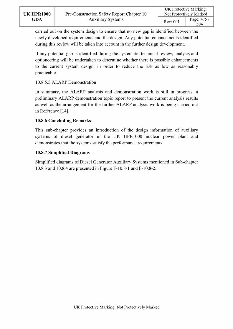
UK HPR1000
GDA
Pre-Construction Safety Report Chapter 10 Auxiliary Systems
UK Protective Marking: Not Protectively Marked
Rev: 001 Page: 475 /
504
UK Protective Marking: Not Protectively Marked
carried out on the system design to ensure that no new gap is identified between the newly developed requirements and the design. Any potential enhancements identified during this review will be taken into account in the further design development.
If any potential gap is identified during the systematic technical review, analysis and optioneering will be undertaken to determine whether there is possible enhancements to the current system design, in order to reduce the risk as low as reasonably practicable.
10.8.5.5 ALARP Demonstration
In summary, the ALARP analysis and demonstration work is still in progress, a preliminary ALARP demonstration topic report to present the current analysis results as well as the arrangement for the further ALARP analysis work is being carried out in Reference [14].
10.8.6 Concluding Remarks
This sub-chapter provides an introduction of the design information of auxiliary systems of diesel generator in the UK HPR1000 nuclear power plant and demonstrates that the systems satisfy the performance requirements.
10.8.7 Simplified Diagrams
Simplified diagrams of Diesel Generator Auxiliary Systems mentioned in Sub-chapter 10.8.3 and 10.8.4 are presented in Figure F-10.8-1 and F-10.8-2.
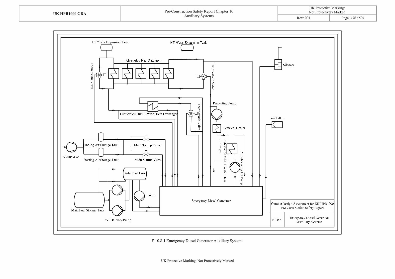
UK HPR1000 GDA Pre-Construction Safety Report Chapter 10
Auxiliary Systems
UK Protective Marking: Not Protectively Marked
Rev: 001 Page: 476 / 504
UK Protective Marking: Not Protectively Marked
F-10.8-1 Emergency Diesel Generator Auxiliary Systems
UK HPR1000 GDA Pre-Construction Safety Report Chapter 10
Auxiliary Systems
UK Protective Marking:
Not Protectively Marked
Rev: 001 Page: 477 / 504
UK Protective Marking: Not Protectively Marked
F-10.8-2SBO Diesel Generator Auxiliary
Systems Fuel Delivery Pump
Daily Fuel Tank
Pump
SBO Diesel GeneratorGeneric Design Assessment for UK HPR1000
Pre-Construction Safety Report
Starting Air Storage Tank
Starting Air Storage TankCompressor
Main Startup Valve and
Pneumatic Motor
Cooling Water Expansion Tank
Th
ermo
static Valv
e
Th
ermo
static Valv
e
Preheating Pump
Electrical Heater
Lu
bricatio
n O
il/HT
Water H
eat
Ex
chan
ger P
re-lub
ricating
Oil P
um
p
Lubrication Oil/LT Water Heat Exchanger
Th
ermo
static Valv
e
Air-cooled Heat Radiator
Air Filter
Silencer
Main Fuel Storage Tank
Compressor
Main Startup Valve and
Pneumatic Motor
F-10.8-2 SBO Diesel Generator Auxiliary Systems
UK HPR1000
GDA
Pre-Construction Safety Report Chapter 10 Auxiliary Systems
UK Protective Marking: Not Protectively Marked
Rev: 001 Page: 478 /
504
UK Protective Marking: Not Protectively Marked
10.9 Concluding Remarks
Chapter 10 provides an introduction on the design information of auxiliary systems in UK HPR1000 nuclear power plant including system design considerations, design bases, system description and operation, design substantiation, etc.
The consistency of the current design auxiliary systems design of UK HPR1000 against the codes and standards based on the UK context is currently being analysed. As the development of the principles may have an influence on the current design, a systematic review will be carried out after the preliminary work has been finished. If any gap is identified during the technical review, ALARP demonstration will be carried out to reduce the risk as low as reasonably practicable.
Based on the strategy of Mechanical Engineering safety case, various references have been prepared during the step 3, which provide support for the PCSR and form a robust safety case.
Concluding remarks of each sub-chapter are presented in sections 10.3.6, 10.4.11, 10.5.8, 10.6.20, 10.7.7, 10.8.6.
UK HPR1000
GDA
Pre-Construction Safety Report Chapter 10 Auxiliary Systems
UK Protective Marking: Not Protectively Marked
Rev: 001 Page: 479 /
504
UK Protective Marking: Not Protectively Marked
10.10 References
[1] CGN, UK HPR1000 Design Reference Report, NE15BW-X-GL-0000-000047, Revision E, 2019.
[2] CGN, General Safety Requirements, GHX00100017DOZJ03GN, Revision F, 2019.
[3] CGN, Methodology of Safety Categorisation and Classification, GHX00100062DOZJ03GN, Revision B, 2018.
[4] CGN, The General Requirements of Protection Design against Internal and External Hazards, GHX00100028DOZJ03GN, Revision D, 2018.
[5] CGN, Equipment Qualification Methodology, GHX80000003DOZJ03GN, Revision A, 2019.
[6] CGN, Material Selection Methodology, GHX00100006DPCH03GN, Revision C, 2019.
[7] CGN, HBSCs List, GHX00100005DIKX03GN, Revision B, 2019.
[8] CGN, HFE Guidelines for Local Area Design, GHX00100001DIGL03GN, Revision C, 2018.
[9] CGN, Local area HMIs and workspaces design HF review report, GHX00100012DIKX03GN, Revision B, 2019.
[10] CGN, Baseline Human Factors Assessment Report, GHX00100107DIKX03GN, Revision A, 2019.
[11] CGN, Design Assurance for the Mechanical Equipment Supplier, GHX81000001DNHX04GN, Revision A, 2019.
[12] CGN, General Principles for Application of Laws, Regulation, Codes and Standards, GHX00100018DOZJ03GN, Revision F, 2018.
[13] CGN, Suitability Analysis of Codes and Standards in Mechanical Engineering, GHX00800005DNHX02GN, Revision A, 2018.
[14] CGN, ALARP Demonstration for Auxiliary Systems, GHX00100053KPGB03GN, Revision D, 2019.
[15] CGN, Technical Specification for Nuclear Lifting and Handling Equipment, GHX45600011DPZS45GN, Revision B, 2019.
[16] CGN, DMR-Reactor Building Handling Equipment System Manual Chapter 2 Brief Introduction to the System, GHX17DMR002DPZS45GN, Revision A, 2018.
UK HPR1000
GDA
Pre-Construction Safety Report Chapter 10 Auxiliary Systems
UK Protective Marking: Not Protectively Marked
Rev: 001 Page: 480 /
504
UK Protective Marking: Not Protectively Marked
[17] CGN, DMR-Reactor Building Handling Equipment System Manual Chapter 3 System Functions and Design Bases, GHX17DMR003DPZS45GN, Revision B, 2019.
[18] CGN, DMR-Reactor Building Handling Equipment System Manual Chapter 4 System and Component Design, GHX17DMR004DPZS45GN, Revision A, 2018.
[19] CGN, Lifting Schedule of Reactor Pressure Vessel Head Assembly, GHX44100002DPFJ44DS, Revision C, 2019.
[20] CGN, Fault Condition Analysis of the Cranes during Lifting Operations, GHX45600010DPZS45GN, Revision B, 2019.
[21] CGN, DMR-Reactor Building Handling Equipment System Manual Chapter 6 System Operation and Maintenance, GHX17DMR006DPZS45GN, Revision B, 2019.
[22] CGN, DMK-Fuel Building Handling Equipment System Manual Chapter 2 Brief Introduction to the System, GHX17DMK002DPZS45GN, Revision A, 2018.
[23] CGN, DMK-Fuel Building Handling Equipment System Manual Chapter 3 System Functions and Design Bases, GHX17DMK003DPZS45GN, Revision A, 2018.
[24] CGN, DMK-Fuel Building Handling Equipment System Manual Chapter 4 System and Component Design, GHX17DMK004DPZS45GN, Revision A, 2018.
[25] CGN, DMK-Fuel Building Handling Equipment System Manual Chapter 6 System Operation and Maintenance, GHX17DMK006DPZS45GN, Revision B, 2019.
[26] CGN, RCV-Chemical and Volume Control System Design Manual Chapter 2 Brief Introduction to the System, GHX17RCV002DNHX45GN, Revision B, 2019.
[27] CGN, RCV-Chemical and Volume Control System Design Manual Chapter 4 System and Component Design, GHX17RCV004DNHX45GN, Revision C, 2019.
[28] CGN, RCV-Chemical and Volume Control System Design Manual Chapter 5 Layout Requirements and Environment Condition, GHX17RCV005DNHX45GN, Revision B, 2019.
[29] CGN, RCV-Chemical and Volume Control System Design Manual Chapter 6 System Operation and Maintenance, GHX17RCV006DNHX45GN, Revision
UK HPR1000
GDA
Pre-Construction Safety Report Chapter 10 Auxiliary Systems
UK Protective Marking: Not Protectively Marked
Rev: 001 Page: 481 /
504
UK Protective Marking: Not Protectively Marked
C, 2019.
[30] CGN, RCV-Chemical and Volume Control System Design Manual Chapter 3 System Functions and Design Bases, GHX17RCV003DNHX45GN, Revision C, 2019.
[31] CGN, Methodology of Design for System Commissioning Programme, GHX26SCPC00DOYX45GN, Revision B, 2019.
[32] CGN, Periodic Test Design Methodology, NE15BWXYX0000000021, Revision B, 2018.
[33] CGN, RCV-Chemical and Volume Control System Design Manual Chapter 9 Flow Diagrams, GHX17RCV009DNHX45GN, Revision C, 2019.
[34] CGN, REA-Reactor Boron and Water Makeup System Design Manual Chapter 2 Brief Introduction to the System, GHX17REA002DNHX45GN, Revision A, 2018.
[35] CGN, REA-Reactor Boron and Water Makeup System Design Manual Chapter 4 System and Component Design, GHX17REA004DNHX45GN, Revision B, 2019.
[36] CGN, REA-Reactor Boron and Water Makeup System Design Manual Chapter 5 Layout Requirements and Environment Condition, GHX17REA005DNHX45GN, Revision B, 2019.
[37] CGN, REA-Reactor Boron and Water Makeup System Design Manual Chapter 6 System Operation and Maintenance, GHX17REA006DNHX45GN, Revision B, 2018.
[38] CGN, REA-Reactor Boron and Water Makeup System Design Manual Chapter 3 System Functions and Design Bases, GHX17REA003DNHX45GN, Revision C, 2019.
[39] CGN, REA-Reactor Boron and Water Makeup System Design Manual Chapter 9 Flow Diagrams, GHX17REA009DNHX45GN, Revision B, 2018.
[40] CGN, TEP-Coolant Storage and Treatment System Design Manual Chapter 2 Brief Introduction to the System, GHX17TEP002DNFF45GN, Revision B, 2019.
[41] CGN, TEP-Coolant Storage and Treatment System Design Manual Chapter 4 System and Component Design, GHX17TEP004DNFF45GN, Revision D, 2019.
[42] CGN, TEP-Coolant Storage and Treatment System Design Manual Chapter 5 Layout Requirements and Environment Condition,
UK HPR1000
GDA
Pre-Construction Safety Report Chapter 10 Auxiliary Systems
UK Protective Marking: Not Protectively Marked
Rev: 001 Page: 482 /
504
UK Protective Marking: Not Protectively Marked
GHX17TEP005DNFF45GN, Revision B, 2019.
[43] CGN, TEP-Coolant Storage and Treatment System Design Manual Chapter 6 System Operation and Maintenance, GHX17TEP006DNFF45GN, Revision B, 2019.
[44] CGN, TEP-Coolant Storage and Treatment System Design Manual Chapter 3 System Functions and Design Bases, GHX17TEP003DNFF45GN, Revision C, 2019.
[45] CGN, TEP-Coolant Storage and Treatment System Design Manual Chapter 9 Flow Diagrams, GHX17TEP009DNFF45GN, Revision B, 2018.
[46] CGN, REN-Nuclear Sampling System Design Manual Chapter 2 Brief Introduction to the System, GHX17REN002DNHX45GN, Revision A, 2018.
[47] CGN, REN-Nuclear Sampling System Design Manual Chapter 4 System and Component Design, GHX17REN004DNHX45GN, Revision B, 2019.
[48] CGN, REN-Nuclear Sampling System Design Manual Chapter 5 Layout Requirements and Environment Condition, GHX17REN005DNHX45GN, Revision B, 2019.
[49] CGN, REN-Nuclear Sampling System Design Manual Chapter 6 System Operation and Maintenance, GHX17REN006DNHX45GN, Revision B, 2018.
[50] CGN, REN-Nuclear Sampling System Design Manual Chapter 3 System Functions and Design Bases, GHX17REN003DNHX45GN, Revision C, 2019.
[51] CGN, REN-Nuclear Sampling System Design Manual Chapter 9 Flow Diagrams, GHX17REN009DNHX45GN, Revision B, 2018.
[52] CGN, PTR-Fuel Pool Cooling and Treatment System Design Manual Chapter 2 Brief Introduction to the System, GHX17PTR002DNHX45GN, Revision A, 2018.
[53] CGN, PTR-Fuel Pool Cooling and Treatment System Design Manual Chapter 3 System Functions and Design Bases, GHX17PTR003DNHX45GN, Revision B, 2019.
[54] CGN, PTR-Fuel Pool Cooling and Treatment System Design Manual Chapter 4 System and Component Design, GHX17PTR004DNHX45GN, Revision B, 2019.
[55] CGN, PTR-Fuel Pool Cooling and Treatment System Design Manual Chapter 6 System Operation and Maintenance, GHX17PTR006DNHX45GN, Revision B, 2018.
[56] CGN, PTR-Fuel Pool Cooling and Treatment System Design Manual Chapter
UK HPR1000
GDA
Pre-Construction Safety Report Chapter 10 Auxiliary Systems
UK Protective Marking: Not Protectively Marked
Rev: 001 Page: 483 /
504
UK Protective Marking: Not Protectively Marked
5 Layout Requirements and Environment Condition, GHX17PTR005DNHX45GN, Revision B, 2019.
[57] CGN, PTR-Fuel Pool Cooling and Treatment System Design Manual Chapter 9 Flow Diagrams, GHX17PTR009DNHX45GN, Revision B, 2018.
[58] CGN, RRI-Component Cooling Water System Design Manual Chapter 2 Brief Introduction to the System, GHX17RRI002DNHX45GN, Revision B, 2019.
[59] CGN, RRI-Component Cooling Water System Design Manual Chapter 3 System Functions and Design Bases, GHX17RRI003DNHX45GN, Revision C, 2019.
[60] CGN, RRI-Component Cooling Water System Design Manual Chapter 4 System and Component Design, GHX17RRI004DNHX45GN, Revision C, 2019.
[61] CGN, RRI-Component Cooling Water System Design Manual Chapter 5 Layout Requirements and Environment Condition, GHX17RRI005DNHX45GN, Revision B, 2017.
[62] CGN, RRI-Component Cooling Water System Design Manual Chapter 6 System Operation and Maintenance, GHX17RRI006DNHX45GN, Revision D, 2019.
[63] CGN, RRI-Component Cooling Water System Design Manual Chapter 9 Flow Diagrams, GHX17RRI009DNHX45GN, Revision C, 2019.
[64] CGN, SEC-Essential Service Water System Manual Chapter 2 Brief Introduction to the System, GHX17SEC002DCSG45GN, Revision C, 2019.
[65] CGN, SEC-Essential Service Water System Manual Chapter 4 System and Component Design, GHX17SEC004DCSG45GN, Revision C, 2019.
[66] CGN, SEC/RRI System Analysis Report, GHX00800001DCSG02GN, Revision C, 2019.
[67] CGN, SEC-Essential Service Water System Manual Chapter 5 Layout Requirements and Environment Condition, GHX17SEC005DCSG45GN, Revision C, 2019.
[68] CGN, SEC-Essential Service Water System Manual Chapter 6 System Operation and Maintenance, GHX17SEC006DCSG45GN, Revision D, 2019.
[69] CGN, SEC-Essential Service Water System Manual Chapter 3 System Functions and Design Bases, GHX17SEC003DCSG45GN, Revision C, 2019.
[70] CGN, SEC-Essential Service Water System Manual Chapter 9 Flow Diagram , GHX17SEC009DCSG45GN, Revision D, 2019.
UK HPR1000
GDA
Pre-Construction Safety Report Chapter 10 Auxiliary Systems
UK Protective Marking: Not Protectively Marked
Rev: 001 Page: 484 /
504
UK Protective Marking: Not Protectively Marked
[71] CGN, DWN-Nuclear Auxiliary Building Ventilation System Manual Chapter 4 System and Component Design, GHX17DWN004DCNT45GN, Revision C, 2019.
[72] CGN, DWN-Nuclear Auxiliary Building Ventilation System Manual Chapter 2 Brief Introduction to the System, GHX17DWN002DCNT45GN, Revision B, 2018.
[73] CGN, DWN-Nuclear Auxiliary Building Ventilation System Manual Chapter 5 Layout Requirements and Environment Condition, GHX17DWN005DCNT45GN, Revision D, 2019.
[74] CGN, DWN-Nuclear Auxiliary Building Ventilation System Manual Chapter 6 System Operation and Maintenance, GHX17DWN006DCNT45GN, Revision D, 2019.
[75] CGN, DWN-Nuclear Auxiliary Building Ventilation System Manual Chapter 3 System Functions and Design Bases, GHX17DWN003DCNT45GN, Revision C, 2019.
[76] CGN, DWN-Nuclear Auxiliary Building Ventilation System Manual Chapter 9 Flow Diagrams, GHX17DWN009DCNT45GN, Revision E, 2019.
[77] CGN, DWK-Fuel Building Ventilation System Manual Chapter 4 System and Component Design, GHX17DWK004DCNT45GN, Revision C, 2019.
[78] CGN, DWK-Fuel Building Ventilation System Manual Chapter 2 Brief Introduction to the System, GHX17DWK002DCNT45GN, Revision B, 2018.
[79] CGN, DWK-Fuel Building Ventilation System Manual Chapter 5 Layout Requirements and Environment Condition, GHX17DWK005DCNT45GN, Revision D, 2019.
[80] CGN, DWK-Fuel Building Ventilation System Manual Chapter 3 System Functions and Design Bases, GHX17DWK003DCNT45GN, Revision C, 2019.
[81] CGN, DWK-Fuel Building Ventilation System Manual Chapter 6 System Operation and Maintenance, GHX17DWK006DCNT45GN, Revision B, 2018.
[82] CGN, DWK-Fuel Building Ventilation System Manual Chapter 9 Flow Diagrams, GHX17DWK009DCNT45GN, Revision C, 2019.
[83] CGN, EVR-Containment Cooling and Ventilation System Manual Chapter 4 System and Component Design, GHX17EVR004DCNT45GN, Revision B, 2019.
[84] CGN, EVR-Containment Cooling and Ventilation System Manual Chapter 2 Brief Introduction to the System, GHX17EVR002DCNT45GN, Revision B,
UK HPR1000
GDA
Pre-Construction Safety Report Chapter 10 Auxiliary Systems
UK Protective Marking: Not Protectively Marked
Rev: 001 Page: 485 /
504
UK Protective Marking: Not Protectively Marked
2018.
[85] CGN, EVR-Containment Cooling and Ventilation System Manual Chapter 5 Layout Requirements and Environment Condition, GHX17EVR005DCNT45GN, Revision C, 2019.
[86] CGN, EVR-Containment Cooling and Ventilation System Manual Chapter 6 System Operation and Maintenance, GHX17EVR006DCNT45GN, Revision C, 2019.
[87] CGN, EVR-Containment Cooling and Ventilation System Manual Chapter 3 System Functions and Design Bases, GHX17EVR003DCNT45GN, Revision C, 2019.
[88] CGN, EVR-Containment Cooling and Ventilation System Manual Chapter 9 Flow Diagrams, GHX17EVR009DCNT45GN, Revision C, 2019.
[89] CGN, EVF-Containment Internal Filtration System Manual Chapter 4 System and Component Design, GHX17EVF004DCNT45GN, Revision C, 2019.
[90] CGN, EVF-Containment Internal Filtration System Manual Chapter 2 Brief Introduction to the System, GHX17EVF002DCNT45GN, Revision D, 2019.
[91] CGN, EVF-Containment Internal Filtration System Manual Chapter 5 Layout Requirements and Environment Condition, GHX17EVF005DCNT45GN, Revision C, 2019.
[92] CGN, EVF-Containment Internal Filtration System Manual Chapter 6 System Operation and Maintenance, GHX17EVF006DCNT45GN, Revision D 2019.
[93] CGN, EVF-Containment Internal Filtration System Manual Chapter 3 System Functions and Design Bases, GHX17EVF003DCNT45GN, Revision D, 2019.
[94] CGN, EVF-Containment Internal Filtration System Manual Chapter 9 Flow Diagrams, GHX17EVF009DCNT45GN, Revision C, 2019.
[95] CGN, EBA-Containment Sweeping and Blowdown Ventilation System Manual Chapter 4 System and Component Design, GHX17EBA004DCNT45GN, Revision C, 2019.
[96] CGN, EBA-Containment Sweeping and Blowdown Ventilation System Manual Chapter 2 Brief Introduction to the System, GHX17EBA002DCNT45GN, Revision C, 2019.
[97] CGN, EBA-Containment Sweeping and Blowdown Ventilation System Manual Chapter 5 Layout Requirements and Environment Condition, GHX17EBA005DCNT45GN, Revision D, 2019.
[98] CGN, EBA-Containment Sweeping and Blowdown Ventilation System Manual
UK HPR1000
GDA
Pre-Construction Safety Report Chapter 10 Auxiliary Systems
UK Protective Marking: Not Protectively Marked
Rev: 001 Page: 486 /
504
UK Protective Marking: Not Protectively Marked
Chapter 6 System Operation and Maintenance, GHX17EBA006DCNT45GN, Revision D, 2019.
[99] CGN, EBA-Containment Sweeping and Blowdown Ventilation System Manual Chapter 3 System Functions and Design Bases, GHX17EBA003DCNT45GN, Revision D, 2019.
[100] CGN, EBA-Containment Sweeping and Blowdown Ventilation System Manual Chapter 9 Flow Diagrams, GHX17EBA009DCNT45GN, Revision E, 2019.
[101] CGN, EDE-Annulus Ventilation System Manual Chapter 4 System and Component Design, GHX17EDE004DCNT45GN, Revision B, 2019.
[102] CGN, EDE-Annulus Ventilation System Manual Chapter 2 Brief Introduction to the System, GHX17EDE002DCNT45GN, Revision B, 2018.
[103] CGN, EDE-Annulus Ventilation System Manual Chapter 5 Layout Requirements and Environment Condition, GHX17EDE005DCNT45GN, Revision B, 2018.
[104] CGN, EDE-Annulus Ventilation System Manual Chapter 6 System Operation and Maintenance, GHX17EDE006DCNT45GN, Revision B, 2018.
[105] CGN, EDE-Annulus Ventilation System Manual Chapter 3 System Functions and Design Bases, GHX17EDE003DCNT45GN, Revision B, 2019.
[106] CGN, EDE-Annulus Ventilation System Manual Chapter 9 Flow Diagrams, GHX17EDE009DCNT45GN, Revision C, 2019.
[107] CGN, DWL-Safeguard Building Controlled Area Ventilation System Manual Chapter 4 System and Component Design, GHX17DWL004DCNT45GN, Revision C, 2019.
[108] CGN, DWL-Safeguard Building Controlled Area Ventilation System Manual Chapter 2 Brief Introduction to the System, GHX17DWL002DCNT45GN, Revision B, 2018.
[109] CGN, DWL-Safeguard Building Controlled Area Ventilation System Manual Chapter 5 Layout Requirements and Environment Condition, GHX17DWL005DCNT45GN, Revision B, 2018.
[110] CGN, DWL-Safeguard Building Controlled Area Ventilation System Manual Chapter 6 System Operation and Maintenance, GHX17DWL006DCNT45GN, Revision B, 2018.
[111] CGN, DWL-Safeguard Building Controlled Area Ventilation System Manual Chapter 3 System Functions and Design Bases, GHX17DWL003DCNT45GN, Revision C, 2019.
UK HPR1000
GDA
Pre-Construction Safety Report Chapter 10 Auxiliary Systems
UK Protective Marking: Not Protectively Marked
Rev: 001 Page: 487 /
504
UK Protective Marking: Not Protectively Marked
[112] CGN, DWL-Safeguard Building Controlled Area Ventilation System Manual Chapter 9 Flow Diagrams, GHX17DWL009DCNT45GN, Revision C, 2019.
[113] CGN, DVL-Electrical Division of Safeguard Building Ventilation System Manual Chapter 4 System and Component Design, GHX17DVL004DCNT45GN, Revision C, 2019.
[114] CGN, DVL-Electrical Division of Safeguard Building Ventilation System Manual Chapter 2 Brief Introduction to the System, GHX17DVL002DCNT45GN, Revision B, 2018.
[115] CGN, DVL-Electrical Division of Safeguard Building Ventilation System Manual Chapter 5 Layout Requirements and Environment Condition, GHX17DVL005DCNT45GN, Revision B, 2018.
[116] CGN, DVL-Electrical Division of Safeguard Building Ventilation System Manual Chapter 6 System Operation and Maintenance, GHX17DVL006DCNT45GN, Revision D, 2019.
[117] CGN, DVL-Electrical Division of Safeguard Building Ventilation System Manual Chapter 3 System Functions and Design Bases, GHX17DVL003DCNT45GN, Revision C, 2019.
[118] CGN, DVL-Electrical Division of Safeguard Building Ventilation System Manual Chapter 9 Flow Diagrams, GHX17DVL009DCNT45GN, Revision E, 2019.
[119] CGN, DCL-Main Control Room Air Conditioning System Manual Chapter 4 System and Component Design, GHX17DCL004DCNT45GN, Revision D, 2019.
[120] CGN, DCL-Main Control Room Air Conditioning System Manual Chapter 2 Brief Introduction to the System, GHX17DCL002DCNT45GN, Revision B, 2019.
[121] CGN, DCL-Main Control Room Air Conditioning System Manual Chapter 5 Layout Requirements and Environment Condition, GHX17DCL005DCNT45GN, Revision C, 2019.
[122] CGN, DCL-Main Control Room Air Conditioning System Manual Chapter 6 System Operation and Maintenance, GHX17DCL006DCNT45GN, Revision C, 2019.
[123] CGN, DCL-Main Control Room Air Conditioning System Manual Chapter 3 System Functions and Design Bases, GHX17DCL003DCNT45GN, Revision B, 2019.
[124] CGN, DCL-Main Control Room Air Conditioning System Manual Chapter 9
UK HPR1000
GDA
Pre-Construction Safety Report Chapter 10 Auxiliary Systems
UK Protective Marking: Not Protectively Marked
Rev: 001 Page: 488 /
504
UK Protective Marking: Not Protectively Marked
Flow Diagrams, GHX17DCL009DCNT45GN, Revision C, 2019.
[125] CGN, DWW-Access Building Controlled Area Ventilation System Manual Chapter 4 System and Component Design, GHX17DWW004DCNT45GN, Revision C, 2019.
[126] CGN, DWW-Access Building Controlled Area Ventilation System Manual Chapter 2 Brief Introduction to the System, GHX17DWW002DCNT45GN, Revision B, 2018.
[127] CGN, DWW-Access Building Controlled Area Ventilation System Manual Chapter 5 Layout Requirements and Environment Condition, GHX17DWW005DCNT45GN, Revision B, 2018.
[128] CGN, DWW-Access Building Controlled Area Ventilation System Manual Chapter 6 System Operation and Maintenance, GHX17DWW006DCNT45GN, Revision B, 2018.
[129] CGN, DWW-Access Building Controlled Area Ventilation System Manual Chapter 3 System Functions and Design Bases, GHX17DWW003DCNT45GN, Revision C, 2019.
[130] CGN, DWW-Access Building Controlled Area Ventilation System Manual Chapter 9 Flow Diagrams, GHX17DWW009DCNT45GN, Revision D, 2019.
[131] CGN, DVD-Diesel Building Ventilation System Manual Chapter 4 System and Component Design, GHX17DVD004DCNT45GN, Revision C, 2019.
[132] CGN, DVD-Diesel Building Ventilation System Manual Chapter 2 Brief Introduction to the System, GHX17DVD002DCNT45GN, Revision A, 2018.
[133] CGN, DVD-Diesel Building Ventilation System Manual Chapter 5 Layout Requirements and Environment Condition, GHX17DVD005DCNT45GN, Revision A, 2018.
[134] CGN, DVD-Diesel Building Ventilation System Manual Chapter 6 System Operation and Maintenance, GHX17DVD006DCNT45GN, Revision C, 2019.
[135] CGN, DVD-Diesel Building Ventilation System Manual Chapter 3 System Functions and Design Bases, GHX17DVD003DCNT45GN, Revision C, 2019.
[136] CGN, DVD-Diesel Building Ventilation System Manual Chapter 9 Flow Diagrams, GHX17DVD009DCNT45GN, Revision C, 2019.
[137] CGN, DXE-Extra Cooling Water and NI Firefighting Building Ventilation System Manual Chapter 4 System and Component Design, GHX17DXE004DCNT45GN, Revision A, 2019.
[138] CGN, DXE-Extra Cooling Water and NI Firefighting Building Ventilation
UK HPR1000
GDA
Pre-Construction Safety Report Chapter 10 Auxiliary Systems
UK Protective Marking: Not Protectively Marked
Rev: 001 Page: 489 /
504
UK Protective Marking: Not Protectively Marked
System Manual Chapter 2 Brief Introduction to the System, GHX17DXE002DCNT45GN, Revision A, 2019.
[139] CGN, DXE-Extra Cooling Water and NI Firefighting Building Ventilation System Manual Chapter 5 Layout Requirements and Environment Condition, GHX17DXE005DCNT45GN, Revision A, 2019.
[140] CGN, DXE-Extra Cooling Water and NI Firefighting Building Ventilation System Manual Chapter 6 System Operation and Maintenance, GHX17DXE006DCNT45GN, Revision A, 2019.
[141] CGN, DXE-Extra Cooling Water and NI Firefighting Building Ventilation System Manual Chapter 3 System Functions and Design Bases, GHX17DXE003DCNT45GN, Revision A, 2019.
[142] CGN, DXE-Extra Cooling Water and NI Firefighting Building Ventilation System Manual Chapter 9 Flow Diagrams, GHX17DXE009DCNT45GN, Revision A, 2019.
[143] CGN, DWQ-Waste Treatment Building Ventilation System Manual Chapter 4 System and Component Design, GHX17DWQ004DCNT45GN, Revision B, 2019.
[144] CGN, DWQ-Waste Treatment Building Ventilation System Manual Chapter 2 Brief Introduction to the System, GHX17DWQ002DCNT45GN, Revision B, 2018.
[145] CGN, DWQ-Waste Treatment Building Ventilation System Manual Chapter 5 Layout Requirements and Environment Condition, GHX17DWQ005DCNT45GN, Revision B, 2018.
[146] CGN, DWQ-Waste Treatment Building Ventilation System Manual Chapter 6 System Operation and Maintenance, GHX17DWQ006DCNT45GN, Revision A, 2018.
[147] CGN, DWQ-Waste Treatment Building Ventilation System Manual Chapter 3 System Functions and Design Bases, GHX17DWQ003DCNT45GN, Revision B, 2019.
[148] CGN, DWQ-Waste Treatment Building Ventilation System Manual Chapter 9 Flow Diagrams, GHX17DWQ009DCNT45GN, Revision E, 2019.
[149] CGN, DEL-Safety Chilled Water System Manual Chapter 4 System and Component Design, GHX17DEL004DCNT45GN, Revision C, 2019.
[150] CGN, DEL-Safety Chilled Water System Manual Chapter 2 Brief Introduction to the System, GHX17DEL002DCNT45GN, Revision B, 2018.
UK HPR1000
GDA
Pre-Construction Safety Report Chapter 10 Auxiliary Systems
UK Protective Marking: Not Protectively Marked
Rev: 001 Page: 490 /
504
UK Protective Marking: Not Protectively Marked
[151] CGN, DEL-Safety Chilled Water System Manual Chapter 5 Layout Requirements and Environment Condition, GHX17DEL005DCNT45GN, Revision B, 2018.
[152] CGN, DEL-Safety Chilled Water System Manual Chapter 6 System Operation and Maintenance, GHX17DEL006DCNT45GN, Revision B, 2018.
[153] CGN, DEL-Safety Chilled Water System Manual Chapter 3 System Functions and Design Bases, GHX17DEL003DCNT45GN, Revision B, 2019.
[154] CGN, DEL-Safety Chilled Water System Manual Chapter 9 Flow Diagrams, GHX17DEL009DCNT45GN, Revision C, 2019.
[155] CGN, HVAC Systems Analysis Report—Site Adaptability Modification in UK HPR1000, GHX08000001DCNT03TR, Revision B, 2019.
[156] CGN, Optioneering Report of the HEPA Filters Types, GHX08000003DCNT03TR, Revision A, 2019.
[157] CGN, JDT-NI Fire Alarm System Design Manual Chapter 3 System Functions and Design Bases, GHX17JDT003DETX45GN, Revision A, 2019.
[158] CGN, JDT-NI Fire Alarm System Design Manual Chapter 6 System Operation and Maintenance, GHX17JDT006DETX45GN, Revision A, 2019.
[159] CGN, JDT-NI Fire Alarm System Design Manual Chapter 9 Flow Diagrams, GHX17JDT009DETX45GN, Revision A, 2019.
[160] CGN, JAC-Fire-fighting Water Production System Design Manual Chapter 2 Brief Introduction to the System, GHX17JAC002DCSG45GN, Revision B, 2019.
[161] CGN, JPI-Fire-fighting Water System for Nuclear Island System Design Manual Chapter 2 Brief Introduction to the System, GHX17JPI002DCSG45GN, Revision C, 2019.
[162] CGN, JPV-Fire Extinguishing System for Nuclear Island Diesel Generator Building Chapter 2 Brief Introduction to the System, GHX17JPV002DCSG45GN, Revision A, 2019.
[163] CGN, JAC-Fire-fighting Water Production System Design Manual Chapter 4 System and Component Design, GHX17JAC004DCSG45GN, Revision B, 2019.
[164] CGN, JPI-Fire-fighting Water System for Nuclear Island System Design Manual Chapter 4 System and Component Design, GHX17JPI004DCSG45GN, Revision D, 2019
[165] CGN, JPV-Fire Extinguishing System for Nuclear Island Diesel Generator
UK HPR1000
GDA
Pre-Construction Safety Report Chapter 10 Auxiliary Systems
UK Protective Marking: Not Protectively Marked
Rev: 001 Page: 491 /
504
UK Protective Marking: Not Protectively Marked
Building Chapter 4 System and Component Design, GHX17JPV004DCSG45GN, Revision A, 2019.
[166] CGN, JAC-Fire-fighting Water Production System Design Manual Chapter 5 Layout Requirements and Environment Condition, GHX17JAC005DCSG45GN, Revision B, 2019.
[167] CGN, JPI-Fire-fighting Water System for Nuclear Island System Design Manual Chapter 5 Layout Requirements and Environment Condition, GHX17JPI005DCSG45GN, Revision D, 2019.
[168] CGN, JPV-Fire Extinguishing System for Nuclear Island Diesel Generator Building Chapter 5 Layout Requirements and Environment Condition, GHX17JPV005DCSG45GN, Revision A, 2019.
[169] CGN, JAC-Fire-fighting Water Production System Design Manual Chapter 6 System Operation and Maintenance, GHX17JAC006DCSG45GN, Revision C, 2019.
[170] CGN, JPI-Fire-fighting Water System for Nuclear Island System Design Manual Chapter 6 System Operation and Maintenance, GHX17JPI006DCSG45GN, Revision C, 2019.
[171] CGN, JPV-Fire Extinguishing System for Nuclear Island Diesel Generator Building Chapter 6 System Operation and Maintenance, GHX17JPV006DCSG45GN, Revision A, 2019.
[172] CGN, JAC-Fire-fighting Water Production System Design Manual Chapter 3 System Functions and Design Bases, GHX17JAC003DCSG45GN, Revision C, 2019
[173] CGN, JPI-Fire-fighting Water System for Nuclear Island System Design Manual Chapter 3 System Functions and Design Bases, GHX17JPI003DCSG45GN, Revision C, 2019.
[174] CGN, JPV-Fire Extinguishing System for Nuclear Island Diesel Generator Building Chapter 3 System Functions and Design Bases, GHX17JPV003DCSG45GN, Revision A, 2019.
[175] CGN, JAC-Fire-fighting Water Production System Design Manual Chapter 9 System Operation and Maintenance, GHX17JAC009DCSG45GN, Revision C, 2019.
[176] CGN, JPI-Fire-fighting Water System for Nuclear Island System Design Manual Chapter 9 System Operation and Maintenance, GHX17JPI009DCSG45GN, Revision F, 2019.
[177] CGN, JPV-Fire Extinguishing System for Nuclear Island Diesel Generator
UK HPR1000
GDA
Pre-Construction Safety Report Chapter 10 Auxiliary Systems
UK Protective Marking: Not Protectively Marked
Rev: 001 Page: 492 /
504
UK Protective Marking: Not Protectively Marked
Building Chapter 9 System Operation and Maintenance, GHX17JPV009DCSG45GN, Revision A, 2019.
[178] CGN, DFL-Smoke Control System Manual Chapter 4 System and Component Design, GHX17DFL004DCNT45GN, Revision B, 2019.
[179] CGN, DFL-Smoke Control System Manual Chapter 2 Brief Introduction to the System, GHX17DFL002DCNT45GN, Revision C, 2019.
[180] CGN, DFL-Smoke Control System Manual Chapter 6 System Operation and Maintenance, GHX17DFL006DCNT45GN, Revision C, 2019.
[181] CGN, DFL-Smoke Control System Manual Chapter 3 System Functions and Design Bases, GHX17DFL003DCNT45GN, Revision C, 2019.
[182] CGN, DFL-Smoke Control System Manual Chapter 5 Layout Requirements and Environment Condition, GHX17DFL005DCNT45GN, Revision C, 2019.
[183] CGN, DFL-Smoke Control System Manual Chapter 9 Flow Diagrams, GHX17DFL009DCNT45GN, Revision D, 2019.
[184] CGN, LHP/LHQ/LHR Emergency Power Supply (EDG) System Design Manual Chapter 4 System and Component Design, GHX17LHP004DCCJ45GN, Revision B, 2019.
[185] CGN, LHP/LHQ/LHR Emergency Power Supply (EDG) System Design Manual Chapter 9 Flow Diagrams, GHX17LHP009DCCJ45GN, Revision A, 2019.
[186] CGN, LHP/LHQ/LHR Emergency Power Supply (EDG) System Design Manual Chapter 5 Layout Requirements and Environment Condition, GHX17LHP005DCCJ45GN, Revision A, 2019.
[187] CGN, LHP/LHQ/LHR Emergency Power Supply (EDG) System Design Manual Chapter 6 System Operation and Maintenance, GHX17LHP006DEDQ45GN, Revision C, 2019.
[188] CGN, JDT-NI Fire Alarm System Design Manual Chapter 4 System and Component Design, GHX17JDT004DETX45GN, Revision A, 2019.
[189] CGN, JDT-NI Fire Alarm System Design Manual Chapter 5 Layout Requirements and Environment Condition, GHX17JDT005DETX45GN, Revision A, 2019.
[190] CGN, LHU/LHV SBO Power Supply (SBO DG) System Design Manual Chapter 4 System and Component Design, GHX17LHU004DCCJ45GN, Revision B, 2019.
[191] CGN, LHU/LHV SBO Power Supply (SBO DG) System Design Manual
UK HPR1000
GDA
Pre-Construction Safety Report Chapter 10 Auxiliary Systems
UK Protective Marking: Not Protectively Marked
Rev: 001 Page: 493 /
504
UK Protective Marking: Not Protectively Marked
Chapter 9 Flow Diagrams, GHX17LHU009DCCJ45GN, Revision A, 2019.
[192] CGN, LHU/LHV SBO Power Supply (SBO DG) System Design Manual Chapter 5 Layout Requirements and Environment Condition, GHX17LHU005DCCJ45GN, Revision A, 2019
[193] CGN, LHU/LHV SBO Power Supply (SBO DG) System Design Manual Chapter 6 System Operation and Maintenance, GHX17LHU006DEDQ45GN, Revision C, 2019.
[194] General Nuclear System Limited, Pre-Construction Environmental Report Chapter 8 Conventional Impact Assessment, HPR/GDA/PCER/0008, Revision 001, 2020.
[195] General Nuclear System Limited, Pre-Construction Environmental Report Chapter 3 Demonstration of BAT, HPR/GDA/PCER/0003, Revision 001, 2020.
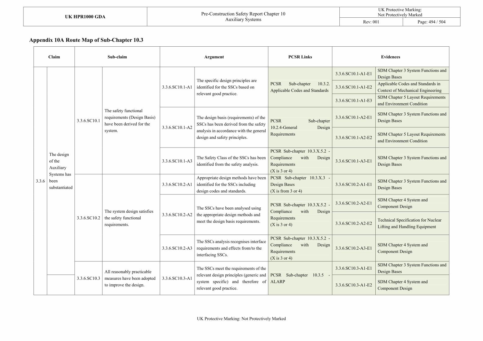
UK HPR1000 GDA Pre-Construction Safety Report Chapter 10
Auxiliary Systems
UK Protective Marking: Not Protectively Marked
Rev: 001 Page: 494 / 504
UK Protective Marking: Not Protectively Marked
Appendix 10A Route Map of Sub-Chapter 10.3
Claim Sub-claim Argument PCSR Links Evidences
3.3.6
The design
of the
Auxiliary
Systems has
been
substantiated
3.3.6.SC10.1
The safety functional
requirements (Design Basis)
have been derived for the
system.
3.3.6.SC10.1-A1
The specific design principles are
identified for the SSCs based on
relevant good practice.
PCSR Sub-chapter 10.3.2.
Applicable Codes and Standards
3.3.6.SC10.1-A1-E1 SDM Chapter 3 System Functions and
Design Bases
3.3.6.SC10.1-A1-E2 Applicable Codes and Standards in
Context of Mechanical Engineering
3.3.6.SC10.1-A1-E3 SDM Chapter 5 Layout Requirements
and Environment Condition
3.3.6.SC10.1-A2
The design basis (requirements) of the
SSCs has been derived from the safety
analysis in accordance with the general
design and safety principles.
PCSR Sub-chapter
10.2.4-General Design
Requirements
3.3.6.SC10.1-A2-E1 SDM Chapter 3 System Functions and
Design Bases
3.3.6.SC10.1-A2-E2 SDM Chapter 5 Layout Requirements
and Environment Condition
3.3.6.SC10.1-A3 The Safety Class of the SSCs has been
identified from the safety analysis.
PCSR Sub-chapter 10.3.X.5.2 -
Compliance with Design
Requirements
(X is 3 or 4)
3.3.6.SC10.1-A3-E1 SDM Chapter 3 System Functions and
Design Bases
3.3.6.SC10.2
The system design satisfies
the safety functional
requirements.
3.3.6.SC10.2-A1
Appropriate design methods have been
identified for the SSCs including
design codes and standards.
PCSR Sub-chapter 10.3.X.3 -
Design Bases
(X is from 3 or 4)
3.3.6.SC10.2-A1-E1 SDM Chapter 3 System Functions and
Design Bases
3.3.6.SC10.2-A2
The SSCs have been analysed using
the appropriate design methods and
meet the design basis requirements.
PCSR Sub-chapter 10.3.X.5.2 -
Compliance with Design
Requirements
(X is 3 or 4)
3.3.6.SC10.2-A2-E1 SDM Chapter 4 System and
Component Design
3.3.6.SC10.2-A2-E2 Technical Specification for Nuclear
Lifting and Handling Equipment
3.3.6.SC10.2-A3
The SSCs analysis recognises interface
requirements and effects from/to the
interfacing SSCs.
PCSR Sub-chapter 10.3.X.5.2 -
Compliance with Design
Requirements
(X is 3 or 4)
3.3.6.SC10.2-A3-E1 SDM Chapter 4 System and
Component Design
3.3.6.SC10.3
All reasonably practicable
measures have been adopted
to improve the design.
3.3.6.SC10.3-A1
The SSCs meet the requirements of the
relevant design principles (generic and
system specific) and therefore of
relevant good practice.
PCSR Sub-chapter 10.3.5 -
ALARP
3.3.6.SC10.3-A1-E1 SDM Chapter 3 System Functions and
Design Bases
3.3.6.SC10.3-A1-E2
SDM Chapter 4 System and
Component Design
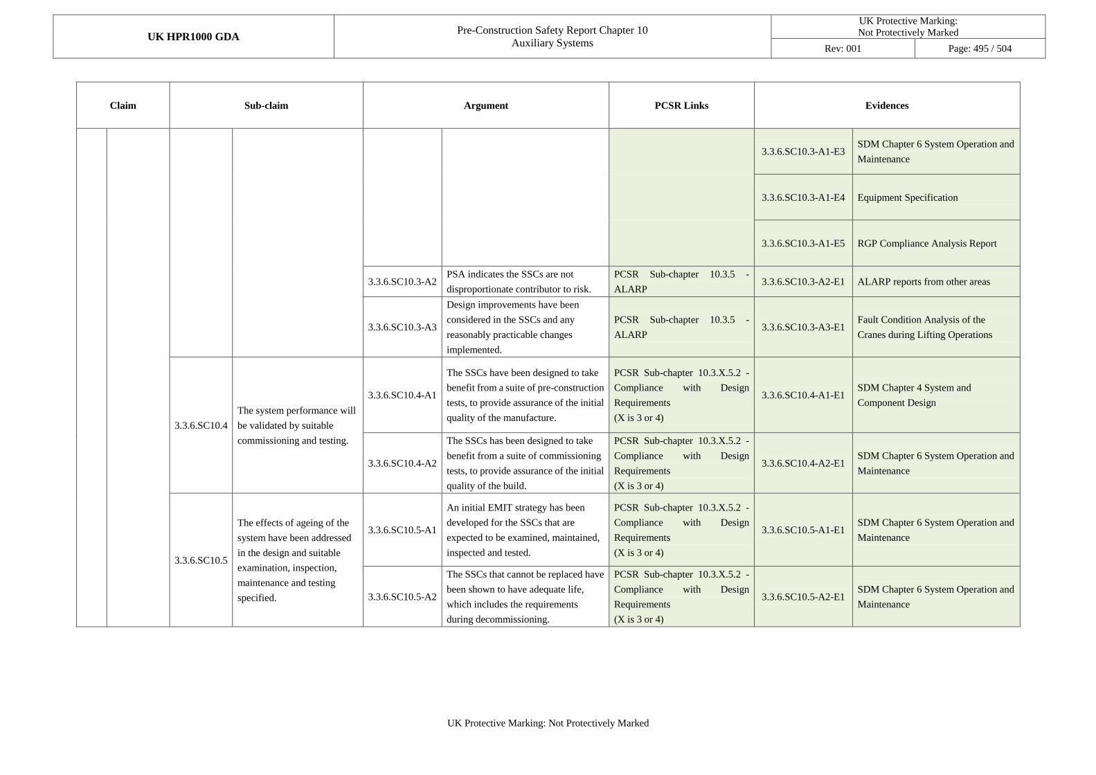
UK HPR1000 GDA Pre-Construction Safety Report Chapter 10
Auxiliary Systems
UK Protective Marking:
Not Protectively Marked
Rev: 001 Page: 495 / 504
UK Protective Marking: Not Protectively Marked
Claim Sub-claim Argument PCSR Links Evidences
3.3.6.SC10.3-A1-E3 SDM Chapter 6 System Operation and
Maintenance
3.3.6.SC10.3-A1-E4 Equipment Specification
3.3.6.SC10.3-A1-E5 RGP Compliance Analysis Report
3.3.6.SC10.3-A2 PSA indicates the SSCs are not
disproportionate contributor to risk.
PCSR Sub-chapter 10.3.5 -
ALARP 3.3.6.SC10.3-A2-E1 ALARP reports from other areas
3.3.6.SC10.3-A3
Design improvements have been
considered in the SSCs and any
reasonably practicable changes
implemented.
PCSR Sub-chapter 10.3.5 -
ALARP 3.3.6.SC10.3-A3-E1
Fault Condition Analysis of the
Cranes during Lifting Operations
3.3.6.SC10.4
The system performance will
be validated by suitable
commissioning and testing.
3.3.6.SC10.4-A1
The SSCs have been designed to take
benefit from a suite of pre-construction
tests, to provide assurance of the initial
quality of the manufacture.
PCSR Sub-chapter 10.3.X.5.2 -
Compliance with Design
Requirements
(X is 3 or 4)
3.3.6.SC10.4-A1-E1 SDM Chapter 4 System and
Component Design
3.3.6.SC10.4-A2
The SSCs has been designed to take
benefit from a suite of commissioning
tests, to provide assurance of the initial
quality of the build.
PCSR Sub-chapter 10.3.X.5.2 -
Compliance with Design
Requirements
(X is 3 or 4)
3.3.6.SC10.4-A2-E1 SDM Chapter 6 System Operation and
Maintenance
3.3.6.SC10.5
The effects of ageing of the
system have been addressed
in the design and suitable
examination, inspection,
maintenance and testing
specified.
3.3.6.SC10.5-A1
An initial EMIT strategy has been
developed for the SSCs that are
expected to be examined, maintained,
inspected and tested.
PCSR Sub-chapter 10.3.X.5.2 -
Compliance with Design
Requirements
(X is 3 or 4)
3.3.6.SC10.5-A1-E1 SDM Chapter 6 System Operation and
Maintenance
3.3.6.SC10.5-A2
The SSCs that cannot be replaced have
been shown to have adequate life,
which includes the requirements
during decommissioning.
PCSR Sub-chapter 10.3.X.5.2 -
Compliance with Design
Requirements
(X is 3 or 4)
3.3.6.SC10.5-A2-E1 SDM Chapter 6 System Operation and
Maintenance
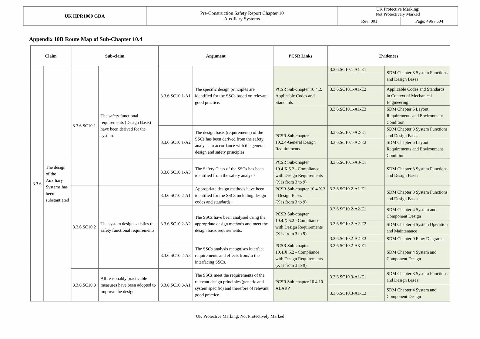
UK HPR1000 GDA Pre-Construction Safety Report Chapter 10
Auxiliary Systems
UK Protective Marking:
Not Protectively Marked
Rev: 001 Page: 496 / 504
UK Protective Marking: Not Protectively Marked
Appendix 10B Route Map of Sub-Chapter 10.4
Claim Sub-claim Argument PCSR Links Evidences
3.3.6
The design
of the
Auxiliary
Systems has
been
substantiated
3.3.6.SC10.1
The safety functional
requirements (Design Basis)
have been derived for the
system.
3.3.6.SC10.1-A1
The specific design principles are
identified for the SSCs based on relevant
good practice.
PCSR Sub-chapter 10.4.2.
Applicable Codes and
Standards
3.3.6.SC10.1-A1-E1 SDM Chapter 3 System Functions
and Design Bases
3.3.6.SC10.1-A1-E2 Applicable Codes and Standards
in Context of Mechanical
Engineering
3.3.6.SC10.1-A1-E3 SDM Chapter 5 Layout
Requirements and Environment
Condition
3.3.6.SC10.1-A2
The design basis (requirements) of the
SSCs has been derived from the safety
analysis in accordance with the general
design and safety principles.
PCSR Sub-chapter
10.2.4-General Design
Requirements
3.3.6.SC10.1-A2-E1 SDM Chapter 3 System Functions
and Design Bases
3.3.6.SC10.1-A2-E2 SDM Chapter 5 Layout
Requirements and Environment
Condition
3.3.6.SC10.1-A3 The Safety Class of the SSCs has been
identified from the safety analysis.
PCSR Sub-chapter
10.4.X.5.2 - Compliance
with Design Requirements
(X is from 3 to 9)
3.3.6.SC10.1-A3-E1
SDM Chapter 3 System Functions
and Design Bases
3.3.6.SC10.2 The system design satisfies the
safety functional requirements.
3.3.6.SC10.2-A1
Appropriate design methods have been
identified for the SSCs including design
codes and standards.
PCSR Sub-chapter 10.4.X.3
- Design Bases
(X is from 3 to 9)
3.3.6.SC10.2-A1-E1 SDM Chapter 3 System Functions
and Design Bases
3.3.6.SC10.2-A2
The SSCs have been analysed using the
appropriate design methods and meet the
design basis requirements.
PCSR Sub-chapter
10.4.X.5.2 - Compliance
with Design Requirements
(X is from 3 to 9)
3.3.6.SC10.2-A2-E1 SDM Chapter 4 System and
Component Design
3.3.6.SC10.2-A2-E2 SDM Chapter 6 System Operation
and Maintenance
3.3.6.SC10.2-A2-E3 SDM Chapter 9 Flow Diagrams
3.3.6.SC10.2-A3
The SSCs analysis recognises interface
requirements and effects from/to the
interfacing SSCs.
PCSR Sub-chapter
10.4.X.5.2 - Compliance
with Design Requirements
(X is from 3 to 9)
3.3.6.SC10.2-A3-E1
SDM Chapter 4 System and
Component Design
3.3.6.SC10.3
All reasonably practicable
measures have been adopted to
improve the design.
3.3.6.SC10.3-A1
The SSCs meet the requirements of the
relevant design principles (generic and
system specific) and therefore of relevant
good practice.
PCSR Sub-chapter 10.4.10 -
ALARP
3.3.6.SC10.3-A1-E1 SDM Chapter 3 System Functions
and Design Bases
3.3.6.SC10.3-A1-E2 SDM Chapter 4 System and
Component Design
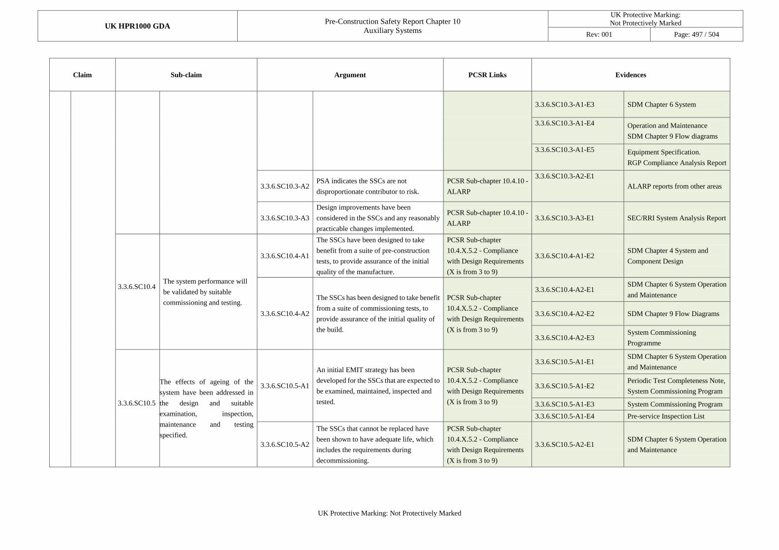
UK HPR1000 GDA Pre-Construction Safety Report Chapter 10
Auxiliary Systems
UK Protective Marking:
Not Protectively Marked
Rev: 001 Page: 497 / 504
UK Protective Marking: Not Protectively Marked
Claim Sub-claim Argument PCSR Links Evidences
3.3.6.SC10.3-A1-E3 SDM Chapter 6 System
3.3.6.SC10.3-A1-E4 Operation and Maintenance
SDM Chapter 9 Flow diagrams
3.3.6.SC10.3-A1-E5 Equipment Specification.
RGP Compliance Analysis Report
3.3.6.SC10.3-A2 PSA indicates the SSCs are not
disproportionate contributor to risk.
PCSR Sub-chapter 10.4.10 -
ALARP
3.3.6.SC10.3-A2-E1
ALARP reports from other areas
3.3.6.SC10.3-A3
Design improvements have been
considered in the SSCs and any reasonably
practicable changes implemented.
PCSR Sub-chapter 10.4.10 -
ALARP 3.3.6.SC10.3-A3-E1 SEC/RRI System Analysis Report
3.3.6.SC10.4
The system performance will
be validated by suitable
commissioning and testing.
3.3.6.SC10.4-A1
The SSCs have been designed to take
benefit from a suite of pre-construction
tests, to provide assurance of the initial
quality of the manufacture.
PCSR Sub-chapter
10.4.X.5.2 - Compliance
with Design Requirements
(X is from 3 to 9)
3.3.6.SC10.4-A1-E2 SDM Chapter 4 System and
Component Design
3.3.6.SC10.4-A2
The SSCs has been designed to take benefit
from a suite of commissioning tests, to
provide assurance of the initial quality of
the build.
PCSR Sub-chapter
10.4.X.5.2 - Compliance
with Design Requirements
(X is from 3 to 9)
3.3.6.SC10.4-A2-E1 SDM Chapter 6 System Operation
and Maintenance
3.3.6.SC10.4-A2-E2 SDM Chapter 9 Flow Diagrams
3.3.6.SC10.4-A2-E3 System Commissioning
Programme
3.3.6.SC10.5
The effects of ageing of the
system have been addressed in
the design and suitable
examination, inspection,
maintenance and testing
specified.
3.3.6.SC10.5-A1
An initial EMIT strategy has been
developed for the SSCs that are expected to
be examined, maintained, inspected and
tested.
PCSR Sub-chapter
10.4.X.5.2 - Compliance
with Design Requirements
(X is from 3 to 9)
3.3.6.SC10.5-A1-E1 SDM Chapter 6 System Operation
and Maintenance
3.3.6.SC10.5-A1-E2 Periodic Test Completeness Note,
System Commissioning Program
3.3.6.SC10.5-A1-E3 System Commissioning Program
3.3.6.SC10.5-A1-E4 Pre-service Inspection List
3.3.6.SC10.5-A2
The SSCs that cannot be replaced have
been shown to have adequate life, which
includes the requirements during
decommissioning.
PCSR Sub-chapter
10.4.X.5.2 - Compliance
with Design Requirements
(X is from 3 to 9)
3.3.6.SC10.5-A2-E1 SDM Chapter 6 System Operation
and Maintenance
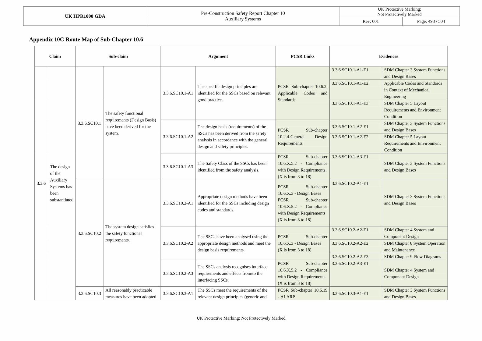
UK HPR1000 GDA Pre-Construction Safety Report Chapter 10
Auxiliary Systems
UK Protective Marking:
Not Protectively Marked
Rev: 001 Page: 498 / 504
UK Protective Marking: Not Protectively Marked
Appendix 10C Route Map of Sub-Chapter 10.6
Claim Sub-claim Argument PCSR Links Evidences
3.3.6
The design
of the
Auxiliary
Systems has
been
substantiated
3.3.6.SC10.1
The safety functional
requirements (Design Basis)
have been derived for the
system.
3.3.6.SC10.1-A1
The specific design principles are
identified for the SSCs based on relevant
good practice.
PCSR Sub-chapter 10.6.2.
Applicable Codes and
Standards
3.3.6.SC10.1-A1-E1 SDM Chapter 3 System Functions
and Design Bases
3.3.6.SC10.1-A1-E2 Applicable Codes and Standards
in Context of Mechanical
Engineering
3.3.6.SC10.1-A1-E3 SDM Chapter 5 Layout
Requirements and Environment
Condition
3.3.6.SC10.1-A2
The design basis (requirements) of the
SSCs has been derived from the safety
analysis in accordance with the general
design and safety principles.
PCSR Sub-chapter
10.2.4-General Design
Requirements
3.3.6.SC10.1-A2-E1 SDM Chapter 3 System Functions
and Design Bases
3.3.6.SC10.1-A2-E2 SDM Chapter 5 Layout
Requirements and Environment
Condition
3.3.6.SC10.1-A3 The Safety Class of the SSCs has been
identified from the safety analysis.
PCSR Sub-chapter
10.6.X.5.2 - Compliance
with Design Requirements,
(X is from 3 to 18)
3.3.6.SC10.1-A3-E1
SDM Chapter 3 System Functions
and Design Bases
3.3.6.SC10.2
The system design satisfies
the safety functional
requirements.
3.3.6.SC10.2-A1
Appropriate design methods have been
identified for the SSCs including design
codes and standards.
PCSR Sub-chapter
10.6.X.3 - Design Bases
PCSR Sub-chapter
10.6.X.5.2 - Compliance
with Design Requirements
(X is from 3 to 18)
3.3.6.SC10.2-A1-E1
SDM Chapter 3 System Functions
and Design Bases
3.3.6.SC10.2-A2
The SSCs have been analysed using the
appropriate design methods and meet the
design basis requirements.
PCSR Sub-chapter
10.6.X.3 - Design Bases
(X is from 3 to 18)
3.3.6.SC10.2-A2-E1 SDM Chapter 4 System and
Component Design
3.3.6.SC10.2-A2-E2 SDM Chapter 6 System Operation
and Maintenance
3.3.6.SC10.2-A2-E3 SDM Chapter 9 Flow Diagrams
3.3.6.SC10.2-A3
The SSCs analysis recognises interface
requirements and effects from/to the
interfacing SSCs.
PCSR Sub-chapter
10.6.X.5.2 - Compliance
with Design Requirements
(X is from 3 to 18)
3.3.6.SC10.2-A3-E1
SDM Chapter 4 System and
Component Design
3.3.6.SC10.3 All reasonably practicable
measures have been adopted 3.3.6.SC10.3-A1
The SSCs meet the requirements of the
relevant design principles (generic and
PCSR Sub-chapter 10.6.19
- ALARP 3.3.6.SC10.3-A1-E1
SDM Chapter 3 System Functions
and Design Bases
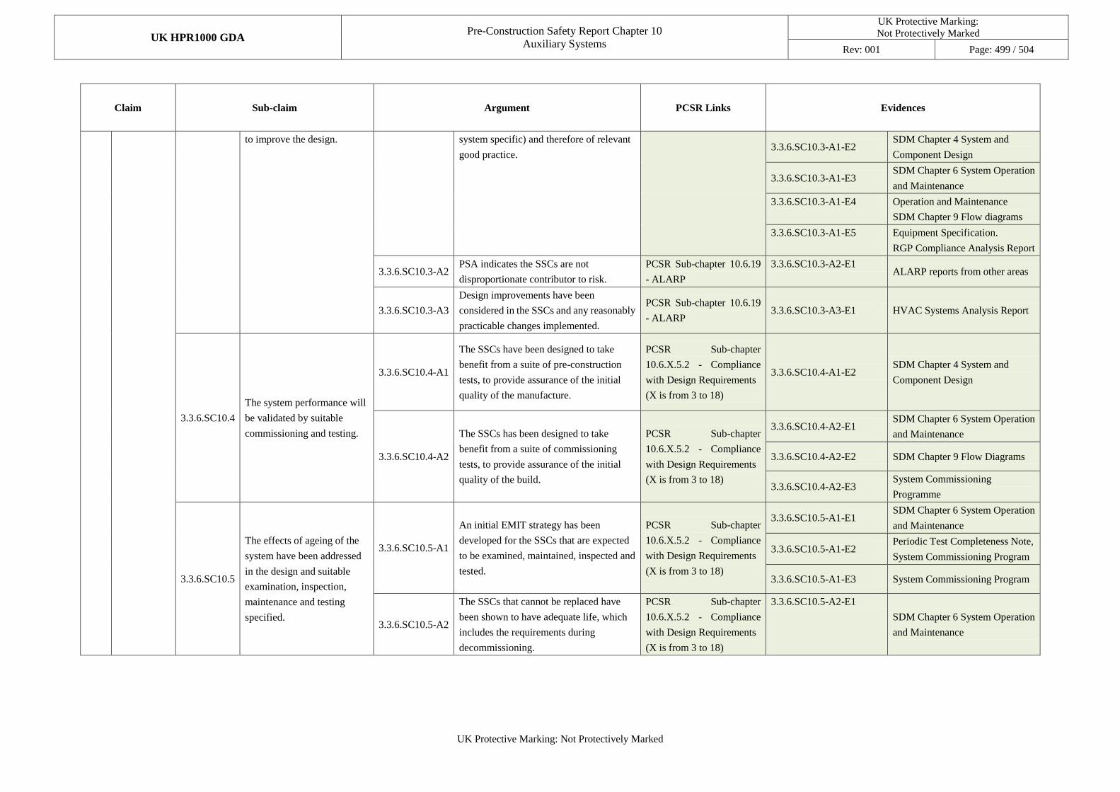
UK HPR1000 GDA Pre-Construction Safety Report Chapter 10
Auxiliary Systems
UK Protective Marking:
Not Protectively Marked
Rev: 001 Page: 499 / 504
UK Protective Marking: Not Protectively Marked
Claim Sub-claim Argument PCSR Links Evidences
to improve the design. system specific) and therefore of relevant
good practice. 3.3.6.SC10.3-A1-E2
SDM Chapter 4 System and
Component Design
3.3.6.SC10.3-A1-E3 SDM Chapter 6 System Operation
and Maintenance
3.3.6.SC10.3-A1-E4 Operation and Maintenance
SDM Chapter 9 Flow diagrams
3.3.6.SC10.3-A1-E5 Equipment Specification.
RGP Compliance Analysis Report
3.3.6.SC10.3-A2 PSA indicates the SSCs are not
disproportionate contributor to risk.
PCSR Sub-chapter 10.6.19
- ALARP
3.3.6.SC10.3-A2-E1 ALARP reports from other areas
3.3.6.SC10.3-A3
Design improvements have been
considered in the SSCs and any reasonably
practicable changes implemented.
PCSR Sub-chapter 10.6.19
- ALARP 3.3.6.SC10.3-A3-E1 HVAC Systems Analysis Report
3.3.6.SC10.4
The system performance will
be validated by suitable
commissioning and testing.
3.3.6.SC10.4-A1
The SSCs have been designed to take
benefit from a suite of pre-construction
tests, to provide assurance of the initial
quality of the manufacture.
PCSR Sub-chapter
10.6.X.5.2 - Compliance
with Design Requirements
(X is from 3 to 18)
3.3.6.SC10.4-A1-E2 SDM Chapter 4 System and
Component Design
3.3.6.SC10.4-A2
The SSCs has been designed to take
benefit from a suite of commissioning
tests, to provide assurance of the initial
quality of the build.
PCSR Sub-chapter
10.6.X.5.2 - Compliance
with Design Requirements
(X is from 3 to 18)
3.3.6.SC10.4-A2-E1 SDM Chapter 6 System Operation
and Maintenance
3.3.6.SC10.4-A2-E2 SDM Chapter 9 Flow Diagrams
3.3.6.SC10.4-A2-E3 System Commissioning
Programme
3.3.6.SC10.5
The effects of ageing of the
system have been addressed
in the design and suitable
examination, inspection,
maintenance and testing
specified.
3.3.6.SC10.5-A1
An initial EMIT strategy has been
developed for the SSCs that are expected
to be examined, maintained, inspected and
tested.
PCSR Sub-chapter
10.6.X.5.2 - Compliance
with Design Requirements
(X is from 3 to 18)
3.3.6.SC10.5-A1-E1 SDM Chapter 6 System Operation
and Maintenance
3.3.6.SC10.5-A1-E2 Periodic Test Completeness Note,
System Commissioning Program
3.3.6.SC10.5-A1-E3 System Commissioning Program
3.3.6.SC10.5-A2
The SSCs that cannot be replaced have
been shown to have adequate life, which
includes the requirements during
decommissioning.
PCSR Sub-chapter
10.6.X.5.2 - Compliance
with Design Requirements
(X is from 3 to 18)
3.3.6.SC10.5-A2-E1
SDM Chapter 6 System Operation
and Maintenance
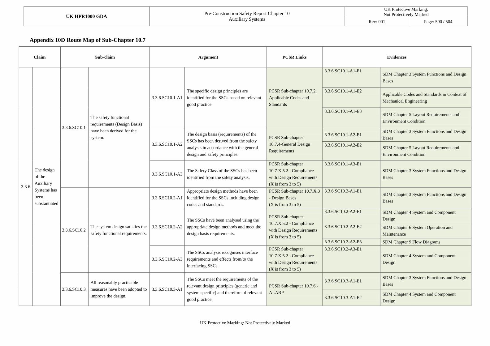
UK HPR1000 GDA Pre-Construction Safety Report Chapter 10
Auxiliary Systems
UK Protective Marking:
Not Protectively Marked
Rev: 001 Page: 500 / 504
UK Protective Marking: Not Protectively Marked
Appendix 10D Route Map of Sub-Chapter 10.7
Claim Sub-claim Argument PCSR Links Evidences
3.3.6
The design
of the
Auxiliary
Systems has
been
substantiated
3.3.6.SC10.1
The safety functional
requirements (Design Basis)
have been derived for the
system.
3.3.6.SC10.1-A1
The specific design principles are
identified for the SSCs based on relevant
good practice.
PCSR Sub-chapter 10.7.2.
Applicable Codes and
Standards
3.3.6.SC10.1-A1-E1 SDM Chapter 3 System Functions and Design
Bases
3.3.6.SC10.1-A1-E2 Applicable Codes and Standards in Context of
Mechanical Engineering
3.3.6.SC10.1-A1-E3 SDM Chapter 5 Layout Requirements and
Environment Condition
3.3.6.SC10.1-A2
The design basis (requirements) of the
SSCs has been derived from the safety
analysis in accordance with the general
design and safety principles.
PCSR Sub-chapter
10.7.4-General Design
Requirements
3.3.6.SC10.1-A2-E1 SDM Chapter 3 System Functions and Design
Bases
3.3.6.SC10.1-A2-E2 SDM Chapter 5 Layout Requirements and
Environment Condition
3.3.6.SC10.1-A3 The Safety Class of the SSCs has been
identified from the safety analysis.
PCSR Sub-chapter
10.7.X.5.2 - Compliance
with Design Requirements
(X is from 3 to 5)
3.3.6.SC10.1-A3-E1
SDM Chapter 3 System Functions and Design
Bases
3.3.6.SC10.2 The system design satisfies the
safety functional requirements.
3.3.6.SC10.2-A1
Appropriate design methods have been
identified for the SSCs including design
codes and standards.
PCSR Sub-chapter 10.7.X.3
- Design Bases
(X is from 3 to 5)
3.3.6.SC10.2-A1-E1 SDM Chapter 3 System Functions and Design
Bases
3.3.6.SC10.2-A2
The SSCs have been analysed using the
appropriate design methods and meet the
design basis requirements.
PCSR Sub-chapter
10.7.X.5.2 - Compliance
with Design Requirements
(X is from 3 to 5)
3.3.6.SC10.2-A2-E1 SDM Chapter 4 System and Component
Design
3.3.6.SC10.2-A2-E2 SDM Chapter 6 System Operation and
Maintenance
3.3.6.SC10.2-A2-E3 SDM Chapter 9 Flow Diagrams
3.3.6.SC10.2-A3
The SSCs analysis recognises interface
requirements and effects from/to the
interfacing SSCs.
PCSR Sub-chapter
10.7.X.5.2 - Compliance
with Design Requirements
(X is from 3 to 5)
3.3.6.SC10.2-A3-E1
SDM Chapter 4 System and Component
Design
3.3.6.SC10.3
All reasonably practicable
measures have been adopted to
improve the design.
3.3.6.SC10.3-A1
The SSCs meet the requirements of the
relevant design principles (generic and
system specific) and therefore of relevant
good practice.
PCSR Sub-chapter 10.7.6 -
ALARP
3.3.6.SC10.3-A1-E1 SDM Chapter 3 System Functions and Design
Bases
3.3.6.SC10.3-A1-E2 SDM Chapter 4 System and Component
Design
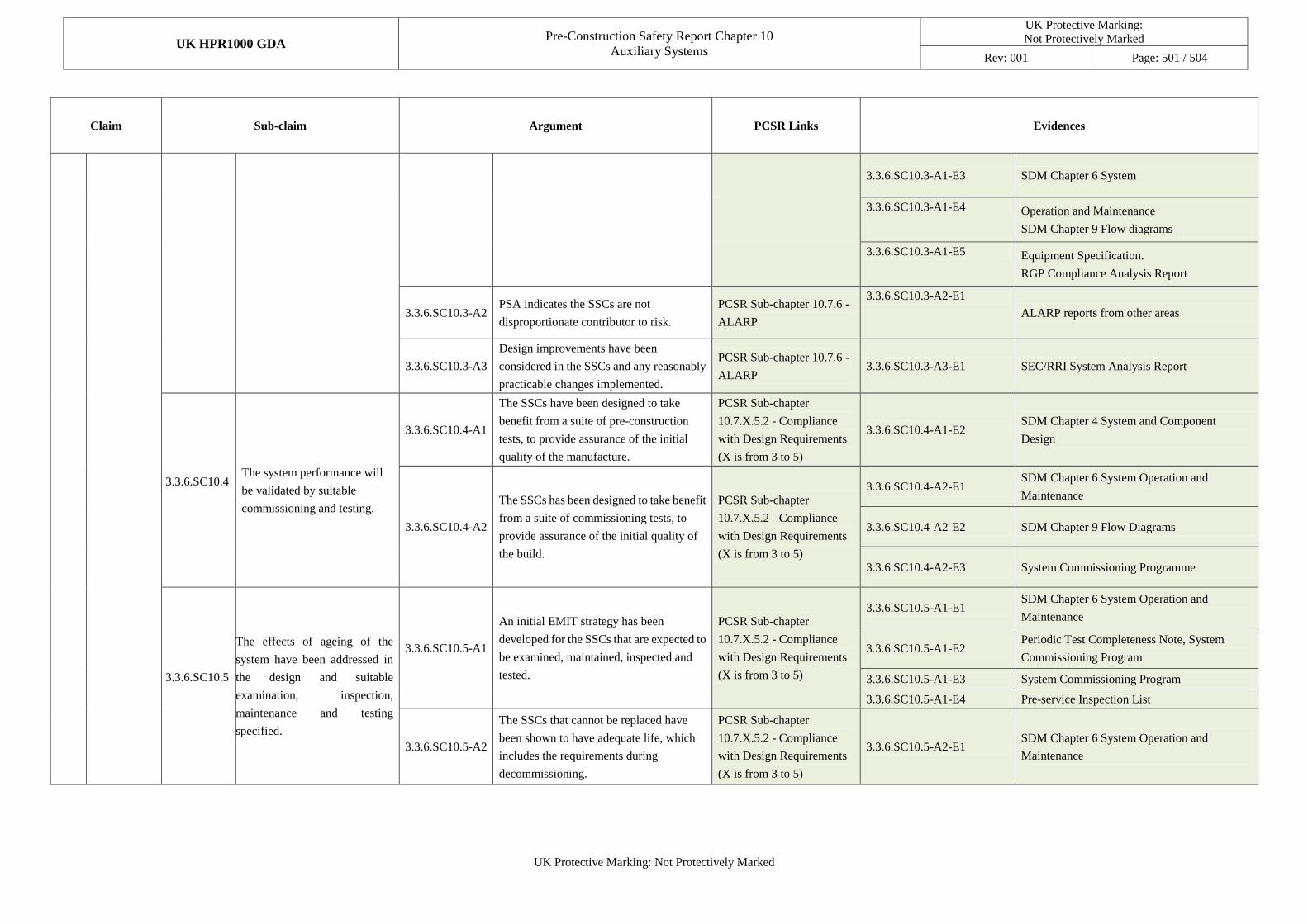
UK HPR1000 GDA Pre-Construction Safety Report Chapter 10
Auxiliary Systems
UK Protective Marking:
Not Protectively Marked
Rev: 001 Page: 501 / 504
UK Protective Marking: Not Protectively Marked
Claim Sub-claim Argument PCSR Links Evidences
3.3.6.SC10.3-A1-E3 SDM Chapter 6 System
3.3.6.SC10.3-A1-E4 Operation and Maintenance
SDM Chapter 9 Flow diagrams
3.3.6.SC10.3-A1-E5 Equipment Specification.
RGP Compliance Analysis Report
3.3.6.SC10.3-A2 PSA indicates the SSCs are not
disproportionate contributor to risk.
PCSR Sub-chapter 10.7.6 -
ALARP
3.3.6.SC10.3-A2-E1
ALARP reports from other areas
3.3.6.SC10.3-A3
Design improvements have been
considered in the SSCs and any reasonably
practicable changes implemented.
PCSR Sub-chapter 10.7.6 -
ALARP 3.3.6.SC10.3-A3-E1 SEC/RRI System Analysis Report
3.3.6.SC10.4
The system performance will
be validated by suitable
commissioning and testing.
3.3.6.SC10.4-A1
The SSCs have been designed to take
benefit from a suite of pre-construction
tests, to provide assurance of the initial
quality of the manufacture.
PCSR Sub-chapter
10.7.X.5.2 - Compliance
with Design Requirements
(X is from 3 to 5)
3.3.6.SC10.4-A1-E2 SDM Chapter 4 System and Component
Design
3.3.6.SC10.4-A2
The SSCs has been designed to take benefit
from a suite of commissioning tests, to
provide assurance of the initial quality of
the build.
PCSR Sub-chapter
10.7.X.5.2 - Compliance
with Design Requirements
(X is from 3 to 5)
3.3.6.SC10.4-A2-E1 SDM Chapter 6 System Operation and
Maintenance
3.3.6.SC10.4-A2-E2 SDM Chapter 9 Flow Diagrams
3.3.6.SC10.4-A2-E3 System Commissioning Programme
3.3.6.SC10.5
The effects of ageing of the
system have been addressed in
the design and suitable
examination, inspection,
maintenance and testing
specified.
3.3.6.SC10.5-A1
An initial EMIT strategy has been
developed for the SSCs that are expected to
be examined, maintained, inspected and
tested.
PCSR Sub-chapter
10.7.X.5.2 - Compliance
with Design Requirements
(X is from 3 to 5)
3.3.6.SC10.5-A1-E1 SDM Chapter 6 System Operation and
Maintenance
3.3.6.SC10.5-A1-E2 Periodic Test Completeness Note, System
Commissioning Program
3.3.6.SC10.5-A1-E3 System Commissioning Program
3.3.6.SC10.5-A1-E4 Pre-service Inspection List
3.3.6.SC10.5-A2
The SSCs that cannot be replaced have
been shown to have adequate life, which
includes the requirements during
decommissioning.
PCSR Sub-chapter
10.7.X.5.2 - Compliance
with Design Requirements
(X is from 3 to 5)
3.3.6.SC10.5-A2-E1 SDM Chapter 6 System Operation and
Maintenance
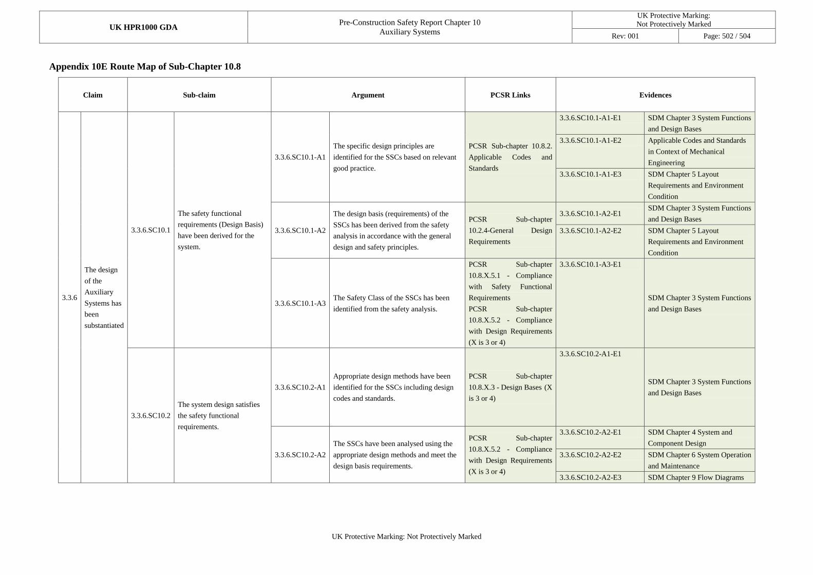
UK HPR1000 GDA Pre-Construction Safety Report Chapter 10
Auxiliary Systems
UK Protective Marking:
Not Protectively Marked
Rev: 001 Page: 502 / 504
UK Protective Marking: Not Protectively Marked
Appendix 10E Route Map of Sub-Chapter 10.8
Claim Sub-claim Argument PCSR Links Evidences
3.3.6
The design
of the
Auxiliary
Systems has
been
substantiated
3.3.6.SC10.1
The safety functional
requirements (Design Basis)
have been derived for the
system.
3.3.6.SC10.1-A1
The specific design principles are
identified for the SSCs based on relevant
good practice.
PCSR Sub-chapter 10.8.2.
Applicable Codes and
Standards
3.3.6.SC10.1-A1-E1 SDM Chapter 3 System Functions
and Design Bases
3.3.6.SC10.1-A1-E2 Applicable Codes and Standards
in Context of Mechanical
Engineering
3.3.6.SC10.1-A1-E3 SDM Chapter 5 Layout
Requirements and Environment
Condition
3.3.6.SC10.1-A2
The design basis (requirements) of the
SSCs has been derived from the safety
analysis in accordance with the general
design and safety principles.
PCSR Sub-chapter
10.2.4-General Design
Requirements
3.3.6.SC10.1-A2-E1 SDM Chapter 3 System Functions
and Design Bases
3.3.6.SC10.1-A2-E2 SDM Chapter 5 Layout
Requirements and Environment
Condition
3.3.6.SC10.1-A3 The Safety Class of the SSCs has been
identified from the safety analysis.
PCSR Sub-chapter
10.8.X.5.1 - Compliance
with Safety Functional
Requirements
PCSR Sub-chapter
10.8.X.5.2 - Compliance
with Design Requirements
(X is 3 or 4)
3.3.6.SC10.1-A3-E1
SDM Chapter 3 System Functions
and Design Bases
3.3.6.SC10.2
The system design satisfies
the safety functional
requirements.
3.3.6.SC10.2-A1
Appropriate design methods have been
identified for the SSCs including design
codes and standards.
PCSR Sub-chapter
10.8.X.3 - Design Bases (X
is 3 or 4)
3.3.6.SC10.2-A1-E1
SDM Chapter 3 System Functions
and Design Bases
3.3.6.SC10.2-A2
The SSCs have been analysed using the
appropriate design methods and meet the
design basis requirements.
PCSR Sub-chapter
10.8.X.5.2 - Compliance
with Design Requirements
(X is 3 or 4)
3.3.6.SC10.2-A2-E1 SDM Chapter 4 System and
Component Design
3.3.6.SC10.2-A2-E2 SDM Chapter 6 System Operation
and Maintenance
3.3.6.SC10.2-A2-E3 SDM Chapter 9 Flow Diagrams
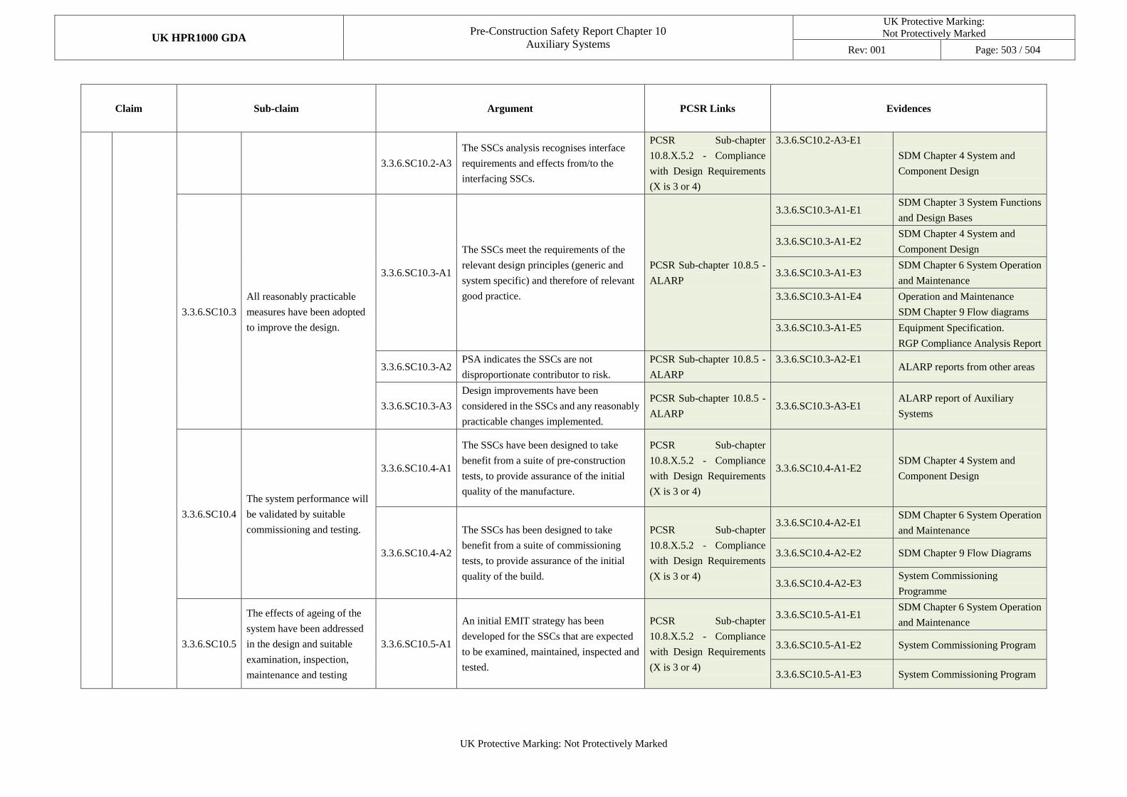
UK HPR1000 GDA Pre-Construction Safety Report Chapter 10
Auxiliary Systems
UK Protective Marking:
Not Protectively Marked
Rev: 001 Page: 503 / 504
UK Protective Marking: Not Protectively Marked
Claim Sub-claim Argument PCSR Links Evidences
3.3.6.SC10.2-A3
The SSCs analysis recognises interface
requirements and effects from/to the
interfacing SSCs.
PCSR Sub-chapter
10.8.X.5.2 - Compliance
with Design Requirements
(X is 3 or 4)
3.3.6.SC10.2-A3-E1
SDM Chapter 4 System and
Component Design
3.3.6.SC10.3
All reasonably practicable
measures have been adopted
to improve the design.
3.3.6.SC10.3-A1
The SSCs meet the requirements of the
relevant design principles (generic and
system specific) and therefore of relevant
good practice.
PCSR Sub-chapter 10.8.5 -
ALARP
3.3.6.SC10.3-A1-E1 SDM Chapter 3 System Functions
and Design Bases
3.3.6.SC10.3-A1-E2 SDM Chapter 4 System and
Component Design
3.3.6.SC10.3-A1-E3 SDM Chapter 6 System Operation
and Maintenance
3.3.6.SC10.3-A1-E4 Operation and Maintenance
SDM Chapter 9 Flow diagrams
3.3.6.SC10.3-A1-E5 Equipment Specification.
RGP Compliance Analysis Report
3.3.6.SC10.3-A2 PSA indicates the SSCs are not
disproportionate contributor to risk.
PCSR Sub-chapter 10.8.5 -
ALARP
3.3.6.SC10.3-A2-E1 ALARP reports from other areas
3.3.6.SC10.3-A3
Design improvements have been
considered in the SSCs and any reasonably
practicable changes implemented.
PCSR Sub-chapter 10.8.5 -
ALARP 3.3.6.SC10.3-A3-E1
ALARP report of Auxiliary
Systems
3.3.6.SC10.4
The system performance will
be validated by suitable
commissioning and testing.
3.3.6.SC10.4-A1
The SSCs have been designed to take
benefit from a suite of pre-construction
tests, to provide assurance of the initial
quality of the manufacture.
PCSR Sub-chapter
10.8.X.5.2 - Compliance
with Design Requirements
(X is 3 or 4)
3.3.6.SC10.4-A1-E2 SDM Chapter 4 System and
Component Design
3.3.6.SC10.4-A2
The SSCs has been designed to take
benefit from a suite of commissioning
tests, to provide assurance of the initial
quality of the build.
PCSR Sub-chapter
10.8.X.5.2 - Compliance
with Design Requirements
(X is 3 or 4)
3.3.6.SC10.4-A2-E1 SDM Chapter 6 System Operation
and Maintenance
3.3.6.SC10.4-A2-E2 SDM Chapter 9 Flow Diagrams
3.3.6.SC10.4-A2-E3 System Commissioning
Programme
3.3.6.SC10.5
The effects of ageing of the
system have been addressed
in the design and suitable
examination, inspection,
maintenance and testing
3.3.6.SC10.5-A1
An initial EMIT strategy has been
developed for the SSCs that are expected
to be examined, maintained, inspected and
tested.
PCSR Sub-chapter
10.8.X.5.2 - Compliance
with Design Requirements
(X is 3 or 4)
3.3.6.SC10.5-A1-E1 SDM Chapter 6 System Operation
and Maintenance
3.3.6.SC10.5-A1-E2 System Commissioning Program
3.3.6.SC10.5-A1-E3 System Commissioning Program
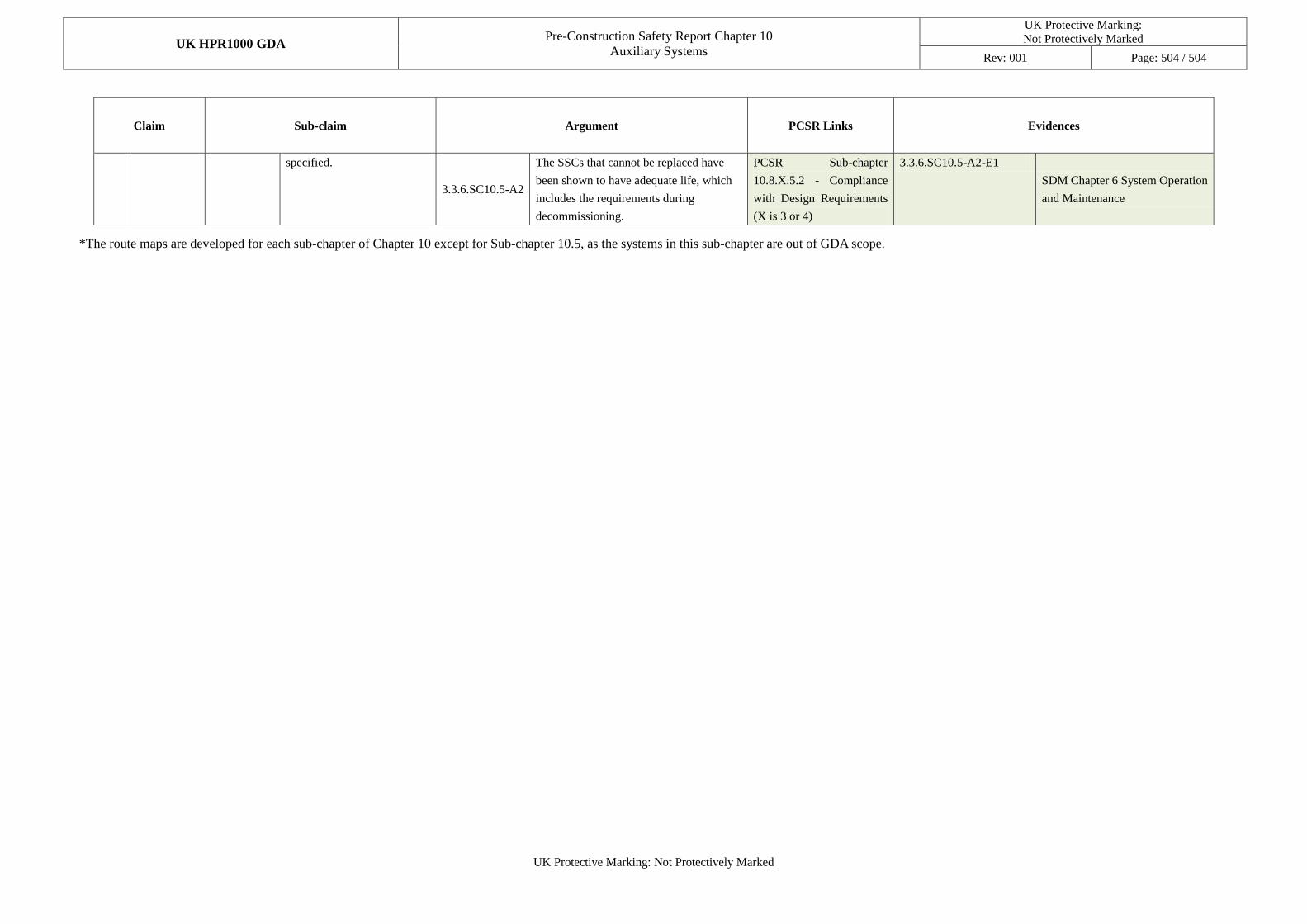
UK HPR1000 GDA Pre-Construction Safety Report Chapter 10
Auxiliary Systems
UK Protective Marking:
Not Protectively Marked
Rev: 001 Page: 504 / 504
UK Protective Marking: Not Protectively Marked
Claim Sub-claim Argument PCSR Links Evidences
specified.
3.3.6.SC10.5-A2
The SSCs that cannot be replaced have
been shown to have adequate life, which
includes the requirements during
decommissioning.
PCSR Sub-chapter
10.8.X.5.2 - Compliance
with Design Requirements
(X is 3 or 4)
3.3.6.SC10.5-A2-E1
SDM Chapter 6 System Operation
and Maintenance
*The route maps are developed for each sub-chapter of Chapter 10 except for Sub-chapter 10.5, as the systems in this sub-chapter are out of GDA scope.


![UK Protective Marking: UK HPR1000€¦ · [FBHE]). 10.2 Introduction 10.2.1 Overview The Hua-long Pressurised Reactor (HPR1000) operating in China is designed according to the domestic](https://img.pdfslide.us/doc/110x75/5ea2bdb9e57f3937f37f934d/uk-protective-marking-uk-fbhe-102-introduction-1021-overview-the-hua-long.jpg)