Embed Size (px)
Citation preview
Return-to-Zero Measurement Methodologies For 10 and 40 Gb/s Waveforms

Return-to-zero Measurement MethodologiesFor 10 and 40 Gb/s Waveforms
6 -1
Return-to-zero Measurement Methodologies for 10 to 40 Gb/s Waveforms
As communications speeds increase, and transmission distances expand, return to zero (RZ) modulation formats will gain in popularity. This paper will discuss a variety of measurements that can be made with a high-speed sampling oscilloscope to characterize the RZ waveform.

Return-to-zero Measurement MethodologiesFor 10 and 40 Gb/s Waveforms
6 -2
Introduction and Outline
• What is an “RZ” signal and why is it used?• Properties of RZ signals that can be
determined through waveform characterization
• Detailed discussion on jitter, extinction ratio, contrast ratio, and eye masks
• Oscilloscope hardware requirements for 40 Gb/s analysis
In this paper we will first discuss what an RZ signal is in comparison to the more common non-return-to-zero format. We will then discuss some of the reasons that RZ signals are used. The discussion will then focus on specific parameters that can be measured on the RZ signal with the oscilloscope. A specific emphasis will be placed on the measurement of extinction ratio, contrast ratio, and jitter in that these tests vary significantly from their NRZ counterparts. Finally, there will be a short review of recent improvements in oscilloscope hardware specifically made to improve measurement performance for 40 Gb/s signals.

Return-to-zero Measurement MethodologiesFor 10 and 40 Gb/s Waveforms
6 -3
What Is an “RZ” Signal?
• NRZ (non-return to zero) signals have dominated optical communications
• For RZ, logical ‘1’s always begin and end at the low power state or “return to zero”
• RZ signals are more difficult to produce and require more signal bandwidth
The difference between an NRZ and RZ signal is somewhat self-explanatory. The RZ signal transmission of a logic ‘1’ will always begin at zero and end at zero. The lower of the two diagrams shown is of the RZ eye diagram. It is a composition of several transmitted 1’s and 0’s overlaid on top of each other in a single display. Note how all ‘1’ pulses, whether they are preceded by and followed by a 1 or a 0, start and end at the low power state.
In contrast, the NRZ diagram (top display) shows how a ‘1’ will stay at the high level if the preceding bit is a 1.

Return-to-zero Measurement MethodologiesFor 10 and 40 Gb/s Waveforms
6 -4
Why does the RZ signal require more bandwidth than the NRZ signal?
• Consider two 10101010 bitstreams, one NRZ, the other RZ
• The data rate for each is 1 Gb/s
• The fundamental frequency for the NRZ signal is 500 MHz, spectrum follows a sinx/x envelope with the first null at 1000 MHz (odd harmonics only at 1500, 2500, 3500 …MHz
• The fundamental frequency for the RZ signal is also 500 MHz, spectrum follows a sinx/x envelope with the first null at 2000 MHz. Harmonics at 1000, 1500, 2500 …MHz
1 0 1 0 1 0 1
1 0 1 0 1 0 1
RZ signals require more bandwidth than NRZ signals. Intuitively this is clear when considering that the RZ signal is switching twice as often as the NRZ signal. Another approach is to compute the spectrum for each signal type for a specific bit stream. A simple case is the alternating stream of 1’s and 0’s. In the case of the 1 Gb/s NRZ signal, the spectrum for a 1-0-1-0-1-0-1-0… bit stream is approximated by the 500 MHz square wave. This signal will have spectral elements at the odd harmonics of 500 MHz. The general shape of the spectrum is the sinx/x function with nulls at the even harmonics.
For the RZ signal at 1 Gb/s, the pulse duration for ‘1’s must be significantly narrower than the NRZ signal. If we say that the pulse width is 50% of a bit period, then this signal is approximated by a 500 MHz pulse train. It is similar to the NRZ signal, except that instead of a 50% duty cycle, the signal has a 25% duty cycle.
Once again, the spectrum is defined by a sin x/x function. In this case, the frequency nulls are at the fourth, eight, twelfth and so on harmonics of 500 MHz. Thus in this simple example, the RZ signal requires approximately double the bandwidth of the NRZ signal.
Return-to-zero Measurement MethodologiesFor 10 and 40 Gb/s Waveforms
6 -5
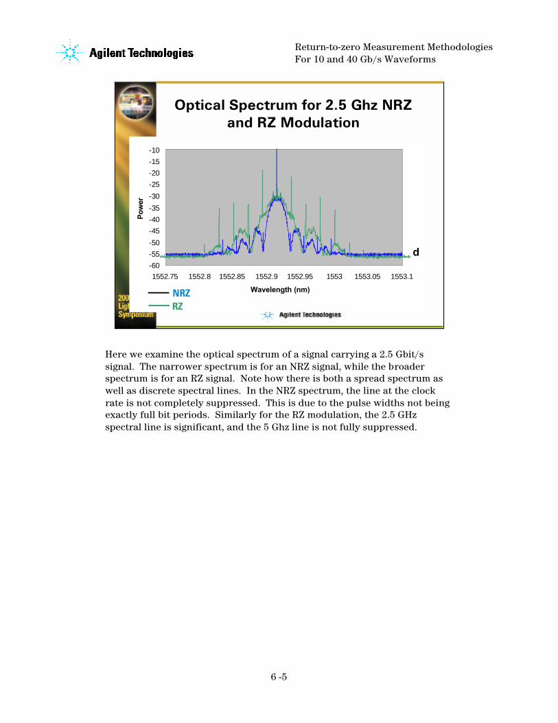
Optical Spectrum for 2.5 Ghz NRZ and RZ Modulation
-60
-55
-50
-45
-40
-35
-30
-25
-20
-15
-10
1552.75 1552.8 1552.85 1552.9 1552.95 1553 1553.05 1553.1
Wavelength (nm)
Po
wer
NRZRZ
d
Here we examine the optical spectrum of a signal carrying a 2.5 Gbit/s signal. The narrower spectrum is for an NRZ signal, while the broader spectrum is for an RZ signal. Note how there is both a spread spectrum as well as discrete spectral lines. In the NRZ spectrum, the line at the clock rate is not completely suppressed. This is due to the pulse widths not being exactly full bit periods. Similarly for the RZ modulation, the 2.5 GHz spectral line is significant, and the 5 Ghz line is not fully suppressed.
Return-to-zero Measurement MethodologiesFor 10 and 40 Gb/s Waveforms
6 -6
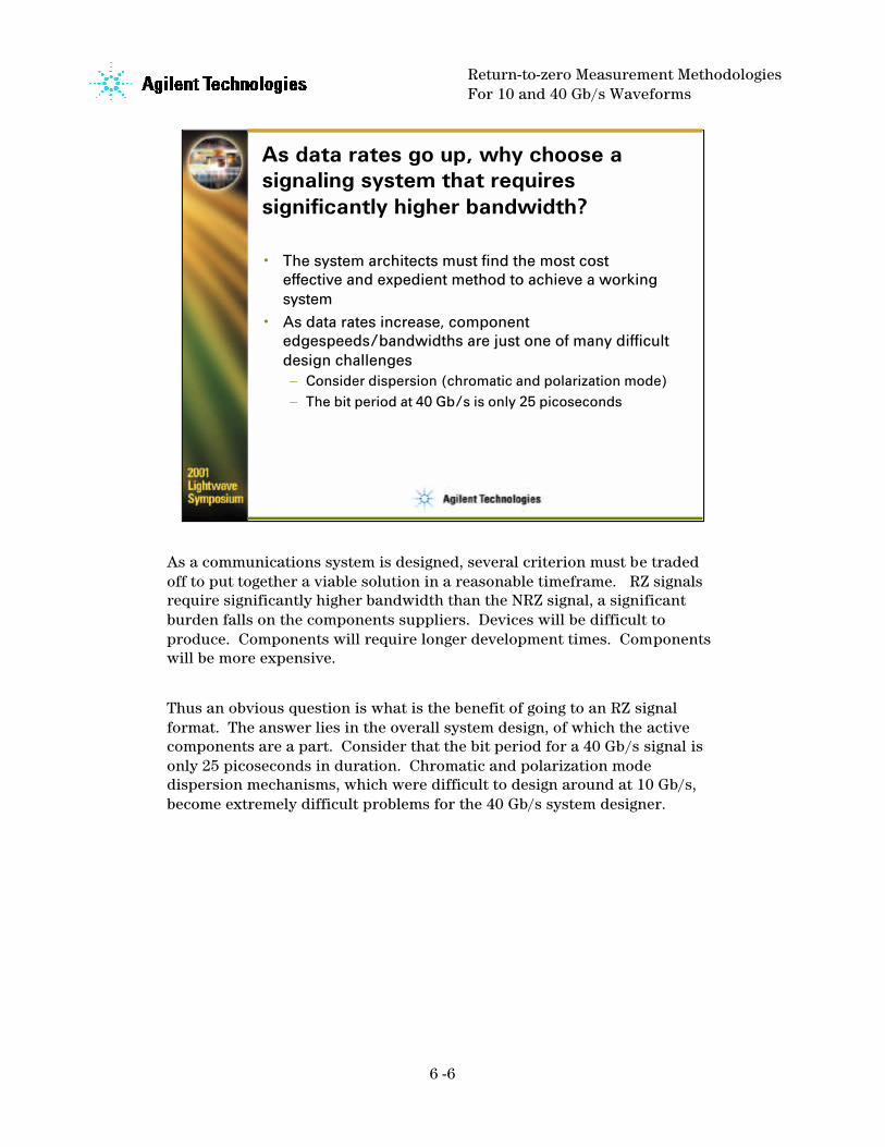
As data rates go up, why choose a signaling system that requires significantly higher bandwidth?
• The system architects must find the most cost effective and expedient method to achieve a working system
• As data rates increase, component edgespeeds/bandwidths are just one of many difficult design challenges– Consider dispersion (chromatic and polarization mode)– The bit period at 40 Gb/s is only 25 picoseconds
As a communications system is designed, several criterion must be traded off to put together a viable solution in a reasonable timeframe. RZ signals require significantly higher bandwidth than the NRZ signal, a significant burden falls on the components suppliers. Devices will be difficult to produce. Components will require longer development times. Components will be more expensive.
Thus an obvious question is what is the benefit of going to an RZ signal format. The answer lies in the overall system design, of which the active components are a part. Consider that the bit period for a 40 Gb/s signal is only 25 picoseconds in duration. Chromatic and polarization mode dispersion mechanisms, which were difficult to design around at 10 Gb/s, become extremely difficult problems for the 40 Gb/s system designer.

Return-to-zero Measurement MethodologiesFor 10 and 40 Gb/s Waveforms
6 -7
The system architect may determine that although it is costly and difficult to build RZ compatible components, other challenges are effectively overcome
• Dispersion is less likely to cause an RZ pulse to interfere with successive pulses in a bitstream
• Solitons, a type of RZ signal, can take advantage of fiber nonlinearity to counteract the effects of dispersion
• Reduced low frequency spectral content• Strong spectral content at line rate simplifies
clock recovery
The RZ signal provides some relief to these problems. In a very simple sense, for a given amount of dispersion the narrower pulses of the RZ system are less likely to drift into adjacent pulses and cause inter-symbol interference degradation. Also, depending upon the shape and power of RZ pulses, there is some dispersion mitigation through the soliton effect.
Return-to-zero Measurement MethodologiesFor 10 and 40 Gb/s Waveforms
6 -8
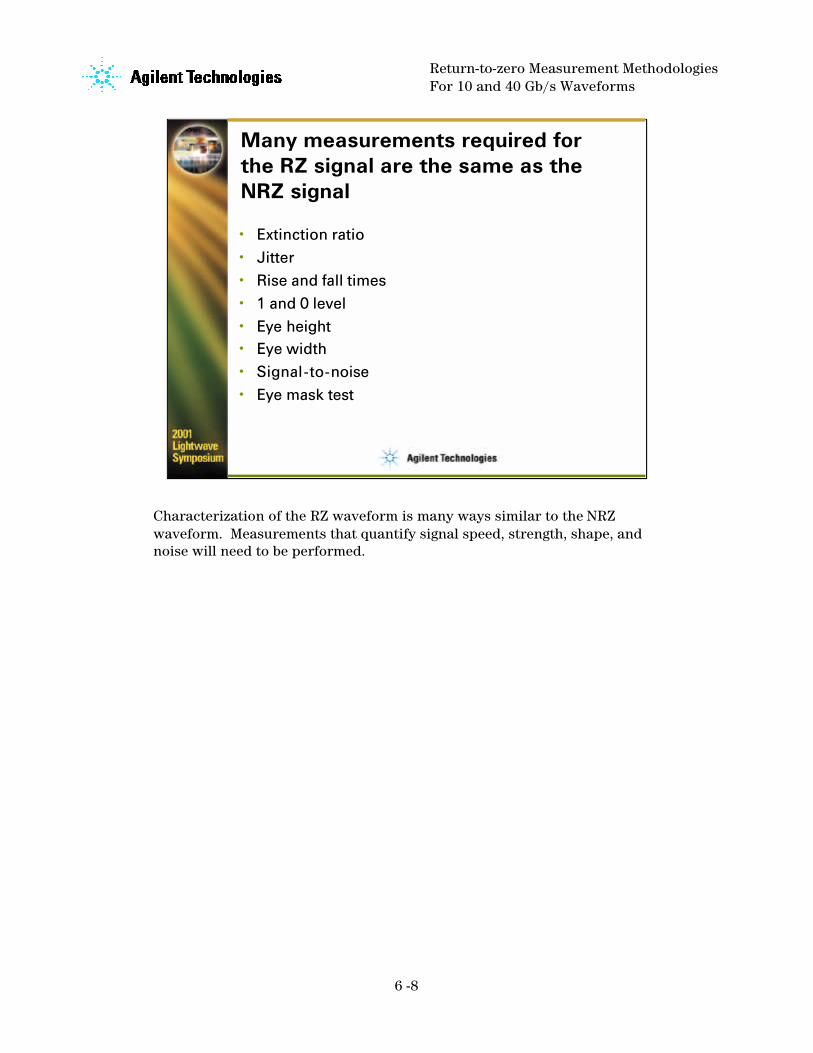
Many measurements required for the RZ signal are the same as the NRZ signal
• Extinction ratio• Jitter• Rise and fall times• 1 and 0 level• Eye height• Eye width• Signal-to-noise• Eye mask test
Characterization of the RZ waveform is many ways similar to the NRZ waveform. Measurements that quantify signal speed, strength, shape, and noise will need to be performed.

Return-to-zero Measurement MethodologiesFor 10 and 40 Gb/s Waveforms
6 -9
Some measurements useful for RZ are not valid for the NRZ signal
• Contrast ratio• Pulsewidth• Duty cycle
In addition to measurements that are common to both the NRZ and RZ signal, RZ waveform characterization will also have three other measurements. A “new” measurement, contrast ratio, will be described in detail later.
Return-to-zero Measurement MethodologiesFor 10 and 40 Gb/s Waveforms
6 -10
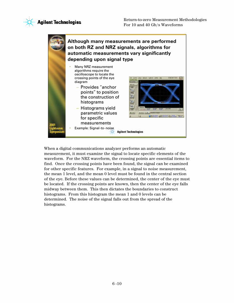
Although many measurements are performed on both RZ and NRZ signals, algorithms for automatic measurements vary significantly depending upon signal type
• Many NRZ measurement algorithms require the oscilloscope to locate the crossing points of the eye diagram– Provides “anchor
points” to position the construction of histograms
– Histograms yield parametric values for specific measurements
• Example: Signal-to-noise
When a digital communications analyzer performs an automatic measurement, it must examine the signal to locate specific elements of the waveform. For the NRZ waveform, the crossing points are essential items to find. Once the crossing points have been found, the signal can be examined for other specific features. For example, in a signal to noise measurement, the mean 1 level, and the mean 0 level must be found in the central section of the eye. Before these values can be determined, the center of the eye must be located. If the crossing points are known, then the center of the eye falls midway between them. This then dictates the boundaries to construct histograms. From this histogram the mean 1 and 0 levels can be determined. The noise of the signal falls out from the spread of the histograms.
Return-to-zero Measurement MethodologiesFor 10 and 40 Gb/s Waveforms
6 -11
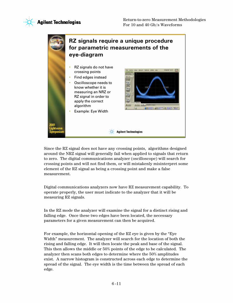
RZ signals require a unique procedure for parametric measurements of the eye-diagram
• RZ signals do not have crossing points
• Find edges instead• Oscilloscope needs to
know whether it is measuring an NRZ or RZ signal in order to apply the correct algorithm
• Example: Eye Width
Since the RZ signal does not have any crossing points, algorithms designed around the NRZ signal will generally fail when applied to signals that return to zero. The digital communications analyzer (oscilloscope) will search for crossing points and will not find them, or will mistakenly misinterpret some element of the RZ signal as being a crossing point and make a false measurement.
Digital communications analyzers now have RZ measurement capability. To operate properly, the user must indicate to the analyzer that it will be measuring RZ signals.
In the RZ mode the analyzer will examine the signal for a distinct rising and falling edge. Once these two edges have been located, the necessary parameters for a given measurement can then be acquired.
For example, the horizontal opening of the RZ eye is given by the “Eye Width” measurement. The analyzer will search for the location of both the rising and falling edge. It will then locate the peak and base of the signal. This then allows the middle or 50% points of the edge to be calculated. The analyzer then scans both edges to determine where the 50% amplitudes exist. A narrow histogram is constructed across each edge to determine the spread of the signal. The eye width is the time between the spread of each edge.
Return-to-zero Measurement MethodologiesFor 10 and 40 Gb/s Waveforms
6 -12
A detailed analysis of three important RZ eye-diagram measurements
• Extinction ratio• Contrast Ratio• Jitter
Three very important measurements for the RZ signal are extinction ratio, contrast ratio, and jitter. For the RZ signal, extinction ratio and jitter are significantly different than the NRZ measurement. Contrast ratio is unique to the RZ signal.
Return-to-zero Measurement MethodologiesFor 10 and 40 Gb/s Waveforms
6 -13
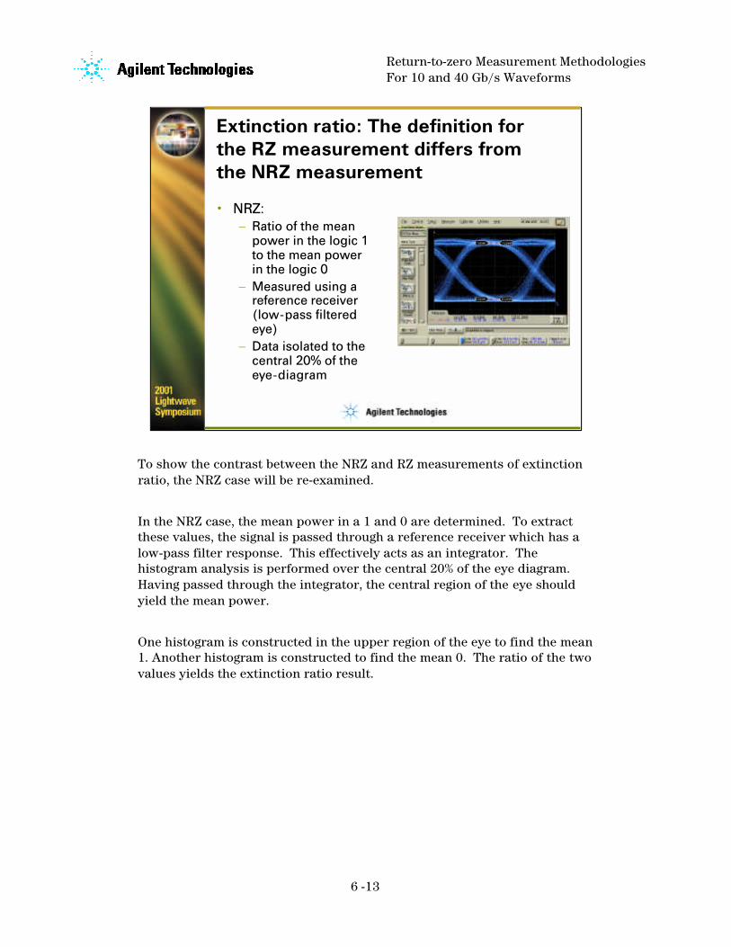
Extinction ratio: The definition for the RZ measurement differs from the NRZ measurement
• NRZ:– Ratio of the mean
power in the logic 1 to the mean power in the logic 0
– Measured using a reference receiver (low-pass filtered eye)
– Data isolated to the central 20% of the eye-diagram
To show the contrast between the NRZ and RZ measurements of extinction ratio, the NRZ case will be re-examined.
In the NRZ case, the mean power in a 1 and 0 are determined. To extract these values, the signal is passed through a reference receiver which has a low-pass filter response. This effectively acts as an integrator. The histogram analysis is performed over the central 20% of the eye diagram. Having passed through the integrator, the central region of the eye should yield the mean power.
One histogram is constructed in the upper region of the eye to find the mean 1. Another histogram is constructed to find the mean 0. The ratio of the two values yields the extinction ratio result.

Return-to-zero Measurement MethodologiesFor 10 and 40 Gb/s Waveforms
6 -14
Extinction Ratio for the RZ Signal
• RZ extinction ratio:– Ratio of the
mean power in the peak of the logic 1 to the mean power of the logic 0
– A reference receiver is not currently used
– A very narrow data slice is used
The NRZ measurement process does not apply to the RZ signal. First of all, due to the much shorter pulse duration of the RZ ‘1’, the “mean” power in a logic 1 will have a value that is somewhere close to half the amplitude of the signal. Currently, no standard reference receiver is used in the measurement thus no integration function is achieved.
Given these two constraints, the definition of extinction ratio for the RZ signal is modified from the NRZ definition. First, the 1 level is defined as the mean power in the peak of the signal as opposed to the mean power of the entire pulse. Second, to achieve this, data contributing to the histogram analysis is restricted to a very narrow region of the signal. This is typically set to the central 5% of the eye diagram.
Return-to-zero Measurement MethodologiesFor 10 and 40 Gb/s Waveforms
6 -15
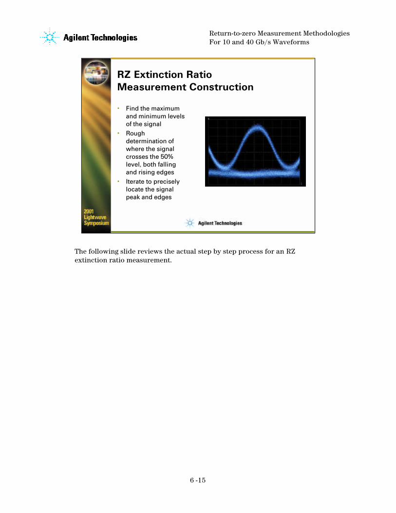
RZ Extinction Ratio Measurement Construction
• Find the maximum and minimum levels of the signal
• Rough determination of where the signal crosses the 50% level, both falling and rising edges
• Iterate to precisely locate the signal peak and edges
The following slide reviews the actual step by step process for an RZ extinction ratio measurement.

Return-to-zero Measurement MethodologiesFor 10 and 40 Gb/s Waveforms
6 -16
RZ Eye Extinction Ratio Measurement Construction
• Construct a vertical window midway between the rising and falling edges (typically 5% of the bit period in width)
• Construct a histogram using data from the upper half of the window
– Mean value yields the ‘1’ level
• Construct a histogram using data from the lower half of the window
– Mean value yields the ‘0’ level
• Extinction ratio:
– (1-dark)/(0-dark)
The diagrams show the histograms from which the critical data is obtained. (These are shown for explanatory reasons. In actual measurements the histograms are not visible on the screen unless set up manually). For the highest measurements accuracy, the dark level must be determined (through a calibration) and removed from the measurement result.

Return-to-zero Measurement MethodologiesFor 10 and 40 Gb/s Waveforms
6 -17
Contrast ratio: A new measurement specific to RZ eye-diagrams
• Defined as the ratio of the logic 1 level at the signal peak to the logic 1 level between peaks
• Used to determine how well pulses actually return to zero
• Helpful in assessing the shape of the 1 pulses
Contrast ratio is a new measurement unique to the RZ signal. Ideally a logic ‘1’ pulse should begin at a zero power level, rise up to the peak power of the signal, and then return to zero power. In this ideal case, the ratio of the peak of the ‘1’ pulse to the ‘1’ level at its lowest power would be infinite.
Like the NRZ signal where ‘0’ levels never reach a zero power lepulses do not become completely extinguished. Thus the contrast ratio will have a finite value.

Return-to-zero Measurement MethodologiesFor 10 and 40 Gb/s Waveforms
6 -18
Contrast Ratio Measurement Construction
• Use a procedure similar to extinction ratio to locate and determine the mean 1 level at the peak of the pulse and the 0 level
• Re-position the histogram window between pulses to determine signal level of the 1– How can the 1
level be differentiated from the 0 level?
The procedure for measuring contrast ratio is quite similar to the extinction ratio measurement. However, there is one significant problem that occurs when the ‘1’ level in the “off” state is determined. In this region, the waveform is composed of both the minimal ‘1’ level as well as the signal from a 0 leading to another 0. Yet the contrast ratio should be independent of the 0 signal contribution.
Observe the histogram constructed in the region of the minimum 1. The mean of this histogram would clearly be heavily influenced by the 0 signal. The mean of the histogram would not be indicative of the minimum level of the 1. Instead it would yield a number significantly lower and a contrast ratio that was much higher than the true value.
To deal with this problem, the contribution of the 0 is determined and mathematically removed. The 0 level is measured in the center of the eye. It is then assumed that the 0 level does not change significantly and will have the same energy in the region where the 1 pulse returns to zero. Thus the analyzer will de-embed the 0 contribution form the overall histogram.
Of course if the 0 signal changes, the above assumptions are invalid and there will be an increased measurement uncertainty.

Return-to-zero Measurement MethodologiesFor 10 and 40 Gb/s Waveforms
6 -19
Isolating the Extinguished 1 Level From the 0 Level
• Assume the ‘0’ level is consistent from the middle of the bit to the area between bits
• Measure the ‘0’ level in the center of the eye
• Mathematically remove it from the aggregate histogram (1 and 0 signal combination) between bits
• Contrast ratio: (mean 1 at peak -dark)/(adjusted mean at pit -dark)
This slide shows how the 0 level is determined and used in the overall construction of the contrast ratio measurement.

Return-to-zero Measurement MethodologiesFor 10 and 40 Gb/s Waveforms
6 -20
Jitter Measurements on RZ Eye Diagrams
• Jitter: Compare with the jitter measurement of the NRZ eye:
– A histogram constructed at the NRZ crossing point will contain the jitter from both the rising and falling edges
– Due to symmetry of two adjacent NRZ eyes, single crossing point measurements should represent total eye closure due to jitter
The procedure for jitter measurements of the RZ eye must also deviate from the NRZ case.
Consider how jitter is measured on the NRZ eye. It is typical to measure this value at the crossing point of the eye diagram. A very thin histogram is constructed across the crossing point. One component of the spread of the histogram will be from the variance (jitter) in the location of the falling edges of the eye diagram. This can be due to both random and deterministic jitter. Another component of the spread will be from both random and deterministic jitter on the rising edges of the eye.
The spread of the histogram will yield the total jitter. It is interesting to note that it does not matter which crossing point is selected for the measurement. If the eye diagram has been acquired by triggering the oscilloscope with a clock trigger, each eye diagram is essentially a replication of any other.
Eye closure is due to the both rising and falling edges. Due to the symmetry of eye diagrams, measuring the jitter on one full crossing point effectively yields the amount of eye closure for both the left and right sides of the eye.
Return-to-zero Measurement MethodologiesFor 10 and 40 Gb/s Waveforms
6 -21
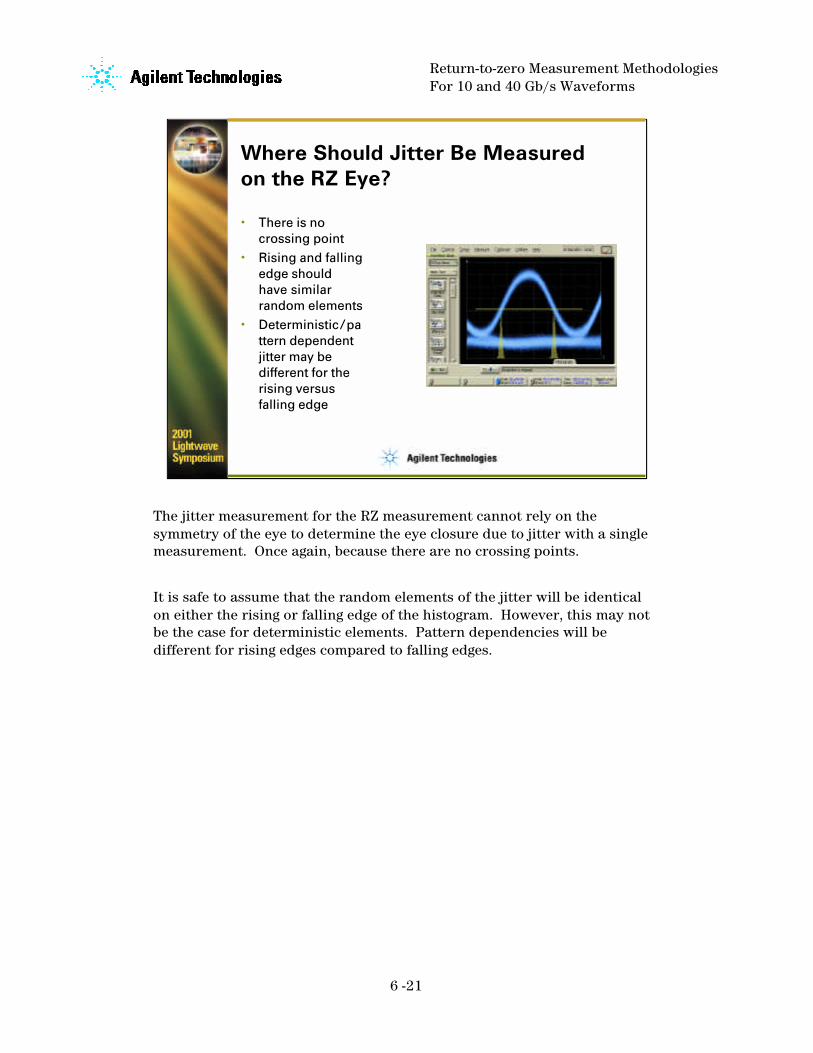
Where Should Jitter Be Measured on the RZ Eye?
• There is no crossing point
• Rising and falling edge should have similar random elements
• Deterministic/pattern dependent jitter may be different for the rising versus falling edge
The jitter measurement for the RZ measurement cannot rely on thesymmetry of the eye to determine the eye closure due to jitter with a single measurement. Once again, because there are no crossing points.
It is safe to assume that the random elements of the jitter will be identical on either the rising or falling edge of the histogram. However, this may not be the case for deterministic elements. Pattern dependencies will be different for rising edges compared to falling edges.
Return-to-zero Measurement MethodologiesFor 10 and 40 Gb/s Waveforms
6 -22
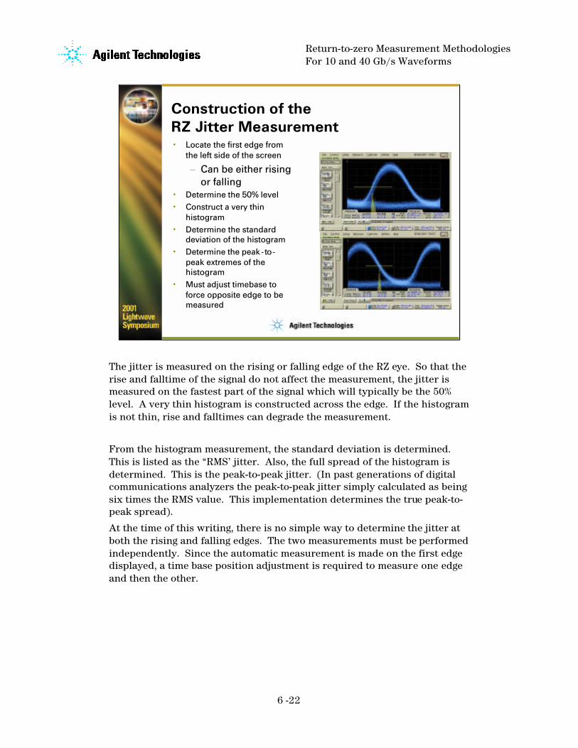
Construction of the RZ Jitter Measurement• Locate the first edge from
the left side of the screen
– Can be either rising or falling
• Determine the 50% level• Construct a very thin
histogram• Determine the standard
deviation of the histogram• Determine the peak-to-
peak extremes of the histogram
• Must adjust timebase to force opposite edge to be measured
The jitter is measured on the rising or falling edge of the RZ eye. So that the rise and falltime of the signal do not affect the measurement, the jitter is measured on the fastest part of the signal which will typically be the 50% level. A very thin histogram is constructed across the edge. If the histogram is not thin, rise and falltimes can degrade the measurement.
From the histogram measurement, the standard deviation is determined. This is listed as the “RMS’ jitter. Also, the full spread of the histogram is determined. This is the peak-to-peak jitter. (In past generations of digital communications analyzers the peak-to-peak jitter simply calculated as being six times the RMS value. This implementation determines the true peak-to-peak spread).
At the time of this writing, there is no simple way to determine the jitter at both the rising and falling edges. The two measurements must be performed independently. Since the automatic measurement is made on the first edge displayed, a time base position adjustment is required to measure one edge and then the other.
Return-to-zero Measurement MethodologiesFor 10 and 40 Gb/s Waveforms
6 -23
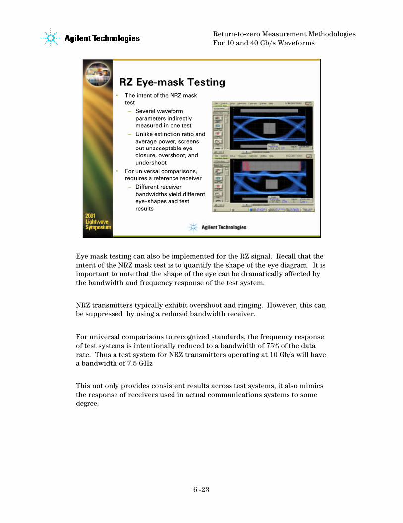
RZ Eye-mask Testing• The intent of the NRZ mask
test– Several waveform
parameters indirectly measured in one test
– Unlike extinction ratio and average power, screens out unacceptable eye closure, overshoot, and undershoot
• For universal comparisons, requires a reference receiver
– Different receiver bandwidths yield different eye-shapes and test results
Eye mask testing can also be implemented for the RZ signal. Recall that the intent of the NRZ mask test is to quantify the shape of the eye diagram. It is important to note that the shape of the eye can be dramatically affected by the bandwidth and frequency response of the test system.
NRZ transmitters typically exhibit overshoot and ringing. However, this can be suppressed by using a reduced bandwidth receiver.
For universal comparisons to recognized standards, the frequency response of test systems is intentionally reduced to a bandwidth of 75% of the data rate. Thus a test system for NRZ transmitters operating at 10 Gb/s will have a bandwidth of 7.5 GHz
This not only provides consistent results across test systems, it also mimics the response of receivers used in actual communications systems to some degree.

Return-to-zero Measurement MethodologiesFor 10 and 40 Gb/s Waveforms
6 -24
There Is No Standard Yet For an RZ Mask
• Reference receiver and mask should be designed concurrently
• What are the pulse shape parameters that are critical to screen?
• Potential mask concepts:
– Communications pulse templates
– Double trapezoid– Hybrids– Others
Although there may be a standard mask for RZ signals, to date there has been little work to design one. Several issues need to be determined. What is the ideal shape of the RZ signal. This may vary depending upon the system where it will be used. The receiver used in an actual communications system will quite possibly require more bandwidth than the receiver for an NRZ system at the same data rate. Thus the bandwidth of 75% of the data rate would become invalid.
The shape of the mask will likely be different than the standard central polygon and upper/lower boundaries used for NRZ. Some possible candidates are to have some form of pulse template similar to electrical communications masks, a pair of trapezoids to define the inner shape of the eye and the region between the two pulses.
Return-to-zero Measurement MethodologiesFor 10 and 40 Gb/s Waveforms
6 -25
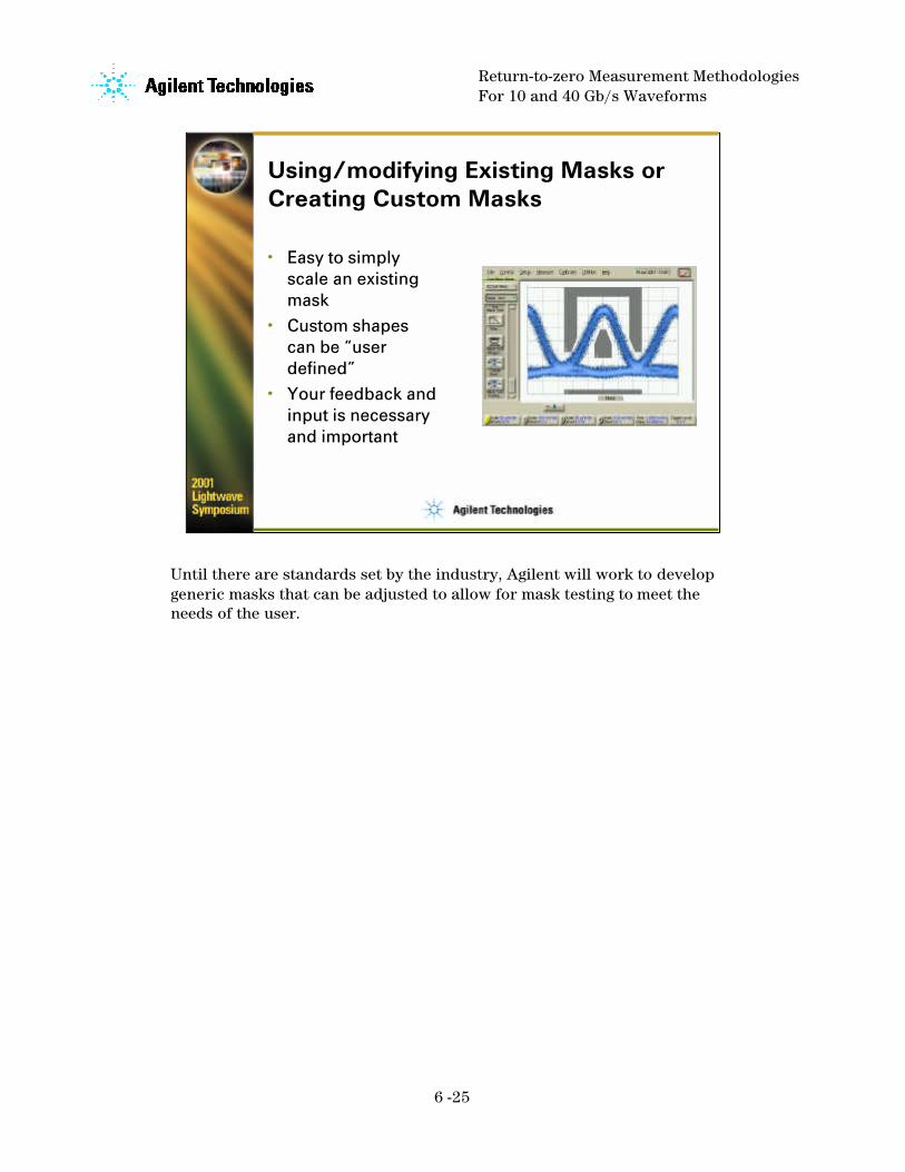
Using/modifying Existing Masks or Creating Custom Masks
• Easy to simply scale an existing mask
• Custom shapes can be “user defined”
• Your feedback and input is necessary and important
Until there are standards set by the industry, Agilent will work to develop generic masks that can be adjusted to allow for mask testing to meet the needs of the user.

Return-to-zero Measurement MethodologiesFor 10 and 40 Gb/s Waveforms
6 -26
Hardware Improvements for 40Gb/s and RZ Waveform Analysis
• Wider optical channel bandwidth • Reduced timebase jitter• Higher timebase resolution
In addition to the ability to make waveform measurements specific to RZ signals, there have been additional improvements to the digital communications analyzer for 40 Gb/s test. These include a widerbandwidth integrated channel for the instrument, reduced intrinsic jitter, and a higher resolution timesbase

Return-to-zero Measurement MethodologiesFor 10 and 40 Gb/s Waveforms
6 -27
Wider Optical Bandwidth Receiver
• Previous performance of integrated optical receiver was 30 GHz
• New receiver has much wider frequency response
– Faster impulse response
– Reduced distortion
86109A 30 GHzreceiver
‘New’86109B
The Agilent 86109B integrated optical receiver has an optical channel with over 40 GHz of bandwidth and an electrical channel with 50 GHz of bandwidth. (The previous generation of receivers had a bandwidth of 30 GHz using the 86109A, while the 86106A had 20+ GHz bandwidth but with significant pulse distortion).
With the increase in bandwidth, there can be tradeoff with pulse distortion. Note the ringing in the impulse response. Not only has the pulse width been significantly reduced (approximately 12 ps with a 5 ps impulse input), but the magnitude of the pulse aberrations has also been dramatically improved.

Return-to-zero Measurement MethodologiesFor 10 and 40 Gb/s Waveforms
6 -28
Reduced Timebase Jitter
• Specification of 2.5 ps RMS
• Typical performance of 86100A was 1.5 ps RMS
• Typical performance now is less than 1 ps– Consider that if
peak-to-peak jitter is approximately 6 times RMS, eye closure improved from 9 ps to 5 ps
– 40 Gb/s bit period only 25 ps
The jitter of the 86100 is specified at 2.5 ps rms. This would yield a peak-to-peak value of approximately 15 ps. Considering that the full bit period of a 40 Gb/s signal is only 25 ps, eye closure due to instrument jitter would be significant.
The 86100 oscilloscope mainframe jitter has been significantly improved such that the typical performance is less than 1 ps rms. Thus the eye closure due to instrument jitter is typically less than 5 ps. This is essential for an accurate view of the 40 Gb/s waveform.

Return-to-zero Measurement MethodologiesFor 10 and 40 Gb/s Waveforms
6 -29
Higher Resolution Timebase
• Original 86100 specification was 10 ps/division or 100 ps full screen
• New specification allows as low as 2 ps/division– At 10 ps/division a
40 Gb/s signal will have 4 bit periods or eyes displayed
– At 2 ps/division, can resolve to less than a bit period at 40 Gb/s
The last recent improvement is in timebase resolution. The original 86100 mainframe minimum timebase setting was 10 ps/division. Thus the full screen would cover 100 ps. For a 40 Gb/s signal, four full eye diagrams will be displayed. Since two adjacent eye diagrams contain virtually the same information, 75% of the display provides no useful information.
The 86100 mainframe can now have a display resolution as high as 2 ps/division. This allows a display span less than the bit period of the 40 Gb/s signal.

Return-to-zero Measurement MethodologiesFor 10 and 40 Gb/s Waveforms
6 -30
Conclusions
• RZ measurements will grow in importance as 40 Gb/s systems are developed and deployed– The initial measurement set will expand based
upon customer input. Your feedback is essential• RZ measurement capability and higher timebase
resolution for the Agilent 86100 mainframe are available through free firmware upgrades– Improved jitter performance is standard on all
86100 mainframes being shipped• Agilent will continue to work to improve
oscilloscope performance including bandwidth, jitter and other parameters critical to high-speed communications development.
The RZ measurement set is the initial offering from Agilent Technologies. As the industry gains experience with RZ signals and this measurement set, modifications as well as new measurements will be put in place. Your input is essential to achieve this.
The RZ measurement set as well as the improved timebase resolution are available through a free firmware upgrade to the 86100 digital communications analyzer mainframe. The sub-picosecond jitter capability is a standard feature of all 86100 mainframes shipped as of January 2001.
The author would like to recognize Chris MacGregor of Qtera for his assistance in defining and verifying the RZ measurement set.