Embed Size (px)
Citation preview
COMPATIBILITY (ISO 2943)
Full with fl uids: HH-HL-HM-HV-HTG(according to ISO 6743/4)For fl uids different than the above mentio-ned, please contact our Sales Department.
WORKING TEMPERATURE
From -25° to +110° C
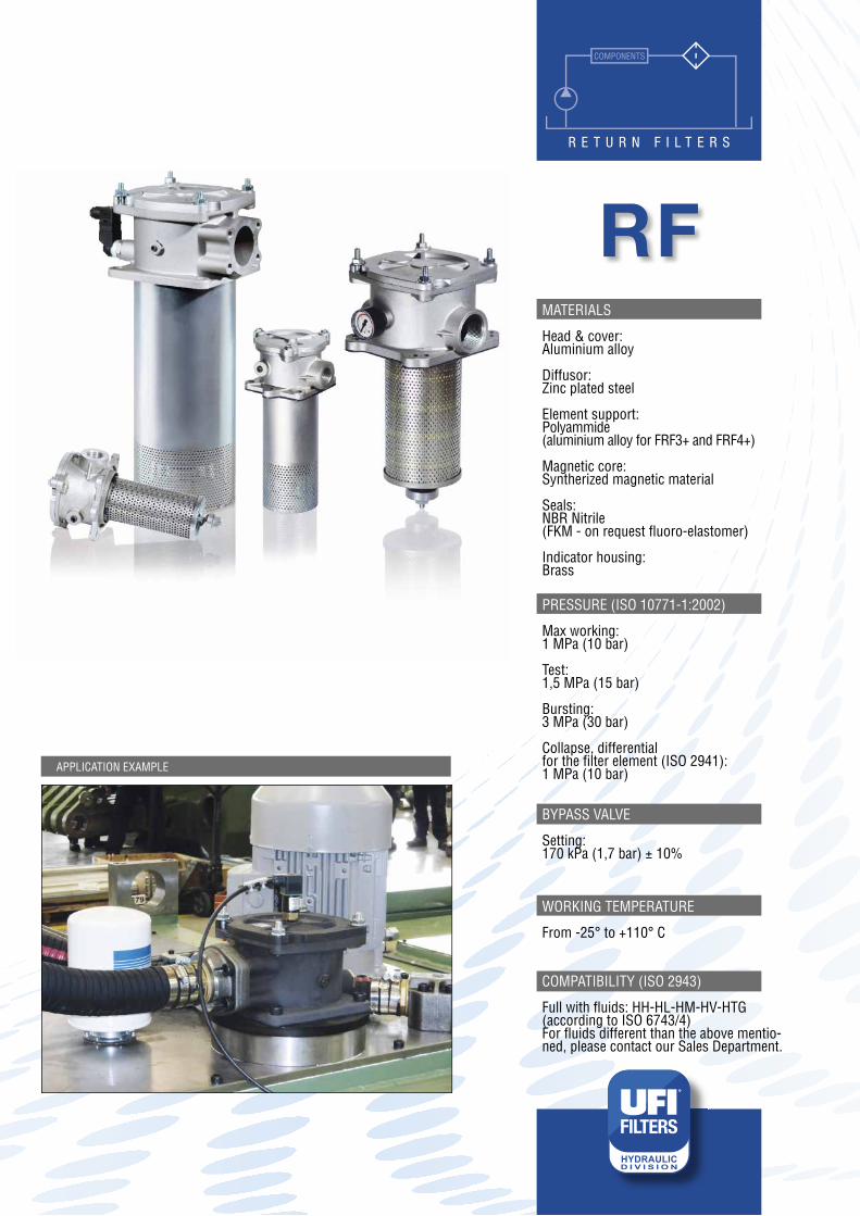
MATERIALS
Head & cover:Aluminium alloy
Diffusor:Zinc plated steel
Element support:Polyammide (aluminium alloy for FRF3+ and FRF4+)
Magnetic core:Syntherized magnetic material
Seals:NBR Nitrile (FKM - on request fl uoro-elastomer)
Indicator housing:Brass
PRESSURE (ISO 10771-1:2002)
Max working: 1 MPa (10 bar)
Test: 1,5 MPa (15 bar)
Bursting: 3 MPa (30 bar)
Collapse, differential for the fi lter element (ISO 2941): 1 MPa (10 bar)
BYPASS VALVE
Setting: 170 kPa (1,7 bar) ± 10%
RF
APPLICATION EXAMPLE
COMPONENTS
R E T U R N F I L T E R S

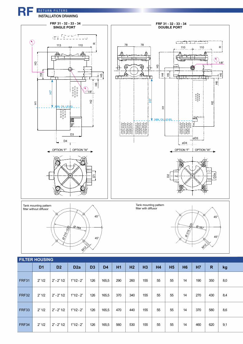
INSTALLATION DRAWINGR E T U R N F I LT E R SRF
SINGLE PORT FRF 11 - 12 - 13 - 14 FRF 11 - 12 - 13 - 14
22,5 68
R
H3
H4
H5
H6
H2
D3D4
H1
110
116
110ø 9,5
D1
FILTER HOUSING
kg
FRF11
FRF12
FRF13
FRF14
3/4” - 1” - 1” 1/4
3/4” - 1” - 1” 1/4
3/4” - 1” - 1” 1/4
3/4” - 1” - 1” 1/4
72
72
72
72
89
89
89
89
198
198
250
350
140
185
235
335
90
90
90
90
28÷32
28÷32
28÷32
28÷32
6
6
6
6
118
118
170
270
230
275
325
445
1,2
1,4
1,5
1,7
D1 D3 D4 H1 H2 H3 H5 H6 H7 R
38
38
38
38
H4
DOUBLE PORT
68
55
22,5 68R80
28
6H2
ø72
110D2
100
D1
ø9
ø126
”
H3
78 78
H4
H5 H5
H6
R
1/8”
H2
H1
øD3øD4
H1
68
55
22,5 68R80
38 28
6
1/8”ø8 6
H2
H3
ø7 2ø8 9
110D2
100
D2
H1
38
ø89
68
55
22,5 68R80
28
6H2
ø72
110D2
100
D1
ø9
ø126
”
H3
78 78
H4
H5 H5
H6
R
1/8”
H2
H1
øD3øD4
H1
68
55
22,5 68R80
38 28
6
1/8”ø8 6
H2
H3
ø7 2ø8 9
110D2
100
D2
H1
38
ø89
D2
1”
1”
1”
1”
Ø 90
Tank mounting patternfilter without diffusor
Tank mounting patternfilter with diffusor
Ø 88
Ø 1
26
M8
45°
45° Ø 1
26
M8
45°
45°
MIN. OIL LEVEL
H7
1/8”1/8”
MIN. OIL LEVEL
H7
22,5 68
R
H3
H4
H5
H6
H2
D3D4
H1
110
116
110ø 9,5
D1
OPTION “F” OPTION ”W” OPTION “F” OPTION ”W”
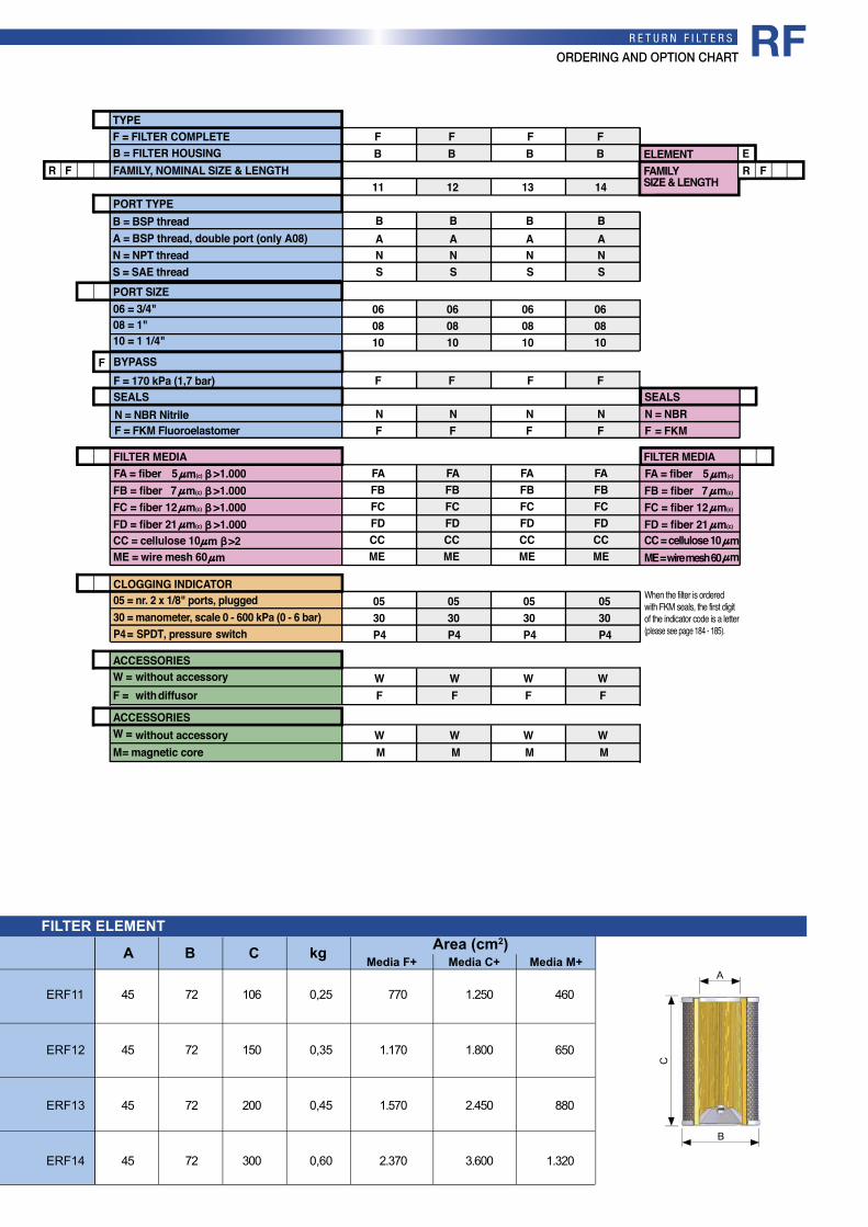
ORDERING AND OPTION CHARTR E T U R N F I LT E R S RF
N = NBRF = FKM
F
F
R14131211
B
NS
B
NS
B
NS
B
NA A A A
S
060810
060810
060810
060810
FFFF
NNNNFFFF
BYPASS
SEALS SEALSF = 170 kPa (1,7 bar)
PORT SIZE
PORT TYPE
FAMILY, NOMINAL SIZE & LENGTH
08 = 1"10 = 1 1/4"
06 = 3/4"
ER F
ELEMENTFAMILYSIZE & LENGTH
B = BSP thread
N = NPT threadS = SAE thread
A = BSP thread, double port (only A08)
N = NBR NitrileF = FKM Fluoroelastomer
B = FILTER HOUSINGF = FILTER COMPLETETYPE
WF
WF
WF
WF
ACCESSORIESW = without accessory F = with diffusor
WM
WM
WM
WM
ACCESSORIESW = M = magnetic core
FB
FB
FB
FB
FAFBFCFDCCME
FAFBFCFDCCME
FAFBFCFDCCME
FAFBFCFDCCME
FILTER MEDIA FILTER MEDIA
CC = cellulose 10ME = wire mesh 60
CC = cellulose 10ME = wire mesh 60
m >2m
>1.000FA = fiber 5 m(c)
>1.000FB = fiber 7 m(c)
>1.000FC = fiber 12 m(c)
>1.000FD = fiber 21 m(c)
mm
FA = fiber 5 m(c)
FB = fiber 7 m(c)
FC = fiber 12 m(c)
FD = fiber 21 m(c)
0530P4
0530P4
0530P4
0530P4
CLOGGING INDICATOR05 = nr. 2 x 1/8" ports, plugged30 = manometer, scale 0 - 600 kPa (0 - 6 bar)P4 = pressureSPDT, switch
When the filter is ordered with FKM seals, the first digit of the indicator code is a letter (please see page 184 - 185).
without accessory
1.250
1.800
2.450
3.600
770
1.170
1.570
2.370
106
150
200
300
72
72
72
72
45
45
45
45
460
650
880
1.320
FILTER ELEMENT
C
A
B
0,25
0,35
0,45
0,60
ERF11
ERF12
ERF13
ERF14
Area (cm2)Media F+ Media C+ Media M+A B C kg

134
INSTALLATION DRAWINGR E T U R N F I LT E R S
68
55
22,5 68R80
28
6H2
ø72
110D2
100
D1
ø9
ø126
”
H3
78 78
H4
H5 H5
H6
R
1/8”
H2
H1
øD3øD4
H1
68
55
22,5 68R80
38 28
61/8”
ø8 6
H2
H3
ø7 2ø8 9
110D2
100
D2
H1
38
ø89
FRF 22 - 23 - 24SINGLE PORT DOUBLE PORT
FILTER HOUSING
kg
FRF22
FRF23
FRF24
1” 1/2
1” 1/2
1” 1/2
133
133
133
106
106
106
250
320
525
225
295
500
129
129
129
50
50
50
36
36
36
12
12
12
150
220
425
310
380
580
4,2
4,7
5,0
D1 D3 D4 H1 H2 H3 H5 H6 H7 RH4D2
1” 1/4 ÷ 1” 1/2
1” 1/4 ÷ 1” 1/2
1” 1/4 ÷ 1” 1/2
FRF 22 - 23 - 24
68
55
22,5 68R80
28
6H2
ø72
110D2
100
D1
ø9
ø126
”
H3
78 78
H4
H5 H5
H6
R
1/8”
H2
H1
øD3øD4
H1
68
55
22,5 68R80
38 28
61/8”
ø8 6
H2
H3
ø7 2ø8 9
110D2
100
D2
H1
38
ø89
MIN. OIL LEVEL
H7
Tank mounting patternfilter without diffusor
Tank mounting patternfilter with diffusor
Ø 131
Ø 1
75
M8
45°
45°
Ø 134
Ø 1
75
M8
45°
45°
22,5 68
R
H3
H4
H5
H6
H2
D3D4
H1
110
116
110ø 9,5
D1
22,5 68
R
H3
H4
H5
H6
H2
D3D4
H1
110
116
110ø 9,5
D1
MIN. OIL LEVEL
H7 1/8”
100
H3
H4
H1 H2
D4
D1
D3
H6
H5
9090 90
D1
D2
R
OPTION “F” OPTION ”W” OPTION “F” OPTION ”W”
RF

WF
WF
ACCESSORIESW = F = with diffusor
WM
WM
ACCESSORIESW = M = magnetic core
FAFBFCFDCCME
FAFBFCFDCCME
FILTER MEDIA FILTER MEDIA
CC = cellulose 10ME = wire mesh 60
CC = cellulose 10ME = wire mesh 60
m >2m
>1.000FA = fiber 5 m(c)
>1.000FB = fiber 7 m(c)
>1.000FC = fiber 12 m(c)
>1.000FD = fiber 21 m(c)
mm
FA = fiber 5 m(c)
FB = fiber 7 m(c)
FC = fiber 12 m(c)
FD = fiber 21 m(c)
PORT SIZE
N = NBR
FF
NN
F BYPASS
SEALS SEALSF = 170 kPa (1,7 bar)
N = NBR Nitrile
F
N
12D1
12D1
12 = 1" 1/2D1 = 1" 1/2 + fl. 1" 1/4 (only AD1)
12D1
WF
WM
22 23FR
B BA
BA
PORT TYPE
FAMILY, NOMINAL SIZE & LENGTHER F
ELEMENTFAMILYSIZE & LENGTH
B = FILTER HOUSINGF = FILTER COMPLETETYPE
FB
FB
24
ANN NSS SFF FPP P
FB
FAFBFCFDCCME
0530
035B6B7BT0
0530
035B6B7BT0
0530
035B6B7BT0
CLOGGING INDICATOR05 = nr. 2 x 1/8" ports, plugged30 = manometer, scale 0 - 600 kPa (0 - 6 bar)
03 = port for differential indicator, plugged5B = visual differential 130 kPa (1,3 bar)6B = electrical differential 130 kPa (1,3 bar)7B = indicator 6B with LED T0 = elect. diff. 130 kPa (1,3 bar) with thermostat 30°C
B = BSP thread
N = NPT threadS = SAE threadF = SAE flange 3000 psi
A = BSP thread, double port (only AD1)
P = SAE thread 3000 psi + BSP, double port
When the filter is ordered with FKM seals, the first digit of the indicator code is a letter (please see page 184 - 185).
F = FKMFFFF = FKM Fluoroelastomer
P4 P4 P4P4 = pressureSPDT, switch
without accessory
without accessory
ORDERING AND OPTION CHARTR E T U R N F I LT E R S
C
A
B
N.B. Indicatorseries 70 only on request
FILTER ELEMENT
4.600
6.400
11.800
3.900
5.400
9.700
190
260
465
106
106
106
72
72
72
1.500
2.050
3.670
0,75
1,00
1,50
ERF22
ERF23
ERF24
Area (cm2)Media F+ Media C+ Media M+A B C kg
RF
INSTALLATION DRAWINGR E T U R N F I LT E R S
FRF31
FRF32
FRF33
FRF34
kg
2” 1/2
2” 1/2
2” 1/2
2” 1/2
2” - 2” 1/2
2” - 2” 1/2
2” - 2” 1/2
2” - 2” 1/2
126
126
126
126
1”1/2 - 2”
1”1/2 - 2”
1”1/2 - 2”
1”1/2 - 2”
165,5
165,5
165,5
165,5
290
370
470
560
260
340
440
530
155
155
155
155
55
55
55
55
55
55
55
55
14
14
14
14
190
270
370
460
350
430
580
620
8,0
8,4
8,6
9,1
D1 D3D2a D4 H1 H2 H3 H5 H6 H7 RD2 H4
FILTER HOUSING
FRF 31 - 32 - 33 - 34DOUBLE PORTSINGLE PORT
FRF 31 - 32 - 33 - 34
Ø 164 Ø 167
Tank mounting patternfilter with diffusor
Ø 2
15 ÷
220
Ø 2
15 ÷
220
M12
45°
45°
Tank mounting patternfilter without diffusor
M12
45°
45°
22,5 68
R
H3
H4
H5
H6
H2
D3D4
H1
110
116
110ø 9,5
D1
22,5 68
R
H3
H4
H5
H6
H2
D3D4
H1
110
116
110ø 9,5
D1
MIN. OIL LEVEL
H7 1/8”
113
H3
H4
H1 H2
D4
D1
D3
H6
H5
110 R
68
55
22,5 68R80
28
6H2
ø72
110D2
100
D1
ø9
ø126
”
H3
78 78
H4
H5 H5
H6
R
1/8”
H2
H1
øD3øD4
H1
68
55
22,5 68R80
38 28
61/8”
ø8 6
H2
H3
ø7 2ø8 9
110D2
100
D2
H1
38
ø89
68
55
22,5 68R80
28
6H2
ø72
110D2
100
D1
ø9
ø126
”
H3
78 78
H4
H5 H5
H6
R
1/8”
H2
H1
øD3øD4
H1
68
55
22,5 68R80
38 28
61/8”
ø8 6
H2
H3
ø7 2ø8 9
110D2
100
D2
H1
38
ø89
MIN. OIL LEVEL
H7
110
D2
D2a
110
OPTION “F” OPTION ”W” OPTION “F” OPTION ”W”
RF

ORDERING AND OPTION CHARTR E T U R N F I LT E R S
C
A
B
N.B. Indicatorseries 70 only on request
Area (cm2)Media F+ Media C+ Media M+A B C kg
ERF31
ERF32
ERF33
ERF34
6.650
9.200
12.400
15.400
5.500
7.700
10.400
12.800
210
290
390
480
126
126
126
126
92
92
92
92
2.250
3.150
4.250
5.250
1,15
1,50
1,90
2,20
FILTER ELEMENT
N = NBR
F
F
R34333231
F F F FP P P P
20DAD7
DAD7
DAD7
DAD7
20 20 20
FFFF
NNNN
BYPASS
SEALS SEALSF = 170 kPa (1,7 bar)
PORT SIZE
PORT TYPE
FAMILY, NOMINAL SIZE & LENGTH
20 = 2"1/2DA = 2"1/2 + 2"D7 = 2"+ 1"1/2
ER F
ELEMENTFAMILYSIZE & LENGTH
N = NBR Nitrile
B = FILTER HOUSINGF = FILTER COMPLETETYPE
WF
WF
WF
WF
ACCESSORIESW = F = with diffusor
WM
WM
WM
WM
ACCESSORIESW = M = magnetic core
FB
FB
FB
FB
FAFBFCFDCCME
FAFBFCFDCCME
FAFBFCFDCCME
FAFBFCFDCCME
FILTER MEDIA FILTER MEDIA
CC = cellulose 10ME = wire mesh 60
CC = cellulose 10ME = wire mesh 60
m >2m
>1.000FA = fiber 5 m(c)
>1.000FB = fiber 7 m(c)
>1.000FC = fiber 12 m(c)
>1.000FD = fiber 21 m(c)
mm
FA = fiber 5 m(c)
FB = fiber 7 m(c)
FC = fiber 12 m(c)
FD = fiber 21 m(c)
0530P4035B6B7BT0
035B6B7BT0
035B6B7BT0
035B6B7BT0
0530P4
0530P4
0530P4
F = SAE flange 3000 psiP = SAE thread 3000 psi + BSP, double port
F = FKMFFF FF = FKM Fluoroelastomer
When the filter is ordered with FKM seals, the first digit of the indicator code is a letter (please see page 184 - 185).
CLOGGING INDICATOR05 = nr. 2 x 1/8" ports, plugged30 = manometer, scale 0 - 600 kPa (0 - 6 bar)
03 = port for differential indicator, plugged5B = visual differential 130 kPa (1,3 bar)6B = electrical differential 130 kPa (1,3 bar)7B = indicator 6B with LED T0 = elect. diff. 130 kPa (1,3 bar) with thermostat 30°C
P4 = pressureSPDT, switch
without accessory
without accessory
RF

FRF 41 - 42 - 43 - 44DOUBLE PORT
INSTALLATION DRAWINGR E T U R N F I LT E R S
FRF41
FRF42
FRF43
FRF44
3”
3”
3”
3”
4”
4”
4”
4”
405
620
900
1.165
396
611
891
1.156
205
420
700
965
600
810
1.090
1.360
D1 H1 H2 H3 RD2
FILTER HOUSING
H1
D1
M1267,5°
ø295
ø250
22,5°D
2
175
175157157
ø 245
ø 203
170
76
31
H2
R
MIN. OIL LEVEL
H3
Tank mounting pattern
1/8”
OPTION “F” OPTION ”W”
RF

CLOGGING INDICATOR05 = nr. 2 x 1/8" ports, plugged30 = manometer, scale 0 - 600 kPa (0 - 6 bar)
03 = port for differential indicator, plugged5B = visual differential 130 kPa (1,3 bar)6B = electrical differential 130 kPa (1,3 bar)7B = indicator 6B with LED T0 = elect. diff. 130 kPa (1,3 bar) with thermostat 30°C
P4 = pressureSPDT, switch
N = NBR
F
F
R44434241
F F F FP P P P
24 24 24 2432D9 D9 D9 D9
32 32 32
FFFF
NNNN
BYPASS
SEALS SEALSF = 170 kPa (1,7 bar)
PORT SIZE
PORT TYPE
FAMILY, NOMINAL SIZE & LENGTH
24 = 3" 32 = 4" D9= 3"+ 4"
ER F
ELEMENTFAMILYSIZE & LENGTH
N = NBR Nitrile
B = FILTER HOUSINGF = FILTER COMPLETETYPE
WF
WF
WF
WF
ACCESSORIESW = F = with diffusor
WM
WM
WM
WM
ACCESSORIESW = M = magnetic core
FB
FB
FB
FB
FAFBFCFDCCME
FAFBFCFDCCME
FAFBFCFDCCME
FAFBFCFDCCME
FILTER MEDIA FILTER MEDIA
CC = cellulose 10ME = wire mesh 60
CC = cellulose 10ME = wire mesh 60
m >2m
>1.000FA = fiber 5 m(c)
>1.000FB = fiber 7 m(c)
>1.000FC = fiber 12 m(c)
>1.000FD = fiber 21 m(c)
mm
FA = fiber 5 m(c)
FB = fiber 7 m(c)
FC = fiber 12 m(c)
FD = fiber 21 m(c)
0530P4035B6B7BT0
035B6B7BT0
035B6B7BT0
035B6B7BT0
0530P4
0530P4
0530P4
F = SAE flange 3000 psiP = SAE thread 3000 psi, double port
F = FKMF F F FF = FKM Fluoroelastomer
When the filter is ordered with FKM seals, the first digit of the indicator code is a letter (please see page_______).
without accessory
without accessory
D9 only
ORDERING AND OPTION CHARTR E T U R N F I LT E R S
C
A
B
Area (cm2)Media F+ Media C+ Media M+A B C kg
ERF41
ERF42
ERF43
ERF44
22.100
37.000
55.500
74.000
17.900
30.000
45.200
60.000
330
545
825
1.090
203
203
203
203
157
157
157
157
6.400
10.800
16.200
21.800
3,90
5,20
9,00
13,00
FILTER ELEMENT
N.B. Indicatorseries 70 only on request
RF
R E T U R N F I LT E R S
CLEAN FILTER ELEMENT PRESSURE DROP WITH F+, C+ AND ME MEDIA
(depending both on the internal diameter of the element and on the fi lter media)
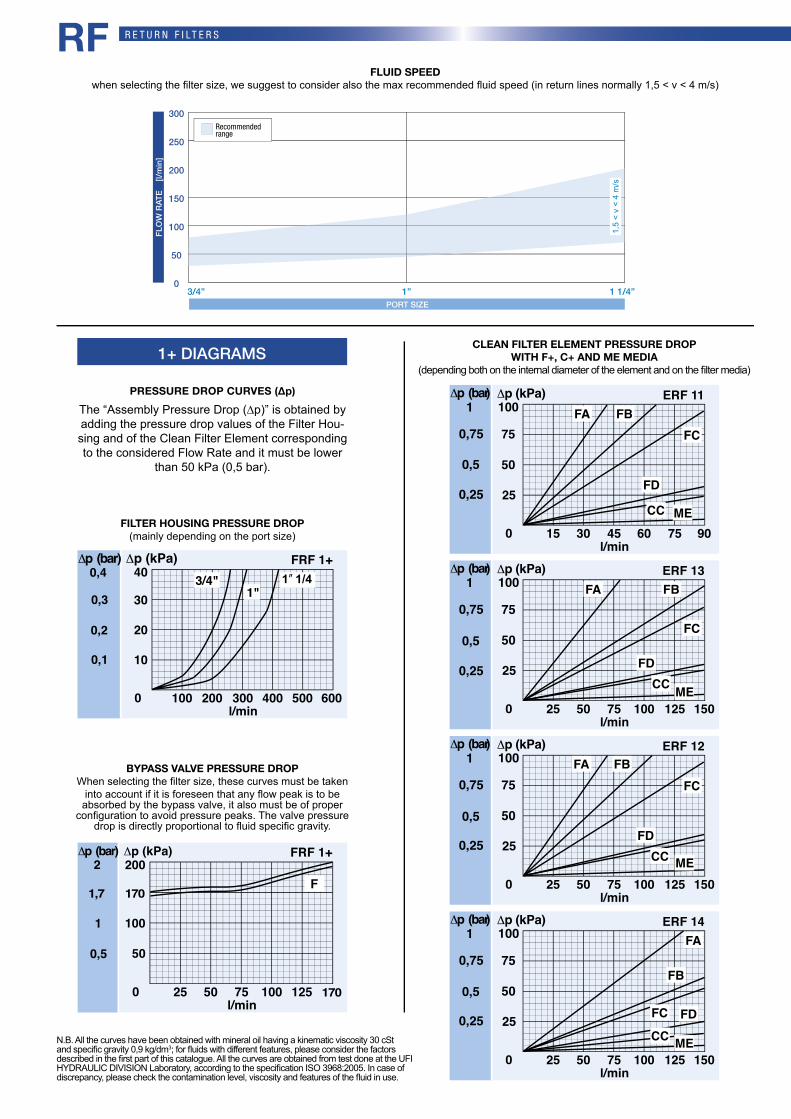
The “Assembly Pressure Drop (∆p)” is obtained by adding the pressure drop values of the Filter Hou-sing and of the Clean Filter Element corresponding to the considered Flow Rate and it must be lower
than 50 kPa (0,5 bar).
PRESSURE DROP CURVES (∆p)
N.B. All the curves have been obtained with mineral oil having a kinematic viscosity 30 cSt and specifi c gravity 0,9 kg/dm3; for fl uids with different features, please consider the factors described in the fi rst part of this catalogue. All the curves are obtained from test done at the UFI HYDRAULIC DIVISION Laboratory, according to the specifi cation ISO 3968:2005. In case of discrepancy, please check the contamination level, viscosity and features of the fl uid in use.
l/min
FRF 1+
0 600
40Δp (kPa)
100 200 300 400 500
10
20
303/4"
1"
Δ
0,1
0,2
0,3
0,4p (bar)
Δp (bar)
0,25
0,5
0,75
1
l/min
ERF 11
0 90
25
50
75
100
15 30 45 60 75
FCFB
CC
FD
Δp (kPa)FA
ME
Δp (bar)
0,25
0,5
0,75
1
l/min
ERF 12
0 150
25
50
75
100
25 50 75 100 125
FCFB
CCFD
Δp (kPa)FA
ME
Δp (bar)
0,25
0,5
0,75
1
l/min
ERF 13
0 150
25
50
75
100
25 50 75 100 125
FC
FB
CCFD
Δp (kPa)FA
ME
Δp (bar)
0,25
0,5
0,75
1
l/min
ERF 14
0 150
25
50
75
100
25 50 75 100 125
FC
FB
CCFD
Δp (kPa)FA
ME
BYPASS VALVE PRESSURE DROPWhen selecting the fi lter size, these curves must be taken
into account if it is foreseen that any fl ow peak is to be absorbed by the bypass valve, it also must be of proper
confi guration to avoid pressure peaks. The valve pressure drop is directly proportional to fl uid specifi c gravity.
FILTER HOUSING PRESSURE DROP(mainly depending on the port size)
1+ DIAGRAMS
FLUID SPEEDwhen selecting the fi lter size, we suggest to consider also the max recommended fl uid speed (in return lines normally 1,5 < v < 4 m/s)
300
250
200
150
100
50
03/4” 1” 1 1/4”
FLO
W R
ATE
[l/
min
]
PORT SIZE
Recommended range
1,5
< v
< 4
m/s
1” 1/4
l/min
FRF 1+
0
200Δp (kPa)
25 50 75 100 125
50
100
Δp (bar
0,5
1
2)
F
RF
1,7
170
170
R E T U R N F I LT E R S
CLEAN FILTER ELEMENT PRESSURE DROP WITH F+, C+ AND ME MEDIA
(depending both on the internal diameter of the element and on the fi lter media)
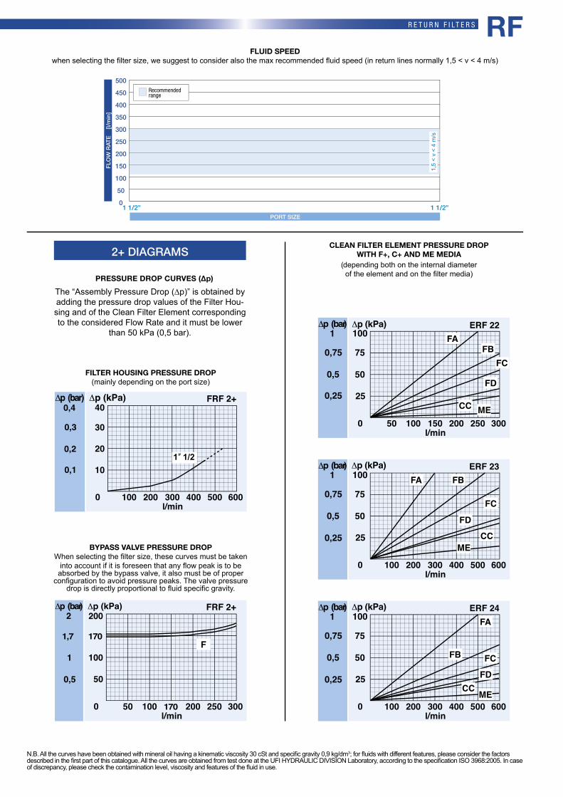
The “Assembly Pressure Drop (∆p)” is obtained by adding the pressure drop values of the Filter Hou-sing and of the Clean Filter Element corresponding to the considered Flow Rate and it must be lower
than 50 kPa (0,5 bar).
PRESSURE DROP CURVES (∆p)
N.B. All the curves have been obtained with mineral oil having a kinematic viscosity 30 cSt and specifi c gravity 0,9 kg/dm3; for fl uids with different features, please consider the factors described in the fi rst part of this catalogue. All the curves are obtained from test done at the UFI HYDRAULIC DIVISION Laboratory, according to the specifi cation ISO 3968:2005. In case of discrepancy, please check the contamination level, viscosity and features of the fl uid in use.
BYPASS VALVE PRESSURE DROPWhen selecting the fi lter size, these curves must be taken
into account if it is foreseen that any fl ow peak is to be absorbed by the bypass valve, it also must be of proper
confi guration to avoid pressure peaks. The valve pressure drop is directly proportional to fl uid specifi c gravity.
FILTER HOUSING PRESSURE DROP(mainly depending on the port size)
l/min
FRF 2+
0 600
40Δp (kPa)
100 200 300 400 500
10
20
30
Δ
0,1
0,2
0,3
0,4p (bar)
Δp (bar)
0,25
0,5
0,75
1
l/min
ERF 22
0 300
25
50
75
100
50 100 150 200 250
FC
FD
FB
CC
Δp (kPa)FA
ME
Δp (bar)
0,25
0,5
0,75
1
l/min
ERF 23
0 600
25
50
75
100
100 200 300 400 500
FC
FD
FB
CC
Δp (kPa)FA
ME
Δp (bar)
0,25
0,5
0,75
1
l/min
ERF 24
0 600
25
50
75
100
100 200 300 400 500
FC
CCFD
Δp (kPa)
FB
FA
ME
l/min
FRF 2+
0 300
200Δp (kPa)
50 100 200 250
F
50
100
Δp (bar)
0,5
1
2
2+ DIAGRAMS
FLUID SPEEDwhen selecting the fi lter size, we suggest to consider also the max recommended fl uid speed (in return lines normally 1,5 < v < 4 m/s)
500
450
400
350
300
250
200
150
100
50
01 1/2” 1 1/2”
FLO
W R
ATE
[l/
min
]
PORT SIZE
Recommended range
1,5
< v
< 4
m/s
1” 1/2
RF
1,7
170
170

R E T U R N F I LT E R S
l/min
FRF 3+
0 1200
40Δp (kPa)
200 400 600 800 1000
10
20
30
Δp (bar)
0,1
0,2
0,3
0,4
Δp (bar)
0,25
0,5
0,75
1
l/min
ERF 31
0 600
25
50
75
100
100 200 300 400 500
FCFB
CC
FD
Δp (kPa)FA
ME
Δp (bar)
0,25
0,5
0,75
1
l/min
ERF 32
0 600
25
50
75
100
100 200 300 400 500
FC
FB
CCFD
Δp (kPa)FA
ME
Δp (bar)
0,25
0,5
0,75
1
l/min
ERF 33
0 1200
25
50
75
100
200 400 600 800 1000
FCFB
CC
FD
Δp (kPa)FA
ME
Δp (bar)
0,25
0,5
0,75
1
l/min
ERF 34
0 1200
25
50
75
100
200 400 600 800 1000
FC
FB
CCFD
Δp (kPa)FA
ME
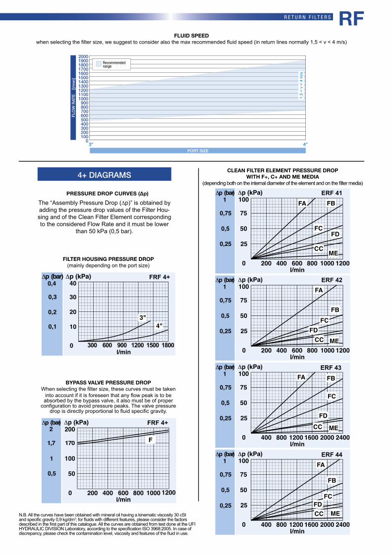
CLEAN FILTER ELEMENT PRESSURE DROP WITH F+, C+ AND ME MEDIA
(depending both on the internal diameter of the element and on the fi lter media)
N.B. All the curves have been obtained with mineral oil having a kinematic viscosity 30 cSt and specifi c gravity 0,9 kg/dm3; for fl uids with different features, please consider the factors described in the fi rst part of this catalogue. All the curves are obtained from test done at the UFI HYDRAULIC DIVISION Laboratory, according to the specifi cation ISO 3968:2005. In case of discrepancy, please check the contamination level, viscosity and features of the fl uid in use.
BYPASS VALVE PRESSURE DROPWhen selecting the fi lter size, these curves must be taken
into account if it is foreseen that any fl ow peak is to be absorbed by the bypass valve, it also must be of proper
confi guration to avoid pressure peaks. The valve pressure drop is directly proportional to fl uid specifi c gravity.
FILTER HOUSING PRESSURE DROP(mainly depending on the port size)
The “Assembly Pressure Drop (∆p)” is obtained by adding the pressure drop values of the Filter Hou-sing and of the Clean Filter Element corresponding to the considered Flow Rate and it must be lower
than 50 kPa (0,5 bar).
PRESSURE DROP CURVES (∆p)
3+ DIAGRAMS
FLUID SPEEDwhen selecting the fi lter size, we suggest to consider also the max recommended fl uid speed (in return lines normally 1,5 < v < 4 m/s)
1000
900
800
700
600
500
400
300
200
100
02 1/2” 2 1/2”
FLO
W R
ATE
[l/
min
]
PORT SIZE
Recommended range
1,5
< v
< 4
m/s
2” 1/2
RF
l/min
FRF 3+
0 600
200Δp (kPa)
100 200 300 400 500
50
100
Δp (bar)
0,5
1
2F
1,7 170
R E T U R N F I LT E R S
CLEAN FILTER ELEMENT PRESSURE DROP WITH F+, C+ AND ME MEDIA
(depending both on the internal diameter of the element and on the fi lter media)
N.B. All the curves have been obtained with mineral oil having a kinematic viscosity 30 cSt and specifi c gravity 0,9 kg/dm3; for fl uids with different features, please consider the factors described in the fi rst part of this catalogue. All the curves are obtained from test done at the UFI HYDRAULIC DIVISION Laboratory, according to the specifi cation ISO 3968:2005. In case of discrepancy, please check the contamination level, viscosity and features of the fl uid in use.
BYPASS VALVE PRESSURE DROPWhen selecting the fi lter size, these curves must be taken
into account if it is foreseen that any fl ow peak is to be absorbed by the bypass valve, it also must be of proper
confi guration to avoid pressure peaks. The valve pressure drop is directly proportional to fl uid specifi c gravity.
FILTER HOUSING PRESSURE DROP(mainly depending on the port size)
The “Assembly Pressure Drop (∆p)” is obtained by adding the pressure drop values of the Filter Hou-sing and of the Clean Filter Element corresponding to the considered Flow Rate and it must be lower
than 50 kPa (0,5 bar).
PRESSURE DROP CURVES (∆p)
4+ DIAGRAMS
FLUID SPEEDwhen selecting the fi lter size, we suggest to consider also the max recommended fl uid speed (in return lines normally 1,5 < v < 4 m/s)
l/min
ERF 41
0 1200
25
50
75
100
200 400 600 800 1000
FC
FB
CC
FD
Δp (kPa)FA
ME
Δp (bar)
0,25
0,5
0,75
1
l/min
ERF 42
0 1200
25
50
75
100
200 400 600 800 1000
FCFB
FD
Δp (kPa)FA
CC ME
Δp (bar)
0,25
0,5
0,75
1
l/min
ERF 43
0 2400
25
50
75
100
400 800 1200 1600 2000
FC
FB
FD
Δp (kPa)
CC ME
Δp (bar)
0,25
0,5
0,75
1 FA
l/min
ERF 44
0 2400
25
50
75
100
400 800 1200 1600 2000
FC
FB
FD
Δp (kPa)
CC ME
Δp (bar)
0,25
0,5
0,75
1 FA
ERF 41
ERF 43
ERF 42
ERF 44
l/min0
40Δp (kPa)
10
20
30
Δ
0,1
0,2
0,3
0,4FRF 4+
300 600 900 1200 1500 1800
3"4"
p (bar)
20001900180017001600150014001300120011001000900800700600500400300200100
03” 4”
FLO
W R
ATE
[l/
min
]
PORT SIZE
Recommended range
1,5
< v
< 4
m/s
l/min0 1200
200Δp (kPa)
200 400 600 800 1000
50
100
Δp (bar)
0,5
1
2FRF 4+
F
RF
1,7 170

R E T U R N F I LT E R S
For further technical informations and other options see page 184-185.
Tech
nica
l dat
a su
bjec
t to
varia
tions
with
out p
rior n
otic
e. R
F - E
N -
05/2
017
CLOGGING INDICATOR
CLOGGING INDICATORA visual or differential indicator (dif-ferential indicator with thermostat is an available option) allows moni-toring of the element condition and provides maximum element life by indicating the exact time for the ele-ment replacement. The port for the indicator is a standard feature.
DIFFUSORThe diffusor (available as an option) smooths the oil flow thus reducing turbolence inside the tank even in case of large flow rates.
BYPASSThe bypass function is obtained by the filter element moving axially, in such a way that the contaminant is retained in the filter element during bypass conditions.
INSIDE TO OUTSIDE FILTRATION“Inside-to-outside” filtration ensu-res the contaminant is retained insi-de the element during replacement; also filling or top-up of the reservoir can be done through the filter thus avoiding the ingression of new con-taminant.
MAGNETIC COREThe magnetic core (available as an option) ensures a magnetic pre-filtration of ferrous particles, even during bypass conditions.
SPARE PARTS ELEMENTS (For filling up see table “Ordering and option chart”)
5B
T0
6B - 7B
SERIES 30
FRB F E R F
FILTER ELEMENT CLOGGING INDICATOR ACCESSORY ACCESSORYFILTER HOUSING
MAGNETIC CORE DIFFUSOR
FRF11FRF12FRF13FRF14FRF22FRF23FRF24FRF31FRF32FRF33FRF34FRF41FRF42FRF43FRF44
521.0055.2521.0055.2521.0055.2521.0055.2521.0020.2521.0020.2521.0020.2521.0021.2521.0021.2521.0021.2521.0021.2521.0095.2521.0095.2521.0095.2521.0095.2
521.0056.2521.0056.2521.0056.2521.0056.2521.0057.2521.0057.2521.0057.2521.0058.2521.0058.2521.0058.2521.0058.2521.0096.2521.0096.2521.0096.2521.0096.2
NBR FKM
SPARE SPRING
FRF11FRF12FRF13FRF14FRF22FRF23FRF24FRF31FRF32FRF33FRF34FRF41FRF42FRF43FRF44
008.0282.1008.0282.1008.0282.1008.0282.1008.0269.1008.0269.1008.0269.1008.0275.1008.0275.1008.0275.1008.0275.1008.0283.1008.0283.1008.0283.1008.0283.1
SPARE SEAL KIT
Differential
SERIES P4
RF
Is this datasheet the latest release?
Please check on our website.


![2018 Shamrock [OscarSmith] - L3 & Xcel Printed: …Lvl3-Xcel...2010 Preslei Ruiz Capital 9.300 8.625 8.975 9.300 36.200 1T 4 3 1 1 1 2011 Adalynn Smith Capital 9.000 8.750 9.200 9.200](https://img.pdfslide.us/doc/110x75/5c458a0993f3c34c4b29c0e9/2018-shamrock-oscarsmith-l3-xcel-printed-lvl3-xcel-2010-preslei-ruiz-capital.jpg)