Embed Size (px)
Citation preview
J. Appl. Environ. Biol. Sci., 6(2S)222-239, 2016
© 2016, TextRoad Publication
ISSN: 2090-4274
Journal of Applied Environmental
and Biological Sciences
www.textroad.com
Corresponding Author: Somayeh Khatibi, Msc Student in Restoration and Rehabilitation of Historical Structures - Science and
Research Faculty of Tehran Central Branch- Islamic Azad University [email protected]
Retrofitting the Old Bridge of Dezful
Somayeh Khatibi1*, Mehrshad Mehrdadiaan2
1MscStudent in Restoration and Rehabilitation of Historical Structures - Science and Research Faculty of Tehran
Central Branch- Islamic Azad University 2Msc Student in Architecture- Science and Research Faculty of Khuzistan- Islamic Azad University
Received: January2, 2016 Accepted: February 29, 2016
ABSTRACT
The objective of the study is the proposing of a method for the retrofitting of the structure of the old bridge in the
city of Dezful using a descriptive analytical approach. In order to develop such an approach a vast library research
was conducted and various resources reviewed. The old bridge of Dezful is one of the few remaining ancient
structures in existence which was constructed in the late Sassanid era and which reflects the local and traditional
forms of the city. Using local materials, the ancient architects of the bridge have sought to create an aesthetic and
durable structure which has remained in place after more than 1,700 years. The focus of the study is however on the
retrofitting of this ancient structure in the city of Dezful and the sustaining of it for future generations of
architectural engineers.
KEY WORDS: Traditional architecture; retrofitting; the old bridge; the city of Dezful
_________________________________________________________________________________________
1. INTRODUCTION
Among one of the historical structures in Iran with a history spanning 1,700 years is the bridge at Dezful
which was constructed towards the end of the Sassanid period during the reign of Shappur I using dressed stone ,
mortar and is some places baked clay brick .The bridge consists of 14 original arches; 13 arcs and 3 contemporary
concrete arches. Some of the pedestals of the bridge are also related to more contemporary eras. The bridge consists
of 20 pedestals which operated as water ways. The maximum height of the structure is 10 meters; with a deck width
of six meters, and it is approximately 350 meters in length. The satellite images below show the position of the old
bridge of Dezful across the Dezriver.
Fig.1 Satellite image of the old bridge of Dezful
(source Google)
Fig. 2 Cadaster image of the old bridge of Dezfulcira
1956 (National Heritage archives)
222
Khatibi and Mehrdadiaan, 2016
Historians and Researchers have unanimously agreed that the construction of the bridge is related to the
Sassanid period and most attribute the building of this weir-bridge as concurrent with the founding of the city of
Dezful. The bridge has been repetitively damaged as a result of the massive floods which have occured on the
Dezriver.
Background of the Study:
In various books and articles the city and its bridge have been mentioned . Among these manuscripts one can
refer to the“ Restoration and Rehabilitation of the old bridge of Dezful” by Dez Ab Consulting Engineering
Company,2013.
METHODOLOGY
The current study has been carried out using a descriptive analysis method. The collection of evidence and
materials (such as books and articles) by the authors were done using library research and field surveys( pictorial
evidence and documentation) .
2. Field Survey
The field survey of the old bridge of Dezful indicated that the bridge had been constructed with stone and
mortar and in some zones with baked clay brick. The bridge consist of 14 main arches, 13 arcs and three
contemporary concrete arches . Several of the bridge 's pedestals were constructed more recently. The Bridge has
twenty pedestals which were once used as waterways .The weir bridge was at its highest point 10 meters high with a
total span of 6 meters and approximately 350 meters in length. Due to the importance and function of the bridge , it
has been repaired and refurbished over various periods and a lot of attention was given to the retaining of its
original proportionality and superficial symmetry so that it would remain sturdy and steadfast. The Bridge was
completely refurbished during the rule of Azadollah Daylami and during the Saffavid era. Due to a severe flood in
the late Ghajar era, part of the bridge's arches and pedestals were swept away. In the 1940's and as per a royal decree
by Pahlavi I, the damaged section of the bridge was repaired by German engineers. The German engineers used
reinforced concrete and three jointed arches, with pedestal distances of 30 to 40 meters spacing respectively even
though the original pedestal foundations remained intact.
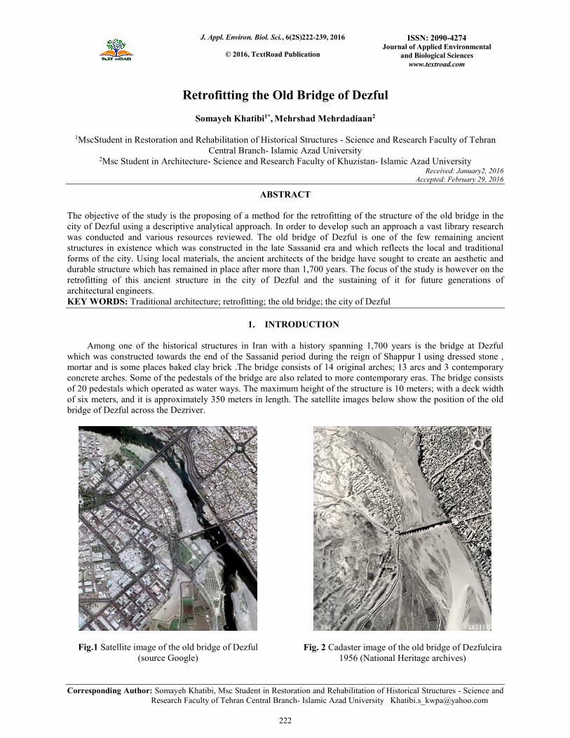
The figure below illustrates the general view of the old bridge's arrangement. The model has been scaled on the
basis of the measurements and pictures taken. Due to the sequential arrangement of the bridge's architectural
features and in order to be able to easily identify the various components the pedestals are marked with an A, the
arches with a B the arcs with a C.
A1 A2 A3 A4 A5 A6 A7 A8 A9 A10 A11 A12 A13 A14A15 A16 A17 A18 A19 A20
B1 B2 B3 B4 B5 B6 B7 B8 B9 B10 B11 B12 B13 B14 B15 B16 B17
C1C2 C3 C4 C5 C6 C7 C8 C9 C10
C11 C12 C13C11/1
Fig. 3 The arrangement of pedestals, arches and arcs in the old bridge of Dezful (source Dez Ab, 2011)
223
J. Appl. Environ. Biol. Sci., 6(2S)222-239, 2016
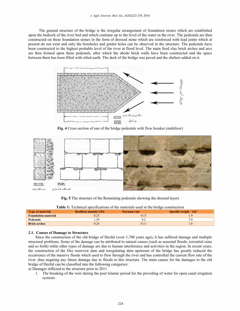
The general structure of the bridge is the irregular arrangement of foundation stones which are established
upon the bedrock of the river bed and which continue up to the level of the water in the river. The pedestals are then
constructed on these foundation stones in the form of dressed stone which are reinforced with lead joints which at
present do not exist and only the boreholes and gimlet holes can be observed in the structure. The pedestals have
been constructed to the highest probable level of the river at flood level. The main fired clay brick arches and arcs
are then formed upon these pedestals, after which the abode brick walls have been constructed and the space
between them has been filled with silted earth. The deck of the bridge was paved and the shelters added on it.
Fig. 4 Cross section of one of the bridge pedestals with flow breaker (stabilizer)
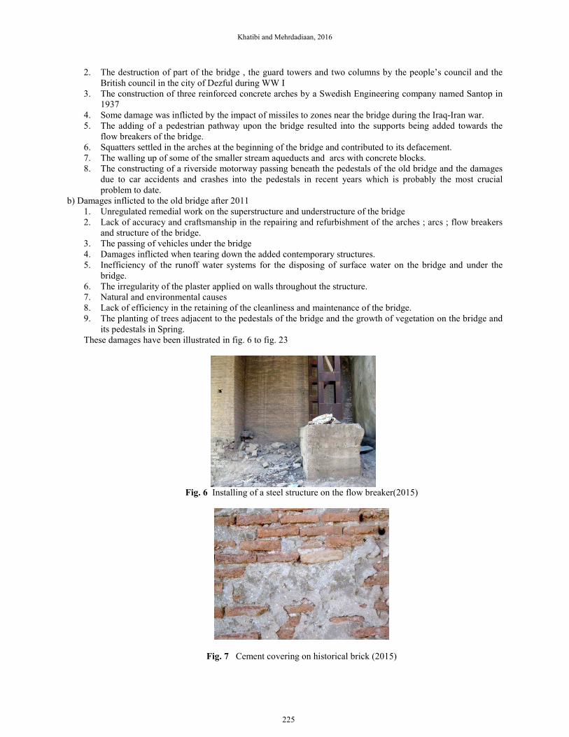
Fig. 5 The structure of the Remaining pedestals showing the dressed layers
Table 1: Technical specifications of the materials used in the bridge construction Type of material Resilient module GPa Pavason rate Specific weight t/m3
Foundation material 0.25 0.15 1.9
Pedestals 1.54 0.2 2.0
Brick arches 0.24 0.11 1.8
2.1. Causes of Damage to Structure
Since the construction of the old bridge of Dezful (over 1,700 years ago), it has suffered damage and multiple
structural problems. Some of the damage can be attributed to natural causes (such as seasonal floods; torrential rains
and so forth) while other types of damage are due to human interference and activities in the region. In recent years,
the construction of the Dez reservoir dam and reregulating dam upstream of the bridge has greatly reduced the
occurrence of the massive floods which used to flow through the river and has controlled the current flow rate of the
river ,thus negating any future damage due to floods to this structure. The main causes for the damages to the old
bridge of Dezful can be classified into the following categories:
a) Damages inflicted to the structure prior to 2011
1. The breaking of the weir during the post Islamic period for the providing of water for open canal irrigation
systems
224
Khatibi and Mehrdadiaan, 2016
2. The destruction of part of the bridge , the guard towers and two columns by the people’s council and the
British council in the city of Dezful during WW I
3. The construction of three reinforced concrete arches by a Swedish Engineering company named Santop in
1937
4. Some damage was inflicted by the impact of missiles to zones near the bridge during the Iraq-Iran war.
5. The adding of a pedestrian pathway upon the bridge resulted into the supports being added towards the
flow breakers of the bridge.
6. Squatters settled in the arches at the beginning of the bridge and contributed to its defacement.
7. The walling up of some of the smaller stream aqueducts and arcs with concrete blocks.
8. The constructing of a riverside motorway passing beneath the pedestals of the old bridge and the damages
due to car accidents and crashes into the pedestals in recent years which is probably the most crucial
problem to date.
b) Damages inflicted to the old bridge after 2011
1. Unregulated remedial work on the superstructure and understructure of the bridge
2. Lack of accuracy and craftsmanship in the repairing and refurbishment of the arches ; arcs ; flow breakers
and structure of the bridge.
3. The passing of vehicles under the bridge
4. Damages inflicted when tearing down the added contemporary structures.
5. Inefficiency of the runoff water systems for the disposing of surface water on the bridge and under the
bridge.
6. The irregularity of the plaster applied on walls throughout the structure.
7. Natural and environmental causes
8. Lack of efficiency in the retaining of the cleanliness and maintenance of the bridge.
9. The planting of trees adjacent to the pedestals of the bridge and the growth of vegetation on the bridge and
its pedestals in Spring.
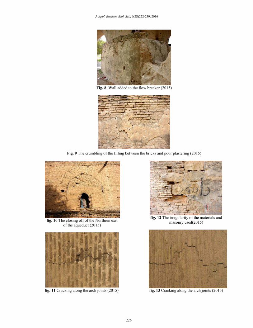
These damages have been illustrated in fig. 6 to fig. 23
Fig. 6 Installing of a steel structure on the flow breaker(2015)
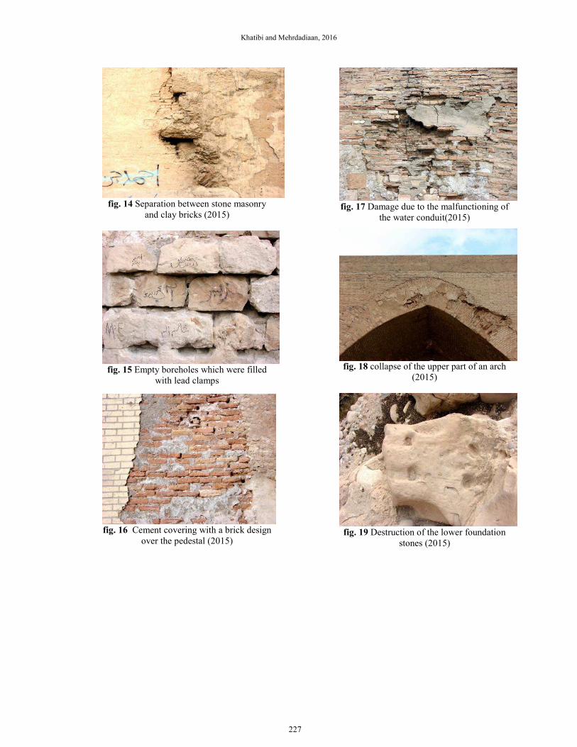
Fig. 7 Cement covering on historical brick (2015)
225
J. Appl. Environ. Biol. Sci., 6(2S)222-239, 2016
Fig. 8 Wall added to the flow breaker (2015)
Fig. 9 The crumbling of the filling between the bricks and poor plastering (2015)
fig. 10 The closing off of the Northern exit
of the aqueduct (2015)
fig. 12 The irregularity of the materials and
masonry used(2015)
fig. 11 Cracking along the arch joints (2015) fig. 13 Cracking along the arch joints (2015)
226
Khatibi and Mehrdadiaan, 2016
fig. 14 Separation between stone masonry
and clay bricks (2015)
fig. 15 Empty boreholes which were filled
with lead clamps
fig. 16 Cement covering with a brick design
over the pedestal (2015)
fig. 17 Damage due to the malfunctioning of
the water conduit(2015)
fig. 18 collapse of the upper part of an arch
(2015)
fig. 19 Destruction of the lower foundation
stones (2015)
227
J. Appl. Environ. Biol. Sci., 6(2S)222-239, 2016
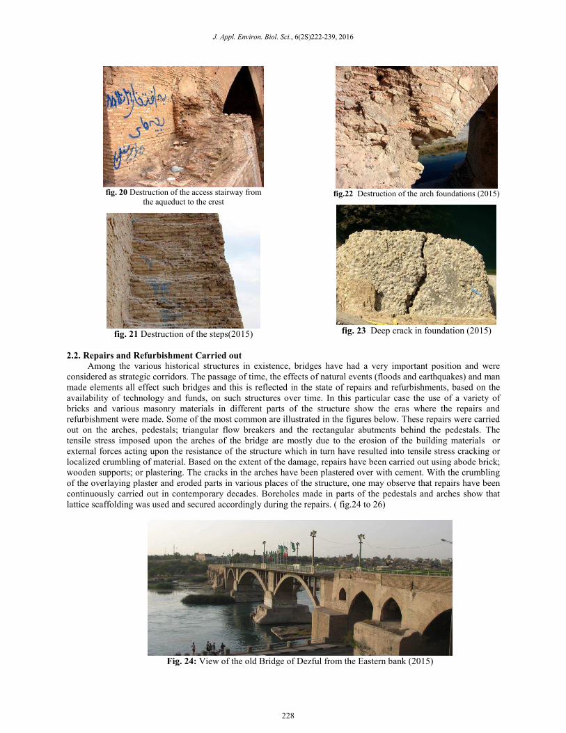
fig. 20 Destruction of the access stairway from
the aqueduct to the crest
fig. 21 Destruction of the steps(2015)
fig.22 Destruction of the arch foundations (2015)
fig. 23 Deep crack in foundation (2015)
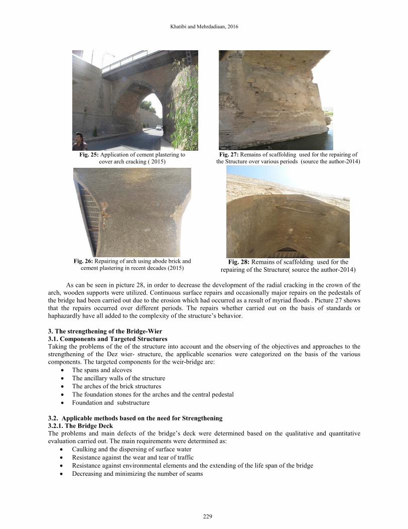
2.2. Repairs and Refurbishment Carried out
Among the various historical structures in existence, bridges have had a very important position and were
considered as strategic corridors. The passage of time, the effects of natural events (floods and earthquakes) and man
made elements all effect such bridges and this is reflected in the state of repairs and refurbishments, based on the
availability of technology and funds, on such structures over time. In this particular case the use of a variety of
bricks and various masonry materials in different parts of the structure show the eras where the repairs and
refurbishment were made. Some of the most common are illustrated in the figures below. These repairs were carried
out on the arches, pedestals; triangular flow breakers and the rectangular abutments behind the pedestals. The
tensile stress imposed upon the arches of the bridge are mostly due to the erosion of the building materials or
external forces acting upon the resistance of the structure which in turn have resulted into tensile stress cracking or
localized crumbling of material. Based on the extent of the damage, repairs have been carried out using abode brick;
wooden supports; or plastering. The cracks in the arches have been plastered over with cement. With the crumbling
of the overlaying plaster and eroded parts in various places of the structure, one may observe that repairs have been
continuously carried out in contemporary decades. Boreholes made in parts of the pedestals and arches show that
lattice scaffolding was used and secured accordingly during the repairs. ( fig.24 to 26)
Fig. 24: View of the old Bridge of Dezful from the Eastern bank (2015)
228
Khatibi and Mehrdadiaan, 2016
Fig. 25: Application of cement plastering to
cover arch cracking ( 2015)
Fig. 26: Repairing of arch using abode brick and
cement plastering in recent decades (2015)
Fig. 27: Remains of scaffolding used for the repairing of
the Structure over various periods (source the author-2014)
Fig. 28: Remains of scaffolding used for the
repairing of the Structure( source the author-2014)
As can be seen in picture 28, in order to decrease the development of the radial cracking in the crown of the
arch, wooden supports were utilized. Continuous surface repairs and occasionally major repairs on the pedestals of
the bridge had been carried out due to the erosion which had occurred as a result of myriad floods . Picture 27 shows
that the repairs occurred over different periods. The repairs whether carried out on the basis of standards or
haphazardly have all added to the complexity of the structure’s behavior.
3. The strengthening of the Bridge-Wier
3.1. Components and Targeted Structures
Taking the problems of the of the structure into account and the observing of the objectives and approaches to the
strengthening of the Dez wier- structure, the applicable scenarios were categorized on the basis of the various
components. The targeted components for the weir-bridge are:
• The spans and alcoves
• The ancillary walls of the structure
• The arches of the brick structures
• The foundation stones for the arches and the central pedestal
• Foundation and substructure
3.2. Applicable methods based on the need for Strengthening
3.2.1. The Bridge Deck
The problems and main defects of the bridge’s deck were determined based on the qualitative and quantitative
evaluation carried out. The main requirements were determined as:
• Caulking and the dispersing of surface water
• Resistance against the wear and tear of traffic
• Resistance against environmental elements and the extending of the life span of the bridge
• Decreasing and minimizing the number of seams
229
J. Appl. Environ. Biol. Sci., 6(2S)222-239, 2016
• Maximizing the amount of energy absorbed
Weight Unloading
The deck of any bridge should be built of durable materials to withstand the erosion resulting from the extent of
traffic on the bridge, the draining of rainwater and climate changes. In addition it should be able to safely and
effectively distribute the loads imposed upon it to the underlying arches and subsequently the pedestals beneath
itself. One method of doing so is the utilizing of thin reinforced concrete slabs (Fr.dalle’) since the use of
unreinforced material is not effective in the transferring of the weight of the traffic upon the deck of the bridge to the
crown of the arch. Using modern architectural techniques or using a thin covering of stone material over the
reinforced concrete slab, it is possible to retain the appearance of the deck. It is believed that the best paving
material for the deck would be a polymer composite concrete covering. This will be further elaborated on below.
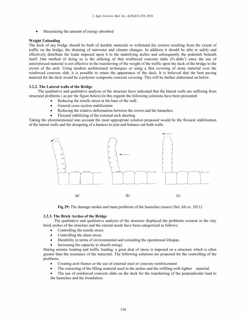
3.2.2. The Lateral walls of the Bridge
The qualitative and qualitative analysis of the structure have indicated that the lateral walls are suffering from
structural problems ( as per the figure below).In this regards the following solutions have been presented:
• Reducing the tensile stress at the base of the wall.
• General cross section stabilization
• Reducing the relative deformation between the crown and the haunches.
• Flexural stabilizing of the external arch sheeting
Taking the aforementioned into account the most appropriate solution proposed would be the flexural stabilization
of the lateral walls and the designing of a harness to join and balance out both walls.
Fig 29: The damage modes and main problems of the haunches (source Dez Ab co. 2011)
3.2.3. The Brick Arches of the Bridge
The qualitative and qualitative analysis of the structure displayed the problems existent in the clay
brick arches of the structure and the current needs have been categorized as follows:
• Controlling the tensile stress
• Controlling the shear stress
• Durability in terms of environmental and extending the operational lifespan.
• Increasing the capacity to absorb energy.
During seismic loading and traffic loading, a great deal of stress is imposed on a structure which is often
greater than the resistance of the materials. The following solutions are proposed for the controlling of the
problems:
• Creating arch frames or the use of external steel or concrete reinforcement
• The extracting of the filling material used in the arches and the refilling with lighter material.
• The use of reinforced concrete slabs on the deck for the transferring of the perpendicular load to
the haunches and the foundation.
230
Khatibi and Mehrdadiaan, 2016
• Using internal reinforced concrete arches for the transferring of the perpendicular load to the
haunches and the foundation.
• Reinforcing the pedestals and the preventing of transferring the seismic load of the pedestals and
deck to the arches.
• Surface reinforcement using cable , FRP or steel rods
• Subsurface reinforcement
• Grouting using upgraded mortar.
These solutions have not been proposed on the basis of historical and architectural reasons. It is believed that
the best solution for arch reinforcement in this particular case is the utilizing of sub structural reinforcement .In this
method by creating regular groves and embedding the reinforcement rebars, the necessary reinforcement for
flexural, shear and tensile stress and the controlling of cracking will be provided; what more, once embedded, the
reinforcing rebars are covered with a suitable coating material which will also be used to cover the existing cracks
also. The reinforcing rebars should have the same structural density of the materials used in the structure, thus not
just any type of steel rebar or FRP can be used. In addition the grouting material used must have the same
combination and density of the existing filling material in as such that it would be compatible both in terms of its
chemical and physical composition to the whole structure. The type of rebar used for stone and clay brick structures
varies in extent, but it has been applied widely on a global scale for the restoration and refurbishment of historically
important structures. This can be best exemplified by the restoration of the medieval Langley castle in
Northumberland. The unique medieval structure which was constructed in the 14th century is over 600 years old and
is currently operating as a luxury hotel. Although the structure has been well retained , various displacements over
the centuries have caused cracking on the external masonry. The use of special internal steel rebars for the
stabilizing of the structure and the retaining of the exterior of the castle was selected as being the most suitable
option, thus the castle was safely and efficiently restored; what more, even normal displacement did not impose any
stress on the said structure. Since the underlying surface for the rebars was uneven and in order to retain the external
rock face of the castle, some of the groves had to be cut manually in the space between the stone and sandstone
blocks joints. The rebars which were then adapted for such groves were inserted and grouted using Helibond. Single
and double rebars totaling approximately 400 meters in length were then inserted at various heights. These created
lateral harnessing and minimized future cracking. A lime coating was than applied to the walls to retain its
originality and to protect the structure.
Another example was a retaining wall built in the 19th century in Hope square in the city of Bristol which
was over 100 meters in length and 2.7 meters in height. The wall is located in proximity to Hope Chapel Hill and a
narrow pedestrian walk path parallels the wall. The pressure of the earth on one side of the wall had caused it to
bulge outwards and created vertical cracks on the wall.
In order to reinforce the wall, mechanical restrainers were installed within the walls . Two special steel rebars
were then inserted in the corners of the walls with 450 mm spacing, extending along its length for five meters and
embedded in a bed of grout. This caused a reinforcing of the vertical cracks and the creating of structural skeins
along the wall, thus reinforcing the wall itself.
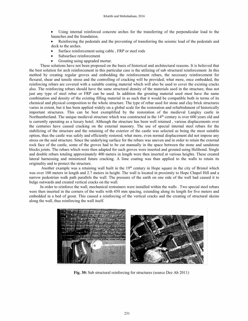
Fig. 30: Sub structural reinforcing for structures (source Dez Ab 2011)
231
J. Appl. Environ. Biol. Sci., 6(2S)222-239, 2016
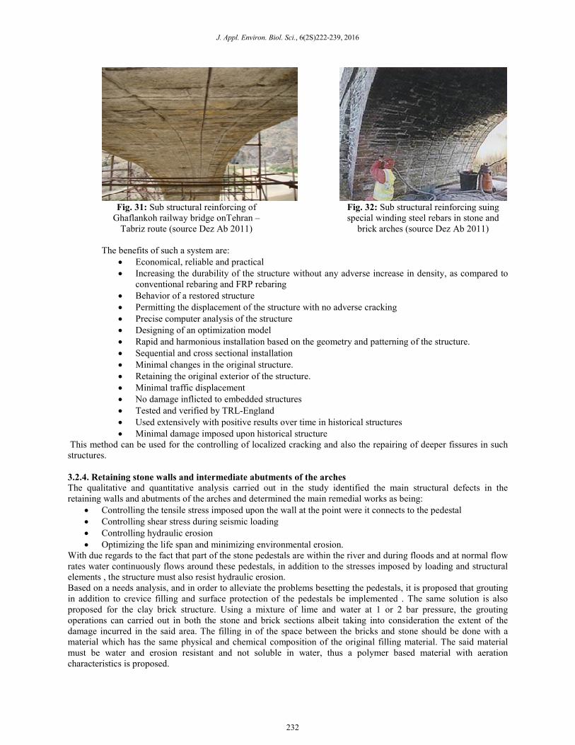
Fig. 31: Sub structural reinforcing of
Ghaflankoh railway bridge onTehran –
Tabriz route (source Dez Ab 2011)
Fig. 32: Sub structural reinforcing suing
special winding steel rebars in stone and
brick arches (source Dez Ab 2011)
The benefits of such a system are:
• Economical, reliable and practical
• Increasing the durability of the structure without any adverse increase in density, as compared to
conventional rebaring and FRP rebaring
• Behavior of a restored structure
• Permitting the displacement of the structure with no adverse cracking
• Precise computer analysis of the structure
• Designing of an optimization model
• Rapid and harmonious installation based on the geometry and patterning of the structure.
• Sequential and cross sectional installation
• Minimal changes in the original structure.
• Retaining the original exterior of the structure.
• Minimal traffic displacement
• No damage inflicted to embedded structures
• Tested and verified by TRL-England
• Used extensively with positive results over time in historical structures
• Minimal damage imposed upon historical structure
This method can be used for the controlling of localized cracking and also the repairing of deeper fissures in such
structures.
3.2.4. Retaining stone walls and intermediate abutments of the arches
The qualitative and quantitative analysis carried out in the study identified the main structural defects in the
retaining walls and abutments of the arches and determined the main remedial works as being:
• Controlling the tensile stress imposed upon the wall at the point were it connects to the pedestal
• Controlling shear stress during seismic loading
• Controlling hydraulic erosion
• Optimizing the life span and minimizing environmental erosion.
With due regards to the fact that part of the stone pedestals are within the river and during floods and at normal flow
rates water continuously flows around these pedestals, in addition to the stresses imposed by loading and structural
elements , the structure must also resist hydraulic erosion.
Based on a needs analysis, and in order to alleviate the problems besetting the pedestals, it is proposed that grouting
in addition to crevice filling and surface protection of the pedestals be implemented . The same solution is also
proposed for the clay brick structure. Using a mixture of lime and water at 1 or 2 bar pressure, the grouting
operations can carried out in both the stone and brick sections albeit taking into consideration the extent of the
damage incurred in the said area. The filling in of the space between the bricks and stone should be done with a
material which has the same physical and chemical composition of the original filling material. The said material
must be water and erosion resistant and not soluble in water, thus a polymer based material with aeration
characteristics is proposed.
232
Khatibi and Mehrdadiaan, 2016
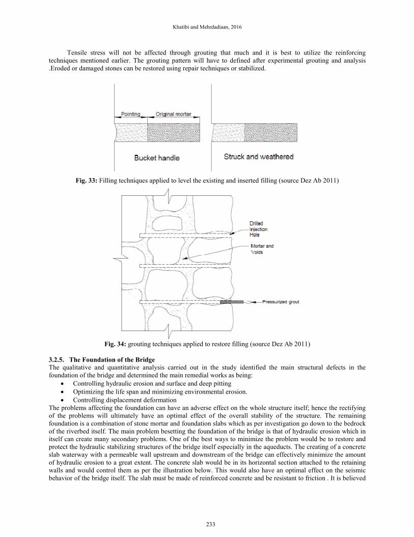
Tensile stress will not be affected through grouting that much and it is best to utilize the reinforcing
techniques mentioned earlier. The grouting pattern will have to defined after experimental grouting and analysis
.Eroded or damaged stones can be restored using repair techniques or stabilized.
Fig. 33: Filling techniques applied to level the existing and inserted filling (source Dez Ab 2011)
Fig. 34: grouting techniques applied to restore filling (source Dez Ab 2011)
3.2.5. The Foundation of the Bridge
The qualitative and quantitative analysis carried out in the study identified the main structural defects in the
foundation of the bridge and determined the main remedial works as being:
• Controlling hydraulic erosion and surface and deep pitting
• Optimizing the life span and minimizing environmental erosion.
• Controlling displacement deformation
The problems affecting the foundation can have an adverse effect on the whole structure itself; hence the rectifying
of the problems will ultimately have an optimal effect of the overall stability of the structure. The remaining
foundation is a combination of stone mortar and foundation slabs which as per investigation go down to the bedrock
of the riverbed itself. The main problem besetting the foundation of the bridge is that of hydraulic erosion which in
itself can create many secondary problems. One of the best ways to minimize the problem would be to restore and
protect the hydraulic stabilizing structures of the bridge itself especially in the aqueducts. The creating of a concrete
slab waterway with a permeable wall upstream and downstream of the bridge can effectively minimize the amount
of hydraulic erosion to a great extent. The concrete slab would be in its horizontal section attached to the retaining
walls and would control them as per the illustration below. This would also have an optimal effect on the seismic
behavior of the bridge itself. The slab must be made of reinforced concrete and be resistant to friction . It is believed
233
J. Appl. Environ. Biol. Sci., 6(2S)222-239, 2016
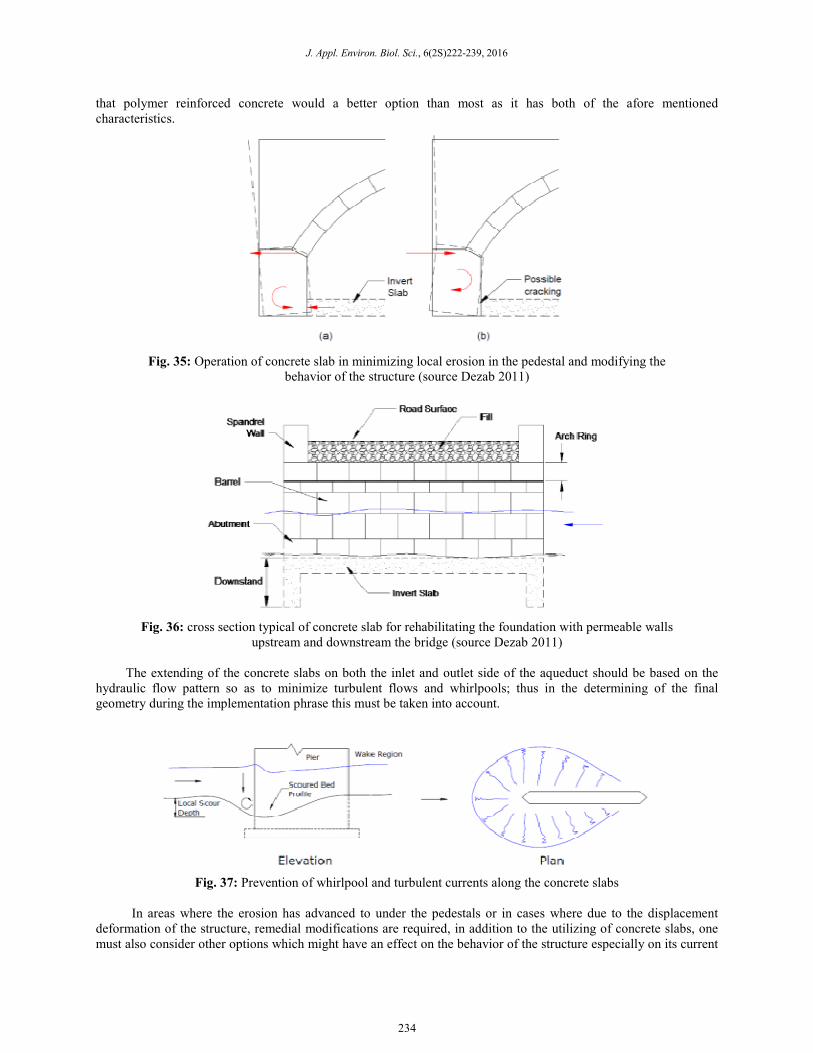
that polymer reinforced concrete would a better option than most as it has both of the afore mentioned
characteristics.
Fig. 35: Operation of concrete slab in minimizing local erosion in the pedestal and modifying the
behavior of the structure (source Dezab 2011)
Fig. 36: cross section typical of concrete slab for rehabilitating the foundation with permeable walls
upstream and downstream the bridge (source Dezab 2011)
The extending of the concrete slabs on both the inlet and outlet side of the aqueduct should be based on the
hydraulic flow pattern so as to minimize turbulent flows and whirlpools; thus in the determining of the final
geometry during the implementation phrase this must be taken into account.
Fig. 37: Prevention of whirlpool and turbulent currents along the concrete slabs
In areas where the erosion has advanced to under the pedestals or in cases where due to the displacement
deformation of the structure, remedial modifications are required, in addition to the utilizing of concrete slabs, one
must also consider other options which might have an effect on the behavior of the structure especially on its current
234
Khatibi and Mehrdadiaan, 2016
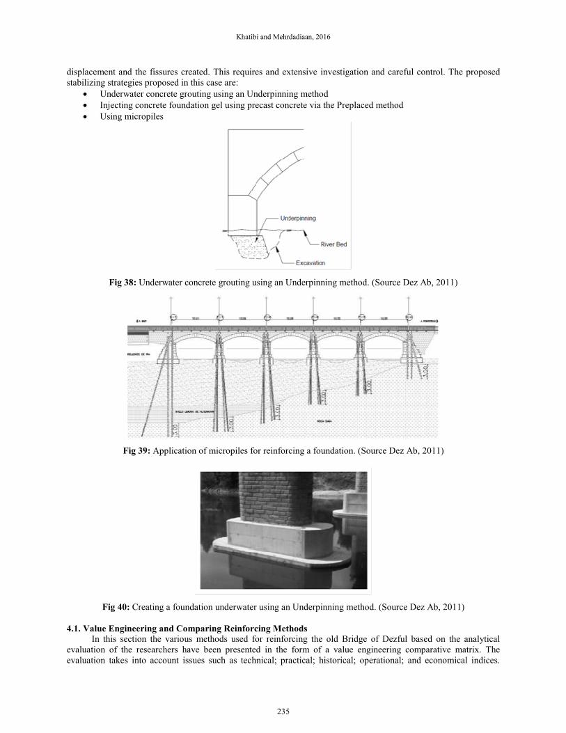
displacement and the fissures created. This requires and extensive investigation and careful control. The proposed
stabilizing strategies proposed in this case are:
• Underwater concrete grouting using an Underpinning method
• Injecting concrete foundation gel using precast concrete via the Preplaced method
• Using micropiles
Fig 38: Underwater concrete grouting using an Underpinning method. (Source Dez Ab, 2011)
Fig 39: Application of micropiles for reinforcing a foundation. (Source Dez Ab, 2011)
Fig 40: Creating a foundation underwater using an Underpinning method. (Source Dez Ab, 2011)
4.1. Value Engineering and Comparing Reinforcing Methods
In this section the various methods used for reinforcing the old Bridge of Dezful based on the analytical
evaluation of the researchers have been presented in the form of a value engineering comparative matrix. The
evaluation takes into account issues such as technical; practical; historical; operational; and economical indices.
235
J. Appl. Environ. Biol. Sci., 6(2S)222-239, 2016
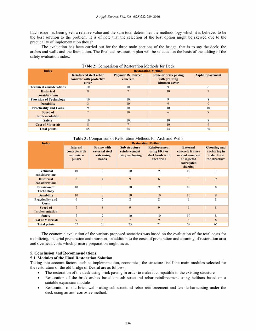
Each issue has been given a relative value and the sum total determines the methodology which it is believed to be
the best solution to the problem. It is of note that the selection of the best option might be skewed due to the
practicality of implementation though.
The evaluation has been carried out for the three main sections of the bridge, that is to say the deck; the
arches and walls and the foundation. The finalized restoration plan will be selected on the basis of the adding of the
safety evaluation index.
Table 2: Comparison of Restoration Methods for Deck Index Restoration Method
Reinforced steel rebar
concrete with protective
cover
Polymer Reinforced
concrete
Stone or brick paving
with grouting
Bitumen cover
Asphalt pavement
Technical considerations 10 10 9 6
Historical
considerations
8 7 10 7
Provision of Technology 10 10 9 8
Durability 3 10 9 9
Practicality and Costs 9 10 10 10
Speed of
Implementation
7 10 6 9
Safety 10 10 10 8
Cost of Materials 8 7 10 9
Total points 65 74 74 66
Table 3: Comparison of Restoration Methods for Arch and Walls Index Restoration Method
Internal
concrete arch
and micro
pillars
Frame with
external steel
restraining
bands
Sub structure
reinforcement
using anchoring
Reinforcement
using FRP or
steel bands with
anchoring
External
concrete frames
or shot concrete
or injected
corrugated
sheeting
Grouting and
anchoring in
order to tie
the structure
Technical
considerations
10 9 10 9 10 7
Historical
considerations
8 4 9 6 3 9
Provision of
Technology
10 9 10 9 10 8
Durability 10 8 10 10 10 9
Practicality and
Costs
6 7 8 8 9 8
Speed of
Implementation
7 8 9 9 9 8
Safety 7 7 10 10 10 8
Cost of Materials 9 8 7 9 8 8
Total points 67 70 73 71 69 65
The economic evaluation of the various proposed scenarios was based on the evaluation of the total costs for
mobilizing, material preparation and transport; in addition to the costs of preparation and cleaning of restoration area
and overhead costs which primary preparation might incur.
5. Conclusion and Recommendations:
5.1. Modules of the Final Restoration Solution
Taking into account factors such as implementation, economics; the structure itself the main modules selected for
the restoration of the old bridge of Dezful are as follows:
• The restoration of the deck using brick paving in order to make it compatible to the existing structure
• Restoration of the brick arches based on sub structural rebar reinforcement using helibars based on a
suitable expansion module
• Restoration of the brick walls using sub structural rebar reinforcement and tensile harnessing under the
deck using an anti-corrosive method.
236
Khatibi and Mehrdadiaan, 2016
• Restoration of the stone pedestals using localized stitching via self drilling, along with Shell grouting and
filling the crevices between the stones.
• Restoration of the foundation using underwater restoration techniques or beneath the eroded areas using
Underpinning and localized reinforcement
• Minimizing of Hydraulic erosion using polymer reinforced or rebar reinforced concrete slabs with short
cutoffs and with anti-friction characteristics.
5.2. Technical and Operational Specifications and Evaluation of Material
5.2.1. Surface of The Deck and Walls
The best option for the restoration of this section includes a stone structure; along with a specialized mortar having a
lime base and shell grouting using a grout such as limepore. The stone used will be of the same type used in the
original structure and all historical and architectural considerations will be taken into account.
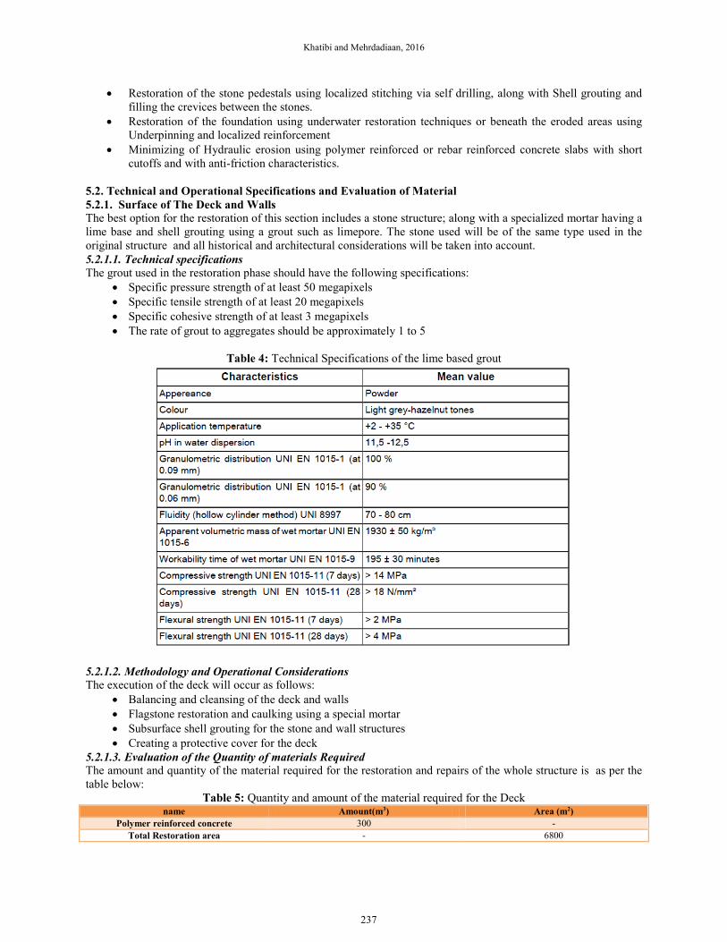
5.2.1.1. Technical specifications
The grout used in the restoration phase should have the following specifications:
• Specific pressure strength of at least 50 megapixels
• Specific tensile strength of at least 20 megapixels
• Specific cohesive strength of at least 3 megapixels
• The rate of grout to aggregates should be approximately 1 to 5
Table 4: Technical Specifications of the lime based grout
5.2.1.2. Methodology and Operational Considerations
The execution of the deck will occur as follows:
• Balancing and cleansing of the deck and walls
• Flagstone restoration and caulking using a special mortar
• Subsurface shell grouting for the stone and wall structures
• Creating a protective cover for the deck
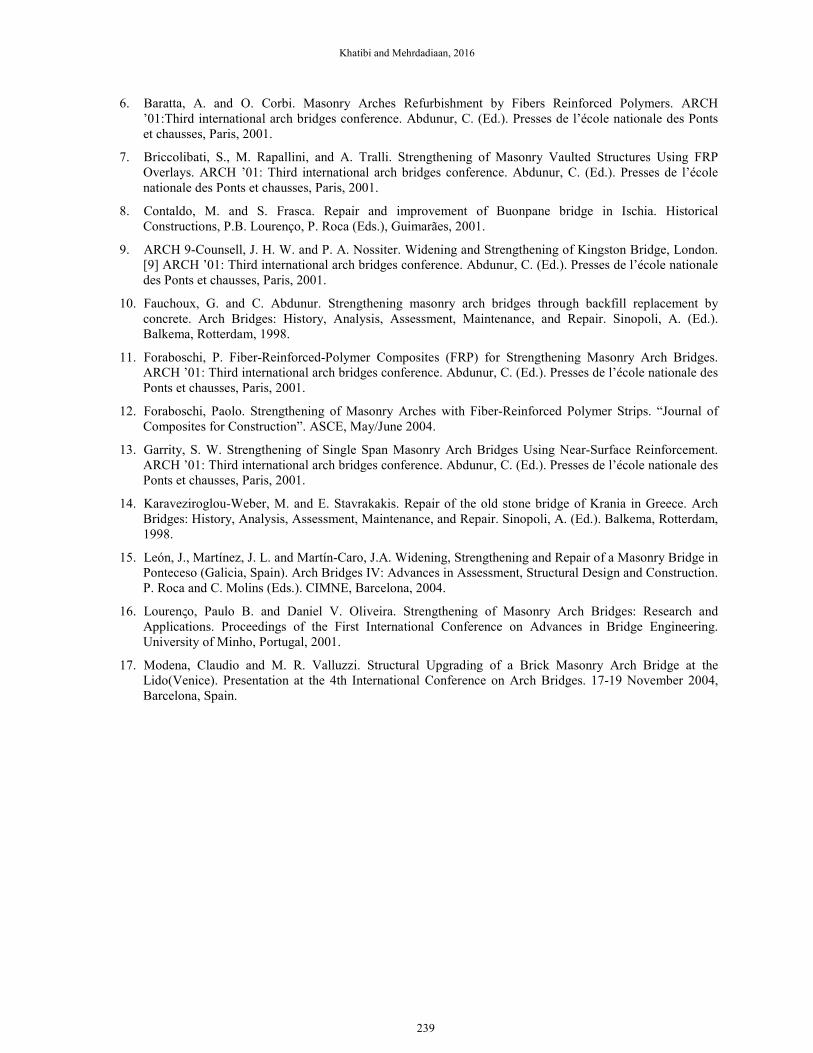
5.2.1.3. Evaluation of the Quantity of materials Required
The amount and quantity of the material required for the restoration and repairs of the whole structure is as per the
table below:
Table 5: Quantity and amount of the material required for the Deck name Amount(m3) Area (m2)
Polymer reinforced concrete 300 -
Total Restoration area - 6800
237
J. Appl. Environ. Biol. Sci., 6(2S)222-239, 2016
5.2.2. The Foundation and Substructure
5.2.2.1. Technical Specifications
The concrete and rebars used will have the following specifications:
• The concrete will have a specific pressure strength of 28 days as per a cylindrical model of 30 megapixels
and will be compatible with the original mortar of the structure. The type of cement will be a type II cement
with a separating sleeve.
• A III rebar will be used for all embedded structures beneath the walls and abutements with a specific
concurrent strength of 400 megapixels
• The depth of the concrete over the rebar will be 75 mm
• The concrete slab at the bottom will be made of polymer reinforced concrete with a specific pressure
strength of 28 days as per a cylindrical model of 35 megapixels using a cement type II and polyolphin
polymers of 4 kg/m3 at a depth of 20 cm.
• The type of concrete used will be off a self compacting polymer SCC type with durability elements added
such as MCI for the alleviating of corrosion and a special facilitator to control the slump and attain the
required operational conditions.
• The electrical resistance for the concrete used in the structure should be at least 20 kilohms/cm
• The permeability of the self compacting concrete should be 10-10 m/s in order to meet the durability factor
The concrete used under water should have the following specifications:
• Self compacting
• Resistant to being washed away during pouring
• Having a controlled curing period
• Having minimal hydration and water logging
• Having a strong cohesive strength in the required sectors
• For the covering of the bottom concrete slab , and with due regards to the creating of a strong resistance for
friction and erosion due to water flow, polymer reinforced concrete will be used.
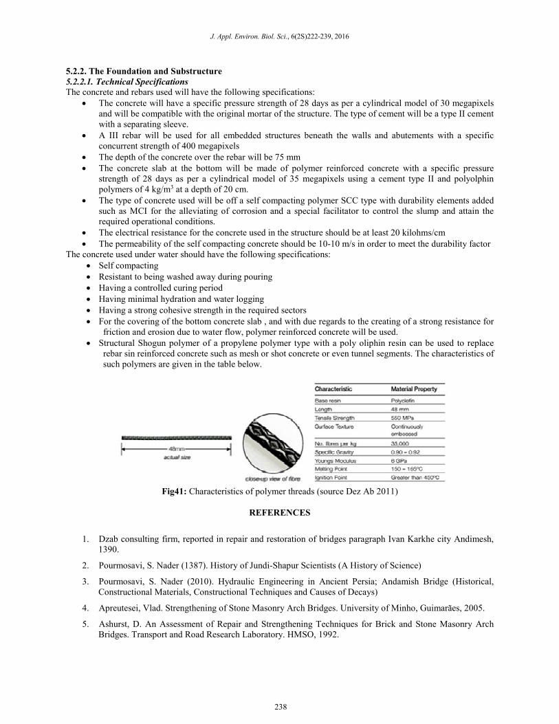
• Structural Shogun polymer of a propylene polymer type with a poly oliphin resin can be used to replace
rebar sin reinforced concrete such as mesh or shot concrete or even tunnel segments. The characteristics of
such polymers are given in the table below.
Fig41: Characteristics of polymer threads (source Dez Ab 2011)
REFERENCES
1. Dzab consulting firm, reported in repair and restoration of bridges paragraph Ivan Karkhe city Andimesh,
1390.
2. Pourmosavi, S. Nader (1387). History of Jundi-Shapur Scientists (A History of Science)
3. Pourmosavi, S. Nader (2010). Hydraulic Engineering in Ancient Persia; Andamish Bridge (Historical,
Constructional Materials, Constructional Techniques and Causes of Decays)
4. Apreutesei, Vlad. Strengthening of Stone Masonry Arch Bridges. University of Minho, Guimarães, 2005.
5. Ashurst, D. An Assessment of Repair and Strengthening Techniques for Brick and Stone Masonry Arch
Bridges. Transport and Road Research Laboratory. HMSO, 1992.
238
Khatibi and Mehrdadiaan, 2016
6. Baratta, A. and O. Corbi. Masonry Arches Refurbishment by Fibers Reinforced Polymers. ARCH
’01:Third international arch bridges conference. Abdunur, C. (Ed.). Presses de l’école nationale des Ponts
et chausses, Paris, 2001.
7. Briccolibati, S., M. Rapallini, and A. Tralli. Strengthening of Masonry Vaulted Structures Using FRP
Overlays. ARCH ’01: Third international arch bridges conference. Abdunur, C. (Ed.). Presses de l’école
nationale des Ponts et chausses, Paris, 2001.
8. Contaldo, M. and S. Frasca. Repair and improvement of Buonpane bridge in Ischia. Historical
Constructions, P.B. Lourenço, P. Roca (Eds.), Guimarães, 2001.
9. ARCH 9-Counsell, J. H. W. and P. A. Nossiter. Widening and Strengthening of Kingston Bridge, London.
[9] ARCH ’01: Third international arch bridges conference. Abdunur, C. (Ed.). Presses de l’école nationale
des Ponts et chausses, Paris, 2001.
10. Fauchoux, G. and C. Abdunur. Strengthening masonry arch bridges through backfill replacement by
concrete. Arch Bridges: History, Analysis, Assessment, Maintenance, and Repair. Sinopoli, A. (Ed.).
Balkema, Rotterdam, 1998.
11. Foraboschi, P. Fiber-Reinforced-Polymer Composites (FRP) for Strengthening Masonry Arch Bridges.
ARCH ’01: Third international arch bridges conference. Abdunur, C. (Ed.). Presses de l’école nationale des
Ponts et chausses, Paris, 2001.
12. Foraboschi, Paolo. Strengthening of Masonry Arches with Fiber-Reinforced Polymer Strips. “Journal of
Composites for Construction”. ASCE, May/June 2004.
13. Garrity, S. W. Strengthening of Single Span Masonry Arch Bridges Using Near-Surface Reinforcement.
ARCH ’01: Third international arch bridges conference. Abdunur, C. (Ed.). Presses de l’école nationale des
Ponts et chausses, Paris, 2001.
14. Karaveziroglou-Weber, M. and E. Stavrakakis. Repair of the old stone bridge of Krania in Greece. Arch
Bridges: History, Analysis, Assessment, Maintenance, and Repair. Sinopoli, A. (Ed.). Balkema, Rotterdam,
1998.
15. León, J., Martínez, J. L. and Martín-Caro, J.A. Widening, Strengthening and Repair of a Masonry Bridge in
Ponteceso (Galicia, Spain). Arch Bridges IV: Advances in Assessment, Structural Design and Construction.
P. Roca and C. Molins (Eds.). CIMNE, Barcelona, 2004.
16. Lourenςo, Paulo B. and Daniel V. Oliveira. Strengthening of Masonry Arch Bridges: Research and
Applications. Proceedings of the First International Conference on Advances in Bridge Engineering.
University of Minho, Portugal, 2001.
17. Modena, Claudio and M. R. Valluzzi. Structural Upgrading of a Brick Masonry Arch Bridge at the
Lido(Venice). Presentation at the 4th International Conference on Arch Bridges. 17-19 November 2004,
Barcelona, Spain.
239