Embed Size (px)
Citation preview
Page 1
Installation Support:Marygrove Retractable Awnings
734-422-7110 [email protected]
IT IS VERY IMPORTANT TO READ THIS MANUAL IN IT’S ENTIRETY. FAILURE TO FOLLOW THE
INSTRUCTIONS IN THIS INSTALLATION MANUAL MAY RESULT IN PERSONAL INJURY
Retractable AwningInstallation Manual
Page 2
We thank you for your purchase of your Marygrove retractable awning. Marygrove awnings will give your family the shade and protection you need on your deck or patio. You can now look forward to months of enjoyment and memories.
Before you begin installation, take a moment to familiarize yourself with the awning and this Owner’sManual. Please check to insure all of the parts listed on page 5 have been included with your awning and that you have the correct size, frame and fabric. If you ordered an optional mounting type make sure you have those parts. They are listed on page 5.
Installation of your Awning
When unpacking your awning, take care to protect the awning from accidental damage or soiling. Do not drop or drag the awning on the ground.
Note: When removing the clear protective wrap from the awning, do not use a knife or box cutter to cut plastic wrap as you could accidentally slice into your awning fabric.
Note: Your awning has been shipped to you fully assembled but it is important to follow this instruction manual to securely fasten the mounting brackets to your home and install the awning. Please read these instructions completely before installing your awning. Please note, you will need a helper for installation. Left and Right references are as you are facing the house. You have been provided with the proper fasteners for mounting to your wall surface.
For the greatest enjoyment of your lateral arm awning, please mount as high on your wall as possible, with a recommended mounting height of 9’. Your awning is a motorized model and your electrical cord will allow you 16’ to reach your GFI outlet. You will find your remote included in your box.
Operating your AwningNote: If you purchased a 20’ awning, please review the CAUTION on page 18, under “Test for Proper Operation” before using your awning. Your awning, once installed, has the ability to be opened partially or to its full projection to suit your deck or patio design. The pitch of your awning may be easily adjusted, up or down, from the factory setting based upon your actual mounting height. Please see page 19, if you would like to make this adjustment.
Note: Please follow the Care and Maintenance Guidelines on pages 21 to 24 for proper use and inclement weather precautions.
Please retain your Owner’s Manual and Installation Instructions for future reference regarding operation, care and maintenance, troubleshooting, customer service and warranty information.
Customer SupportMarygrove Retractable Awnings • 734-422-7110 [email protected] know that you will enjoy your Marygrove retractable awning by spending more time outside on your deck or patio.
Page 3
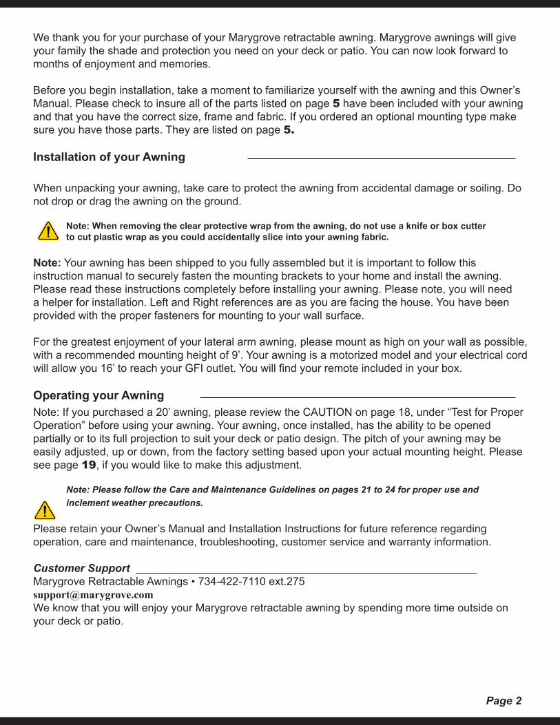
Recommended Tool List
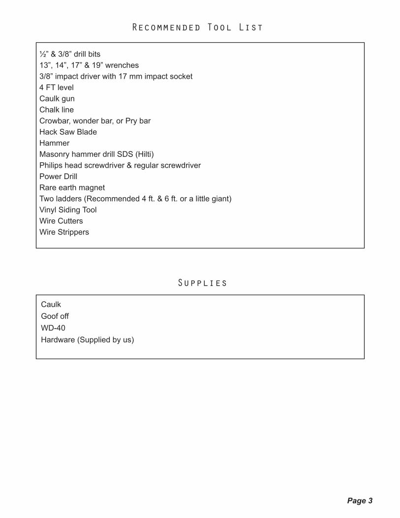
Supplies
CaulkGoof off WD-40Hardware (Supplied by us)
½” & 3/8” drill bits13”, 14”, 17” & 19” wrenches3/8” impact driver with 17 mm impact socket4 FT levelCaulk gunChalk lineCrowbar, wonder bar, or Pry barHack Saw BladeHammerMasonry hammer drill SDS (Hilti)Philips head screwdriver & regular screwdriverPower DrillRare earth magnetTwo ladders (Recommended 4 ft. & 6 ft. or a little giant)Vinyl Siding ToolWire CuttersWire Strippers
Page 4
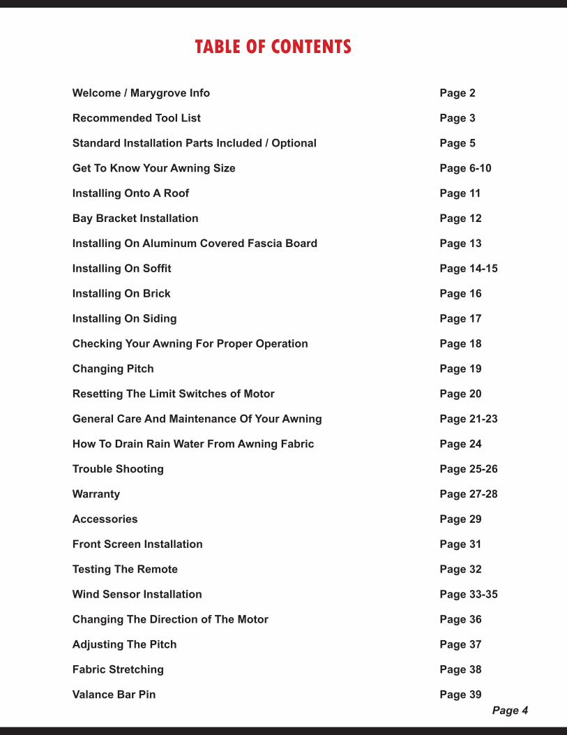
TABLE OF CONTENTS
Welcome / Marygrove Info Page 2
Recommended Tool List Page 3
Standard Installation Parts Included / Optional Page 5
Get To Know Your Awning Size Page 6-10
Installing Onto A Roof Page 11
Bay Bracket Installation Page 12
Installing On Aluminum Covered Fascia Board Page 13
Installing On Soffit Page 14-15
Installing On Brick Page 16
Installing On Siding Page 17
Checking Your Awning For Proper Operation Page 18
Changing Pitch Page 19
Resetting The Limit Switches of Motor Page 20
General Care And Maintenance Of Your Awning Page 21-23
How To Drain Rain Water From Awning Fabric Page 24
Trouble Shooting Page 25-26
Warranty Page 27-28
Accessories Page 29
Front Screen Installation Page 31
Testing The Remote Page 32
Wind Sensor Installation Page 33-35
Changing The Direction of The Motor Page 36
Adjusting The Pitch Page 37
Fabric Stretching Page 38
Valance Bar Pin Page 39
Page 5
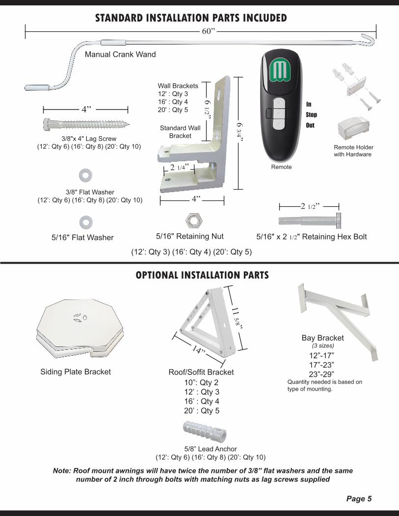
STANDARD INSTALLATION PARTS INCLUDED
Manual Crank Wand
Wall Brackets12' : Qty 316' : Qty 420' : Qty 5
3/8"x 4" Lag Screw(12’: Qty 6) (16’: Qty 8) (20’: Qty 10)
3/8" Flat Washer(12’: Qty 6) (16’: Qty 8) (20’: Qty 10)
5/16" Flat Washer 5/16" Retaining Nut 5/16" x 2 1/2" Retaining Hex Bolt
(12’: Qty 3) (16’: Qty 4) (20’: Qty 5)
Note: Roof mount awnings will have twice the number of 3/8” flat washers and the same number of 2 inch through bolts with matching nuts as lag screws supplied
Standard WallBracket
Remote Holderwith Hardware
Siding Plate Bracket
StopOut
In
Remote
Bay Bracket
OPTIONAL INSTALLATION PARTS
10”: Qty 212’ : Qty 316’ : Qty 420’ : Qty 5
Roof/Soffit BracketQuantity needed is based on type of mounting.
60”
4”
6 3/4” 2 1/4”
6 1/2”
5/8” Lead Anchor(12’: Qty 6) (16’: Qty 8) (20’: Qty 10)
11 5/8”
14” 12”-17”17”-23”23”-29”
(3 sizes)
4”
2 1/2”
Page 6
WARNING: FAILURE TO FOLLOW THESE INSTRUCTIONS COULD RESULT IN PERSONAL INJURY!
WARNING: Never attempt to repair or disassemble any part of the awning without following replacement part procedures supplied by the manufacturer. Trying to do so without proper instructions could result in personal injury!
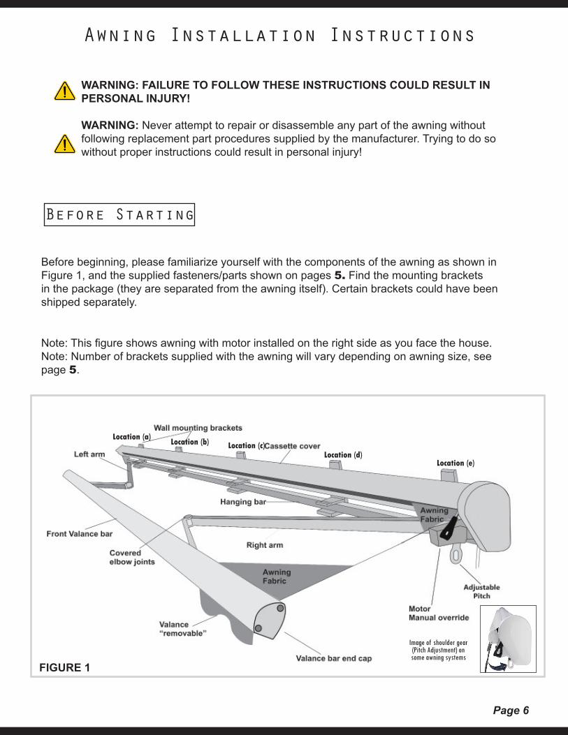
Note: This figure shows awning with motor installed on the right side as you face the house.Note: Number of brackets supplied with the awning will vary depending on awning size, see page 5.
Before beginning, please familiarize yourself with the components of the awning as shown in Figure 1, and the supplied fasteners/parts shown on pages 5. Find the mounting brackets in the package (they are separated from the awning itself). Certain brackets could have been shipped separately.
Before Starting
Awning Installation Instructions
FIGURE 1
Location (a) Location (b) Location (c)Location (d)
Location (e)
Image of shoulder gear (Pitch Adjustment) on some awning systems
Page 7
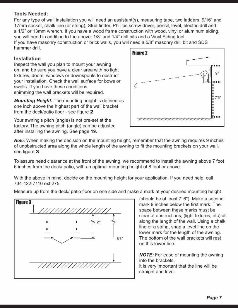
Note: When making the decision on the mounting height, remember that the awning requires 9 inches of unobstructed area along the whole length of the awning to fit the mounting brackets on your wall.see figure 3.
To assure head clearance at the front of the awning, we recommend to install the awning above 7 foot 6 inches from the deck/ patio, with an optimal mounting height of 8 foot or above.
With the above in mind, decide on the mounting height for your application. If you need help, call734-422-7110 ext.275
Measure up from the deck/ patio floor on one side and make a mark at your desired mounting height
For any type of wall installation you will need an assistant(s), measuring tape, two ladders, 9/16” and 17mm socket, chalk line (or string), Stud finder, Phillips screw-driver, pencil, level, electric drill and a 1/2” or 13mm wrench. If you have a wood frame construction with wood, vinyl or aluminum siding, you will need in addition to the above: 1/8” and 1/4” drill bits and a Vinyl Siding tool.If you have masonry construction or brick walls, you will need a 5/8” masonry drill bit and SDS hammer drill.
Figure 2
Tools Needed:
9”
InstallationInspect the wall you plan to mount your awning on, and be sure you have a clear area with no light fixtures, doors, windows or downspouts to obstruct your installation. Check the wall surface for bows or swells. If you have these conditions,shimming the wall brackets will be required.
Mounting Height: The mounting height is defined as one inch above the highest part of the wall bracket from the deck/patio floor - see figure 2.
Your awning’s pitch (angle) is not pre-set at the factory. The awning pitch (angle) can be adjusted after installing the awning. See page 19.
7’6”
Figure 3(should be at least 7’ 6"). Make a second mark 9 inches below the first mark. The space between these marks must be clear of obstructions, (light fixtures, etc) all along the length of the wall. Using a chalk line or a string, snap a level line on the lower mark for the length of the awning. The bottom of the wall brackets will reston this lower line.
NOTE: For ease of mounting the awning into the brackets,it is very important that the line will be straight and level.
9”
8’3”
Page 8
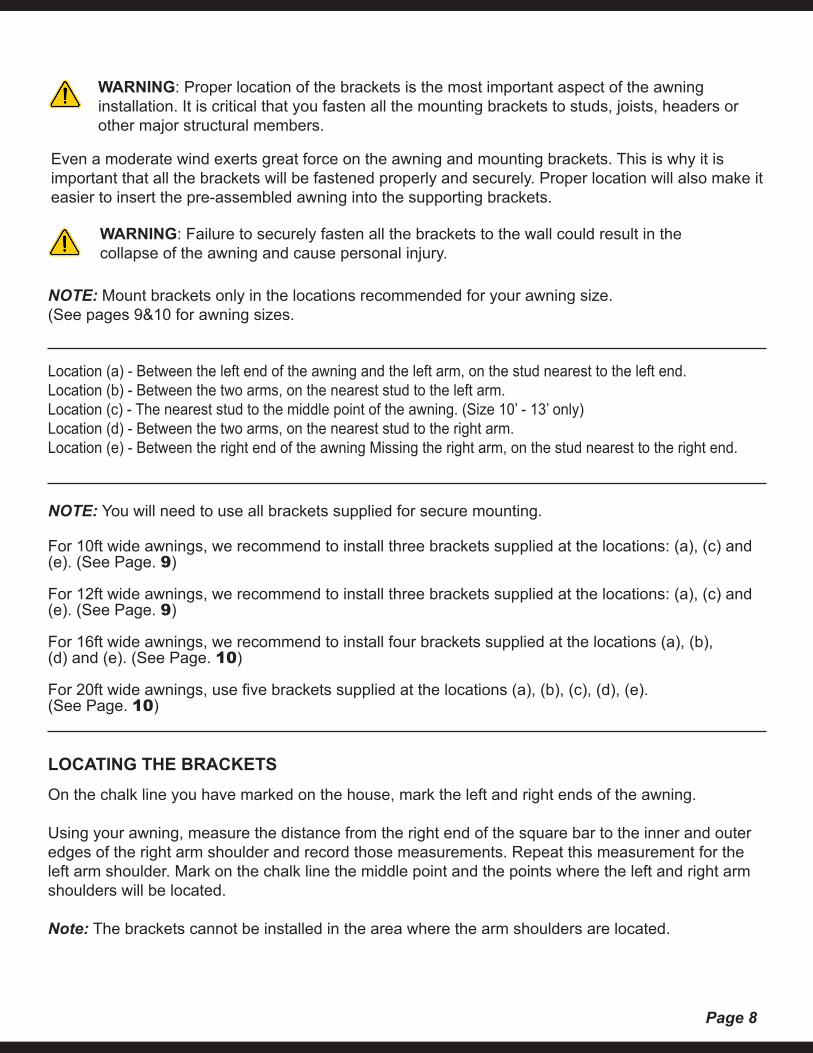
NOTE: You will need to use all brackets supplied for secure mounting.
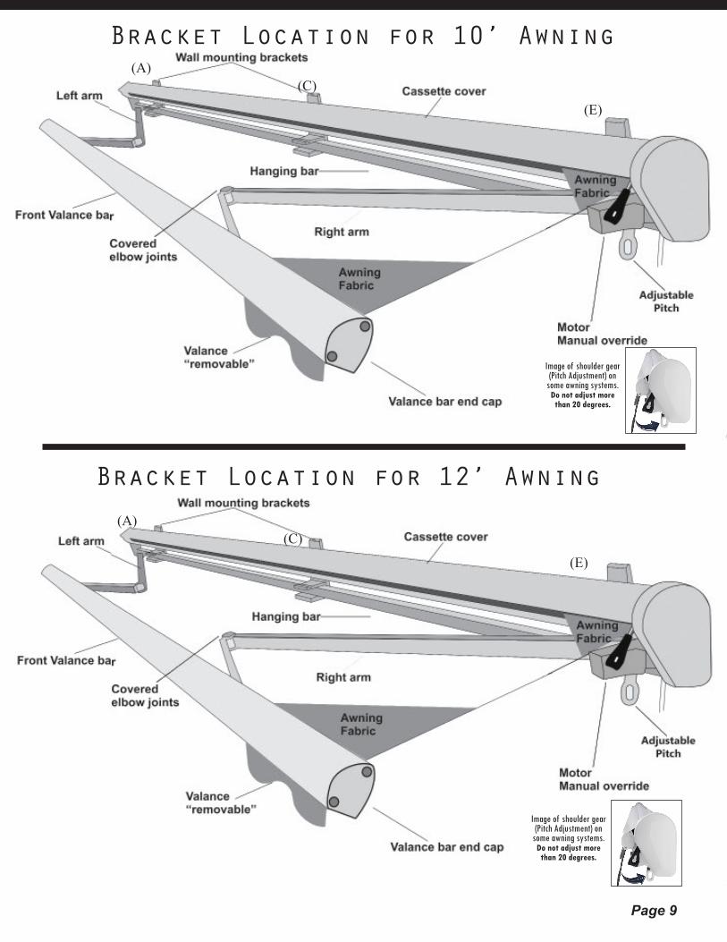
For 10ft wide awnings, we recommend to install three brackets supplied at the locations: (a), (c) and (e). (See Page. 9)
For 12ft wide awnings, we recommend to install three brackets supplied at the locations: (a), (c) and (e). (See Page. 9)
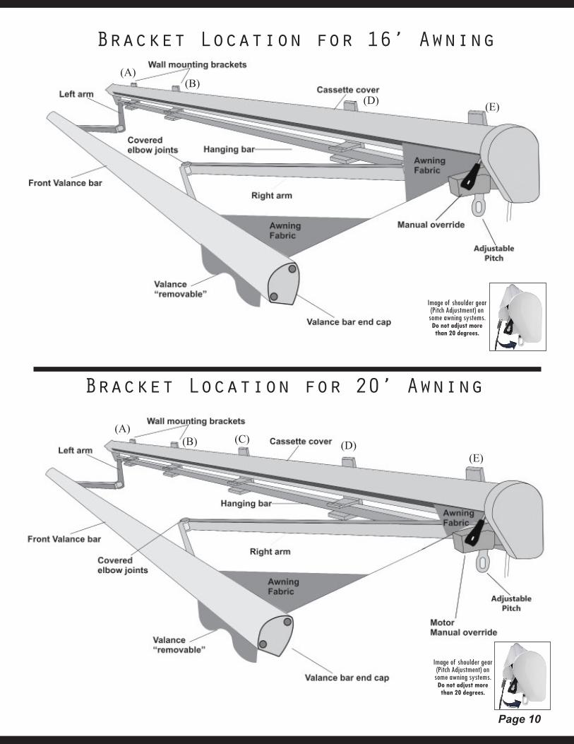
For 16ft wide awnings, we recommend to install four brackets supplied at the locations (a), (b),(d) and (e). (See Page. 10)
For 20ft wide awnings, use five brackets supplied at the locations (a), (b), (c), (d), (e).(See Page. 10)
WARNING: Proper location of the brackets is the most important aspect of the awning installation. It is critical that you fasten all the mounting brackets to studs, joists, headers or other major structural members.
Even a moderate wind exerts great force on the awning and mounting brackets. This is why it is important that all the brackets will be fastened properly and securely. Proper location will also make it easier to insert the pre-assembled awning into the supporting brackets.
WARNING: Failure to securely fasten all the brackets to the wall could result in the collapse of the awning and cause personal injury.
LOCATING THE BRACKETSOn the chalk line you have marked on the house, mark the left and right ends of the awning.
Using your awning, measure the distance from the right end of the square bar to the inner and outeredges of the right arm shoulder and record those measurements. Repeat this measurement for theleft arm shoulder. Mark on the chalk line the middle point and the points where the left and right armshoulders will be located.
Note: The brackets cannot be installed in the area where the arm shoulders are located.
Location (a) - Between the left end of the awning and the left arm, on the stud nearest to the left end.Location (b) - Between the two arms, on the nearest stud to the left arm.Location (c) - The nearest stud to the middle point of the awning. (Size 10’ - 13’ only)Location (d) - Between the two arms, on the nearest stud to the right arm.Location (e) - Between the right end of the awning Missing the right arm, on the stud nearest to the right end.
NOTE: Mount brackets only in the locations recommended for your awning size. (See pages 9&10 for awning sizes.
Page 9
(A)(C)
(E)
Bracket Location for 10’ Awning
Image of shoulder gear (Pitch Adjustment) on
some awning systems. Do not adjust more than 20 degrees.
(A)(C)
(E)
Bracket Location for 12’ Awning
Image of shoulder gear (Pitch Adjustment) on
some awning systems. Do not adjust more than 20 degrees.
Page 10
(A)(C)(B) (D)
(E)
Image of shoulder gear (Pitch Adjustment) on
some awning systems. Do not adjust more than 20 degrees.
Bracket Location for 16’ Awning(A)
(B)(D) (E)
Image of shoulder gear (Pitch Adjustment) on
some awning systems. Do not adjust more than 20 degrees.
Bracket Location for 20’ Awning
Page 11
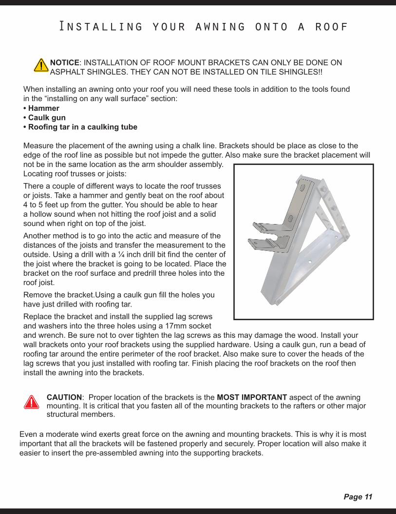
When installing an awning onto your roof you will need these tools in addition to the tools foundin the “installing on any wall surface” section:• Hammer• Caulk gun• Roofing tar in a caulking tube
Measure the placement of the awning using a chalk line. Brackets should be place as close to the edge of the roof line as possible but not impede the gutter. Also make sure the bracket placement will not be in the same location as the arm shoulder assembly.Locating roof trusses or joists:There a couple of different ways to locate the roof trusses or joists. Take a hammer and gently beat on the roof about 4 to 5 feet up from the gutter. You should be able to hear a hollow sound when not hitting the roof joist and a solid sound when right on top of the joist.Another method is to go into the actic and measure of the distances of the joists and transfer the measurement to the outside. Using a drill with a ¼ inch drill bit find the center of the joist where the bracket is going to be located. Place the bracket on the roof surface and predrill three holes into the roof joist.Remove the bracket.Using a caulk gun fill the holes you have just drilled with roofing tar.Replace the bracket and install the supplied lag screws and washers into the three holes using a 17mm socket and wrench. Be sure not to over tighten the lag screws as this may damage the wood. Install your wall brackets onto your roof brackets using the supplied hardware. Using a caulk gun, run a bead of roofing tar around the entire perimeter of the roof bracket. Also make sure to cover the heads of the lag screws that you just installed with roofing tar. Finish placing the roof brackets on the roof then install the awning into the brackets.
Installing your awning onto a roof
NOTICE: INSTALLATION OF ROOF MOUNT BRACKETS CAN ONLY BE DONE ON ASPHALT SHINGLES. THEY CAN NOT BE INSTALLED ON TILE SHINGLES!!
CAUTION: Proper location of the brackets is the MOST IMPORTANT aspect of the awning mounting. It is critical that you fasten all of the mounting brackets to the rafters or other major structural members.
Even a moderate wind exerts great force on the awning and mounting brackets. This is why it is most important that all the brackets will be fastened properly and securely. Proper location will also make it easier to insert the pre-assembled awning into the supporting brackets.
Page 12
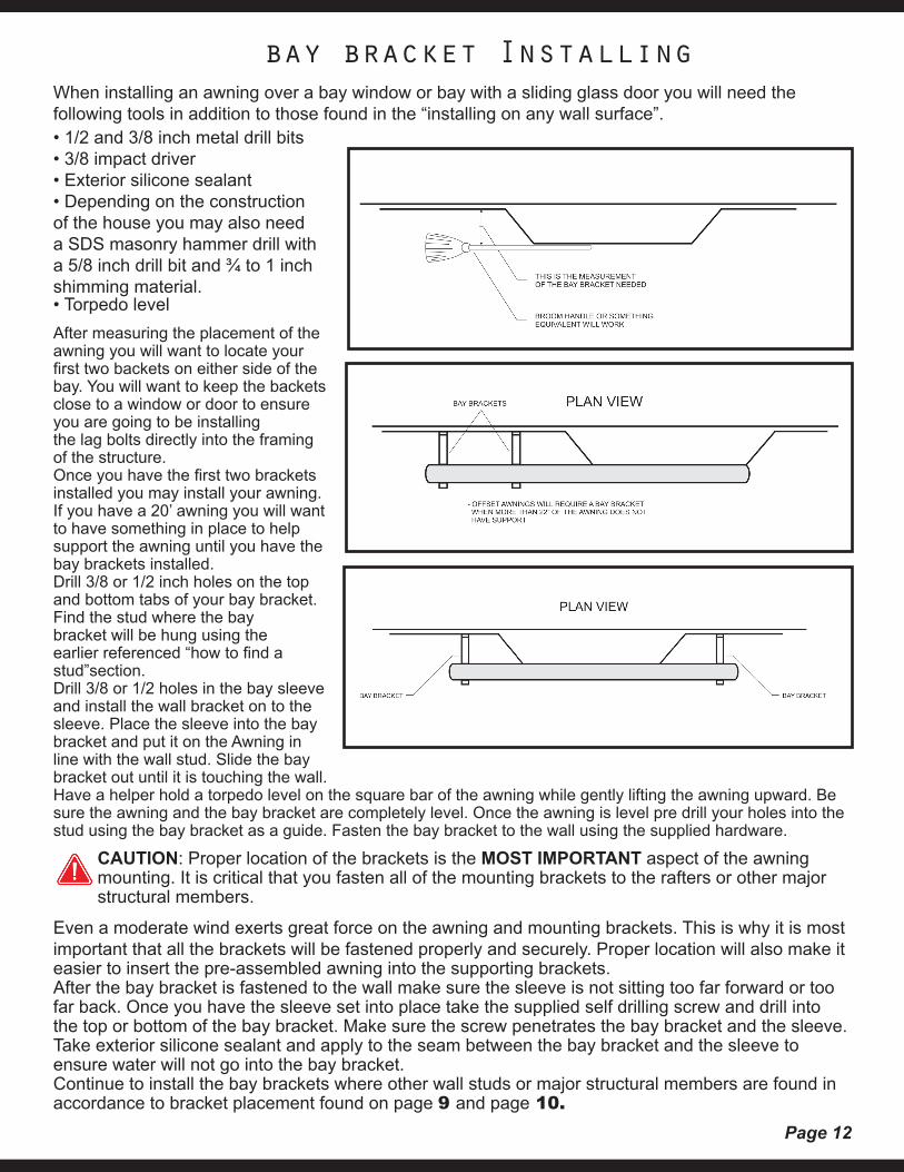
When installing an awning over a bay window or bay with a sliding glass door you will need the following tools in addition to those found in the “installing on any wall surface”.• 1/2 and 3/8 inch metal drill bits• 3/8 impact driver• Exterior silicone sealant• Depending on the construction of the house you may also need a SDS masonry hammer drill with a 5/8 inch drill bit and ¾ to 1 inch shimming material.• Torpedo levelAfter measuring the placement of the awning you will want to locate your first two backets on either side of the bay. You will want to keep the backets close to a window or door to ensure you are going to be installingthe lag bolts directly into the framing of the structure.Once you have the first two brackets installed you may install your awning. If you have a 20’ awning you will want to have something in place to help support the awning until you have the bay brackets installed.Drill 3/8 or 1/2 inch holes on the top and bottom tabs of your bay bracket.Find the stud where the bay bracket will be hung using the earlier referenced “how to find a stud”section.Drill 3/8 or 1/2 holes in the bay sleeve and install the wall bracket on to the sleeve. Place the sleeve into the bay bracket and put it on the Awning in line with the wall stud. Slide the bay bracket out until it is touching the wall.Have a helper hold a torpedo level on the square bar of the awning while gently lifting the awning upward. Be sure the awning and the bay bracket are completely level. Once the awning is level pre drill your holes into the stud using the bay bracket as a guide. Fasten the bay bracket to the wall using the supplied hardware.
bay bracket Installing
CAUTION: Proper location of the brackets is the MOST IMPORTANT aspect of the awning mounting. It is critical that you fasten all of the mounting brackets to the rafters or other major structural members.
Even a moderate wind exerts great force on the awning and mounting brackets. This is why it is most important that all the brackets will be fastened properly and securely. Proper location will also make it easier to insert the pre-assembled awning into the supporting brackets.After the bay bracket is fastened to the wall make sure the sleeve is not sitting too far forward or too far back. Once you have the sleeve set into place take the supplied self drilling screw and drill into the top or bottom of the bay bracket. Make sure the screw penetrates the bay bracket and the sleeve.Take exterior silicone sealant and apply to the seam between the bay bracket and the sleeve to ensure water will not go into the bay bracket.Continue to install the bay brackets where other wall studs or major structural members are found in accordance to bracket placement found on page 9 and page 10.
Page 13
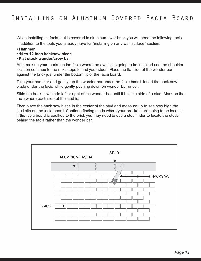
When installing on facia that is covered in aluminum over brick you will need the following tools in addition to the tools you already have for “installing on any wall surface” section.• Hammer• 10 to 12 inch hacksaw blade• Flat stock wonder/crow barAfter making your marks on the facia where the awning is going to be installed and the shoulder location continue to the next steps to find your studs. Place the flat side of the wonder bar against the brick just under the bottom lip of the facia board.
Take your hammer and gently tap the wonder bar under the facia board. Insert the hack saw blade under the facia while gently pushing down on wonder bar under.
Slide the hack saw blade left or right of the wonder bar until it hits the side of a stud. Mark on the facia where each side of the stud is.
Then place the hack saw blade in the center of the stud and measure up to see how high the stud sits on the facia board. Continue finding studs where your brackets are going to be located. If the facia board is caulked to the brick you may need to use a stud finder to locate the studs behind the facia rather than the wonder bar.
Installing on Aluminum Covered Facia Board
Page 14
Tools RequiredFor installing the awning on the soffit, under the overhang, you will need an assistant,measuring tape, two step-ladders, 9/16" socket, chalk line (orstring), Phillips screwdriver, pencil, a level, electric drill, 1/8" and 1/4" drill bits, 1/2" or 13mm wrench and a stud finder.
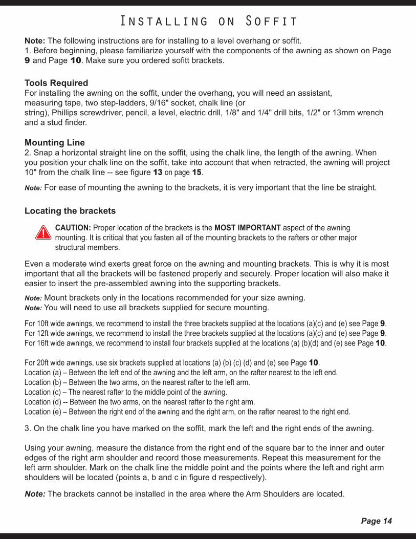
Mounting Line2. Snap a horizontal straight line on the soffit, using the chalk line, the length of the awning. When you position your chalk line on the soffit, take into account that when retracted, the awning will project 10" from the chalk line -- see figure 13 on page 15.
Note: For ease of mounting the awning to the brackets, it is very important that the line be straight.
Locating the brackets
Note: The following instructions are for installing to a level overhang or soffit.1. Before beginning, please familiarize yourself with the components of the awning as shown on Page 9 and Page 10. Make sure you ordered sofitt brackets.
Installing on Soffit
Even a moderate wind exerts great force on the awning and mounting brackets. This is why it is most important that all the brackets will be fastened properly and securely. Proper location will also make it easier to insert the pre-assembled awning into the supporting brackets.
Note: Mount brackets only in the locations recommended for your size awning.Note: You will need to use all brackets supplied for secure mounting.
For 10ft wide awnings, we recommend to install the three brackets supplied at the locations (a)(c) and (e) see Page 9.For 12ft wide awnings, we recommend to install the three brackets supplied at the locations (a)(c) and (e) see Page 9.For 16ft wide awnings, we recommend to install four brackets supplied at the locations (a) (b)(d) and (e) see Page 10.
For 20ft wide awnings, use six brackets supplied at locations (a) (b) (c) (d) and (e) see Page 10.Location (a) – Between the left end of the awning and the left arm, on the rafter nearest to the left end.Location (b) – Between the two arms, on the nearest rafter to the left arm.Location (c) – The nearest rafter to the middle point of the awning.Location (d) -- Between the two arms, on the nearest rafter to the right arm.Location (e) – Between the right end of the awning and the right arm, on the rafter nearest to the right end.
3. On the chalk line you have marked on the soffit, mark the left and the right ends of the awning.
Using your awning, measure the distance from the right end of the square bar to the inner and outer edges of the right arm shoulder and record those measurements. Repeat this measurement for the left arm shoulder. Mark on the chalk line the middle point and the points where the left and right arm shoulders will be located (points a, b and c in figure d respectively).
Note: The brackets cannot be installed in the area where the Arm Shoulders are located.
CAUTION: Proper location of the brackets is the MOST IMPORTANT aspect of the awning mounting. It is critical that you fasten all of the mounting brackets to the rafters or other major structural members.
Page 15
4. YOU MUST NOW LOCATE THE RAFTERS IN THE AREA IN WHICH EACH BRACKET MUST BE INSTALLED AS EXPLAINED EARLIER IN “LOCATING THE BRACKETS”. To find the rafters, use a stud finder. Be sure to read the stud finder instructions before usage. Mark the center of each rafter, on which a bracket will be installed with a 7” long line. 5. Position the bracket against the soffit, centered over the vertical line, with the back of the bracket even with the horizontal chalk line, and mark the two holes.
6. Drill 1/4” pilot holes about 3-1/2” into the rafter. This will prevent the framing from splitting while installing the lag screws. You may want to cut out the vinyl in the shape of the top of the bracket to ensure the bracket sits level on the rafter.
7. Using a 9/16” socket, install the bracket with the 3/8” x 4” long lag screws. Use the flat washer provided under the head of the screw. Make sure not to overtighten the lag screws; doing so may split the wood framing or weaken the screw.
8. Attach the wall brackets to the soffit brackets with the supplied hardware. Repeat for all brackets.
WARNING: Failure to securely fasten all the brackets to structural members of the soffit or failure of the structural member to support an awning could result in the collapse of the awning and cause personal injury.
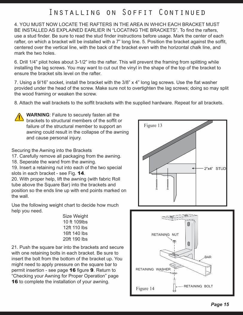
Securing the Awning into the Brackets17. Carefully remove all packaging from the awning.18. Seperate the wand from the awning.19. Insert a retaining nut into each of the two special slots in each bracket - see Fig. 14.20. With proper help, lift the awning (with fabric Roll tube above the Square Bar) into the brackets and position so the ends line up with end points marked on the wall.
Use the following weight chart to decide how much help you need.
21. Push the square bar into the brackets and secure with one retaining bolts in each bracket. Be sure to insert the bolt from the bottom of the bracket up. You might need to apply pressure on the square bar to permit insertion - see page 16 figure 9. Return to “Checking your Awning for Proper Operation” page 16 to complete the installation of your awning.
Size Weight10 ft 109lbs12ft 110 lbs16ft 140 lbs20ft 190 lbs
Installing on Soffit Continued
Figure 13
Figure 14
Page 16
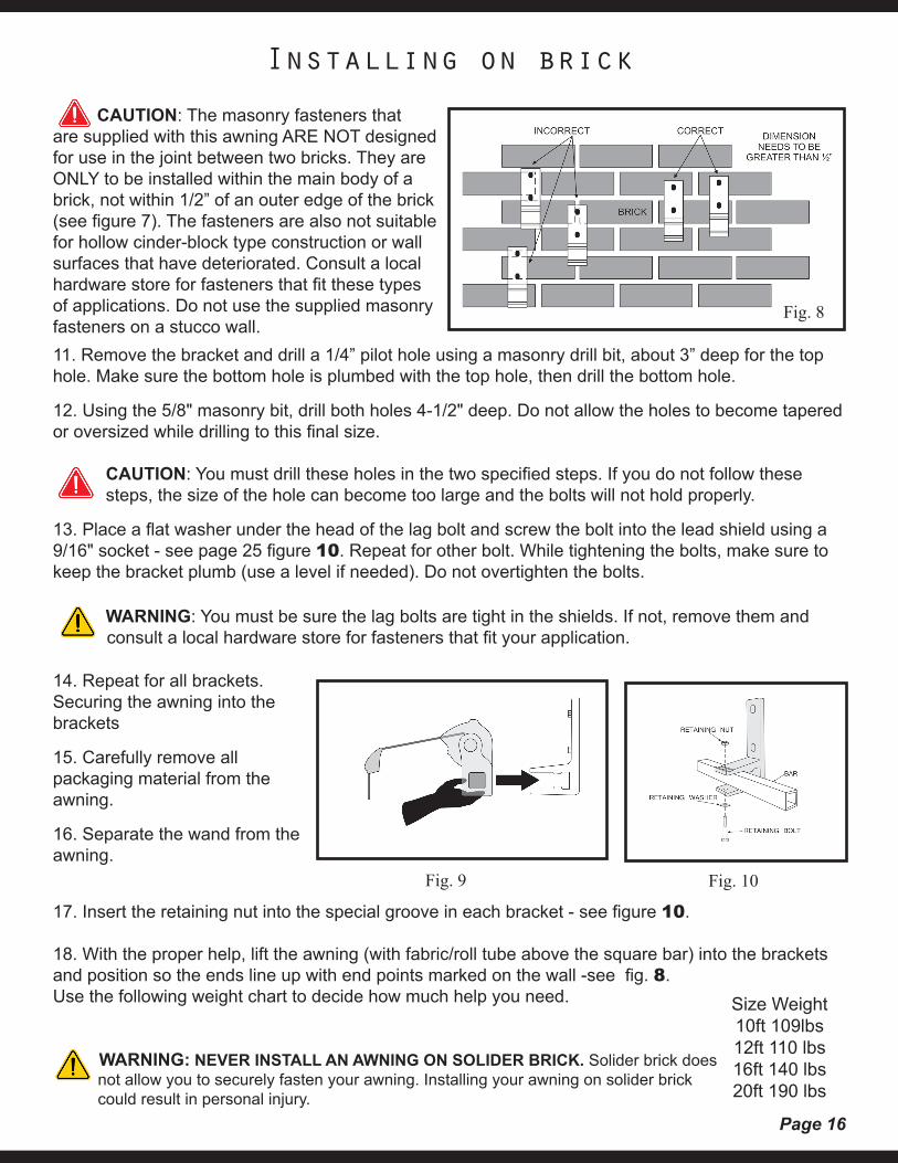
17. Insert the retaining nut into the special groove in each bracket - see figure 10.
18. With the proper help, lift the awning (with fabric/roll tube above the square bar) into the brackets and position so the ends line up with end points marked on the wall -see fig. 8.Use the following weight chart to decide how much help you need.
WARNING: NEVER INSTALL AN AWNING ON SOLIDER BRICK. Solider brick does not allow you to securely fasten your awning. Installing your awning on solider brick could result in personal injury.
11. Remove the bracket and drill a 1/4” pilot hole using a masonry drill bit, about 3” deep for the top hole. Make sure the bottom hole is plumbed with the top hole, then drill the bottom hole.
12. Using the 5/8" masonry bit, drill both holes 4-1/2" deep. Do not allow the holes to become tapered or oversized while drilling to this final size.
CAUTION: You must drill these holes in the two specified steps. If you do not follow these steps, the size of the hole can become too large and the bolts will not hold properly.
13. Place a flat washer under the head of the lag bolt and screw the bolt into the lead shield using a 9/16" socket - see page 25 figure 10. Repeat for other bolt. While tightening the bolts, make sure to keep the bracket plumb (use a level if needed). Do not overtighten the bolts.
WARNING: You must be sure the lag bolts are tight in the shields. If not, remove them and consult a local hardware store for fasteners that fit your application.
14. Repeat for all brackets.Securing the awning into the brackets
15. Carefully remove all packaging material from the awning.
16. Separate the wand from the awning.
Size Weight10ft 109lbs12ft 110 lbs16ft 140 lbs20ft 190 lbs
CAUTION: The masonry fasteners that are supplied with this awning ARE NOT designed for use in the joint between two bricks. They are ONLY to be installed within the main body of a brick, not within 1/2” of an outer edge of the brick (see figure 7). The fasteners are also not suitable for hollow cinder-block type construction or wall surfaces that have deteriorated. Consult a local hardware store for fasteners that fit these types of applications. Do not use the supplied masonry fasteners on a stucco wall.
Installing on brick
Fig. 9 Fig. 10
Fig. 8
Page 17
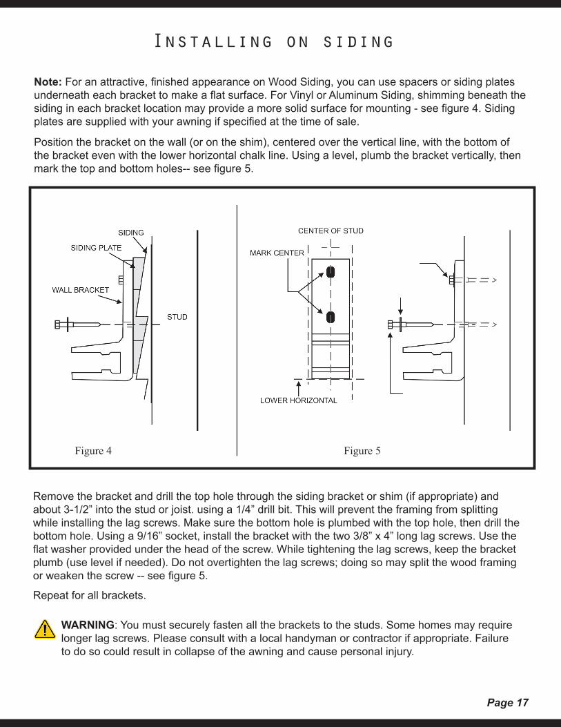
Note: For an attractive, finished appearance on Wood Siding, you can use spacers or siding plates underneath each bracket to make a flat surface. For Vinyl or Aluminum Siding, shimming beneath the siding in each bracket location may provide a more solid surface for mounting - see figure 4. Sidingplates are supplied with your awning if specified at the time of sale.
Position the bracket on the wall (or on the shim), centered over the vertical line, with the bottom of the bracket even with the lower horizontal chalk line. Using a level, plumb the bracket vertically, then mark the top and bottom holes-- see figure 5.
Remove the bracket and drill the top hole through the siding bracket or shim (if appropriate) and about 3-1/2” into the stud or joist. using a 1/4” drill bit. This will prevent the framing from splitting while installing the lag screws. Make sure the bottom hole is plumbed with the top hole, then drill the bottom hole. Using a 9/16” socket, install the bracket with the two 3/8” x 4” long lag screws. Use the flat washer provided under the head of the screw. While tightening the lag screws, keep the bracket plumb (use level if needed). Do not overtighten the lag screws; doing so may split the wood framing or weaken the screw -- see figure 5.
Repeat for all brackets.
Installing on siding
WARNING: You must securely fasten all the brackets to the studs. Some homes may require longer lag screws. Please consult with a local handyman or contractor if appropriate. Failure to do so could result in collapse of the awning and cause personal injury.
Figure 4 Figure 5
Page 18
Stop
Out
In
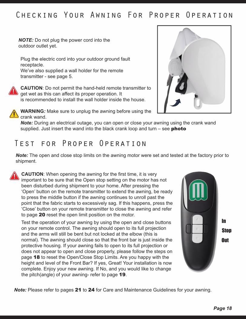
Plug the electric cord into your outdoor ground fault receptacle.We’ve also supplied a wall holder for the remote transmitter - see page 5.
CAUTION: Do not permit the hand-held remote transmitter to get wet as this can affect its proper operation. It is recommended to install the wall holder inside the house.
WARNING: Make sure to unplug the awning before using the crank wand.Note: During an electrical outage, you can open or close your awning using the crank wand supplied. Just insert the wand into the black crank loop and turn – see photo
Note: The open and close stop limits on the awning motor were set and tested at the factory prior to shipment.
CAUTION: When opening the awning for the first time, it is very important to be sure that the Open stop setting on the motor has not been disturbed during shipment to your home. After pressing the ‘Open’ button on the remote transmitter to extend the awning, be ready to press the middle button if the awning continues to unroll past the point that the fabric starts to excessively sag. If this happens, press the ‘Close’ button on your remote transmitter to close the awning and refer to page 20 reset the open limit position on the motor. Test the operation of your awning by using the open and close buttons on your remote control. The awning should open to its full projection and the arms will still be bent but not locked at the elbow (this is normal). The awning should close so that the front bar is just inside the protective housing. If your awning fails to open to its full projection or does not appear to open and close properly, please follow the steps on page 18 to reset the Open/Close Stop Limits. Are you happy with the height and level of the Front Bar? If yes, Great! Your installation is now complete. Enjoy your new awning. If No, and you would like to change the pitch(angle) of your awning- refer to page 19.
NOTE: Do not plug the power cord into the outdoor outlet yet.
Checking Your Awning For Proper Operation
Test for Proper Operation
Note: Please refer to pages 21 to 24 for Care and Maintenance Guidelines for your awning.
Page 19
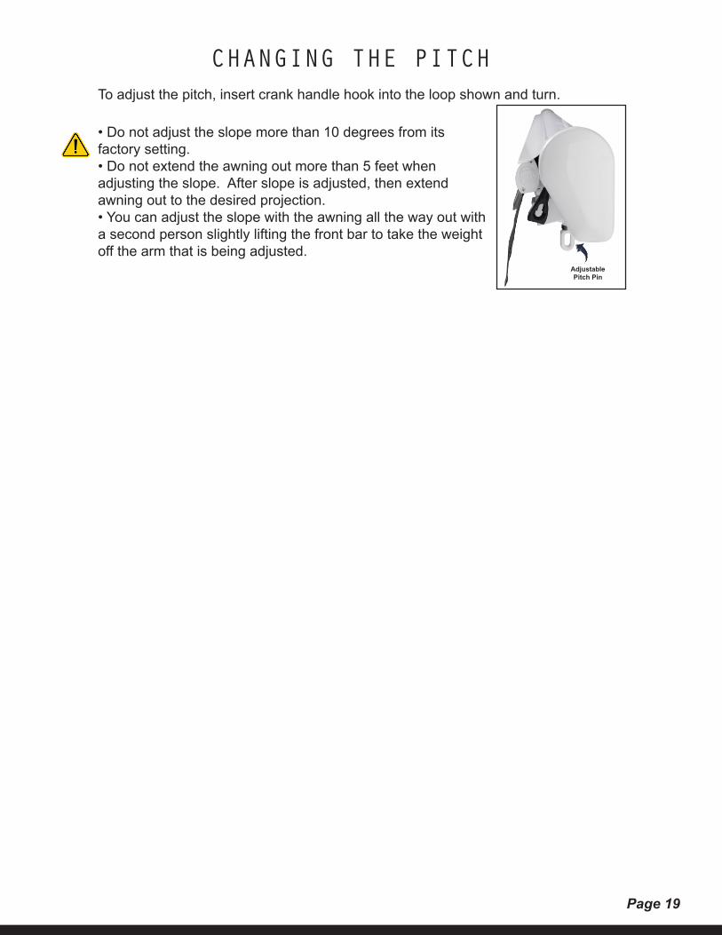
CHANGING THE PITCHTo adjust the pitch, insert crank handle hook into the loop shown and turn.
• Do not adjust the slope more than 10 degrees from its factory setting.• Do not extend the awning out more than 5 feet when adjusting the slope. After slope is adjusted, then extend awning out to the desired projection.• You can adjust the slope with the awning all the way out with a second person slightly lifting the front bar to take the weight off the arm that is being adjusted.
Adjustable Pitch Pin
Page 20
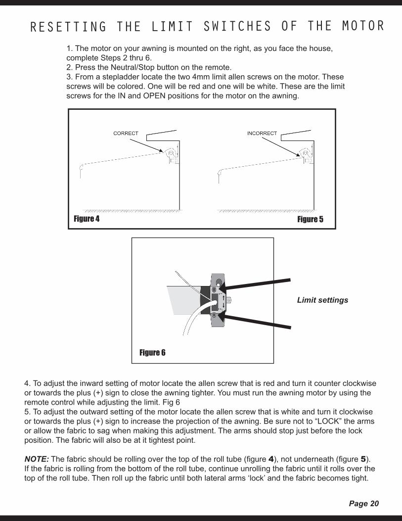
1. The motor on your awning is mounted on the right, as you face the house, complete Steps 2 thru 6.2. Press the Neutral/Stop button on the remote.3. From a stepladder locate the two 4mm limit allen screws on the motor. These screws will be colored. One will be red and one will be white. These are the limit screws for the IN and OPEN positions for the motor on the awning.
4. To adjust the inward setting of motor locate the allen screw that is red and turn it counter clockwise or towards the plus (+) sign to close the awning tighter. You must run the awning motor by using the remote control while adjusting the limit. Fig 65. To adjust the outward setting of the motor locate the allen screw that is white and turn it clockwise or towards the plus (+) sign to increase the projection of the awning. Be sure not to “LOCK” the arms or allow the fabric to sag when making this adjustment. The arms should stop just before the lock position. The fabric will also be at it tightest point.
NOTE: The fabric should be rolling over the top of the roll tube (figure 4), not underneath (figure 5). If the fabric is rolling from the bottom of the roll tube, continue unrolling the fabric until it rolls over the top of the roll tube. Then roll up the fabric until both lateral arms ‘lock’ and the fabric becomes tight.
RESETTING THE LIMIT SWITCHES OF THE MOTOR
Figure 4 Figure 5
Figure 6
Limit settings
Page 21
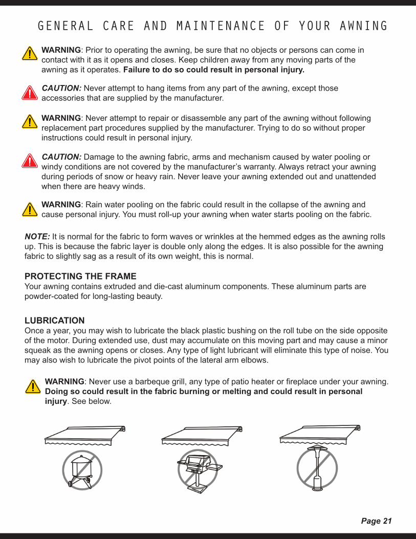
WARNING: Prior to operating the awning, be sure that no objects or persons can come in contact with it as it opens and closes. Keep children away from any moving parts of the awning as it operates. Failure to do so could result in personal injury.
GENERAL CARE AND MAINTENANCE OF YOUR AWNING
CAUTION: Never attempt to hang items from any part of the awning, except those accessories that are supplied by the manufacturer.
WARNING: Never attempt to repair or disassemble any part of the awning without following replacement part procedures supplied by the manufacturer. Trying to do so without proper instructions could result in personal injury.
CAUTION: Damage to the awning fabric, arms and mechanism caused by water pooling or windy conditions are not covered by the manufacturer’s warranty. Always retract your awning during periods of snow or heavy rain. Never leave your awning extended out and unattended when there are heavy winds.
WARNING: Rain water pooling on the fabric could result in the collapse of the awning and cause personal injury. You must roll-up your awning when water starts pooling on the fabric.
NOTE: It is normal for the fabric to form waves or wrinkles at the hemmed edges as the awning rolls up. This is because the fabric layer is double only along the edges. It is also possible for the awning fabric to slightly sag as a result of its own weight, this is normal.
PROTECTING THE FRAMEYour awning contains extruded and die-cast aluminum components. These aluminum parts are powder-coated for long-lasting beauty.
LUBRICATIONOnce a year, you may wish to lubricate the black plastic bushing on the roll tube on the side opposite of the motor. During extended use, dust may accumulate on this moving part and may cause a minor squeak as the awning opens or closes. Any type of light lubricant will eliminate this type of noise. You may also wish to lubricate the pivot points of the lateral arm elbows.
WARNING: Never use a barbeque grill, any type of patio heater or fireplace under your awning. Doing so could result in the fabric burning or melting and could result in personal injury. See below.
Page 22
The motor is supplied by Dooya Inc., the recognized world leader in specialized electric tubular motors for awnings and sunshades. This 110-volt motor is UL (Underwriters Laboratories) and CSA (Canadian Standards Association) approved. This motor features the manual override option that allows you the safety and convenience of manual operation during electrical failures.
The electric motor is equipped with an automatic overheat protection shutoff system. If you run your awning several times continuously, the motor will stop its operation. It will resume normal operation after 15 minutes of cooling down.
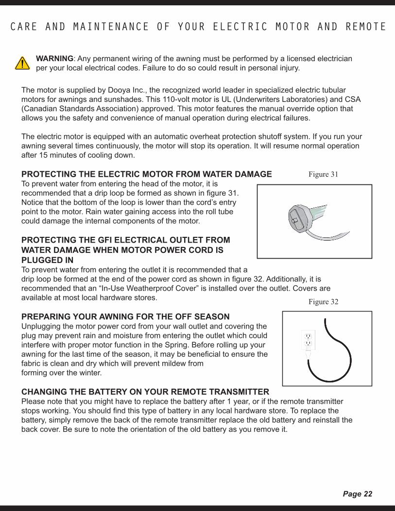
PROTECTING THE ELECTRIC MOTOR FROM WATER DAMAGETo prevent water from entering the head of the motor, it is recommended that a drip loop be formed as shown in figure 31. Notice that the bottom of the loop is lower than the cord’s entry point to the motor. Rain water gaining access into the roll tube could damage the internal components of the motor.
PROTECTING THE GFI ELECTRICAL OUTLET FROM WATER DAMAGE WHEN MOTOR POWER CORD IS PLUGGED INTo prevent water from entering the outlet it is recommended that a drip loop be formed at the end of the power cord as shown in figure 32. Additionally, it is recommended that an “In-Use Weatherproof Cover” is installed over the outlet. Covers are available at most local hardware stores.
PREPARING YOUR AWNING FOR THE OFF SEASONUnplugging the motor power cord from your wall outlet and covering the plug may prevent rain and moisture from entering the outlet which could interfere with proper motor function in the Spring. Before rolling up your awning for the last time of the season, it may be beneficial to ensure the fabric is clean and dry which will prevent mildew from forming over the winter.
CHANGING THE BATTERY ON YOUR REMOTE TRANSMITTERPlease note that you might have to replace the battery after 1 year, or if the remote transmitter stops working. You should find this type of battery in any local hardware store. To replace the battery, simply remove the back of the remote transmitter replace the old battery and reinstall the back cover. Be sure to note the orientation of the old battery as you remove it.
CARE AND MAINTENANCE OF YOUR ELECTRIC MOTOR AND REMOTE
WARNING: Any permanent wiring of the awning must be performed by a licensed electrician per your local electrical codes. Failure to do so could result in personal injury.
Figure 32
Figure 31
Page 23
Care and Maintenance - Woven Acrylic Fabrics
The woven acrylic fabrics are made of 100% solution-dyed, 100% recyclable fiber and have a special finishwhich delays the formation and accumulation of dirt. To preserve this finish, cleaning of the fabric must include the following.
Standard MaintenanceThoroughly remove the dust from the dry awning fabric by vacuum cleaning, gently beating or brushing. Then clean with a prolonged spraying of luke warm water and a mild soap while gently brushing. Rinse thoroughly to remove soap.
Stain RemovalFor more stubborn cases, a general solution of no more than a ½ cup (4oz.) of chlorine bleach and a ¼ cup (2oz) of mild soap per gallon of water is normally recommended. Do not leave this mixture on the fabric more than 20 minutes. Then the fabric should be rinsed thoroughly with cold water to remove all of the mixture.
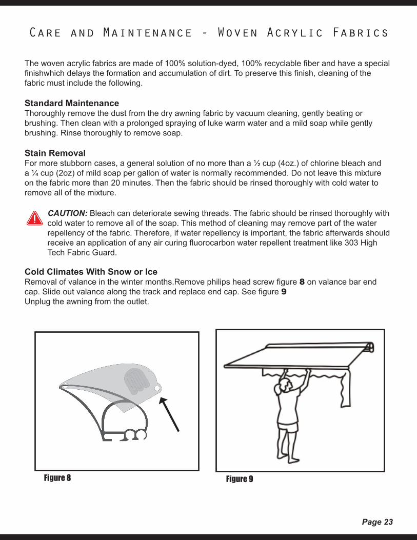
Cold Climates With Snow or IceRemoval of valance in the winter months.Remove philips head screw figure 8 on valance bar end cap. Slide out valance along the track and replace end cap. See figure 9Unplug the awning from the outlet.
Figure 9Figure 8
CAUTION: Bleach can deteriorate sewing threads. The fabric should be rinsed thoroughly with cold water to remove all of the soap. This method of cleaning may remove part of the water repellency of the fabric. Therefore, if water repellency is important, the fabric afterwards should receive an application of any air curing fluorocarbon water repellent treatment like 303 High Tech Fabric Guard.
Page 24
1. Use manual crank handle, and put into white hook.
2. Slowly turn to lower only one end of the awning to allow water to drain off
3. If all the water has still not drained off of the awning then move to the other side and slowly raise it.
HOW TO DRAIN RAIN WATER FROM THE AWNING FABRIC
WARNING: The awning is not designed to hold the weight of rainwater pooling on the fabric. Accumulation of rainwater on the fabric could collapse the awning and cause serious injury.
If, for any reason, rainwater accumulated on the fabric, follow the instructions below to remove thewater.
WARNING: Never walk under an awning with water accumulated on the fabric! There could be a tremendous amount of weight on the awning and the frame could collapse at any moment and cause serious injury!
Page 25
Can I “hard-wire” the awning motor into my home -Marygrove cannot be responsible for any changes in electrical configurtion of the motorized awning. Have your electrician contact a Marygrove Awning representative for information regarding the motor.
How low can the pitch be set - As low as a 35 degree angle.
Fabric wrinkles when the awning is opened/closed -The awning fabric has a hem along both ends of the material; some wrinkling is a characteristic of the extra thickness along either edge. This wrinkling may be more noticeable when retracted and after prolonged periods when the awning is not used. This condition is normal. Leaving the awning open in warm weather should minimize the wrinkling over a period of time. Ensuring that the awning fabric is centered on both the Roller tube and the Front Bar may also lessen the appearance of wrinkles in the fabric.
Lateral arms (elbows) are not even when awning is retracted -Each lateral arm is supported individually to the square bar. Therefore, it is normal that when the awning is closed, the arms may not necessarily be even with each other when viewed from the front or underside of the awning. Insure that fabric is evenly centered on Roller tube and Front Bar. This will assist the lateral arm in closing more evenly.
The roller tube and fabric appear to bounce when opening and closing the awning. -The roller tube that holds the fabric is supported only at the extreme ends and it bows toward the center. As the Roller tube rotates, it may move up and down toward the center. This is a natural tendency of the bar and may be more noticeable with larger size awnings.
Fabric is not centered on the roller tube or the front bar. Fabric gathers more to one side on the roller tube as the awning retracts.1. Press the Neutral/Middle button on the remote.2. Unplug the power cord from the electrical outlet on the wall.3. Manually crank the awning open; continue unrolling the fabric until the steel roller tube is fully exposed.4. Center the fabric on both roller tube and front bar.5. Manually roll up the fabric until both lateral arms ‘lock’ and the fabric becomes tight; ensure that the fabric is rolling over the top of the roller tube.
Fabric seams leaking rain water -Although the fabric was treated to be water-repellent, rain water may leak through the needle holes created when we stitch the fabric panels together. To minimize this leak, apply a sealer like 303 High Tech Fabric Guard to the seams from the underside of the awning. Allow it to dry for several hours before closing your awning. For more information. please see www.303products.com
TROUBLESHOOTING
Page 26
After installing, the awning will not function -Is there power to the receptacle? Verify that the red light is on the remote transmitter comes on when you press and hold a button If red light does not come on, remove battery and reinsert in slot and try pushing button again.
The red light on the remote transmitter does not come on when I press and hold the button -If no light, remove the battery and reinsert in slot and try pushing button again, if no light replace battery.
Awning rolls out but will not retract - Reset the IN/OUT limit settings using the instructions in the installation manual – see Page 20
Awning retracts but will not roll out -Reset the IN/OUT limit settings using the instructions in the installation manual – see Page 20
Awning rolls out and keeps going and fabric starts to sag -Reset the IN/OUT limit settings using the instructions in the installation manual – see Page 20
When opening or closing my awning, the awning does not stop at the correct OPEN/CLOSE position and I must use the Neutral (STOP) button on the remote transmitter. -Reset the IN/OUT limit settings using the instructions in the installation manual - see Page 20.
Awning will not open or retract using the Manual Override Crank -The remote must be in the NEUTRAL position in order for the manual override to operate correctly when using the crank. Please make sure to ALWAYS unplug the cord from the electrical receptacle.
Remote transmitter, can I use more than one -No. Unfortunately the motor only allows for one remote control To be programmed to it at one time.
After opening and closing the awning several times, the motor suddenly stopped working and will not close or open the rest of the way -The overtemperature sensor has temporarily shut off the motor. The motor will resume normal operation after about 45 minutes of cooling down. Note: If the awning is in the closed position and ambient temperature is elevated, it might take a little longer.
When operating my awning the GFI on the outlet keeps tripping and interrupting the power supply to the awning - First test the GFI by plugging in another appliance (such as a hairdryer) to insure outlet is working properly, if OK. Test awning by getting power from other outlet inside the house using an extension cord, if OK.There may be moisture in the motor housing causing the GFI to trip, please allow motor to dry over 2-3 sunny days. Motor is designed to operate if it gets wet and dries out.
TROUBLESHOOTING - CONTINUED

Page 27
WHO IS ENTITLED TO THIS WARRANTY?This Warranty applies only to the original purchaser who paid for the product and may not be assigned or transferred to subsequent owners. This Warranty applies only to NEW products purchased and installed in the US by an authorized Marygrove Dealer.
WHAT ARE THE RESPONSIBILITIES OF MARYGROVE AWNINGS UNDER THIS WARRANTY?Subject to the terms and conditions set forth herein, Marygrove Awnings will furnish replacements for parts found by them to be defective in design, manufacture or assembly, under each specific component or product warranty as set forth below.
WHO CAN MAKE CLAIMS UNDER THIS WARRANTY?1. Before any claims may be made under this Warranty, the original purchaser must provide prove of purchase from an authorized dealer of Marygrove Awnings. This Warranty coverage is for new awning purchases only and does not cover used or demo units. The purchaser agrees and acknowledges that this Warranty agreement constitutes an executor contract.2. The purchaser must use care in maintenance, operation, use, and storage of the product in accordance with the instructions contained in the owner’s manual. ANY FAILURE TO HAVE AN AUTHORIZED DEALER INSTALL OR OWNER TO MAINTAIN, OPERATE, USE AND STORE THE PRODUCT IN ACCORDANCE WITH THE INSTRUCTIONS CONTAINED IN THE OWNER’S MANUAL WILL NULLIFY THIS WARRANTY AND RELIEVE MARYGROVE AWNINGS FROM ANY RESPONSIBILITY OR LIABILITY UNDER THIS WARRANTY.3. Promptly notify installing dealer who will notify Marygrove Awnings of any claims.4. The purchaser/dealer may be required to provide a photograph of any defective parts. The purchaser may also be required to pay a deposit until the defective parts are returned to Marygrove Awnings for inspection. The purchaser/dealer must obtain a return authorization from Marygrove Awnings customer service department prior to the return of any part and after having received such authorization, return the part or product, freight prepaid, to Marygrove Awnings.
WHAT IS COVERED UNDER THIS WARRANTY?1. The following components of the Marygrove Awning are covered under this Warranty, subject to the limitations set forth below. These components have a five (5) year limited warranty, against manufacturer’s defects as outlined below:(a) Should the purchaser promptly notify Marygrove Awnings of such defects within five years (60 months) from the date of the original purchase and it is determined after inspection that there is indeed a defective component it will then be replaced at no charge.
2. COVERED COMPONENTS:STRUCTURAL SUPPORTS, which include the lateral arms, the square bar, the front bar and all other attached supports are warranted not to fail for five (5) years provided that the components are not subjected to excessive winds or water pooling on the fabric.ROLLER BAR is warranted for five (5) years against any and all damage including cracking and permanent bowing that would affect the performance of the awning, provided that the awning is not subjected to excessive winds or water pooling on the fabric.STANDARD FABRIC is warranted for five (5) years against:(a) Excessive fading under normal conditions if maintained, operated, used, and stored in accordance with the instructions contained in the owner’s manual.(b) Mildew on the fabric. Mildew will not form on the fabric itself, but may form on dirt and dust that
Warranty
Page 28
have not been removed from it. Please see maintenance instructions for proper cleaning-outlined in owner’s manual.(c) Excessive cracking or peeling under normal conditions if maintained, operated, used, and stored in accordance with the instructions contained in the owner’s manual, and provided that the awning is not subjected to excessive winds or water pooling on the fabric.SUNBRELLA™ FABRIC: See separate Sunbrella warranty. Marygrove Awnings will honor their warranty based on purchase date and it will only cover fabric cost as outlined and does not include delivery or installation.ELECTRIC MOTOR is warranted for five (5) years not to fail under normal conditions if maintained, operated, used, and stored in accordance with the instructions contained in the owner’s manual.
AWNING ACCESSORIES (defined as accessories attached to the awning) are warranted for (12) months not to fail under normal conditions if maintained, operated, used, and stored in accordance with the instructions contained in the owner’s manual.
WHAT IS NOT COVERED UNDER THIS WARRANTY?1. Marygrove Awnings are not designed to be used for carports and are not designed to be installed on moving vehicles. Any damage that results from the Purchaser’s use of Marygrove Awnings for carports or on moving vehicles is not covered by this warranty.2. Any failure or damage of the components that results from any intentional or negligent actions by the purchaser or by any other person is not covered by this Warranty.3. It is the responsibility of the purchaser or authorized dealer to securely fasten the awning to studs, joists, headers or other structural members. Any failure or damage that results from the awning falling from its installed position is not covered by this Warranty.4. Labor charges connected with installation of replacement parts are not covered by this Warranty.5. Freight expenses to and from Marygrove Awnings in shipping damaged or replacement parts are not covered by this Warranty and must be paid by the purchaser.6. Stretching of fabric or damage to any structural component caused by wind or water pooling on the fabric or any other weather are not covered by this Warranty.7. Tears or rips caused by failure to protect the product from sharp objects are not covered by this Warranty.8. Wind damage due to leaving awning rolled out during foul weather is not covered under this Warranty.9. Fabric discoloration or failure due to chemical exposure (includes tree sap, bird droppings, leaves, insect/Bee sprays and or debris.) are not covered under this Warranty.10. Mildew caused by dirt resting on the product, or the product being rolled up while wet is not covered by this Warranty.11. Damage caused by acts of God.12. Any modification or addition to the awning structure and support system or to the electric motor or its wiring will nullify this Warranty and relieve MarygroveWholesale.com from any responsibility or liability under this Warranty.
GENERAL PROVISIONS AND LIMITATIONS1. THE WARRANTY GRANTED HEREIN IS THE EXCLUSIVE REMEDY FOR THE ORIGINAL PURCHASER. MARYGROVE AWNINGS MAKES NO OTHER WARRANTIES TO THE PURCHASER, EXPRESS, STATUTORY, IMPLIED OR OTHERWISE AND ALL IMPLIED WARRANTIES, INCLUDING WITHOUT LIMITATIONS, IMPLIED WARRANTIES OF MERCHANTABILITY AND FITNESS FOR A PARTICULAR PURPOSE, ARE HEREBY DISCLAIMED.
Warranty
Page 29
2. TO THE EXTENT PERMITTED BY LAW, MARYGROVE AWNINGS SHALL HAVE NO LIABILITY TO THE PURCHASER OR ANY OTHER PERSON FOR INCIDENTAL, SPECIAL, CONSEQUENTIAL, INDIRECT OR SIMILAR DAMAGES OF ANY KIND OR NATURE WHATSOEVER, WHETHER ARISING OUT OF BREACH OF WARRANTY OR OTHER BREACH OF CONTRACT, NEGLIGENCE OR OTHER TORT, OR OTHERWISE, EVEN IF MarygroveWholesale.COM SHALL HAVE BEEN ADVISED OF THE POSSIBILITY OR LIKELIHOOD OF SUCH POTENTIAL LOSS OR DAMAGE. IN NO EVENT SHALL MARYGROVE AWNINGS BE LIABLE FOR LOSS OF PROFITS AND/OR WAGES.3. SOME STATES DO NOT ALLOW LIMITATIONS ON HOW LONG AN IMPLIED WARRANTY LASTS, OR DO NOT ALLOW THE EXCLUSION OR LIMITATION OF INCIDENTAL OR CONSEQUENTIAL DAMAGES, SO THE ABOVE LIMITATIONS MAY NOT APPLY TO YOU.4. THIS WARRANTY GIVES YOU SPECIFIC RIGHTS, AND YOU MAY HAVE OTHER RIGHTS, WHICH VARY FROM STATE TO STATE.
Warranty is provided by:Marygrove Awnings, 12700 Merriman Rd, Livonia MI 48150
1-800-44-Awning
Warranty
Page 30
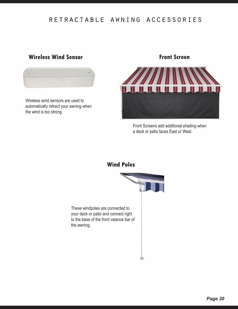
retractable awning accessories
Wind Poles
Wireless Wind Sensor Front Screen
Front Screens add additional shading when a deck or patio faces East or West.
These windpoles are connected to your deck or patio and connect right to the base of the front valance bar of the awning.
Wireless wind sensors are used to automatically retract your awning when the wind is too strong.
Page 31
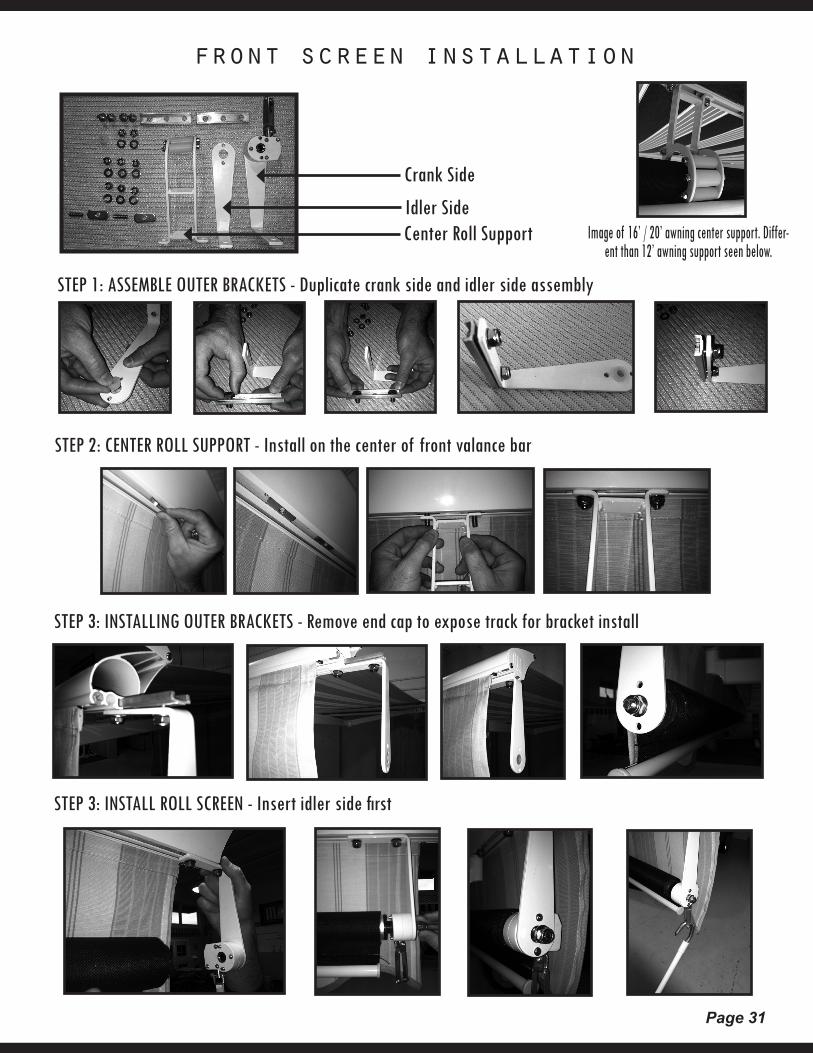
front screen installation
STEP 1: ASSEMBLE OUTER BRACKETS - Duplicate crank side and idler side assembly
Crank Side
Idler SideCenter Roll Support
STEP 2: CENTER ROLL SUPPORT - Install on the center of front valance bar
STEP 3: INSTALLING OUTER BRACKETS - Remove end cap to expose track for bracket install
STEP 3: INSTALL ROLL SCREEN - Insert idler side first
Image of 16’ / 20’ awning center support. Differ-ent than 12’ awning support seen below.
Page 32
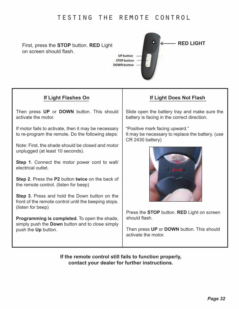
testing the remote control
RED LIGHTFirst, press the STOP button. RED Light on screen should flash.
If Light Flashes On
Then press UP or DOWN button. This should activate the motor.
If motor fails to activate, then it may be necessary to re-program the remote. Do the following steps:
Note: First, the shade should be closed and motor unplugged (at least 10 seconds).
Step 1. Connect the motor power cord to wall/electrical outlet.
Step 2. Press the P2 button twice on the back of the remote control. (listen for beep)
Step 3. Press and hold the Down button on the front of the remote control until the beeping stops. (listen for beep)
Programming is completed. To open the shade, simply push the Down button and to close simply push the Up button.
If Light Does Not Flash
Slide open the battery tray and make sure the battery is facing in the correct direction.
“Positive mark facing upward.”It may be necessary to replace the battery. (use CR 2430 battery)
Press the STOP button. RED Light on screen should flash.
Then press UP or DOWN button. This should activate the motor.
If the remote control still fails to function properly, contact your dealer for further instructions.
Page 33
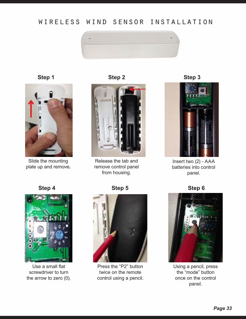
wireless wind sensor installation
Step 1 Step 2 Step 3
Step 4 Step 5 Step 6
Slide the mounting plate up and remove.
Release the tab and remove control panel
from housing.
Insert two (2) - AAA batteries into control
panel.
Use a small flat screwdriver to turn
the arrow to zero (0).
Press the “P2” button twice on the remote
control using a pencil.
Using a pencil, press the “mode” button
once on the control panel.
Page 34
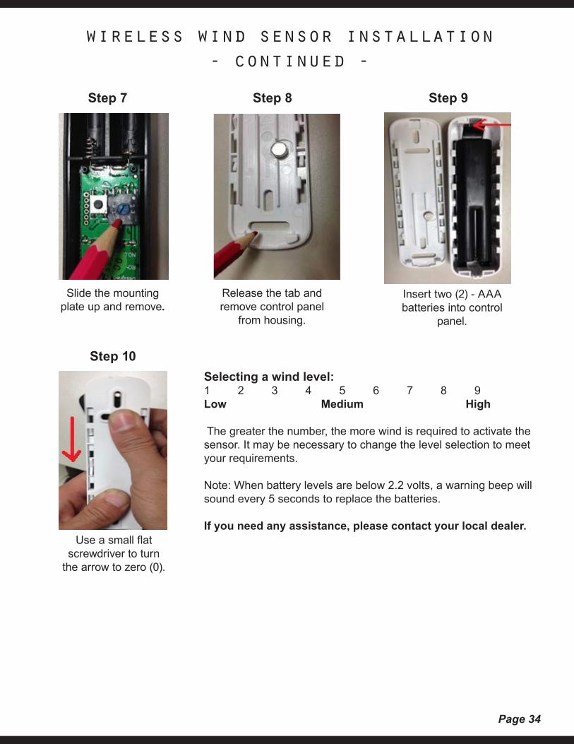
wireless wind sensor installation - continued -
Step 7 Step 8 Step 9
Step 10
Slide the mounting plate up and remove.
Release the tab and remove control panel
from housing.
Insert two (2) - AAA batteries into control
panel.
Use a small flat screwdriver to turn
the arrow to zero (0).
Selecting a wind level:1 2 3 4 5 6 7 8 9Low Medium High The greater the number, the more wind is required to activate the sensor. It may be necessary to change the level selection to meet your requirements.
Note: When battery levels are below 2.2 volts, a warning beep will sound every 5 seconds to replace the batteries.
If you need any assistance, please contact your local dealer.
Page 35
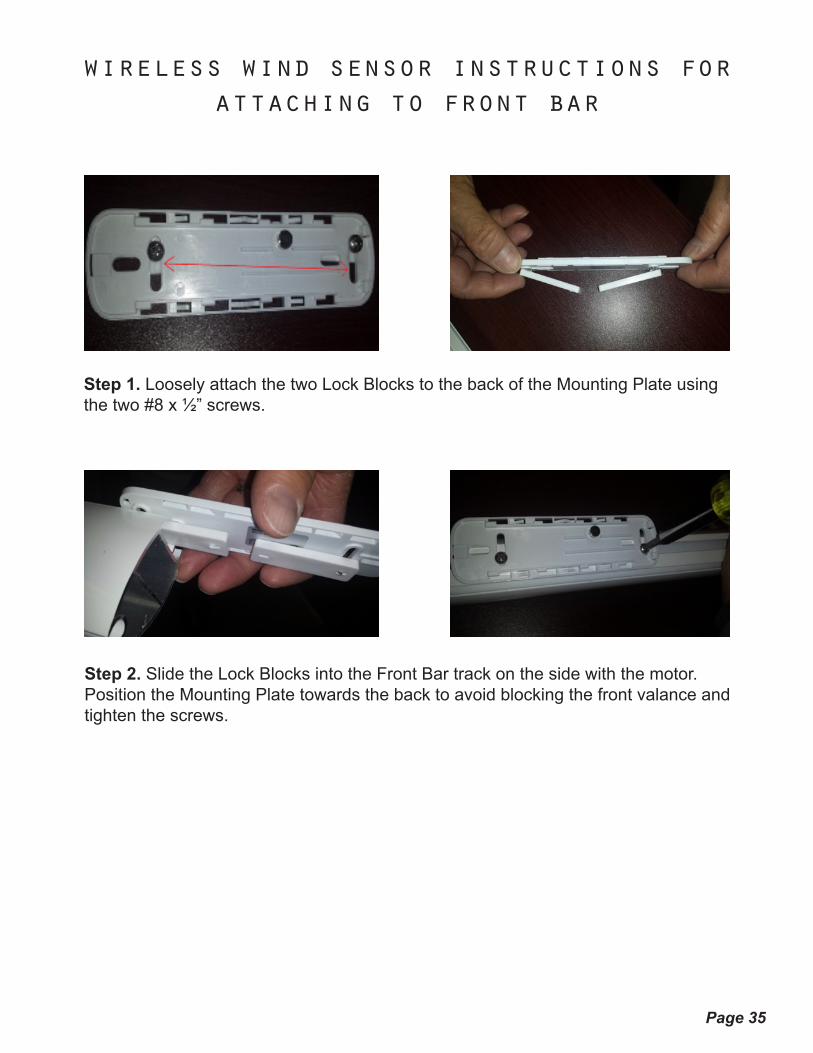
wireless wind sensor instructions for attaching to front bar
Step 1. Loosely attach the two Lock Blocks to the back of the Mounting Plate using the two #8 x ½” screws.
Step 2. Slide the Lock Blocks into the Front Bar track on the side with the motor. Position the Mounting Plate towards the back to avoid blocking the front valance and tighten the screws.
Page 36
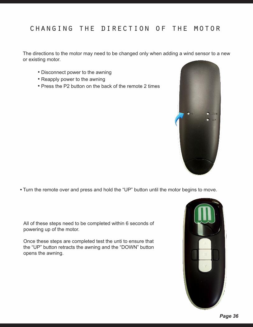
changing the direction of the motor
The directions to the motor may need to be changed only when adding a wind sensor to a new or existing motor.
• Disconnect power to the awning • Reapply power to the awning • Press the P2 button on the back of the remote 2 times
• Turn the remote over and press and hold the “UP” button until the motor begins to move.
All of these steps need to be completed within 6 seconds of powering up of the motor.
Once these steps are completed test the unti to ensure that the “UP” button retracts the awning and the “DOWN” button opens the awning.
Page 37
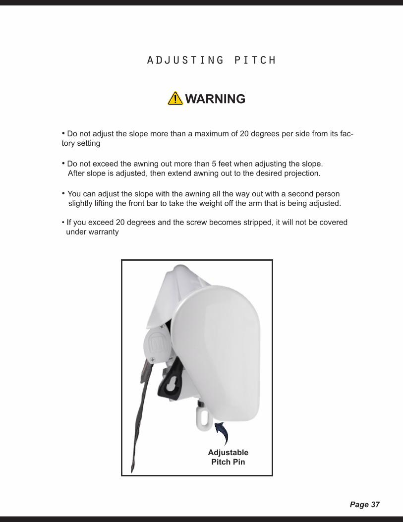
adjusting pitch
WARNING
• Do not adjust the slope more than a maximum of 20 degrees per side from its fac-tory setting
• Do not exceed the awning out more than 5 feet when adjusting the slope. After slope is adjusted, then extend awning out to the desired projection.
• You can adjust the slope with the awning all the way out with a second person slightly lifting the front bar to take the weight off the arm that is being adjusted.
• If you exceed 20 degrees and the screw becomes stripped, it will not be covered under warranty
Adjustable Pitch Pin
Page 38
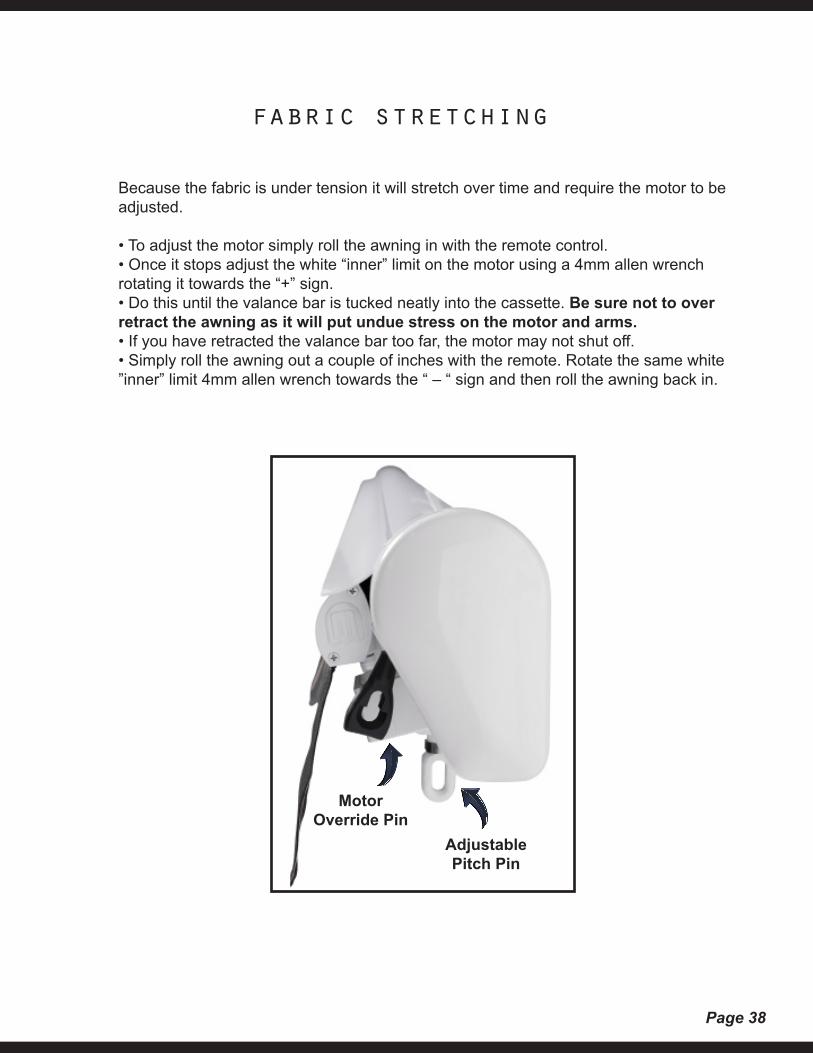
fabric stretching
Because the fabric is under tension it will stretch over time and require the motor to be adjusted.
• To adjust the motor simply roll the awning in with the remote control. • Once it stops adjust the white “inner” limit on the motor using a 4mm allen wrench rotating it towards the “+” sign. • Do this until the valance bar is tucked neatly into the cassette. Be sure not to over retract the awning as it will put undue stress on the motor and arms. • If you have retracted the valance bar too far, the motor may not shut off. • Simply roll the awning out a couple of inches with the remote. Rotate the same white ”inner” limit 4mm allen wrench towards the “ – “ sign and then roll the awning back in.
Adjustable Pitch Pin
MotorOverride Pin
Page 39
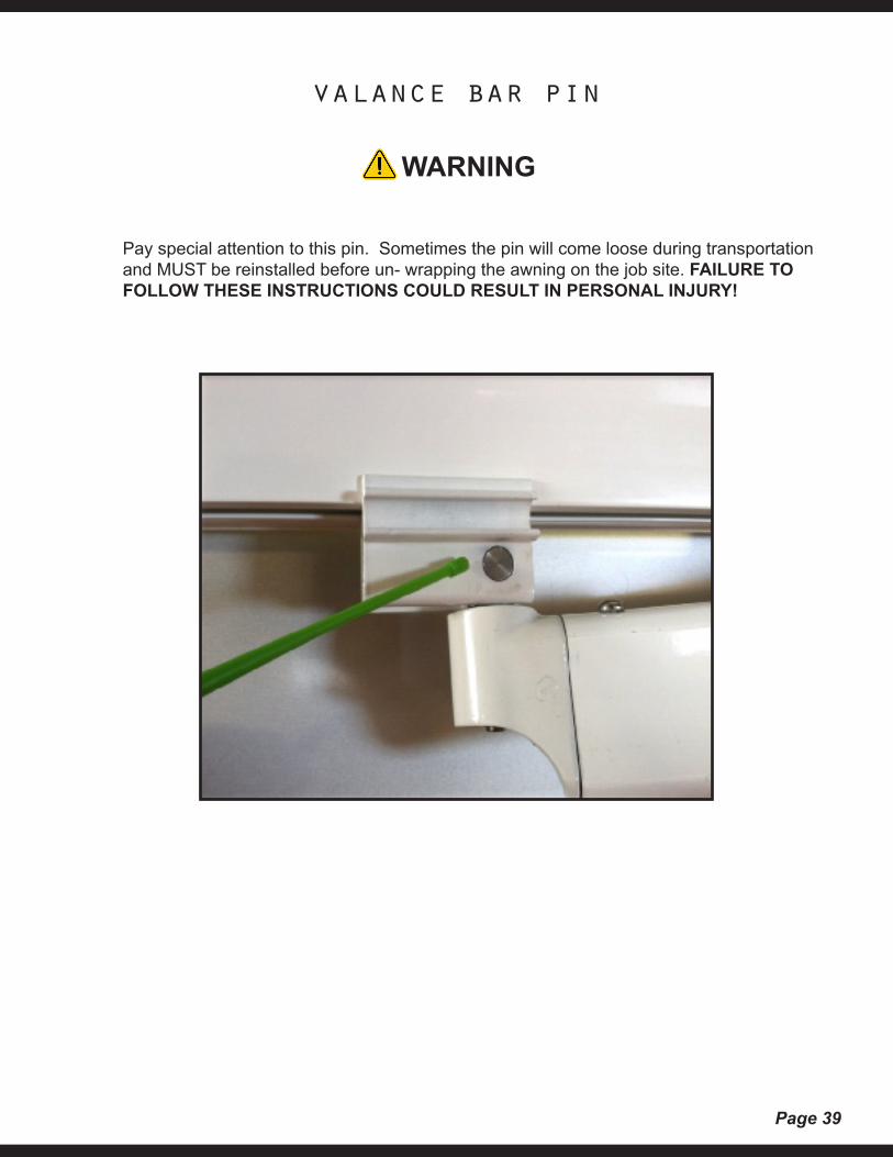
valance bar pin
WARNING
Pay special attention to this pin. Sometimes the pin will come loose during transportation and MUST be reinstalled before un- wrapping the awning on the job site. FAILURE TO FOLLOW THESE INSTRUCTIONS COULD RESULT IN PERSONAL INJURY!