Embed Size (px)
Citation preview
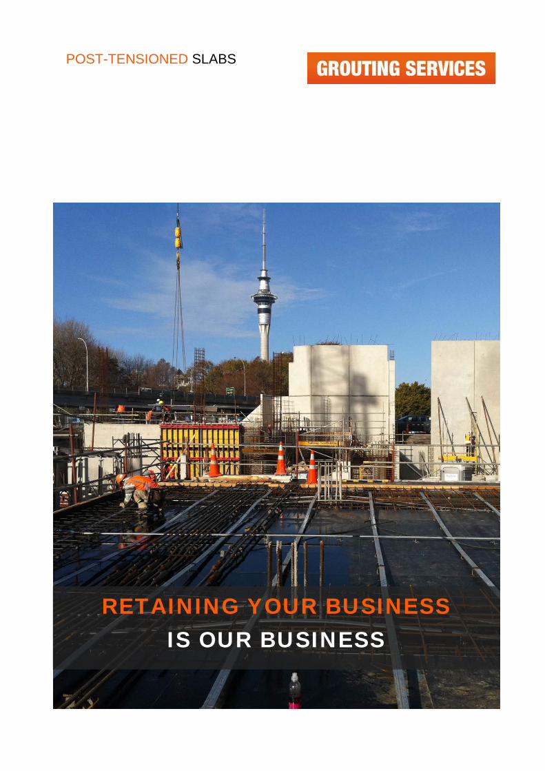
POST-TENSIONED SLABS
RETAINING YOUR BUSINESS
IS OUR BUSINESS
POST-TENSIONED SLABS
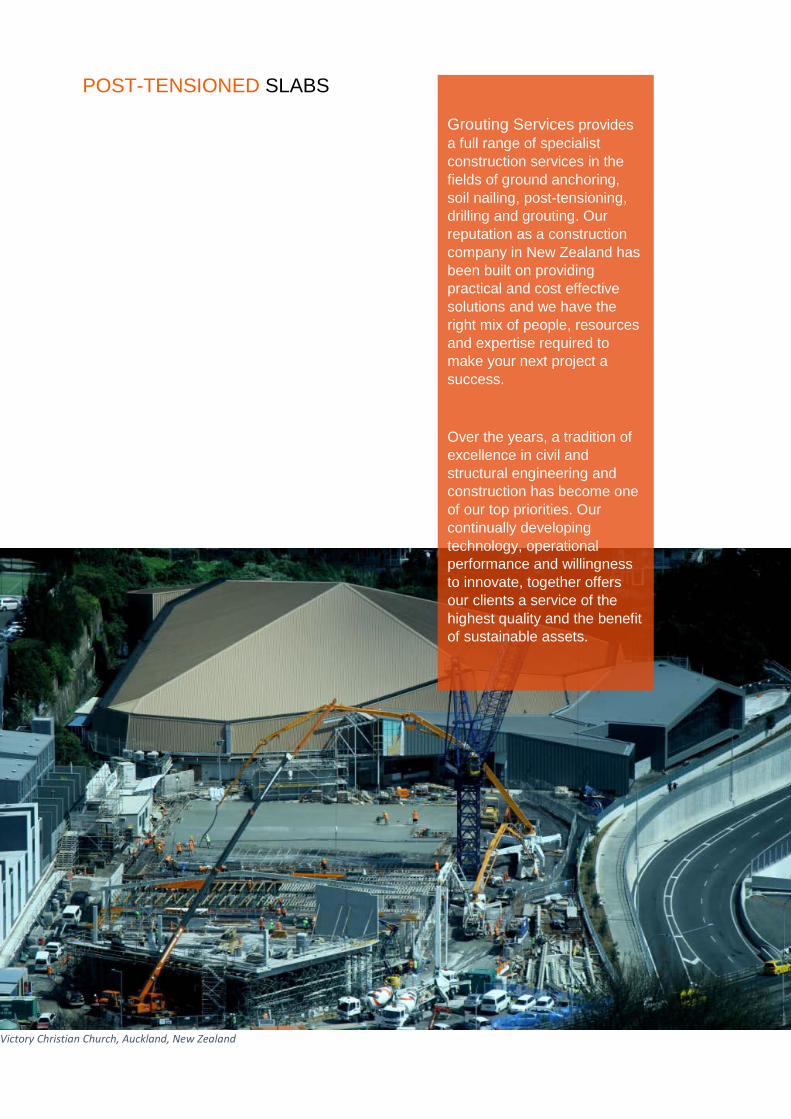
Grouting Services provides a full range of specialist construction services in the fields of ground anchoring, soil nailing, post-tensioning, drilling and grouting. Our reputation as a construction company in New Zealand has been built on providing practical and cost effective solutions and we have the right mix of people, resources and expertise required to make your next project a success.
Over the years, a tradition of excellence in civil and structural engineering and construction has become one of our top priorities. Our continually developing technology, operational performance and willingness to innovate, together offers our clients a service of the highest quality and the benefit of sustainable assets.
Victory Christian Church, Auckland, New Zealand
POST-TENSIONED SLABS
Post-tensioning (PT) is the founding specialist activity of Grouting Services and is a method of reinforcing (strengthening) concrete or other materials with high-strength steel multi-strands or bars, typically referred to as tendons. We have been actively involved in multi-strand and bar stressing for over 30 years and operate the internationally accepted VSL and OVM PT systems.
G-SLAB POST-TENSIONING
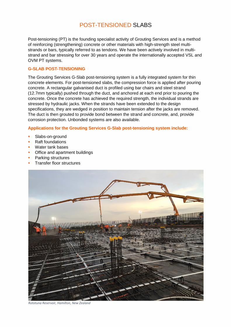
The Grouting Services G-Slab post-tensioning system is a fully integrated system for thin concrete elements. For post-tensioned slabs, the compression force is applied after pouring concrete. A rectangular galvanised duct is profiled using bar chairs and steel strand (12.7mm typically) pushed through the duct, and anchored at each end prior to pouring the concrete. Once the concrete has achieved the required strength, the individual strands are stressed by hydraulic jacks. When the strands have been extended to the design specifications, they are wedged in position to maintain tension after the jacks are removed. The duct is then grouted to provide bond between the strand and concrete, and, provide corrosion protection. Unbonded systems are also available.
Applications for the Grouting Services G-Slab post-tensioning system include:
Slabs-on-ground Raft foundations Water tank bases Office and apartment buildings Parking structures Transfer floor structures
Rototuna Reservoir, Hamilton, New Zealand
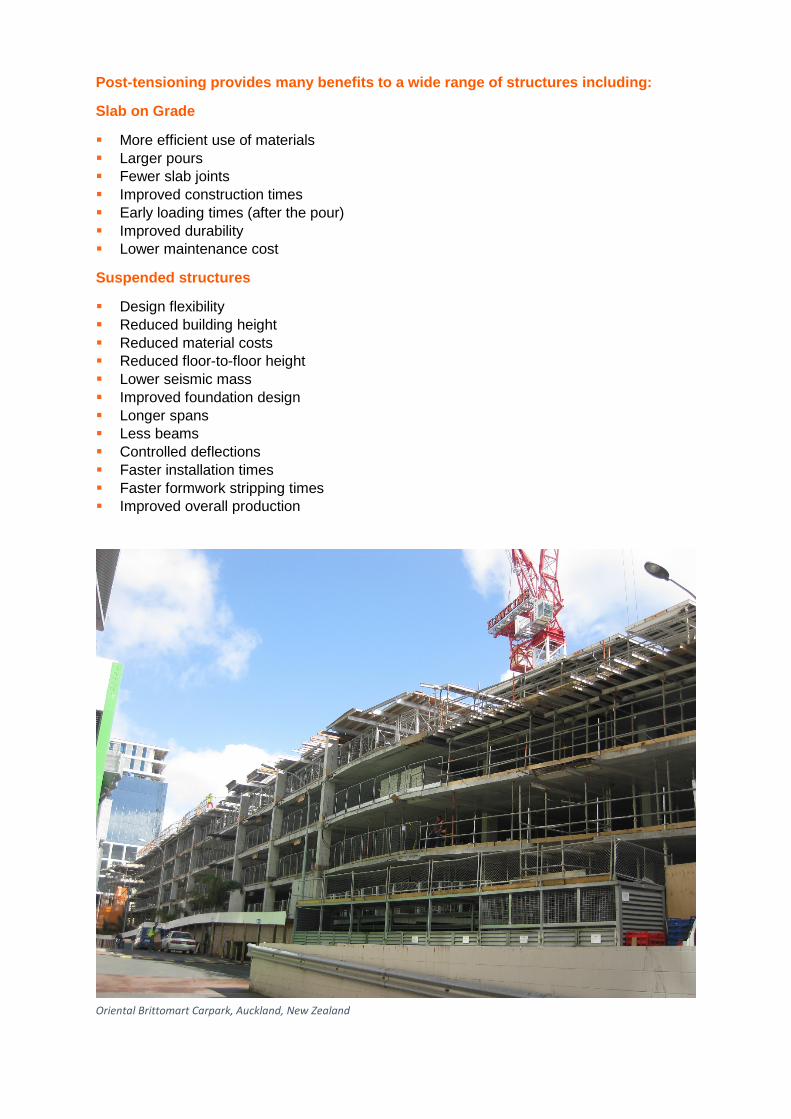
Post-tensioning provides many benefits to a wide range of structures including:
Slab on Grade
More efficient use of materials Larger pours Fewer slab joints Improved construction times Early loading times (after the pour) Improved durability Lower maintenance cost
Suspended structures
Design flexibility Reduced building height Reduced material costs Reduced floor-to-floor height Lower seismic mass Improved foundation design Longer spans Less beams Controlled deflections Faster installation times Faster formwork stripping times Improved overall production
Oriental Brittomart Carpark, Auckland, New Zealand
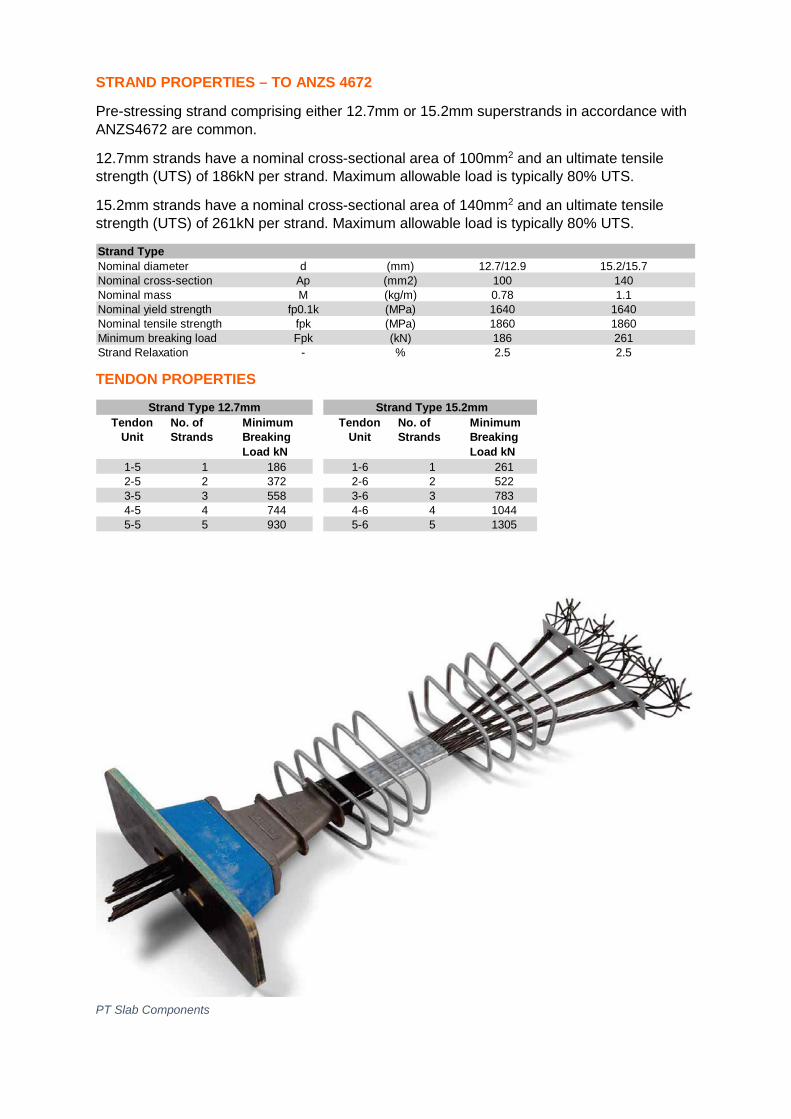
STRAND PROPERTIES – TO ANZS 4672
Pre-stressing strand comprising either 12.7mm or 15.2mm superstrands in accordance with ANZS4672 are common.
12.7mm strands have a nominal cross-sectional area of 100mm2 and an ultimate tensile strength (UTS) of 186kN per strand. Maximum allowable load is typically 80% UTS.
15.2mm strands have a nominal cross-sectional area of 140mm2 and an ultimate tensile strength (UTS) of 261kN per strand. Maximum allowable load is typically 80% UTS.
Strand TypeNominal diameter d (mm) 12.7/12.9 15.2/15.7Nominal cross-section Ap (mm2) 100 140Nominal mass M (kg/m) 0.78 1.1Nominal yield strength fp0.1k (MPa) 1640 1640Nominal tensile strength fpk (MPa) 1860 1860Minimum breaking load Fpk (kN) 186 261Strand Relaxation - % 2.5 2.5
TENDON PROPERTIES
Tendon Unit
No. of Strands
Minimum Breaking Load kN
Tendon Unit
No. of Strands
Minimum Breaking Load kN
1-5 1 186 1-6 1 2612-5 2 372 2-6 2 5223-5 3 558 3-6 3 7834-5 4 744 4-6 4 10445-5 5 930 5-6 5 1305
Strand Type 12.7mm Strand Type 15.2mm
PT Slab Components
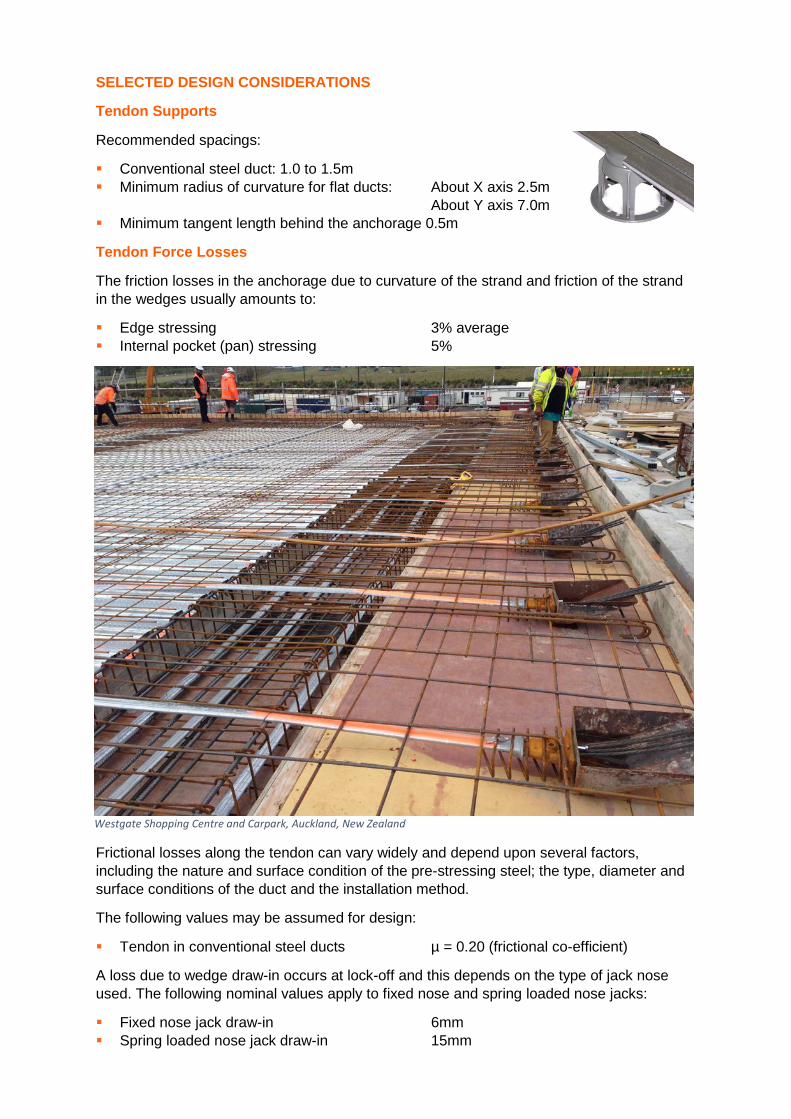
SELECTED DESIGN CONSIDERATIONS
Tendon Supports
Recommended spacings:
Conventional steel duct: 1.0 to 1.5m Minimum radius of curvature for flat ducts: About X axis 2.5m
About Y axis 7.0m Minimum tangent length behind the anchorage 0.5m
Tendon Force Losses
The friction losses in the anchorage due to curvature of the strand and friction of the strand in the wedges usually amounts to:
Edge stressing 3% average Internal pocket (pan) stressing 5%
Frictional losses along the tendon can vary widely and depend upon several factors, including the nature and surface condition of the pre-stressing steel; the type, diameter and surface conditions of the duct and the installation method.
The following values may be assumed for design:
Tendon in conventional steel ducts µ = 0.20 (frictional co-efficient)
A loss due to wedge draw-in occurs at lock-off and this depends on the type of jack nose used. The following nominal values apply to fixed nose and spring loaded nose jacks:
Fixed nose jack draw-in 6mm Spring loaded nose jack draw-in 15mm
Westgate Shopping Centre and Carpark, Auckland, New Zealand
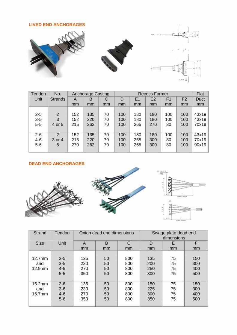
LIVED END ANCHORAGES
Tendon No. Anchorage Casting Recess Former Flat Unit Strands A
mm B
mm C
mm D
mm E1 mm
E2 mm
F1 mm
F2 mm
Duct mm
2-5 2 152 135 70 100 180 180 100 100 43x19 3-5 3 152 220 70 100 180 180 100 100 43x19 5-5 4 or 5 215 262 70 100 265 270 80 100 70x19
2-6 2 152 135 70 100 180 180 100 100 43x19 4-6 3 or 4 215 220 70 100 265 300 80 100 70x19 5-6 5 270 262 70 100 265 300 80 100 90x19
DEAD END ANCHORAGES
Strand Tendon Onion dead end dimensions Swage plate dead end dimensions
Size Unit A mm
B mm
C mm
D mm
E mm
F mm
12.7mm 2-5 135 50 800 135 75 150
and 3-5 230 50 800 200 75 300 12.9mm 4-5 270 50 800 250 75 400
5-5 350 50 800 300 75 500
15.2mm 2-6 135 50 800 150 75 150 and 3-6 230 50 800 225 75 300
15.7mm 4-6 270 50 800 300 75 400 5-6 350 50 800 350 75 500
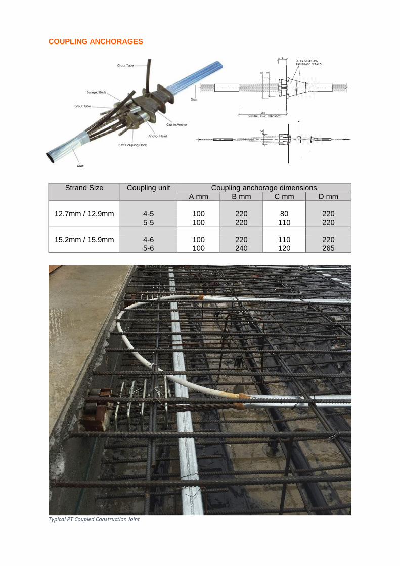
COUPLING ANCHORAGES
Strand Size Coupling unit
Coupling anchorage dimensions A mm B mm C mm D mm
12.7mm / 12.9mm 4-5 100 220 80 220
5-5 100 220 110 220
15.2mm / 15.9mm 4-6 100 220 110 220 5-6 100 240 120 265
Typical PT Coupled Construction Joint
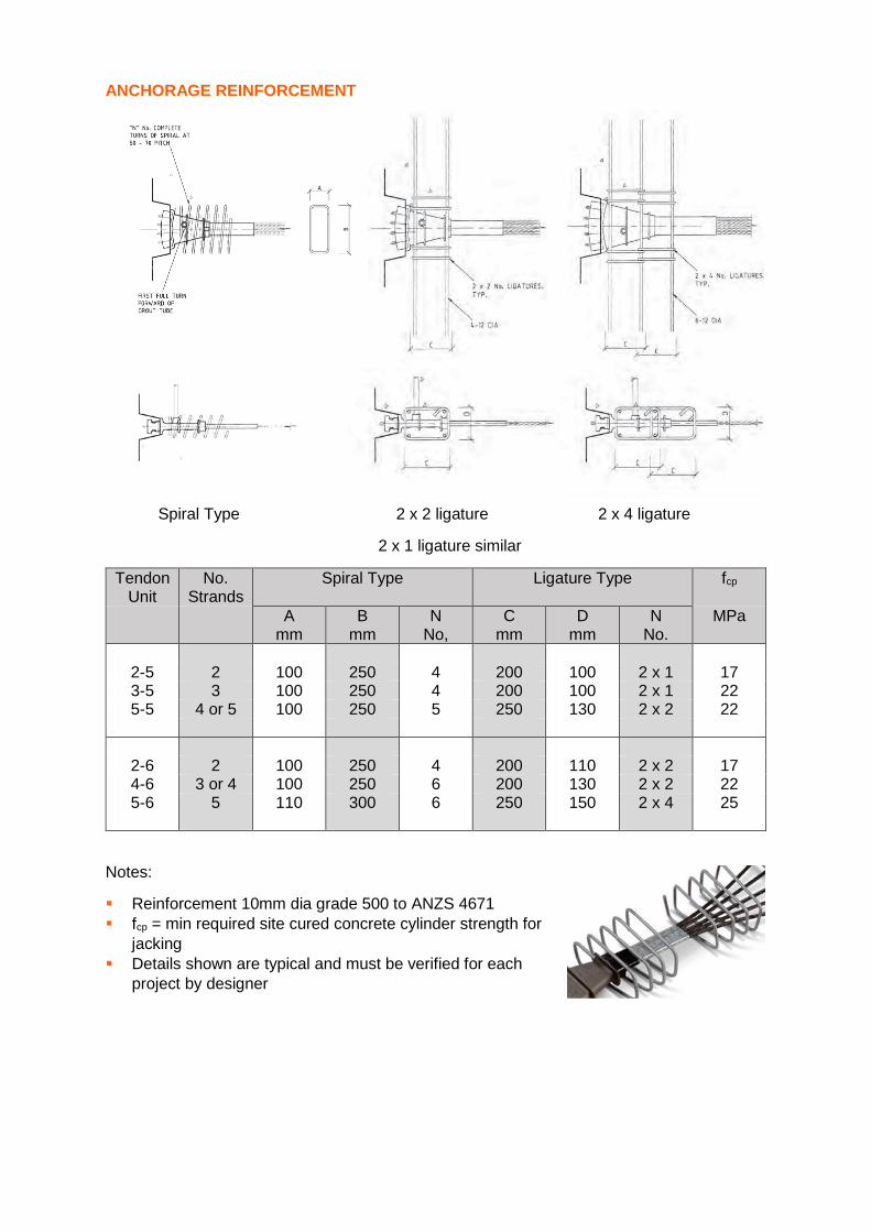
ANCHORAGE REINFORCEMENT
Spiral Type 2 x 2 ligature 2 x 4 ligature
2 x 1 ligature similar
Tendon Unit
No. Strands
Spiral Type Ligature Type fcp
A mm
B mm
N No,
C mm
D mm
N No.
MPa
2-5 2 100 250 4 200 100 2 x 1 17 3-5 3 100 250 4 200 100 2 x 1 22 5-5 4 or 5 100 250 5 250 130 2 x 2 22
2-6 2 100 250 4 200 110 2 x 2 17 4-6 3 or 4 100 250 6 200 130 2 x 2 22 5-6 5 110 300 6 250 150 2 x 4 25
Notes:
Reinforcement 10mm dia grade 500 to ANZS 4671 fcp = min required site cured concrete cylinder strength for
jacking Details shown are typical and must be verified for each
project by designer
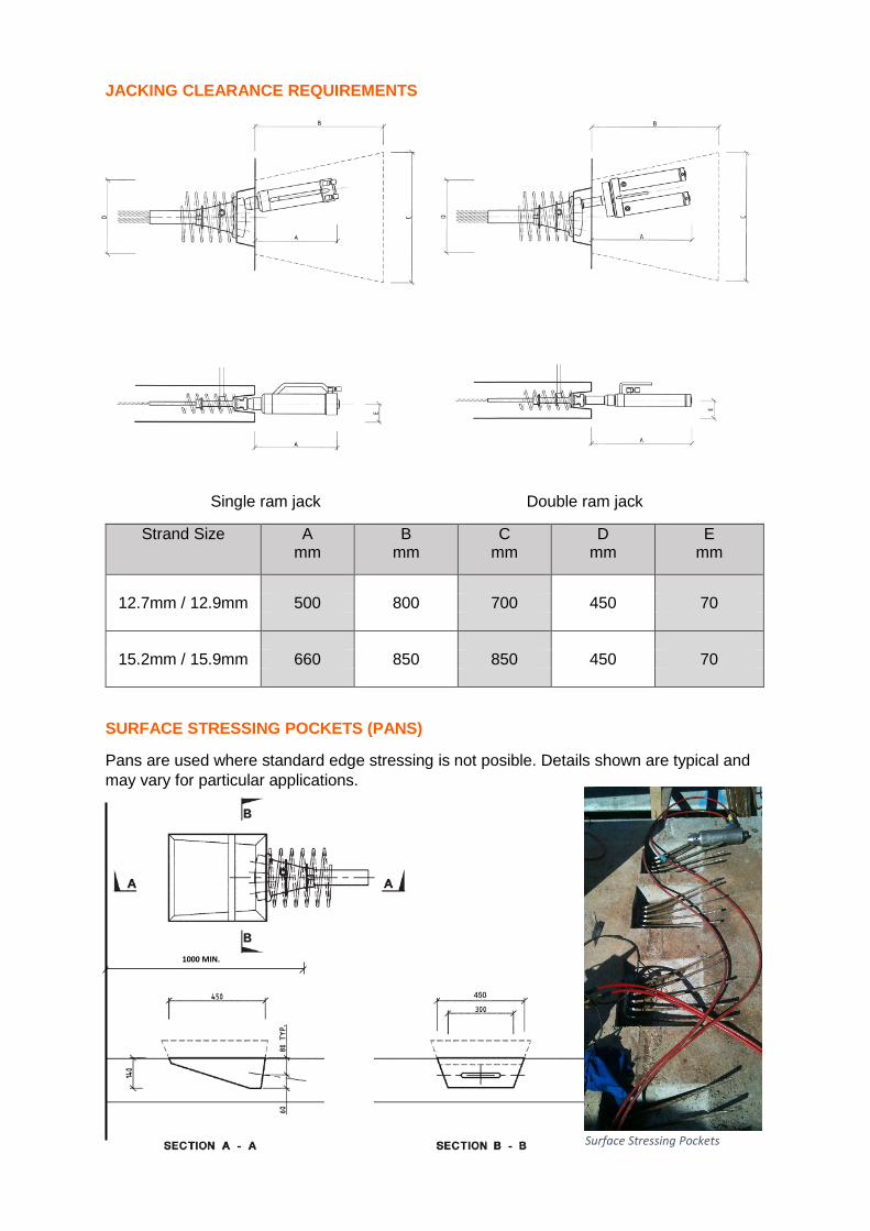
JACKING CLEARANCE REQUIREMENTS
Single ram jack Double ram jack
Strand Size A mm
B mm
C mm
D mm
E mm
12.7mm / 12.9mm 500 800 700 450 70
15.2mm / 15.9mm 660 850 850 450 70
SURFACE STRESSING POCKETS (PANS)
Pans are used where standard edge stressing is not posible. Details shown are typical and may vary for particular applications.
1000 MIN.
Surface Stressing Pockets
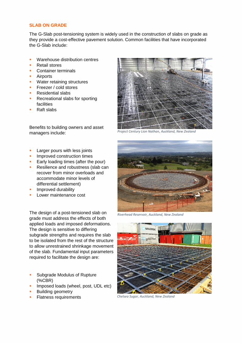
SLAB ON GRADE
The G-Slab post-tensioning system is widely used in the construction of slabs on grade as they provide a cost-effective pavement solution. Common facilities that have incorporated the G-Slab include:
Warehouse distribution centres Retail stores Container terminals Airports Water retaining structures Freezer / cold stores Residential slabs Recreational slabs for sporting
facilities Raft slabs
Benefits to building owners and asset managers include:
Larger pours with less joints Improved construction times Early loading times (after the pour) Resilience and robustness (slab can
recover from minor overloads and accommodate minor levels of differential settlement)
Improved durability Lower maintenance cost
The design of a post-tensioned slab on grade must address the effects of both applied loads and imposed deformations. The design is sensitive to differing subgrade strengths and requires the slab to be isolated from the rest of the structure to allow unrestrained shrinkage movement of the slab. Fundamental input parameters required to facilitate the design are:
Subgrade Modulus of Rupture (%CBR)
Imposed loads (wheel, post, UDL etc) Building geometry Flatness requirements
Project Century Lion Nathan, Auckland, New Zealand
Riverhead Reservoir, Auckland, New Zealand
Chelsea Sugar, Auckland, New Zealand
Design of Slab on Grade
The design of post-tensioned concrete slabs on grade involves a considerable amount of technical expertise based on knowledge and experience. Grouting Services partners in design have more than 30years experience in designing post-tensioned concrete slabs on grade. The following points summarise the design approach used by Grouting Services’ specialist designers for slabs on grade:
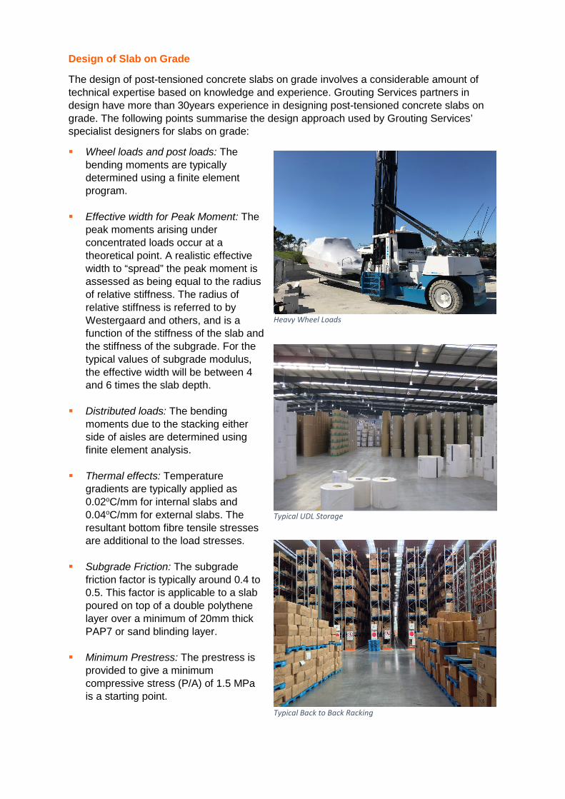
Wheel loads and post loads: The bending moments are typically determined using a finite element program.
Effective width for Peak Moment: The peak moments arising under concentrated loads occur at a theoretical point. A realistic effective width to “spread” the peak moment is assessed as being equal to the radius of relative stiffness. The radius of relative stiffness is referred to by Westergaard and others, and is a function of the stiffness of the slab and the stiffness of the subgrade. For the typical values of subgrade modulus, the effective width will be between 4 and 6 times the slab depth.
Distributed loads: The bending moments due to the stacking either side of aisles are determined using finite element analysis.
Thermal effects: Temperature gradients are typically applied as 0.02oC/mm for internal slabs and 0.04oC/mm for external slabs. The resultant bottom fibre tensile stresses are additional to the load stresses.
Subgrade Friction: The subgrade friction factor is typically around 0.4 to 0.5. This factor is applicable to a slab poured on top of a double polythene layer over a minimum of 20mm thick PAP7 or sand blinding layer.
Minimum Prestress: The prestress is provided to give a minimum compressive stress (P/A) of 1.5 MPa is a starting point.
Heavy Wheel Loads
Typical UDL Storage
Typical Back to Back Racking
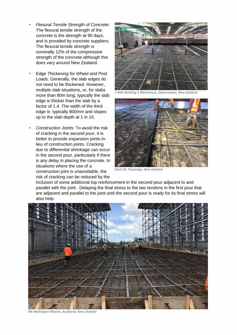
Flexural Tensile Strength of Concrete: The flexural tensile strength of the concrete is the strength at 90 days, and is provided by concrete suppliers. The flexural tensile strength is nominally 12% of the compressive strength of the concrete although this does vary around New Zealand.
Edge Thickening for Wheel and Post Loads: Generally, the slab edges do not need to be thickened. However, multiple slab situations, or, for slabs more than 80m long, typically the slab edge is thicker than the slab by a factor of 1.4. The width of the thick edge is typically 800mm and slopes up to the slab depth at 1 in 10.
Construction Joints: To avoid the risk of cracking in the second pour, it is better to provide expansion joints in-lieu of construction joints. Cracking due to differential shrinkage can occur in the second pour, particularly if there is any delay in placing the concrete. In situations where the use of a construction joint is unavoidable, the risk of cracking can be reduced by the inclusion of some additional top reinforcement in the second pour adjacent to and parallel with the joint. Delaying the final stress to the two tendons in the first pour that are adjacent and parallel to the joint until the second pour is ready for its final stress will also help.
5 Mile Building 5 Warehouse, Queenstown, New Zealand
Shed 16, Tauranga, New Zealand
Mt Wellington Marine, Auckland, New Zealand
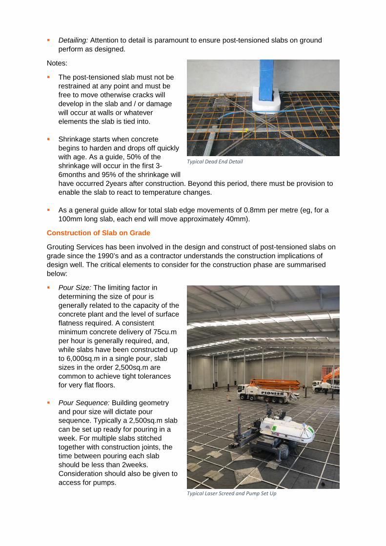
Detailing: Attention to detail is paramount to ensure post-tensioned slabs on ground perform as designed.
Notes:
The post-tensioned slab must not be restrained at any point and must be free to move otherwise cracks will develop in the slab and / or damage will occur at walls or whatever elements the slab is tied into.
Shrinkage starts when concrete begins to harden and drops off quickly with age. As a guide, 50% of the shrinkage will occur in the first 3-6months and 95% of the shrinkage will have occurred 2years after construction. Beyond this period, there must be provision to enable the slab to react to temperature changes.
As a general guide allow for total slab edge movements of 0.8mm per metre (eg, for a
100mm long slab, each end will move approximately 40mm).
Construction of Slab on Grade
Grouting Services has been involved in the design and construct of post-tensioned slabs on grade since the 1990’s and as a contractor understands the construction implications of design well. The critical elements to consider for the construction phase are summarised below:
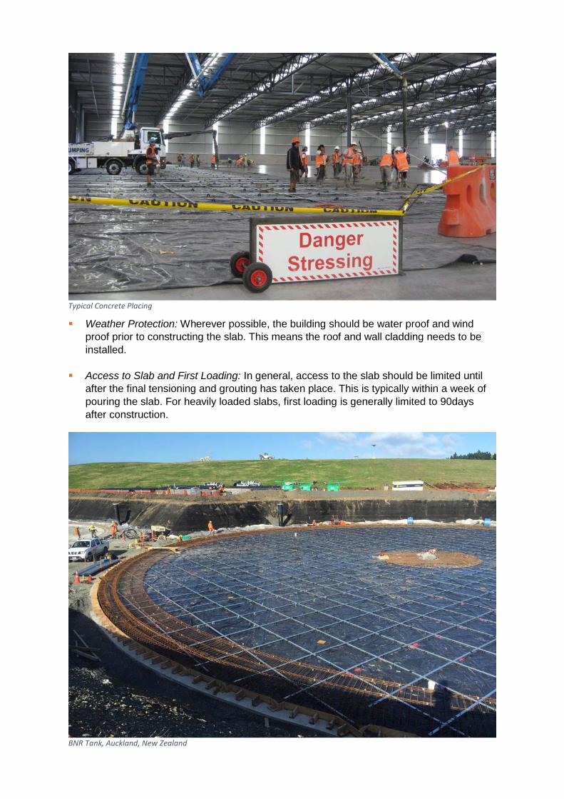
Pour Size: The limiting factor in determining the size of pour is generally related to the capacity of the concrete plant and the level of surface flatness required. A consistent minimum concrete delivery of 75cu.m per hour is generally required, and, while slabs have been constructed up to 6,000sq.m in a single pour, slab sizes in the order 2,500sq.m are common to achieve tight tolerances for very flat floors.
Pour Sequence: Building geometry and pour size will dictate pour sequence. Typically a 2,500sq.m slab can be set up ready for pouring in a week. For multiple slabs stitched together with construction joints, the time between pouring each slab should be less than 2weeks. Consideration should also be given to access for pumps.
Typical Dead End Detail
Typical Laser Screed and Pump Set Up
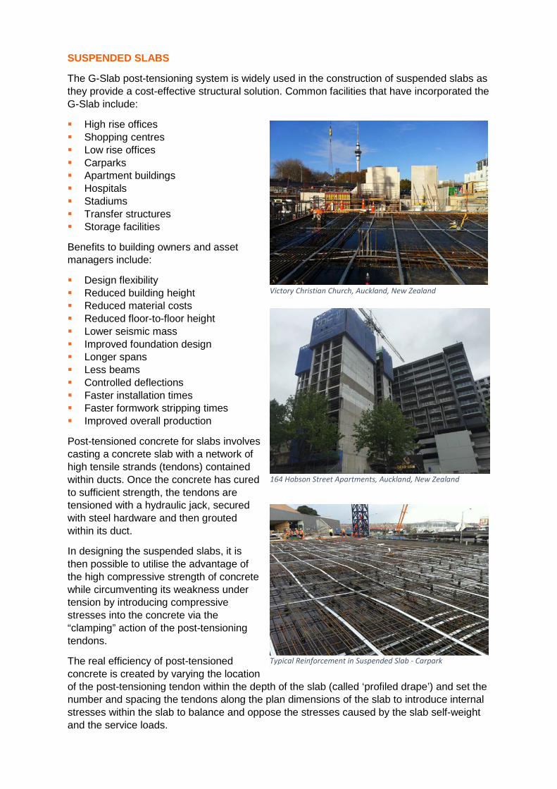
Weather Protection: Wherever possible, the building should be water proof and wind proof prior to constructing the slab. This means the roof and wall cladding needs to be installed.
Access to Slab and First Loading: In general, access to the slab should be limited until after the final tensioning and grouting has taken place. This is typically within a week of pouring the slab. For heavily loaded slabs, first loading is generally limited to 90days after construction.
Typical Concrete Placing
BNR Tank, Auckland, New Zealand
SUSPENDED SLABS
The G-Slab post-tensioning system is widely used in the construction of suspended slabs as they provide a cost-effective structural solution. Common facilities that have incorporated the G-Slab include:
High rise offices Shopping centres Low rise offices Carparks Apartment buildings Hospitals Stadiums Transfer structures Storage facilities
Benefits to building owners and asset managers include:
Design flexibility Reduced building height Reduced material costs Reduced floor-to-floor height Lower seismic mass Improved foundation design Longer spans Less beams Controlled deflections Faster installation times Faster formwork stripping times Improved overall production
Post-tensioned concrete for slabs involves casting a concrete slab with a network of high tensile strands (tendons) contained within ducts. Once the concrete has cured to sufficient strength, the tendons are tensioned with a hydraulic jack, secured with steel hardware and then grouted within its duct.
In designing the suspended slabs, it is then possible to utilise the advantage of the high compressive strength of concrete while circumventing its weakness under tension by introducing compressive stresses into the concrete via the “clamping” action of the post-tensioning tendons.
The real efficiency of post-tensioned concrete is created by varying the location of the post-tensioning tendon within the depth of the slab (called ‘profiled drape’) and set the number and spacing the tendons along the plan dimensions of the slab to introduce internal stresses within the slab to balance and oppose the stresses caused by the slab self-weight and the service loads.
164 Hobson Street Apartments, Auckland, New Zealand
Victory Christian Church, Auckland, New Zealand
Typical Reinforcement in Suspended Slab - Carpark
It is this structural efficiency that results in the following key characteristics:
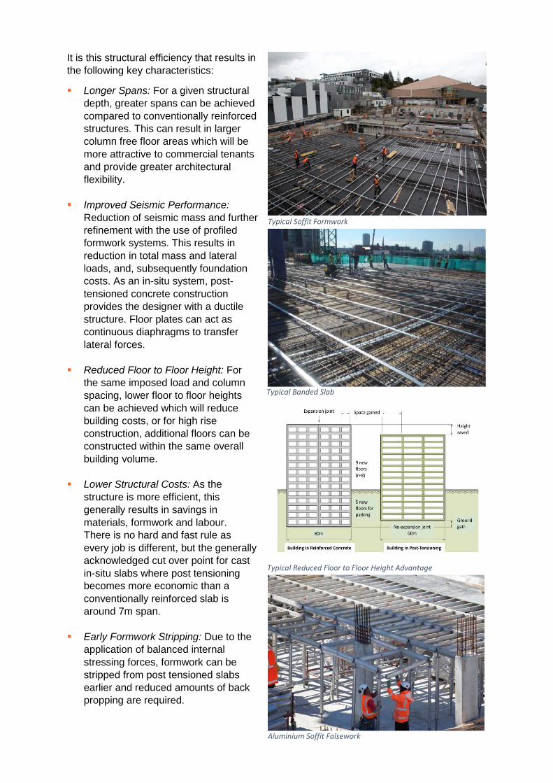
Longer Spans: For a given structural depth, greater spans can be achieved compared to conventionally reinforced structures. This can result in larger column free floor areas which will be more attractive to commercial tenants and provide greater architectural flexibility.
Improved Seismic Performance: Reduction of seismic mass and further refinement with the use of profiled formwork systems. This results in reduction in total mass and lateral loads, and, subsequently foundation costs. As an in-situ system, post-tensioned concrete construction provides the designer with a ductile structure. Floor plates can act as continuous diaphragms to transfer lateral forces.
Reduced Floor to Floor Height: For the same imposed load and column spacing, lower floor to floor heights can be achieved which will reduce building costs, or for high rise construction, additional floors can be constructed within the same overall building volume.
Lower Structural Costs: As the
structure is more efficient, this generally results in savings in materials, formwork and labour. There is no hard and fast rule as every job is different, but the generally acknowledged cut over point for cast in-situ slabs where post tensioning becomes more economic than a conventionally reinforced slab is around 7m span.
Early Formwork Stripping: Due to the application of balanced internal stressing forces, formwork can be stripped from post tensioned slabs earlier and reduced amounts of back propping are required.
Typical Banded Slab
Typical Soffit Formwork
Aluminium Soffit Falsework
Typical Reduced Floor to Floor Height Advantage
Materials Handling: The reduced material quantities in concrete and reinforcement greatly benefit on-site cranage requirements. The strength of post-tensioning strand is approximately 4 times that of conventional reinforcement, therefore the total weight of reinforcing material is greatly reduced.
Column and Footing Design: The
reduction of self-weight and lateral loads may be utilised in more economical design of the supporting columns and foundation system. In multi-storey buildings, reduced column sizes may increase the floor net lettable area.
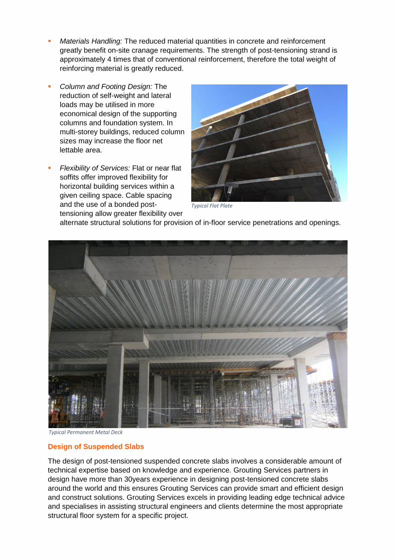
Flexibility of Services: Flat or near flat
soffits offer improved flexibility for horizontal building services within a given ceiling space. Cable spacing and the use of a bonded post-tensioning allow greater flexibility over alternate structural solutions for provision of in-floor service penetrations and openings.
Design of Suspended Slabs
The design of post-tensioned suspended concrete slabs involves a considerable amount of technical expertise based on knowledge and experience. Grouting Services partners in design have more than 30years experience in designing post-tensioned concrete slabs around the world and this ensures Grouting Services can provide smart and efficient design and construct solutions. Grouting Services excels in providing leading edge technical advice and specialises in assisting structural engineers and clients determine the most appropriate structural floor system for a specific project.
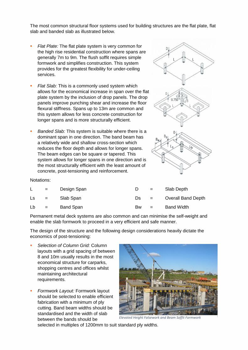
Typical Permanent Metal Deck
Typical Flat Plate
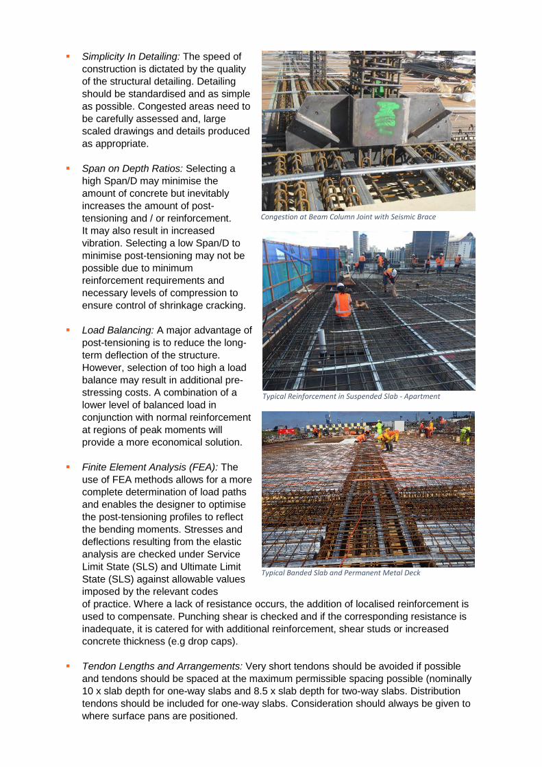
The most common structural floor systems used for building structures are the flat plate, flat slab and banded slab as illustrated below.
Flat Plate: The flat plate system is very common for
the high rise residential construction where spans are generally 7m to 9m. The flush soffit requires simple formwork and simplifies construction. This system provides for the greatest flexibility for under-ceiling services.
Flat Slab: This is a commonly used system which
allows for the economical increase in span over the flat plate system by the inclusion of drop panels. The drop panels improve punching shear and increase the floor flexural stiffness. Spans up to 13m are common and this system allows for less concrete construction for longer spans and is more structurally efficient.
Banded Slab: This system is suitable where there is a dominant span in one direction. The band beam has a relatively wide and shallow cross-section which reduces the floor depth and allows for longer spans. The beam edges can be square or tapered. This system allows for longer spans in one direction and is the most structurally efficient with the least amount of concrete, post-tensioning and reinforcement.
Notations:
L = Design Span D = Slab Depth
Ls = Slab Span Ds = Overall Band Depth
Lb = Band Span Bw = Band Width
Permanent metal deck systems are also common and can minimise the self-weight and enable the slab formwork to proceed in a very efficient and safe manner.
The design of the structure and the following design considerations heavily dictate the economics of post-tensioning:
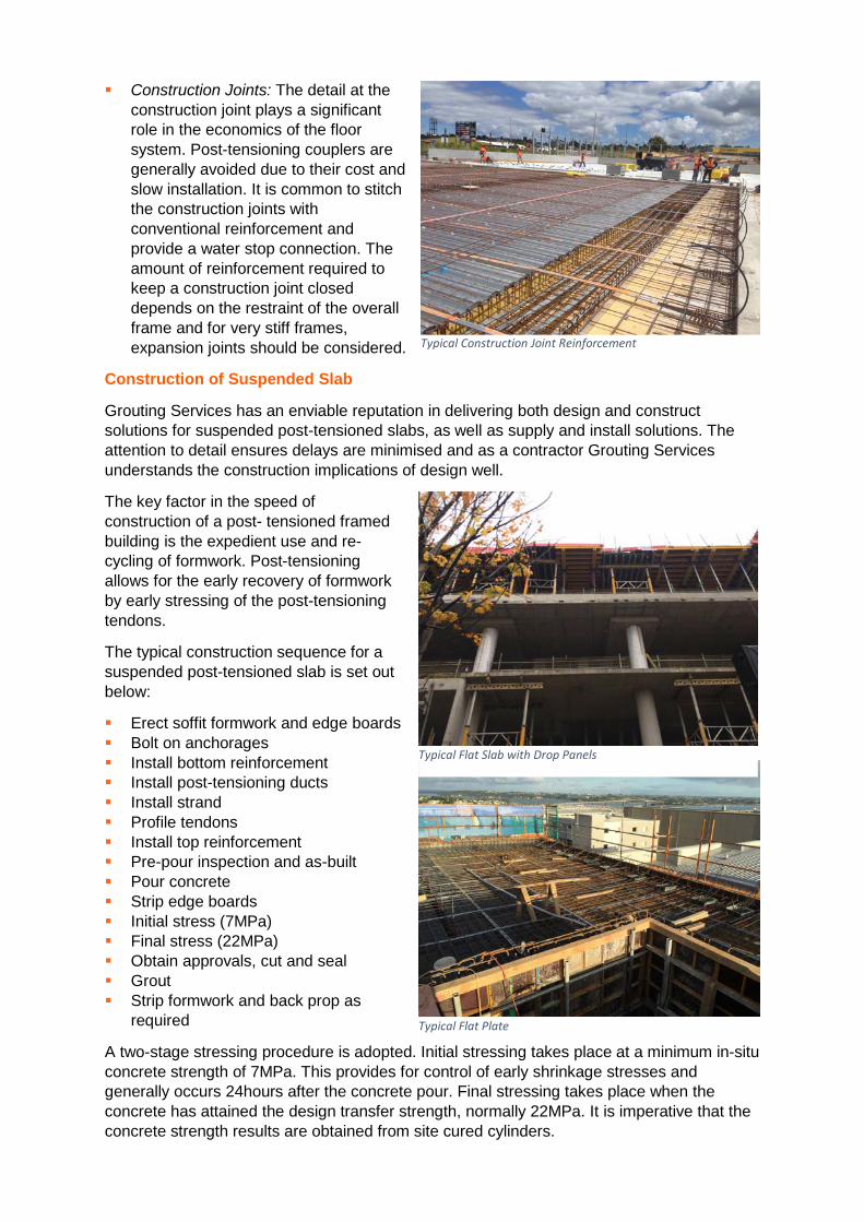
Selection of Column Grid: Column layouts with a grid spacing of between 8 and 10m usually results in the most economical structure for carparks, shopping centres and offices whilst maintaining architectural requirements.
Formwork Layout: Formwork layout should be selected to enable efficient fabrication with a minimum of ply cutting. Band beam widths should be standardised and the width of slab between the bands should be selected in multiples of 1200mm to suit standard ply widths.
Elevated Height Falsework and Beam Soffit Formwork
Simplicity In Detailing: The speed of construction is dictated by the quality of the structural detailing. Detailing should be standardised and as simple as possible. Congested areas need to be carefully assessed and, large scaled drawings and details produced as appropriate.
Span on Depth Ratios: Selecting a high Span/D may minimise the amount of concrete but inevitably increases the amount of post-tensioning and / or reinforcement. It may also result in increased vibration. Selecting a low Span/D to minimise post-tensioning may not be possible due to minimum reinforcement requirements and necessary levels of compression to ensure control of shrinkage cracking.
Load Balancing: A major advantage of post-tensioning is to reduce the long-term deflection of the structure. However, selection of too high a load balance may result in additional pre-stressing costs. A combination of a lower level of balanced load in conjunction with normal reinforcement at regions of peak moments will provide a more economical solution.
Finite Element Analysis (FEA): The use of FEA methods allows for a more complete determination of load paths and enables the designer to optimise the post-tensioning profiles to reflect the bending moments. Stresses and deflections resulting from the elastic analysis are checked under Service Limit State (SLS) and Ultimate Limit State (SLS) against allowable values imposed by the relevant codes of practice. Where a lack of resistance occurs, the addition of localised reinforcement is used to compensate. Punching shear is checked and if the corresponding resistance is inadequate, it is catered for with additional reinforcement, shear studs or increased concrete thickness (e.g drop caps).
Tendon Lengths and Arrangements: Very short tendons should be avoided if possible and tendons should be spaced at the maximum permissible spacing possible (nominally 10 x slab depth for one-way slabs and 8.5 x slab depth for two-way slabs. Distribution tendons should be included for one-way slabs. Consideration should always be given to where surface pans are positioned.
Typical Banded Slab and Permanent Metal Deck
Typical Reinforcement in Suspended Slab - Apartment
Congestion at Beam Column Joint with Seismic Brace
Construction Joints: The detail at the construction joint plays a significant role in the economics of the floor system. Post-tensioning couplers are generally avoided due to their cost and slow installation. It is common to stitch the construction joints with conventional reinforcement and provide a water stop connection. The amount of reinforcement required to keep a construction joint closed depends on the restraint of the overall frame and for very stiff frames, expansion joints should be considered.
Construction of Suspended Slab
Grouting Services has an enviable reputation in delivering both design and construct solutions for suspended post-tensioned slabs, as well as supply and install solutions. The attention to detail ensures delays are minimised and as a contractor Grouting Services understands the construction implications of design well.
The key factor in the speed of construction of a post- tensioned framed building is the expedient use and re-cycling of formwork. Post-tensioning allows for the early recovery of formwork by early stressing of the post-tensioning tendons.
The typical construction sequence for a suspended post-tensioned slab is set out below:
Erect soffit formwork and edge boards Bolt on anchorages Install bottom reinforcement Install post-tensioning ducts Install strand Profile tendons Install top reinforcement Pre-pour inspection and as-built Pour concrete Strip edge boards Initial stress (7MPa) Final stress (22MPa) Obtain approvals, cut and seal Grout Strip formwork and back prop as
required
A two-stage stressing procedure is adopted. Initial stressing takes place at a minimum in-situ concrete strength of 7MPa. This provides for control of early shrinkage stresses and generally occurs 24hours after the concrete pour. Final stressing takes place when the concrete has attained the design transfer strength, normally 22MPa. It is imperative that the concrete strength results are obtained from site cured cylinders.
Typical Construction Joint Reinforcement
Typical Flat Slab with Drop Panels
Typical Flat Plate
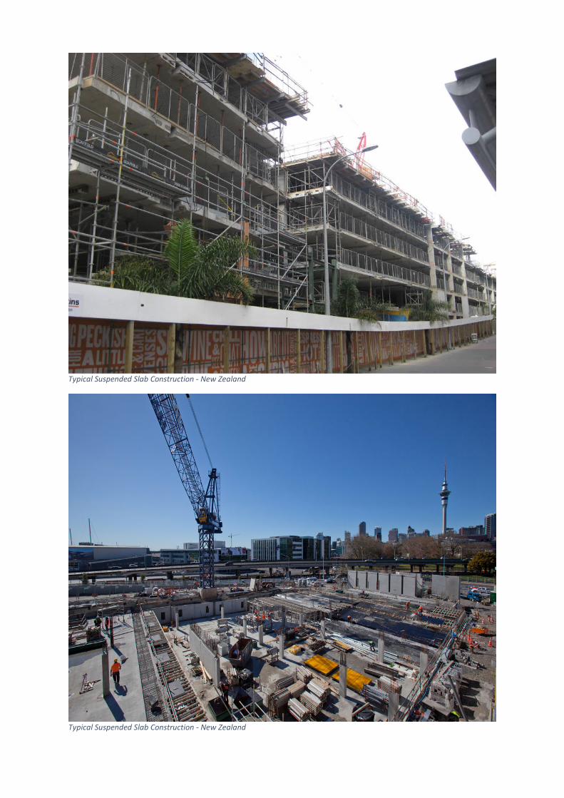
Typical Suspended Slab Construction - New Zealand
Typical Suspended Slab Construction - New Zealand
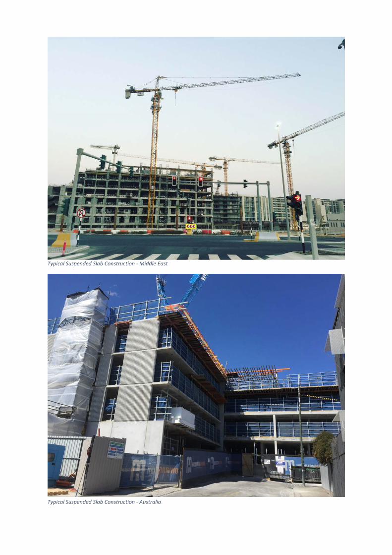
Typical Suspended Slab Construction - Middle East
Typical Suspended Slab Construction - Australia
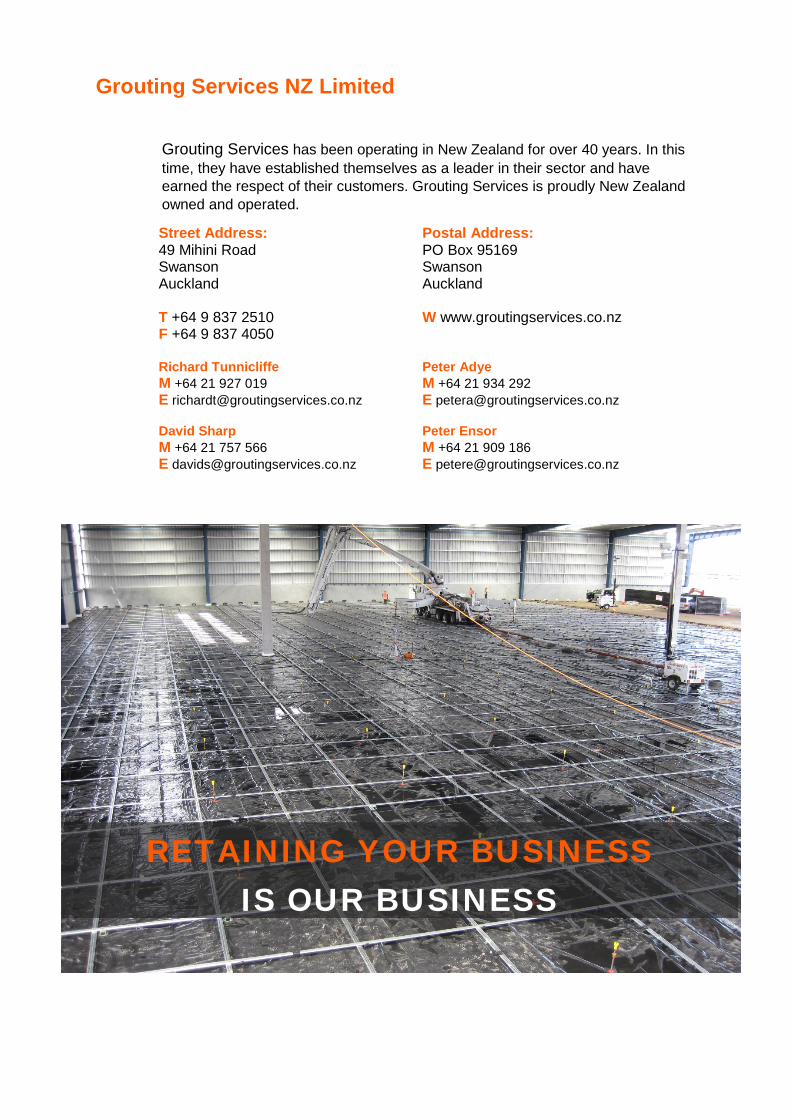
Grouting Services NZ Limited
Grouting Services has been operating in New Zealand for over 40 years. In this time, they have established themselves as a leader in their sector and have earned the respect of their customers. Grouting Services is proudly New Zealand owned and operated.
Street Address: 49 Mihini Road Swanson Auckland T +64 9 837 2510 F +64 9 837 4050 Richard Tunnicliffe M +64 21 927 019 E [email protected] David Sharp M +64 21 757 566 E [email protected]
Postal Address: PO Box 95169 Swanson Auckland W www.groutingservices.co.nz Peter Adye M +64 21 934 292 E [email protected] Peter Ensor M +64 21 909 186 E [email protected]
RETAINING YOUR BUSINESS
IS OUR BUSINESS