Embed Size (px)
Citation preview


Techical Design Guide | Earth Retaining Walls
TDG-ERW-01 Sept 2017 Page 2
a. Select the appropriate design table(s) dependingon whether or not there are fences located abovethe retaining wall. Go to Section 3.1 or 4.1 of thisdocument for retaining walls without fences aboveand Section 3.2 or 4.2 for retaining walls with fencesabove (up to a maximum of 1.8m high fence). It isnoted that for retaining walls with fences above,refer to both Section 3.2.1 or 4.2.1 for general fencezones and Section 3.3.1 or 4.3.1 for the end zonesof a fence (i.e. within 7.2 metres from the end of afence).
b. Select the correct design table based on thebackfill/subgrade material to be used for theretaining wall. 5 Different subgrade/backfillmaterials have been catered for, namely:
• Gravel;• Medium Dense Sand (Medium grained);• Medium Dense Silty Sand/Fine Sand/Shales;• Stiff Clay; or• Soft Clay Note: We recommend for walls greater than2m height, geotechnical advice be soughtto verify the nature of the subgrade/backfillmaterials to be adopted for the design.
c. The subgrade is the material into which the postis to be embedded and the backfill is the materialwhich is placed and compacted behind the retainingwall.
d. Determine the actual height of the wall based onon-site measurements/survey.
e. Determine the maximum post spacing for the wallheight by referring to the relevant table(s) fromStep a). Choose the post spacing for which themaximum wall height is greater than the actual wallheight determined in Step c).
f. Determine the minimum post embedment depthbased on the selected subgrade/backfill type, wallheight, and post spacing.
Example:
Step 1. An earth retaining wall with a 1,800mm high fence: Go to Section 3.2.1 for the general fence zones (away from the end of the fence).
Step 2. Select the correct backfill/subgrade material: Gravel
Step 3. Actual wall height: 1,100mm
Step 4. Select the post spacing: 2,000mm (the maximum wall height for that spacing is 1,200mm which is greater than the required wall height).
Step 5. Select the minimum post embedment depth: 1,000mm.
Step 6. Repeat Steps 1 to 5 for the end zones of a fence by referring to Section 3.3.1.
RETAINING WALL SELECTION PROCEDURE1

Techical Design Guide | Earth Retaining Walls
TDG-ERW-01 Sept 2017 Page 3
The general configuration of the wall with drainage installed behind the wall should generally conform to the diagram above.
Typical wall configurationFigure 1
• Reinforced concrete sleepers are manufactured from naturally occurring and man made constituents,
variations in colour may occur from batch to batch.
• Reinforced concrete sleepers can exhibit hairline cracking given the inherent nature of the materials
from which they are manufactured. Hairline cracks on the front face of the sleepers are not indicative of
an ultimate strength failure. The structural design of the sleepers are based on a maximum deflection of
span/125 under serviceability limit state loads, where the span is the distance between post centres.
• Special care must be taken when using 2.4m sleepers.
• Over compaction can result in the sleeper bowing and or cracking.
• Please note that sleepers are heavy and safe lifting procedure must be adhered to.
IMPORTANT TO NOTE

Techical Design Guide | Earth Retaining Walls
TDG-ERW-01 Sept 2017 Page 4
POST SPACING AND EMBEDMENT DEPTH DESIGN TABLES
EARTH RETAINING WALL WITHOUT FENCES ABOVE100UC14.8 POSTS IN 400MM Ø POST HOLES
EMBEDMENT DEPTH VARIATION TABLE
3
3.1
Backfill Material/Subgrade Material
Post Spacing (mm)Maximum Wall Height
(mm)Minimum Post
Embedment Depth (mm)
Gravel
1000
1200
1600
2000
2400
2450
2300
2050
1850
1100
1050
1050
1050
1050
750
Medium Dense Sand
(Medium Grained)
1000
1200
1600
2000
2400
2250
2100
1850
1700
1400
1150
1150
1150
1200
1100
Silty Sand
Fine Sand
Shales
1000
1200
1600
2000
2400
2200
2050
1800
1650
1436
1300
1300
1300
1350
1250
Stiff Clay
1000
1200
1600
2000
2400
2100
1950
1700
1550
1067
1250
1050
1050
1050
750
Soft Clay
1000
1200
1600
2000
2400
1850
1700
1500
1350
972
2050
2050
2050
2100
1550
% Reduction in Wall Height
% Reduction in Embedment Depth
No Fence With Fence - GeneralZones With Fence - End Zones
10% 9% 3% 1%
20% 18% 6% 2%
30% 27% 9% 2%
40% 36% 12% 3%
50% 45% 15% 4%
Embedment of retaining wall posts within rock are not permitted.
HARD SOUND IGNEOUS ROCK2

Techical Design Guide | Earth Retaining Walls
TDG-ERW-01 Sept 2017 Page 5
EARTH RETAINING WALLS WITH FENCES ABOVE (MAX 1800MM HEIGHT)3.2
GENERAL ZONES (AWAY FROM THE END OF A FENCE)100UC14.8 POSTS IN 400MM Ø POSTS HOLES
3.2.1
Backfill Material/Subgrade Material Post Spacing (mm) Maximum Wall Height
(mm)Minimum Post
Embedment Depth (mm)
Gravel
1000
1200
1600
2000
2400
1950
1750
1450
1200
1000
1000
1000
1000
1000
1000
Medium Dense Sand
(Medium Grained)
1000
1200
1600
2000
2400
1850
1650
1350
1100
950
1150
1150
1150
1150
1150
Silty Sand
Fine Sand
Shales
1000
1200
1600
2000
2400
1800
1600
1300
1100
900
1300
1300
1300
1300
1300
Stiff Clay
1000
1200
1600
2000
2400
1700
1550
1250
1050
900
1000
1000
1000
1000
1050
Soft Clay
1000
1200
1600
2000
2400
1550
1350
1100
900
750
2000
2000
1950
1950
1950
EMBEDMENT DEPTH VARIATION TABLE
% Reduction in Wall Height
% Reduction in Embedment Depth
No FenceWith Fence - General
ZonesWith Fence - End Zones
10% 9% 3% 1%
20% 18% 6% 2%
30% 27% 9% 2%
40% 36% 12% 3%
50% 45% 15% 4%

Techical Design Guide | Earth Retaining Walls
TDG-ERW-01 Sept 2017 Page 6
EARTH RETAINING WALLS END ZONES (WITHIN 7.2M FROM THE END OF THE FENCE)3.3
EARTH RETAINING WALL100UC14.8 POSTS IN 400MM Ø POST HOLES
3.3.1
Backfill Material/Subgrade Material
Post Spacing (mm)Maximum Wall Height
(mm)Minimum Post
Embedment Depth (mm)
Gravel
1000
1200
1600
2000
2400
2450
2300
2050
1850
1100
1050
1050
1050
1050
750
Medium Dense Sand
(Medium Grained)
1000
1200
1600
2000
2400
2250
2100
1850
1700
1400
1150
1150
1150
1200
1100
Silty Sand
Fine Sand
Shales
1000
1200
1600
2000
2400
2200
2050
1800
1650
1436
1300
1300
1300
1350
1250
Stiff Clay
1000
1200
1600
2000
2400
2100
1950
1700
1550
1067
1250
1050
1050
1050
750
Soft Clay
1000
1200
1600
2000
2400
1850
1700
1500
1350
972
2050
2050
2050
2100
1550
EMBEDMENT DEPTH VARIATION TABLE
% Reduction in Wall Height
% Reduction in Embedment Depth
No Fence With Fence - GeneralZones With Fence - End Zones
10% 9% 3% 1%
20% 18% 6% 2%
30% 27% 9% 2%
40% 36% 12% 3%
50% 45% 15% 4%

Techical Design Guide | Earth Retaining Walls
TDG-ERW-01 Sept 2017 Page 7
POST SPACING AND EMBEDMENT DEPTH DESIGN TABLES4
EARTH RETAINING WALL WITHOUT FENCES ABOVE150UC23 POSTS IN 450MM Ø POST HOLES
4.1
Backfill Material/Subgrade Material
Post Spacing (mm)Maximum Wall Height
(mm)Minimum Post
Embedment Depth (mm)
Gravel
1000
1200
1600
2000
2400
3350
3100
2800
2550
1700
1300
1300
1350
1350
1000
Medium Dense Sand
(Medium Grained)
1000
1200
1600
2000
2400
3100
2850
2550
2350
1400
1500
1500
1500
1500
1100
Silty Sand
Fine Sand
Shales
1000
1200
1600
2000
2400
3050
2850
2500
2300
1450
1700
1700
1700
1700
1250
Stiff Clay
1000
1200
1600
2000
2400
2800
2600
2350
1800
1050
1500
1500
1550
1250
800
Soft Clay
1000
1200
1600
2000
2400
2500
2300
2000
1650
950
2900
2900
2900
2550
1500
EMBEDMENT DEPTH VARIATION TABLE
% Reduction in Wall Height
% Reduction in Embedment Depth
No Fence With Fence - GeneralZones With Fence - End Zones
10% 9% 6% 3%
20% 18% 12% 7%
30% 25% 16% 10%
40% 33% 21% 14%
50% 41% 25% 17%
Techical Design Guide | Earth Retaining Walls
TDG-ERW-01 Sept 2017 Page 8
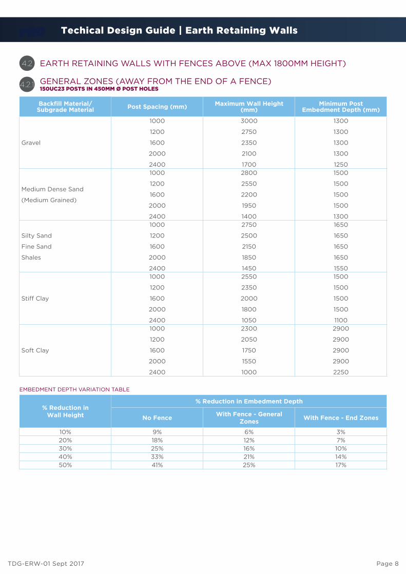
EARTH RETAINING WALLS WITH FENCES ABOVE (MAX 1800MM HEIGHT)4.2
GENERAL ZONES (AWAY FROM THE END OF A FENCE)150UC23 POSTS IN 450MM Ø POST HOLES
4.2.1
Backfill Material/Subgrade Material Post Spacing (mm) Maximum Wall Height
(mm)Minimum Post
Embedment Depth (mm)
Gravel
1000
1200
1600
2000
2400
3000
2750
2350
2100
1700
1300
1300
1300
1300
1250
Medium Dense Sand
(Medium Grained)
1000
1200
1600
2000
2400
2800
2550
2200
1950
1400
1500
1500
1500
1500
1300
Silty Sand
Fine Sand
Shales
1000
1200
1600
2000
2400
2750
2500
2150
1850
1450
1650
1650
1650
1650
1550
Stiff Clay
1000
1200
1600
2000
2400
2550
2350
2000
1800
1050
1500
1500
1500
1500
1100
Soft Clay
1000
1200
1600
2000
2400
2300
2050
1750
1550
1000
2900
2900
2900
2900
2250
EMBEDMENT DEPTH VARIATION TABLE
% Reduction in Wall Height
% Reduction in Embedment Depth
No FenceWith Fence - General
ZonesWith Fence - End Zones
10% 9% 6% 3%
20% 18% 12% 7%
30% 25% 16% 10%
40% 33% 21% 14%
50% 41% 25% 17%

Techical Design Guide | Earth Retaining Walls
TDG-ERW-01 Sept 2017 Page 9
EARTH RETAINING WALLS END ZONES (WITHIN 7.2M FROM THE END OF THE FENCE)4.3
150UC23 POSTS IN 450MM Ø POST HOLES4.3.1
Backfill Material/Subgrade Material
Post Spacing (mm)Maximum Wall Height
(mm)Minimum Post
Embedment Depth (mm)
Gravel
1000
1200
1600
2000
2400
2650
2400
1950
1650
1400
1300
1300
1300
1300
1300
Medium Dense Sand
(Medium Grained)
1000
1200
1600
2000
2400
2500
2250
1850
1500
1300
1450
1450
1450
1450
1450
Silty Sand
Fine Sand
Shales
1000
1200
1600
2000
2400
2450
2200
1800
1500
1250
1650
1650
1650
1650
1650
Stiff Clay
1000
1200
1600
2000
2400
2300
2050
1700
1450
1100
1500
1500
1500
1500
1500
Soft Clay
1000
1200
1600
2000
2400
2000
1750
1400
1150
1000
2700
2700
2700
2700
2700
EMBEDMENT DEPTH VARIATION TABLE
% Reduction in Wall Height
% Reduction in Embedment Depth
No Fence With Fence - GeneralZones With Fence - End Zones
10% 9% 6% 3%
20% 18% 12% 7%
30% 25% 16% 10%
40% 33% 21% 14%
50% 41% 25% 17%

Techical Design Guide | Earth Retaining Walls
TDG-ERW-01 Sept 2017 Page 10
EARTH RETAINING WALLS END ZONES (WITHIN 7.2M FROM THE END OF THE FENCE)4.3
150UC23 POSTS IN 450MM Ø POST HOLES4.3.1
Backfill Material/
Subgrade MaterialPost Spacing (mm)
Maximum Wall Height
(mm)
Minimum Post
Embedment Depth (mm)
Gravel
1000
1200
1600
2000
2400
2650
2400
1950
1650
1400
1300
1300
1300
1300
1300
Medium Dense Sand
(Medium Grained)
1000
1200
1600
2000
2400
2500
2250
1850
1500
1300
1450
1450
1450
1450
1450
Silty Sand
Fine Sand
Shales
1000
1200
1600
2000
2400
2450
2200
1800
1500
1250
1650
1650
1650
1650
1650
Stiff Clay
1000
1200
1600
2000
2400
2300
2050
1700
1450
1100
1500
1500
1500
1500
1500
Soft Clay
1000
1200
1600
2000
2400
2000
1750
1400
1150
1000
2700
2700
2700
2700
2700
EMBEDMENT DEPTH VARIATION TABLE
% Reduction in Wall Height
% Reduction in Embedment Depth
No FenceWith Fence - General
ZonesWith Fence - End Zones
10% 9% 6% 3%
20% 18% 12% 7%
30% 25% 16% 10%
40% 33% 21% 14%
50% 41% 25% 17%

Techical Design Guide | Earth Retaining Walls
TDG-ERW-01 Sept 2017 Page 11
Embedment depths for cantilever retaining walls is critical. A small reduction in embedment depth results in a significant increase in stress within the foundation material and increases the likelihood of a foundation failure. Accordingly embedment depths noted within this document are considered minimum values.
The figures given in Tables 3.1, 3.2.1, 3.3.1, 4.1, 4.2.1 and 4.3.1 assume that the same soil type is used for both backfill and subgrade embedment.
The formulation of the cantilever retaining walls within this document have been undertaken based on the following soil parameters:
The sizes and dimensions shown for the tables in Section 3 and 4 of this document have been based on a Type 3 structure classification to AS4678- 2002. This assumes that failure of this type of structure would only result in minimal damage and loss of access. For higher structure classifications, engineering advice should be obtained.
The tables shown in Section 3 and 4 of this document assumes that the backfill behind the retaining wall is placed in a manner which is consistent with Controlled Fill - Class 1 as per AS 4678-2002. The levels of compaction required to achieve this would be 98% of standard dry density in maximum 200mm compacted layers at optimum moisture content +/- 2%. Failure to install the backfill material in a manner which is consistent with the above will void all warranty and structural certification. For retaining walls where it is intended to place and compact the backfill consistent with a lower classification, engineering advice should be obtained.
All steel posts shall be 100UC14.8 or 150UC23 Grade 300 unless noted otherwise (refer Table 3 and 4). The post holes into which these members are placed shall be of a minimum diameter of 400mm or 450mm with minimum 100mm concrete cover at base of hole (refer Table 3 and 4). Minimum concrete grade in post hole to be 25MPa at 28 days.
The sleepers used within these retaining walls consist of precast concrete 75mm thick and 200mm high. Minimum concrete strengths shall be 40 MPa at 28 days. Each sleeper shall be reinforced with 2 N12 reinforcing bars longitudinal, with minimum 30mm cover.
• Allow minimum 48 hours for concrete to set in post holes prior to installing sleepers.
• Ensure horizontal alignment and correct height spacing prior to inserting sleepers into posts. Use packing under bottom row of sleepers if required.
• Place geotextile to rear face of sleepers to prevent drainage material from flowing through the small gaps between the sleepers. Lay slotted rigid PVC pipe behind the sleepers connected to stormwater as detailed in Typical Wall Configuration diagram (figure 1).
NOTES ON TABLES SOIL PARAMETERS
POST AND SLEEPER SIZES
EMBEDMENT DEPTHS
INSTALLATION NOTES
4.4 5
6
4.4.1
4.4.2
Subgrade/Backfill Type
Density(kN/m3)
Angle ofInternalFriction
Cohesion(kPa)
Gravel 19 35 -
Sand 20 32 -
Silty Sand 18 30 -
Stiff Clay 20 - 75
Soft Clay 18 - 18

Techical Design Guide | Earth Retaining Walls
TDG-ERW-01 Sept 2017 Page 12
Figure 2
The retaining walls specified in this document have been designed based on a 2.5kPa surcharge load in accordance with AS4678-2002. For retaining walls where a higher surcharge loading is required or where the retaining wall is within the zone of influence of other structures (refer to Figure 2), engineering advice should be obtained.
SURCHARGE LOADS7

Techical Design Guide | Earth Retaining Walls
TDG-ERW-01 Sept 2017 Page 13
RETAINING WALL POST BATTERING
SUBGRADE SLOPE
BACKFILL SLOPE
WALL TERRACING
8
9
10
11
Retaining walls of a height greater than 1,000mm, shall be battered back from vertical in the following amounts:
The information contained within Section 3 and 4 of this document has been based on a maximum subgrade slope from 600mm beyond the base of the wall, of 1 vertical to 6 horizontal away from the wall (Refer to Typical Wall Configuration Figure 1). If the subgrade slope is beyond this amount, engineering advice should be obtained.
The information on the tables has been based on a horizontal backfill slope only. For backfill slopes beyond this amount, engineering advice should be obtained.
Utilising two terraced cantilever walls of half height instead of a single wall of full height is permitted so long as the distance between the two terraced walls conforms to Figure 3.
Figure 3
Backfill/Subgrade type Batter (Vertical:Horizontal)
Gravel, sand, silty sand 20:1
Stiff clay, soft clay 15:1
Techical Design Guide | Earth Retaining Walls
TDG-ERW-01 Sept 2017 Page 14
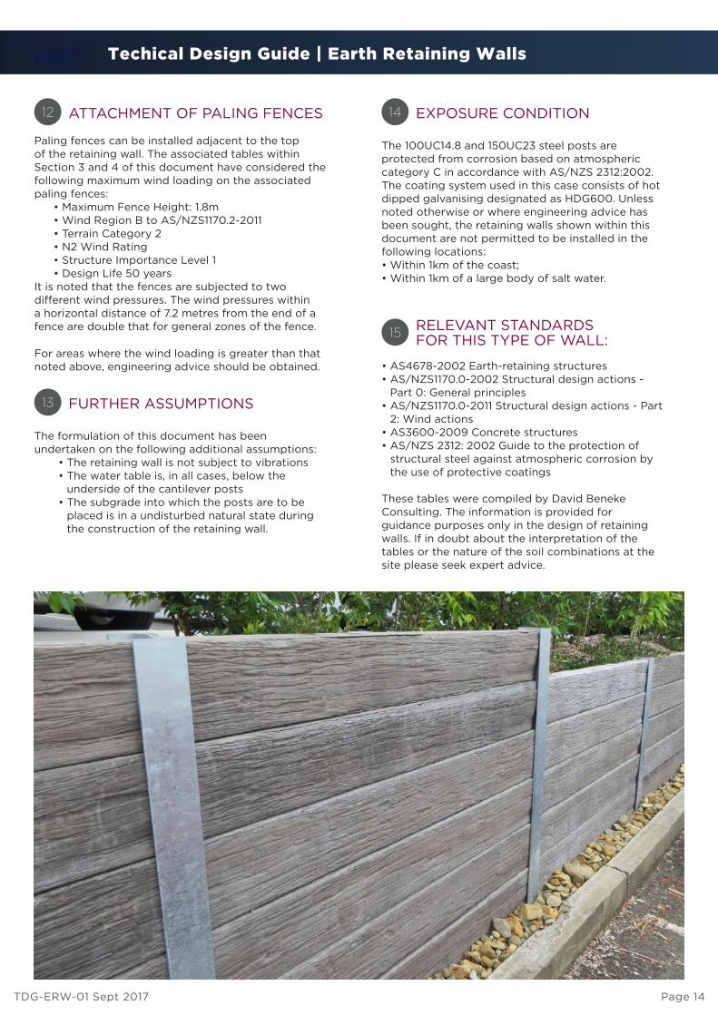
ATTACHMENT OF PALING FENCES
FURTHER ASSUMPTIONS
EXPOSURE CONDITION
RELEVANT STANDARDSFOR THIS TYPE OF WALL:
12
13
14
15
The formulation of this document has been undertaken on the following additional assumptions: • The retaining wall is not subject to vibrations • The water table is, in all cases, below the
underside of the cantilever posts • The subgrade into which the posts are to be
placed is in a undisturbed natural state during the construction of the retaining wall.
The 100UC14.8 and 150UC23 steel posts areprotected from corrosion based on atmosphericcategory C in accordance with AS/NZS 2312:2002.The coating system used in this case consists of hotdipped galvanising designated as HDG600. Unlessnoted otherwise or where engineering advice hasbeen sought, the retaining walls shown within thisdocument are not permitted to be installed in thefollowing locations:• Within 1km of the coast;• Within 1km of a large body of salt water.
• AS4678-2002 Earth-retaining structures• AS/NZS1170.0-2002 Structural design actions -
Part 0: General principles• AS/NZS1170.0-2011 Structural design actions - Part
2: Wind actions• AS3600-2009 Concrete structures• AS/NZS 2312: 2002 Guide to the protection of
structural steel against atmospheric corrosion by the use of protective coatings
These tables were compiled by David BenekeConsulting. The information is provided for guidance purposes only in the design of retaining walls. If in doubt about the interpretation of the tables or the nature of the soil combinations at the site please seek expert advice.
Paling fences can be installed adjacent to the top of the retaining wall. The associated tables within Section 3 and 4 of this document have considered the following maximum wind loading on the associated paling fences: • Maximum Fence Height: 1.8m • Wind Region B to AS/NZS1170.2-2011 • Terrain Category 2 • N2 Wind Rating • Structure Importance Level 1 • Design Life 50 years It is noted that the fences are subjected to two different wind pressures. The wind pressures within a horizontal distance of 7.2 metres from the end of a fence are double that for general zones of the fence.
For areas where the wind loading is greater than that noted above, engineering advice should be obtained.