Embed Size (px)
Citation preview

Page 1 of 28
Resysta – 6” and 4” Flat Board Siding
System Assembly Installation Guidelines
NOTE: Proper planning of the siding layout is essential for ease of installation of siding boards and siding components. Thoroughly read the following siding assembly instructions and obtain all necessary building permits prior to starting your installation. Decide finishing and trimming options prior to starting the project to ensure siding finishing detail is uniform for all sides of the building. Installation is the sole responsibility of the installer. Resysta Company assumes no responsibility whatsoever with respect to the installation. The information contained herein is provided for guidance purposes only and should not be relied upon as any absolute representation by Resysta.
Safety Tips: 1. Always check for power, gas, and water lines before installing. 2. Always wear safety glasses when operating power equipment.
Assembly Tips: 1. Battens should be flat and level to each other. Siding will follow the contour of the
wall. 2. Resysta siding system is not a rain screen or water proof system. Resysta siding is a
water shed system. 3. Proper wall preparation according to local building codes and wall covering
manufacture’s recommendations should be adhered to. This includes but is not limited to flashing all openings.
4. All holes should be predrilled and installation holes should be slotted. 5. Only use construction fastening material and hardware suitable for outdoor use (e.g.
stainless steel screws). 6. Always consider the linear expansion of Resysta, which is dependent on the
temperature but not the air humidity. See Table 1.2 “Resysta Expansion” for more information.
7. Cut-off pieces and/or abrasive dust must be disposed of separately. Please comply with regulations of your competent waste management. You may under no circumstances burn Resysta material.
8. Cutting to length should be carried out at consistent material temperature. Therefore, the material should be stored in the shade or in areas where it is not exposed to direct sunlight. The material can warm up considerably in the sun, leading to an increased change in length. In the case of more distinct fluctuations in material temperature, cutting to length may have to be adapted accordingly.
9. Please store Resysta products flat on level surface.

Page 2 of 28
Code Compliant Batten Spacing
Part
Number Part
Description Batten
Span (in) Minimum Steel
Gage Size
RESCP120612 Siding Board Flat 1/2” x 6” (0.530” x 6”) 16 20
RESCP120412 Siding Board Flat 1/2” x 4” (0.530” x 4”) 16 20
Table 1.1 "Batten Spacing Requirements"
Recommendation for Batten Spacing – If the siding is being installed in a hot southern location and will be exposed to direct sunlight for the majority of each day and/or the siding will be stained a dark color, the batten spacing is suggested be reduced to 8” or 12” center-to-center for all siding profiles.
Expansion / Contraction of Siding
Resysta Expansion – Contraction Guide Profile Length 12 ft Expansion / Contraction amount (approx.. 0.3% over 90 0F variation in temperature)
7/16” (0.432”)
Table 1.1 Expansion – Contraction: Average expected expansion – contraction (this can vary based on geographical region).
Resysta Siding Board Gap Guide
Trim Gap of Siding Boards H-Channel Gap Temperature at Installation Below 30 0F 60 0F 90 0F 120 0F
Amount for Siding Profile Length of 12 ft.
7/16” 5/16” 3/16” 0” 1/4”
Table 1.2 "Resysta Expansion" – Ensure a steady material temperature when cutting the boards to
size, i.e. the cutting has to be done under constant conditions, e.g. inside or in shade.
Always consider linear expansion of Resysta profiles during the installation of siding products. If temperatures fluctuate during the installation, the gaps placed between the ends of the boards and a corner, window, or door must change with the temperature. Use the guide above to gap boards during installation.

Page 3 of 28
Expansion – Contraction Tips:
1) Control Piece – at the start of the day cut a length of board that is desired to be installed and keep this board in the same area as the cutting and storage of the remaining boards. This board will be a “Control Piece” to reference when cutting other boards to be installed. Throughout the day the “Control Piece” can be referenced and the saw cuts adjusted accordingly as the boards expand and/or contract. Heat from the sun will cause Resysta boards to expand so if the material is stored in the shade keep the “Control Piece” in the shade as well.
Example: If 12ft boards are being installed put aside one 12ft board at the start of the day. Reference these boards throughout the day and adjust the cutting of the other boards to match
2) Control Gap – at the start of the installation place the siding gap according to Table 1.2 and mark the first gap made. This gap will be a “Control Gap” to reference when gapping the remaining boards to be installed. Throughout the installation reference back to this “Control Gap” to match the other gaps being installed. This will ensure that all the gaps installed are the same.

Page 4 of 28
Installation - Procedure
SECTION 1 – Batten Substructure
General Notes on Batten Substructure
Resysta siding boards can be installed in horizontal or vertical applications and the batten substructure should be planned to accommodate how the siding boards will be installed. Horizontal Siding / Vertical Battens Vertical Siding / Horizontal Battens
Resysta siding boards require a minimum of 6” from the ground to the start of the siding board in both horizontal and vertical installations. Plan the batten substructure and wall assembly accordingly to accommodate siding installation while adhering with local building code requirements.

Page 5 of 28
Wood Batten Substructure
Install the battens and secure to the frame substructure in compliance with local building codes. Ensure that the installed battens do not exceed the “Batten Spacing Requirements” of Table 1.1. On walls where two siding boards will be used end-to-end, a minimum of two battens must be used to accommodate the fastening of the siding boards and any trim pieces desired to the batten substructure where the boards meet. Prior to installing the Resysta siding boards, ensure that the batten installation provides a minimum ¾” air gap behind the siding boards and there is sufficient support for all siding boards and trim accessories. This is often achieved through the installation of battens with a minimum thickness of ¾”. Battens should be installed on top of a code compliant sheathing with fasteners and fastener spacing sufficient to accommodate all loads imposed upon it by the Resysta siding board, trim components, and any other accessories attached to the battens. Resysta siding boards must be attached to wood battens with #8 x 1-1/4” stainless steel screws taking care to not penetrate the weather barrier. If the weather barrier is going to be penetrated reference the weather barrier manufacture’s recommendations.
Aluminum Batten Substructure
Install the battens and secure to the frame substructure in compliance with local building codes. Ensure that the installed battens do not exceed the “Batten Spacing Requirements” of Table 1.1. On walls where two siding boards will be used end-to-end, a minimum of two battens must be used to accommodate the fastening of the siding boards and any trim pieces desired to the batten substructure where the boards meet. Prior to installing the Resysta siding boards, ensure that the batten installation provides a minimum ¾” air gap behind the siding boards and there is sufficient support for all siding boards and trim accessories. This is often achieved through the installation of battens with a minimum thickness of ¾” Battens should be installed on top of a code compliant sheathing with fasteners and fastener spacing sufficient to accommodate all loads imposed upon it by the Resysta siding board, trim components, and any other accessories attached to the battens. Resysta siding boards must be attached to aluminum battens with #8 x 3/4” TEC stainless steel screws taking care to not penetrate the weather barrier. If the weather barrier is going to be penetrated reference the weather barrier manufacture’s recommendations.
Notes on Screw Type to Install Resysta Siding Board
The screw should be a flat head or countersunk type to allow the screw head to sit into the screw channel on the siding board without interfering with the board being installed on top of it. The screw should have a partially unthreaded shank below the head. This will allow the board to move easily to accommodate expansion and contraction without the boards binding on the screw threads.

Page 6 of 28
SECTION 2 – Trim and Accessory Options
Aluminum Siding Trim systems made for Resysta siding boards are recommended for covering the ends and gaps of siding boards. Suggested supply includes, but is not limited to: Outside Corner Trim, Inside Corner Trim, Starter Strip (to start siding boards), H-Channel Trim (to cover wall gaps), J-Channel Trim (used for siding board termination). Aluminum Siding Trims are standard aluminum alloy 6063 T5 and have a .050” nominal wall thickness. Aluminum Siding Trims come in 10’ lengths and shall have a standard Mill Finish for field priming and painting unless otherwise specified.
Aluminum Siding Trim – General Installation Guidelines
Aluminum Siding Trim must be cut with a 150 tooth carbide-tip blade for nonferrous metal. Blade Lubricant must be applied to the blade before each cut and the lubricant should be cleaned from the trim prior to installation. None of Siding Trim should be installed horizontally unless weep holes are drilled at 8” intervals to allow for moisture to escape from behind the face flange. Exceptions to this are 1) Siding Starter Strip installed in any direction and 2) Siding J-Channel Trim when it is installed horizontally with its face flange pointing down.
Aluminum Siding Trim – Wood Batten Installation Guidelines
Aluminum Siding Trim must be pre-punched or drilled to receive the #8 x 5/8” wood screw for attaching them to wood furring strips. Trim should be fastened 16” on center for either horizontal or vertical installations. If the batten substructure spacing is reduced for the siding boards the trim should be fastened at the same interval as the siding. Be aware of fastener placement for the siding trims so as to not hinder the installation of the Resysta siding boards.
Depending on the type of wood battens used there is the possibility for the aluminum trim to go through the aluminum electrolysis effect. If this occurs, the aluminum trim could start to deteriorate. This is an extremely rare event that requires the correct conditions. However, if this is a concern it is recommended that a piece of felt be installed between the wood battens and the aluminum trim.
Aluminum Siding Trim – Aluminum Batten Installation Guidelines
When using metal battens, either steel or aluminum, it is recommended to use a #8 x 5/8” self-tapping fastener which can be driven through the aluminum siding trim and into the metal batten. Trim should be fastened 16” on center for either horizontal or vertical installations. If the batten substructure spacing is reduced for the siding boards the trim should be fastened at the same interval as the siding. Be aware of fastener placement for the siding trim so as to not hinder the installation of the Resysta siding boards.

Page 7 of 28
SECTION 3 – Horizontal Siding Applications
STEP 3.1 – Pre apply all finishing trim accessories such as trim around corners,
windows, and doors according to the pre plan layout and following the manufacture’s recommendations. Ensure that all trim is level and square. Battens should be installed vertically.
STEP 3.2 – Aluminum starter strip is required to install the Resysta siding board.
Attach the starter strip at the bottom of the battens following the fastener and spacing recommendations in Section 2. The Resysta siding boards will hang ½” below the bottom of the starter strip therefore the starter strip should be attached accordingly per the pre plan layout.
STEP 3.3 – Hook the groove end of the first siding board into the starter strip.
Page 8 of 28
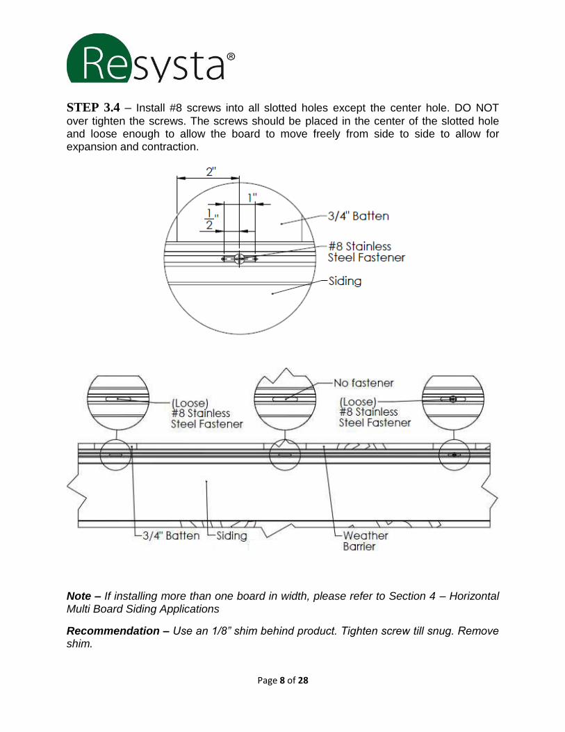
STEP 3.4 – Install #8 screws into all slotted holes except the center hole. DO NOT
over tighten the screws. The screws should be placed in the center of the slotted hole and loose enough to allow the board to move freely from side to side to allow for expansion and contraction.
Note – If installing more than one board in width, please refer to Section 4 – Horizontal Multi Board Siding Applications
Recommendation – Use an 1/8” shim behind product. Tighten screw till snug. Remove shim.

Page 9 of 28
STEP 3.5 – Install the final #8 screw snug in the slotted hole in the center of the board.
This will allow for expansion and contraction evenly to each side of the assembly.
STEP 3.6 – Hook the groove end of the next
board onto the tongue of the installed siding board.
STEP 3.7 – Continue installing siding boards
as outlined in Section 3 until siding is finished.

Page 10 of 28
SECTION 4 – Multi-Board Horizontal Siding Applications
2 Board Wide Installation without the H-Channel Trim (24ft max width)
STEPS 4.1.1 – Ensure that two battens have been installed where boards are to be
installed end to end.
STEP 4.1.2 – Follow Steps 3.1, 3.2, and 3.3 from Section 3 to install finishing trim,
starter strip, and hook in the 1st siding board.
STEP 4.1.3 – Install #8 screws into all slotted holes except the hole closest to the
abutted joint on both siding boards. DO NOT over tighten the screws. The screws should be placed in the center of the slotted hole and loose enough to allow the board to move freely from side to side to allow for expansion and contraction.
Page 11 of 28
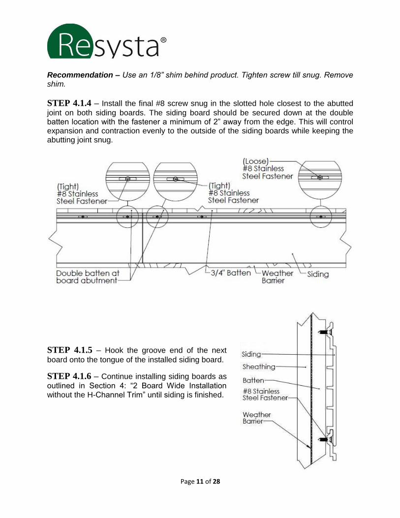
Recommendation – Use an 1/8” shim behind product. Tighten screw till snug. Remove shim.
STEP 4.1.4 – Install the final #8 screw snug in the slotted hole closest to the abutted
joint on both siding boards. The siding board should be secured down at the double batten location with the fastener a minimum of 2” away from the edge. This will control expansion and contraction evenly to the outside of the siding boards while keeping the abutting joint snug.
STEP 4.1.5 – Hook the groove end of the next
board onto the tongue of the installed siding board.
STEP 4.1.6 – Continue installing siding boards as
outlined in Section 4: “2 Board Wide Installation without the H-Channel Trim” until siding is finished.

Page 12 of 28
Multi-Board Wide Installation using Continuous H-Channel Trim
STEP 4.2.1 – Ensure that two battens have been installed where boards are to be
installed end to end.
STEP 4.2.2 – Follow Steps 3.1, 3.2, and 3.3 from Section 3 to install finishing trim,
starter strip, and hook in the 1st siding board. An H-Channel should be installed at each board abutment joint to cover the ends of the Resysta siding board. This is a option for installations using 3 or more boards abutted end-to-end.
STEP 4.2.3 – Install #8 screws into all
slotted holes except the center hole. DO NOT over tighten the screws. The screws should be placed in the center of the slotted hole and loose enough to allow the board to move freely from side to side to allow for expansion and contraction.

Page 13 of 28
STEP 4.2.4 – Install the final #8 screw snug in the slotted hole in the center of the
board. This will allow for expansion and contraction evenly to each side of the assembly.

Page 14 of 28
STEP 4.2.5 – Hook the groove end of the next board onto the tongue of the installed
siding board.
STEP 4.2.6 – Continue installing siding boards as outlined in Section 4: “Multi-Board
Wide Installation using the H-Channel Trim” until siding is finished.

Page 15 of 28
SECTION 5 – Vertical Siding Applications
STEP 5.1 – Pre apply all finishing trim accessories such as trim around corners,
windows, and doors according to the pre plan layout and following the manufacture’s recommendations. Ensure that all trim is level and square. Battens should be installed horizontally.
STEP 5.2 – A starter strip is required to install the Resysta siding board. Attach the
starter strip vertically at one end of the batten substructure following the fastener and spacing recommendations in Section 2. The Resysta siding boards will hang ½” beyond the starter strip therefore the starter strip should be attach accordingly per the pre plan layout. If the siding is starting in a corner the corner attachment and the starter strip should be attached at the same time.
STEP 5.3 – Hook the groove end of the first siding board into the starter strip.

Page 16 of 28
STEP 5.4 – Install a #8 screw into the slotted hole at the top of the siding board. DO
NOT over tighten this screw. This screw should be placed at the top of the slotted hole and loose enough to allow the board to move freely in the vertical direction allowing for expansion and contraction.
STEP 5.5 – Install #8 screws into the remaining slotted holes. DO NOT over tighten the
screws. These screws should be placed in the center of the slotted hole and loose enough to allow the board to move freely in the vertical direction allowing for expansion and contraction.
Special Requirement – By following these installation guides for vertical installation methods ALL expansion and contraction will happen at the bottom of the board. Gap the bottom of the board properly based on installation needs.
Note – If installing more than one board in height, please refer to Section 6 – Vertical Multi Board Siding Applications
Recommendation – Use an 1/8” shim behind product. Tighten screw till snug. Remove shim.
Page 17 of 28
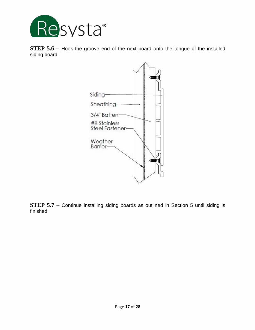
STEP 5.6 – Hook the groove end of the next board onto the tongue of the installed
siding board.
STEP 5.7 – Continue installing siding boards as outlined in Section 5 until siding is
finished.

Page 18 of 28
SECTION 6 – Multi-Board Vertical Siding Applications
2 Board High Installation without the H-Channel Trim (24ft max Height)
STEP 6.1.1 – Ensure that two battens have been installed where boards are to be
installed end to end.
STEP 6.1.2 – Follow Steps 5.1, 5.2, and 5.3 from Section 5 to install finishing trim,
starter strip, and hook in the 1st siding board.
STEP 6.1.3 – Install the bottom siding board first using a #8 screw into the slotted hole
at the top of the siding board. This screw should be placed at the top of the slotted hole and snug to the siding board to allow the board to move freely in the vertical direction allowing for expansion and contraction.
STEP 6.1.4 – Install #8 screws into the remaining slotted holes for the bottom siding
board. DO NOT over tighten the screws. These screws should be placed in the center of the slotted hole and loose enough to allow the board to move freely in the vertical direction allowing for expansion and contraction.

Page 19 of 28
STEP 6.1.5 – Install the top siding board by butting it against the bottom siding board
and securing a #8 screw into the slotted hole at the bottom of the siding board. This screw should be placed at the top of the slotted hole and snug to the siding board to allow the board to move freely in the vertical direction allowing for expansion and contraction.
STEP 6.1.6 – Install #8 screws into the remaining slotted holes for the top siding
board. DO NOT over tighten the screws. These screws should be placed in the center of the slotted hole and loose enough to allow the board to move freely in the vertical direction allowing for expansion and contraction.

Page 20 of 28
STEP 6.1.7 – Hook the groove end of the next board onto the tongue of the installed
siding board.
STEP 6.1.8 – Continue installing siding boards as outlined in Section 6: “2 Board High
Installation without the H-Channel Trim” until siding is finished.

Page 21 of 28
Multi-Board High Installation using the Continuous H-Channel Trim
STEP 6.2.1 – Ensure that two battens have been installed where boards are to be
installed end to end.
STEP 6.2.2 – Follow Steps 5.1, 5.2, and 5.3 from Section 5 to install finishing trim,
starter strip, and hook in the 1st siding board. An H-Channel should be installed at each board abutment joint to cover the ends of the Resysta siding board. This is an option for installations using 3 or more boards abutted end-to-end. None of Siding Trim should be installed horizontally unless weep holes are drilled at 8” intervals to allow for moisture to escape from behind the face flange.
STEP 6.2.3 – Install a #8 screw into the slotted hole at the top of the siding board. DO
NOT over tighten this screw. This screw should be placed at the top of the slotted hole and loose enough to allow the board to move freely in the vertical direction allowing for expansion and contraction.

Page 22 of 28
STEP 6.2.4 – Install #8 screws into the remaining slotted holes. DO NOT over tighten
the screws. These screws should be placed in the center of the slotted hole and loose enough to allow the board to move freely in the vertical direction allowing for expansion and contraction.
STEP 6.2.5 – Hook the groove end of the next board onto the tongue of the installed
siding board. Proper gapping between the siding boards and H-Channel is necessary.

Page 23 of 28
SECTION 7 – Air Barrier – Requirements
For all of the installation options it is crucial to allow the uninterrupted flow of air from
the bottom to the top of the wall system. This creates a chimney effect which provides
not only moisture wicking but also cooling behind the Resysta siding.
Air flow must be able to release at the top of the construction. For that reason a ½” gap
between the top of the Resysta siding board and the Parapet Wall Cap Flashing is
necessary. The same size gap is needed between the face of the Resysta siding board
and the Parapet Wall Cap Flashing. This should also be followed when using the J
channel at the top of the wall.

Page 24 of 28
SECTION 8 – Finishing Trim
HORIZONTAL OUTSIDE CORNERS – Outside corner trim should be pre
applied prior to installing siding boards. The starter strip for the first board should be installed butted against the corner trim, not overlapping the corner trim attachment flange. The siding board end that is inserted into the outside corner should be miter cut at a 45 degree angle to match up with the outside corner internal web. Follow the gap guide when installing the siding board to allow for expansion and contraction within the outside corner trim. Install horizontal siding per previous sections. When using aluminum hat channel for outside corner application, installer may reverse and attaché hat channel so that the flanges meet.

Page 25 of 28
HORIZONTAL INSIDE CORNERS – Inside corner trim should be pre-applied
prior to installing siding boards. The starter strip for the first board should be installed butted against the corner trim, not overlapping the corner trim attachment flange. Follow the gap guide when installing the siding board to allow for expansion and contraction within the inside corner trim. Install horizontal siding per previous sections. Note – The corners of the Resysta siding inside of the trim need to be mitered. This gives more room for expansion inside of the trim and leaves more of the face of the siding when it contracts.

Page 26 of 28
VERTICAL OUTSIDE CORNERS – Outside corner trim should be pre-applied
prior to installing siding boards. The starter strip for the first board should be installed inside the flange of the outside corner. Both the outside corner and the starter strip can be attached together using the same fasteners. Install the vertical siding boards per previous sections. When using aluminum hat channel for outside corner application, installer may reverse and attaché hat channel so that the flanges meet. .
VERTICAL INSIDE CORNERS – Inside corner trim should be pre-applied prior to
installing siding boards. The starter strip for the first board should be installed inside the flange of the inside corner. Both the inside corner and the starter strip can be attached together using the same fasteners. Install the vertical siding boards per previous sections.

Page 27 of 28
BOARD TERMINATION TRIM – When a siding board in either a horizontal or
vertical application terminates into a wall, eave, window, door etc. a J-channel should be used to cover the exposed end of the siding board. The J-channel should also be used along the bottom of a vertical installation. J-channel trim should be pre-applied prior to installing siding boards. In the case of an intersecting joint the starter strip should be installed butted against the J-channel trim, not overlapping the J-channel trim attachment flange. Follow the gap guide when installing the siding board to allow for expansion and contraction within the J-channel trim. HORIZONTAL APPLICATION
VERTICAL APPLICATION Requirement – When the J-Channel is installed in a horizontal position weep holes must be drilled at 8” intervals to allow for moisture to escape from behind the face flange. Do not drill weep holes over a door or window installation.

Page 28 of 28
SECTION 9 – Stain and Sealant System Resysta recommends using approved water based stain and sealant system.
Safety Warning Resysta® Products do not present an inhalation, ingestion, or contact health hazard unless subjected to operations such as sawing, sanding, or machining which result in the generation of airborne particulate. This product contains crystalline silica. Respirable crystalline silica limits are specified by OSHA. Exposure to respirable (fine) silica dust depends on a variety of factors, including activity rate (e.g. cutting rate), method of handling, ventilation, environmental conditions (e.g. weather conditions, workstation orientation), and engineering control measures used. Exposures to respirable crystalline silica above limits established by OSHA are not expected during the normal use of this product. Crystalline silica, has been shown to cause silicosis, and has been identified by the State of California, IARC and NTP as a known human carcinogen. The risk of developing silicosis is dependent upon the exposure intensity and duration. It is recommended that a NIOSH approved particulate respirator be worn whenever working with this product results in airborne dust exposure.
Please direct product inquiries to:
Resysta North America, Inc.
4035 Cheyenne Ct.
Chino, CA. 91710
Tel: 909-393-2888
Email: [email protected]