Embed Size (px)
Citation preview
RE
ST
RIC
TE
D
Sou
rce of C
an
adia
n Civil A
eron
autica
l Data
: © 20
14 N
AV
CA
NA
DA
All righ
ts reserve
d
E
RE
ST
RIC
TE
D
35
SYMBOL LEGEND
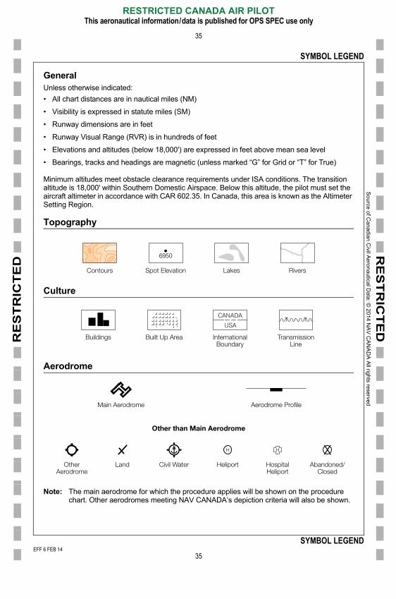
GeneralUnless otherwise indicated:
• All chart distances are in nautical miles (NM)
• Visibility is expressed in statute miles (SM)
• Runway dimensions are in feet
• Runway Visual Range (RVR) is in hundreds of feet
• Elevations and altitudes (below 18,000') are expressed in feet above mean sea level
• Bearings, tracks and headings are magnetic (unless marked “G” for Grid or “T” for True)
Minimum altitudes meet obstacle clearance requirements under ISA conditions. The transition altitude is 18,000' within Southern Domestic Airspace. Below this altitude, the pilot must set the aircraft altimeter in accordance with CAR 602.35. In Canada, this area is known as the Altimeter Setting Region.
Topography
Culture
Aerodrome
Contours Spot Elevation Lakes Rivers
Buildings Built Up Area InternationalBoundary
TransmissionLine
Main Aerodrome Aerodrome Profile
Other than Main Aerodrome
EFF 6 FEB 14
RESTRICTED CANADA AIR PILOTThis aeronautical information/data is published for OPS SPEC use only
35
SYMBOL LEGEND
Note: The main aerodrome for which the procedure applies will be shown on the procedure chart. Other aerodromes meeting NAV CANADA’s depiction criteria will also be shown.
LandOtherAerodrome
Civil Water Heliport HospitalHeliport
Abandoned/Closed
001/2014
FF 6 FEB 14
So
urce o
f Ca
nad
ian C
ivil Ae
rona
utical D
ata: ©
201
4 NA
V C
AN
AD
A A
ll rights rese
rved
E
RE
ST
RIC
TE
DR
ES
TR
ICT
ED
SYMBOL LEGEND
36
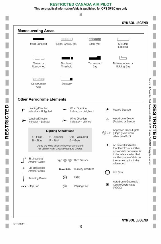
Manoeuvering Areas
Other Aerodrome Elements
Hard Surfaced
Closed orAbandoned
ConstructionArea
Stopway
DisplacedThreshold
TurnaroundBay
Taxiway, Apron orHolding Bay
Sand, Gravel, etc. Steel Mat Ski Strip(Labelled)
Landing DirectionIndicator – Unlighted
Bi-directionalArrester Cable RVR Sensor
Runway Gradient
FATO
Parking Pad
Uni-directionalArrester Cable
Arresting Barrier
Stop Bar
Lights are white unless otherwise annotated.For use on Night Circuit Procedure Charts.
Lighting Annotations
Wind DirectionIndicator – Unlighted
Hazard Beacon
An asterisk indicatesthat the CFS or anotherappropriate document isto be referenced or thatanother piece of data onthe same chart is to bereferenced
Hot Spot
Aerodrome Beacon(Rotating or Strobe)
Aerodrome GeometricCentre Coordinates
Approach Slope Lights(Slope given whenother than 3.0°)
Landing DirectionIndicator – Lighted
F – FixedB – Blue
Fl – FlashingR – Red
Occ – OccultingG – Green
Wind DirectionIndicator – Lighted
EFF 6 FEB 14
RESTRICTED CANADA AIR PILOTThis aeronautical information/data is published for OPS SPEC use only
36
SYMBOL LEGEND
(AGCC)
001/2014
FF 6 FEB 14
So
urce o
f Ca
nad
ian C
ivil Ae
rona
utical D
ata: ©
201
4 NA
V C
AN
AD
A A
ll rights rese
rved
E
RE
ST
RIC
TE
DR
ES
TR
ICT
ED
SYMBOL LEGEND
37
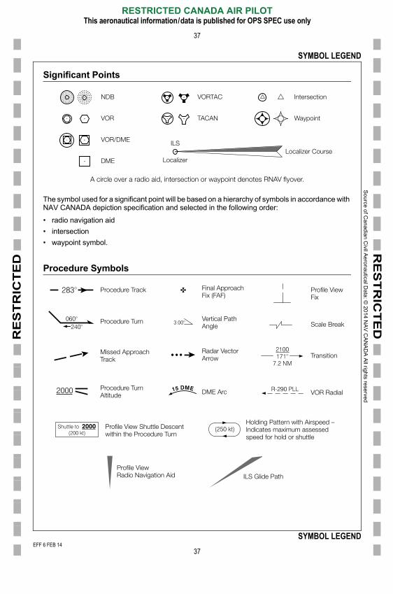
Significant Points
The symbol used for a significant point will be based on a hierarchy of symbols in accordance with NAV CANADA depiction specification and selected in the following order:
• radio navigation aid
• intersection
• waypoint symbol.
Procedure Symbols
Intersection
A circle over a radio aid, intersection or waypoint denotes RNAV flyover.
VORTACNDB
VOR
VOR/DME
DME
TACAN
ILS
LocalizerLocalizer Course
Waypoint
Procedure Track
Procedure Turn
Missed ApproachTrack
Final ApproachFix (FAF)
Profile ViewFix
Transition
Scale BreakVertical PathAngle
Radar VectorArrow
Procedure TurnAltitude
Profile View Shuttle Descentwithin the Procedure Turn
VOR RadialDME Arc
Holding Pattern with Airspeed –Indicates maximum assessedspeed for hold or shuttle
EFF 6 FEB 14
RESTRICTED CANADA AIR PILOTThis aeronautical information/data is published for OPS SPEC use only
37
SYMBOL LEGEND
ILS Glide PathProfile ViewRadio Navigation Aid
001/2014
FF 6 FEB 14
So
urce o
f Ca
nad
ian C
ivil Ae
rona
utical D
ata: ©
201
4 NA
V C
AN
AD
A A
ll rights rese
rved
E
RE
ST
RIC
TE
DR
ES
TR
ICT
ED
SYMBOL LEGEND
38
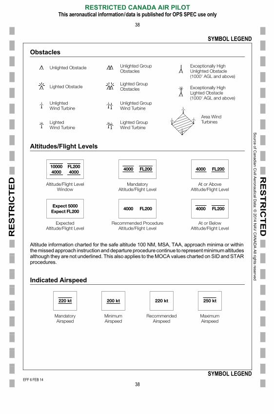
Obstacles
Altitudes/Flight Levels
Altitude information charted for the safe altitude 100 NM, MSA, TAA, approach minima or within the missed approach instruction and departure procedure continue to represent minimum altitudes although they are not underlined. This also applies to the MOCA values charted on SID and STAR procedures.
Indicated Airspeed
Unlighted Obstacle Unlighted GroupObstacles
Lighted GroupObstacles
Unlighted GroupWind Turbine
Lighted GroupWind Turbine
Area WindTurbines
Exceptionally HighUnlighted Obstacle(1000' AGL and above)
Exceptionally HighLighted Obstacle(1000' AGL and above)
Lighted Obstacle
UnlightedWind Turbine
LightedWind Turbine
Altitude/Flight LevelWindow
ExpectedAltitude/Flight Level
MandatoryAltitude/Flight Level
Recommended ProcedureAltitude/Flight Level
At or AboveAltitude/Flight Level
At or BelowAltitude/Flight Level
100004000
Expect 5000Expect FL200
FL2004000
4000 FL200 4000 FL200
4000 FL2004000 FL200
Mandatory Minimum Recommended Maximum
220 kt 250 kt220 kt 200 kt
EFF 6 FEB 14
RESTRICTED CANADA AIR PILOTThis aeronautical information/data is published for OPS SPEC use only
38
SYMBOL LEGEND
Airspeed Airspeed Airspeed Airspeed
001/2014
FF 6 FEB 14
So
urce o
f Ca
nad
ian C
ivil Ae
rona
utical D
ata: ©
201
4 NA
V C
AN
AD
A A
ll rights rese
rved
EEF
RE
ST
RIC
TE
DR
ES
TR
ICT
ED
SYMBOL LEGEND
39
Airspace Restrictions
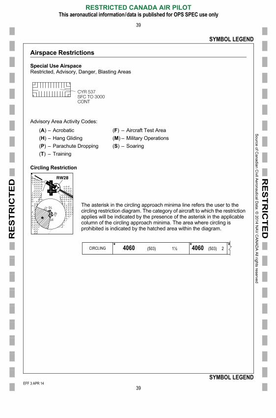
Special Use AirspaceRestricted, Advisory, Danger, Blasting Areas
Advisory Area Activity Codes:
(A) – Acrobatic (F) – Aircraft Test Area
(H) – Hang Gliding (M) – Military Operations
(P) – Parachute Dropping (S) – Soaring
(T) – Training
Circling Restriction
The asterisk in the circling approach minima line refers the user to the circling restriction diagram. The category of aircraft to which the restriction applies will be indicated by the presence of the asterisk in the applicable column of the circling approach minima. The area where circling is prohibited is indicated by the hatched area within the diagram.
CYR 537SFC TO 3000CONT
CIRCLING * 4060 (503) 1½ *4060 (503) 2 *
EFF 3 APR 14
RESTRICTED CANADA AIR PILOTThis aeronautical information/data is published for OPS SPEC use only
39
SYMBOL LEGENDFF 3 APR 14
F 6 FEB 14

So
urce o
f Ca
nad
ian C
ivil Ae
rona
utical D
ata: ©
201
4 NA
V C
AN
AD
A A
ll rights rese
rved
E
RE
ST
RIC
TE
DR
ES
TR
ICT
ED
SYMBOL LEGEND
40
Magnetic Variation
Magnetic variation changes over time. The magnetic variation depicted on an instrument procedure represents the magnetic variation used in determining the procedure’s magnetic bearings, tracks and radials on the chart. The magnetic variation used within aircraft avionics may be updated on a different cycle and could result in the on board avionic system displaying slightly different magnetic tracks from the charted values.
VAR 15°W
SDA
VAR N/A
NDA
SDA & NDA
SDA & NDASDA NDA
Instrument ApproachProcedures
SID, STAR and DepartureProcedures
Visual Approach Charts
Night Circuit Procedures
Aerodrome/Heliport Charts
Taxi Charts
Parking Area and De-icing Positions and Procedure Charts
Operations in the Absence of Apron Control Charts
Start Boxes Charts
EFF 6 FEB 14
RESTRICTED CANADA AIR PILOTThis aeronautical information/data is published for OPS SPEC use only
40
SYMBOL LEGEND
001/2014
FF 6 FEB 14
RE
ST
RIC
TE
D
Sou
rce of C
an
adia
n Civil A
eron
autica
l Data
: © 20
14 N
AV
CA
NA
DA
All righ
ts reserve
d
E
RE
ST
RIC
TE
D
41
INSTRUMENT APPROACH PROCEDURES
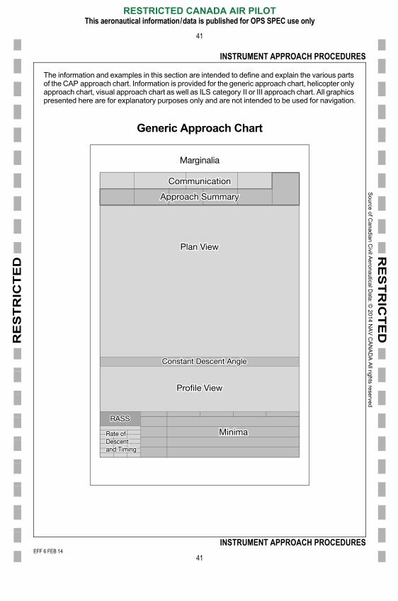
The information and examples in this section are intended to define and explain the various parts of the CAP approach chart. Information is provided for the generic approach chart, helicopter only approach chart, visual approach chart as well as ILS category II or III approach chart. All graphics presented here are for explanatory purposes only and are not intended to be used for navigation.
Generic Approach Chart
Marginalia
Profile View
RASS
Rate ofDescentand Timing
Plan View
Approach Summary
Communication
Minima
Constant Descent Angle
EFF 6 FEB 14
RESTRICTED CANADA AIR PILOTThis aeronautical information/data is published for OPS SPEC use only
41
INSTRUMENT APPROACH PROCEDURES
001/2014
FF 6 FEB 14

So
urce o
f Ca
nad
ian C
ivil Ae
rona
utical D
ata: ©
201
4 NA
V C
AN
AD
A A
ll rights rese
rved
E
RE
ST
RIC
TE
DR
ES
TR
ICT
ED
INSTRUMENT APPROACH PROCEDURES
42
Marginalia
Information shown in the periphery of the approach chart includes the procedure identification, AGCC, primary variation or declination used in determining the procedure’s bearings, tracks or radials, aerodrome identification, procedure effective date and chart number.
Procedure IdentificationBasic NamingThe procedure identification is the name used to uniquely identify the procedure at an aerodrome. The first part of the procedure identification indicates the primary navigation type required for final approach lateral guidance.
• NDB → “NDB”• VOR or VORTAC → “VOR”• Localizer → “LOC”• Localizer Back Course → “LOC (BC)”• ILS → “ILS”• ILS Category II/III → “ILS CAT II or III”• RNAV GNSS → “RNAV (GNSS)”• RNAV RNP → “RNAV (RNP)”
The runway number follows the navigation type when the approach procedure provides minima
CYHZ-IAP-2AHALIFAX/STANFIELD INTL, NS
ILS RWY 14 445247N 0633037W VAR 19°W CYHZATIS � 121.0 CTR � 119.2 TWR � 118.4 236.6 GND � 121.9 275.8
CYHZ-IAP-2A
110 580130 690150 800
ILS RWY 14 CYHZEFF 18 OCT 12
Volume Bar
Procedure Identification
Chart Number
Aerodrome Name
Province/Territory
Aerodrome Identifier
AGCC
Magnetic Variation
Effective Date
EFF 6 FEB 14
RESTRICTED CANADA AIR PILOTThis aeronautical information/data is published for OPS SPEC use only
42
INSTRUMENT APPROACH PROCEDURES
for a straight-in approach.
• VOR RWY 26• RNAV (GNSS) RWY 14
001/2014
FF 6 FEB 14
So
urce o
f Ca
nad
ian C
ivil Ae
rona
utical D
ata: ©
201
4 NA
V C
AN
AD
A A
ll rights rese
rved
E
RE
ST
RIC
TE
DR
ES
TR
ICT
ED
INSTRUMENT APPROACH PROCEDURES
43
Additional Navigation RequirementsWhen all minima lines of a VOR or NDB type approach chart also require the use of DME equipment to identify fixes within the final segment, the procedure identification includes “/DME”.
• VOR/DME RWY 13• NDB/DME RWY 35
In all other cases, additional navigation requirements are indicated within the minima lines of the approach:
• ILS/DME• LOC/DME• LNAV/VNAV• LPV
Pilots must determine in advance that the approach and missed approach can be accomplished utilizing the navigation equipment on board their particular aircraft.
Multiple ProceduresWhen a single chart is used to show two approach procedures, the procedure identification separates the navigation types using the term “or”. ILS and LOC procedures are considered one approach for this purpose and are not separately identified.
• ILS or NDB RWY 25
Duplicate ProceduresAvionics database coding standards identify 8 navigation types applicable to straight-in procedure identifications. They are:
• ILS• LOC• LOC(BC)• VOR• VOR/DME• NDB• NDB/DME• RNAV
Two approach procedures to the same runway requiring the use of the same navigation type indicator are considered duplicate procedures for database coding purposes. To uniquely identify these procedures, an alpha character starting with “Z” and proceeding backwards through the alphabet (Z, Y, X…) is added to the procedure identification between the navigation type and runway number. The procedure assigned the “Z” character is considered the predominant procedure and will be the only retrievable procedure in avionics databases having limited storage capabilities.
• RNAV (GNSS) Z RWY 26
EFF 6 FEB 14
RESTRICTED CANADA AIR PILOTThis aeronautical information/data is published for OPS SPEC use only
43
INSTRUMENT APPROACH PROCEDURES
• RNAV (RNP) Y RWY 26
• VOR Z RWY 13• VOR Y RWY 13
001/2014
FF 6 FEB 14

So
urce o
f Ca
nad
ian C
ivil Ae
rona
utical D
ata: ©
201
4 NA
V C
AN
AD
A A
ll rights rese
rved
E
RE
ST
RIC
TE
DR
ES
TR
ICT
ED
INSTRUMENT APPROACH PROCEDURES
44
Circling Only ProceduresApproach procedures providing only circling minima are not identified as associated to a specific runway. Instead, these procedures are identified using an alpha character after the navigation type starting with “A” and proceeding forward through the alphabet (A, B, C…). The next sequential alpha character is assigned to the next circling only procedure for the site based on its order within the Canadian instrument procedure inventory.
• RNAV (GNSS) A• NDB B
Additional SuffixesThe procedure identification may be suffixed with one or a combination of the following three suffixes.
• “(TRUE)” Identifies the procedure as existing in NDA
• “(GNSS)” Identifies a VOR or NDB type procedure as a GNSS overlay
• “(DND)” Identifies the procedure as a procedure designed and maintained by theDepartment of National Defence.
Chart NumberingWithin the entire inventory of effective Canadian instrument procedures, procedure charts are sequenced according to NAV CANADA specifications. Chart numbers are then assigned to each chart based on the established sequence. The sequencing is done considering the entire inventory of procedures and is not applied within the isolation of one specific paper product (CAP, RCAP or GPH 200 volume). For this reason, some chart numbers may appear to be missing when observed within the isolation of one specific paper product.
Page numbers are assigned to a chart as explained here. Items 3 and 4 will only be used when they are required.
Item Item 1 is the four letter identification of the specific aerodrome or heliport site.
Item Item 2 is expressed as one of eleven abbreviations representing the procedure chart type. They include:
STAR Standard Terminal Arrival Chart AD Aerodrome Chart
IAP Instrument Approach Procedure Chart HP Heliport Chart
CYKF-IAP-3C
EFF 6 FEB 14
RESTRICTED CANADA AIR PILOTThis aeronautical information/data is published for OPS SPEC use only
44
INSTRUMENT APPROACH PROCEDURES
VAP Visual Approach Procedure Chart GM Ground Movement/Taxi Chart
SID Standard Instrument Departure Chart APD Aircraft Parking/Docking Chart
DP Departure Procedure Chart NCP Night Circuit Procedure Chart
NOR Noise Operating Restrictions/Noise Abatement Procedure Chart
001/2014
FF 6 FEB 14

So
urce o
f Ca
nad
ian C
ivil Ae
rona
utical D
ata: ©
201
4 NA
V C
AN
AD
A A
ll rights rese
rved
E
RE
ST
RIC
TE
DR
ES
TR
ICT
ED
INSTRUMENT APPROACH PROCEDURES
45
Item Item 3 is a one or two digit number. For STAR, VAP, SID and DP charts the number is assigned sequentially based on the procedure. A subsequent number is not assigned to the additional chart pages of a multi-page instrument procedure. These instances are accounted for using item 4 explained below.
For NOR, AD, HP and APD charts the number is assigned sequentially for each subsequent page.
For IAP charts, the item 3 number is assigned based on the type of IAP as follows:
For GM charts, the item 3 number is assigned based on the type of GM chart as follows:
Item Item 4 is expressed as an alpha character starting with “A” and proceeding forward through the alphabet. It is assigned sequentially to each chart page that is not already uniquely numbered.
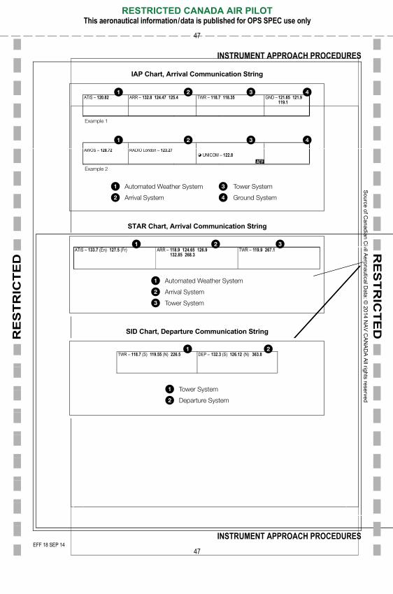
Communication
Under standard conditions, communication information is presented on a procedure chart using a series of communication systems as explained here.
The five communication systems are defined as follows:
Automated Weather System: Pre-recorded or voice generated weather or site operations information. Applicable communication agencies include ATIS, AWOS and LWIS.
Arrival System: Communication information pertaining to the most common method upon which a pilot would receive arrival instructions and/or approach clearance in low level controlled airspace within 30 NM of the aerodrome site. Applicable agencies include CTR, ARR, TML, RADIO and PAR.
Tower System: Communication information pertaining to aircraft movement (airborne and runway) around the aerodrome site. Applicable agencies include tower (TWR), RADIO, UNICOM, airport radio (APRT RADIO) and traffic (TFC).
1 Precision Approach Radar 6 VOR
2 ILS CAT I, II, III 7 TACAN
3 RNAV 8 NDB/DME
4 LOC or LOC (BC) 9 NDB
5 VOR/DME
1 Taxi Chart 3 Low Visibility Taxi Route Chart
2 Standard Taxi Route Chart 4 De-icing Chart
EFF 6 FEB 14
RESTRICTED CANADA AIR PILOTThis aeronautical information/data is published for OPS SPEC use only
45
INSTRUMENT APPROACH PROCEDURES
Ground System: Communication information pertaining to aircraft movement (taxiways and aprons) on the aerodrome site. When the agency identified in the tower system also provides the ground system service, it is not restated here. When an aerodrome site uses a clearance delivery service, it is stated as part of the ground system. Applicable agencies include clearance delivery (CLNC DEL), APRON, ground (GND), pad control (PAD CTL) and ICEMAN.
001/2014
FF 6 FEB 14
So
urce o
f Ca
nad
ian C
ivil Ae
rona
utical D
ata: ©
201
4 NA
V C
AN
AD
A A
ll rights rese
rved
E
RE
ST
RIC
TE
DR
ES
TR
ICT
ED
INSTRUMENT APPROACH PROCEDURES
46
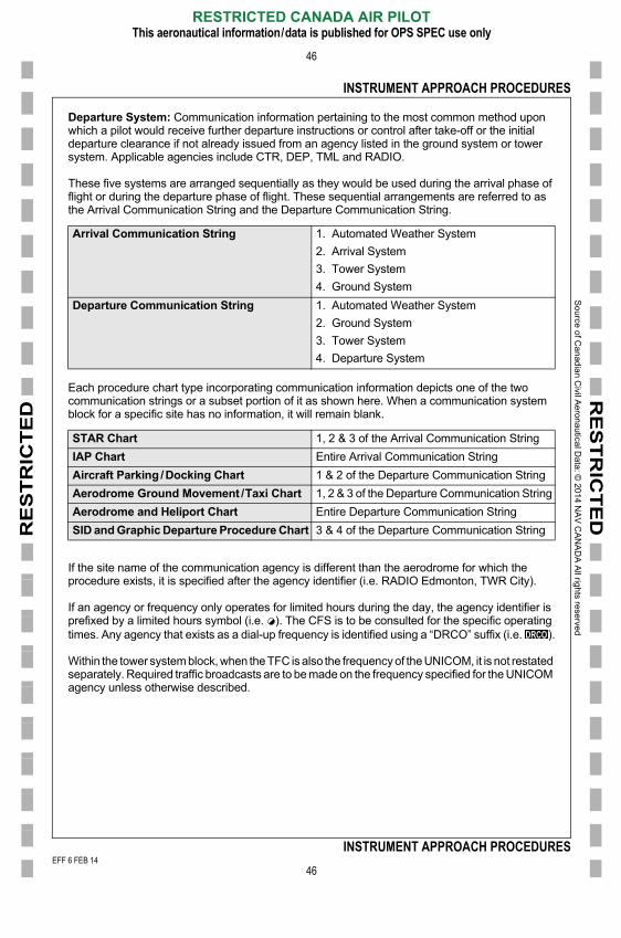
Departure System: Communication information pertaining to the most common method upon which a pilot would receive further departure instructions or control after take-off or the initial departure clearance if not already issued from an agency listed in the ground system or tower system. Applicable agencies include CTR, DEP, TML and RADIO.
These five systems are arranged sequentially as they would be used during the arrival phase of flight or during the departure phase of flight. These sequential arrangements are referred to as the Arrival Communication String and the Departure Communication String.
Each procedure chart type incorporating communication information depicts one of the two communication strings or a subset portion of it as shown here. When a communication system block for a specific site has no information, it will remain blank.
If the site name of the communication agency is different than the aerodrome for which the procedure exists, it is specified after the agency identifier (i.e. RADIO Edmonton, TWR City).
If an agency or frequency only operates for limited hours during the day, the agency identifier is prefixed by a limited hours symbol (i.e. ). The CFS is to be consulted for the specific operating times. Any agency that exists as a dial-up frequency is identified using a “DRCO” suffix (i.e. ).
Within the tower system block, when the TFC is also the frequency of the UNICOM, it is not restated separately. Required traffic broadcasts are to be made on the frequency specified for the UNICOM agency unless otherwise described.
Arrival Communication String 1. Automated Weather System
2. Arrival System
3. Tower System
4. Ground System
Departure Communication String 1. Automated Weather System
2. Ground System
3. Tower System
4. Departure System
STAR Chart 1, 2 & 3 of the Arrival Communication String
IAP Chart Entire Arrival Communication String
Aircraft Parking /Docking Chart 1 & 2 of the Departure Communication String
Aerodrome Ground Movement /Taxi Chart 1, 2 & 3 of the Departure Communication String
Aerodrome and Heliport Chart Entire Departure Communication String
SID and Graphic Departure Procedure Chart 3 & 4 of the Departure Communication String
EFF 6 FEB 14
RESTRICTED CANADA AIR PILOTThis aeronautical information/data is published for OPS SPEC use only
46
INSTRUMENT APPROACH PROCEDURES
001/2014
FF 6 FEB 14
So
urce o
f Ca
nad
ian C
ivil Ae
rona
utical D
ata: ©
201
4 NA
V C
AN
AD
A A
ll rights rese
rved
EEF
RE
ST
RIC
TE
DR
ES
TR
ICT
ED
INSTRUMENT APPROACH PROCEDURES
47
IAP Chart, Arrival Communication String
STAR Chart, Arrival Communication String
SID Chart, Departure Communication String
ATIS � 120.82 ARR � 132.8 124.47 125.4 TWR � 118.7 118.35 GND � 121.65 121.9119.1
AWOS � RADIO London � UNICOM �
Automated Weather System
Arrival System
Example 1
Example 2
Tower System
Ground System
TWR � 119.9 267.1ARR � 118.9 124.65 126.9132.85 268.3
ATIS � 133.7 (En) 127.5 (Fr)
Automated Weather System
Arrival System
Tower System
DEP � 132.3 (S) 126.12 (N) 363.8TWR � 118.7 (S) 119.55 (N) 226.5
Tower System
Departure System
EFF 18 SEP 14
RESTRICTED CANADA AIR PILOTThis aeronautical information/data is published for OPS SPEC use only
47
INSTRUMENT APPROACH PROCEDURESFF 18 SEP 14
F 6 FEB 14

So
urce o
f Ca
nad
ian C
ivil Ae
rona
utical D
ata: ©
201
4 NA
V C
AN
AD
A A
ll rights rese
rved
E
RE
ST
RIC
TE
DR
ES
TR
ICT
ED
INSTRUMENT APPROACH PROCEDURES
48
ATF & MF IndicationAerodrome sites having either an ATF area or an MF area around them are identified by charting the appropriate symbol in the bottom right corner of the Tower System block. The ATF and MF symbol may be complimented with other symbols to further define the specific details of the ATF or MF area. The possible symbols are explained here:
Tower System Examples
Indicates the presence of an ATF area with standard dimensions (5 NM, 3000' AAE, [±100']) around the aerodrome site.
Indicates the presence of an MF area with standard dimensions (5 NM, 3000' AAE, [±100']) around the aerodrome site.
Indicates that the ATF or MF area exists for only a portion of the day.
Indicates that the ATF or MF area is non-standard. Non-standard is deemed to exist if the area is not 5 NM in radius and 3000' AAE (±100'). In these cases, the CFS is to be consulted for further information.
When a four letter aerodrome identification follows the ATF or MF symbol, this indicates that the ATF or MF area is centred on an adjacent site. The adjacent site is identified by the four letter identifier.
ATF CYGQMF CYAW
RADIO � 122.2UNICOM � 122.8
ATF CYGQ
TWR � 119.7 119.1 239.6RADIO Kamloops � 119.7
EFF 6 FEB 14
RESTRICTED CANADA AIR PILOTThis aeronautical information/data is published for OPS SPEC use only
48
INSTRUMENT APPROACH PROCEDURES
001/2014
FF 6 FEB 14
So
urce o
f Ca
nad
ian C
ivil Ae
rona
utical D
ata: ©
201
4 NA
V C
AN
AD
A A
ll rights rese
rved
E
RE
ST
RIC
TE
DR
ES
TR
ICT
ED
INSTRUMENT APPROACH PROCEDURES
49
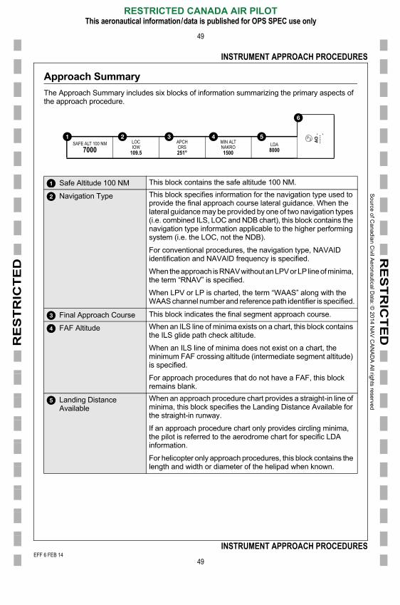
Approach Summary
The Approach Summary includes six blocks of information summarizing the primary aspects of the approach procedure.
Safe Altitude 100 NM This block contains the safe altitude 100 NM.
Navigation Type This block specifies information for the navigation type used to provide the final approach course lateral guidance. When the lateral guidance may be provided by one of two navigation types (i.e. combined ILS, LOC and NDB chart), this block contains the navigation type information applicable to the higher performing system (i.e. the LOC, not the NDB).
For conventional procedures, the navigation type, NAVAID identification and NAVAID frequency is specified.
When the approach is RNAV without an LPV or LP line of minima, the term “RNAV” is specified.
When LPV or LP is charted, the term “WAAS” along with the WAAS channel number and reference path identifier is specified.
Final Approach Course This block indicates the final segment approach course.
FAF Altitude When an ILS line of minima exists on a chart, this block contains the ILS glide path check altitude.
When an ILS line of minima does not exist on a chart, the minimum FAF crossing altitude (intermediate segment altitude) is specified.
For approach procedures that do not have a FAF, this block remains blank.
Landing DistanceAvailable
When an approach procedure chart provides a straight-in line of minima, this block specifies the Landing Distance Available for the straight-in runway.
If an approach procedure chart only provides circling minima, the pilot is referred to the aerodrome chart for specific LDA information.
For helicopter only approach procedures, this block contains the
SAFE ALT 100 NM7000
LOCIOW
109.5
APCHCRS251°
MIN ALTNAKRO1500
LDA8000
EFF 6 FEB 14
RESTRICTED CANADA AIR PILOTThis aeronautical information/data is published for OPS SPEC use only
49
INSTRUMENT APPROACH PROCEDURES
length and width or diameter of the helipad when known.
001/2014
FF 6 FEB 14
So
urce o
f Ca
nad
ian C
ivil Ae
rona
utical D
ata: ©
201
4 NA
V C
AN
AD
A A
ll rights rese
rved
E
RE
ST
RIC
TE
DR
ES
TR
ICT
ED
INSTRUMENT APPROACH PROCEDURES
50
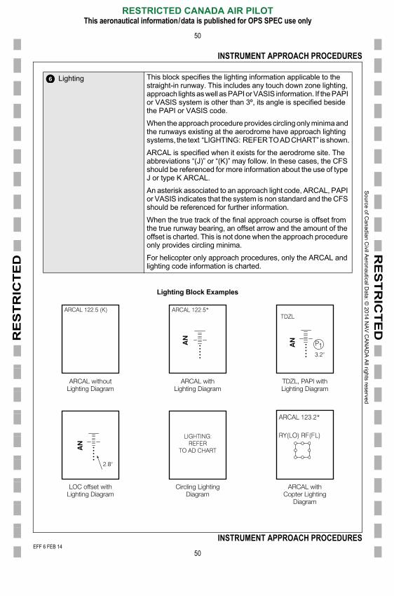
Lighting Block Examples
Lighting This block specifies the lighting information applicable to the straight-in runway. This includes any touch down zone lighting, approach lights as well as PAPI or VASIS information. If the PAPI or VASIS system is other than 3º, its angle is specified beside the PAPI or VASIS code.
When the approach procedure provides circling only minima and the runways existing at the aerodrome have approach lighting systems, the text “LIGHTING: REFER TO AD CHART” is shown.
ARCAL is specified when it exists for the aerodrome site. The abbreviations “(J)” or “(K)” may follow. In these cases, the CFS should be referenced for more information about the use of type J or type K ARCAL.
An asterisk associated to an approach light code, ARCAL, PAPI or VASIS indicates that the system is non standard and the CFS should be referenced for further information.
When the true track of the final approach course is offset from the true runway bearing, an offset arrow and the amount of the offset is charted. This is not done when the approach procedure only provides circling minima.
For helicopter only approach procedures, only the ARCAL and lighting code information is charted.
ARCAL withoutLighting Diagram
ARCAL withLighting Diagram
TDZL, PAPI withLighting Diagram
EFF 6 FEB 14
RESTRICTED CANADA AIR PILOTThis aeronautical information/data is published for OPS SPEC use only
50
INSTRUMENT APPROACH PROCEDURES
LOC offset withLighting Diagram
Circling LightingDiagram
ARCAL withCopter Lighting
Diagram
001/2014
FF 6 FEB 14

So
urce o
f Ca
nad
ian C
ivil Ae
rona
utical D
ata: ©
201
4 NA
V C
AN
AD
A A
ll rights rese
rved
E
RE
ST
RIC
TE
DR
ES
TR
ICT
ED
INSTRUMENT APPROACH PROCEDURES
51
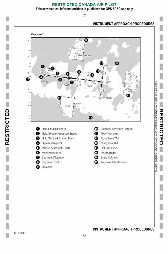
Plan View
The plan view of the approach procedure chart provides a scaled overview of the procedure from an overhead perspective. Data within the plan view is drawn to scale unless a scale break and “NOT TO SCALE” box is shown.
05
1015
2025
Minimum Sector Altitude
Other Land Aerodrome
Missed Approach Track
Localizer NAVAID
Main Aerodrome
VOR/DME NAVAID
NDB NAVAID
Inbound Final Approach Course
No Procedure Turn Required
Circling Restriction
Procedure Turn
Abandoned/Closed Aerodrome
Intersection Symbol
Localizer Front Course
Scale Indication
Obstacle
Built Up Area
Waypoint Symbol
Dead Reckoning Segment
Example 1
EFF 6 FEB 14
RESTRICTED CANADA AIR PILOTThis aeronautical information/data is published for OPS SPEC use only
51
INSTRUMENT APPROACH PROCEDURES
001/2014
FF 6 FEB 14
So
urce o
f Ca
nad
ian C
ivil Ae
rona
utical D
ata: ©
201
4 NA
V C
AN
AD
A A
ll rights rese
rved
E
RE
ST
RIC
TE
DR
ES
TR
ICT
ED
INSTRUMENT APPROACH PROCEDURES
52
05
1015
2025
Hold/Shuttle Pattern
Hold/Shuttle Assessed Speed
Hold/Shuttle Inbound Track
Flyover Waypoint
Missed Approach Track
Main Aerodrome
Segment Distance
Segment Track
Obstacle
Segment Minimum Altitude
Flyby Waypoint
Right Base TAA
Straight-in TAA
Left Base TAA
Hydrography
Scale Indication
Waypoint Identification
Example 2
EFF 6 FEB 14
RESTRICTED CANADA AIR PILOTThis aeronautical information/data is published for OPS SPEC use only
52
INSTRUMENT APPROACH PROCEDURES
001/2014
FF 6 FEB 14
So
urce o
f Ca
nad
ian C
ivil Ae
rona
utical D
ata: ©
201
4 NA
V C
AN
AD
A A
ll rights rese
rved
E
RE
ST
RIC
TE
DR
ES
TR
ICT
ED
INSTRUMENT APPROACH PROCEDURES
53
05
1015
2025
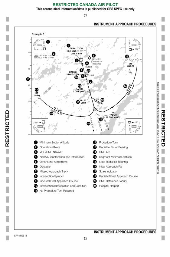
Minimum Sector Altitude
Operational Note
VOR/DME NAVAID
NAVAID Identification and Information
Other Land Aerodrome
Obstacle
Missed Approach Track
Intersection Symbol
Inbound Final Approach Course
Intersection Identification and Definition
No Procedure Turn Required
Procedure Turn
Radial to Fix (or Bearing)
DME Arc
Segment Minimum Altitude
Lead Radial (or Bearing)
Initial Approach Fix
Scale Indication
Radial of Final Approach Course
DME Reference Facility
Hospital Heliport
Example 3
EFF 6 FEB 14
RESTRICTED CANADA AIR PILOTThis aeronautical information/data is published for OPS SPEC use only
53
INSTRUMENT APPROACH PROCEDURES
001/2014
FF 6 FEB 14

So
urce o
f Ca
nad
ian C
ivil Ae
rona
utical D
ata: ©
201
4 NA
V C
AN
AD
A A
ll rights rese
rved
E
RE
ST
RIC
TE
DR
ES
TR
ICT
ED
INSTRUMENT APPROACH PROCEDURES
54
Minimum Sector AltitudesMinimum Sector Altitudes (MSA) are shown as four separate quadrants; one in each corner of the chart’s plan view. Each quadrant is delineated by standard cardinal bearings (090º, 180º, 270º, 360º) to the facility or waypoint.
The bearings are oriented to magnetic north in SDA and to true north in NDA. The MSA radius is 25 NM unless otherwise specified.
For RNAV approach procedures, the MSA altitudes are identical for all four quadrants. When Terminal Arrival Areas (TAA) are charted for an RNAV procedure, MSA altitudes will not be charted.
CYA, CYR and known blasting areas are not considered in the establishment of MSA altitudes. For this reason, it is the pilot’s responsibility to remain clear of these areas as applicable.
Waypoint Symbol
Waypoint Identification
MSA Radius Distance (Non Standard)
Inbound Track to the Waypoint
Minimum Sector Altitude
NAVAID Symbol
NAVAID Identification
Inbound Track to the NAVAID
Northeast MSA Quadrant
Southeast MSA QuadrantSouthwest MSA Quadrant
Northwest MSA Quadrant
EFF 6 FEB 14
RESTRICTED CANADA AIR PILOTThis aeronautical information/data is published for OPS SPEC use only
54
INSTRUMENT APPROACH PROCEDURES
001/2014
FF 6 FEB 14
So
urce o
f Ca
nad
ian C
ivil Ae
rona
utical D
ata: ©
201
4 NA
V C
AN
AD
A A
ll rights rese
rved
E
RE
ST
RIC
TE
DR
ES
TR
ICT
ED
INSTRUMENT APPROACH PROCEDURES
55
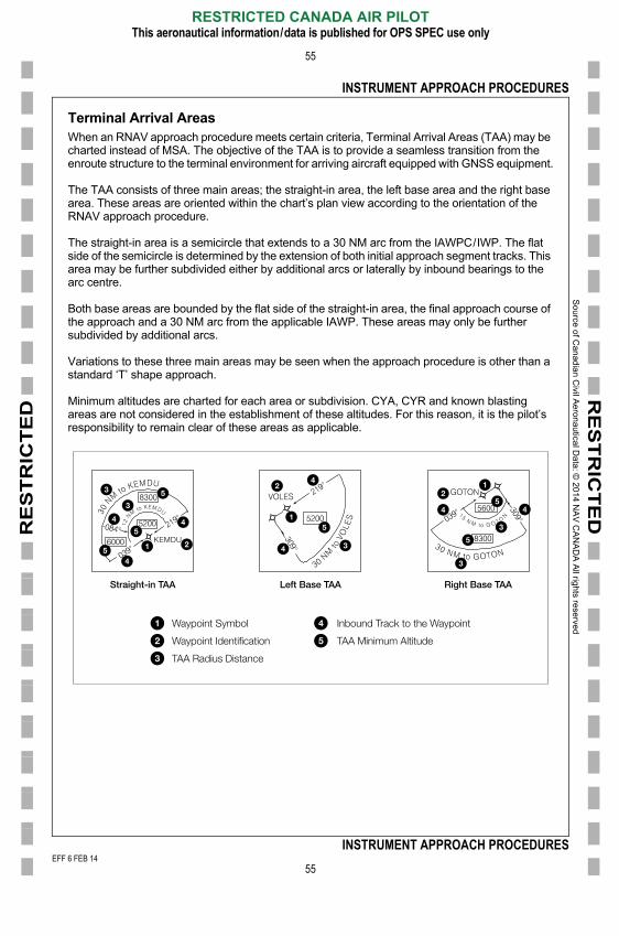
Terminal Arrival AreasWhen an RNAV approach procedure meets certain criteria, Terminal Arrival Areas (TAA) may be charted instead of MSA. The objective of the TAA is to provide a seamless transition from the enroute structure to the terminal environment for arriving aircraft equipped with GNSS equipment.
The TAA consists of three main areas; the straight-in area, the left base area and the right base area. These areas are oriented within the chart’s plan view according to the orientation of the RNAV approach procedure.
The straight-in area is a semicircle that extends to a 30 NM arc from the IAWPC/IWP. The flat side of the semicircle is determined by the extension of both initial approach segment tracks. This area may be further subdivided either by additional arcs or laterally by inbound bearings to the arc centre.
Both base areas are bounded by the flat side of the straight-in area, the final approach course of the approach and a 30 NM arc from the applicable IAWP. These areas may only be further subdivided by additional arcs.
Variations to these three main areas may be seen when the approach procedure is other than a standard ‘T’ shape approach.
Minimum altitudes are charted for each area or subdivision. CYA, CYR and known blasting areas are not considered in the establishment of these altitudes. For this reason, it is the pilot’s responsibility to remain clear of these areas as applicable.
Waypoint Symbol
Waypoint Identification
TAA Radius Distance
Inbound Track to the Waypoint
TAA Minimum Altitude
Straight-in TAA Left Base TAA Right Base TAA
EFF 6 FEB 14
RESTRICTED CANADA AIR PILOTThis aeronautical information/data is published for OPS SPEC use only
55
INSTRUMENT APPROACH PROCEDURES
001/2014
FF 6 FEB 14
So
urce o
f Ca
nad
ian C
ivil Ae
rona
utical D
ata: ©
201
4 NA
V C
AN
AD
A A
ll rights rese
rved
E
RE
ST
RIC
TE
DR
ES
TR
ICT
ED
INSTRUMENT APPROACH PROCEDURES
56
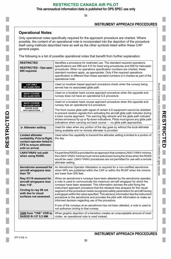
Operational NotesOnly operational notes specifically required for the approach procedure are charted. Where possible, the content of an operational note is incorporated into the depiction of the procedure itself using methods described here as well as the other symbols listed within these CAP general pages.
The following is a list of possible operational notes that benefit from further explanation.
RESTRICTED
RESTRICTED – Ops spec 605 required.
Identifies a procedure for restricted use. The standard required operations specifications are 099 and 410 for fixed wing procedures and 606 for helicopter procedures. When no operations specification numbers are charted, these standard numbers apply, as appropriate. Only if the required operations specification is different than these standard numbers is it charted as part of the operational note.
Used on localizer based approach procedure charts when the runway being served has no associated glide path.
Used on a localizer back course approach procedure when the opposite end runway does not have an operational ILS procedure.
Used on a localizer back course approach procedure when the opposite end runway has an operational ILS procedure.
The front course glide path signal of certain ILS equipment cannot be shielded to prevent random signals from activating the aircraft glide path indicator during a back course approach. The warning flag retracts and the glide path indicator shows erroneous fly-up or fly-down indications. Pilots must ignore any glide path indications when carrying out back course — no glide path approaches.
Altimeter setting Used for sites when any portion of the day goes by without the local altimeter being available and no remote altimeter is provided.
Limited altimeter availability. Prior to flight, contact operator listed in CFS to ensure altimeter avbl on arrival.
Used when the capability to transmit the altimeter setting is limited to a portion of the day.
LNAV/VNAV not auth when using RASS.
If a part time RASS is provided for an approach that contains LNAV/VNAV minima, the LNAV/VNAV minima must not be authorized during the times when the RASS would be used. LNAV/VNAV procedures are not permitted for use with a remote altimeter setting.
Aerodrome assessed for aircraft wingspans less than 79'.
Rwy 01/19 assessed for aircraft wingspans less than 118'.
Circling to rwy 08 not auth due to visual surfaces not assessed.
An Aerodrome Operator Attestation is required for a non-certified aerodrome when IAPs are published within the CAP or within the RCAP when the minima are lower than 500 feet.
When an aerodrome’s runways have been attested by the aerodrome operator, a note is used to communicate the maximum aircraft wingspan for which the runways have been assessed. This information advises the pilot flying the instrument approach procedure that the obstacle free airspace for the visual segment of the procedure meets recognized safety parameters for aircraft having a wingspan within the value specified. This advisory information ties the instrument procedure to the aerodrome and provides the pilot with information to make an
LOC ONLYNO GLIDE PATH
BACK COURSENO GLIDE PATH
BACK COURSENO GLIDE PATH
IGNORE GLIDEPATH INDICATIONS
EFF 6 FEB 14
RESTRICTED CANADA AIR PILOTThis aeronautical information/data is published for OPS SPEC use only
56
INSTRUMENT APPROACH PROCEDURES
informed decision regarding use of the procedure.
If one of the runways at an aerodrome has not been attested, a note is used to not authorize circling to that runway.
3300 from “YXE” VOR to SASOD R-137 5.2 NM.
When graphic depiction of a transition creates an unacceptable amount of chart clutter, an operational note is used instead.
001/2014
FF 6 FEB 14
So
urce o
f Ca
nad
ian C
ivil Ae
rona
utical D
ata: ©
201
4 NA
V C
AN
AD
A A
ll rights rese
rved
EEF
RE
ST
RIC
TE
DR
ES
TR
ICT
ED
INSTRUMENT APPROACH PROCEDURES
57
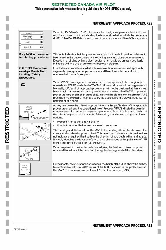
When LNAV/VNAV or RNP minima are included, a temperature limit is shown with the approach minima indicating the temperature below which the procedure (LNAV/VNAV or RNP) is not authorized for uncompensated Baro VNAV systems.
Rwy 14/32 not assessedfor circling procedures.
This note indicates that the given runway (and its threshold positions) has not been used in the development of the circling area and obstacle assessment. Despite this, circling within a given sector is not restricted unless specifically indicated with the use of the circling restriction diagram.
CAUTION: Procedure overlaps Points North Landing (CYNL) procedures.
Used when a procedure’s initial, intermediate, final and/or missed approach segments overlap another procedure at a different aerodrome and is in uncontrolled (class G) airspace.
When WAAS coverage for an aerodrome site is expected to be marginal or unavailable, WAAS predictive NOTAMs for this aerodromes will not be generated. Normally, LPV and LP approach procedures will not be designed at these sites. However, in rare cases where they are, or in cases where LNAV/VNAV approach procedures are designed at these sites, pilots will be alerted to the fact that WAAS predictive NOTAMs are not provided by the depiction of the WAAS negative ‘W’ notation on the chart.
A grey line below the missed approach track in the profile view of the approach procedure chart and the operational note “Proceed VFR” indicate the point-in-space aspect of a helicopter approach procedure. When this is shown, arrival at the missed approach point must be followed by the pilot executing one of two options:
• Proceed VFR to the landing site, or• Conduct the specified missed approach procedure.
The bearing and distance from the MAP to the landing site will be shown on the corresponding visual approach chart. This bearing and distance information does not indicate a required flight path or the direction of approach to the landing site. It simply identifies the location of the landing site relative to the point where VFR flight is accepted by the pilot (i.e. the MAP).
When required for helicopter only procedures, the final and missed approach airspeed limitation will be noted on the applicable segment of the plan view.
For helicopter point-in-space approaches, the height of the MDA above the highest terrain/surface within a 5200' radius of the MAP is shown in the profile view at the MAP. This is known as the Height Above the Surface (HAS).
CATEGORY ALNAV/VNAV(min. -37°C) 33
LNAV 339CIRCLING 354
EFF 29 MAY 14
RESTRICTED CANADA AIR PILOTThis aeronautical information/data is published for OPS SPEC use only
57
INSTRUMENT APPROACH PROCEDURESFF 29 MAY 14
F 6 FEB 14
So
urce o
f Ca
nad
ian C
ivil Ae
rona
utical D
ata: ©
201
4 NA
V C
AN
AD
A A
ll rights rese
rved
EEF
RE
ST
RIC
TE
DR
ES
TR
ICT
ED
INSTRUMENT APPROACH PROCEDURES
58
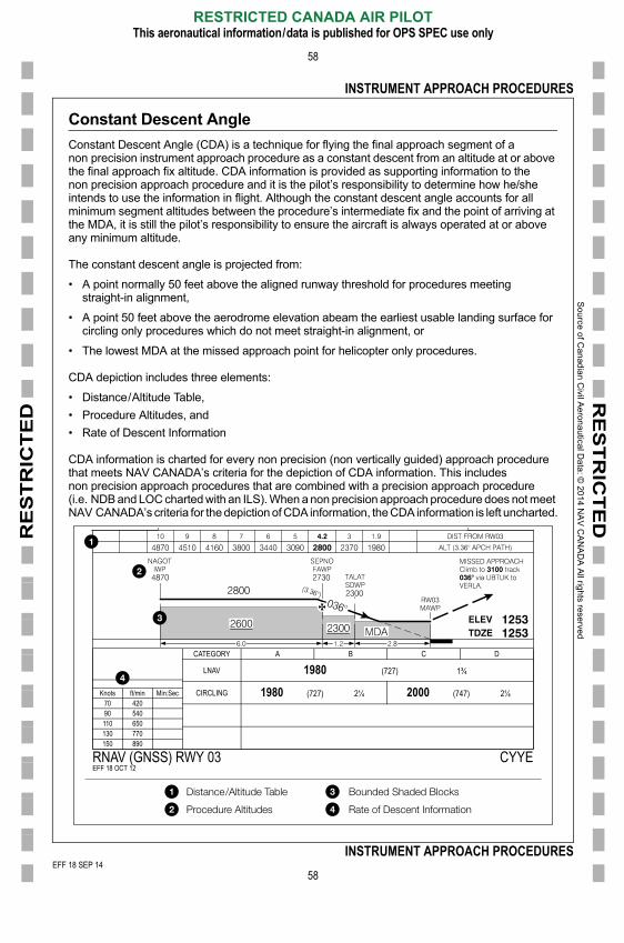
Constant Descent Angle
Constant Descent Angle (CDA) is a technique for flying the final approach segment of a non precision instrument approach procedure as a constant descent from an altitude at or above the final approach fix altitude. CDA information is provided as supporting information to the non precision approach procedure and it is the pilot’s responsibility to determine how he/she intends to use the information in flight. Although the constant descent angle accounts for all minimum segment altitudes between the procedure’s intermediate fix and the point of arriving at the MDA, it is still the pilot’s responsibility to ensure the aircraft is always operated at or above any minimum altitude.
The constant descent angle is projected from:
• A point normally 50 feet above the aligned runway threshold for procedures meeting straight-in alignment,
• A point 50 feet above the aerodrome elevation abeam the earliest usable landing surface for circling only procedures which do not meet straight-in alignment, or
• The lowest MDA at the missed approach point for helicopter only procedures.
CDA depiction includes three elements:
• Distance/Altitude Table,
• Procedure Altitudes, and
• Rate of Descent Information
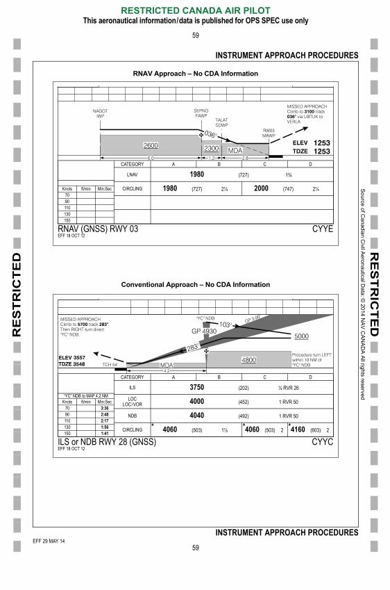
CDA information is charted for every non precision (non vertically guided) approach procedure that meets NAV CANADA’s criteria for the depiction of CDA information. This includes non precision approach procedures that are combined with a precision approach procedure (i.e. NDB and LOC charted with an ILS). When a non precision approach procedure does not meet NAV CANADA’s criteria for the depiction of CDA information, the CDA information is left uncharted.
CATEGORY A B C D
LNAV 1980 (727) 1¾
CIRCLING 1980 (727) 2¼ 2000 (747) 2¼Knots ft/min Min:Sec70 42090 540110 650
EFF 18 SEP 14
RESTRICTED CANADA AIR PILOTThis aeronautical information/data is published for OPS SPEC use only
58
INSTRUMENT APPROACH PROCEDURES
130 770150 890
RNAV (GNSS) RWY 03 CYYEEFF 18 OCT 12
Distance/Altitude Table
Procedure Altitudes
Bounded Shaded Blocks
Rate of Descent Information
FF 18 SEP 14F 6 FEB 14
So
urce o
f Ca
nad
ian C
ivil Ae
rona
utical D
ata: ©
201
4 NA
V C
AN
AD
A A
ll rights rese
rved
EEF
RE
ST
RIC
TE
DR
ES
TR
ICT
ED
INSTRUMENT APPROACH PROCEDURES
59
RNAV Approach – No CDA Information
Conventional Approach – No CDA Information
CATEGORY A B C D
LNAV 1980 (727) 1¾
CIRCLING 1980 (727) 2¼ 2000 (747) 2¼Knots ft/min Min:Sec7090110130150
RNAV (GNSS) RWY 03 CYYEEFF 18 OCT 12
CATEGORY A B C D
ILS (202) ½ RVR 26�YC� NDB to MAP 4.2 NM LOC
LOC/VOR (452) 1 RVR 50Knots ft/min Min:Sec70
NDB (492) 1 RVR 5090110
CIRCLING (503) 1½ (503) 2 (603) 2130150
ILS or NDB RWY 28 (GNSS) CYYCEFF 18 OCT 12
EFF 29 MAY 14
RESTRICTED CANADA AIR PILOTThis aeronautical information/data is published for OPS SPEC use only
59
INSTRUMENT APPROACH PROCEDURESFF 29 MAY 14
F 6 FEB 14
So
urce o
f Ca
nad
ian C
ivil Ae
rona
utical D
ata: ©
201
4 NA
V C
AN
AD
A A
ll rights rese
rved
E
RE
ST
RIC
TE
DR
ES
TR
ICT
ED
INSTRUMENT APPROACH PROCEDURES
60
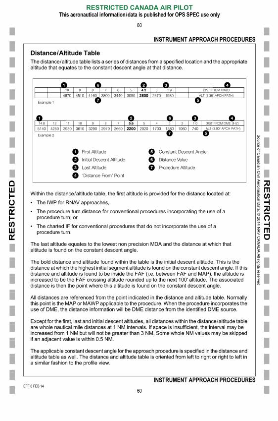
Distance/Altitude TableThe distance/altitude table lists a series of distances from a specified location and the appropriate altitude that equates to the constant descent angle at that distance.
Within the distance/altitude table, the first altitude is provided for the distance located at:
• The IWP for RNAV approaches,
• The procedure turn distance for conventional procedures incorporating the use of a procedure turn, or
• The charted IF for conventional procedures that do not incorporate the use of a procedure turn.
The last altitude equates to the lowest non precision MDA and the distance at which that altitude is found on the constant descent angle.
The bold distance and altitude found within the table is the initial descent altitude. This is the distance at which the highest initial segment altitude is found on the constant descent angle. If this distance and altitude is found to be inside the FAF (i.e. between FAF and MAP), the altitude is increased to be the FAF crossing altitude rounded up to the next 100' altitude. The associated distance is then the point where this altitude is found on the constant descent angle.
All distances are referenced from the point indicated in the distance and altitude table. Normally this point is the MAP or MAWP applicable to the procedure. When the procedure incorporates the use of DME, the distance information will be DME distance from the identified DME source.
Except for the first, last and initial descent altitudes, all distances within the distance/altitude table
First Altitude
Initial Descent Altitude
Last Altitude
‘Distance From’ Point
Constant Descent Angle
Distance Value
Procedure Altitude
Example 1
Example 2
EFF 6 FEB 14
RESTRICTED CANADA AIR PILOTThis aeronautical information/data is published for OPS SPEC use only
60
INSTRUMENT APPROACH PROCEDURES
are whole nautical mile distances at 1 NM intervals. If space is insufficient, the interval may be increased from 1 NM but will not be greater than 3 NM. Some whole NM values may be skipped if an adjacent value is within 0.5 NM.
The applicable constant descent angle for the approach procedure is specified in the distance and altitude table as well. The distance and altitude table is oriented from left to right or right to left in a similar fashion to the profile view.
001/2014
FF 6 FEB 14

So
urce o
f Ca
nad
ian C
ivil Ae
rona
utical D
ata: ©
201
4 NA
V C
AN
AD
A A
ll rights rese
rved
EEF
RE
ST
RIC
TE
DR
ES
TR
ICT
ED
INSTRUMENT APPROACH PROCEDURES
61
Procedure AltitudesAll procedure altitudes are shown within the profile view as recommended altitudes (not underlined). Minimum segment altitudes are underlined and shown within bounded shaded blocks. The profile view of the approach procedure chart shows the initial descent altitude above the level flight track line prior to the descent point except when a procedure turn is depicted. When a procedure turn is depicted, the standard procedure turn profile view symbol is used and the altitude is underlined to indicate that it is a minimum altitude.
Other procedure altitudes are shown in the profile view for each charted fix. When a non precision approach procedure is charted with an ILS procedure, the ILS glide path check altitude serves as the procedure altitude for that fix.
Rate of Descent InformationWhen CDA is charted for a procedure, rate of descent information applicable to the constant descent angle is shown. This information is shown as feet/minute descent rates applicable to the given ground speed values.
EFF 18 SEP 14
RESTRICTED CANADA AIR PILOTThis aeronautical information/data is published for OPS SPEC use only
61
INSTRUMENT APPROACH PROCEDURESFF 18 SEP 14
F 6 FEB 14
So
urce o
f Ca
nad
ian C
ivil Ae
rona
utical D
ata: ©
201
4 NA
V C
AN
AD
A A
ll rights rese
rved
E
RE
ST
RIC
TE
DR
ES
TR
ICT
ED
INSTRUMENT APPROACH PROCEDURES
62
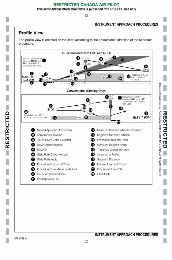
Profile View
The profile view is oriented on the chart according to the predominant direction of the approach procedure.
Missed Approach Instruction
Aerodrome Elevation
Touch Down Zone Elevation
NAVAID Identification
NAVAID
Glide Path Check Altitude
Glide Path Angle
Procedure Outbound Track
Procedure Turn Minimum Altitude
Bounded Shaded Block
Final Approach Fix
Minimum Descent Altitude Indication
Segment Minimum Altitude
Procedure Inbound Track
Constant Descent Angle
Threshold Crossing Height
Aerodrome Profile
Segment Distance
Missed Approach Track
Procedure Turn Note
Glide Path
ILS (Combined with LOC and NDB)
Conventional (Circling Only)
EFF 6 FEB 14
RESTRICTED CANADA AIR PILOTThis aeronautical information/data is published for OPS SPEC use only
62
INSTRUMENT APPROACH PROCEDURES
001/2014
FF 6 FEB 14
So
urce o
f Ca
nad
ian C
ivil Ae
rona
utical D
ata: ©
201
4 NA
V C
AN
AD
A A
ll rights rese
rved
E
RE
ST
RIC
TE
DR
ES
TR
ICT
ED
INSTRUMENT APPROACH PROCEDURES
63
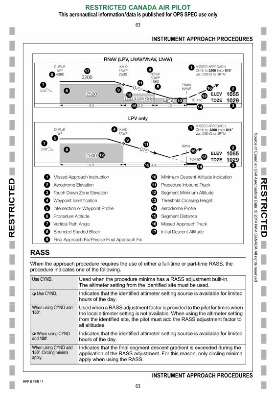
RASS
When the approach procedure requires the use of either a full-time or part-time RASS, the procedure indicates one of the following.
Use CYND. Used when the procedure minima has a RASS adjustment built-in. The altimeter setting from the identified site must be used.
Use CYND. Indicates that the identified altimeter setting source is available for limited hours of the day.
When using CYND add 150'.
Used when a RASS adjustment factor is provided to the pilot for times when the local altimeter setting is not available. When using the altimeter setting
Missed Approach Instruction
Aerodrome Elevation
Touch Down Zone Elevation
Waypoint Identification
Intersection or Waypoint Profile
Procedure Altitude
Vertical Path Angle
Bounded Shaded Block
Final Approach Fix/Precise Final Approach Fix
Minimum Descent Altitude Indication
Procedure Inbound Track
Segment Minimum Altitude
Threshold Crossing Height
Aerodrome Profile
Segment Distance
Missed Approach Track
Initial Descent Altitude
RNAV (LPV, LNAV/VNAV, LNAV)
LPV only
EFF 6 FEB 14
RESTRICTED CANADA AIR PILOTThis aeronautical information/data is published for OPS SPEC use only
63
INSTRUMENT APPROACH PROCEDURES
from the identified site, the pilot must add the RASS adjustment factor to all altitudes.
When using CYND add 150'.
Indicates that the identified altimeter setting source is available for limited hours of the day.
When using CYND add 150'. Circling minima apply.
Indicates that the final segment descent gradient is exceeded during the application of the RASS adjustment. For this reason, only circling minima apply when using the RASS.
001/2014
FF 6 FEB 14
So
urce o
f Ca
nad
ian C
ivil Ae
rona
utical D
ata: ©
201
4 NA
V C
AN
AD
A A
ll rights rese
rved
E
RE
ST
RIC
TE
DR
ES
TR
ICT
ED
INSTRUMENT APPROACH PROCEDURES
64
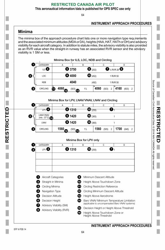
Minima
The minima box of the approach procedure chart lists one or more navigation type requirements and the associated minimum altitudes (MDA or DA), heights (HAA, HAT, HATh or DH) and advisory visibility for each aircraft category. In addition to statute miles, the advisory visibility is also provided as an RVR value when the straight-in runway has an associated RVR sensor and the advisory visibility is 1 SM or less.
CATEGORY A B C D
ILS 3750 (202) ½ RVR 26
LOC 4000 (452) 1 RVR 50
NDB 4040 (492) 1 RVR 50
CIRCLING * 4060 (503) 1½ *4060 (503) 2 *4160 (603) 2
CATEGORY A B C D
LPV 1310 (255) 1
LNAV/VNAV(min. -37°C) 1420 (365) 1
LNAV 1420 (365) 1
CIRCLING 1560 (505) 1½ 1560 (505) 2 1700 (645) 2
CATEGORY A B C D
LPV 1310 (255) 1
Aircraft Categories
Straight-in Minima
Circling Minima
Navigation Type
Minimum Descent Altitude
Height Above Touchdown Zone
Circling Restriction Reference
Circling Minimum Descent Altitude
Minima Box for ILS, LOC, NDB and Circling
Minima Box for LPV, LNAV/VNAV, LNAV and Circling
Minima Box for LPV only
EFF 6 FEB 14
RESTRICTED CANADA AIR PILOTThis aeronautical information/data is published for OPS SPEC use only
64
INSTRUMENT APPROACH PROCEDURES
Decision Altitude
Decision Height
Advisory Visibility (SM)
Advisory Visibility (RVR)
Height Above Aerodrome
Baro VNAV Minimum Temperature Limitation(applicable to uncompensated Baro VNAV systems)
Decision Height or Height Above Threshold
Height Above Touchdown Zone orHeight Above Threshold
001/2014
FF 6 FEB 14

So
urce o
f Ca
nad
ian C
ivil Ae
rona
utical D
ata: ©
201
4 NA
V C
AN
AD
A A
ll rights rese
rved
E
RE
ST
RIC
TE
DR
ES
TR
ICT
ED
INSTRUMENT APPROACH PROCEDURES
65
Additional navigation requirements, beyond what is listed in the procedure identification, are indicated within the minima lines of the approach
• ILS/DME• LOC/DME• LNAV/VNAV• LPV
An LP minima line indicates a WAAS based RNAV non precision (non vertically guided) approach procedure.
The circling procedure minima provided on an approach chart is always based on the non precision (non vertically guided) components of the chart (missed approach point, etc.). When a procedure chart does not include a non precision (non vertically guided) procedure, circling minima are not provided. Circling minima are always at or above the straight-in minima (MDA) of the non precision procedures depicted on the same chart. In rare situations, the circling minima may be lower than the charted LNAV/VNAV straight-in minima due to the application of procedure design criteria.
The appropriate aircraft category and resulting approach minima are determined by the pilot based on the airspeed at which the aircraft is to be manoeuvered. The aircraft categories are defined as follows. Category E is not charted for civil approach procedures.
Only minima that are authorized to be flown as part of the approach procedure are shown. Absence of charted approach minima for a specific navigation type (i.e. LNAV/VNAV, circling, etc.) indicates the procedure type is not authorized to be flown.
When LNAV/VNAV or RNP minima are included, a temperature limit is shown with the approach minima. This indicates the temperature below which the procedure (LNAV/VNAV or RNP) is not authorized for use when using an uncompensated Baro VNAV system.
Rate of Descent and Timing
When required, rate of descent and timing information is provided for the identified ground speed values.
Category A or COPTER B C D E
Speeds up to 90 kt(includes all rotorcraft)
91 to 120 kt 121 to 140 kt 141 to 165 kt above 165 kt
�YC� NDB to MAP 4.2 NMKnots ft/min Min:Sec
70 370 3:3690 480 2:48110 580 2:17130 690 1:56150 800 1:41
Distance Statement
Ground Speed
Rate of Descent
Timing Information
EFF 6 FEB 14
RESTRICTED CANADA AIR PILOTThis aeronautical information/data is published for OPS SPEC use only
65
INSTRUMENT APPROACH PROCEDURES
Rate of descent information is provided as a feet/minute value when CDA information is charted for the approach procedure and corresponds to the constant descent angle charted for the approach.
Timing information is provided when the approach procedure contains a conventional MAP defined by distance from the FAF. The defined distance of the MAP from the FAF is translated into the number of minutes and seconds to be flown at the specified ground speed value.
001/2014
FF 6 FEB 14

So
urce o
f Ca
nad
ian C
ivil Ae
rona
utical D
ata: ©
201
4 NA
V C
AN
AD
A A
ll rights rese
rved
EEF
RE
ST
RIC
TE
DR
ES
TR
ICT
ED
INSTRUMENT APPROACH PROCEDURES
66
Helicopter Only Approach ChartAlthough the helicopter only approach chart is similar to the generic approach chart, there are a number of differences.
1. The procedure identification of a helicopter only approach procedure is always prefixed with the term “COPTER”. When the procedure is not to a runway, the procedure identification incorporates the use of the final approach course instead of a runway number.
i.e. COPTER RNAV (GNSS) 049º
2. The only approach category charted on the helicopter only approach chart is the “COPTER” category. This equates to category A.
3. Circling minima are not charted for helicopter only approach procedures.
4. Point-in-space helicopter approach procedures are identified by charting the “Proceed VFR” note associated with the grey line under the missed approach track in the profile view. The presence of this note indicates that once the pilot reaches the MAP, he/she must proceed VFR from the MAP to the landing area or conduct the specified missed approach procedure. The bearing and distance from the MAP to the landing site is shown on the accompanying visual approach chart. This bearing and distance information does not indicate a required flight path or the direction of approach to the landing site. It simply identifies the location of the landing site relative to the point where VFR flight is accepted by the pilot (i.e. the MAP).
5. Point-in-space helicopter approach procedures indicate a HAS value at the MAP in the profile view. The HAS is the height of the MDA above the highest terrain/surface within a 5,200' radius of the MAP.
6. For RNAV (GNSS) helicopter only approaches:
• When no maximum airspeed is charted on the final and missed approach segment, the maximum final and missed approach airspeed limitation is 90 knots. Final and missed approach maximum airspeed limitations are only charted when they are less than 90 knots. The missed approach airspeed limitation applies until the aircraft is established on the inbound course to the missed approach clearance limit.
• Approach mode is to be armed 30 NM prior to the HRP/AGCC.
7. All helicopter only approach procedures that do not have a MAP coincident with a runway threshold have a supplementary visual approach chart.
EFF 29 MAY 14
RESTRICTED CANADA AIR PILOTThis aeronautical information/data is published for OPS SPEC use only
66
INSTRUMENT APPROACH PROCEDURESFF 29 MAY 14
F 6 FEB 14
So
urce o
f Ca
nad
ian C
ivil Ae
rona
utical D
ata: ©
201
4 NA
V C
AN
AD
A A
ll rights rese
rved
E
RE
ST
RIC
TE
DR
ES
TR
ICT
ED
INSTRUMENT APPROACH PROCEDURES
67
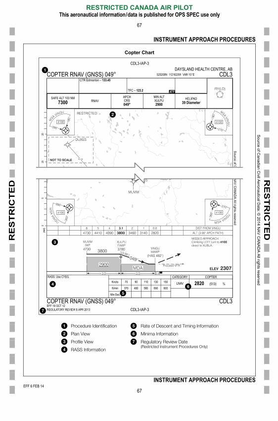
Copter Chart
13 NA
V C
AN
AD
A A
ll rights reserved
CDL3-IAP-3
05
(NM
)
RASS: Use CYEG. CATEGORY COPTERKnots 70 90 110 130 150 LNAV (513) ¾ft/min 370 480 580 690 800
Min:Sec
COPTER RNAV (GNSS) 049° CDL3EFF 18 OCT 12REGULATORY REVIEW 8 APR 2013
Source of C
CDL3-IAP-3
2025
DAYSLAND HEALTH CENTRE, ABCOPTER RNAV (GNSS) 049° 525208N 1121623W VAR 15°E CDL3
CTR Edmonton �
TFC �
SAFE ALT 100 NMRNAV
APCHCRS
MIN ALTXULPU HELIPAD
EFF 6 FEB 14
RESTRICTED CANADA AIR PILOTThis aeronautical information/data is published for OPS SPEC use only
67
INSTRUMENT APPROACH PROCEDURES
Procedure Identification
Plan View
Profile View
RASS Information
Rate of Descent and Timing Information
Minima Information
Regulatory Review Date(Restricted Instrument Procedures Only)
001/2014
FF 6 FEB 14
So
urce o
f Ca
nad
ian C
ivil Ae
rona
utical D
ata: ©
201
4 NA
V C
AN
AD
A A
ll rights rese
rved
EEF
RE
ST
RIC
TE
DR
ES
TR
ICT
ED
INSTRUMENT APPROACH PROCEDURES
68
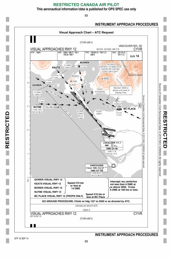
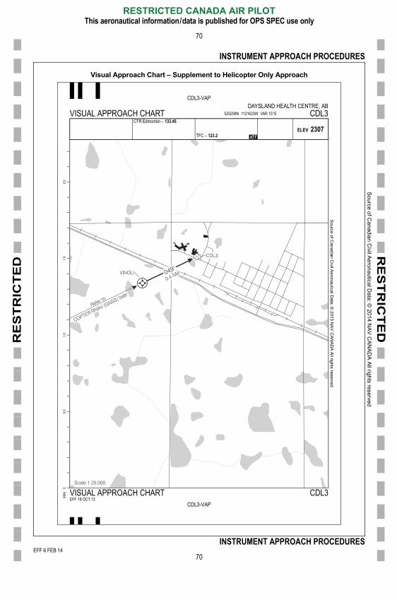
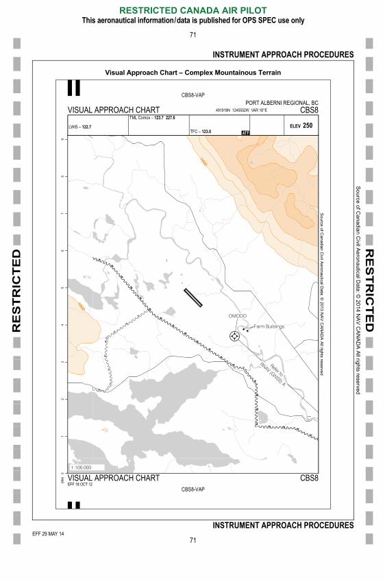
Visual Approach ChartVisual approach charts are provided in three cases:
1. On request from air traffic control,
2. As a supplement to helicopter only approaches where the MAP is not a runway threshold, and
3. Sites having approach procedures and located within complex mountainous terrain. Complex mountainous terrain is defined according to NAV CANADA specifications.
When a visual approach chart is provided for a specific runway, the applicable runway is identified in its procedure identification (i.e. VISUAL APPROACH RWY 26L). If the visual approach chart applies to the site in general and is not specific to a runway, it is identified simply as VISUAL APPROACH CHART.
In cases where the visual approach chart is provided as supplementary information to a helicopter only approach, the bearing and distance from the MAP to the landing site are shown. This bearing and distance information does not indicate a required flight path or the direction of approach to the landing site. It simply identifies the location of the landing site relative to the point where VFR flight is accepted by the pilot (i.e. the MAP).
EFF 29 MAY 14
RESTRICTED CANADA AIR PILOTThis aeronautical information/data is published for OPS SPEC use only
68
INSTRUMENT APPROACH PROCEDURESFF 29 MAY 14
F 6 FEB 14
So
urce o
f Ca
nad
ian C
ivil Ae
rona
utical D
ata: ©
201
4 NA
V C
AN
AD
A A
ll rights rese
rved
EEF
RE
ST
RIC
TE
DR
ES
TR
ICT
ED
INSTRUMENT APPROACH PROCEDURES
69
Visual Approach Chart – ATC Request• Waiting for Vancouver COMM to finish creating this graphic
Source of C
anadian Civil Aeronautical D
ata: © 2013 N
AV
CA
NA
DA
All rights reserved
CYVR-VAP-2VANCOUVER INTL, BC
VISUAL APPROACHES RWY 12 491141N 1231102W VAR 17°E CYVRATIS � ARR � TWR � (N) (S) GND � (N)
(S)
EFF 22 AUG 13
05
(NM
)10
1520
EFF 18 SEP 14
RESTRICTED CANADA AIR PILOTThis aeronautical information/data is published for OPS SPEC use only
69
INSTRUMENT APPROACH PROCEDURES
CYVR-VAP-2
VISUAL APPROACHES RWY 12 CYVREFF 18 OCT 12
FF 18 SEP 14F 6 FEB 14
So
urce o
f Ca
nad
ian C
ivil Ae
rona
utical D
ata: ©
201
4 NA
V C
AN
AD
A A
ll rights rese
rved
E
RE
ST
RIC
TE
DR
ES
TR
ICT
ED
INSTRUMENT APPROACH PROCEDURES
70
Visual Approach Chart – Supplement to Helicopter Only Approach
Source of C
anadian Civil A
eronautical Data: ©
2013 NA
V C
AN
AD
A All rights reserved
CDL3-VAP
0.5
1.0
1.5
2.0
DAYSLAND HEALTH CENTRE, ABVISUAL APPROACH CHART 525208N 1121623W VAR 15°E CDL3
CTR Edmonton �
TFC �
EFF 6 FEB 14
RESTRICTED CANADA AIR PILOTThis aeronautical information/data is published for OPS SPEC use only
70
INSTRUMENT APPROACH PROCEDURES
CDL3-VAP
0(N
M) VISUAL APPROACH CHART CDL3
EFF 18 OCT 12
001/2014
FF 6 FEB 14
So
urce o
f Ca
nad
ian C
ivil Ae
rona
utical D
ata: ©
201
4 NA
V C
AN
AD
A A
ll rights rese
rved
EEF
RE
ST
RIC
TE
DR
ES
TR
ICT
ED
INSTRUMENT APPROACH PROCEDURES
71
Visual Approach Chart – Complex Mountainous Terrain
Source of C
anadian Civil A
eronautical Data: ©
2013 NA
V C
AN
AD
A All rights reserved
CBS8-VAP
12
34
56
78
9
PORT ALBERNI REGIONAL, BCVISUAL APPROACH CHART 491919N 1245552W VAR 18°E CBS8
LWIS �
TML Comox �
TFC �
EFF 29 MAY 14
RESTRICTED CANADA AIR PILOTThis aeronautical information/data is published for OPS SPEC use only
71
INSTRUMENT APPROACH PROCEDURES
CBS8-VAP
0(N
M) VISUAL APPROACH CHART CBS8
EFF 18 OCT 12
FF 29 MAY 14F 6 FEB 14

So
urce o
f Ca
nad
ian C
ivil Ae
rona
utical D
ata: ©
201
4 NA
V C
AN
AD
A A
ll rights rese
rved
EEF
RE
ST
RIC
TE
DR
ES
TR
ICT
ED
INSTRUMENT APPROACH PROCEDURES
72
ILS CAT II or III Approach ChartMost of the information charted on the ILS CAT II or III approach chart is similar to the generic approach chart. The main difference is found in the minima and terrain profile view. Operation to category II or category III minima is not authorized unless specific authorization has been obtained from Transport Canada or the equivalent military authority.
ILS CAT II or III Approach Chart
05
(NM
)D
ata: © 2013 N
AV
CA
NA
DA
All rights reserved
PRIOR AUTH REQUIRED FROM TC
CAT II 664 (100) RVR 12
CAT III A RVR 6
CAT III B NOT AUTHORIZED
CAT III C NOT AUTHORIZED
2025
Source
CYYZ-IAP-2BTORONTO/LESTER B. PEARSON INTL, ON
ILS CAT II or III RWY 05 434036N 0793750W VAR 10°W CYYZATIS � 120.82 ARR � 132.8 124.47 125.4 TWR � 118.7 118.35 GND � 121.65 121.9
119.1
SAFE ALT 100 NM4900
LOCITX
109.7
APCHCRS057°
GPZLP
1920LDA
10640
EFF 18 SEP 14
RESTRICTED CANADA AIR PILOTThis aeronautical information/data is published for OPS SPEC use only
72
INSTRUMENT APPROACH PROCEDURES
CYYZ-IAP-2B
ILS CAT II or III RWY 05 CYYZEFF 18 OCT 12
FF 18 SEP 14F 6 FEB 14
So
urce o
f Ca
nad
ian C
ivil Ae
rona
utical D
ata: ©
201
4 NA
V C
AN
AD
A A
ll rights rese
rved
E
RE
ST
RIC
TE
DR
ES
TR
ICT
ED
INSTRUMENT APPROACH PROCEDURES
73
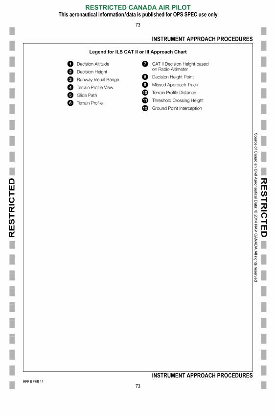
Legend for ILS CAT II or III Approach Chart
Decision Altitude
Decision Height
Runway Visual Range
Terrain Profile View
Glide Path
Terrain Profile
CAT II Decision Height basedon Radio Altimeter
Decision Height Point
Missed Approach Track
Terrain Profile Distance
Threshold Crossing Height
Ground Point Interception
EFF 6 FEB 14
RESTRICTED CANADA AIR PILOTThis aeronautical information/data is published for OPS SPEC use only
73
INSTRUMENT APPROACH PROCEDURES
001/2014
FF 6 FEB 14
RE
ST
RIC
TE
D
Sou
rce of C
an
adia
n Civil A
eron
autica
l Data
: © 20
14 N
AV
CA
NA
DA
All righ
ts reserve
d
E
RE
ST
RIC
TE
D
74
STANDARD INSTRUMENT DEPARTURES
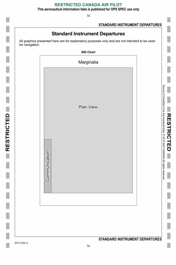
Standard Instrument DeparturesAll graphics presented here are for explanatory purposes only and are not intended to be used for navigation.
SID Chart
Marginalia
Plan View
Com
mun
icat
ion
EFF 6 FEB 14
RESTRICTED CANADA AIR PILOTThis aeronautical information/data is published for OPS SPEC use only
74
STANDARD INSTRUMENT DEPARTURES
001/2014
FF 6 FEB 14
So
urce o
f Ca
nad
ian C
ivil Ae
rona
utical D
ata: ©
201
4 NA
V C
AN
AD
A A
ll rights rese
rved
E
RE
ST
RIC
TE
DR
ES
TR
ICT
ED
STANDARD INSTRUMENT DEPARTURES
75
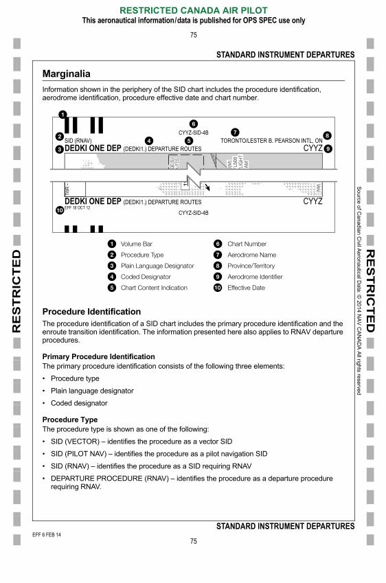
Marginalia
Information shown in the periphery of the SID chart includes the procedure identification, aerodrome identification, procedure effective date and chart number.
Procedure IdentificationThe procedure identification of a SID chart includes the primary procedure identification and the enroute transition identification. The information presented here also applies to RNAV departure procedures.
Primary Procedure IdentificationThe primary procedure identification consists of the following three elements:
• Procedure type
• Plain language designator
• Coded designator
Procedure TypeThe procedure type is shown as one of the following:
• SID (VECTOR) – identifies the procedure as a vector SID
CYYZ-SID-4BSID (RNAV) TORONTO/LESTER B. PEARSON INTL, ONDEDKI ONE DEP (DEDKI1.) DEPARTURE ROUTES CYYZ
CYYZ-SID-4B
TWR
� 118
.
DEDKI ONE DEP (DEDKI1.) DEPARTURE ROUTES CYYZEFF 18 OCT 12
Volume Bar
Procedure Type
Plain Language Designator
Coded Designator
Chart Content Indication
Chart Number
Aerodrome Name
Province/Territory
Aerodrome Identifier
Effective Date
EFF 6 FEB 14
RESTRICTED CANADA AIR PILOTThis aeronautical information/data is published for OPS SPEC use only
75
STANDARD INSTRUMENT DEPARTURES
• SID (PILOT NAV) – identifies the procedure as a pilot navigation SID
• SID (RNAV) – identifies the procedure as a SID requiring RNAV
• DEPARTURE PROCEDURE (RNAV) – identifies the procedure as a departure procedure requiring RNAV.
001/2014
FF 6 FEB 14

So
urce o
f Ca
nad
ian C
ivil Ae
rona
utical D
ata: ©
201
4 NA
V C
AN
AD
A A
ll rights rese
rved
EEF
RE
ST
RIC
TE
DR
ES
TR
ICT
ED
STANDARD INSTRUMENT DEPARTURES
76
Plain Language DesignatorThe plain language designator is the spoken identification for the SID procedure. It consists of a basic indicator, validity number and the term “DEP”. The validity number is a number between 1 and 9 assigned sequentially after a qualifying procedure amendment. A qualifying procedure amendment is a change in a procedure track or other significant change affecting the database coding of the procedure.
• WINNIPEG TWO DEP
• BOMET SIX DEP
Coded DesignatorThe coded designator is the database/flight planning identification for the SID procedure. It consists of a coded version of the plain language basic indicator and the validity number.
• (CYWG2.)
• (BOMET6.)
Similar to the procedure identification of approach procedures, the primary procedure identification for SID procedures may be suffixed with one or both of the following suffixes.
• (TRUE) Identifies the procedure as existing in NDA
• (DND) Identifies the procedure as a procedure designed and maintained by theDepartment of National Defence
Enroute Transition IdentificationWhen a SID procedure includes transitions to the enroute airspace structure, the en route transitions are identified in similar fashion to the main SID procedure. The enroute transition identification includes a plain language designator and a coded designator. The plain language designator is the spoken identification for the en route transition and is usually derived from the name of the last point of the enroute transition. The coded designator is the database/flight planning identification for the enroute transition and is derived from both the primary procedure identification and the en route transition plain language designator.
• MIVOK TRANSITION: (BOMET6.MIVOK)
• HIGH LEVEL TRANSITION: (ROVNA1.YOJ)
Communication
The communication information shown on a SID chart follows the principles explained for the
Plain Language Designator
Coded Designator
EFF 18 SEP 14
RESTRICTED CANADA AIR PILOTThis aeronautical information/data is published for OPS SPEC use only
76
STANDARD INSTRUMENT DEPARTURES
instrument approach procedure charts. The tower system and departure system of the departure string apply to SID charts.
DEP � 128.8 127.57TWR � 118.35 118.7Tower System
Departure System
FF 18 SEP 14F 6 FEB 14
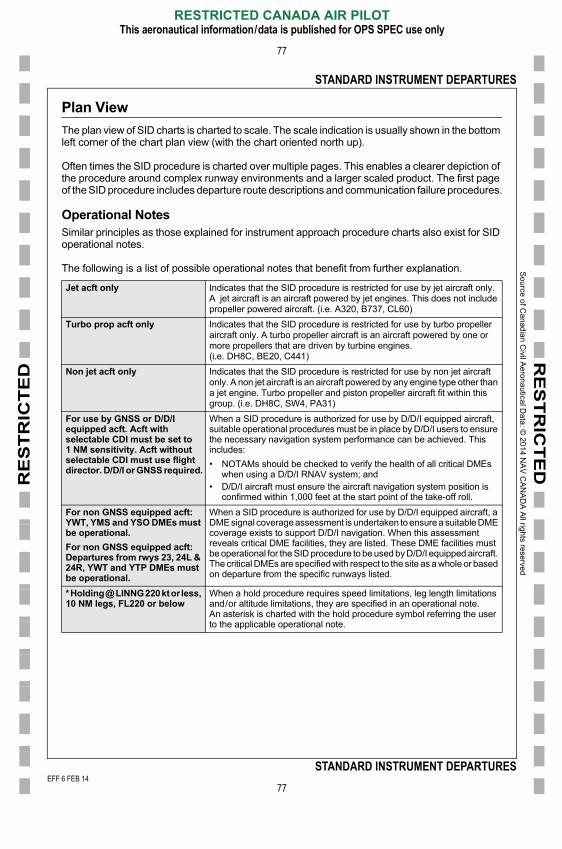
So
urce o
f Ca
nad
ian C
ivil Ae
rona
utical D
ata: ©
201
4 NA
V C
AN
AD
A A
ll rights rese
rved
E
RE
ST
RIC
TE
DR
ES
TR
ICT
ED
STANDARD INSTRUMENT DEPARTURES
77
Plan View
The plan view of SID charts is charted to scale. The scale indication is usually shown in the bottom left corner of the chart plan view (with the chart oriented north up).
Often times the SID procedure is charted over multiple pages. This enables a clearer depiction of the procedure around complex runway environments and a larger scaled product. The first page of the SID procedure includes departure route descriptions and communication failure procedures.
Operational NotesSimilar principles as those explained for instrument approach procedure charts also exist for SID operational notes.
The following is a list of possible operational notes that benefit from further explanation.
Jet acft only Indicates that the SID procedure is restricted for use by jet aircraft only. A jet aircraft is an aircraft powered by jet engines. This does not include propeller powered aircraft. (i.e. A320, B737, CL60)
Turbo prop acft only Indicates that the SID procedure is restricted for use by turbo propeller aircraft only. A turbo propeller aircraft is an aircraft powered by one or more propellers that are driven by turbine engines.(i.e. DH8C, BE20, C441)
Non jet acft only Indicates that the SID procedure is restricted for use by non jet aircraft only. A non jet aircraft is an aircraft powered by any engine type other than a jet engine. Turbo propeller and piston propeller aircraft fit within this group. (i.e. DH8C, SW4, PA31)
For use by GNSS or D/D/I equipped acft. Acft with selectable CDI must be set to 1 NM sensitivity. Acft without selectable CDI must use flight director. D/D/I or GNSS required.
When a SID procedure is authorized for use by D/D/I equipped aircraft, suitable operational procedures must be in place by D/D/I users to ensure the necessary navigation system performance can be achieved. This includes:
• NOTAMs should be checked to verify the health of all critical DMEs when using a D/D/I RNAV system; and
• D/D/I aircraft must ensure the aircraft navigation system position is confirmed within 1,000 feet at the start point of the take-off roll.
For non GNSS equipped acft: YWT, YMS and YSO DMEs must be operational.
For non GNSS equipped acft: Departures from rwys 23, 24L & 24R, YWT and YTP DMEs must be operational.
When a SID procedure is authorized for use by D/D/I equipped aircraft, a DME signal coverage assessment is undertaken to ensure a suitable DME coverage exists to support D/D/I navigation. When this assessment reveals critical DME facilities, they are listed. These DME facilities must be operational for the SID procedure to be used by D/D/I equipped aircraft. The critical DMEs are specified with respect to the site as a whole or based on departure from the specific runways listed.
* Holding @ LINNG 220 kt or less, 10 NM legs, FL220 or below
When a hold procedure requires speed limitations, leg length limitations and/or altitude limitations, they are specified in an operational note.An asterisk is charted with the hold procedure symbol referring the user to the applicable operational note.
EFF 6 FEB 14
RESTRICTED CANADA AIR PILOTThis aeronautical information/data is published for OPS SPEC use only
77
STANDARD INSTRUMENT DEPARTURES
001/2014
FF 6 FEB 14

So
urce o
f Ca
nad
ian C
ivil Ae
rona
utical D
ata: ©
201
4 NA
V C
AN
AD
A A
ll rights rese
rved
E
RE
ST
RIC
TE
DR
ES
TR
ICT
ED
STANDARD INSTRUMENT DEPARTURES
78
RNAV SID
Source of C
anadian Civil Aeronautical D
ata: © 2013 N
AV
CA
NA
DA
All rights reserved
CYYZ-SID-4ASID (RNAV) TORONTO/LESTER B. PEARSON INTL, ONDEDKI ONE DEP (DEDKI1.) CYYZ
Departure Route DescriptionUnless otherwise assigned by ATC:
All rwys: Maintain 5000.
Rwy 05: Depart rwy 05, climb hdg 057° to 1000. Climbing LEFT turn hdg 047° or as assigned. Expect radar vectors to ALKUT (or as assigned) then proceed via depicted route.
Rwy 06L: Requires a minimum climb gradient of 220 ft/NM to 1100. Depart rwy 06L, climb hdg 057° to 1000. Continue climb hdg 057° or as assigned. Expect radar vectors to ALKUT (or as assigned) then proceed via depicted route.
Rwy 06R: Requires a minimum climb gradient of 210 ft/NM to 1500. Depart rwy 06R, climb hdg 057° to 1000. Continue climb hdg 057° or as assigned. Expect radar vectors to ALKUT (or as assigned) then proceed via depicted route.
Rwy 15L: Requires a minimum climb gradient of 410 ft/NM to 3000. Depart rwy 15L, climb hdg 147° or as assigned. Expect radar vectors to DEDKI (or as assigned) then proceed via depicted route.
Rwy 15R: Requires a minimum climb gradient of 390 ft/NM to 3000. Depart rwy 15R, climb hdg 147° or as assigned. Expect radar vectors to DEDKI (or as assigned) then proceed via depicted route.
Rwy 23: Depart rwy 23, climb hdg 237° to 1100. Climbing RIGHT turn hdg 245° or as assigned. Expect radar vectors to SAVUR (or as assigned) then proceed via depicted route.
Rwys 24L & 24R: Depart rwy 24L/R, climb hdg 237° to 1000. Climbing LEFT turn hdg 235° or as assigned. Expect radar vectors to SAVUR (or as assigned) then proceed via depicted route.
Rwy 33L: Requires a minimum climb gradient of 250 ft/NM to 900. Depart rwy 33L, climb hdg 327° to 1100. Climbing RIGHT turn hdg 345° or as assigned. Expect radar vectors to VIVET (or as assigned) then proceed via depicted route.
Rwy 33R: Depart rwy 33R, climb hdg 327° to 1100. Climbing RIGHT turn hdg 345° or as assigned. Expect radar vectors to VIVET (or as assigned) then proceed via depicted route.
MIGLO TRANSITION: (DEDKI1.MIGLO)OLABA TRANSITION: (DEDKI1.OLABA)WATERTOWN TRANSITION: (DEDKI1.ART)
Communication FailureOn recognition of failure 20 minutes or less after take-off and in IFR weather conditions proceed as follows:
1. Select transponder code 7600;2. Beyond 10 NM from CYYZ proceed directly on course;3. Do not climb above last assigned altitude for 5 minutes after recognition of failure, then;
DEPARTURE CLIMB RATE V/V (FPM)GROUND SPEED 90 120 140 160 180 200 250 300
210 FT/NM 320 420 490 560 630 700 880 1050220 FT/NM 330 440 520 590 660 740 920 1100250 FT/NM 380 500 590 670 750 840 1050 1250390 FT/NM 590 780 910 1040 1170 1300 1630 1950410 FT/NM 620 820 960 1100 1230 1370 1710 2050
EFF 6 FEB 14
RESTRICTED CANADA AIR PILOTThis aeronautical information/data is published for OPS SPEC use only
78
STANDARD INSTRUMENT DEPARTURES
CYYZ-SID-4A
4. Climb to flight planned altitude.
DEDKI ONE DEP (DEDKI1.) CYYZEFF 18 OCT 12
001/2014
FF 6 FEB 14
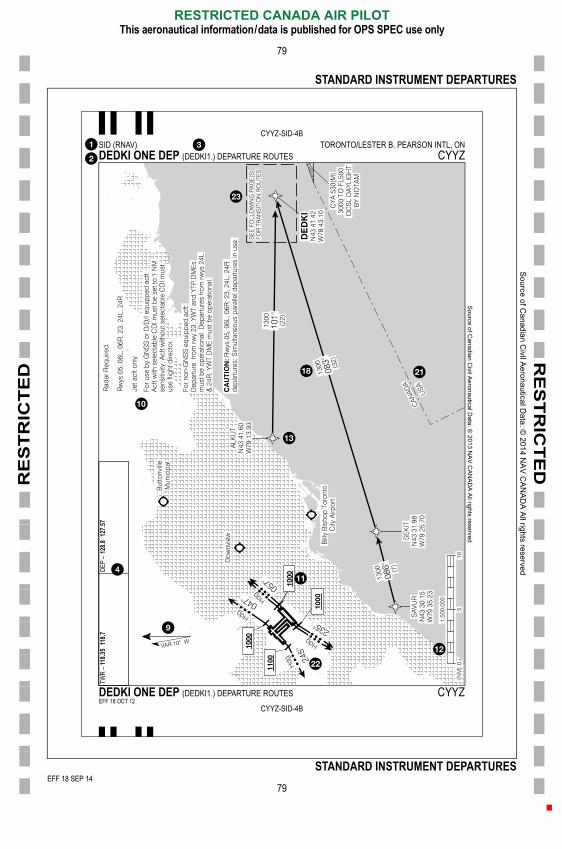
So
urce o
f Ca
nad
ian C
ivil Ae
rona
utical D
ata: ©
201
4 NA
V C
AN
AD
A A
ll rights rese
rved
EEF
1
RE
ST
RIC
TE
DR
ES
TR
ICT
ED
STANDARD INSTRUMENT DEPARTURES
79
Source of C
anadian Civil A
eronautical Data: ©
2013 NA
V C
AN
AD
A A
ll rights reserved
CYYZ-SID-4BSID (RNAV) TORONTO/LESTER B. PEARSON INTL, ONDEDKI ONE DEP (DEDKI1.) DEPARTURE ROUTES CYYZ
DEP
� 12
8.812
7.57
511
8.7
EFF 18 SEP 14
4-5254 comm cleanup
RESTRICTED CANADA AIR PILOTThis aeronautical information/data is published for OPS SPEC use only
79
STANDARD INSTRUMENT DEPARTURES
CYYZ-SID-4B
TWR
� 118
.3
DEDKI ONE DEP (DEDKI1.) DEPARTURE ROUTES CYYZEFF 18 OCT 12
FF 18 SEP 14F 6 FEB 14
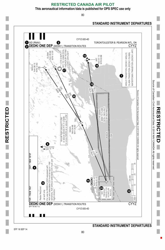
So
urce o
f Ca
nad
ian C
ivil Ae
rona
utical D
ata: ©
201
4 NA
V C
AN
AD
A A
ll rights rese
rved
EEF
1
RE
ST
RIC
TE
DR
ES
TR
ICT
ED
STANDARD INSTRUMENT DEPARTURES
80
Source of C
anadian Civil A
eronautical Data: ©
2013 NA
V C
AN
AD
A A
ll rights reserved
CYYZ-SID-4DSID (RNAV) TORONTO/LESTER B. PEARSON INTL, ONDEDKI ONE DEP (DEDKI1.) TRANSITION ROUTES CYYZ
DEP
� 12
8.812
7.57
511
8.7
EFF 18 SEP 14
4-5254 comm cleanup
RESTRICTED CANADA AIR PILOTThis aeronautical information/data is published for OPS SPEC use only
80
STANDARD INSTRUMENT DEPARTURES
CYYZ-SID-4D
TWR
� 118
.3
DEDKI ONE DEP (DEDKI1.) TRANSITION ROUTES CYYZEFF 18 OCT 12
FF 18 SEP 14F 6 FEB 14

So
urce o
f Ca
nad
ian C
ivil Ae
rona
utical D
ata: ©
201
4 NA
V C
AN
AD
A A
ll rights rese
rved
E
RE
ST
RIC
TE
DR
ES
TR
ICT
ED
STANDARD INSTRUMENT DEPARTURES
81
Pilot NAV SID
Source of C
anadian Civil Aeronautical D
ata: © 2013 N
AV
CA
NA
DA
All rights reserved
CYYJ-SID-2ASID (PILOT NAV) VICTORIA INTL, BCMILL BAY SEVEN DEP (MB7.) CYYJ
Departure Route Description
All rwys: Contact Victoria Terminal after passing 1000 unless instructed otherwise by ATC. Maintain 4000 or as assigned.
Rwy 27 � ½: Requires a minimum climb gradient of 380 ft/NM to 3200. Climb direct to �MB� NDB.
Rwy 31 � ½: Restricted to Cat A & B acft only. Requires a minimum climb gradient of 340 ft/NM to 3100. Climb hdg 315° to 740. Then climbing LEFT turn direct to �MB� NDB.
NOTE: Refer to noise abatement procedures for additional requirements.
Communication Failure
On recognition of failure proceed as follows:
1. Select transponder code 7600;
2. Maintain last assigned altitude until 10 minutes after take-off, then;
3. Climb to flight planned altitude.
DEPARTURE CLIMB RATE V/V (FPM)GROUND SPEED 90 120 140 160 180 200 250 300
340 FT/NM 510 680 800 910 1020 1140 1420 1700380 FT/NM 570 760 890 1020 1140 1270 1590 1900
DISCO TRANSITION:(MB7.DISCO)
Cross �MB� NDB. Then climbing LEFT turn hdg 102°, intercept OBD �YYJ� R-131 to DISCO.
VANCOUVER TRANSITION:(MB7.YVR)
Cross �MB� NDB. Then climbing RIGHT turn, intercept OBD track 304° from �MB� NDB. Cross �YVR� R-205, turn RIGHT intercept INBD R-210 to �YVR� VOR.
EFF 6 FEB 14
RESTRICTED CANADA AIR PILOTThis aeronautical information/data is published for OPS SPEC use only
81
STANDARD INSTRUMENT DEPARTURES
CYYJ-SID-2A
MILL BAY SEVEN DEP (MB7.) CYYJEFF 18 OCT 12
001/2014
FF 6 FEB 14

So
urce o
f Ca
nad
ian C
ivil Ae
rona
utical D
ata: ©
201
4 NA
V C
AN
AD
A A
ll rights rese
rved
E
RE
ST
RIC
TE
DR
ES
TR
ICT
ED
STANDARD INSTRUMENT DEPARTURES
82
Source of C
anadian Civil A
eronautical Data: ©
2013 NA
V C
AN
AD
A All rights reserved
CYYJ-SID-2BSID (PILOT NAV) VICTORIA INTL, BCMILL BAY SEVEN DEP (MB7.) CYYJ
TML �
133
.859.7
119.1
239.6
mloo
ps �
119.7
EFF 6 FEB 14
RESTRICTED CANADA AIR PILOTThis aeronautical information/data is published for OPS SPEC use only
82
STANDARD INSTRUMENT DEPARTURES
CYYJ-SID-2B
TWR
� 11
RADI
O Ka
MILL BAY SEVEN DEP (MB7.) CYYJEFF 18 OCT 12
001/2014
FF 6 FEB 14
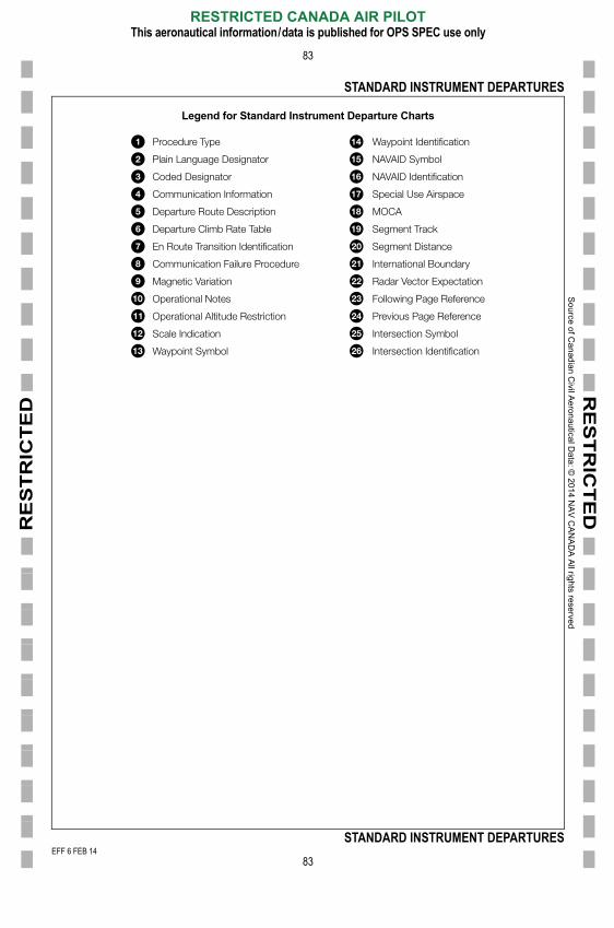
So
urce o
f Ca
nad
ian C
ivil Ae
rona
utical D
ata: ©
201
4 NA
V C
AN
AD
A A
ll rights rese
rved
E
RE
ST
RIC
TE
DR
ES
TR
ICT
ED
STANDARD INSTRUMENT DEPARTURES
83
Legend for Standard Instrument Departure Charts
Procedure Type
Plain Language Designator
Coded Designator
Communication Information
Departure Route Description
Departure Climb Rate Table
En Route Transition Identification
Communication Failure Procedure
Magnetic Variation
Operational Notes
Operational Altitude Restriction
Scale Indication
Waypoint Symbol
Waypoint Identification
NAVAID Symbol
NAVAID Identification
Special Use Airspace
MOCA
Segment Track
Segment Distance
International Boundary
Radar Vector Expectation
Following Page Reference
Previous Page Reference
Intersection Symbol
Intersection Identification
EFF 6 FEB 14
RESTRICTED CANADA AIR PILOTThis aeronautical information/data is published for OPS SPEC use only
83
STANDARD INSTRUMENT DEPARTURES
001/2014
FF 6 FEB 14
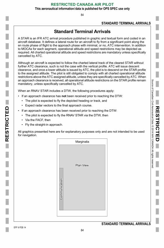
RE
ST
RIC
TE
D
Sou
rce of C
an
adia
n Civil A
eron
autica
l Data
: © 20
14 N
AV
CA
NA
DA
All righ
ts reserve
d
E
RE
ST
RIC
TE
D
84
STANDARD TERMINAL ARRIVALS
Standard Terminal ArrivalsA STAR is an IFR ATC arrival procedure published in graphic and textual form and coded in an aircraft database. It defines a lateral route for an aircraft to fly from a significant point along the en route phase of flight to the approach phase with minimal, or no, ATC intervention. In addition to MOCAs for each segment, operational altitude and speed restrictions may be depicted as required. All charted operational altitude and speed restrictions are mandatory unless specifically cancelled by ATC.
Although an aircraft is expected to follow the charted lateral track of the cleared STAR without further ATC clearance, such is not the case with the vertical profile. ATC will issue descent clearance, and once a lower altitude is issued by ATC, the pilot is to descend on the STAR profile to the assigned altitude. The pilot is still obligated to comply with all charted operational altitude restrictions above the ATC assigned altitude, unless they are specifically cancelled by ATC. When an approach clearance is received, all operational altitude restrictions on the STAR profile remain mandatory, unless specifically cancelled by ATC.
When an RNAV STAR includes a DTW, the following procedures apply:
• If an approach clearance has not been received prior to reaching the DTW:
• The pilot is expected to fly the depicted heading or track, and
• Expect radar vectors to the final approach course.
• If an approach clearance has been received prior to reaching the DTW:
• The pilot is expected to fly the RNAV STAR via the DTW, then
• Via the FACF, then
• Fly the straight-in approach.
All graphics presented here are for explanatory purposes only and are not intended to be used for navigation.
Marginalia
Plan View
unic
atio
n
EFF 6 FEB 14
RESTRICTED CANADA AIR PILOTThis aeronautical information/data is published for OPS SPEC use only
84
STANDARD TERMINAL ARRIVALS
Com
m
001/2014
FF 6 FEB 14

So
urce o
f Ca
nad
ian C
ivil Ae
rona
utical D
ata: ©
201
4 NA
V C
AN
AD
A A
ll rights rese
rved
E
RE
ST
RIC
TE
DR
ES
TR
ICT
ED
STANDARD TERMINAL ARRIVALS
85
Marginalia
Information shown in the periphery of the STAR chart includes the procedure identification, aerodrome identification, procedure effective date and chart number.
Procedure IdentificationThe procedure identification of a STAR chart includes the primary procedure identification and the enroute transition identification.
Primary Procedure IdentificationThe primary procedure identification consists of the following three elements:
• Procedure type
• Plain language designator
• Coded designator
Procedure TypeThe procedure type is shown as one of the following:
• STAR – identifies the procedure as a conventional STAR
CYYZ-STAR-7ASTAR (RNAV) TORONTO/LESTER B. PEARSON INTL, ONUDNOX ONE ARR (RAGID.UDNOX1) TRANSITION ROUTES CYYZ
CYYZ-STAR-7A
ATIS
� 12
0.
UDNOX ONE ARR (RAGID.UDNOX1) TRANSITION ROUTES CYYZEFF 18 OCT 12
Volume Bar
Procedure Type
Plain Language Designator
Coded Designator
Chart Content Indication
Chart Number
Aerodrome Name
Province/Territory
Aerodrome Identifier
Effective Date
EFF 6 FEB 14
RESTRICTED CANADA AIR PILOTThis aeronautical information/data is published for OPS SPEC use only
85
STANDARD TERMINAL ARRIVALS
• STAR (RNAV) – identifies the procedure as an RNAV STAR
001/2014
FF 6 FEB 14

So
urce o
f Ca
nad
ian C
ivil Ae
rona
utical D
ata: ©
201
4 NA
V C
AN
AD
A A
ll rights rese
rved
E
RE
ST
RIC
TE
DR
ES
TR
ICT
ED
STANDARD TERMINAL ARRIVALS
86
Plain Language DesignatorThe plain language designator is the spoken identification for the STAR procedure. It consists of a basic indicator, validity number and the term “ARR”. The validity number is a number between 1 and 9 assigned sequentially after a qualifying procedure amendment. A qualifying procedure amendment is a change in a procedure track or other significant change affecting the database coding of the procedure.
• HOPE NINE ARR
• UDNOX ONE ARR
Coded DesignatorThe coded designator is the database/flight planing identification for the STAR procedure. It consists of the identification of the first significant point of the STAR procedure’s common section followed by a coded version of the plain language basic indicator and the validity number.
• (HE.HE9)
• (RAGID.UDNOX1)
Similar to the procedure identifications for approach procedures, the primary procedure identification for STAR procedures may be suffixed with one or both of the following suffixes.
• “(TRUE)” Identifies the procedure as existing in NDA
• “(DND)” Identifies the procedure as a procedure designed and maintained by theDepartment of National Defence
Enroute Transition IdentificationWhen a STAR procedure includes transitions from the enroute airspace structure, the enroute transitions are identified in similar fashion to the main STAR procedure. The enroute transition identification includes a plain language designator and a coded designator. The plain language designator is the spoken identification for the enroute transition and is usually derived from the name of the first point of the enroute transition. The coded designator is the database/flight planning identification for the enroute transition and is derived from both the enroute transition plain language designator and the primary procedure identification.
• PHILIPSBURG TRANSITION: (PSB.LLEEO2)
• METOW TRANSITION: (METOW.GRIZZ3)
• TORNI TRANSITION: (TORNI.UDNOX1)
Plain Language Designator
Coded Designator
EFF 6 FEB 14
RESTRICTED CANADA AIR PILOTThis aeronautical information/data is published for OPS SPEC use only
86
STANDARD TERMINAL ARRIVALS
001/2014
FF 6 FEB 14
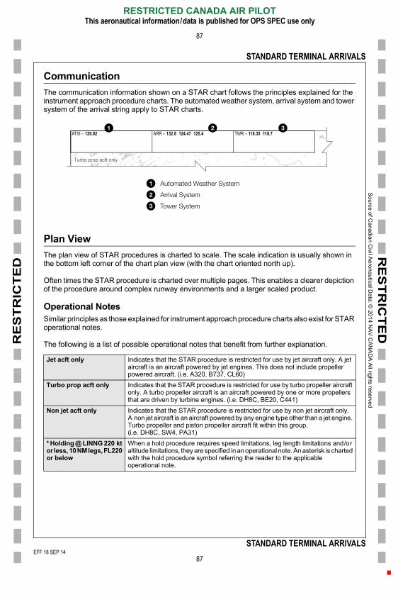
So
urce o
f Ca
nad
ian C
ivil Ae
rona
utical D
ata: ©
201
4 NA
V C
AN
AD
A A
ll rights rese
rved
EEF
RE
ST
RIC
TE
DR
ES
TR
ICT
ED
STANDARD TERMINAL ARRIVALS
87
Communication
The communication information shown on a STAR chart follows the principles explained for the instrument approach procedure charts. The automated weather system, arrival system and tower system of the arrival string apply to STAR charts.
Plan View
The plan view of STAR procedures is charted to scale. The scale indication is usually shown in the bottom left corner of the chart plan view (with the chart oriented north up).
Often times the STAR procedure is charted over multiple pages. This enables a clearer depiction of the procedure around complex runway environments and a larger scaled product.
Operational NotesSimilar principles as those explained for instrument approach procedure charts also exist for STAR operational notes.
The following is a list of possible operational notes that benefit from further explanation.
Jet acft only Indicates that the STAR procedure is restricted for use by jet aircraft only. A jet aircraft is an aircraft powered by jet engines. This does not include propeller powered aircraft. (i.e. A320, B737, CL60)
Turbo prop acft only Indicates that the STAR procedure is restricted for use by turbo propeller aircraft only. A turbo propeller aircraft is an aircraft powered by one or more propellers that are driven by turbine engines. (i.e. DH8C, BE20, C441)
Non jet acft only Indicates that the STAR procedure is restricted for use by non jet aircraft only. A non jet aircraft is an aircraft powered by any engine type other than a jet engine. Turbo propeller and piston propeller aircraft fit within this group.(i.e. DH8C, SW4, PA31)
* Holding @ LINNG 220 kt or less, 10 NM legs, FL220 or below
When a hold procedure requires speed limitations, leg length limitations and/or altitude limitations, they are specified in an operational note. An asterisk is charted with the hold procedure symbol referring the reader to the applicable
TWR � 118.35 118.7ARR � 132.8 124.47 125.4ATIS � 120.82
Automated Weather System
Arrival System
Tower System
EFF 18 SEP 14
RESTRICTED CANADA AIR PILOTThis aeronautical information/data is published for OPS SPEC use only
87
STANDARD TERMINAL ARRIVALS
operational note.
FF 18 SEP 14F 6 FEB 14

So
urce o
f Ca
nad
ian C
ivil Ae
rona
utical D
ata: ©
201
4 NA
V C
AN
AD
A A
ll rights rese
rved
EEF
RE
ST
RIC
TE
DR
ES
TR
ICT
ED
STANDARD TERMINAL ARRIVALS
88
RNAV STAR
Source of C
anadian Civil Aeronautical D
ata: © 2013 N
AV
CA
NA
DA
All rights reserved
CYYZ-STAR-7ASTAR (RNAV) TORONTO/LESTER B. PEARSON INTL, ONUDNOX ONE ARR (RAGID.UDNOX1) TRANSITION ROUTES CYYZ
TWR
� 118
.3511
8.7AR
R �
132.8
124.4
712
5.4
EFF 18 SEP 14
RESTRICTED CANADA AIR PILOTThis aeronautical information/data is published for OPS SPEC use only
88
STANDARD TERMINAL ARRIVALS
CYYZ-STAR-7A
ATIS
� 12
0.82
UDNOX ONE ARR (RAGID.UDNOX1) TRANSITION ROUTES CYYZEFF 18 OCT 12
FF 18 SEP 14F 6 FEB 14
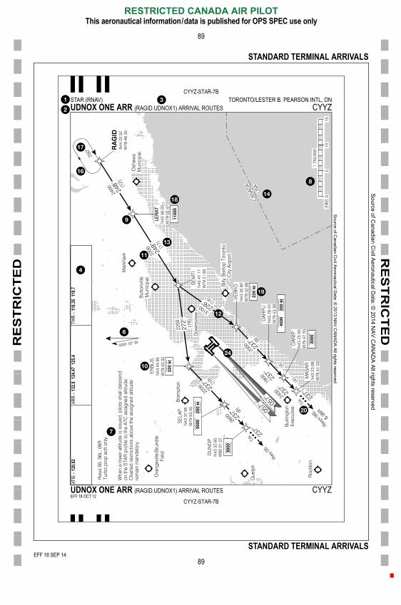
So
urce o
f Ca
nad
ian C
ivil Ae
rona
utical D
ata: ©
201
4 NA
V C
AN
AD
A A
ll rights rese
rved
EEF
RE
ST
RIC
TE
DR
ES
TR
ICT
ED
STANDARD TERMINAL ARRIVALS
89
Source of C
anadian Civil Aeronautical D
ata: © 2013 N
AV
CA
NA
DA
All rights reserved
CYYZ-STAR-7BSTAR (RNAV) TORONTO/LESTER B. PEARSON INTL, ONUDNOX ONE ARR (RAGID.UDNOX1) ARRIVAL ROUTES CYYZ
TWR
� 118
.3511
8.7AR
R �
132.8
124.4
712
5.4.82
EFF 18 SEP 14
14-5254 comm cleanup
RESTRICTED CANADA AIR PILOTThis aeronautical information/data is published for OPS SPEC use only
89
STANDARD TERMINAL ARRIVALS
CYYZ-STAR-7B
ATIS
� 12
0
UDNOX ONE ARR (RAGID.UDNOX1) ARRIVAL ROUTES CYYZEFF 18 OCT 12
FF 18 SEP 14F 6 FEB 14

So
urce o
f Ca
nad
ian C
ivil Ae
rona
utical D
ata: ©
201
4 NA
V C
AN
AD
A A
ll rights rese
rved
E
RE
ST
RIC
TE
DR
ES
TR
ICT
ED
STANDARD TERMINAL ARRIVALS
90
RNAV STAR (with DTW and FACF)
Source of C
anadian Civil Aeronautical D
ata: © 2013 N
AV
CA
NA
DA
All rights reserved
CYUL-STAR-3BSTAR (RNAV) MONTRÉAL/PIERRE-ELLIOTT-TRUDEAU INTL, QCHABBS ONE ARR (HABBS.HABBS1) ARRIVAL ROUTES CYUL
TWR
� 119
.926
7.1AR
R �
118.9
124.6
512
6.913
2.85
268.3
En)
127.5
(Fr)
EFF 6 FEB 14
RESTRICTED CANADA AIR PILOTThis aeronautical information/data is published for OPS SPEC use only
90
STANDARD TERMINAL ARRIVALS
CYUL-STAR-3B
ATIS
� 13
3.7 (
HABBS ONE ARR (HABBS.HABBS1) ARRIVAL ROUTES CYULEFF 18 OCT 12
001/2014
FF 6 FEB 14

So
urce o
f Ca
nad
ian C
ivil Ae
rona
utical D
ata: ©
201
4 NA
V C
AN
AD
A A
ll rights rese
rved
EEF
1
RE
ST
RIC
TE
DR
ES
TR
ICT
ED
STANDARD TERMINAL ARRIVALS
91
Conventional STAR
Source of C
anadian Civil Aeronautical D
ata: © 2013 N
AV
CA
NA
DA
All rights reserved
CYVR-STAR-3BSTAR VANCOUVER INTL, BCCASDY NINE ARR (CASDY.CASDY9) ARRIVAL ROUTES CYVR
TWR
� 119
.55 (N
)11
8.7 (S
)22
6.5AR
R �
128.6
133.1
134.2
235
2.7
EFF 18 SEP 14
4-5254 comm cleanup
RESTRICTED CANADA AIR PILOTThis aeronautical information/data is published for OPS SPEC use only
91
STANDARD TERMINAL ARRIVALS
CYVR-STAR-3B
ATIS
� 12
4.6
CASDY NINE ARR (CASDY.CASDY9) ARRIVAL ROUTES CYVREFF 18 OCT 12
FF 18 SEP 14F 6 FEB 14

So
urce o
f Ca
nad
ian C
ivil Ae
rona
utical D
ata: ©
201
4 NA
V C
AN
AD
A A
ll rights rese
rved
E
RE
ST
RIC
TE
DR
ES
TR
ICT
ED
STANDARD TERMINAL ARRIVALS
92
Legend for Standard Terminal Arrival Charts
Procedure Type
Plain Language Designator
Coded Designator
Communication Information
En Route Transition Identification
Magnetic Variation
Operational Notes
Scale Indication
Waypoint Symbol
Waypoint Identification
MOCA
Segment Track
Segment Distance
International Boundary
Following Page Reference
Hold Pattern
Hold Inbound Track
Operational Altitude Restriction
Operational Speed Restriction
Radar Vector Expectation
Downwind Termination Waypoint
Final Approach Course Fix
Special Use Airspace
Localizer Front Course
RNAV Approach Reference
NAVAID Symbol
NAVAID Identification
Operational Altitude to Expect
Intersection Symbol
Intersection Identification
EFF 6 FEB 14
RESTRICTED CANADA AIR PILOTThis aeronautical information/data is published for OPS SPEC use only
92
STANDARD TERMINAL ARRIVALS
001/2014
FF 6 FEB 14
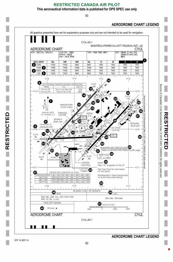
RE
ST
RIC
TE
D
Sou
rce of C
an
adia
n Civil A
eron
autica
l Data
: © 20
14 N
AV
CA
NA
DA
All righ
ts reserve
d
EEF
RE
ST
RIC
TE
D
93
AERODROME CHART LEGEND
All graphics presented here are for explanatory purposes only and are not intended to be used for navigation.
Source of C
anadian Civil A
eronautical Data: ©
2013 NA
V C
AN
AD
A A
ll rights reserved
CYUL-AD-1MONTRÉAL/PIERRE-ELLIOTT-TRUDEAU INTL, QC
AERODROME CHART CYULATIS � 133.7 (En) 127.5 (Fr) CLNC DEL � 125.6
APRON � 122.07GND � 121.9 275.8
TWR � 119.9 124.3 267.1 DEP � 120.42 (S) (SE) (SW)124.65 (W) (NW) (NE)268.3
DECL DISTS 06L 24R 06R 24L 10 28 10 28TORA 11000 11000 9600 9600 7000 7000 7000 7000TODA 11984 11984 10584 10584 7984 7984 7984 7984ASDA 11000 11000 9600 9600 7000 7000 6000 6000LDA 11000 11000 9600 9600 7000 7000 7000 7000
EFF 18 SEP 14
RESTRICTED CANADA AIR PILOTThis aeronautical information/data is published for OPS SPEC use only
93
AERODROME CHART LEGEND
CYUL-AD-1
AERODROME CHART CYUL
FF 18 SEP 14F 6 FEB 14

So
urce o
f Ca
nad
ian C
ivil Ae
rona
utical D
ata: ©
201
4 NA
V C
AN
AD
A A
ll rights rese
rved
E
RE
ST
RIC
TE
DR
ES
TR
ICT
ED
AERODROME CHART LEGEND
94
Aerodrome Chart Legend
Declared Distance Night
Take Off Run Available
Take Off Distance Available
Accelerate Stop Distance Available
Landing Distance Available
Landing Distance Available Table
Magnetic Variation
Latitude Coordinate
Threshold Displacement Note
Visual Glide Slope Indicator
Displaced Runway Threshold
Turnaround Bay
Centreline Light
Runway Bearing
RVR Sensor
Approach Lighting
Wind Direction Indicator
Taxiway
Taxiway Identification
Aerodrome Geometric Centre Coordinate
Runway Dimensions
Obstruction
Building
Threshold Elevation
Runway Number
CAT I Holding Bar
Apron Identification
Runway
Departure Procedure
Runway Slope Gradient
NAVAID within AD Limit
NAVAID Check Point
Operational Notes
Control Tower
Longitude Coordinate
Construction Area
Departure Climb Rate Table
Reduced Visibility Operation Table
Low Visibility Operation Table
Take-off Minima Box
Scale Bar
Geographic Grid
EFF 6 FEB 14
RESTRICTED CANADA AIR PILOTThis aeronautical information/data is published for OPS SPEC use only
94
AERODROME CHART LEGEND
001/2014
FF 6 FEB 14
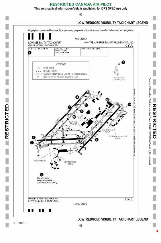
RE
ST
RIC
TE
D
Sou
rce of C
an
adia
n Civil A
eron
autica
l Data
: © 20
14 N
AV
CA
NA
DA
All righ
ts reserve
d
EEF
RE
ST
RIC
TE
D
95
LOW/REDUCED VISIBILITY TAXI CHART LEGEND
All graphics presented here are for explanatory purposes only and are not intended to be used for navigation.
Source of C
anadian Civil A
eronautical Data: ©
2013 NA
V C
AN
AD
A A
ll rights reserved
CYUL-GM-3CLOW VISIBILITY TAXI CHART MONTRÉAL/PIERRE-ELLIOTT-TRUDEAU INTL, QC(RVR LESS THAN 1200 TO 600 FT) CYULATIS � 133.7 (En) 127.5 (Fr) CLNC DEL � 125.6
APRON � 122.07GND � 121.9 275.8
TWR � 119.9 124.3 267.1
EFF 18 SEP 14
RESTRICTED CANADA AIR PILOTThis aeronautical information/data is published for OPS SPEC use only
95
LOW/REDUCED VISIBILITY TAXI CHART LEGEND
CYUL-GM-3C
(RVR LESS THAN 1200 TO 600 FT) CYULLOW VISIBILITY TAXI CHART
FF 18 SEP 14F 6 FEB 14
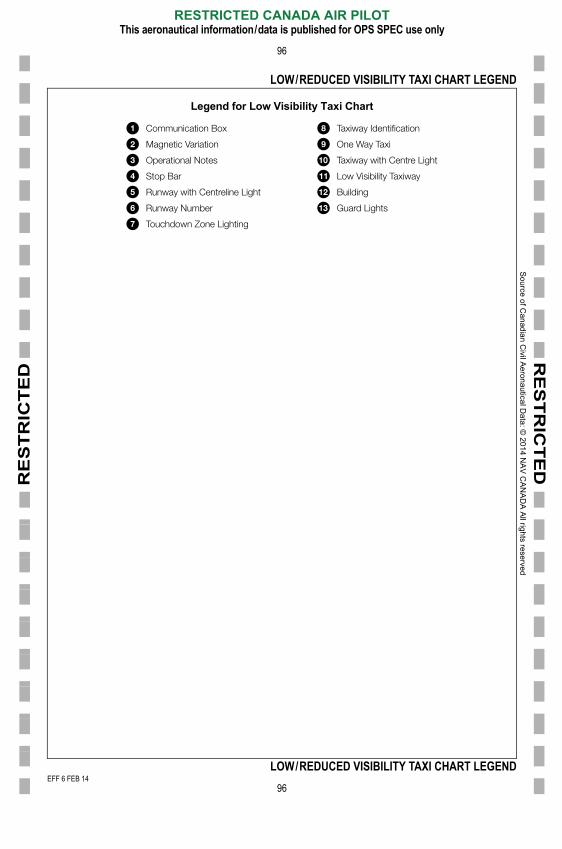
So
urce o
f Ca
nad
ian C
ivil Ae
rona
utical D
ata: ©
201
4 NA
V C
AN
AD
A A
ll rights rese
rved
E
RE
ST
RIC
TE
DR
ES
TR
ICT
ED
LOW/REDUCED VISIBILITY TAXI CHART LEGEND
96
Legend for Low Visibility Taxi Chart
Communication Box
Magnetic Variation
Operational Notes
Stop Bar
Runway with Centreline Light
Runway Number
Touchdown Zone Lighting
Taxiway Identification
One Way Taxi
Taxiway with Centre Light
Low Visibility Taxiway
Building
Guard Lights
EFF 6 FEB 14
RESTRICTED CANADA AIR PILOTThis aeronautical information/data is published for OPS SPEC use only
96
LOW/REDUCED VISIBILITY TAXI CHART LEGEND
001/2014
FF 6 FEB 14
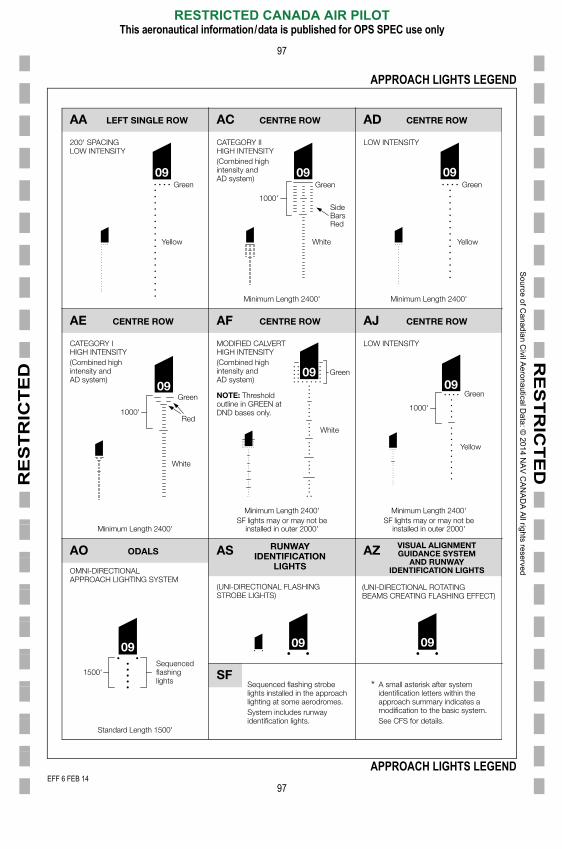
RE
ST
RIC
TE
D
Sou
rce of C
an
adia
n Civil A
eron
autica
l Data
: © 20
14 N
AV
CA
NA
DA
All righ
ts reserve
d
E
RE
ST
RIC
TE
D
97
APPROACH LIGHTS LEGEND
0909
09
09 09 09
09 09
09
LEFT SINGLE ROWAA CENTRE ROWAC CENTRE ROWAD
CENTRE ROWAE
ODALSAO RUNWAYIDENTIFICATION
LIGHTS
AS VISUAL ALIGNMENTGUIDANCE SYSTEM
AND RUNWAYIDENTIFICATION LIGHTS
AZ
CENTRE ROWAF CENTRE ROWAJ
200' SPACINGLOW INTENSITY
LOW INTENSITY
LOW INTENSITY
CATEGORY IIHIGH INTENSITY(Combined highintensity and AD system)
CATEGORY IHIGH INTENSITY(Combined highintensity and AD system)
MODIFIED CALVERTHIGH INTENSITY(Combined highintensity and AD system)
(UNI-DIRECTIONAL FLASHINGSTROBE LIGHTS)
(UNI-DIRECTIONAL ROTATINGBEAMS CREATING FLASHING EFFECT)
OMNI-DIRECTIONALAPPROACH LIGHTING SYSTEM
NOTE: Thresholdoutline in GREEN atDND bases only.
Green Green Green
Yellow Yellow
GreenGreen
Green
Red
Yellow
White
White
White
SideBarsRed
1000'
1000' 1000'
Minimum Length 2400'
Minimum Length 2400'
Minimum Length 2400'SF lights may or may not be
installed in outer 2000'
Minimum Length 2400'SF lights may or may not be
installed in outer 2000'
Minimum Length 2400'
EFF 6 FEB 14
RESTRICTED CANADA AIR PILOTThis aeronautical information/data is published for OPS SPEC use only
97
APPROACH LIGHTS LEGEND
SFSequenced flashing strobelights installed in the approachlighting at some aerodromes.System includes runwayidentification lights.
A small asterisk after systemidentification letters within theapproach summary indicates amodification to the basic system.See CFS for details.
*
Sequencedflashinglights
1500'
Standard Length 1500'
001/2014
FF 6 FEB 14
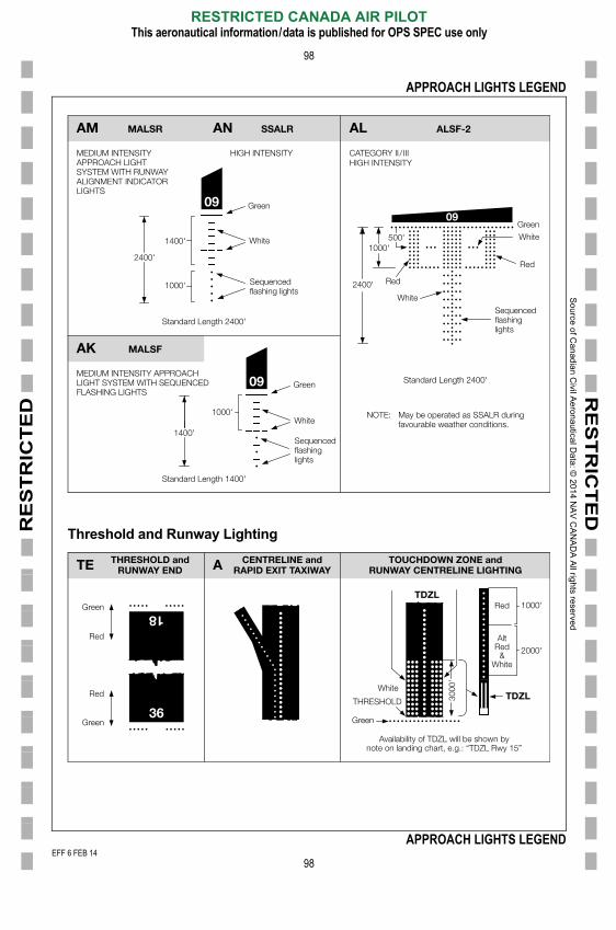
So
urce o
f Ca
nad
ian C
ivil Ae
rona
utical D
ata: ©
201
4 NA
V C
AN
AD
A A
ll rights rese
rved
E
RE
ST
RIC
TE
DR
ES
TR
ICT
ED
APPROACH LIGHTS LEGEND
98
Threshold and Runway Lighting
09
09
09
MALSRAM SSALRAN ALSF-2AL
MALSFAK
MEDIUM INTENSITYAPPROACH LIGHTSYSTEM WITH RUNWAYALIGNMENT INDICATORLIGHTS
CATEGORY II / IIIHIGH INTENSITY
HIGH INTENSITY
MEDIUM INTENSITY APPROACHLIGHT SYSTEM WITH SEQUENCEDFLASHING LIGHTS
NOTE: May be operated as SSALR during favourable weather conditions.
Green
Red
Red
White
Green
Green
White
WhiteWhite
Sequencedflashing lights
Sequencedflashinglights
Sequencedflashinglights
1000'
1000'500'1400'
2400'
2400'
1000'
1400'
Standard Length 2400'
Standard Length 1400'
Standard Length 2400'
18
THRESHOLD andRUNWAY ENDTE CENTRELINE and
RAPID EXIT TAXIWAYTOUCHDOWN ZONE and
RUNWAY CENTRELINE LIGHTING
TDZL
TDZL
A
White
Red
AltRed
&White
THRESHOLD
Green
Red
Red
1000'
3000
'
2000'
EFF 6 FEB 14
RESTRICTED CANADA AIR PILOTThis aeronautical information/data is published for OPS SPEC use only
98
APPROACH LIGHTS LEGEND
36GreenGreen
Availability of TDZL will be shown bynote on landing chart, e.g.: “TDZL Rwy 15”
001/2014
FF 6 FEB 14
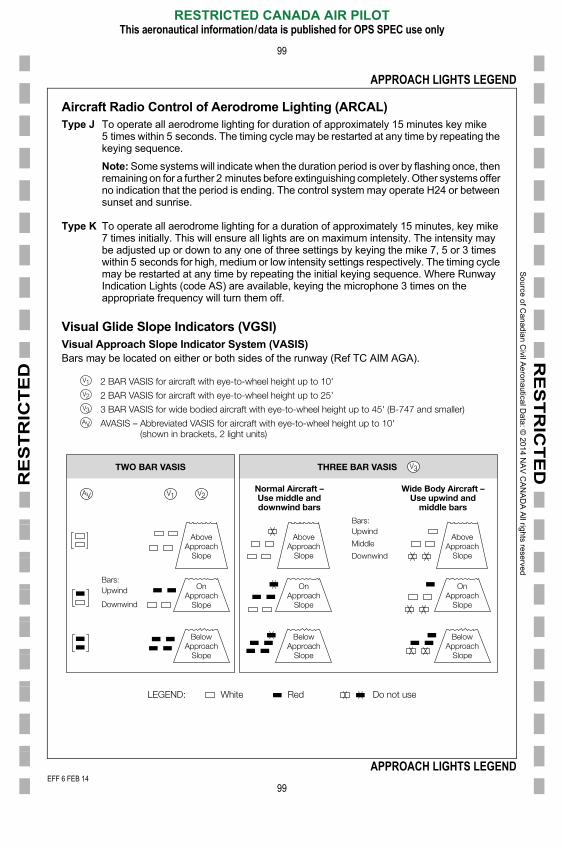
So
urce o
f Ca
nad
ian C
ivil Ae
rona
utical D
ata: ©
201
4 NA
V C
AN
AD
A A
ll rights rese
rved
E
RE
ST
RIC
TE
DR
ES
TR
ICT
ED
APPROACH LIGHTS LEGEND
99
Aircraft Radio Control of Aerodrome Lighting (ARCAL)Type J To operate all aerodrome lighting for duration of approximately 15 minutes key mike
5 times within 5 seconds. The timing cycle may be restarted at any time by repeating the keying sequence.
Note: Some systems will indicate when the duration period is over by flashing once, then remaining on for a further 2 minutes before extinguishing completely. Other systems offer no indication that the period is ending. The control system may operate H24 or between sunset and sunrise.
Type K To operate all aerodrome lighting for a duration of approximately 15 minutes, key mike 7 times initially. This will ensure all lights are on maximum intensity. The intensity may be adjusted up or down to any one of three settings by keying the mike 7, 5 or 3 times within 5 seconds for high, medium or low intensity settings respectively. The timing cycle may be restarted at any time by repeating the initial keying sequence. Where Runway Indication Lights (code AS) are available, keying the microphone 3 times on the appropriate frequency will turn them off.
Visual Glide Slope Indicators (VGSI)Visual Approach Slope Indicator System (VASIS)Bars may be located on either or both sides of the runway (Ref TC AIM AGA).
2 BAR VASIS for aircraft with eye-to-wheel height up to 10'
2 BAR VASIS for aircraft with eye-to-wheel height up to 25'
3 BAR VASIS for wide bodied aircraft with eye-to-wheel height up to 45' (B-747 and smaller)
AVASIS – Abbreviated VASIS for aircraft with eye-to-wheel height up to 10' (shown in brackets, 2 light units)
Bars:Upwind
Downwind
AboveApproach
Slope
OnApproach
Slope
BelowApproach
AboveApproach
Slope
OnApproach
Slope
BelowApproach
AboveApproach
Slope
OnApproach
Slope
BelowApproach
Bars:Upwind
Middle
Downwind
Normal Aircraft –Use middle anddownwind bars
Wide Body Aircraft –Use upwind and
middle bars
TWO BAR VASIS THREE BAR VASIS
EFF 6 FEB 14
RESTRICTED CANADA AIR PILOTThis aeronautical information/data is published for OPS SPEC use only
99
APPROACH LIGHTS LEGEND
LEGEND: White Red Do not use
SlopeSlopeSlope
001/2014
FF 6 FEB 14
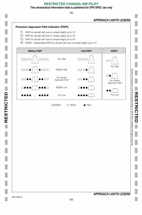
So
urce o
f Ca
nad
ian C
ivil Ae
rona
utical D
ata: ©
201
4 NA
V C
AN
AD
A A
ll rights rese
rved
E
RE
ST
RIC
TE
DR
ES
TR
ICT
ED
APPROACH LIGHTS LEGEND
100
Precision Approach Path Indicator (PAPI)
PAPI for aircraft with eye-to-wheel height up to 10'
PAPI for aircraft with eye-to-wheel height up to 25'
PAPI for aircraft with eye-to-wheel height up to 45'
APAPI – Abbreviated PAPI for aircraft with eye-to-wheel height up to 10'
LEGEND: White Red
Too High
Too High
Slightly High
On CorrectApproach Path
Slightly Low
Too Low Too Low
On CorrectApproach Path
Military PAPI Civil PAPI APAPI
EFF 6 FEB 14
RESTRICTED CANADA AIR PILOTThis aeronautical information/data is published for OPS SPEC use only
100
APPROACH LIGHTS LEGEND
001/2014
FF 6 FEB 14
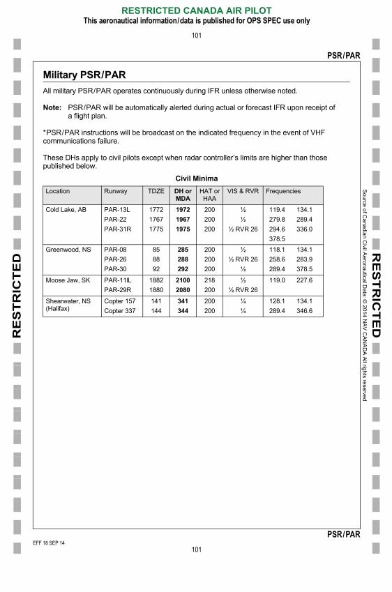
RE
ST
RIC
TE
D
Sou
rce of C
an
adia
n Civil A
eron
autica
l Data
: © 20
14 N
AV
CA
NA
DA
All righ
ts reserve
d
EEF
RE
ST
RIC
TE
D
101
PSR/PAR
Military PSR/PAR
All military PSR/PAR operates continuously during IFR unless otherwise noted.
Note: PSR/PAR will be automatically alerted during actual or forecast IFR upon receipt of a flight plan.
*PSR/PAR instructions will be broadcast on the indicated frequency in the event of VHF communications failure.
These DHs apply to civil pilots except when radar controller’s limits are higher than those published below.
Civil Minima
Location Runway TDZE DH orMDA
HAT orHAA
VIS & RVR Frequencies
Cold Lake, AB PAR-13L
PAR-22
PAR-31R
1772
1767
1775
1972
1967
1975
200
200
200
½
½
½ RVR 26
119.4 134.1
279.8 289.4
294.6 336.0
378.5
Greenwood, NS PAR-08
PAR-26
PAR-30
85
88
92
285
288
292
200
200
200
½
½ RVR 26
½
118.1 134.1
258.6 283.9
289.4 378.5
Moose Jaw, SK PAR-11lL
PAR-29R
1882
1880
2100
2080
218
200
½
½ RVR 26
119.0 227.6
Shearwater, NS (Halifax)
Copter 157
Copter 337
141
144
341
344
200
200
¼
¼
128.1 134.1
289.4 346.6
EFF 18 SEP 14
RESTRICTED CANADA AIR PILOTThis aeronautical information/data is published for OPS SPEC use only
101
PSR/PARFF 18 SEP 14
F 6 FEB 14