Embed Size (px)
Citation preview

AIN'T
By Richard F. Chandler, SupervisorProtection and Survival LabCivil Aeromedical Institute
Mike Monroney Aeronautical CenterP. O. Box 25082
Oklahoma City, OK 73125
Introduction
± HE MAIN PURPOSE of this arti-cle is to acquaint you with a few ofthe basic design concerns regardingrestraint systems so that you will beable to understand the design, to in-stall or to evaluate a system withsome knowledge of its function andits possible malfunctions. Particularemphasis will be on systems suitablefor crew restraint, but the generalconcepts will be applicable to passen-ger restraints as well. Before we getstarted, it would probably be of someuse to review just why restraint sys-tems were introduced in aircraft. Thelap belt (or seat belt, whichever youprefer), has been the traditional basicrestraint system in aircraft for manyyears. Its purpose is to keep the occu-pant closely attached to the seat dur-ing all the operational phases of theaircraft flight. It doesn't take muchimagination to visualize the problemsof trying to keep control of an aircraftflying through turbulence if the pilotdoesn't have his seat belt on ... and,for such obvious reasons, most pilotsreadily accept the need to wear thelap belt. Unfortunately, upper torsorestraints (shoulder belts) are as-sociated with a relatively rare occur-rence in the operation of an aircraft,and an unpleasant one at that, theaircraft crash. Most pilots, being typ-ical human beings, don't like to thinkof unpleasant things, particularly ifthey are related to flying, and so don'tthink too much of torso restraint sys-tems. Besides, we hear that they arehot, uncomfortable, a real mess to puton, interfere with the pleasure of fly-ing, etc., etc. All these excuses shouldbecome insignificant to the rationalpilot who understands that the proper
use of a correctly designed and in-stalled upper torso restraint couldmean the difference between ahealthy productive life or death orirreversible injury should that rela-tively rare occurrence spoil the plea-sure of flying.
Pelvic Restraint SystemsLet's look at the action of the lap
belt during a crash (see Figure la).Typically, the crash forces tend tomove the aircraft occupant down, for-ward and maybe to the side relativeto the aircraft interior. If the crashdeceleration is much above three orfour Gs, even the most healthy occu-pant won't be able to resist theseforces with his own strength. His bodywill pivot about the seat belt (this iscalled flailing) until it is stopped byhitting something inside the aircraft.Usually, the head and face violentlyhit the instrument panel, causing thehead to rotate backwards on the neckas the torso goes forward until it toois stopped by impacting the controlyoke. It's not the place of this articleto describe the injuries which result.You can use your own imagination,or can consult any number of goodreports on crash investigation (c.f.References 1 and 2).
It should be obvious that some formof upper torso restraint would im-prove this situation. But before wediscuss the upper torso restraint, letus consider some other problemswhich might occur with a lap belt ina crash, since lap belts are found inall aircraft restraint systems. Re-straint system design looks simple,but it is actually fairly involved, withmany factors begging consideration.Computer programs which considermost of these factors have been de-veloped to aid the restraint systemdesigner so that compromises in de-sign can be effective (References 3and 4). But if the designer doesn'thave access to these programs, he (orshe) best follow certain "rules ofthumb" which will yield a high prob-ability of a good design.
One of these rules has already beenillustrated in Figure la. The lap belt
generally performs best if it acts at anangle of about 45° with the aircraftlongitudinal axis. If the lap belt isinstalled so that it acts along a shal-low angle, as in Figure Ib, it is likelyto slip off the skeletal pelvis of theoccupant, and apply loads to the abdo-men. This is called "submarining". Ina severe crash these loads will be highenough to cause injury to internal or-gans, a potentially life threateningsituation. The flailing that results asthe pelvis rotates under the belt andthe upper torso rotates over the lapbelt will also cause bending of thelower (lumbar) spinal column. Thevertical crash loads will be transmit-ted through the bent spinal column,creating high stress in the front por-tion of the vertebrae which have beenbrought together by the flailing ac-tion. The injury which may result,called an "anterior wedge fracture ofthe lumbar vertebra", may heal with-out serious impairment, but any in-jury to the spinal column runs therisk of involving damage to the spinalcord. Spinal cord injury is the majorcause of paralysis resulting fromcrashes.
If the lap belt is installed at toosteep an angle, as in Figure Ic, it willbe ineffective in resisting forwardmovement of the occupant. Such in-stallations may result from rearwardadjustment of the seat along its tracksby a long legged occupant (when thebelt is anchored to the floor), or froman attempt to keep the belt out of thepassageway or foot space of an aftseated occupant. Since the belt cancarry only tension loads, it will allowthe occupant to move forward untilthe belt is reoriented so that the ten-sion load in the belt generates anadequate longitudinal component toresist further forward movement. Un-fortunately, by this time the occupantmay either have his knees in the in-strument panel (knee or femur in-jury), or be so far forward in the seatthat he slips off the front edge, allow-ing the belt angle to become shallowwith all the injury potentials dis-cussed in the previous paragraph.
This is a good place to point out twoother factors in restraint system de-
SPORT AVIATION 35
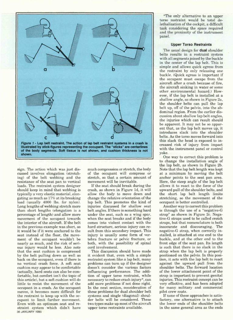
Figure 1 - Lap belt restraint. The action of lap belt restraint systems in a crash isillustrated by stick-figures representing the occupant. The "sticks" are centerlinesof the body segments. Soft tissue is not shown, and cushion thickness is notshown.
sign. The action which was just dis-cussed involves elongation (stretch-ing) of the belt webbing and theresistance of the seat pan to verticalloads. The restraint system designershould keep in mind that webbing istypically a very elastic material, elon-gating as much as 17% at its breakingload (usually 4000 Ibs. for nylon).Long lengths of webbing stretch morethan short lengths (elongation is apercentage of length) and allow moremovement of the occupant towardsthe interior of the aircraft. If the beltin the previous example was short, asit would be if it were anchored to theseat instead of the floor, the move-ment of the occupant wouldn't benearly as much, and the risk of seri-ous injury would be less. Also notethat the seat cushion is compressedby the belt pulling down as well asback on the occupant, even if there isno vertical crash force. A soft seatcushion may appear to be comfortable(actually, hard seats can also be com-fortable, but comfort isn't the topic ofthis article), but a soft cushion will dolittle to resist the movement of theoccupant in a crash. As the occupantmoves, it becomes more difficult forthe restraint to keep up with the oc-cupant to limit further movement.Even with an optimum seat and re-straint system which didn't have36 JANUARY 1985
much compression or stretch, the bodyof the occupant will compress orstretch, so that a certain amount ofmovement will be inevitable.
If the seat should break during thecrash, as shown in Figure Id, it willallow the body to move down andchange the relative orientation of thelap belt. This promotes the kind ofinjuries discussed for shallow seatbelt angles. If there is something hardunder the seat, such as a wing spar,when the seat breaks and if the bodycomes into violent contact with thehard structure, serious injury can re-sult from this secondary impact. Thisinjury is usually some form of ver-tebra fracture or pelvic fracture, orboth, with the possibility of spinalcord involvement.
This discussion should have madeit evident that, even with a simplerestraint system like a lap belt, manyproblems can turn up if the designerdoesn't consider the various factorsinfluencing performance. The addi-tion of upper torso restraint, whilenecessary to reduce crash injury*, canadd more problems if not done right.In the next section, consideration ofthese problems for dual shoulder beltsystems and single (diagonal) shoul-der belts will be considered. Thesetwo types make up most of the aircraftupper torso restraints available.
*The only alternative to an uppertorso restraint would be total de-lethalization of the cockpit, a difficulttask considering the space requiredand the proximity of the instrumentpanel.
Upper Torso RestraintsThe usual design for dual shoulder
belts results in a restraint systemwith all segments joined by the bucklein the center of the lap belt. This issimple and allows quick egress fromthe restraint by only releasing onebuckle. (Quick egress is important ifthe occupant must escape from theaircraft after a crash because of fire,the aircraft sinking in water or someother environmental hazard.) How-ever, if the lap belt is installed at ashallow angle, as shown in Figure 2a,the shoulder belts can pull the lapbelt up, off of the pelvis, into the ab-dominal region. From the earlier dis-cussion about shallow lap belt angles,the injuries which can result shouldbe apparent. It may not be so appar-ent that, as the lap belt moves up, itintroduces slack into the shoulderbelts. As the torso moves forward intothis slack the head is exposed to in-creased risk of injury from impactwith the instrument panel or controlyoke.
One way to correct this problem isto change the installation angle ofthe lap belt, as shown in Figure 2b.Note that the lap belt length was keptat a minimum by moving the beltanchor points to the seat pan area.Here, the steep angle of the lap beltallows it to react to the force of theupward pull of the shoulder belts, andthe short lap belt length limitsstretching, so the movement of theoccupant is better controlled.
Another way to correct this problemis through the use of a "negative-Gstrap" as shown in Figure 2c. Nega-tive-G straps used to be called crotchstraps, but that nomenclature is bothinaccurate and discouraging. Thenegative-G strap, when correctly in-stalled, is attached at one end to thebuckle, and at the other end to thefront edge of the seat pan. Its lengthis such that there is no slack in thestrap when the lap belt is properlypositioned on the pelvis. In this posi-tion, it acts with the lap belt to reactagainst the upward pull from theshoulder belts. The forward locationof the lower attachment point of thestrap is important to prevent genitalinjuries. This restraint concept can bevery effective, and has been adoptedfor many military and commercialpilot crew seats.
If none of these approaches is satis-factory, one alternative is to attachthe lower ends of the shoulder beltsin the same general area as the ends
of the lap belts, as shown in Figure2d. With this installation, the lap beltdoes not carry any load from theshoulder belts, and is more likely toremain on the pelvis during a crash.However, releasing the buckle on thelap belt does not release the shoulderbelts. If the upper ends of the shoulderbelts are attached to the aircraftthrough an emergency locking retrac-tor (commonly called an inertia reel,and used with the shoulder belts toallow movement of the occupant dur-ing normal flight, to increase comfort,and to stow the belts when not inuse), and if that retractor automat-ically unlocks the belts after thecrash, this may not present a seriousegress problem. The shoulder beltscan be slipped off just as if taking offa jacket. The emergency locking re-tractor will also solve the problem ofshoulder belt length adjustment thatexists with this type of installation.Without a retractor, this system canstill be used, but with more difficulty(see Reference 5). In this case, bothshoulder belts are furnished withmanual adjusters which allow the re-straint to be fitted to the occupant.Each lower end of the dual shoulderbelt passes through a slot in the cor-responding lap belt attachmenthardware (end fitting), and is thenstitched to the lap belt, near the buck-le. During the crash, tension in theshoulder belt segments is reflectedthrough the lap belt end fittings andthen to the lap belt and buckle. Whenthe buckle is opened for egress, thelap belt no longer holds tension on thelower ends of the shoulder belts. Theycan be pulled through the slots in thelap belt end fittings until the stitchedarea is reached. This allows slack inthe shoulder belts so they can beslipped off the shoulders. While notas easy as in some of the other de-signs, egress can still be fairly rapid.
The dual shoulder belts which havebeen discussed are generally thoughtto give better crash protection thansingle diagonal belts. The dual beltsdistribute the load over a larger areaof the body so contact pressure islower and their symmetric naturemeans that the body is held moresymmetrically, with less tendency totwist. They also provide more consist-ent restraint for crashes involving lat-eral forces. However, it is often impos-sible to find suitable structure behindthe occupant to attach the upper endof a dual belt system. Diagonal shoul-der belts have been used in auto-mobiles for a number of years, andthe crash experience which has re-sulted indicates that they performsurprisingly well (see, for example,Reference 6 and 7). Most automobilerestraint systems are the result ofcareful planning, extensive testing,
Figure 2 • Dual shoulder belts for upper torso retraint used with a lap belt for pelvicrestraint.
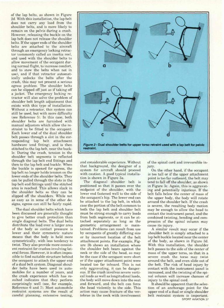
and considerable experience. Withoutthat background, the designer of asystem for aircraft should proceedwith caution. A good typical installa-tion is shown in Figure 3a.
The diagonal shoulder belt ispositioned so that it passes over themidpoint of the shoulder, with thelower end fastened well to the side ofthe occupant's hip. The lower end canbe attached to the lap belt, in whichcase the portion of the belt common toboth the lap belt and shoulder beltmust be strong enough to carry loadsfrom both segments, or it can be at-tached separately as long as thegeometric arrangement is main-tained. Problems can result from useby occupants of greatly differing sizeor by incorrect location of the beltattachment points. For example, Fig-ure 3b shows an installation wherethe shoulder belt bears against theneck or the side of the head, as maybe the case if the occupant were shortor if the upper attachment point werelocated too far inboard. This is notonly aggravating, it can be danger-ous. If the crash involves severe verti-cal loads as well as longitudinal loads,the body will move down into the seatand forward, and the belt can forcethe head violently to the side. Thisaction may cause fracture of the ver-tebrae in the neck with involvement
of the spinal cord and irreversible in-jury.
On the other hand, if the occupantis too tall or if the upper attachmentpoint is too far outboard, the belt maytend to fall off the shoulder, as shownin Figure 3c. Again, this is aggravat-ing and potentially injurious. If thebelt falls below the center of mass ofthe upper body, the body will rotatearound the shoulder belt. If the crashis severe, the resulting body motionmay be enough to allow the head tocontact the instrument panel, and thecombined twisting, bending and com-pression of the spinal column maycause its injury.
A similar result may occur if theshoulder belt is simply attached to alap belt buckle located near the centerof the body, as shown in Figure 3d.With this installation, the shoulderbelt passes to the side of the center ofmass of the upper torso, so that in asevere crash the torso may twistaround the belt, and even slide out ofthe belt. The risk of head injury bycontact with the instrument panel isincreased, and the twisting of the spi-nal column will increase chances ofinjury to the spinal cord.
It should be apparent that the selec-tion of an anchorage point for theupper end of a dual or single shoulderbelt restraint system is important.
SPORT AVIATION 37
Figure 3 • Single diagonal shoulder belt for upper torso restraint used with a lapbelt for pelvic restraint.
This has been discussed in many pub-lications, including an Advisory Cir-cular issued by the FAA (Reference8)*. One concern, in addition to thosealready presented, is to avoid com-pression of the spinal column by theshoulder belt. This may be encoun-tered when the upper end of the shoul-der belt is mounted low, as in Figure4. In this case, the shoulder belt wouldpull down and back on the torso as itresists the forward motion of the oc-cupant. The downward component offorce will place the spinal column incompression, and will add to thestress on the column caused by thevertical component of the crash force.This can be avoided if the angle of theshoulder belt does not fall below 5° ofa longitudinal tangent with the pointof contact on the occupant's shoulder.(Editor's Note: The proper shoulderharness angle was the subject of twoarticles by EAA Board of Directorsmember Dr. Dean Hall. See the Janu-ary 1978 issue of SPORT AVIATION,
38 JANUARY 1985
page 50, and the October 1980 issue,page 18.)
*This Circular also gives advice onother aspects of restraint installation,some of which may be subject to mis-interpretation. In particular, don'tcount on seats being strong enough tocarry restraint loads unless they werespecifically designed to carry theloads, don't depend on local reinforce-ment at restraint attachment pointsto carry the restraint load into pri-mary aircraft structure, and don't ex-pect a 500 Ib. test load on the shoulderbelt attachment point to represent thetrue loads in the restraint during acrash. • • : • • ; • . •••••<;
Restraint LoadsThe forces which exist in a restraint
system during a crash are dependentnot only on the design of the system,but also the size of the occupant andthe conditions of the crash. Obviously,no simple statement of design loads
can be made. However, as a startingpoint, "typical" loads measured in acontrolled laboratory test consideredrepresentative of the crash environ-ment are useful. Such loads weremeasured in a recent test series at theFAA Civil Aeromedical Institutewhich used a 170 pound occupant (ananthropomorphic test dummy), avariety of seat and restraint systemstypical of those found in general avia-tion aircraft, and two test conditions:
a. An impact of 19 G's with a veloc-ity change of 31 fps, with the impactvector acting at an angle of 60° belowthe aircraft longitudinal axis, and,
b. An impact of 26 G's with a veloc-ity change of 42 fps, with the impactvector acting at an angle of 10° to theside of the aircraft longitudinal axis.
While other conditions were alsopresent in the tests, these are of mostinterest. They were considered repre-sentative of crash conditions of gen-eral aviation aircraft at the time ofthe study, and were considered to besurvivable without irreversible in-jury.
The first of these test conditions isprimarily a test of the seat, and thesecond is a test of restraint perfor-mance. Under those conditions, theload in the single diagonal shoulderbelt ranged from 1700 to almost 2300Ibs., depending on design. Loads ineach segment of a dual shoulder beltsystem attached to the seat weremuch lower, less than 700 Ibs. each.Tension loads in each of the lap beltsegments ranged from 1300 to 2600Ibs.
Obviously, these loads are muchgreater than would result from the9G static load criterion often used asa minimum design load for a "minorcrash landing". The dynamic condi-tions of a survivable crash will resultin loads greater than those for the"minor crash landing", and althoughinjuries may occur under these higherimpacts, the injuries should not beirreversible.
Energy Absorption andDelethalization
From the previous discussion, itshould be apparent that some amountof occupant movement will take placein a crash, no matter how good therestraint system is. This is because ofthe natural softness of the humanbody, flailing and the elastic natureof the materials useful for buildingseats and restraint systems. The mag-nitude of this motion is often surpris-ing. In the dynamic tests mentionedabove, head motion approaching 20inches was not uncommon, even insystems with good upper torso re-straint. In these cases, the restraintsystem not only reduces the flailingdistance (called the strike envelope),

but also reduces the velocity of thebody segment, usually the head, atthe point of contact with the aircraftinterior below that which would beexpected if only a lap belt were in use.This makes "delethalization" of thecockpit a feasible practice. Delethali-zation simply means that any struc-ture of component within the strikeenvelope will crush or break at a loadbelow that which causes serious in-jury to the body, and in a manner thatwill not create an injury source. Pad-ding alone is usually insufficient toprovide delethalization at high im-pacts, but is useful for distributingthe load over the body segment. If theload vs. crush distance characteristicsare carefully controlled, the structuremay be "energy absorbing", in thesense that the energy (velocity) of thesecondary impact is dissipated bycrushing the material. The concept ofenergy absorption is an importanttool in the design of advanced crashprotection systems, but is beyond thelimits of this article (see Reference 9for a more complete discussion). Youshould be aware that the control ofload and crush distance (deformation)is important in managing crashenergy. Some materials or designs,such as those which use materialswith low ductility, inherently havepoor energy absorbing characteristicsand should be avoided in crash protec-tion sysems unless special design pro-visions are made.
SummaryThe design of an effective restraint
system for aircraft is not a simpletask. Computer programs have beendeveloped to guide the designer inthis area, and dynamic testing is afunctional tool in a final demonstra-tion of system performance. If thesetools are not available, certain basicguidelines will aid in achieving a gooddesign:
a. Install the lap belt portion of therestraint so that it acts on the pelvisof the occupant at an angle of about45° with the longitudinal axis of theaircraft.
b. Provide upper torso restraint.c. If dual shoulder belts are used,
make sure that the shoulder beltswon't pull the lap belt off the pelvisduring the crash.
d. If a single diagonal shoulder beltis used, anchor the lower end well tothe side of the hip of the occupant,and anchor the upper end so that thebelt passes midway over the shoulderof the occupant using the system.
e. Shoulder belts shouldn't pulldown on the shoulders more thanabout 5°.
f. Keep belt lengths as short as pos-sible to minimize belt stretch and oc-cupant displacement.
g. Recognize that the restraintloads in a severe but survivable crashcan exceed those calculated by con-ventional static analysis techniquesfor the minor crash landing, and pro-vide an adequate load path throughthe restraint and into primary struc-ture.
h. Provide a means of easily releas-ing the restraint system, so that rapidegress from the aircraft is possible ifnecessary.
i. Consider the seat and cockpit in-terior as essential parts of the crashinjury protection system.
The main body of this article hasgiven some insight into the means offollowing these guidelines. Two otherconsiderations of a more general na-ture should be kept in mind whenconsidering aircraft restraint sys-tems. Remember that an effectivecrash injury protection system in-cludes considerations in the design ofthe airframe, the seat, the aircraftinterior and the restraint, and mostimportant, consideration of the occu-pant. The best system will not provideprotection if the occupant chooses notto use it or if it is used improperly.Comfort, convenience and "pleasureof use" may be as important as theengineering of the system. Finally,keep the system as simple as possible,and pay attention to design details.The prevalent cause of difficulty withseat and restraint system designs, inthe experience of the author, has beeninadequate consideration of some ap-parently minor design detail.
Figure 4 - A low anchor point for theupper end of a shoulder belt system canresult in a spinal column compressionin a crash.
THE SHOULDER HARNESS PLEDGESince the beginnings of EAA in
January of 1953, the organization hasencouraged its members to install anduse shoulder harnesses in their per-sonal aircraft. A Shoulder HarnessPledge has always been an integralpart of the EAA membership applica-tion and has been signed by EAAersfor the past 32 years. More impor-tantly, a check of homebuilts on theline at Oshkosh will find one withoutshoulder harness a rare exception.EAAers can be justly proud that theirefforts have been significant in bring-ing about both wider use of the safetydevice and in changing attitudes infavor of their acceptance.
References1. Swearingen, J. J.: General Avia-
tion Structures Directly Responsiblefor Trauma in Crash Decelerations,FAA-AM-71-3. Federal Aviation Ad-ministration, Washington, DC 20590.
2. Kirkham, W. R., Wicks, S. M.,Lowery, D. L.: CrashworthinessStudies: Cabin, Seat, Restraint andInjury Findings in Selected GeneralAviation Accidents, FAA-AM-82-7.Federal Aviation Administration,Washington, DC 20590.
3. Laananen, D. L., Bolukbasi, A.0., Coltman, J. W.: Computer Simula-tion of an Aircraft Seat and Occupantin a Crash Environment, DGT/FAA/CT-82-33. Federal Aviation Adminis-tration, Washington, DC 20590.
4. King, A. I., Chou, C.: Mathemat-ical Modeling, Simulation and Ex-perimental Testing of BiomechanicalSystem Crash Response, AIAA Paper75-272. American Institute ofAeronautics and Astronautics, NewYork, NY 10019.
5. Parks, D. L., Twigg, D. W.: At-tendant Restraint System TechnicalEvaluation and Guidelines, BoeingDocument D6-44779TN-O. BoeingCommercial Airplane Company,Seattle, WA 98124.
6. Patrick, L., Aandersson, A.:Three-Point Harness Accident andLaboratory Data Comparison, SAE741181. Society of Automotive En-gineers, Inc., Warrendale, PA 15096.
7. Advances in Belt Restraint Sys-tems: Design, Performance andUsage, SAE P-141. Society of Auto-motive Engineers, Inc., Warrendale,PA 15096.
8. Acceptable Methods, Techniquesand Practices, Aircraft Alterations,AC 43.13-2A. Federal Aviation Ad-ministration, Washington, DC 20590.
9. Aircraft Crash Survival DesignGuide, USARTL-TR-79-22. Preparedby SIMULA, Inc. for the U. S. ArmyResearch and TechnologyLaboratories (AVRADCOM), FortEustis, VA 32604.
SPORT AVIATION 39


![Crase v. Shasta Beverages, Inc. · [Cite as Crase v.Shasta Beverages, Inc., 2012-Ohio-326.] IN THE COURT OF APPEALS OF OHIO TENTH APPELLATE DISTRICT Alden E. Crase, : …](https://img.pdfslide.us/doc/110x75/5acd15007f8b9a875a8d5a73/crase-v-shasta-beverages-inc-cite-as-crase-vshasta-beverages-inc-2012-ohio-326.jpg)