Embed Size (px)
Citation preview
R
AG
a
ARRA
1
wbhsfftihSeu1eCdcSPItsu
0d
Nuclear Engineering and Design 242 (2012) 52– 62
Contents lists available at SciVerse ScienceDirect
Nuclear Engineering and Design
jo u r n al hom epage : www.elsev ier .com/ locate /nucengdes
esponse of steel-concrete composite panels to in-plane loading
ri Danay ∗
enor Engineering Inc., 14015 Marine Dr., Whiterock, BC, Canada V4B 1A6
r t i c l e i n f o
rticle history:eceived 22 July 2011eceived in revised form 3 October 2011ccepted 4 October 2011
a b s t r a c t
Steel-Concrete Composite (SCC) panels consist of steel faceplates with welded shear studs and concreteinfill. The shear studs, which perform a similar function to bond of rebars in reinforced concrete, act assprings resisting the shear slip between the faceplates and concrete. In spite of extensive research in the1980s and 1990s due to the interest in using SCC in offshore construction and in nuclear power plants,and recently related Codes, there is no analytical method to-date to predict the shear studs response to
in-plane loading. Shear connectors are sized according to various criteria unrelated to their actual forcesunder in-plane loads, such as prevention of faceplate buckling or out-of-plane shear resistance. This paperpresents a closed analytical solution of the equilibrium and compatibility differential equations for steeland concrete displacements of SCC panels, based on distributed shear springs idealization. Analyticalresults presented in this paper are validated by test results of SCC panels loaded by pure shear forces andcan be used as practical design formulas for the in-plane portion of the design loads.. Introduction
Steel-Concrete Composite (SCC) panels are built as steel boxesith concrete infill. To act together as a composite structure, as
ond between steel plates and concrete is neglected, the steel platesave an array of welded shear studs on the inside faces. The sheartuds, which perform a similar function to bond of rebars in rein-orced concrete, act as springs resisting the shear slip between theaceplates and concrete. Due to the interest in offshore construc-ion during the 1980s, a number of extensive research programsnto the behavior and failure mechanisms of composite structuresave been carried out in Canada, Japan, Great Britain and Unitedtates (Fukumoto et al., 1987; Matsuishi and Iwata, 1987; Ohnot al., 1987; Akiyama et al., 1989, 1991). Renewed interest in SCCse in nuclear power plants resulted in extensive research in the990s, the bulk of it performed in Japan (Usami et al., 1995; Suzukit al., 1995; Ozaki et al., 2004), and in the publication of an SCCode of Practice (JEAG 4608, 2005), issued by the Nuclear Stan-ards Committee of Japan Electrical Association. A similar Code isurrently under preparation in US (Appendix N9 of AISC, 2010).ignificant experiment research has been recently performed aturdue University as part of Westinghouse AP1000 test program.n spite of this, there is no analytical method to-date to predict
he shear studs response to in-plane loading. Shear connectors areized according to various criteria unrelated to their actual forcesnder in-plane loads, such as prevention of faceplate buckling or∗ Corresponding author. Tel.: +1 604 5609030.E-mail address: [email protected]
029-5493/$ – see front matter © 2011 Elsevier B.V. All rights reserved.oi:10.1016/j.nucengdes.2011.10.006
© 2011 Elsevier B.V. All rights reserved.
out-of-plane shear resistance. An alternative method is to use Par.Q1.11.4 of AISC N690-94 (AISC, 1994), which applies to compositeaction of steel beams with concrete slabs under out-of-plane load-ing, requiring the shear studs to develop one half of the yield stressin the faceplate between the point of maximum positive momentand point of zero moment. Several studies, using “push-out” testsof shear studs, were performed to assess their shear-slip character-istics in composite structures (Viest, 1956; Ollgaard et al., 1971).They determined that the load slip curves are non-linear due to acombination of crushing of the concrete in the concrete wedge infront of the stud and flexural/shear yield of the stud. Nonetheless,for practical applications, the curves may be reasonably idealizedby a linear spring coefficient K, the latter proportional to the con-crete strength and the shear stud area. This paper presents a closedanalytical solution of the equilibrium and compatibility differen-tial equations for steel and concrete displacements of SCC panels,based on the shear studs being modeled as uniformly distributedshear springs over the steel plate area.
2. Analytical methodology
2.1. Smeared connectivity of the welded shear studs
Shear studs spacing is relatively small in comparison to theSCC panels plan dimensions, typically a few percent of the lat-
ter. As a result of this it is reasonable to treat the steel to concreteconnectivity as evenly distributed (or “smeared”), in a similar man-ner to reinforced concrete connectivity to rebars. The elastic shearload-slip function of the distributed interface forces f may then be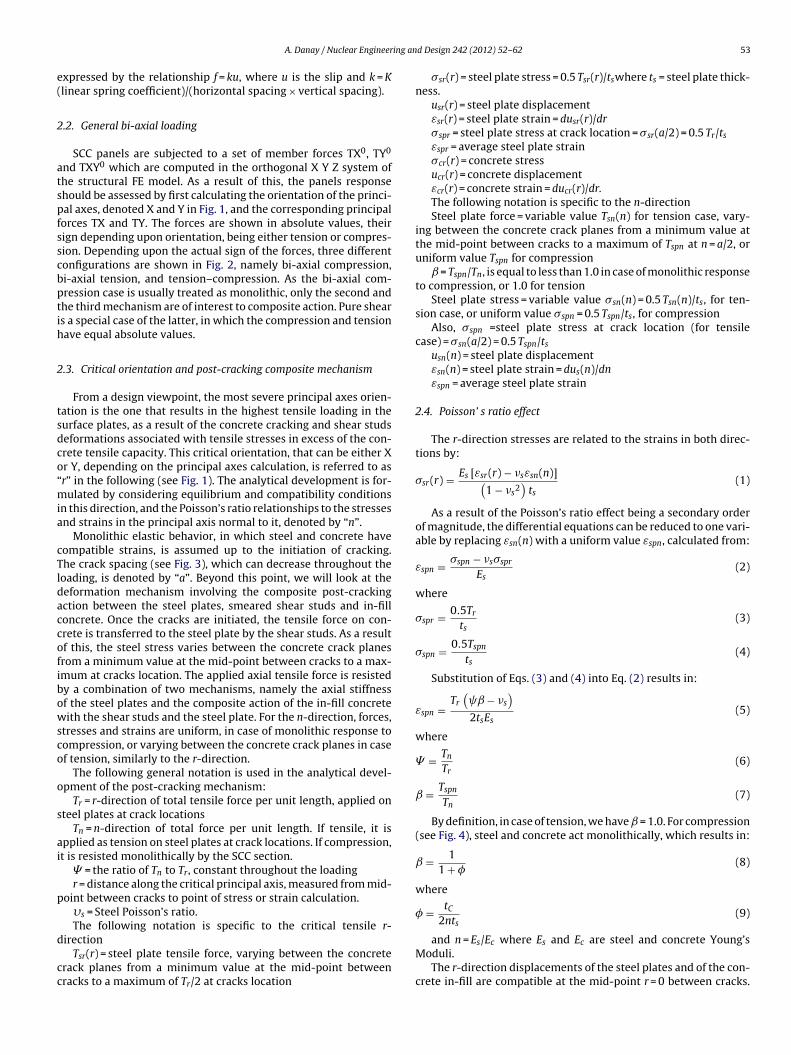
ing an
e(
2
atspfsscbptih
2
tsdco“mia
cTldaccofibowsco
o
s
ai
p
d
cc
A. Danay / Nuclear Engineer
xpressed by the relationship f = ku, where u is the slip and k = Klinear spring coefficient)/(horizontal spacing × vertical spacing).
.2. General bi-axial loading
SCC panels are subjected to a set of member forces TX0, TY0
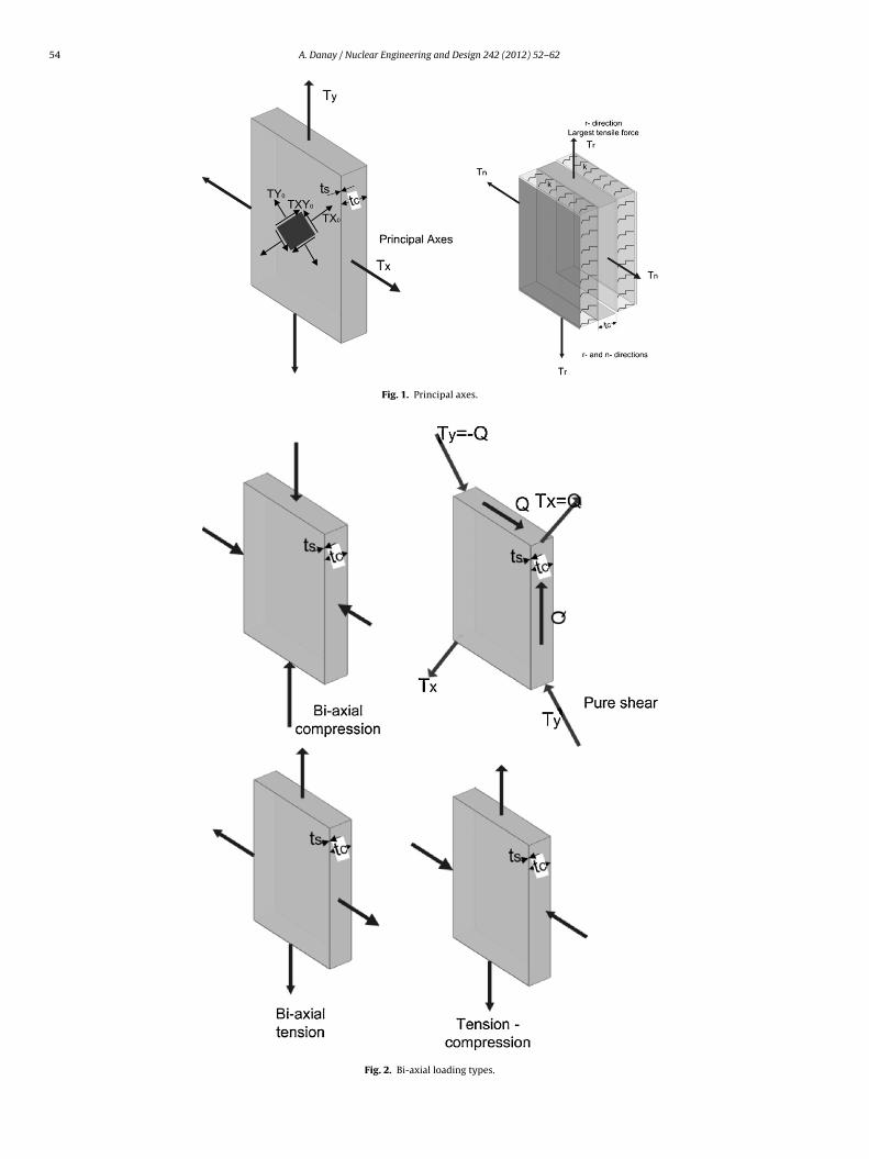
nd TXY0 which are computed in the orthogonal X Y Z system ofhe structural FE model. As a result of this, the panels responsehould be assessed by first calculating the orientation of the princi-al axes, denoted X and Y in Fig. 1, and the corresponding principalorces TX and TY. The forces are shown in absolute values, theirign depending upon orientation, being either tension or compres-ion. Depending upon the actual sign of the forces, three differentonfigurations are shown in Fig. 2, namely bi-axial compression,i-axial tension, and tension–compression. As the bi-axial com-ression case is usually treated as monolithic, only the second andhe third mechanism are of interest to composite action. Pure shears a special case of the latter, in which the compression and tensionave equal absolute values.
.3. Critical orientation and post-cracking composite mechanism
From a design viewpoint, the most severe principal axes orien-ation is the one that results in the highest tensile loading in theurface plates, as a result of the concrete cracking and shear studseformations associated with tensile stresses in excess of the con-rete tensile capacity. This critical orientation, that can be either Xr Y, depending on the principal axes calculation, is referred to asr” in the following (see Fig. 1). The analytical development is for-ulated by considering equilibrium and compatibility conditions
n this direction, and the Poisson’s ratio relationships to the stressesnd strains in the principal axis normal to it, denoted by “n”.
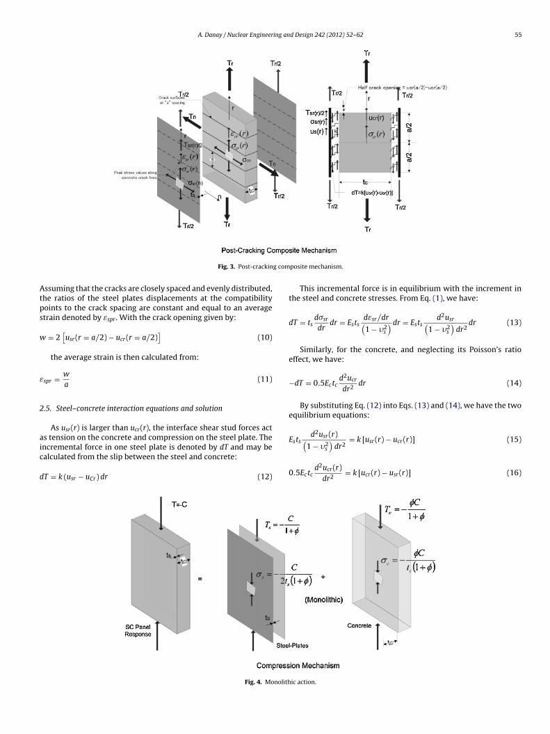
Monolithic elastic behavior, in which steel and concrete haveompatible strains, is assumed up to the initiation of cracking.he crack spacing (see Fig. 3), which can decrease throughout theoading, is denoted by “a”. Beyond this point, we will look at theeformation mechanism involving the composite post-crackingction between the steel plates, smeared shear studs and in-filloncrete. Once the cracks are initiated, the tensile force on con-rete is transferred to the steel plate by the shear studs. As a resultf this, the steel stress varies between the concrete crack planesrom a minimum value at the mid-point between cracks to a max-mum at cracks location. The applied axial tensile force is resistedy a combination of two mechanisms, namely the axial stiffnessf the steel plates and the composite action of the in-fill concreteith the shear studs and the steel plate. For the n-direction, forces,
tresses and strains are uniform, in case of monolithic response toompression, or varying between the concrete crack planes in casef tension, similarly to the r-direction.
The following general notation is used in the analytical devel-pment of the post-cracking mechanism:
Tr = r-direction of total tensile force per unit length, applied onteel plates at crack locations
Tn = n-direction of total force per unit length. If tensile, it ispplied as tension on steel plates at crack locations. If compression,t is resisted monolithically by the SCC section.� = the ratio of Tn to Tr, constant throughout the loadingr = distance along the critical principal axis, measured from mid-
oint between cracks to point of stress or strain calculation.�s = Steel Poisson’s ratio.The following notation is specific to the critical tensile r-
irectionTsr(r) = steel plate tensile force, varying between the concrete
rack planes from a minimum value at the mid-point betweenracks to a maximum of Tr/2 at cracks location
d Design 242 (2012) 52– 62 53
�sr(r) = steel plate stress = 0.5 Tsr(r)/tswhere ts = steel plate thick-ness.
usr(r) = steel plate displacementεsr(r) = steel plate strain = dusr(r)/dr�spr = steel plate stress at crack location = �sr(a/2) = 0.5 Tr/ts
εspr = average steel plate strain�cr(r) = concrete stressucr(r) = concrete displacementεcr(r) = concrete strain = ducr(r)/dr.The following notation is specific to the n-directionSteel plate force = variable value Tsn(n) for tension case, vary-
ing between the concrete crack planes from a minimum value atthe mid-point between cracks to a maximum of Tspn at n = a/2, oruniform value Tspn for compression
= Tspn/Tn, is equal to less than 1.0 in case of monolithic responseto compression, or 1.0 for tension
Steel plate stress = variable value �sn(n) = 0.5 Tsn(n)/ts, for ten-sion case, or uniform value �spn = 0.5 Tspn/ts, for compression
Also, �spn =steel plate stress at crack location (for tensilecase) = �sn(a/2) = 0.5 Tspn/ts
usn(n) = steel plate displacementεsn(n) = steel plate strain = dus(n)/dnεspn = average steel plate strain
2.4. Poisson’ s ratio effect
The r-direction stresses are related to the strains in both direc-tions by:
�sr(r) = Es [εsr(r) − �sεsn(n)](1 − �s2
)ts
(1)
As a result of the Poisson’s ratio effect being a secondary orderof magnitude, the differential equations can be reduced to one vari-able by replacing εsn(n) with a uniform value εspn, calculated from:
εspn = �spn − �s�sprEs
(2)
where
�spr = 0.5Trts
(3)
�spn = 0.5Tspnts
(4)
Substitution of Eqs. (3) and (4) into Eq. (2) results in:
εspn =Tr
( − �s
)2tsEs
(5)
where
� = TnTr
(6)
= TspnTn
(7)
By definition, in case of tension, we have = 1.0. For compression(see Fig. 4), steel and concrete act monolithically, which results in:
ˇ = 11 + �
(8)
where
� = tC2nts
(9)
and n = Es/Ec where Es and Ec are steel and concrete Young’sModuli.
The r-direction displacements of the steel plates and of the con-crete in-fill are compatible at the mid-point r = 0 between cracks.
54 A. Danay / Nuclear Engineering and Design 242 (2012) 52– 62
Fig. 1. Principal axes.
Fig. 2. Bi-axial loading types.
A. Danay / Nuclear Engineering and Design 242 (2012) 52– 62 55
g com
Atps
w
ε
2
aic
d
Fig. 3. Post-crackin
ssuming that the cracks are closely spaced and evenly distributed,he ratios of the steel plates displacements at the compatibilityoints to the crack spacing are constant and equal to an averagetrain denoted by εspr. With the crack opening given by:
= 2[usr(r = a/2) − ucr(r = a/2)
](10)
the average strain is then calculated from:
spr = w
a(11)
.5. Steel–concrete interaction equations and solution
As usr(r) is larger than ucr(r), the interface shear stud forces acts tension on the concrete and compression on the steel plate. The
ncremental force in one steel plate is denoted by dT and may bealculated from the slip between the steel and concrete:T = k (usr − uCr)dr (12)
Fig. 4. Monolith
posite mechanism.
This incremental force is in equilibrium with the increment inthe steel and concrete stresses. From Eq. (1), we have:
dT = tsd�srdrdr = Ests
dεsr/dr(1 − �2
s
)dr = Estsd2usr(
1 − �2s
)dr2
dr (13)
Similarly, for the concrete, and neglecting its Poisson’s ratioeffect, we have:
−dT = 0.5Ectcd2ucrdr2
dr (14)
By substituting Eq. (12) into Eqs. (13) and (14), we have the twoequilibrium equations:
Estsd2usr(r)( ) = k [usr(r) − ucr(r)] (15)
1 − �2s dr2
0.5Ectcd2ucr(r)dr2
= k [ucr(r) − usr(r)] (16)
ic action.
5 ing an
u
u
h
e
e
fi⎧⎨⎩⎧⎨⎩
d
�
u
u
�
�
d
C
C
C
C
t
�
6 A. Danay / Nuclear Engineer
The proposed solutions are:
cr(r) = C1e�r + C2e
−�r + 2C5r
a(17)
sr(r) = C3e�r + C4e
−�r + 2C5r
a(18)
By substitution of Eqs. (17) and (18) into Eqs. (15) and (16) weave:
�r[0.5Ectc�2C1 − kC1 + kC3
]+ e−�r
[0.5Ectc�2C2 − kC2 + kC4
]= 0
(19)
�r
[Ests
1 − �2s
�2C3+kC1 − kC3
]+ e−�r
[Ests
1 − �2s
�2C4 + kC2 − kC4
]=0
(20)
In order to have a non-trivial solution we must have zero coef-cients for e�r and e−�r in Eqs. (19) and (20), which yields:
C1(
0.5Ectc�2 − k)
+ C3k = 0
C1k + C3
(Ests
1 − �2s
�2 − k
)= 0
⎫⎬⎭ (21)
C2(
0.5Ectc�2 − k)
+ C4k = 0
C2k + C4
(EStS
1 − �2S
�2 − k
)= 0
⎫⎬⎭ (22)
Eqs. (21) and (22) require that:
et
⎧⎨⎩
(0.5ECtC�2 − k
)....k
k.........
(EStS
1 − �2S
�2 − k
)⎫⎬⎭ = 0 (23)
which results in:
=
√√√√k(
1 − �2S + 1
�
)EStS
(24)
The boundary conditions may be expressed by:
sr(0) = 0 (25)
cr(0) = 0 (26)
sr (±a/2) = Es[εsr (r = ±a/2) − �sεspn
]= Es
[dusr (±a/2)
dr− �sεspn
]= Tr
2ts(27)
cr(±a/2) = ES[εcr(±a/2)
]= ES
ducr(±a/2)dr
= 0 (28)
Substituting Eq. (5) into Eq. (27) results in:
dusr(±a/2)dr
= Tr2tsEs
(1 + ˇ�s − �2
s
)(29)
The substitution of the expressions for the steel and concreteisplacements into the four boundary conditions yields:
3 + C4 = 0 (30)
1 + C2 = 0 (31)
3�e�a/2 − C4�e
−�a/2 + 2C5
a=Tr
(1 + ˇ�s − �2
s
)2tsES
(32)
1�e�a/2 − C2�e
−�a/2 + 2C5
a= 0 (33)
The additional equation required to solve the five constants C1o C5 is given in Eq. (12), which yields after substitution of Eq. (14):
C1 + C3 = 0 (34)
d Design 242 (2012) 52– 62
The solution of Eqs. (30)–(34) is:
C1 = −Tr
(1 + ˇ�s − �2
s
)2ts� (1 + �)
(e�a/2 + e−�a/2
)ES
(35)
C2 = −C1 (36)
C3 =�Tr
(1 + ˇ�s − �2
s
)2ts� (1 + �)
(e�a/2 + e−�a/2
)ES
(37)
C4 = −C3 (38)
C5 =aTr
(1 + ˇ�s − �2
S
)4tsEs (1 + �)
(39)
Hence, from Eqs. (7) and (8):
ucr =Tr
(1 + ˇ�s − �2
s
)2ts (1 + �)ES
[− e�r − e−�r
�(e�a/2 + e−�a/2
) + r
](40)
usr =Tr
(1 + ˇ�s − �2
s
)2ts (1 + �)ES
[�
(e�r − e−�r
)�(e�a/2 + e−�a/a
) + r
](41)
2.6. Crack spacing
Concrete stresses vary between zero at r = a/2 to a maximumat r = 0. A crack will develop at r = 0 if the concrete stress �cr(0) =Ecducrdr (0) = ft , where ft = tensile strength of concrete. Substituting
this condition in Eq. (40) results in:
ft =Tr
(1 + ˇ�s − �2
s
)2ts (1 + �)n
[− 1
cosh(�a/2
) + 1
](42)
The crack spacing solution “a” is then:
a = 2 arccos h
�
⎡⎣ 1
1 − 2tsnft (1+�)Tr(1+ ˇ�s−�2
s )
⎤⎦ (43)
2.7. Secant stiffness
The average strain in the composite mechanism is taken as:
εspr = usr(a/2)a2
=Tr
(1 + ˇ�s − �2
s
)ats (1 + �)ES
[�
(e�a/2 − e−�a/2
)�(e�a/2 + e−�a/2
) + a
2
]
=Tr
(1 + ˇ�s − �2
s
)2ts (1 + �)ES
[2� tanh(�a/2)
a�+ 1
](44)
from which:
Tr = 2ts (1 + �)ES(1 + ˇ�s − �2
s
)[2� tanh(�a/2)
a� + 1]εspr (45)
Eq. (45) may be written as:
Tr = Krεspr (46)
where Kr is the secant stiffness of the cracked panel, given by:
Kr =[
1 + �2� tanh(�a/2)
a� + 1
]2tsES
1 + ˇ�s − �2s
(47)
The ratio ϕ of the cracked to un-cracked shear stiffness can then
be calculated from:ϕ =
[1+�
2� tanh(�a/2)a�
+1
]2tsES
1+ ˇ�s−�2s
Ectc + 2tsEs= 1(
2� tanh(�a/2)a�
+ 1)(
1 + ˇ�s − �2s
) (48)
A. Danay / Nuclear Engineering and Design 242 (2012) 52– 62 57
e shea
2
cTmi
ε
fi
�
m
� + 1
2
letr
w
F
= εspr +2tsEs
(55)
Table 1Special loading cases.
Notes
Fig. 5. Pur
.8. Steel and concrete stresses
Steel and concrete stresses are calculated based on the lowestrack spacing value corresponding to the highest applied value ofr. Denoting those by amin and Trm, respectively, the correspondinginimum crack spacing and maximum force, the peak strain εmax
s calculated from Eq. (45):
max =Trm
(1 + ˇ�s − �2
s
)[2� tan h(�amin/2)
amin�+ 1
]2ts (1 + �)ES
(49)
Peak steel stress values occur at the locations of the crack sur-aces, at r = amin/2, where the peak composite mechanism force Trm
s transferred to the steel plates:
s max = Trm2ts
(50)
The concrete tensile stress varies from zero at r = amin/2 to aaximum at r = 0. From Eq. (40) we have:
cr max = ducr(r)dr
(r = 0) =(
1 + ˇ�s − �2s
)Tcrm
2ts (1 + �)
[− 1
cos h(�amin/2
).9. Peak crack opening and shear studs forces
Similarly to peak and concrete stresses, these values occur at theoad level corresponding to the smallest crack spacing and high-st applied axial force. The peak crack opening is equal to twicehe difference between the steel and concrete displacements at
= amin/2.Consequently, from Eqs. (40) and (41) we have:
cr =tan h(�amin/2)
(1 + ˇ�s − �2
s
)Trm
(52)
�tsEsThe largest shear stud force is at r = amin/2 as well:
st max = k[usr(amin/2) − ucr(amin/2
]= kwcr/2 (53)
r loading.
](51)
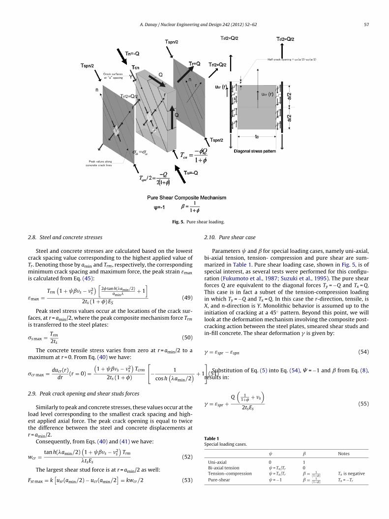
2.10. Pure shear case
Parameters and for special loading cases, namely uni-axial,bi-axial tension, tension- compression and pure shear are sum-marized in Table 1. Pure shear loading case, shown in Fig. 5, is ofspecial interest, as several tests were performed for this configu-ration (Fukumoto et al., 1987; Suzuki et al., 1995). The pure shearforces Q are equivalent to the diagonal forces Ty = −Q and Tx = Q.This case is in fact a subset of the tension-compression loadingin which Ty = −Q and Tx = Q. In this case the r-direction, tensile, isX, and n-direction is Y. Monolithic behavior is assumed up to theinitiation of cracking at a 45◦ pattern. Beyond this point, we willlook at the deformation mechanism involving the composite post-cracking action between the steel plates, smeared shear studs andin-fill concrete. The shear deformation is given by:
= εspr − εspn (54)
Substitution of Eq. (5) into Eq. (54), � = −1 and from Eq. (8),results in:
Q(
11+� + �s
)
Uni-axial 0 1Bi-axial tension = Tn/Tr 0Tension–compression = Tn/Tr = 1
(1+�) Tn is negativePure-shear = −1 = 1
(1+�) Tn = −Tr
58 A. Danay / Nuclear Engineering an
3
3
lsapts
3
(lbKisK
3
beespti
Fig. 6. Example panel.
. Numerical examples
.1. General
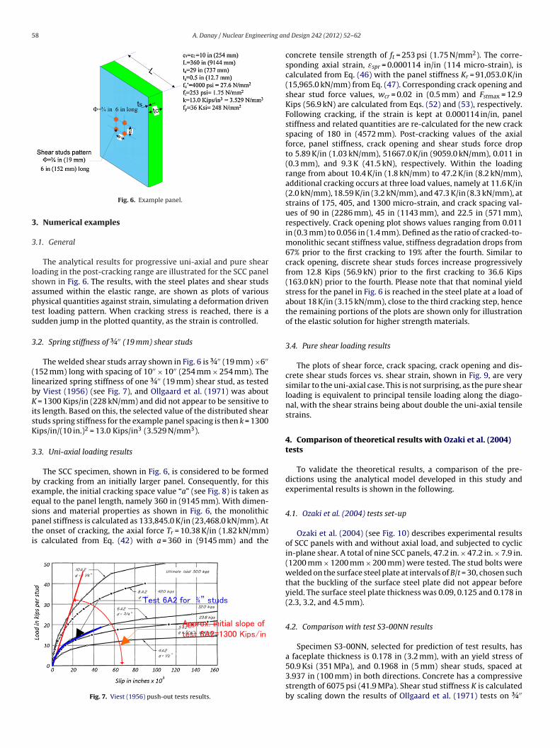
The analytical results for progressive uni-axial and pure shearoading in the post-cracking range are illustrated for the SCC panelhown in Fig. 6. The results, with the steel plates and shear studsssumed within the elastic range, are shown as plots of varioushysical quantities against strain, simulating a deformation drivenest loading pattern. When cracking stress is reached, there is audden jump in the plotted quantity, as the strain is controlled.
.2. Spring stiffness of ¾′′ (19 mm) shear studs
The welded shear studs array shown in Fig. 6 is ¾′′ (19 mm) ×6′′
152 mm) long with spacing of 10′′ × 10′′ (254 mm × 254 mm). Theinearized spring stiffness of one ¾′′ (19 mm) shear stud, as testedy Viest (1956) (see Fig. 7), and Ollgaard et al. (1971) was about
= 1300 Kips/in (228 kN/mm) and did not appear to be sensitive tots length. Based on this, the selected value of the distributed sheartuds spring stiffness for the example panel spacing is then k = 1300ips/in/(10 in.)2 = 13.0 Kips/in3 (3.529 N/mm3).
.3. Uni-axial loading results
The SCC specimen, shown in Fig. 6, is considered to be formedy cracking from an initially larger panel. Consequently, for thisxample, the initial cracking space value “a” (see Fig. 8) is taken asqual to the panel length, namely 360 in (9145 mm). With dimen-
ions and material properties as shown in Fig. 6, the monolithicanel stiffness is calculated as 133,845.0 K/in (23,468.0 kN/mm). Athe onset of cracking, the axial force Tr = 10.38 K/in (1.82 kN/mm)s calculated from Eq. (42) with a = 360 in (9145 mm) and theFig. 7. Viest (1956) push-out tests results.
d Design 242 (2012) 52– 62
concrete tensile strength of ft = 253 psi (1.75 N/mm2). The corre-sponding axial strain, εspr = 0.000114 in/in (114 micro-strain), iscalculated from Eq. (46) with the panel stiffness Kr = 91,053.0 K/in(15,965.0 kN/mm) from Eq. (47). Corresponding crack opening andshear stud force values, wcr = 0.02 in (0.5 mm) and Fstmax = 12.9Kips (56.9 kN) are calculated from Eqs. (52) and (53), respectively.Following cracking, if the strain is kept at 0.000114 in/in, panelstiffness and related quantities are re-calculated for the new crackspacing of 180 in (4572 mm). Post-cracking values of the axialforce, panel stiffness, crack opening and shear studs force dropto 5.89 K/in (1.03 kN/mm), 51667.0 K/in (9059.0 kN/mm), 0.011 in(0.3 mm), and 9.3 K (41.5 kN), respectively. Within the loadingrange from about 10.4 K/in (1.8 kN/mm) to 47.2 K/in (8.2 kN/mm),additional cracking occurs at three load values, namely at 11.6 K/in(2.0 kN/mm), 18.59 K/in (3.2 kN/mm), and 47.3 K/in (8.3 kN/mm), atstrains of 175, 405, and 1300 micro-strain, and crack spacing val-ues of 90 in (2286 mm), 45 in (1143 mm), and 22.5 in (571 mm),respectively. Crack opening plot shows values ranging from 0.011in (0.3 mm) to 0.056 in (1.4 mm). Defined as the ratio of cracked-to-monolithic secant stiffness value, stiffness degradation drops from67% prior to the first cracking to 19% after the fourth. Similar tocrack opening, discrete shear studs forces increase progressivelyfrom 12.8 Kips (56.9 kN) prior to the first cracking to 36.6 Kips(163.0 kN) prior to the fourth. Please note that that nominal yieldstress for the panel in Fig. 6 is reached in the steel plate at a load ofabout 18 K/in (3.15 kN/mm), close to the third cracking step, hencethe remaining portions of the plots are shown only for illustrationof the elastic solution for higher strength materials.
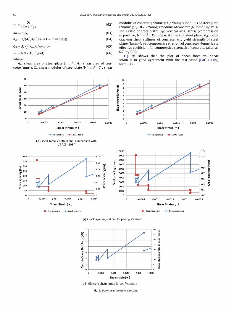
3.4. Pure shear loading results
The plots of shear force, crack spacing, crack opening and dis-crete shear studs forces vs. shear strain, shown in Fig. 9, are verysimilar to the uni-axial case. This is not surprising, as the pure shearloading is equivalent to principal tensile loading along the diago-nal, with the shear strains being about double the uni-axial tensilestrains.
4. Comparison of theoretical results with Ozaki et al. (2004)tests
To validate the theoretical results, a comparison of the pre-dictions using the analytical model developed in this study andexperimental results is shown in the following.
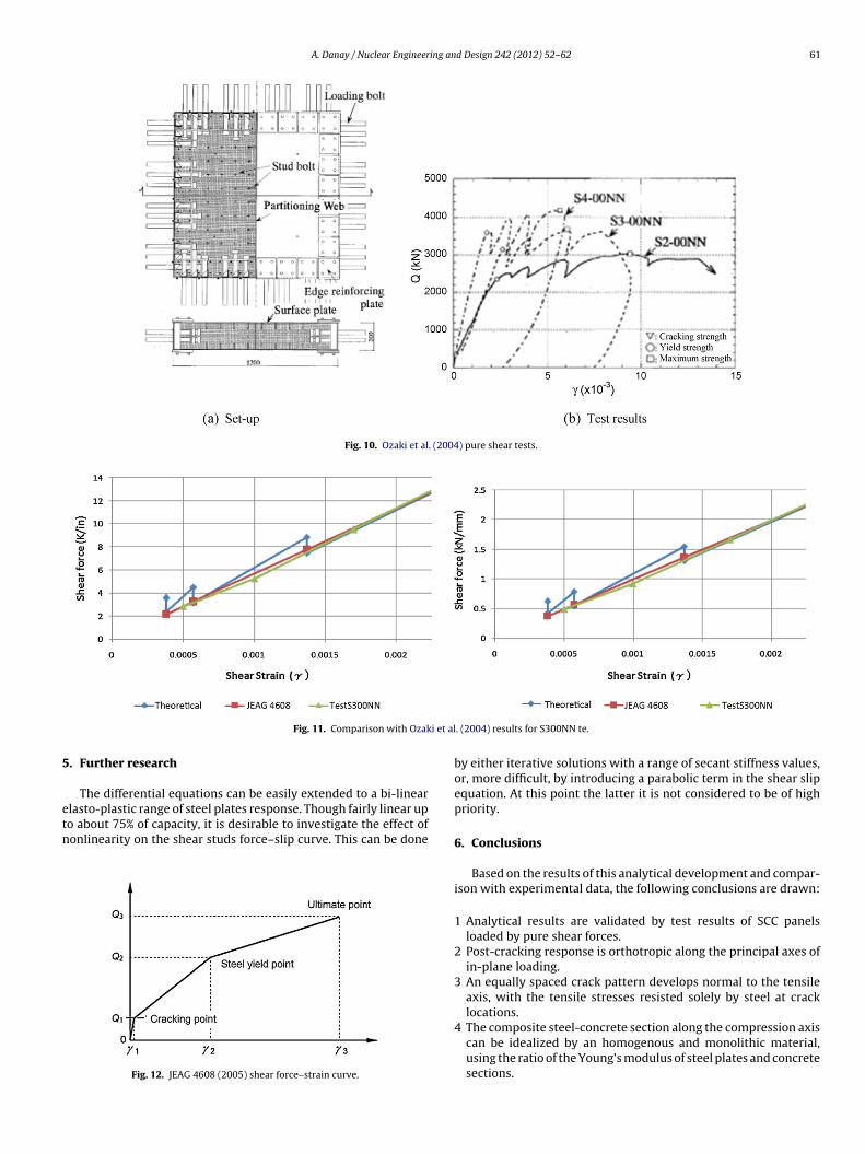
4.1. Ozaki et al. (2004) tests set-up
Ozaki et al. (2004) (see Fig. 10) describes experimental resultsof SCC panels with and without axial load, and subjected to cyclicin-plane shear. A total of nine SCC panels, 47.2 in. × 47.2 in. × 7.9 in.(1200 mm × 1200 mm × 200 mm) were tested. The stud bolts werewelded on the surface steel plate at intervals of B/t = 30, chosen suchthat the buckling of the surface steel plate did not appear beforeyield. The surface steel plate thickness was 0.09, 0.125 and 0.178 in(2.3, 3.2, and 4.5 mm).
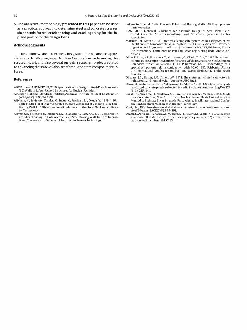
4.2. Comparison with test S3-00NN results
Specimen S3-00NN, selected for prediction of test results, hasa faceplate thickness is 0.178 in (3.2 mm), with an yield stress of
50.9 Ksi (351 MPa), and 0.1968 in (5 mm) shear studs, spaced at3.937 in (100 mm) in both directions. Concrete has a compressivestrength of 6075 psi (41.9 MPa). Shear stud stiffness K is calculatedby scaling down the results of Ollgaard et al. (1971) tests on ¾′′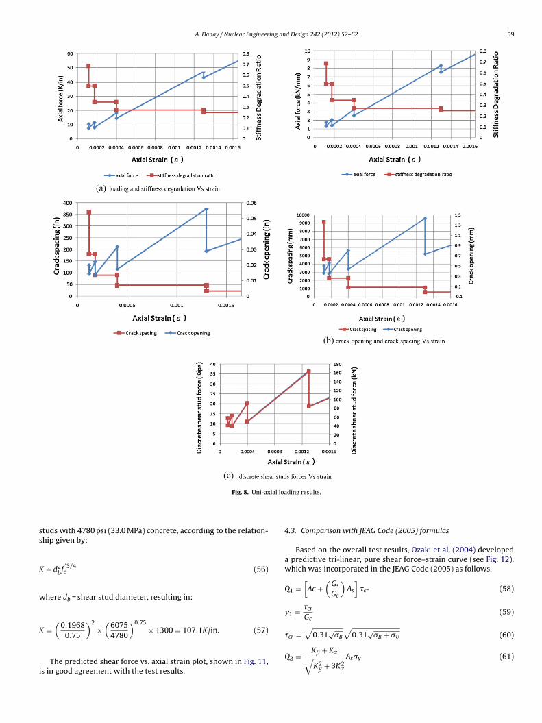
A. Danay / Nuclear Engineering and Design 242 (2012) 52– 62 59
ial loa
ss
K
w
K
i
Fig. 8. Uni-ax
tuds with 4780 psi (33.0 MPa) concrete, according to the relation-hip given by:
÷ d2bf
′3/4c (56)
here db = shear stud diameter, resulting in:
=(
0.19680.75
)2×
(60754780
)0.75× 1300 = 107.1K/in. (57)
The predicted shear force vs. axial strain plot, shown in Fig. 11,s in good agreement with the test results.
ding results.
4.3. Comparison with JEAG Code (2005) formulas
Based on the overall test results, Ozaki et al. (2004) developeda predictive tri-linear, pure shear force–strain curve (see Fig. 12),which was incorporated in the JEAG Code (2005) as follows.
Q1 =[Ac +
(GsGc
)As
]�cr (58)
1 = �crGc
(59)
�cr =√
0.31√�B
√0.31
√�B + �� (60)
Q2 = Kˇ + K˛√K2ˇ
+ 3K2˛
As�y (61)
6 ing an
K
K
Q
w
c
0 A. Danay / Nuclear Engineer
2 = Q2
(K + Kˇ)(62)
˛ = AsGs (63)
ˇ = 1/{4/(AcE′c) + 2(1 − �s)/(AsEs)} (64)
3 = Ac√
(As/Ac)�Y�1�B (65)
−3
3 = 6.0 × 10 (rad) (66)hereAs: shear area of steel plate (mm2); Ac: shear area of con-
rete (mm2); Gs: shear modulus of steel plate (N/mm2); Gc: shear
Fig. 9. Pure shear the
d Design 242 (2012) 52– 62
modulus of concrete (N/mm2); Es: Young’s modulus of steel plate(N/mm2); Ec’: 0.7 × Young’s modulus of concrete (N/mm2); �s: Pois-son’s ratio of steel plate; ��: vertical axial stress (compressionis positive, N/mm2); K˛: shear stiffness of steel plate; Kˇ: post-cracking shear stiffness of concrete; �y: yield strength of steelplate (N/mm2); �B: compressive strength of concrete (N/mm2); �1:effective coefficient for compressive strength of concrete, taken as0.7–�B/200.
Fig. 9a shows that the plot of shear force vs. shearstrain is in good agreement with the test-based JEAG (2005)formulas.
oretical results.
A. Danay / Nuclear Engineering and Design 242 (2012) 52– 62 61
Fig. 10. Ozaki et al. (2004) pure shear tests.
i et al
5
etn
Fig. 11. Comparison with Ozak
. Further research
The differential equations can be easily extended to a bi-linear
lasto-plastic range of steel plates response. Though fairly linear upo about 75% of capacity, it is desirable to investigate the effect ofonlinearity on the shear studs force–slip curve. This can be doneFig. 12. JEAG 4608 (2005) shear force–strain curve.
. (2004) results for S300NN te.
by either iterative solutions with a range of secant stiffness values,or, more difficult, by introducing a parabolic term in the shear slipequation. At this point the latter it is not considered to be of highpriority.
6. Conclusions
Based on the results of this analytical development and compar-ison with experimental data, the following conclusions are drawn:
1 Analytical results are validated by test results of SCC panelsloaded by pure shear forces.
2 Post-cracking response is orthotropic along the principal axes ofin-plane loading.
3 An equally spaced crack pattern develops normal to the tensileaxis, with the tensile stresses resisted solely by steel at cracklocations.
4 The composite steel-concrete section along the compression axiscan be idealized by an homogenous and monolithic material,using the ratio of the Young’s modulus of steel plates and concretesections.
6 ing an
5
A
crtt
R
A
A
A
A
2 A. Danay / Nuclear Engineer
The analytical methodology presented in this paper can be usedas a practical approach to determine steel and concrete stresses,shear studs forces, crack spacing and crack opening for the in-plane portion of the design loads.
cknowledgments
The author wishes to express his gratitude and sincere appre-iation to the Westinghouse Nuclear Corporation for financing thisesearch work and also several on-going research projects relatedo advancing the state-of-the-art of steel-concrete composite struc-ures.
eferences
ISC Proposal APPENDIX N9, 2010. Specification for Design of Steel-Plate Composite(SC) Walls in Safety-Related Structures for Nuclear Facilities.
merican National Standards Institute/American Institute of Steel Construction(ANSI/AISC) N690-94, 1994.
kiyama, H., Sekimoto, Tanaka, M., Inoue, K., Fukihara, M., Okuda, Y., 1989. 1/10thScale Model Test of Inner Concrete Structure Composed of Concrete Filled Steel
Bearing Wall. In: 10th International Conference on Structural Mechanics in Reac-tor Technology.kiyama, H., Sekimoto, H., Fukihara, M., Nakanashi, K., Hara, K.A., 1991. Compressionand Shear Loading Test of Concrete Filled Steel Bearing Wall. In: 11th Interna-tional Conference on Structural Mechanics in Reactor Technology.
d Design 242 (2012) 52– 62
Fukumoto, T., et al., 1987. Concrete Filled Steel Bearing Walls. IABSE Symposium.Paris-Versailles.
JEAG, 2005. Technical Guidelines for Aseismic Design of Steel Plate Rein-forced Concrete Structures–Buildings and Structures. Japanese ElectricAssociation.
Matsuishi, M., Iwata, S., 1987. Strength of Composite System Ice-Resisting StructuresSteel/Concrete Composite Structural Systems, C-FER Publication No. 1, Proceed-ings of a special symposium held in conjunction with POAC 87, Fairbanks, Alaska,9th International Conference on Port and Ocean Engineering under Arctic Con-ditions.
Ohno, F., Shioya, T., Nagasawa, Y., Matsumoto, G., Okada, T., Ota, T. 1987. Experimen-tal Studies on Composite Members for Arctic Offshore Structures Steel/ConcreteComposite Structural Systems, C-FER Publication No. 1, Proceedings of aspecial symposium held in conjunction with POAC 1987, Fairbanks, Alaska,9th International Conference on Port and Ocean Engineering under ArcticConditions.
Ollgaard, J.G., Slutter, R.G., Fisher, J.W., 1971. Shear strength of stud connectors inlightweight and normal weight concrete. AISC Eng J.
Ozaki, M., Akita, S., Osuga, H., Nakayamad, T., Adachi, N., 2004. Study on steel platereinforced concrete panels subjected to cyclic in-plane shear. Nucl Eng Des 228(1–3), 225–244.
Suzuki, N., Akiyiama, H., Narikawa, M., Hara, K., Takeuchi, M., Matsuo, I. 1995. Studyon A Concrete Filled Steel Structure for Nuclear Power Plants Part 4-AnalyticalMethod to Estimate Shear Strength, Porto Alegre, Brazil. International Confer-ence on Structural Mechanics in Reactor Technology.
Viest, I.M., 1956. Investigation of stud shear connectors for composite concrete andsteel T-beams. J ACI 27 (8), 875–891.
Usami, S., Akiyama, H., Narikawa, M., Hara, K., Takeuchi, M., Sasaki, N. 1995. Study ona concrete filled steel structure for nuclear power plants (part 2) - compressivetests on wall members, SMiRT 13.


![Blast Loading of Epoxy Panels Using a Shock Tubeing an alternative way to investigate material behavior subjected to blast loading [1]. The shock tube is a well understood instrument,](https://img.pdfslide.us/doc/110x75/5ed47b375b5aa30cb3151bb9/blast-loading-of-epoxy-panels-using-a-shock-tube-ing-an-alternative-way-to-investigate.jpg)