Embed Size (px)
Citation preview
International Research Journal of Engineering and Technology (IRJET) e-ISSN: 2395 -0056
Volume: 03 Issue: 04 | April-2016 www.irjet.net p-ISSN: 2395-0072
© 2016, IRJET | Impact Factor value: 4.45 | ISO 9001:2008 Certified Journal | Page 2488
Response of Reinforced Concrete Beams Retrofitted By Carbon Fiber
Sagar S. Ahire1, Attar A. Arfat2, Kiran M Deore3 Sumit. P. Gangurde4, Prashant M. Patil5
1 Student, Dept. of Civil Engineering, Brahma Valley College of engineering & Research institute, Nashik ,
Maharashtra, India
2Student, Dept. of Civil Engineering, K V N Naik Institute of Engineering and Research Nashik, Maharashtra
Student, Dept. of Civil Engineering, Brahma Valley College of engineering & Research institute, Nashik,
Maharashtra, India
4Student, Dept. of Civil Engineering, K V N Naik Institute of Engineering and Research Nashik, Maharashtra,
India 5Student, Dept. of Civil Engineering, K V N Naik Institute of Engineering and Research Nashik,
Maharashtra, India
---------------------------------------------------------------------***---------------------------------------------------------------------
Abstract - The purpose of this experimental work is to
study investigate and formulate the behavior of reinforced
concrete beams before and after retrofitting by Carbon Fiber
to increase the strength of deteriorated beams. The
investigations were carried out on flexural behavior of
concrete beams with concrete grade M15, M25 & M35. The
Fifteen nos. of Reinforced Concrete (RC) beams were casted of
size 150 X 150 X 700 mm. Materials used for rehabilitation of
beams i.e. Carbon Fiber, were initially stressed to 60% & 90%
of ultimate strength of Control Beam. The experimental results
indicated that the rehabilitation technique of RC beams by
using Carbon Fiber will increase the ultimate strength of
beams to order of 30%. The average increase in strength of
beam by Carbon Fiber is more than that of control beam. The
deflection considerably increases after retrofitting at 60% and
90% stressed levels by Carbon Fiber it increases 19% of
respective stressed level. Hence we noted that the load
carrying capacity of RC beams by using considerably more
than Carbon Fiber.
Key Words: Carbon Fiber, Rehabilitation, Retrofitting,
Shear, Strengthening, Preloading.
1. INTRODUCTION
Reinforced concrete structural components are found to
exhibit distress, even before their service period is over due
to several causes. Such unserviceable structures require
immediate attention, enquiry into the cause of distress and
suitable remedial measures, so as to bring the structures
back to their functional use again. This strengthening and
enhancement of the performance of such deficient structural
elements in a structure or a structure as a whole is referred
to as retrofitting.
1.1 Rehabilitation:
It is process of restore a original building up to certain
predetermine strength considering with new requirements
of building with a view of original element strength, life,
service condition of structure and construction materials.
1.2 Retrofitting
It is process of restore a original building up to certain
predetermine strength considering with new requirements
of building with a view of original element strength, life,
service condition of structure and construction materials.
1.3 Fiber Reinforcement Composites (FRC)
The composite can be defined as the two or more dissimilar
materials which when combined are stronger than the
individual material. Composites can be both natural and
synthetic (or manmade) and as material technology move
toward more sustainable solutions, the focus on the use of
organic, or natural materials, especially as reinforcement.
2. EXPERIMENTAL PROGRAMME
2.1 Introduction
In the existing scenario there are a number of laminates like
CFRP (Carbon Fiber reinforced polymer), GFRP (Glass Fiber
reinforced polymer) with cement mortar etc. are being used
for retrofitting of structures. Thus in the present study shear

International Research Journal of Engineering and Technology (IRJET) e-ISSN: 2395 -0056
Volume: 03 Issue: 04 | April-2016 www.irjet.net p-ISSN: 2395-0072
© 2016, IRJET | Impact Factor value: 4.45 | ISO 9001:2008 Certified Journal | Page 2489
deficient beams are cast and subsequently stressed to 60%,
90% of the safe load and are retrofitted and bonded to beam
with cement slurry and having Glass Fiber and carbon Fiber
sheets to the longitudinal axis of the beam.
For the proposed work thirty no. of beams of size (150 x 150
x 700 mm) beams were cast. Out of these two each are
controlled beams tested to find out safe load carrying
capacity of beams of the 24 beams are stressed to 60% and
90% of the safe load and then retrofitted with Glass Fiber
and carbon Fiber laminate.
2.2 Problem Statement
Reinforced concrete structural components are found to
exhibit distress, even before their service period is over due
to several causes. So we strengthen the distress member by
retrofitting it with Carbon Fiber.
2.3 Test Programme
The test program is so devised so as to find out the
properties of materials to be used for casting of beams and
then the behavior of retrofitted beams. The test program
consists of:
1. Determination of basic properties of constituent materials
namely cement, sand, coarse aggregates and steel bars as per
relevant Indian standard specifications.
2. Casting of Fifteen beams of size (150 x 150 x 700mm)
using M15, M25 and M35 grade of concrete, the mix of which
is designed as per Indian Standards.
3. Computation of the ultimate failure load of the beams and
subsequently the safe load from deflection criteria.
3 MATERIALS USED TO FABRICATE THE SPECIMENS
Cement, fine aggregates, coarse aggregates, reinforcing bars
are used in designing and casting of beams. The
specifications and properties of these materials are as under:
3.1 Cement
Portland pozzolana 53 grade cement used for the study. The
physical properties of cement as obtained from various tests
are listed in all the tests are carried out in accordance with
procedure laid down in IS: 8112-1989.
3.2 Fine & Coarse Aggregates
Locally available sand is used as fine aggregate in the cement
mortar and concrete mix. The physical properties and sieve
analysis of results of sand.
Crushed stone aggregate (locally available) of 20mm and
10mm are used throughout the experimental study. The
physical properties and sieve analysis of results of both
coarse aggregate.
Table 1: Physical Properties of Aggregates
Sr.No Characteristics Value Value
1 Specific gravity 2.56 2.65
2 Bulk density loose
(kg/lit)
1.48 -
3 Fineness modulus 2.51 6.47
4 Water Absorption 2.06% 3.645%
5 Grading Zone Zone III Zone II
3.3 Water
The quality of mixing water for mortar has a visual effect on
the resulting hardened cement mortar. Impurities in water
may interfere with setting of cement & will adversely affect
the strength of cause staining of its surface & may also lead
to its corrosion. Usually water that is piped from the public
supplies is regarded as satisfactory.
3.4 Reinforcing Steel
HYSD steel of grade Fe-500 of 10mm, 8mmand 6mm
diameters were used as longitudinal steel. 10mm diameter
bars are used as tension reinforcement and 8mm bars are
used as compression steel. 6mm diameter bars are used as
shear stirrups.
Table 2: Properties of Reinforcing Steel
Bar Size
Yield
Stress
(MPa)
Yield
Strain
Ultimate
Strength
(MPa)
Ultimate
Strain
Ф10mm 485 0.0025 590 0.0305
Ф8mm 472 0.0027 560 0.0315
Ф6mm 465 0.0029 528 0.0326
3.5 Carbon Fiber
Carbon fiber is composed of carbon atoms bonded together
to form a long chain. The fibers are extremely stiff, strong,
and light, and are used in many processes to create excellent
building materials. Carbon fiber material comes in a variety
of "raw" building-blocks, including yarns, uni-directional,

International Research Journal of Engineering and Technology (IRJET) e-ISSN: 2395 -0056
Volume: 03 Issue: 04 | April-2016 www.irjet.net p-ISSN: 2395-0072
© 2016, IRJET | Impact Factor value: 4.45 | ISO 9001:2008 Certified Journal | Page 2490
weaves, braids, and several others, which are in turn used to
create composite parts.
3.6 Concrete Mix: (As per IS 10262-2009 & MORT&H)
Mix Proportions for One cum of Concrete
Description M15 M25 M35
Mass of Cement(kg/m3) 270 320 400
Mass of Water (kg/m3) 135 138 160
Mass of Fine Agg.(kg/m3) 711 751 704
Mass of Coarse Agg. (kg/m3) 1460 1356 1271
Mass of 20 mm (kg/m3) 1051 977 915
Mass of 10 mm (kg/m3) 409 380 356
Water Cement Ratio 0.5 0.43 0.4
Mass of Admixture nil nil nil
3.7 MORTAR MIX:
The range of mix proportion recommended for common
ferrocement application are between 1:1.5 to 1:2.5 (cement:
sand) by weight, but not greater than 1:3 and water Cement
ratio by weight, 0.35 to 0.5. The higher the sand content
higher is the required water contents to maintain same
workability. In the present study the proportion of cement –
sand mortar used for the cement is 1:2 (cement: sand and
the water-cement ratio) for mortar taken as 0.40.
4 SPECIMEN DESCRIPTION
In the present study a total of (15) R.C. beams are cast and
cured under laboratory conditions. We are design using M15,
M25, M35 grade concrete and Fe 500 steel. The RCC beam is
designed using limit state method considering it to be an
under reinforced section. The beam is designed having 2
steel bars of 8mm dia. at compression face and 2 bars of
10mm dia. at tension face. The stirrups used are of 6mm
diameter and at the spacing of 125 mm which is more than
the minimum required spacing, so that the beam should
behave as a shear deficient beam. Longitudinal section and
cross-section of beam is shown in Figure below
Fig No 1. Cross section of specimen
5 SPECIMEN IDENTIFICATION AND FABRICATION OF
THE TEST SPECIMENS
The casting of beams is done in a single stage. We were
casting fifteen beams of size 150 x150x700 mm. First of all
the entire beam mould is oiled. So that the beam can be
easily removed from the mould after the desired period.
Spacers of size 25 mm are used to provide uniform cover to
the reinforcement. When the bars have been placed in
position as per the design, concrete mix is poured in the
mould and vibrations are given with the help of table
vibrator. The vibration is done until the mould is completely
filled and there is no voids left. The beams are then removed
from the mould after 48 hours. After demoulding the beams
are cured for 28days using plastic water tank.
6 INSTRUMENTATION AND TEST SETUP
All the Fifteen beams are tested under simply supported end
conditions. Single point loading is adopted for testing and
spacing between single concentrated loads is so selected that
l/d ratio for the beam to be failing in combined shear and
flexure. The testing of beams is done with the help of
hydraulically operated machine connected to load cell. The
load is applied to the beam with the help of universal testing
machine and the data is recorded from the data acquisition
system, which is attached with the load cell. Out of these 10
beams of each grade (M15,M25,M35) 2 are control beam,
which were tested after 28 days of curing to find out the safe
load which is taken as load corresponding to deflection of
L/250 i.e. 3 mm. Four each of the remaining 8 beams are
stressed up to 60% and 90% of the safe load.
Photo.1: Test setup and instrumentation of beam

International Research Journal of Engineering and Technology (IRJET) e-ISSN: 2395 -0056
Volume: 03 Issue: 04 | April-2016 www.irjet.net p-ISSN: 2395-0072
© 2016, IRJET | Impact Factor value: 4.45 | ISO 9001:2008 Certified Journal | Page 2491
Fig 2. Geometry and cross section laboratory specimens
6.1 Retrofitting of Beams
The beams are stressed up to a specified limit as above and
then retrofitted by applying glass fiber mesh and carbon
fiber mesh and then plastering it with cement mortar up to
the thickness of 10mm for all 8 beams of each grade.
Therefore final cross section of beam with plaster will
become 170 x 170 x 700 mm. Effect of two different stress
levels of 60%and 90% has been studied to see their effect on
the strength of retrofitted beams with rectangular glass
fiber and carbon fiber sheet. Placing it over the all four
longitudinal surfaces of beam. An overlap of 3 inches at the
place of joint between mesh is introduced.
7 REHABILITATION AND RETROFITTING OF
REINFORCED CONCRETE BEAMS
By using two types of fiber sheets are used:
7.1 Procedure of Applying CARBON FIBER SHEET:
1. Repairs and Structural Preparation: Basic repairs must
be made to the structure prior to strengthening with FRP
spelled an unsound concrete removed, Corroded and
damaged steel to be treated rust converting primer and
protective coating.
2. Surface Preparation: The surface preparation to be
repaired is typically rubbed off to smooth out irregularities,
Remove contaminants and radius shaft corners. This can be
performed in one time.
3. Putty: Adhesive high viscosity putty is applied when
necessary to the surface to fill in "Bug Holes" offsets or voids
4. Primer Coat: In order to promote adhesion and prevent
the surface from driving resin from the FRP, or low viscosity
epoxy primer is applied with a roller.
5. Cutting Fabrics: The fabric is carefully measured and cut
in accordance.
6. Saturating Fabric: On large, high volume projects, the
fabric can be saturated using custom saturator. For lower
volumes and shorter strips, the fabric can be either saturated
on a Table, or the surface can be coated with resin and the
dry fabric applied.
7. Applying Fabric: The prevented, or dry, fabric is carefully
laid on to the surface and smooth out to remove air bubbles.
8. Quality Control: During the cure, 24 hours depending on
ambient condition the fabric is checked to ensure that all air
bubbles are removed.
9. Second Saturant Coat: After inspection of wrapped fiber
apply second coat of Saturant on wrap and apply subsequent
FRP layer as per design apply coarse river sand if wrapping
is followed by plastering.
Table 3: Properties of Carbon Fiber and Saturant
I- CARBON FIBER
Sr.No. Particular Test Method Code Test
Result
1 Tensile Strength ASTM D 2243-85 3.8 Gpa
2 Tensile Modulus ASTM D 2243-85 240 Gpa
3 Ultimate Elontn ASTM D 2243-85 1.70%
4 Density ASTM D 3317 1.74gm/m3
5 Weight per sq m D 579-89 419gm/ m2
II- Epoxy Resin
1 Viscosity at 27 C Base resin 10000-15000 Mpa
Hardener 100-600 Mpa
2 Density Base resin 1.1 g/cc
Hardener 0.88 -0.98 g/cc
8 RESULT AND DISCUSION
8.1 Introduction
Firstly control beams were tested to failure and the data
corresponding to it is recorded through data acquisition
system. Then two beams of per grade (M15, M25, and M35)
of the remaining of the six beams are ultimate load of control
beam. The safe load is calculated from the load
corresponding loads at 60%, 90% stress level are 24 beams
(M15, M25, and M35). The beam designations as used are as
follows:

International Research Journal of Engineering and Technology (IRJET) e-ISSN: 2395 -0056
Volume: 03 Issue: 04 | April-2016 www.irjet.net p-ISSN: 2395-0072
© 2016, IRJET | Impact Factor value: 4.45 | ISO 9001:2008 Certified Journal | Page 2492
Table 4: The beam designations for M15, M25, and M35
Description Grade
Control Specimen M 15 M 25 M35
Retrofitted Beam CF-60 % R1 R5 R09
Retrofitted Beam CF-60 % R2 R6 R10
Retrofitted Beam CF-90 % R3 R7 R11
Retrofitted Beam CF-90 % R4 R8 R12
Two beams are tested as a control beam under
single concentrated point loading system. As the beams are
deficient in shear, so the distance between one loads is so
selected that L/d ratio is for the beam to be failing either in
shear or flexure or in both. The load is increased in intervals
and deflection is noted at L/2 and L/4.In the beginning the
deflection in middle increases almost.
Table 5: Testing Of the Beam under Loading (CF)
Sr.
No. Type of Concrete
LOAD
CARBON FIBER
Before After
1 1-M15 82.45 82.45
2 2-CF-M15 49.47 102.8
3 3CF-M15 49.47 96.6
4 4-CF-M15 74.205 95.46
5 5-CF-M15 74.205 105.6
6 6-M25 83.19 83.19
7 7-CF-M25 49.914 105.5
8 8-CF-M25 49.914 102.625
9 9-CF-M25 74.871 97.55
10 10-CF-M25 74.871 102.102
11 11-M35 84.35 84.35
12 12-CF-M35 50.61 108.25
13 13-CF-M35 50.61 109.8
14 14-CF-M35 75.015 101.263
15 15-CF-M35 75.015 108.6
Graph 1: Testing of the Beam under Loading (C.F)
8.2 Comparisons of Retrofitted (CARBON FIBER) and Controlled Beam
8.2.1 Comparison of retrofitted Carbon Fiber beam with Control beam:
Retrofitting by Carbon fiber will increase ultimate
load of the order of 40 % and safe load corresponding to a deflection of 15 mm increased by 21 %.
Table 6: Comparison of Control Beam and Carbon
Fiber (60 % stressed) Sr. No.
Type of Concrete
Control Beam
Carbon Fiber
Percentage Increase
1 M 15 25.65 31.98 24.68
2 M 15 25.65 30.99 20.83
3 M 25 25.88 32.82 26.82
4 M 25 25.88 31.93 23.36
5 M 35 26.24 33.68 28.33
6 M 35 26.24 34.16 30.17
Graph 2: Flexural strength of Control beam and
Carbon fiber (60 % stressed)
International Research Journal of Engineering and Technology (IRJET) e-ISSN: 2395 -0056
Volume: 03 Issue: 04 | April-2016 www.irjet.net p-ISSN: 2395-0072
© 2016, IRJET | Impact Factor value: 4.45 | ISO 9001:2008 Certified Journal | Page 2493
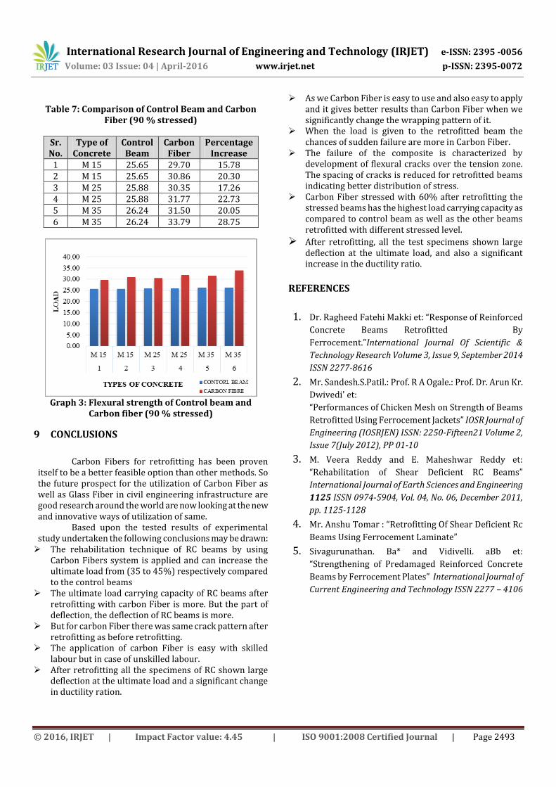
Table 7: Comparison of Control Beam and Carbon
Fiber (90 % stressed)
Sr. No.
Type of Concrete
Control Beam
Carbon Fiber
Percentage Increase
1 M 15 25.65 29.70 15.78 2 M 15 25.65 30.86 20.30 3 M 25 25.88 30.35 17.26 4 M 25 25.88 31.77 22.73 5 M 35 26.24 31.50 20.05 6 M 35 26.24 33.79 28.75
Graph 3: Flexural strength of Control beam and
Carbon fiber (90 % stressed)
9 CONCLUSIONS
Carbon Fibers for retrofitting has been proven
itself to be a better feasible option than other methods. So the future prospect for the utilization of Carbon Fiber as well as Glass Fiber in civil engineering infrastructure are good research around the world are now looking at the new and innovative ways of utilization of same.
Based upon the tested results of experimental study undertaken the following conclusions may be drawn: The rehabilitation technique of RC beams by using
Carbon Fibers system is applied and can increase the ultimate load from (35 to 45%) respectively compared to the control beams
The ultimate load carrying capacity of RC beams after retrofitting with carbon Fiber is more. But the part of deflection, the deflection of RC beams is more.
But for carbon Fiber there was same crack pattern after retrofitting as before retrofitting.
The application of carbon Fiber is easy with skilled labour but in case of unskilled labour.
After retrofitting all the specimens of RC shown large deflection at the ultimate load and a significant change in ductility ration.
As we Carbon Fiber is easy to use and also easy to apply and it gives better results than Carbon Fiber when we significantly change the wrapping pattern of it.
When the load is given to the retrofitted beam the chances of sudden failure are more in Carbon Fiber.
The failure of the composite is characterized by development of flexural cracks over the tension zone. The spacing of cracks is reduced for retrofitted beams indicating better distribution of stress.
Carbon Fiber stressed with 60% after retrofitting the stressed beams has the highest load carrying capacity as compared to control beam as well as the other beams retrofitted with different stressed level.
After retrofitting, all the test specimens shown large deflection at the ultimate load, and also a significant increase in the ductility ratio.
REFERENCES
1. Dr. Ragheed Fatehi Makki et: “Response of Reinforced
Concrete Beams Retrofitted By
Ferrocement.”International Journal Of Scientific &
Technology Research Volume 3, Issue 9, September 2014
ISSN 2277-8616
2. Mr. Sandesh.S.Patil.: Prof. R A Ogale.: Prof. Dr. Arun Kr.
Dwivedi' et:
“Performances of Chicken Mesh on Strength of Beams
Retrofitted Using Ferrocement Jackets” IOSR Journal of
Engineering (IOSRJEN) ISSN: 2250-Fifteen21 Volume 2,
Issue 7(July 2012), PP 01-10
3. M. Veera Reddy and E. Maheshwar Reddy et:
“Rehabilitation of Shear Deficient RC Beams”
International Journal of Earth Sciences and Engineering
1125 ISSN 0974-5904, Vol. 04, No. 06, December 2011,
pp. 1125-1128
4. Mr. Anshu Tomar : “Retrofitting Of Shear Deficient Rc
Beams Using Ferrocement Laminate”
5. Sivagurunathan. Ba* and Vidivelli. aBb et:
“Strengthening of Predamaged Reinforced Concrete
Beams by Ferrocement Plates” International Journal of
Current Engineering and Technology ISSN 2277 – 4106