Embed Size (px)
Citation preview

EPRI WORKSHOP Charlotte, NC July 27, 2004
1
CONTINUOUS AUTOMATED FLUX MONITORING FOR TURBINE
GENERATOR ROTOR CONDITION ASSESSMENT
J. Kapler, S. Campbell, M. Credland Iris Power Engineering Inc.
Toronto, Canada Abstract Flux monitoring via permanently mounted air gap flux probes is a proven technology in synchronous machines to determine if turn-to-turn shorts have occurred in the rotor winding. Flux measurements are the most powerful means of monitoring the condition of rotor windings on-line and can provide information on the integrity of the rotor winding inter-turn insulation. This information is critical in planning maintenance, explaining abnormal vibrations, and verifying new and rewound rotor integrity. To maximize the sensitivity to shorted turns in all rotor slots, the signals from the flux probe needs to be measured under different load conditions ranging from no load to full load. At a zero crossing of the total flux (which is a function of the real and reactive load of the machine), the sensitivity to the leakage flux is highest. Thus, flux readings are taken at various load points depending on the number of slot pairs in a pole pair. With the waveforms digitally recorded at each load step, specialized software can determine the number of shorted turns in each slot, as well as identify the slots with the shorts. Traditionally, flux measurements have been done utilizing portable instrumentation to digitize the signals and specialized software or expert interpretation. With cost effective modern electronics now available, the rotor flux test lends itself to automated data collection via a permanently connected instrument. In automated plants where generator load data is available, integrating a permanently connected flux monitor with generator load data and operating conditions can completely automate flux measurements, and guarantee the collection of accurate and trendable data. In addition, automated software can directly interpret the collected flux data, providing alarms to plant staff. This paper will describe the implementation of such a device and a case study that demonstrates the effectiveness of automated rotor flux monitoring. Shorted turn experience Recent review of generator reliability at US nuclear plants for the period 1990 to2002 indicates that rotor shorted turns do not frequently cause unit outages or costly repairs [1]. However, the most recent cases of shorted turns on four pole rotors at South Texas Project and at Diablo Canyon plants demonstrate that rotor shorted turns can result in significant production losses and high corrective maintenance cost [1]. The increased shaft vibrations from shaft unbalance due to shorted turns resulted in resonant responses

EPRI WORKSHOP Charlotte, NC July 27, 2004
2
in main terminal boxes and at main output terminals. In addition to unit outage losses, the corrective actions required rotor replacements and expensive rotor rewinds. Turbine generator rotor consists of s solid forging made from magnetic alloy steel and copper windings, assembled in slots machined in the forging. The winding is secured in slots by steel, bronze or aluminum wedges; at each end strong retaining rings support the end sections of the winding and prevent their breakage due to centrifugal forces imposed on a rotor at 3600 or 1800 rpm. A common issue with rotors is the exposure of winding copper and insulation to high centrifugal loads and thermal expansion forces, leading to breaks in winding insulation and to copper cracking and dusting. Modern rotor winding insulation is most frequently made from epoxy/polyester glass/Nomex laminate strips for interturn separation and molded channels for insulation to ground in rotor slots. In the end winding additional insulation blocking is used to mechanically support the coils and a molded insulation ring is assembled from laminate materials to insulate the top turns from the retaining rings. Slip planes are provided in regions where the largest relative thermal expansion are expected; this reduces the risk to insulation damage and limits the shaft thermal unbalance and excessive vibrations. The rotor insulation must withstand electrical, mechanical, thermal and environmental stresses, including:
- Mechanical wear, distortion, breakage and migration due to centrifugal mechanical loading and thermally induced expansion and contraction cyc les;
- Overheating due to overloading/over excitation and inadequate or diminished cooling. Local overheating may occur at high resistance braze joints and at shorted turns;
Four Pole Rotor with ventilation slots and balance holes

EPRI WORKSHOP Charlotte, NC July 27, 2004
3
- Contamination from copper dusting, or induced from ventilation, bridges creep distances with conductive deposits resulting in surface tracking between turns or to ground;
- Over voltages from voltages induced from system events or from firing circuits in static exciters can puncture turn and ground insulation in regions already weakened from other causes
The condition of the rotor winding insulation is difficult to assess during minor or major generator maintenance outages. Access to the winding is severely restricted without removal of the retaining rings and winding wedges. The off-line tests for detection of shorted turns and ground fault locations can also be frustratingly ineffective due to frequently intermittent nature of faults at speed and at standstill. On-line testing has been available for some time for detection of shorted turns in rotor windings [2, 3]. It is based on monitoring of stray (or leakage) flux, which develops across winding slots when the excitation current flows through the rotor winding. The stray flux is proportional to the total ampere-turns in each slot. If shorts develop between turns in any slot, then the ampere-turns in that slot drop and the stray flux across that slot is reduced. The magnitudes of these stray fluxes can be measured by measuring the induced voltages in a small induction coil mounted in the air gap at a suitable distance from the rotor surface. The shorted turns in the winding can then be identified by observing the differences in the induced voltages from sound and faulted winding slots. The main challenge in these measurements is to overcome the interference of the relatively weak stray fields across the individual slots by the main air-gap flux in working generators. The leading technique, described by GeneratorTech [3], uses the property of the main flux to change its shape and distribution on the rotor surface as a function of the generator output. At no-load, rated voltage excitation, the main flux distribution will approximate trapezoidal distribution in the air gap, with the zero magnitudes in the neutral, or Q axis, and the peak magnitude centered in the middle of the pole, or D axis. As the generator output increases, the armature reaction from the stator load current and the rotor load angle reshape the main resulting air -gap flux. The zero flux magnitude, or zero crossing point, will be shifting from the coil side in a slot that is farthest from a pole, toward the coil sides that are closer to the same pole, as the generator load increases. At the zero crossings of the main flux, the interference with the stray flux across a winding slot is at a minimum. The induced voltage in the stray flux coil over the slot at zero crossing will most accurately indicate the total ampere-turns in that slot and thereby the condition of turn insulation in the same slot. Software programs have been developed for recording of the test data, automatic analysis of the waveforms and for the indication of shorted turns [3].

EPRI WORKSHOP Charlotte, NC July 27, 2004
4
Contiuous Flux Monitor Traditionally the test for shorted turns requires the use of portable instrument connected to a permanently mounted flux probe. In addition, the test requires generator load changes over significant range for complete survey of all slots in the lead section of a pole winding. The requirement for the load changes often limits the opportunity for using the test at regular intervals to detect an increase in the number of shorted turns and planning for a corrective action. Modern electronics enabled the development of instruments which can be permanently connected to flux probes for automatic collection of the data. The FluxTracT M instrument can collect data remotely from the user’s office with Windows-based ‘TracCon’ software, which eliminates the need for costly and inconvenient generator load manipulations during each shorted turn detection test. The advantages of the continuous and automated monitoring for flux measurements can be summarized:
- Extensive re-organization in the utility industry has reduced the availability of site
operations/maintenance personnel as well as the size of supporting engineering and testing groups. Regular periodic tests for trending of shorted turn data have become more difficult to schedule and the desired test generator output points often interfere with the optimized revenue generation. The automated testing capability reduces the overall test costs and facilitates the test data to be collected in the normal operating regime, as the desired load points become available.
- The system can monitor up to four generators at a plant. The data can be collected remotely by Windows based software from the user’s office on each unit at convenient generator load points. This eliminates the need time consuming site tests and reduces the maintenance and test costs. The FluxTrac can be integrated in the overall plant monitoring system, providing accurate and reliable data for trending of rotor winding shorted turns.
- The data can be automatically analyzed for detection and trending of shorted turns with an already available expert computer software. The plant operators and maintenance personnel obtain early warnings of the developing problems and provides them with opportunities to schedule the required preventive or corrective maintenance.

EPRI WORKSHOP Charlotte, NC July 27, 2004
5
Pole A
Pole B
SlotLeakage
Flux
QuadratureAxis
Flux Probe
Figure 1: FluxTrac installed at convenient location in plant
Figure 2: TracCon Screen Capture

EPRI WORKSHOP Charlotte, NC July 27, 2004
6
The contiuous flux monitoring system is an advanced micro controller based instrument designed to monitor sequentially up to four flux probes, or four generators rotors at a plant. The instrument can be calibrated for a wide range of input signal levels and can process signals from existing wedge mounted probes from most manufacturers. The data acquisition software has a range of computer connection options and can be operated either locally or from a remote location to collect and store flux data on demand. The test data can be acquired over a range of generator outputs during normal service, on run-ups or run-downs, without the need for special test conditions and connection of manual testing instrumentation. The data is compatible with existing portable instrumentation. The software output is a text file that can be analyzed via a spreadsheet program of directly imported into available third party analysis software, such as from GeneratorTech. The software can be fully automated through SCADA or plant control systems to collect the flux data at pre-programmed generator load points[4]. Case Study FluxTrac monitor has been installed for monitoring of four generators at an eight unit combined cycle generating plant. Three of the monitored generators are powered by gas turbines, one by a steam turbine. These are daily peaking units, seldom used over night or on weekends.
Figure 3: Excel plot of on-line Flux data

EPRI WORKSHOP Charlotte, NC July 27, 2004
7
Machine Machine Type
Winding Type
Manufacturer
Year of Install
Rated Voltage (kV)
Rated Power (MW)
Speed (RPM)
Unit 1 Turbo Generator
Epoxy Mica
Siemens 1988 13.8 115 3600
Unit 2 Turbo Generator
Epoxy Mica
Siemens 1988 13.8 115 3600
Unit 3 Turbo Generator
Epoxy Mica
Siemens 1991 13.8 115 3600
Unit 4 Turbo Generator
Epoxy Mica
ABB 1990 18 165 3600
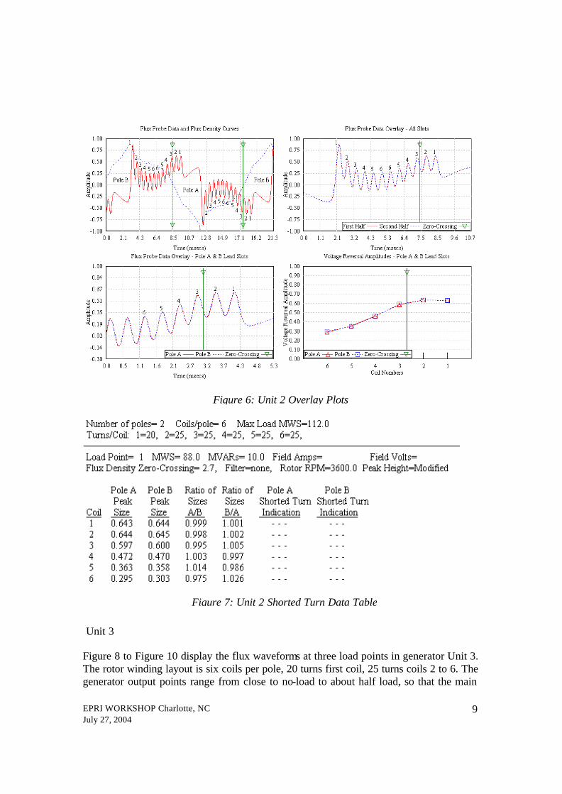
The inputs to the system are from the flux probes supplied by a third party: one probe installed on a stator winding slot wedge in each generator bore. Units 1 and 2 The Flux Probe Data and Flux Density Curves on generators 1 and 2 are shown in Figures 4 to 7. Unit 1 and 2 generators have the same two pole rotor design, having six winding coils per pole. The plots flux density curves are shown at two different loads, indicating the zero crossing of the main flux at slots 4 and 3, respectively. The plots indicate clearly, that the on-line system is collecting data accurately for analysis by third party software program. The output from the analyses confirms that there are no indications of any shorted turns in the vicinity of the slots 4 and 3 on either generator. The flux waveform over the surface of the poles A and B indicate also that the pole surfaces under the flux probes are smooth (uniform air gap), i.e. there are no damper winding slots or air ventilation scoops to cause the flux distortions over the poles.

EPRI WORKSHOP Charlotte, NC July 27, 2004
8
Figure 4: Unit 1 Flux Probe Data
Figure 5: Unit 2 Flux Probe Data
EPRI WORKSHOP Charlotte, NC July 27, 2004
9
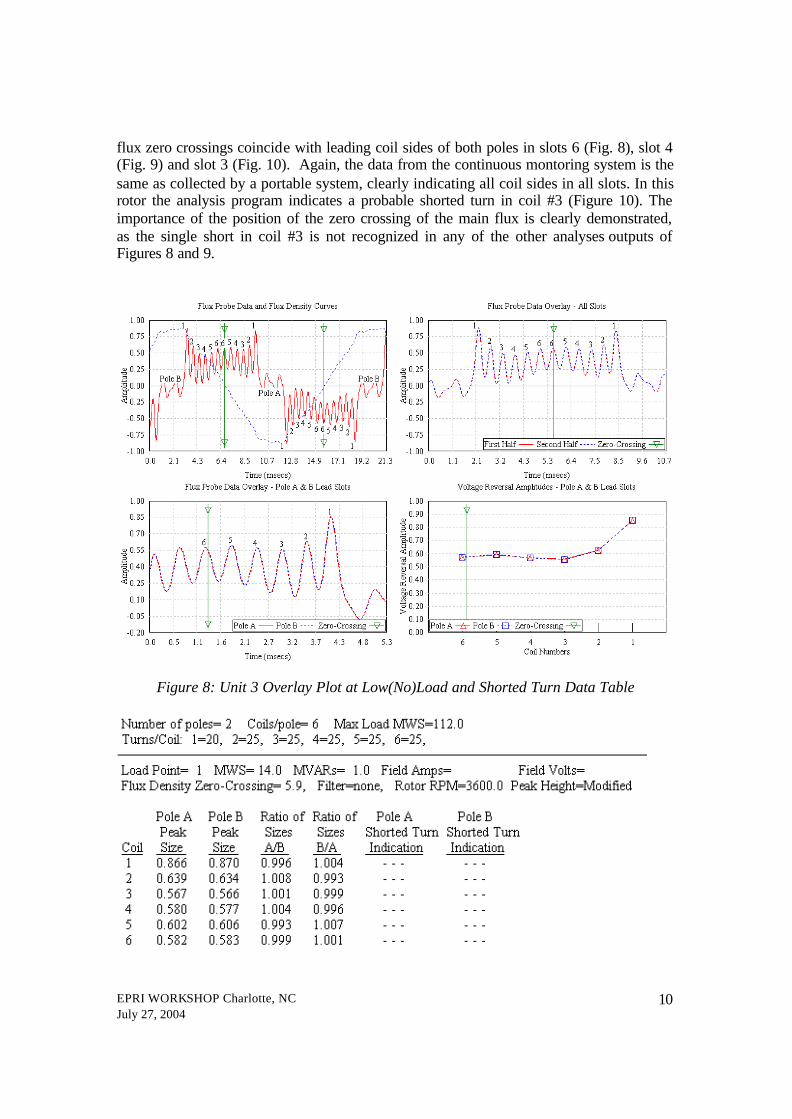
Unit 3 Figure 8 to Figure 10 display the flux waveforms at three load points in generator Unit 3. The rotor winding layout is six coils per pole, 20 turns first coil, 25 turns coils 2 to 6. The generator output points range from close to no-load to about half load, so that the main
Figure 6: Unit 2 Overlay Plots
Figure 7: Unit 2 Shorted Turn Data Table
EPRI WORKSHOP Charlotte, NC July 27, 2004
10
flux zero crossings coincide with leading coil sides of both poles in slots 6 (Fig. 8), slot 4 (Fig. 9) and slot 3 (Fig. 10). Again, the data from the continuous montoring system is the same as collected by a portable system, clearly indicating all coil sides in all slots. In this rotor the analysis program indicates a probable shorted turn in coil #3 (Figure 10). The importance of the position of the zero crossing of the main flux is clearly demonstrated, as the single short in coil #3 is not recognized in any of the other analyses outputs of Figures 8 and 9.
Figure 8: Unit 3 Overlay Plot at Low(No)Load and Shorted Turn Data Table

EPRI WORKSHOP Charlotte, NC July 27, 2004
11
Figure 9: Unit 3 Overlay Plot at 38MW and Shorted Turn Data Table

EPRI WORKSHOP Charlotte, NC July 27, 2004
12
Figure 10: Unit 3 Overlay Plot at 67MW and Shorted Turn Data Table

EPRI WORKSHOP Charlotte, NC July 27, 2004
13
The flux wave shape over the pole regions indicates some discontinuities on the pole surfaces under the flux probe. We are not familiar with the design details of the forging machining. It is likely that the rotor includes the full length damper winding and has shallow slots in the poles, or has some other forging machining feature in the vicinity of the flux probe. However, the continuous system has no difficulty properly plotting the flux density curves and the analysis program correctly numbers the winding slots. This is essential for comparison of the magnitudes of the induced voltages in leading coil sides of poles A and B. The differences in these magnitudes are indicators of shorted turns. Unit 4 Unit 4 flux probe data and flux density curves are shown in Figures 11 and 12. Figure 11 is flux density trace from the continuous system and Figure 12 from a standard manual test. The traces at 161MW output are identical, virtual overlay. The small voltage signal at the pole center is consistent with a shallow slot, containing perhaps a strip of full length damper winding.
Figure 11: FluxTrac Plot Data Unit 4 at 161MW

EPRI WORKSHOP Charlotte, NC July 27, 2004
14
Figure 12: Manual Plot Data Unit 4 at 161MW Some difficulties of current measuring systems to interpret data from rotors of different designs have been reported by other researchers[5]. Detailed design features such as winding layout, slot dimensions, wedge materials, damper winding arrangements, ventilation passages machined in forgings, may influence the flux density distributions under a flux search coil. These need to be identified for their possible influences on analyses results. Further work is under way to enhance the data interpretation and eliminate any false diagnosis of shorted turns from continuous on-line monitoring of rotor windings. Conclusion A continuous automatic instrument has been developed and is available for monitoring of stray flux wave forms in generator air gaps, which are used in shorted turn detection and trending in rotor windings. Up to four flux search coils can be monitored by one FluxTrac instrument at a plant. The measurements can be remotely triggered at selectable generator load points and data stored for processing by analytical software. This system automates the collection of flux data to find rotor winding shorted turns.

EPRI WORKSHOP Charlotte, NC July 27, 2004
15
References
1. EPRI, Life Cycle Management Planning Sourcebooks, Volume 5: Main Generator, Final Report 1007423, July 2003
2. Albright, D. R. “Interturn Short-Circuit Detector for Turbine-Generator Rotor
Windings”, IEEE Transactions on Power Apparatus and Systems, Vol. PAS-90 Number 2, March/April 1971
3. Donald R. Albright, David J. Albright and James D. Albright “Generator Fields
Winding Shorted Turn Detection Technology”, IRMC Conference, May 1999
4. Stone G. C., Lloyd B. A., On-line Condition Monitoring To Improve Generator Availability
5. Higgins, S. A. “Stray Flux Testing on Escom’s Generators”, Iris Rotating
machine Conference Conference, New Orleans, June 2004