Embed Size (px)
Citation preview
arX
iv:1
505.
0291
1v1
[cs.
IT]
12 M
ay 2
015
Resource Allocation in Full-Duplex
Communications for Future Wireless Networks
Lingyang Song∗, Yonghui Li†, and Zhu Han‡
∗School of Electrical Engineering and Computer Science, Peking University, Beijing, China
†School of Electrical and Information Engineering, The University of Sydney, Australia
†Electrical and Computer Engineering Department, University of Houston, USA
Abstract
The recent significant progress in realizing full-duplex (FD) systems has opened up a promising
avenue for improving quality of service (QoS) and quality ofexperience (QoE) in future wireless
networks. There is an urgent need to address the diverse set of challenges regarding different aspects of FD
network design, theory, and development. In addition to theself-interference cancelation signal processing
algorithms, network protocols such as resource managementare also essential in the practical design and
implementation of FD wireless networks. This article aims to present the latest development and future
directions of resource allocation in different full duplexsystems by exploring the network resources
in different domains, including power, space, frequency, and device dimensions. Four representative
application scenarios are considered: FD MIMO networks, FDcooperative networks, FD OFDMA cellular
networks, and FD heterogeneous networks. Resource management problems and novel algorithms in these
systems are presented, and key open research directions arediscussed.
I. INTRODUCTION
With more and more new multimedia rich services being introduced and offered to a rapidly grow-
ing population of global subscribers, there is an ever-increasing demand for higher data rate wireless
access, making more efficient use of the precious resource a crucial need. As a consequence, new
wireless technologies such as Long Term Evolution (LTE) andLTE-Advanced have been introduced.
These technologies are capable of providing high speed, large capacity, and guaranteed quality-of-
experience (QoE) mobile services [1], [2]. However, all existing wireless communication systems deploy
2
the half-duplex (HD) radios which transmit and receive the signals in two separate/orthogonal channels.
They dissipate the precious resources by employing either atime-division or a frequency-division du-
plexing. Though a full-duplex (FD) system, where a node can send and receive the signals at the same
time and frequency resources, offers the potential to double the spectral efficiency, for many years it
has been considered impractical. This is because the signalleakage from the local output to input may
overwhelm the receiver, thus making it impossible to extract the desired signal.
Recently, there has been a significant process in the self interference cancelation in FD systems.
Depending on the size of devices, it has been shown that the amount of self-interference and the extent
to which it can be canceled varies greatly, thus impacting the performance of different nodes in the
network differently. In [3], several interference cancelation mechanisms have been proposed. It was
shown experimentally that it is possible to adequately reduce the self interference to a certain level at
which the FD radios achieve a higher rate than the HD systems.In [4], new analog and digital cancelation
techniques were developed and implemented in an in-band FD WiFi radios. It is shown experimentally
that the self interference level can be reduced to the receiver noise floor. These significant progresses in
hardware design and signal processing techniques have presented a great potential for realizing the FD
communications in a near future for the next generation cellular networks.
Since the FD technology enables to explore another dimension of the network resources to increase the
network capacity, it requires the new design of network protocols and resource allocation algorithms in FD
communications systems. This promising opportunity has sofar inspired the rapid research development
in this area. In [5], the optimal power allocation among the FD source nodes was presented to maximize
the sum-rate of wireless FD bidirectional transmissions. In [6], the optimum power allocation schemes
subject to individual power constraints have been analytically obtained for a FD decode-and-forward
relay channel. In [7], the gain factor of amplify-and-forward relaying was optimized to maximize the
signal-to-interference and noise ratio (SINR) and at the same time prevent the oscillation effects at the
relay caused by the residual interference.
Though resource management is essential to system performance, most existing work mainly focuses on
power allocation in FD wireless networks. Actually, many other network resources in space, frequency,
and device dimensions can be explored in FD networks to further reduce the self interference and at
the same time improve the system spectrum efficiency. In thisregard, there is a significant need to
3
address the various challenges in the theory, design, and development of FD systems. In this article,
we comprehensively discuss the novel resource allocation algorithms for FD communication systems to
optimize their network performance. In particular, we focus on the following major application scenarios:
• FD MIMO systems (FD-MIMO): Each node in the FD-MIMO systems is equipped with a FD radio
and multiple antennas, each of which can be used for transmission and reception. This enables a
simultaneous bidirectional information exchange betweentwo nodes. The resource allocation in such
systems involves the allocation of spatial domain resources, such as antennas [8], [9].
• FD relay networks (FD-Relay): The basic FD-Relay network structure consists of one source and
destination pair, and one relay node. Both the source and destination nodes are HD, but the relay
is operated in the FD mode. The resource allocation in such systems involves the allocations of
antennas, relays and power [10]–[14].
• FD OFDMA networks (FD-OFDMA): It is composed of a FD base station (BS) using OFDM, and
multiple single antenna HD uplink and downlink users. The uplink and downlink users can form a
transmit-receive pair to communicate with the FD BS. The keychallenge in such a network is how
to optimally pair the uplink and downlink users for each OFDMsubcarrier in communicating with
the FD BS [15].
• FD heterogenous networks (FD-HetNet): In such a network, the macro base stations (MBSs) and
femto access points (FAPs) are equipped with FD radios. In contrast to the traditional HetNet systems
where FAPs in the adjacent cells typically do not interfere much with each other, in FD-HetNet the
simultaneous uplink and downlink communications between the users and MBSs/FAPs can lead
strong interference among the FAPs [16].
Obviously, in different FD application scenarios, different network resources need to be optimized
by exploring different resource allocation algorithms. Inthis magazine paper, we demonstrate, in the
above mentioned FD application scenarios, new research challenges in resource allocation and network
protocols, and present the latest promising research development to resolve these technical challenges.
Some potential research directions and open problems will be also discussed.
The rest of article is organized as follows: Section II reviews the basics of FD communications, and
presents main application scenarios. The major resource allocation problems in these applications are
discussed in Section III. Then we provide two example scenarios in Section IV on link selection for FD-
4
MIMO networks, and user pairing and subcarrier assignment for FD-OFDMA. In Section V, we draw
the main conclusions, and also discuss future research directions.
II. FULL -DUPLEX COMMUNICATION BASICS AND APPLICATIONS
In this section, we first briefly introduce FD communication systems, and then, present possible
application scenarios.
A. Basics of Full-Duplex Communication
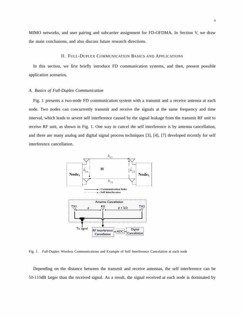
Fig. 1 presents a two-node FD communication system with a transmit and a receive antenna at each
node. Two nodes can concurrently transmit and receive the signals at the same frequency and time
interval, which leads to severe self interference caused bythe signal leakage from the transmit RF unit to
receive RF unit, as shown in Fig. 1. One way to cancel the self interference is by antenna cancellation,
and there are many analog and digital signal process techniques [3], [4], [7] developed recently for self
interference cancellation.
Fig. 1. Full-Duplex Wireless Communications and Example ofSelf Interference Cancelation at each node
Depending on the distance between the transmit and receive antennas, the self interference can be
50-110dB larger than the received signal. As a result, the signal received at each node is dominated by
5
the self interference. This will overwhelm the AD/DA conversion process due to its limited dynamic
range. Consequently, the effective bits for the desired received signal is much smaller, and the resulting
SINR is low. Therefore, the self interference needs to be mitigated before the ADC in analog circuit.
After the analog self interference cancelation, the remaining interference can be further reduced by the
active digital cancelation. However, due to the practical constraint, the interference cannot be completely
suppressed. In the literature, depending on the self-interference cancelation techniques, the residual self-
interference (RSI) can be modeled as AWGN, Rayleigh or Rician distributed variables [5], [6].
As a result, the signals received at each node are a combination of the signal transmitted by the other
source, the RSI, and the noise. As shown in Fig. 1, at node1, it has
y1 =√p2h21x2 +
√p1h̃11x1 + n1, (1)
wherep1 and p2 represent the transmit power at each node ,h21 denotes the communication channel
from node2 to node1, h̃11 represents the interference channel, andn1 denotes the noise term. Thus, the
instantaneous received SINR can be calculated as
γ1 =|h21|2p2
∣
∣
∣h̃11
∣
∣
∣
2
p1 +N0
. (2)
From (2), it is obvious that the instantaneous SINR decreases as the RSI increases. As indicated in (2),
the values of|h21|2, |h̃11|2, P1, andP2 have a strong impact on SINR, and in turn will affect the system
performance significantly, while in traditional HD communication system, the major effects come from
the transmit side only. Therefore, the effective resource allocation that can further reduce the effects of
RSI is crucial for FD communication and networks. In the nextsections, we will present various resource
allocation algorithms for the FD wireless systems.
B. Key Full Duplex Communications Networks
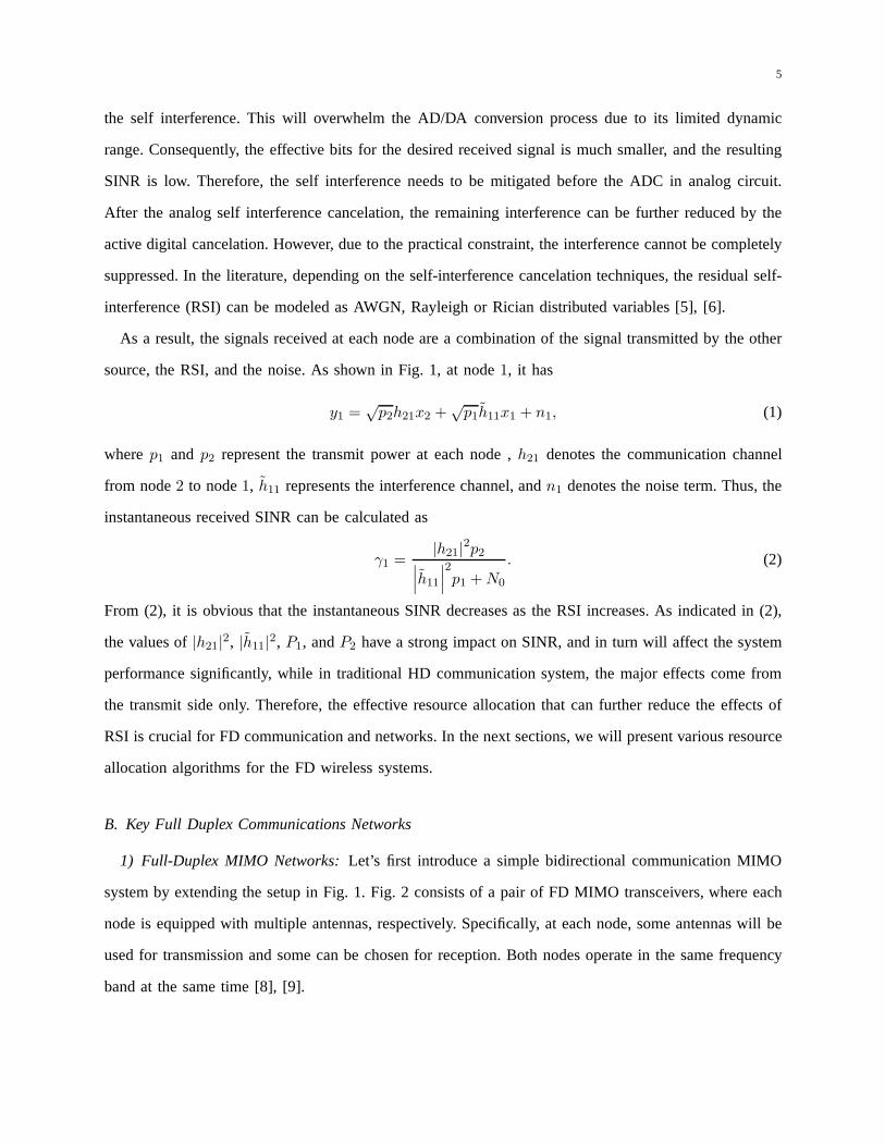
1) Full-Duplex MIMO Networks: Let’s first introduce a simple bidirectional communicationMIMO
system by extending the setup in Fig. 1. Fig. 2 consists of a pair of FD MIMO transceivers, where each
node is equipped with multiple antennas, respectively. Specifically, at each node, some antennas will be
used for transmission and some can be chosen for reception. Both nodes operate in the same frequency
band at the same time [8], [9].
6
ABh
BAh
Fig. 2. Full-Duplex MIMO Networks
2) Full-Duplex Relay Networks: Relaying technology has been widely used in many communications
systems. Traditional relay systems, where a source node communicates with a destination node through
one or multiple relays, operates in the HD mode. This leads tothe loss of spectral efficiency because the
relay node needs to receive and retransmit the signals in theorthogonal resources. By equipping the relay
nodes with FD radios, the relay can receive and retransmit signals simultaneously, and thus the spectral
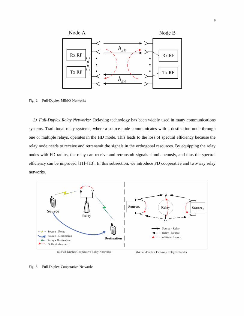
efficiency can be improved [11]–[13]. In this subsection, weintroduce FD cooperative and two-way relay
networks.
Source
Destination
Relay
Source - Relay
Relay - Destination
Self-interference
Source - Destination
Source1 Source2Relay
Source - Relay
Relay - Source
self-interference
(a) Full-Duplex Cooperative Relay Networks (b) Full-Duplex Two-way Relay Networks
Fig. 3. Full-Duplex Cooperative Networks
7
Full-Duplex Cooperative Relay Networks: Fig. 3 (a) illustrates a simple FD relay network consisting
of one HD source, one HD destination, and one FD cooperative relay node. Both the source and relay
nodes use the same time-frequency resource and the relay nodes work in the FD mode with two antennas
(one for transmission and one for reception). The communication process can be briefly described below:
• The source transmits signals to both the FD relay and destination;
• At the same time the FD relay forwards the signals received inthe previous time slots to the
destination.
As a special case, when there is no direct channel link between the source and destination, the scenario
in Fig. 3 (a) can be reduced to FD one-way relay networks.
Full-Duplex Two-way Relay Networks Similar to the FD one way relay network, employing the FD
relaying in two-way relay networks can also greatly improveits performance [11]. As shown in Fig. 3 (b),
the FD two-way relay system consists of two sources, and one relay node and all nodes work in the FD
mode with two antennas, one for transmission and one for reception. The direct link between two source
nodes does not exist. The communication process consists oftwo phases:
• Two source nodes transmit signals to the relay node, while receiving the signal sent from the relay
node at the same time;
• The relay broadcasts the signals received in the previous time slot to both source nodes and
meanwhile receiving the signals from the sources.
a b
Transmitter Receiver
Antennas
1 2 K
Subcarriers
Base Station
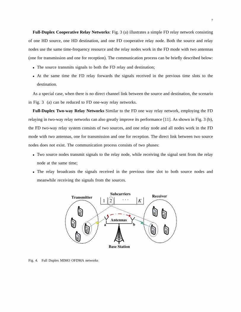
Fig. 4. Full Duplex MIMO OFDMA networks
8
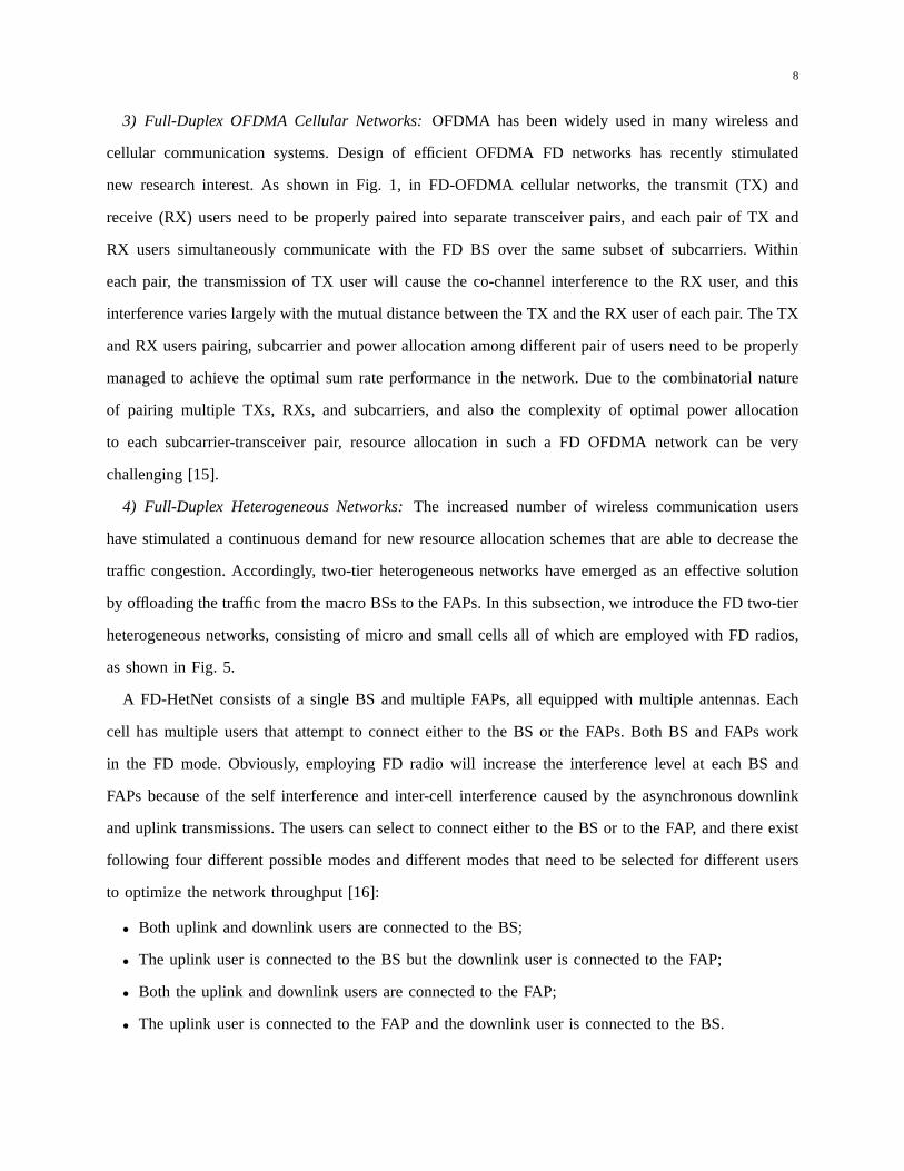
3) Full-Duplex OFDMA Cellular Networks: OFDMA has been widely used in many wireless and
cellular communication systems. Design of efficient OFDMA FD networks has recently stimulated
new research interest. As shown in Fig. 1, in FD-OFDMA cellular networks, the transmit (TX) and
receive (RX) users need to be properly paired into separate transceiver pairs, and each pair of TX and
RX users simultaneously communicate with the FD BS over the same subset of subcarriers. Within
each pair, the transmission of TX user will cause the co-channel interference to the RX user, and this
interference varies largely with the mutual distance between the TX and the RX user of each pair. The TX
and RX users pairing, subcarrier and power allocation amongdifferent pair of users need to be properly
managed to achieve the optimal sum rate performance in the network. Due to the combinatorial nature
of pairing multiple TXs, RXs, and subcarriers, and also the complexity of optimal power allocation
to each subcarrier-transceiver pair, resource allocationin such a FD OFDMA network can be very
challenging [15].
4) Full-Duplex Heterogeneous Networks: The increased number of wireless communication users
have stimulated a continuous demand for new resource allocation schemes that are able to decrease the
traffic congestion. Accordingly, two-tier heterogeneous networks have emerged as an effective solution
by offloading the traffic from the macro BSs to the FAPs. In thissubsection, we introduce the FD two-tier
heterogeneous networks, consisting of micro and small cells all of which are employed with FD radios,
as shown in Fig. 5.
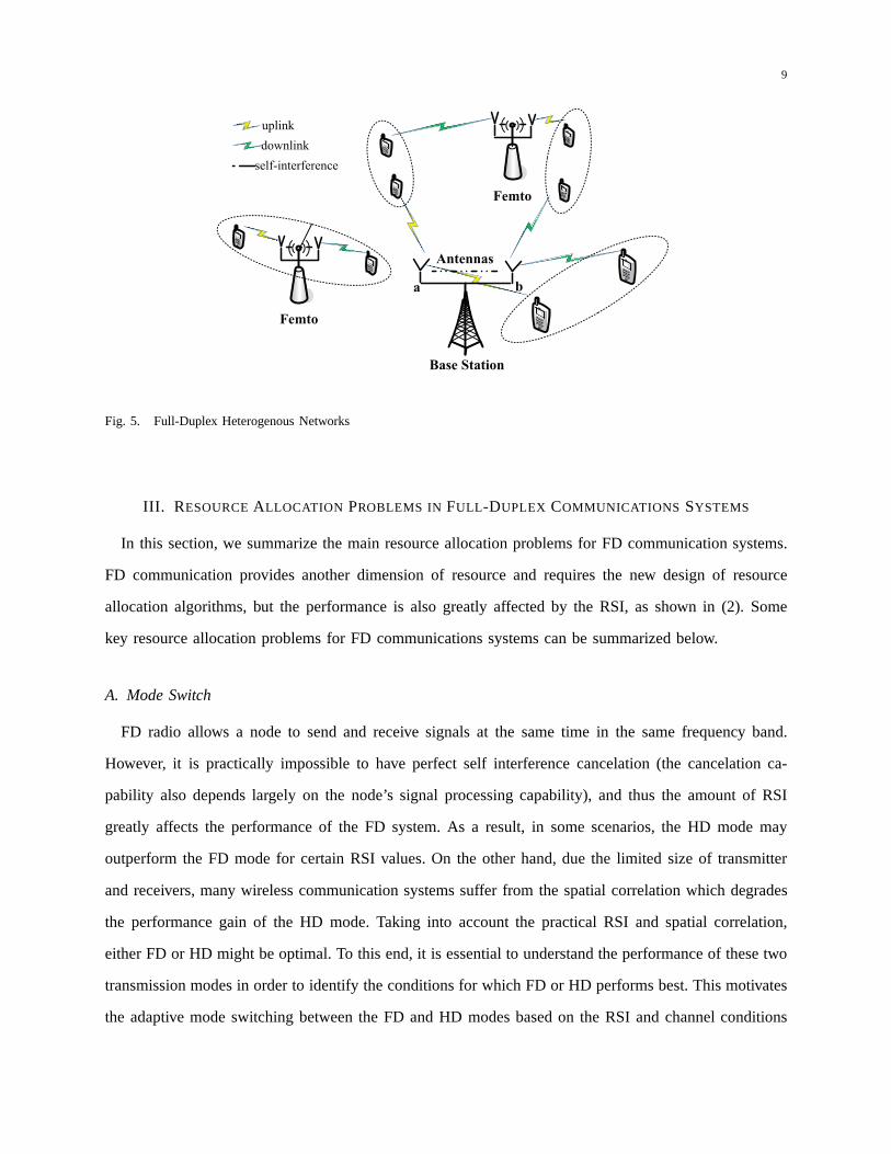
A FD-HetNet consists of a single BS and multiple FAPs, all equipped with multiple antennas. Each
cell has multiple users that attempt to connect either to theBS or the FAPs. Both BS and FAPs work
in the FD mode. Obviously, employing FD radio will increase the interference level at each BS and
FAPs because of the self interference and inter-cell interference caused by the asynchronous downlink
and uplink transmissions. The users can select to connect either to the BS or to the FAP, and there exist
following four different possible modes and different modes that need to be selected for different users
to optimize the network throughput [16]:
• Both uplink and downlink users are connected to the BS;
• The uplink user is connected to the BS but the downlink user isconnected to the FAP;
• Both the uplink and downlink users are connected to the FAP;
• The uplink user is connected to the FAP and the downlink user is connected to the BS.
9
Fig. 5. Full-Duplex Heterogenous Networks
III. R ESOURCEALLOCATION PROBLEMS IN FULL -DUPLEX COMMUNICATIONS SYSTEMS
In this section, we summarize the main resource allocation problems for FD communication systems.
FD communication provides another dimension of resource and requires the new design of resource
allocation algorithms, but the performance is also greatlyaffected by the RSI, as shown in (2). Some
key resource allocation problems for FD communications systems can be summarized below.
A. Mode Switch
FD radio allows a node to send and receive signals at the same time in the same frequency band.
However, it is practically impossible to have perfect self interference cancelation (the cancelation ca-
pability also depends largely on the node’s signal processing capability), and thus the amount of RSI
greatly affects the performance of the FD system. As a result, in some scenarios, the HD mode may
outperform the FD mode for certain RSI values. On the other hand, due the limited size of transmitter
and receivers, many wireless communication systems sufferfrom the spatial correlation which degrades
the performance gain of the HD mode. Taking into account the practical RSI and spatial correlation,
either FD or HD might be optimal. To this end, it is essential to understand the performance of these two
transmission modes in order to identify the conditions for which FD or HD performs best. This motivates
the adaptive mode switching between the FD and HD modes basedon the RSI and channel conditions
10
to maximize the ergodic capacity [17].
B. Power Control
Power control has been a commonly used approach in multi-user communication systems to optimize
system performance such as link data rate, network capacityand coverage. Unlike traditional wireless
networks, FD communication suffers from the RSI, and thus, increasing transmit power can improve
the signal strength in the receiver side, but on the other side increases the RSI at its own receiver, as
indicated in (2). Therefore, due to the existence of RSI, corresponding power control algorithm needs
to be properly redesigned in order to maximize system performance of all users. The different power
constraints, e.g.total or individual transmit power, will lead to different designs and final solutions [13].
Moreover, as detailed below, different FD systems require different power control algorithms:
• FD-MIMO: In bidirectional FD-MIMO communication, the antennas at the FD node are divided into
transmit and receive antenna sets, and water-filling power allocation can be applied at the transmit
antenna set to maximize the sum rate based on individual power constraint. The water-filling power
allocation at each nodes needs to take into account the self-interference from the transmit antenna
set to the receive antenna set at each node and the power pouring results at each node can be
significantly different;
• FD-Relay: In FD-Relay networks with individual power constraint at each relay, the relayed signals
are corrupted by the RSI, and thus, the received signals at the destination are the combination of
the desired signals plus RSI introduced at the relay node. Increasing the transmit power at the relay
will increase the power of desired signal at the destination, but on the other side it will increase the
RSI in the destination received signal. Therefore, there isan optimal transmit power at the relay to
maximize the performance at the receiver node;
• FD-OFDMA: For FD-OFDMA with one FD BS and HD multiple users, uplink (transmit) and
downlink (receive) users are paired to communicate with theFD BS at the same time. The transmit
power can be allocated at the BS side with total power constraint by splitting the power among all
the subcarriers for different user pairs. At the user side, power control needs to take into account
the inter-user distance among the transmit-receiver user pair. Thus, the optimal power control in the
FD-OFDMA system depends on many factors, which requires multi-dimensional optimization for
11
the BS and the mobile users [15];
• FD-HetNet: Similar to FD-OFDMA, the power control can be performed for the FD BS and FAPs
and HD users in FD-HetNet to optimize the network performance. However, both the inter-cell
interference and RSI need to be considered jointly in optimizing the overall network performance.
C. Transmit Beamforming
Transmit beamforming is a general signal processing technique used to control the directionality of
transmission in order to provide a large antenna array gain in the desired directions, and has been widely
applied in the 3rd and 4th generation wireless communication systems. To change the directionality of
the array when transmitting, a beamformer controls the phase and relative amplitude of the signal at the
transmitter in order to create a pattern of constructive anddestructive interference in the wave front. For
FD communications, it would be greatly beneficial to design the robust transmit beamforming algorithms
that can improve the signal strength at the receiver side, and meanwhile reduce the self interference
subject to various design criteria such as the minimum mean square error. Below are the discussions of
beamformer design for different FD systems.
• FD-MIMO: In this case, the transmit antenna set at each FD nodes can perform transmit beamforming
to simultaneously transmit information and reduce the interference to its own received signals. The
design is to jointly optimize the system sum rate.
• FD-OFDMA: In FD-OFDMA, the FD BS is equipped with multiple antennas, consisting of transmit
and receive antenna sets, while the users only operate in theHD transmission mode due to hardware
constraint. In this case, the BS can construct beamformer tosupport multiple users in the downlink
while maximizing the received SINRs at BS by minimizing the RSI. Besides, the beamforming design
also needs to consider appropriate pairing of downlink and uplink users, which also significantly
affect the self interference at the BS, and the co-channel interference among downlink and uplink
users.
D. Link Selection
For a FD communication system, each antenna can be configuredto transmit or receive the signals.
This will create multiple possible virtual links between two nodes, with one virtual link representing
12
the channel from a transmit antenna of one node to a receive antenna of the other. Since the FD
radio enables simultaneous bidirectional information exchange between two nodes, an important question
arisen in such a scenario is how to optimally select the link for each direction to optimize the system
performance. Obviously, the optimal selection requires exhaustive search among from all possible antenna
links. However, as the number of antennas increases, such a brute-force search suffers from very high
computational complexity, and thus, simple but near-optimal selection algorithms need to be developed.
Next let us discuss some selection algorithms for the FD-MIMO, FD-Relay, and FD-HetNet systems.
• Antenna selection in FD-MIMO systems: For FD-MIMO systems with NA andNB antennas equipped
at two nodes. Such a FD MIMO system will createNA × NB possible virtual links between two
nodes, with one virtual link representing the channel from atransmit antenna of a node to a receive
antenna of the other node. The challenge is to design the simple but (near) optimal bidirectional
link selection algorithm to optimize the bidirectional sumrate or sum symbol error rate (SER) [8],
[9].
• Joint antenna and relay selection in FD-Relay systems: In a general FD relay networks consisting
of one source, one destination, andN FD relays, and each antenna of the FD relay is able to
transmit/receive the signal. Hence, the source, relays, and destination form a number of virtual
end-to-end links. In this case, each antenna of the FD relay is able to transmit/receive the signal.
Each relay adaptively selects its TX antenna and RX antenna based on the instantaneous channel
conditions, and the optimal single relay with the optimal TX/RX antenna configuration is selected
to maximize the end-to-end SINR of the system [11], [13].
• Coordinated multiple point transmission: In FD HetNet, theusers can select to communicate with
the transmit/receive antenna of multiple available FD access points (BSs or FAPs) in a coordinated
way so as to form the joint multiple point transmission, improving spatial and frequency utilization
efficiency [16].
E. Subcarrier Allocation
In an OFDMA system, at each time slot, disjoint sets of subcarriers can be assigned to different
users based on some target objectives. The users then in turntransmit data by spreading the information
across the assigned subcarriers. In a FD-OFDMA network consisting of one FD BS withNf subcarriers,
13
Nu uplink users, andNd downlink users, a fundamental challenge arisen in such system is how to pair
uplink and downlink users, and allocate subcarrier across these user pairs, in order to optimize the network
performance. The subcarrier allocation involves allocating the different subsets of subcarriers to different
users by taking into account the RSI at the BS and the co-channel interference between the uplink and
downlink users within each user pair [15]. This is significantly different from the traditional subcarrier
allocation problem and present further research challenges in resource allocation.
Similarly, in FD-Relay networks, consisting of multiple source and destination nodes, and FD relay
nodes using OFDM transmission, the corresponding subcarriers should be properly allocated at the relay
for different source-destination pairs.
IV. RESOURCEALLOCATION EXAMPLES
In the following two subsections, we provide two example scenarios to illustrate how to conduct FD
resource allocation.
A. Bidirectional Antenna Link Selection for Full-Duplex MIMO Networks
In this section, we discuss in details the specific link selection problem and its near-optimal algorithms
for FD-MIMO systems [8], [9]. We consider a bidirectional communication scenario between a pair of
FD transceivers, nodesA andB, as illustrated in Fig. 2, where nodesA andB are equipped withNA and
NB antennas, respectively. Both nodes use the same frequency band at the same time for FD operation.
Each node employs only one transmit and one receive RF chain,and any antenna can be configured to
connect either transmit or receive RF chains. In the proposed simultaneous bidirectional link selection
scheme, two antenna links are selected for simultaneous bidirectional communications by choosing a pair
of transmit and receive antenna at both ends for each direction. Within each antenna pair, one antenna is
selected for transmission and one is for the reception to maximize the sum rate (Max-SR) or minimize
the sum symbol error rate (Min-SER), respectively.
1) Maximum Sum-Rate (Max-SR): In the Max-SR selection criterion, two communication linksfrom
the IT -th transmit antenna at node A to theJR-th receive antenna at node B and theJT -th transmit
antenna at node B to theIR-th receive antenna at node A, are selected to maximize the bidirectional
sum rate [8]. This is equivalent to select, among all the possible antenna configurations, the optimal
14
transmit-receive antenna pairs, denoted by(IT , IR) at nodeA and(JT , JR) at nodeB, to maximize the
sum rate
{(IT , JR), (IR, JT )} = argmax{
Rate(
γitjr)
+Rate(
γirjt)}
. (3)
We useRate(·) represents transmission rate,γitjr andγirjt to denote the corresponding instantaneous
SINR of the selected transmit-receive antenna pairs of nodes A to B and nodesB to A, respectively.
2) Minimum Sum-SER (Min-SER): In the Min-SER selection criterion, the bidirectional antenna links
are selected to minimize the sum SER,
{(IT , JR), (IR, JT )} = argmin{
SER(
γitjr)
+SER(
γirjt)}
, (4)
whereSER(·)represent the SER.
0 5 10 15 20 25 302
3
4
5
6
7
8
9
10
Ave
rage
sum
rat
e (b
ps/H
z)
Transmit power (dB)
N=3N=4N=5
0 5 10 15 20 25 3010
−8
10−7
10−6
10−5
10−4
10−3
10−2
10−1
Transmit power (dB)
Ave
rage
sum
SE
R
N=3N=4N=5
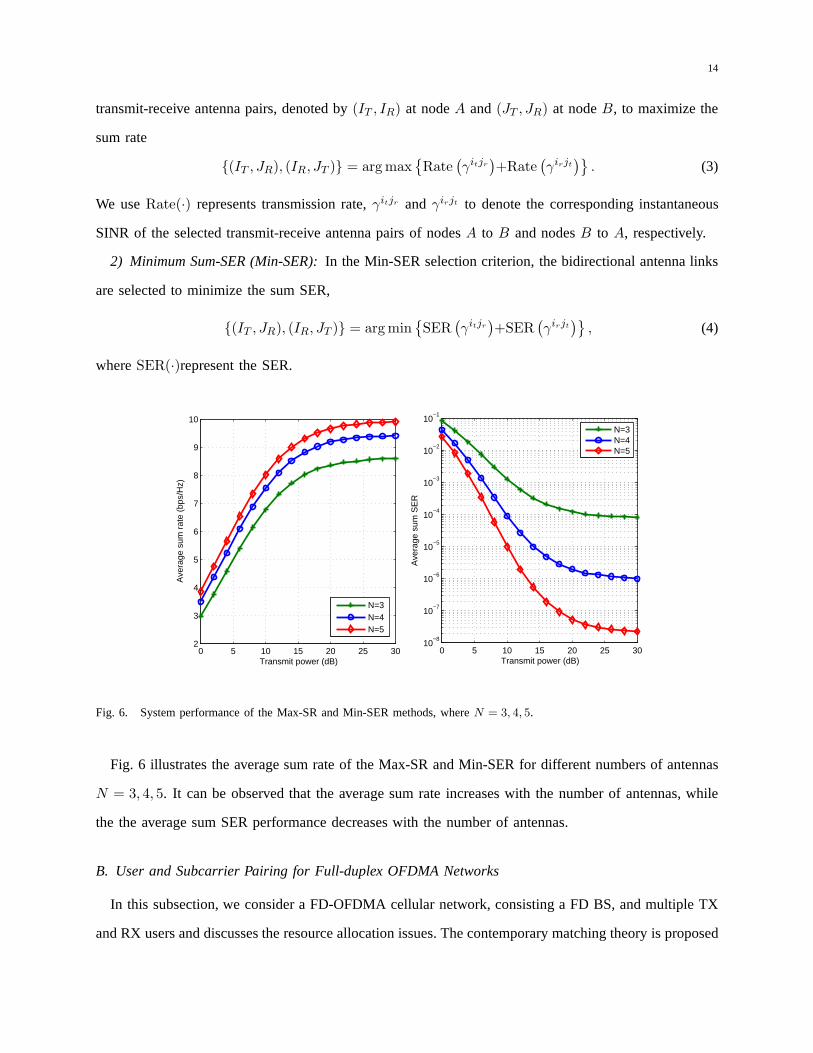
Fig. 6. System performance of the Max-SR and Min-SER methods, whereN = 3, 4, 5.
Fig. 6 illustrates the average sum rate of the Max-SR and Min-SER for different numbers of antennas
N = 3, 4, 5. It can be observed that the average sum rate increases with the number of antennas, while
the the average sum SER performance decreases with the number of antennas.
B. User and Subcarrier Pairing for Full-duplex OFDMA Networks
In this subsection, we consider a FD-OFDMA cellular network, consisting a FD BS, and multiple TX
and RX users and discusses the resource allocation issues. The contemporary matching theory is proposed
15
to solve the complicated resource pairing problems [15]. Asshown in Fig. 4, in FD-OFDMA cellular
networks, the BS needs to allocate a subset of non-overlapping subcarriers to each pair of users, so that
each pair of users and the BS form a FD transceiver unit, in which one user acts as a TX and the other
acts as a RX. Note that each subcarrier is assigned to a user pair only. Without loss of generality, we
assume that the BS is equipped with two antennasa andb, and multiple users each with one antenna.
To facilitate describing the user and subcarrier pairing process, define a three-dimensionalM×M×K
pairing matrixX = {0, 1}, wherexk,i,j = 1 denotes thatTXi andRXj are paired and use subcarrier
k. Our objective is to maximize the sum-rate of the system by jointly optimizing the pairing variables
{xk,i,j} and the power variables{ps,j,k}. The optimization problem can be formulated as:
max
K∑
k=1
M∑
i=1
M∑
j=1
Rate({xk,i,j},{ps,j,k})
s.t. each TX can only be paired with one RX, and vice versa,
each subcarrier can only be assigned to one transceiver unit, and vice versa,
the total transmit power of the BS is subject to its peak powerconstraintPs. (5)
The matching algorithm can be briefly described as follows. First, define a price for each SR unit and
set the price to zero. These prices are fictitious money without any physical meanings that are considered
as the matching cost for each TX. The price of any SR unit,SRk,j is the sum ofRXj ’s price and
subcarrierk’s price. Then in each step, anyTXi that is still not matched proposes to its most preferred
SRk,j according to the achieved sum-rate and the cost of the correspondingTXi-SR unit. If RXj or
subcarrierk receives offers from more than two TXs, they increase their prices with a price step number
until only one offer is received. WhenRXj and subcarrierk both receive only one offer, which comes
from TXi, they will be matched together. The matching algorithm is iterative and ends if all the TXs
are matched and no new offer is being made. This point is called theequilibrium point of the matching,
which also indicates that the convergence has been achieved.
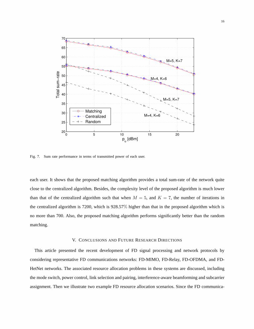
To evaluate the performance, the centralized solution is compared. Besides, a random matching algo-
rithm is utilized, in which the TXs, the RXs and the subcarriers are randomly matched with each other
while satisfying the system constraints. These two algorithms are considered as the upper and lower
bound solutions in terms of the complexity. Fig. 7 illustrates the total sum-rate vs. transmitted power of
16
0 5 10 15 2020
25
30
35
40
45
50
55
60
65
70
pu [dBm]
To
tal su
m−
rate
Matching
Centralized
Random
M=4, K=6
M=5, K=7
M=4, K=6
M=5, K=7
Fig. 7. Sum rate performance in terms of transmitted power ofeach user.
each user. It shows that the proposed matching algorithm provides a total sum-rate of the network quite
close to the centralized algorithm. Besides, the complexity level of the proposed algorithm is much lower
than that of the centralized algorithm such that whenM = 5, andK = 7, the number of iterations in
the centralized algorithm is 7200, which is 928.57% higher than that in the proposed algorithm which is
no more than 700. Also, the proposed matching algorithm performs significantly better than the random
matching.
V. CONCLUSIONS ANDFUTURE RESEARCHDIRECTIONS
This article presented the recent development of FD signal processing and network protocols by
considering representative FD communications networks: FD-MIMO, FD-Relay, FD-OFDMA, and FD-
HetNet networks. The associated resource allocation problems in these systems are discussed, including
the mode switch, power control, link selection and pairing,interference-aware beamforming and subcarrier
assignment. Then we illustrate two example FD resource allocation scenarios. Since the FD communica-
17
tion creates multiple possible virtual links between each node, we present simultaneous link selection for
FD-MIMO networks by Max-SR and Min-SER criteria; Besides, We also elaborate how matching theory
can be applied to solve the user and subcarrier pairing problems in FD-OFDMA cellular networks.
FD communication is a very promising technology, and there are many potential future research
directions in this area, for example,
• FD cognitive radio networks: In traditional cognitive radio networks, secondary users (SUs) typically
access the spectrum of primary users by a two-stage “listen-before-talk” protocol, i.e., SUs sense
the spectrum holes in the first stage before transmit in the second. With a FD radio, it allows
SUs to simultaneously sense and access the vacant spectrum.As a result, research topics such as
spectrum sensing algorithms, dynamic spectrum access, communication protocol design, etc, need
to be redeveloped [18];
• Physical-layer security: Physical layer security provides an alternative security solution by consider-
ing the physical characteristics of wireless links. Traditional opinion typically treats the interference
as a disadvantage, but in physical-layer security, interference can be utilized to interferer the ma-
licious nodes. In FD communication, the self-interferencecan be certainly reused to improve the
network secrecy capacity. Various research topics such as secrecy capacity analysis, power control,
beamforming, etc., are worth of further investigation.
REFERENCES
[1] L. Song and J. Shen,Evolved Network Planning and Optimiation for UMTS and LTE, Auerbach Publications, CRC Press,
2010.
[2] M. Dong, T. Kimata, K. Sugiura, K. Zettsu, “Quality-of-Experience (QoE) in Emerging Mobile Social Networks,”IEICE
Transactions vol. 97, no. D(10): pp. 2606-2612, 2014.
[3] M. Duarte and A. Sabharwal, “Full-Duplex Wireless Communications using Off-the-Shelf Radios: Feasibility and First
Results,” the Forty Fourth Asilomar Conference on Signals, Systems and Computers (ASILOMAR), Asilomar, CA, Nov.
2010.
[4] D. Bharadia, E. McMilin, and S. Katti, “Full Duplex Radios,” ACM Special Interest Group on Data Communication
(SIGCOMM), Hong Kong, China, Aug. 2013.
[5] W. Cheng, X. Zhang, and H. Zhang, “Optimal Dynamic Power Control for Full-Duplex Bidirectional-Channel based Wireless
Networks,” IEEE The 32nd IEEE International Conference on Computer Communications (INFOCOM), Turin, Italy, Apr.
2013.
18
[6] M. J. Emadi, A. G. Davoodi, and M. R. Aref, “Analytical Power Allocation for a Full-Duplex Decode-and-Forward Relay
Channel,”IET Communications, vol. 7, no. 13, pp. 1338 – 1347, Sep. 2013.
[7] T. Riihonen, S. Werner, and R. Wichman, “Optimized Gain Control for Single-Frequency Relaying with Loop Interference,”
IEEE Trans. Wireless Commun., vol. 8, no. 6, pp. 2801–2806, Jun. 2009.
[8] M. Zhou, H. Cui, L. Song, and B. Jiao, “Transmit-Receive Antenna Pair Selection in Full Duplex Systems,”IEEE Wireless
Communications Letters, vol. 3, no. 1, pp. 34-37, Feb. 2014.
[9] M. Zhou, L. Song, Y. Li, and X. Li, “Simultaneous Bidirectional Link Selection in Full Duplex MIMO Systems,” to appear,
IEEE Transactions on Wireless Communications.
[10] T. Baranwal, D. Michalopoulos, R. Schober, “Outage Analysis of Multihop Full Duplex Relaying,”IEEE Communications
Letters vol. 17, no. 1, pp. 63-66, Jan. 2013.
[11] H. Cui, L. Song, and B. Jiao, “Relay Selection for Two-Way Full Duplex Relay Networks with Amplify-and-Forward
Protocol,” IEEE Transactions on Wireless Communications, vol. 13, no. 7, p.p. 3768-3777, Jul. 2014.
[12] H. Suraweera, I. Krikidis, G. Zheng, C. Yuen, P. Smith, “Low-complexity End-to-End Performance Optimization in MIMO
Full-Duplex Relay Systems,”IEEE Trans. Wireless Communications, vol. 13, no. 12, pp. 913 - 927, Feb. 2014.
[13] K. Yang, H. Cui, L. Song, and Y. Li, “Efficient Full-Duplex Relaying with Joint Antenna-Relay Selection and Self-
Interference Suppression,” to appear,IEEE Transactions on Wireless Communications.
[14] D. Ramirez and B. Aazhang, “Optimal routing and power allocation for wireless networks with imperfect full-duplex
nodes,” submitted toIEEE Transactions on Wireless Communications, Vol. 12, No. 9, P.P. 4692-4704, Sep. 2013.
[15] B. Di, S. Bayat, L. Song, and Y. Li, “Radio Resource Allocation for Full-Duplex OFDMA Netwrosk using Matching
Theory,” IEEE The 33nd IEEE International Conference on Computer Communications (INFOCOM) (Student Poster),
Toronto, CA, Apr. 2014.
[16] R. Sultan, L. Song, and Z. Han, “Impact of Full Duplex on Resource Allocation for Small Cell Networks,”The IEEE
Global Conference on Signal and Information Processing (GlobalSIP), December 3-5, 2014. Atlanta, Georgia, USA.
[17] C. Yao, K. Yang, L. Song, and Y. Li, “X-Duplex: Adapting of Full-Duplex and Half-Duplex,”IEEE The 33nd IEEE
International Conference on Computer Communications (INFOCOM) (Student Poster), HK, Apr. 2015.
[18] Y. Liao, L. Song, Y. Li, and Z. Han, “Full-Duplex Cognitive Radio: A New Design Paradigm for Enhancing Spectrum
Usage,” to appear,IEEE Communications Magazine.


![1 Optimal Joint Power and Subcarrier Allocation for Full ...1607.02668v1 [cs.IT] 9 Jul 2016 1 Optimal Joint Power and Subcarrier Allocation for Full-Duplex Multicarrier Non-Orthogonal](https://img.pdfslide.us/doc/110x75/5b0d20947f8b9a685a8db67d/1-optimal-joint-power-and-subcarrier-allocation-for-full-160702668v1-csit.jpg)