Embed Size (px)
Citation preview
KIT – University of the State of Baden-Wuerttemberg and National Research Center of the Helmholtz Association
Light Technology Institute [LTI], Department of Electrical Engineering and Information Technology
www.kit.edu
Resonance Behaviour of a Pulsed Electronic Control Gear for Dielectric Barrier Discharges
Michael Meisser, Mark Paravia, Wolfgang Heering, Rainer Kling
Light Technology Institute (LTI)2 26.04.2010 Dipl.-Ing. Michael Meisser, PEMD 2010: “Resonance Behaviour of a Pulsed Electronic Control Gear for Dielectric Barrier Discharges”
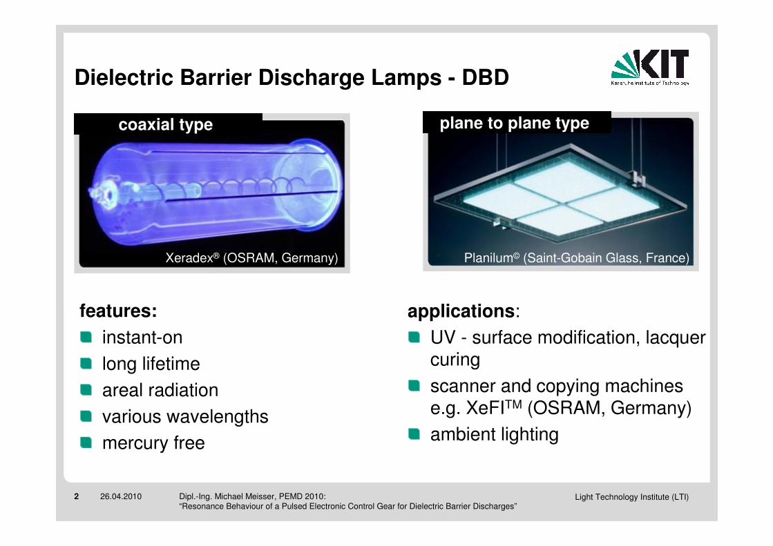
Dielectric Barrier Discharge Lamps - DBD
coaxial type plane to plane type
applications:
UV - surface modification, lacquer curing
scanner and copying machines e.g. XeFITM (OSRAM, Germany)
ambient lighting
features:
instant-on
long lifetime
areal radiation
various wavelengths
mercury free
Planilum© (Saint-Gobain Glass, France)Xeradex® (OSRAM, Germany)
Light Technology Institute (LTI)3 26.04.2010 Dipl.-Ing. Michael Meisser, PEMD 2010: “Resonance Behaviour of a Pulsed Electronic Control Gear for Dielectric Barrier Discharges”
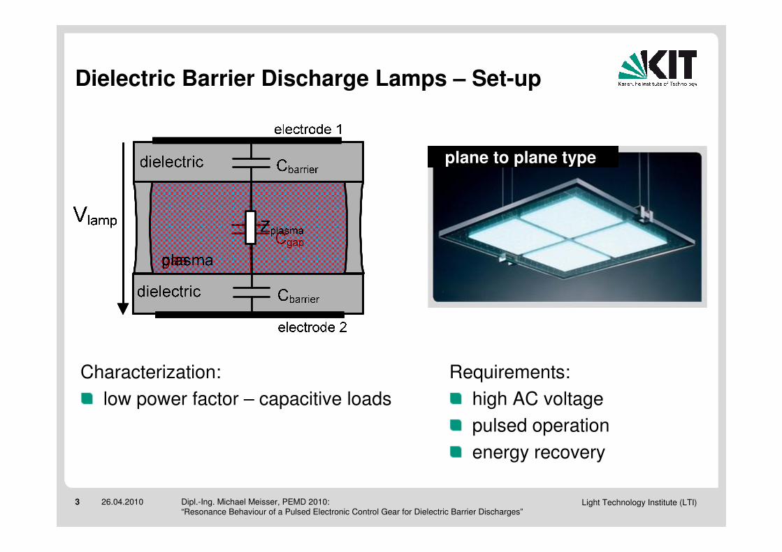
Dielectric Barrier Discharge Lamps – Set-up
plane to plane type
Characterization:
low power factor – capacitive loads
Requirements:
high AC voltage
pulsed operation
energy recovery
Light Technology Institute (LTI)4 26.04.2010 Dipl.-Ing. Michael Meisser, PEMD 2010: “Resonance Behaviour of a Pulsed Electronic Control Gear for Dielectric Barrier Discharges”
0 5 10 15 20 25 30-2000
-1500
-1000
-500
0
500
1000
1500
2000
vlamp
vla
mp [
V]
time [µs]
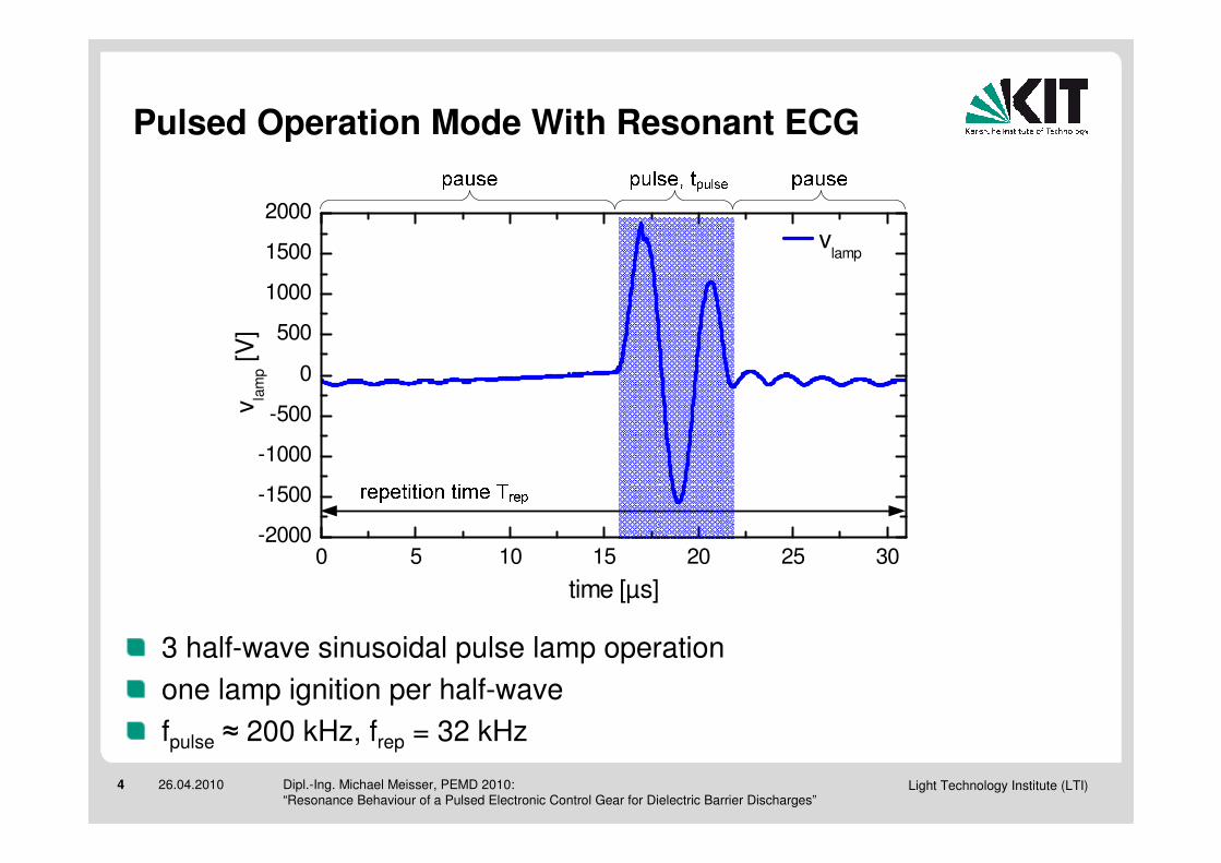
Pulsed Operation Mode With Resonant ECG
3 half-wave sinusoidal pulse lamp operation
one lamp ignition per half-wave
fpulse ≈ 200 kHz, frep = 32 kHz
Light Technology Institute (LTI)5 26.04.2010 Dipl.-Ing. Michael Meisser, PEMD 2010: “Resonance Behaviour of a Pulsed Electronic Control Gear for Dielectric Barrier Discharges”
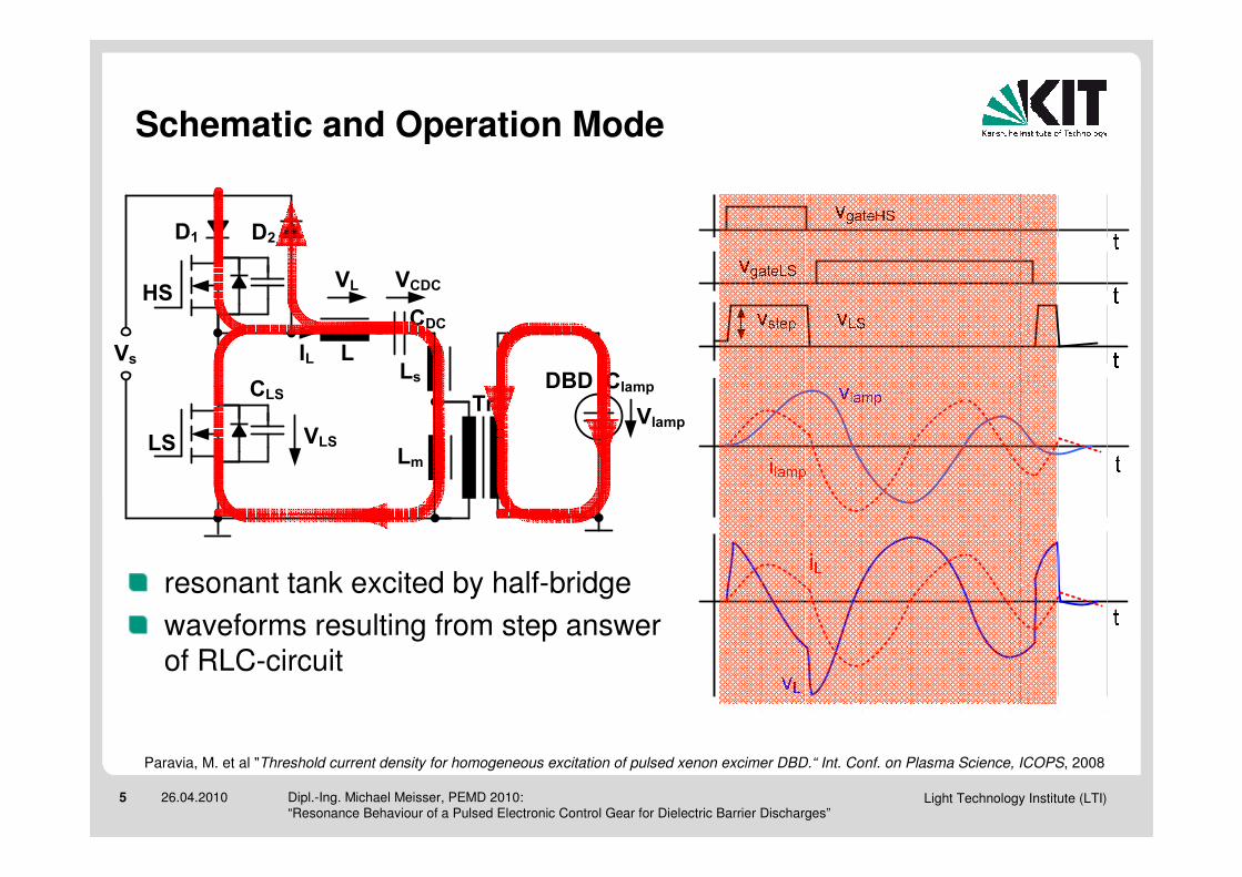
Schematic and Operation Mode
HS
LS
L
Tr
CDC
Vs
D1 D2
ClampDBD
Lm
LsIL
VlampVLS
VL VCDC
CLS
resonant tank excited by half-bridge
waveforms resulting from step answer of RLC-circuit
Paravia, M. et al "Threshold current density for homogeneous excitation of pulsed xenon excimer DBD.“ Int. Conf. on Plasma Science, ICOPS, 2008

Light Technology Institute (LTI)6 26.04.2010 Dipl.-Ing. Michael Meisser, PEMD 2010: “Resonance Behaviour of a Pulsed Electronic Control Gear for Dielectric Barrier Discharges”
10 20 30 40 50 60 70 80 90-2000
-1000
0
1000
2000
time [µs]
vla
mp [
V]
10 20 30 40 50 60 70 80 90-20
-10
0
10
20
i la
mp [
A]
Problem of Parasitic Parallel Resonance
magnetic runaway of magnetic components
peak currents may destruct half-bridge
excessive v-t products
Light Technology Institute (LTI)7 26.04.2010 Dipl.-Ing. Michael Meisser, PEMD 2010: “Resonance Behaviour of a Pulsed Electronic Control Gear for Dielectric Barrier Discharges”
HS
LS
L
Tr
CDC
Vs
D1 D2
ClampDBD
Lm
Ls
CLS
HS
LS
L
Tr
CDC
Vs
D1 D2
ClampDBD
Lm
Ls
CLS
HS
LS
L
Tr
CDC
Vs
D1 D2
ClampDBD
Lm
Ls
CLS
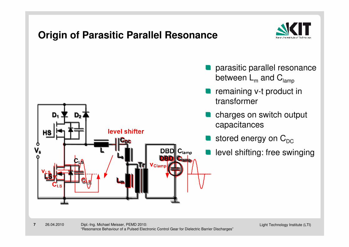
Origin of Parasitic Parallel Resonance
remaining v-t product in transformer
charges on switch output capacitances
stored energy on CDC
level shifting: free swinging
parasitic parallel resonance between Lm and Clamp
HS
LS
L
Tr
CDC
Vs
D1 D2
ClampDBD
Lm
Ls
CLS
HS
LS
L
Tr
CDC
Vs
D1 D2
ClampDBD
Lm
LsCLS
Light Technology Institute (LTI)8 26.04.2010 Dipl.-Ing. Michael Meisser, PEMD 2010: “Resonance Behaviour of a Pulsed Electronic Control Gear for Dielectric Barrier Discharges”
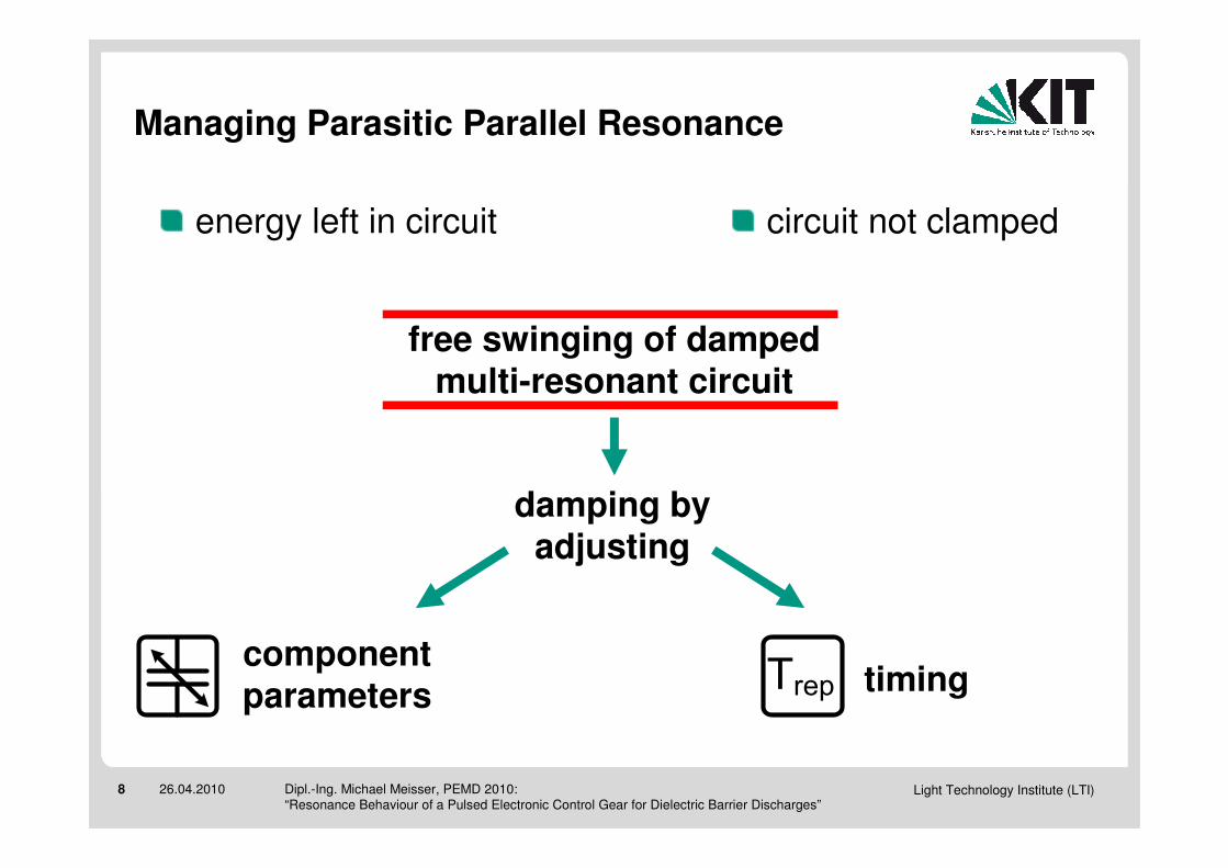
Managing Parasitic Parallel Resonance
damping by adjusting
componentparameters timing
energy left in circuit circuit not clamped
free swinging of damped multi-resonant circuit
Trep

Light Technology Institute (LTI)9 26.04.2010 Dipl.-Ing. Michael Meisser, PEMD 2010: “Resonance Behaviour of a Pulsed Electronic Control Gear for Dielectric Barrier Discharges”
Damping by Parameter Variation
reduction of quality factor of parasitic parallel resonance
HS
LS
L
Tr
CDC
Vs
D1 D2
ClampDBD
Lm
Ls
CLS
HS
LS
L
Tr
CDC
Vs
D1 D2
ClampDBD
Lm
Ls
CLS
HS
LS
L
Tr
CDC
Vs
D1 D2
ClampDBD
Lm
Ls
CLS
lamp capacitance fixed by application
transformer optimized and fixed by v-t rating
transistors fixed by max currents
DC-blocking capacitor
low damping possible to cost of reduced ignition support
HS
LS
L
Tr
CDC
Vs
D1 D2
ClampDBD
Lm
Ls
CLS
HS
LS
L
Tr
CDC
Vs
D1 D2
ClampDBD
Lm
LsCLS
Light Technology Institute (LTI)10 26.04.2010 Dipl.-Ing. Michael Meisser, PEMD 2010: “Resonance Behaviour of a Pulsed Electronic Control Gear for Dielectric Barrier Discharges”
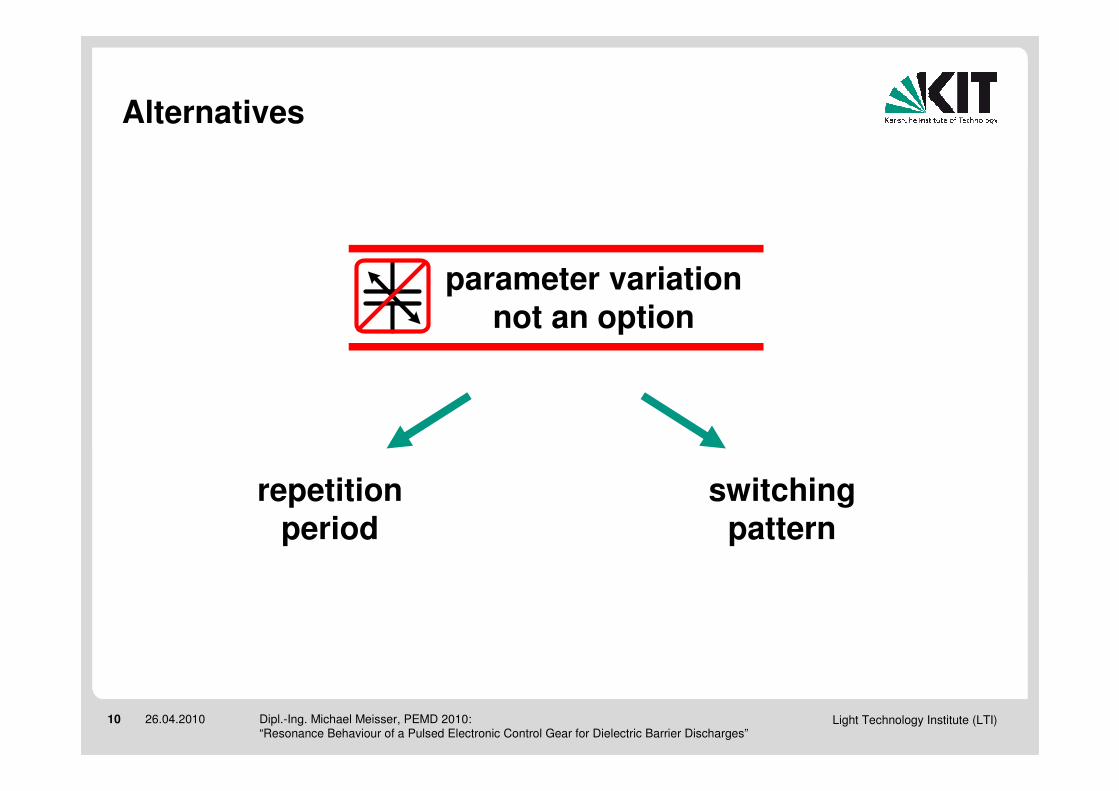
Alternatives
switching pattern
repetition period
parameter variation not an option

Light Technology Institute (LTI)11 26.04.2010 Dipl.-Ing. Michael Meisser, PEMD 2010: “Resonance Behaviour of a Pulsed Electronic Control Gear for Dielectric Barrier Discharges”
0 1 2 3 4 5 6 7
x 10-5
-2
-1.5
-1
-0.5
0
0.5
1
1.5
2x 10
-3
t [ s ]
tra
nsfo
rme
r se
co
nd
ary
v-t
pro
du
ct [V
s]
25µs
44µs
60µs
Adjusting Repetition Period
optimize preconditions for next pulse
pulse
pp
rep tf
nT ++++
⋅⋅⋅⋅
++++≈≈≈≈
2
21
therefore meet:
reduced v-t product swing
reduced amplitude of resonance
n = 1
excessive v-t products!
n = 0
pulse start in minimum of volt-second swing – initial VLS minimal
Light Technology Institute (LTI)12 26.04.2010 Dipl.-Ing. Michael Meisser, PEMD 2010: “Resonance Behaviour of a Pulsed Electronic Control Gear for Dielectric Barrier Discharges”
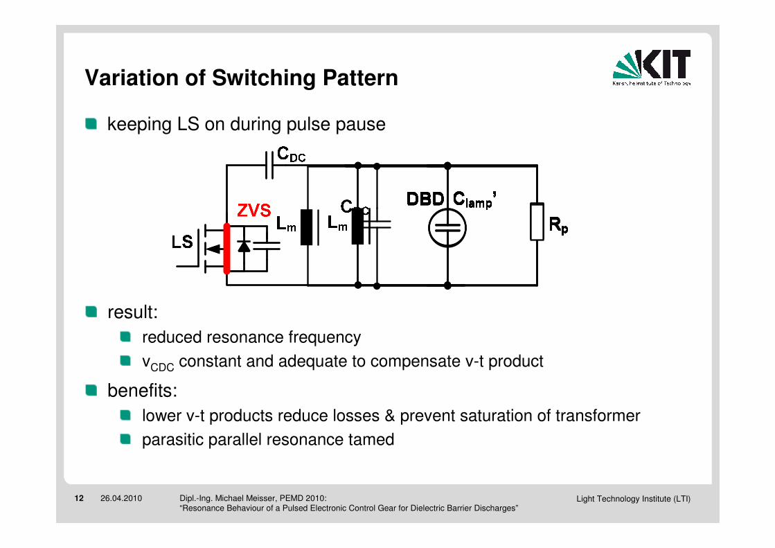
Variation of Switching Pattern
keeping LS on during pulse pause
result:
reduced resonance frequency
vCDC constant and adequate to compensate v-t product
benefits:
lower v-t products reduce losses & prevent saturation of transformer
parasitic parallel resonance tamed

Light Technology Institute (LTI)13 26.04.2010 Dipl.-Ing. Michael Meisser, PEMD 2010: “Resonance Behaviour of a Pulsed Electronic Control Gear for Dielectric Barrier Discharges”
Additional Benefit: ZVS for HS On-Transition
x 10
3x 10
-3
0 0.2 0.4 0.6 0.8 1
x 10-4
0
100
200
300
400
VL
S[V
]
utilization of EL to charge CHS
VLSgate
time [s]
►efficiency increase from 80 % to 82 %
►ZVS turn-on of HS
keeping LS on during pulse pause but opened prior to next pulse
short closing directly before pulse stores energy in L
►tamed resonance

Light Technology Institute (LTI)14 26.04.2010 Dipl.-Ing. Michael Meisser, PEMD 2010: “Resonance Behaviour of a Pulsed Electronic Control Gear for Dielectric Barrier Discharges”
Comparision of switching patterns
0 0.2 0.4 0.6 0.8 1
x 10-4
-2000
-1000
0
1000
2000
0 0.2 0.4 0.6 0.8 1
x 10-4
-1
0
1
2
3x 10
-3
time [ s ] time [ s ] time [ s ] time [ s ]
0 0.2 0.4 0.6 0.8 1
x 10-4
0
100
200
300
400
V V V VLL LL
SS SS [
V ]
[ V
] [
V ]
[ V
]
0 0.2 0.4 0.6 0.8 1
x 10-4
0
100
200
300
400
0 0.2 0.4 0.6 0.8 1
x 10-4
-2000
-1000
0
1000
2000
V V V Vll ll aa aa
mm mmpp pp [
V ]
[ V
] [
V ]
[ V
]
0 0.2 0.4 0.6 0.8 1
x 10-4
-2
-1
0
1
2x 10
-3
time [ s ] time [ s ] time [ s ] time [ s ]
vt-
pro
du
ct
[ V
s ]
vt-
pro
du
ct
[ V
s ]
vt-
pro
du
ct
[ V
s ]
vt-
pro
du
ct
[ V
s ]
transformer v-t product
low-switch voltage VLS
lamp voltage Vlamp
standard switching pattern enhanced switching pattern

Light Technology Institute (LTI)15 26.04.2010 Dipl.-Ing. Michael Meisser, PEMD 2010: “Resonance Behaviour of a Pulsed Electronic Control Gear for Dielectric Barrier Discharges”
To Conclude
serious problem of parasitic parallel resonance
10 20 30 40 50 60 70 80 90-2000
-1000
0
1000
2000
time [µs]
vla
mp
[V
]
10 20 30 40 50 60 70 80 90-20
-10
0
10
20
i la
mp
[A
]
advanced switching scheme tames negative effects and brings additional benefit
x 10
0 0.2 0.4 0.6 0.8 1
0
100
200
300
400
VL
S[V
]
time [s]
►increased reliability & efficiency + 2 %
0 1 2 3 4 5 6 7 8 9
x 10-5
-2
-1.5
-1
-0.5
0
0.5
1
1.5
2x 10
-3
t [ s ]
voltage-tim
e p
roduct[ V
s ]
25µs
44µs
51µs
60µs
81µsadaption of repetition period Trep shrinks resonant amplitude
resonant ECG drives DBD lamp
Light Technology Institute (LTI)16 26.04.2010 Dipl.-Ing. Michael Meisser, PEMD 2010: “Resonance Behaviour of a Pulsed Electronic Control Gear for Dielectric Barrier Discharges”
Question and Answer Part
Question and Answer Part
Question and Answer Part
Question and Answer Part