Embed Size (px)
Citation preview
ARL-TN-0759•MAY 2016
US Army Research Laboratory
Resolving the Orientation of Cylinders andCuboids fromProjected AreaMeasurementsby Richard Saucier
Approved for public release; distribution is unlimited.
NOTICES
Disclaimers
The findings in this report are not to be construed as an official Department of theArmy position unless so designated by other authorized documents.
Citation of manufacturer’s or trade names does not constitute an official endorsementor approval of the use thereof.
Destroy this report when it is no longer needed. Do not return it to the originator.
ARL-TN-0759•MAY 2016
US Army Research Laboratory
Resolving the Orientation of Cylinders andCuboids fromProjected AreaMeasurementsby Richard SaucierSurvivability/Lethality Analysis Directorate, ARL
Approved for public release; distribution is unlimited.
REPORT DOCUMENTATION PAGE Form Approved
OMB No. 0704‐0188
Public reporting burden for this collection of information is estimated to average 1 hour per response, including the time for reviewing instructions, searching existing data sources, gathering and maintaining the data needed, and completing and reviewing the collection information. Send comments regarding this burden estimate or any other aspect of this collection of information, including suggestions for reducing the burden, to Department of Defense, Washington Headquarters Services, Directorate for Information Operations and Reports (0704‐0188), 1215 Jefferson Davis Highway, Suite 1204, Arlington, VA 22202‐4302. Respondents should be aware that notwithstanding any other provision of law, no person shall be subject to any penalty for failing to comply with a collection of information if it does not display a currently valid OMB control number.
PLEASE DO NOT RETURN YOUR FORM TO THE ABOVE ADDRESS.
1. REPORT DATE (DD‐MM‐YYYY)
2. REPORT TYPE
3. DATES COVERED (From ‐ To)
4. TITLE AND SUBTITLE
5a. CONTRACT NUMBER
5b. GRANT NUMBER
5c. PROGRAM ELEMENT NUMBER
6. AUTHOR(S)
5d. PROJECT NUMBER
5e. TASK NUMBER
5f. WORK UNIT NUMBER
7. PERFORMING ORGANIZATION NAME(S) AND ADDRESS(ES)
8. PERFORMING ORGANIZATION REPORT NUMBER
9. SPONSORING/MONITORING AGENCY NAME(S) AND ADDRESS(ES)
10. SPONSOR/MONITOR’S ACRONYM(S)
11. SPONSOR/MONITOR'S REPORT NUMBER(S)
12. DISTRIBUTION/AVAILABILITY STATEMENT
13. SUPPLEMENTARY NOTES
14. ABSTRACT
15. SUBJECT TERMS
16. SECURITY CLASSIFICATION OF: 17. LIMITATION OF ABSTRACT
18. NUMBER OF PAGES
19a. NAME OF RESPONSIBLE PERSON
a. REPORT
b. ABSTRACT
c. THIS PAGE
19b. TELEPHONE NUMBER (Include area code)
Standard Form 298 (Rev. 8/98)
Prescribed by ANSI Std. Z39.18
May 2016 Final
Resolving the Orientation of Cylinders and Cuboids from Projected AreaMeasurements
Richard Saucier
ARL-TN-0759
Approved for public release; distribution is unlimited.
November 2015–January 2016
AH80
US Army Research LaboratoryATTN: RDRL-SLB-SAberdeen Proving Ground, MD 21005-5068
The FATEPEN model predicts the penetration of a mass striking a target plate for a variety of shapes, including cylinders andcuboids—among others. Crucial to the use of the model is a good estimate of not only the mass and velocity but also the impactorientation in terms of pitch, yaw, and roll. Yaw cards and orthogonal X-rays can provide estimates of the impact projected area,but the model makes use of the impact angle, which is defined to be the minimum angle that a face makes with the target plate.This report addresses this issue by calculating the pitch-yaw-roll rotation sequence that will bring about the orientation at impactfrom orthogonal projected area measurements. It is shown that the impact angle is uniquely determined in the case of cylinders,but that is not the case for cuboids. Furthermore, for cuboids multiple impact angles for the same projected area measurements canlead to significantly different FATEPEN predictions. This leads to the conclusion that cylinders and not cuboids should be used forFATEPEN validation.
FATEPEN, RCC, RPP, fragment impact, fragment orientation, projected area, orthogonal X-rays, pitch-yaw-roll
44
Richard Saucier
410-278-6721Unclassified Unclassified Unclassified UU
ii
Approved for public release; distribution is unlimited.
Contents
List of Figures v
List of Tables vi
List of Listings vii
Acknowledgments viii
1. Summary 1
2. Introduction 1
3. Methods, Assumptions, and Procedures 23.1 Orientation of a Cylinder 3
3.1.1 Projected Areas from Cylinder Orientation 33.1.2 Cylinder Orientation from Projected Areas 4
3.2 Orientation of a Cuboid 63.2.1 Projected Areas from Cuboid Orientation 73.2.2 Cuboid Orientation from Projected Areas 9
4. Results and Discussion 144.1 Cylinder Orientation Sample Case 144.2 Cuboid Orientation Sample Case 16
4.2.1 Impact Angle and Effective Yaw Angle 17
5. Conclusions 19
6. References 21
Appendix A. Formula for an Euler Sequence of Rotations 23
Appendix B. Yaw Angle of a Cylinder as a Function of Shape Factor 29
List of Symbols, Abbreviations, and Acronyms 33
iii

Approved for public release; distribution is unlimited.
Distribution List 34
iv

Approved for public release; distribution is unlimited.
List of FiguresFig. 1 Description of pitch, yaw, and roll. ................................................2
Fig. 2 An oriented cylinder with projected area on orthogonal planes ........... 16
Fig. 3 An oriented cuboid with projected area on orthogonal planes ............. 16
v

Approved for public release; distribution is unlimited.
List of TablesTable 1 Pitch, yaw, and roll rotations of unit vectors ..................................3
Table 2 FATEPEN predictions for a 725-gr steel cuboid with a striking velocity of1500 f/s impacting a 0.25-inch mild steel plate using version 3.3.10.3. Ineach case, the projected areas on the orthogonal planes are the same. Note,in particular, the sensitivity of the residual velocity, vr. ................... 17
Table 3 FATEPEN predictions for a 725-gr steel cuboid with a striking velocity of1500 f/s impacting a 0.25-inch mild steel plate using version 3.3.18.0. Ineach case, the projected areas on the orthogonal planes are the same. . 19
vi

Approved for public release; distribution is unlimited.
List of ListingsListing 1 orient.cpp . . . . . . . . . . . . . . . . . . . . . . . . . . . . . . . . . . . . . . . . . . . . . . . . . . . . . . . . . . . . 12
Listing 2 rcc.cpp. . . . . . . . . . . . . . . . . . . . . . . . . . . . . . . . . . . . . . . . . . . . . . . . . . . . . . . . . . . . . . . . 14
Listing A-1 reverse.cpp . . . . . . . . . . . . . . . . . . . . . . . . . . . . . . . . . . . . . . . . . . . . . . . . . . . . . . . . . . . 27
Listing B-1 cyl.cpp. . . . . . . . . . . . . . . . . . . . . . . . . . . . . . . . . . . . . . . . . . . . . . . . . . . . . . . . . . . . . . . . 31
vii

Approved for public release; distribution is unlimited.
AcknowledgmentsI would like to thank Timothy Mallory for his interest in this problem, suggestionsthat improved this report, and the numerous stand-alone FATEPEN runs he conductedto check the results. I would also like to thank John Auten for catching some errorsand his technical review of this document. Of course, I accept full responsibility forany errors that may remain.
viii
Approved for public release; distribution is unlimited.
1. SummaryThe FATEPEN model predicts the penetration of a mass striking a target plate fora variety of shapes, including cylinders and cuboids—among others. Crucial tothe use of the model is a good estimate of not only the mass and velocity but alsothe impact orientation in terms of pitch, yaw, and roll. Yaw cards and orthogonalX-rays can provide estimates of the impact projected area, but the model makes useof the impact angle, which is defined to be the minimum angle that a penetratorface makes with the target plate. This report addresses this issue by calculating thepitch-yaw-roll rotation sequence that will bring about the orientation at impact fromorthogonal projected area measurements. It is shown that the impact angle is uniquelydetermined in the case of cylinders, but that is not the case for cuboids. Furthermore,for cuboids multiple impact angles for the same projected area measurements canlead to significantly different FATEPEN predictions. This leads to the conclusionthat cylinders and not cuboids should be used for FATEPEN validation.
2. IntroductionThe FATEPEN1 model is a Fortran code for simulating penetration of fragments,long rods, and projectiles into target plates and predicting penetration, perforation,residual mass, and residual velocity. It provides the following shapes: sphere, rightcircular cylinder (RCC), round-nose cylinder, sharp-nose cylinder, tapered/truncatedcylinder, and rectangular parallelepiped (RPP). This report is limited to RCCs, whichwe will simply call cylinders, and RPPs, which we will call cuboids. Unlike theTHOR2 model, which only requires an impact presented area, the FATEPEN modelrequires a specific shape and orientation.
The impact presented area, or projected area, is a key parameter that affects thepenetration process since the penetration depth scales with the mass per unit pre-sented area for a given striking velocity. But the FATEPEN model goes beyondthe presented area and also requires the angle that each flat face of the strikingmass makes with the target plate. This means that we need to account for both thepresented area and the orientation of the fragment to use FATEPEN properly.
1
Approved for public release; distribution is unlimited.
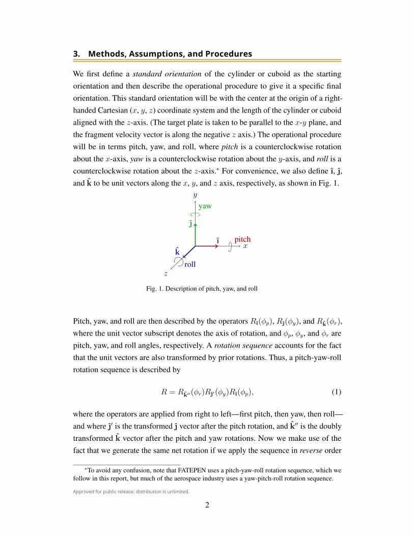
3. Methods, Assumptions, and ProceduresWe first define a standard orientation of the cylinder or cuboid as the startingorientation and then describe the operational procedure to give it a specific finalorientation. This standard orientation will be with the center at the origin of a right-handed Cartesian (x, y, z) coordinate system and the length of the cylinder or cuboidaligned with the z-axis. (The target plate is taken to be parallel to the x-y plane, andthe fragment velocity vector is along the negative z axis.) The operational procedurewill be in terms pitch, yaw, and roll, where pitch is a counterclockwise rotationabout the x-axis, yaw is a counterclockwise rotation about the y-axis, and roll is acounterclockwise rotation about the z-axis.∗ For convenience, we also define ı, ,and k to be unit vectors along the x, y, and z axis, respectively, as shown in Fig. 1.
x
y
z
ı
k
yaw
pitch
roll
Fig. 1. Description of pitch, yaw, and roll
Pitch, yaw, and roll are then described by the operators Rı(φp), R(φy), and Rk(φr),where the unit vector subscript denotes the axis of rotation, and φp, φy, and φr arepitch, yaw, and roll angles, respectively. A rotation sequence accounts for the factthat the unit vectors are also transformed by prior rotations. Thus, a pitch-yaw-rollrotation sequence is described by
R = Rk′′(φr)R′(φy)Rı(φp), (1)
where the operators are applied from right to left—first pitch, then yaw, then roll—and where ′ is the transformed vector after the pitch rotation, and k′′ is the doublytransformed k vector after the pitch and yaw rotations. Now we make use of thefact that we generate the same net rotation if we apply the sequence in reverse order
∗To avoid any confusion, note that FATEPEN uses a pitch-yaw-roll rotation sequence, which wefollow in this report, but much of the aerospace industry uses a yaw-pitch-roll rotation sequence.
2
Approved for public release; distribution is unlimited.
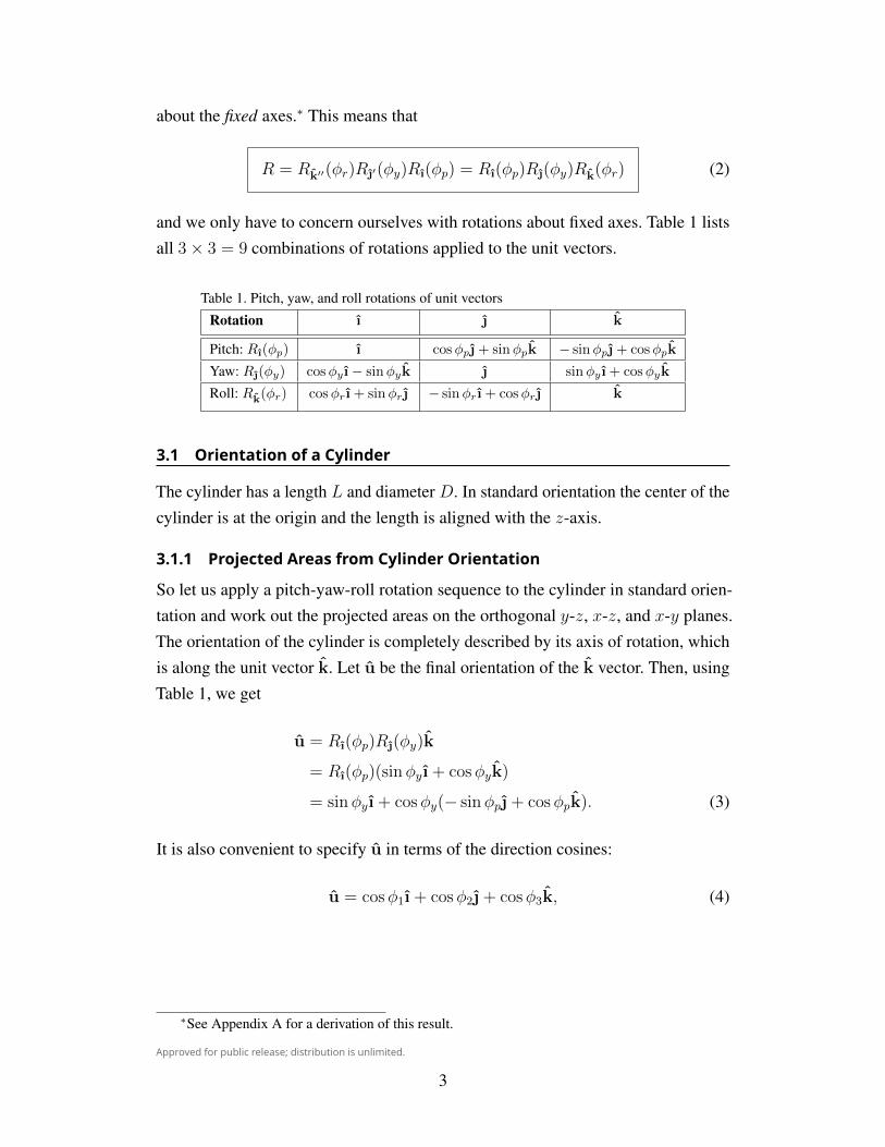
about the fixed axes.∗ This means that
R = Rk′′(φr)R′(φy)Rı(φp) = Rı(φp)R(φy)Rk(φr) (2)
and we only have to concern ourselves with rotations about fixed axes. Table 1 listsall 3× 3 = 9 combinations of rotations applied to the unit vectors.
Table 1. Pitch, yaw, and roll rotations of unit vectors
Rotation ı k
Pitch: Rı(φp) ı cosφp + sinφpk − sinφp + cosφpk
Yaw: R(φy) cosφy ı− sinφyk sinφy ı + cosφyk
Roll: Rk(φr) cosφrı + sinφr − sinφrı + cosφr k
3.1 Orientation of a CylinderThe cylinder has a length L and diameter D. In standard orientation the center of thecylinder is at the origin and the length is aligned with the z-axis.
3.1.1 Projected Areas from Cylinder OrientationSo let us apply a pitch-yaw-roll rotation sequence to the cylinder in standard orien-tation and work out the projected areas on the orthogonal y-z, x-z, and x-y planes.The orientation of the cylinder is completely described by its axis of rotation, whichis along the unit vector k. Let u be the final orientation of the k vector. Then, usingTable 1, we get
u = Rı(φp)R(φy)k
= Rı(φp)(sinφyı + cosφyk)
= sinφyı + cosφy(− sinφp + cosφpk). (3)
It is also convenient to specify u in terms of the direction cosines:
u = cosφ1ı + cosφ2 + cosφ3k, (4)
∗See Appendix A for a derivation of this result.
3
Approved for public release; distribution is unlimited.
where cosφ1 = u · ı, cosφ2 = u · , and cosφ3 = u · k. Comparing Eqs. 3 and 4gives the correspondence
φ1 = cos−1(sinφy),
φ2 = cos−1(− sinφp cosφy), (5)
φ3 = cos−1(cosφp cosφy).
Let L be the length of the cylinder and D be its diameter. Then the projected areasonto the orthogonal planes are
Ayz = LD| cos(π2− φ1
)|+ π
4D2| cosφ1| = LD| sinφ1|+
π
4D2| cosφ1|
Axz = LD| cos(π2− φ2
)|+ π
4D2| cosφ2| = LD| sinφ2|+
π
4D2| cosφ2| . (6)
Axy = LD| cos(π2− φ3
)|+ π
4D2| cosφ3| = LD| sinφ3|+
π
4D2| cosφ3|
Therefore, given the pitch and yaw of the cylinder, Eqs. 5 and 6 give us the projectedareas.
3.1.2 Cylinder Orientation from Projected AreasNext, we work out the inverse problem of determining the pitch and yaw from themeasured projected areas. Thus, given the length L, diameter D, and the projectedareas of an RCC onto the orthogonal planes, we want to solve for the orientation ofthe RCC. More specifically, we seek the FATEPEN pitch and yaw rotation sequencethat will bring about this orientation.∗ It is convenient in what follows to specify thefinal orientation in terms of the polar angle, θ, measured from the z-axis and φ, theazimuthal angle measured from the x-axis in the x-y plane:
u = sin θ cos φı + sin θ sin φ + cos θk. (7)
There is no loss of generality if we restrict u to lie in the first octant of the unitsphere, so that
0 ≤ θ ≤ π/2 and 0 ≤ φ ≤ π/2. (8)
∗Ordinarily we would need pitch, yaw, and roll to completely specify orientation, but placing theaxis of the RCC along the z (roll) axis eliminates the need to consider roll.
4
Approved for public release; distribution is unlimited.
Comparing Eqs. 4 and 7 gives
θ = φ3 and φ = tan−1(cosφ2
cosφ1
). (9)
All the formulas in Eq. 6 are of the form
a sinα + b cosα = Ap, (10)
with α = φ1, φ2, or φ3, a = LD, b = πD2/4, and Ap the projected area, Ayz, Axz,orAxy. We can solve this for the angle α by first introducing another angle β, definedby
β ≡ tan−1(b/a), (11)
which gives a =√a2 + b2 cos β and b =
√a2 + b2 sin β, and then Eq. 10 becomes
√a2 + b2 cos β sinα +
√a2 + b2 sin β cosα =
√a2 + b2 sin(α + β) = Ap. (12)
Now it is easy to show that√a2 + b2 = Amax, the maximum presented area of the
RCC, so that 0 ≤ Ap/√a2 + b2 ≤ 1, and therefore
sin(α + β) =Ap√a2 + b2
. (13)
Two possible solutions to this equation are
α = sin−1(
Ap√a2 + b2
)− tan−1
(b
a
)or
α = π − tan−1(b
a
)− sin−1
(Ap√a2 + b2
). (14)
In practice we try both, so this gives 23 = 8 possible combinations for φ1, φ2, andφ3. But by imposing the constraint that
cos2 φ1 + cos2 φ2 + cos2 φ3 = 1, (15)
we will find that only one combination will work. Once φ1, φ2, and φ3 have thusbeen found, we return to Eq. 9 to get θ and φ.
5
Approved for public release; distribution is unlimited.
Next we need a rotation that will align k with u. It is easy to check that Re(θ), where
e =k× u
|k× u|= − sin φı + cos φ, (16)
is this rotation. That is, Re(θ)k = u. The quaternion representation of this rotationis
qe(θ) = cos(θ/2) + e sin(θ/2) = cos(θ/2) + (− sin φı + cos φ) sin(θ/2). (17)
Finally, this quaternion can be factored into a pitch-yaw-roll rotation sequence.3 Theprescription is as follows:
1. Set p0 = cos(θ/2), p1 = − sinφ sin(θ/2), p2 = cosφ sin(θ/2), p3 = 0.
2. Set A = p1p2 − p0p3, B = p21 − p23, D = p20 − p22.
3. Then φr = tan−1[−2A/(B +D)].
4. Set c0 = cos(φr/2) and c3 = sin(φr/2).
5. Set q0 = p0c0 + p3c3, q1 = p1c0 − p2c3, q2 = p2c0 + p1c3, q3 = p3c0 − p0c3.
6. Then φp = 2 tan−1(q1/q0) and φy = 2 tan−1(q2/q0).
Thus, we accomplish what we set out to do: obtain the pitch and yaw rotationsequence that will give the desired projected areas. For a cylinder there are actually4 orientations that give the same projected areas, which are (φp, φy), (φp,−φy),(−φp, φy), and (−φp,−φy).
3.2 Orientation of a CuboidThe cuboid, or RPP, has a length L, width W , and thickness T , where L ≥ W ≥ T ,and is initially oriented so that the length is along the z-axis, the width is along thex-axis and the thickness is along the y-axis. Thus, the initial areas along each of theaxes are Ax = LT , Ay = LW , and Az = WT . We take ı to be a unit vector alongthe x-axis, to be a unit vector along the y-axis, and k to be a unit vector along thez-axis. Let
u = xı + y + zk with x2 + y2 + z2 = 1 (18)
6
Approved for public release; distribution is unlimited.
be a unit vector on the unit sphere. Then the projected area of the cuboid orthogonalto u is
Ap(x, y, z) = (Axı + Ay + Azk) · u = Axx+ Ayy + Azz. (19)
As we vary the direction of u, the rate of change of the projected area is given by
DuAp =∇Ap(x, y, z) · u
= ||∇Ap(x, y, z)|| ||u|| cos θ
= ||∇Ap(x, y, z)|| cos θ, (20)
where θ is the angle between the gradient and the unit vector. From this expression,it is clear that the area is maximized when cos θ is a maximum, which occurs whenθ = 0. The gradient along this direction is
∇Ap(x, y, z) =∂Ap∂x
ı +∂Ap∂y
+∂Ap∂z
k = Axı + Ay + Azk, (21)
and therefore the magnitude of the maximum projected area is
Amax = ||∇Ap(x, y, z)|| =√A2x + A2
y + A2z , (22)
and the view direction for this maximum is given by the unit vector
umax =Axı + Ay + Azk
Amax
. (23)
By construction, the minimum projected area is initially oriented along the z-axis,Amin = Az, and is realized along the unit vector umin = k.
3.2.1 Projected Areas from Cuboid OrientationNow let us work out the projected areas from a given pitch-yaw-roll rotation se-quence, R. Again, making use of Eq. 2 and applying the rotations from Table 1successively gives
R(φy)Rk(φr)Axı = Ax cosφr(cosφyı− sinφyk) + Ax sinφr,
R(φy)Rk(φr)Ay = −Ay sinφr(cosφyı− sinφyk) + Ay cosφr, (24)
R(φy)Rk(φr)Azk = Az(sinφyı + cosφyk).
7
Approved for public release; distribution is unlimited.
Collecting terms we get
R(φy)Rk(φr)Axı = Ax cosφr cosφyı + Ax sinφr− Ax cosφr sinφyk,
R(φy)Rk(φr)Ay = −Ay sinφr cosφyı + Ay cosφr + Ay sinφr sinφyk, (25)
R(φy)Rk(φr)Azk = Az sinφyı + Az cosφyk.
Finally, applying pitch, we get
RAxı =+ Ax cosφr cosφyı
+ Ax sinφr(cosφp + sinφpk)
− Ax cosφr sinφy(− sinφp + cosφpk),
RAy =− Ay sinφr cosφyı (26)
+ Ay cosφr(cosφp + sinφpk)
+ Ay sinφr sinφy(− sinφp + cosφpk),
RAzk =+ Az sinφyı
+ Az cosφy(− sinφp + cosφpk).
and collecting terms,
RAxı =+ Ax cosφr cosφyı
+ Ax(sinφr cosφp + cosφr sinφy sinφp)
+ Ax(sinφr sinφp − cosφr sinφy cosφp)k, (27)
RAy =− Ay sinφr cosφyı
+ Ay(cosφr cosφp − sinφr sinφy sinφp)
+ Ay(cosφr sinφp + sinφr sinφy cosφp)k, (28)
RAzk =+ Az sinφyı− Az cosφy sinφp + Az cosφy cosφpk. (29)
Now let Axy be the projection on the x-y plane, Axz be the projection on the x-zplane, and Ayz be the projection on the y-z plane. Then we have
Axy = [R(Axı + Ay + Azk)] · k, (30)
Axz = [R(Axı + Ay + Azk)] · , (31)
Ayz = [R(Axı + Ay + Azk)] · ı. (32)
8
Approved for public release; distribution is unlimited.
Three is the maximum number of sides that can project unto a plane for a cuboid, sowe can include all the contributions by using the absolute value. Thus, we get theprojected areas
Axy =Ax| sinφr sinφp − cosφr sinφy cosφp|+
Ay| cosφr sinφp + sinφr sinφy cosφp|+
Az| cosφy cosφp|, (33)
Axz =Ax| sinφr cosφp + cosφr sinφy sinφp|+
Ay| cosφr cosφp − sinφr sinφy sinφp|+
Az| cosφy sinφp|, (34)
Ayz =Ax| cosφr cosφy|+ Ay| sinφr cosφy|+ Az| sinφy|. (35)
3.2.2 Cuboid Orientation from Projected AreasNext, given measured values for Axy, Axz, and Ayz, we want to solve Eqs. 33–35for φp, φy, and φr. This is a system of 3 simultaneous nonlinear equations, whichcan be solved numerically by Newton’s method in 3 dimensions. Define
f(φp, φy, φr) ≡Ax| sinφr sinφp − cosφr sinφy cosφp|+
Ay| cosφr sinφp + sinφr sinφy cosφp|+
Az| cosφy cosφp| − Axy, (36)
g(φp, φy, φr) ≡Ax| sinφr cosφp + cosφr sinφy sinφp|+
Ay| cosφr cosφp − sinφr sinφy sinφp|+
Az| cosφy sinφp| − Axz, (37)
h(φp, φy, φr) ≡ Ax| cosφr cosφy|+ Ay| sinφr cosφy|+ Az| sinφy| − Ayz. (38)
Then the problem is to find the roots of f , g, and h. Let A be the matrix of partialderivatives
A =
fφp(φp, φy, φr) fφy(φp, φy, φr) fφr(φp, φy, φr)
gφp(φp, φy, φr) gφy(φp, φy, φr) gφr(φp, φy, φr)
hφp(φp, φy, φr) hφy(φp, φy, φr) hφr(φp, φy, φr)
(39)
9
Approved for public release; distribution is unlimited.
wherefφp(φp, φy, φr) =
∂f(φp, φy, φr)
∂φp(40)
and so on for the other partial derivatives. For this we need the derivative of theabsolute value:
d
dx|u| = d
dx
√u2 =
1
2(u2)−1/22uu′ =
uu′√u2
=uu′
|u|= sgn(u)u′, (41)
where sgn(x) is the sign function:
sgn(x) =
+1 if x > 0
0 if x = 0 .
−1 if x < 0
(42)
Then from Eqs. 36–38 we get
fφp(φp, φy, φr) = +Ax sgn(sinφr sinφp − cosφr sinφy cosφp)
(sinφr cosφp + cosφr sinφy sinφp)
+Ay sgn(cosφr sinφp + sinφr sinφy cosφp)
(cosφr cosφp − sinφr sinφy sinφp)
+Az sgn(cosφy cosφp)(− cosφy sinφp), (43)
fφy(φp, φy, φr) = +Ax sgn(sinφr sinφp − cosφr sinφy cosφp)
(− cosφr cosφy sinφp)
+Ay sgn(cosφr sinφp + sinφr sinφy cosφp)
(sinφr cosφy cosφp)
+Az sgn(cosφy cosφp)(− sinφy cosφp), (44)
fφr(φp, φy, φr) = +Ax sgn(sinφr sinφp − cosφr sinφy cosφp)
(cosφr sinφp + sinφr sinφy cosφp)
+Ay sgn(cosφr sinφp + sinφr sinφy cosφp)
(− sinφr sinφp + cosφr sinφy cosφp), (45)
10
Approved for public release; distribution is unlimited.
gφp(φp, φy, φr) = +Ax sgn(sinφr cosφp + cosφr sinφy sinφp)
(− sinφr sinφp + cosφr sinφy cosφp)
+Ay sgn(cosφr cosφp − sinφr sinφy sinφp)
(− cosφr sinφp − sinφr sinφy cosφp)
+Az sgn(cosφy sinφp)(cosφy cosφp), (46)
gφy(φp, φy, φr) = +Ax sgn(sinφr cosφp + cosφr sinφy sinφp)
(cosφr cosφy sinφp)
+Ay sgn(cosφr cosφp − sinφr sinφy sinφp)
(− sinφr cosφy sinφp)
+Az sgn(cosφy sinφp)(− sinφy sinφp), (47)
gφr(φp, φy, φr) = +Ax sgn(sinφr cosφp + cosφr sinφy sinφp)
(cosφr cosφp − sinφr sinφy sinφp)
+Ay sgn(cosφr cosφp − sinφr sinφy sinφp)
(− sinφr cosφp − cosφr sinφy sinφp), (48)
hφp(φp, φy, φr) = 0, (49)
hφy(φp, φy, φr) = +Ax sgn(cosφr cosφy)(− cosφr sinφy)+
+Ay sgn(sinφr cosφy)(− sinφr sinφy)+
+Az sgn(sinφy)(cosφy), (50)
hφr(φp, φy, φr) = +Ax sgn(cosφr cosφy)(− sinφr cosφy)
+Ay sgn(sinφr cosφy)(cosφr cosφy). (51)
Newton’s method for solving this 3-dimensional (3D) problem numerically for pitch,yaw, and roll is expressed by the matrix iteration equationδφpδφy
δφr
≡φp,n+1 − φp,nφy,n+1 − φy,nφr,n+1 − φr,n
= A−1
f(φp, φy, φr)g(φp, φy, φr)
h(φp, φy, φr)
, (52)
where the matrix A is given by Eq. 39. We pick a starting orientation and continueiterating until either the δ’s fall below a preset tolerance value ε or we exceed amaximum number of iterations—in which case we try another starting orientation.
11
Approved for public release; distribution is unlimited.
If we write this coefficient matrix (Eq. 39) as
A =
a11 a12 a13
a21 a22 a23
a31 a32 a33
, (53)
then the inverse is given by
A−1 =1
detA
a22a33 − a23a32 a13a32 − a12a33 a12a23 − a13a22a23a31 − a21a33 a11a33 − a13a31 a13a21 − a11a23a21a32 − a22a31 a12a31 − a11a32 a11a22 − a12a21
. (54)
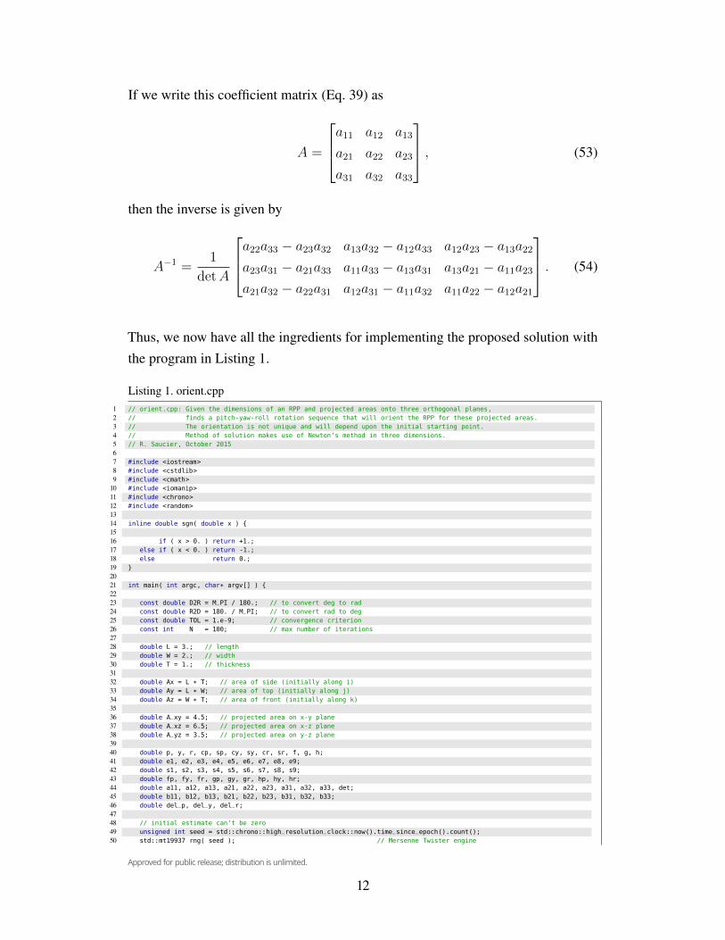
Thus, we now have all the ingredients for implementing the proposed solution withthe program in Listing 1.
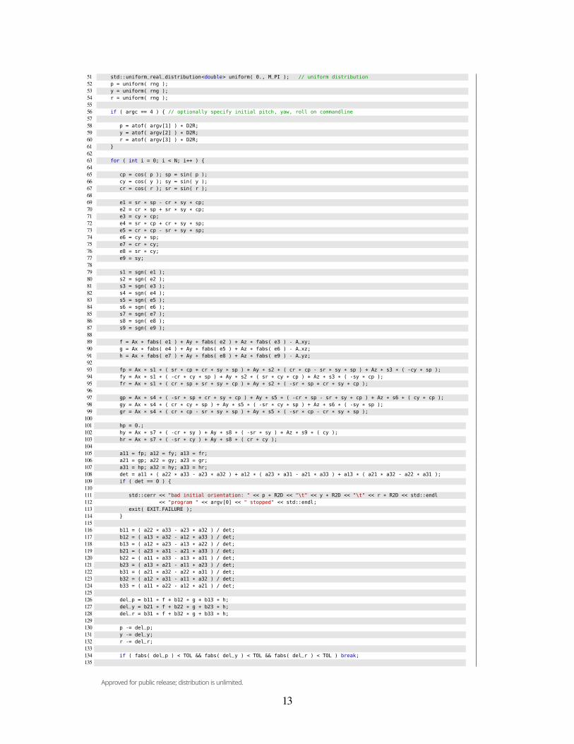
Listing 1. orient.cpp1 // orient.cpp: Given the dimensions of an RPP and projected areas onto three orthogonal planes,2 // finds a pitch-yaw-roll rotation sequence that will orient the RPP for these projected areas.3 // The orientation is not unique and will depend upon the initial starting point.4 // Method of solution makes use of Newton’s method in three dimensions.5 // R. Saucier, October 201567 #include <iostream>8 #include <cstdlib>9 #include <cmath>
10 #include <iomanip>11 #include <chrono>12 #include <random>1314 inline double sgn( double x ) {1516 if ( x > 0. ) return +1.;17 else if ( x < 0. ) return -1.;18 else return 0.;19 }2021 int main( int argc, char* argv[] ) {2223 const double D2R = M_PI / 180.; // to convert deg to rad24 const double R2D = 180. / M_PI; // to convert rad to deg25 const double TOL = 1.e-9; // convergence criterion26 const int N = 100; // max number of iterations2728 double L = 3.; // length29 double W = 2.; // width30 double T = 1.; // thickness3132 double Ax = L * T; // area of side (initially along i)33 double Ay = L * W; // area of top (initially along j)34 double Az = W * T; // area of front (initially along k)3536 double A_xy = 4.5; // projected area on x-y plane37 double A_xz = 6.5; // projected area on x-z plane38 double A_yz = 3.5; // projected area on y-z plane3940 double p, y, r, cp, sp, cy, sy, cr, sr, f, g, h;41 double e1, e2, e3, e4, e5, e6, e7, e8, e9;42 double s1, s2, s3, s4, s5, s6, s7, s8, s9;43 double fp, fy, fr, gp, gy, gr, hp, hy, hr;44 double a11, a12, a13, a21, a22, a23, a31, a32, a33, det;45 double b11, b12, b13, b21, b22, b23, b31, b32, b33;46 double del_p, del_y, del_r;4748 // initial estimate can’t be zero49 unsigned int seed = std::chrono::high_resolution_clock::now().time_since_epoch().count();50 std::mt19937 rng( seed ); // Mersenne Twister engine
12
Approved for public release; distribution is unlimited.
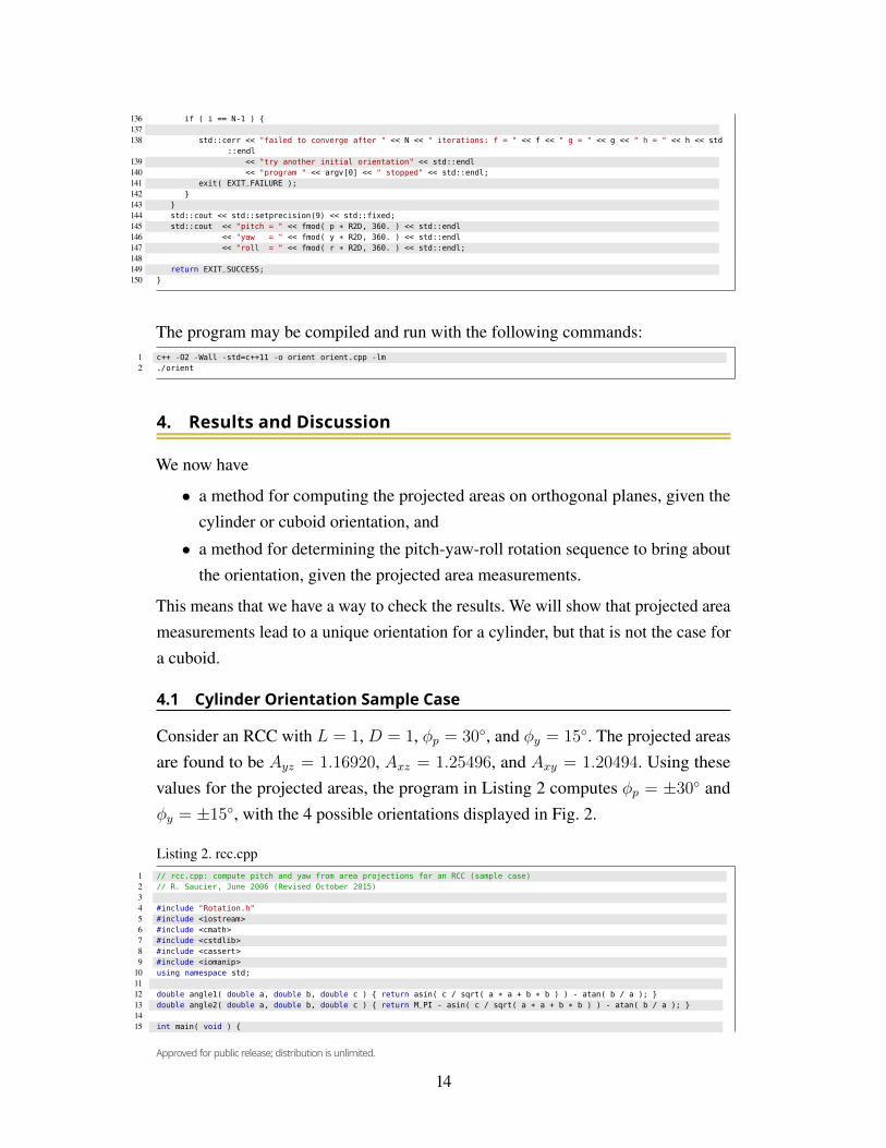
51 std::uniform_real_distribution<double> uniform( 0., M_PI ); // uniform distribution52 p = uniform( rng );53 y = uniform( rng );54 r = uniform( rng );5556 if ( argc == 4 ) { // optionally specify initial pitch, yaw, roll on commandline5758 p = atof( argv[1] ) * D2R;59 y = atof( argv[2] ) * D2R;60 r = atof( argv[3] ) * D2R;61 }6263 for ( int i = 0; i < N; i++ ) {6465 cp = cos( p ); sp = sin( p );66 cy = cos( y ); sy = sin( y );67 cr = cos( r ); sr = sin( r );6869 e1 = sr * sp - cr * sy * cp;70 e2 = cr * sp + sr * sy * cp;71 e3 = cy * cp;72 e4 = sr * cp + cr * sy * sp;73 e5 = cr * cp - sr * sy * sp;74 e6 = cy * sp;75 e7 = cr * cy;76 e8 = sr * cy;77 e9 = sy;7879 s1 = sgn( e1 );80 s2 = sgn( e2 );81 s3 = sgn( e3 );82 s4 = sgn( e4 );83 s5 = sgn( e5 );84 s6 = sgn( e6 );85 s7 = sgn( e7 );86 s8 = sgn( e8 );87 s9 = sgn( e9 );8889 f = Ax * fabs( e1 ) + Ay * fabs( e2 ) + Az * fabs( e3 ) - A_xy;90 g = Ax * fabs( e4 ) + Ay * fabs( e5 ) + Az * fabs( e6 ) - A_xz;91 h = Ax * fabs( e7 ) + Ay * fabs( e8 ) + Az * fabs( e9 ) - A_yz;9293 fp = Ax * s1 * ( sr * cp + cr * sy * sp ) + Ay * s2 * ( cr * cp - sr * sy * sp ) + Az * s3 * ( -cy * sp );94 fy = Ax * s1 * ( -cr * cy * sp ) + Ay * s2 * ( sr * cy * cp ) + Az * s3 * ( -sy * cp );95 fr = Ax * s1 * ( cr * sp + sr * sy * cp ) + Ay * s2 * ( -sr * sp + cr * sy * cp );9697 gp = Ax * s4 * ( -sr * sp + cr * sy * cp ) + Ay * s5 * ( -cr * sp - sr * sy * cp ) + Az * s6 * ( cy * cp );98 gy = Ax * s4 * ( cr * cy * sp ) + Ay * s5 * ( -sr * cy * sp ) + Az * s6 * ( -sy * sp );99 gr = Ax * s4 * ( cr * cp - sr * sy * sp ) + Ay * s5 * ( -sr * cp - cr * sy * sp );
100101 hp = 0.;102 hy = Ax * s7 * ( -cr * sy ) + Ay * s8 * ( -sr * sy ) + Az * s9 * ( cy );103 hr = Ax * s7 * ( -sr * cy ) + Ay * s8 * ( cr * cy );104105 a11 = fp; a12 = fy; a13 = fr;106 a21 = gp; a22 = gy; a23 = gr;107 a31 = hp; a32 = hy; a33 = hr;108 det = a11 * ( a22 * a33 - a23 * a32 ) + a12 * ( a23 * a31 - a21 * a33 ) + a13 * ( a21 * a32 - a22 * a31 );109 if ( det == 0 ) {110111 std::cerr << "bad initial orientation: " << p * R2D << "\t" << y * R2D << "\t" << r * R2D << std::endl112 << "program " << argv[0] << " stopped" << std::endl;113 exit( EXIT_FAILURE );114 }115116 b11 = ( a22 * a33 - a23 * a32 ) / det;117 b12 = ( a13 * a32 - a12 * a33 ) / det;118 b13 = ( a12 * a23 - a13 * a22 ) / det;119 b21 = ( a23 * a31 - a21 * a33 ) / det;120 b22 = ( a11 * a33 - a13 * a31 ) / det;121 b23 = ( a13 * a21 - a11 * a23 ) / det;122 b31 = ( a21 * a32 - a22 * a31 ) / det;123 b32 = ( a12 * a31 - a11 * a32 ) / det;124 b33 = ( a11 * a22 - a12 * a21 ) / det;125126 del_p = b11 * f + b12 * g + b13 * h;127 del_y = b21 * f + b22 * g + b23 * h;128 del_r = b31 * f + b32 * g + b33 * h;129130 p -= del_p;131 y -= del_y;132 r -= del_r;133134 if ( fabs( del_p ) < TOL && fabs( del_y ) < TOL && fabs( del_r ) < TOL ) break;135
13
Approved for public release; distribution is unlimited.
136 if ( i == N-1 ) {137138 std::cerr << "failed to converge after " << N << " iterations: f = " << f << " g = " << g << " h = " << h << std
::endl139 << "try another initial orientation" << std::endl140 << "program " << argv[0] << " stopped" << std::endl;141 exit( EXIT_FAILURE );142 }143 }144 std::cout << std::setprecision(9) << std::fixed;145 std::cout << "pitch = " << fmod( p * R2D, 360. ) << std::endl146 << "yaw = " << fmod( y * R2D, 360. ) << std::endl147 << "roll = " << fmod( r * R2D, 360. ) << std::endl;148149 return EXIT_SUCCESS;150 }
The program may be compiled and run with the following commands:1 c++ -O2 -Wall -std=c++11 -o orient orient.cpp -lm2 ./orient
4. Results and DiscussionWe now have
• a method for computing the projected areas on orthogonal planes, given thecylinder or cuboid orientation, and
• a method for determining the pitch-yaw-roll rotation sequence to bring aboutthe orientation, given the projected area measurements.
This means that we have a way to check the results. We will show that projected areameasurements lead to a unique orientation for a cylinder, but that is not the case fora cuboid.
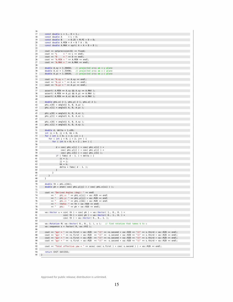
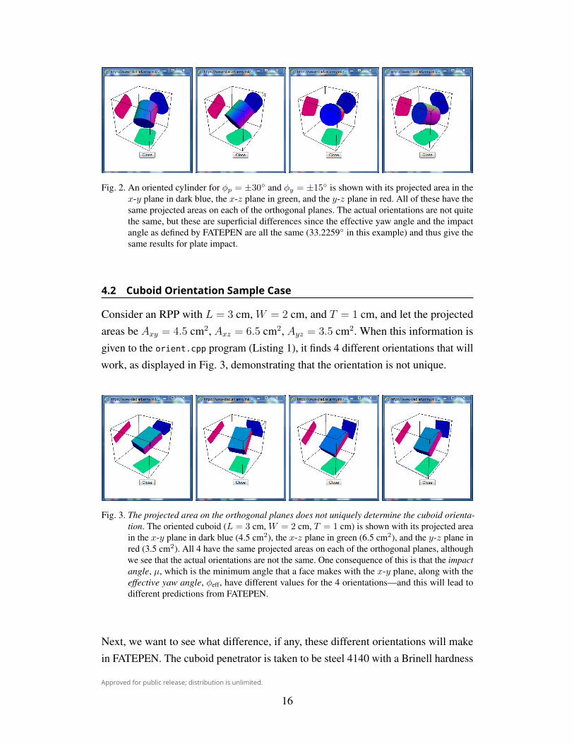
4.1 Cylinder Orientation Sample CaseConsider an RCC with L = 1, D = 1, φp = 30◦, and φy = 15◦. The projected areasare found to be Ayz = 1.16920, Axz = 1.25496, and Axy = 1.20494. Using thesevalues for the projected areas, the program in Listing 2 computes φp = ±30◦ andφy = ±15◦, with the 4 possible orientations displayed in Fig. 2.
Listing 2. rcc.cpp1 // rcc.cpp: compute pitch and yaw from area projections for an RCC (sample case)2 // R. Saucier, June 2006 (Revised October 2015)34 #include "Rotation.h"5 #include <iostream>6 #include <cmath>7 #include <cstdlib>8 #include <cassert>9 #include <iomanip>
10 using namespace std;1112 double angle1( double a, double b, double c ) { return asin( c / sqrt( a * a + b * b ) ) - atan( b / a ); }13 double angle2( double a, double b, double c ) { return M_PI - asin( c / sqrt( a * a + b * b ) ) - atan( b / a ); }1415 int main( void ) {
14
Approved for public release; distribution is unlimited.
1617 const double L = 1., D = 1.;18 const double A = L * D;19 const double B = 0.25 * M_PI * D * D;20 const double A_MIN = A < B ? A : B;21 const double A_MAX = sqrt( A * A + B * B );2223 cout << setprecision(6) << fixed;24 cout << "L = " << L << endl;25 cout << "D = " << D << endl;26 cout << "A_MIN = " << A_MIN << endl;27 cout << "A_MAX = " << A_MAX << endl;2829 double A_xy = 1.20494; // projected area on x-y plane30 double A_xz = 1.25496; // projected area on x-z plane31 double A_yz = 1.16920; // projected area on y-z plane3233 cout << "A_xy = " << A_xy << endl;34 cout << "A_xz = " << A_xz << endl;35 cout << "A_yz = " << A_yz << endl;3637 assert( A_MIN <= A_xy && A_xy <= A_MAX );38 assert( A_MIN <= A_yz && A_yz <= A_MAX );39 assert( A_MIN <= A_xz && A_xz <= A_MAX );4041 double phi_x[ 2 ], phi_y[ 2 ], phi_z[ 2 ];42 phi_x[0] = angle1( A, B, A_yz );43 phi_x[1] = angle2( A, B, A_yz );4445 phi_y[0] = angle1( A, B, A_xz );46 phi_y[1] = angle2( A, B, A_xz );4748 phi_z[0] = angle1( A, B, A_xy );49 phi_z[1] = angle2( A, B, A_xy );5051 double d, delta = 1.e36;52 int ii = 0, jj = 0, kk = 0;53 for ( int i = 0; i < 2; i++ ) {54 for ( int j = 0; j < 2; j++ ) {55 for ( int k = 0; k < 2 ; k++ ) {5657 d = cos( phi_x[i] ) * cos( phi_x[i] ) +58 cos( phi_y[j] ) * cos( phi_y[j] ) +59 cos( phi_z[k] ) * cos( phi_z[k] );60 if ( fabs( d - 1. ) < delta ) {61 ii = i;62 jj = j;63 kk = k;64 delta = fabs( d - 1. );65 }66 }67 }68 }6970 double th = phi_z[kk];71 double ph = atan( cos( phi_y[jj] ) / cos( phi_x[ii] ) );7273 cout << "Derived Angles (deg): " << endl74 << " phi_x: " << phi_x[ii] * va::R2D << endl75 << " phi_y: " << phi_y[jj] * va::R2D << endl76 << " phi_z: " << phi_z[kk] * va::R2D << endl77 << " theta: " << th * va::R2D << endl78 << " phi: " << ph * va::R2D << endl;7980 va::Vector u = sin( th ) * cos( ph ) * va::Vector( 1., 0., 0. ) +81 sin( th ) * sin( ph ) * va::Vector( 0., 1., 0. ) +82 cos( th ) * va::Vector( 0., 0., 1. );8384 va::Rotation R( va::Vector( 0., 0., 1. ), u ); // find rotation that takes k to u85 va::sequence s = factor( R, va::XYZ );8687 cout << "pyr = " << +s.first * va::R2D << "\t" << +s.second * va::R2D << "\t" << s.third * va::R2D << endl;88 cout << "pyr = " << +s.first * va::R2D << "\t" << -s.second * va::R2D << "\t" << s.third * va::R2D << endl;89 cout << "pyr = " << -s.first * va::R2D << "\t" << +s.second * va::R2D << "\t" << s.third * va::R2D << endl;90 cout << "pyr = " << -s.first * va::R2D << "\t" << -s.second * va::R2D << "\t" << s.third * va::R2D << endl;9192 cout << "Total effective yaw = " << acos( cos( s.first ) * cos( s.second ) ) * va::R2D << endl;9394 return EXIT_SUCCESS;95 }
15
Approved for public release; distribution is unlimited.
Fig. 2. An oriented cylinder for φp = ±30◦ and φy = ±15◦ is shown with its projected area in thex-y plane in dark blue, the x-z plane in green, and the y-z plane in red. All of these have thesame projected areas on each of the orthogonal planes. The actual orientations are not quitethe same, but these are superficial differences since the effective yaw angle and the impactangle as defined by FATEPEN are all the same (33.2259◦ in this example) and thus give thesame results for plate impact.
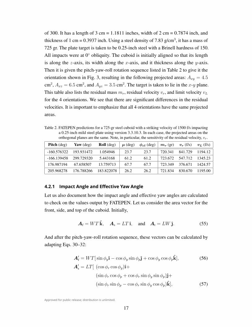
4.2 Cuboid Orientation Sample CaseConsider an RPP with L = 3 cm, W = 2 cm, and T = 1 cm, and let the projectedareas be Axy = 4.5 cm2, Axz = 6.5 cm2, Ayz = 3.5 cm2. When this information isgiven to the orient.cpp program (Listing 1), it finds 4 different orientations that willwork, as displayed in Fig. 3, demonstrating that the orientation is not unique.
Fig. 3. The projected area on the orthogonal planes does not uniquely determine the cuboid orienta-tion. The oriented cuboid (L = 3 cm, W = 2 cm, T = 1 cm) is shown with its projected areain the x-y plane in dark blue (4.5 cm2), the x-z plane in green (6.5 cm2), and the y-z plane inred (3.5 cm2). All 4 have the same projected areas on each of the orthogonal planes, althoughwe see that the actual orientations are not the same. One consequence of this is that the impactangle, µ, which is the minimum angle that a face makes with the x-y plane, along with theeffective yaw angle, φeff, have different values for the 4 orientations—and this will lead todifferent predictions from FATEPEN.
Next, we want to see what difference, if any, these different orientations will makein FATEPEN. The cuboid penetrator is taken to be steel 4140 with a Brinell hardness
16
Approved for public release; distribution is unlimited.
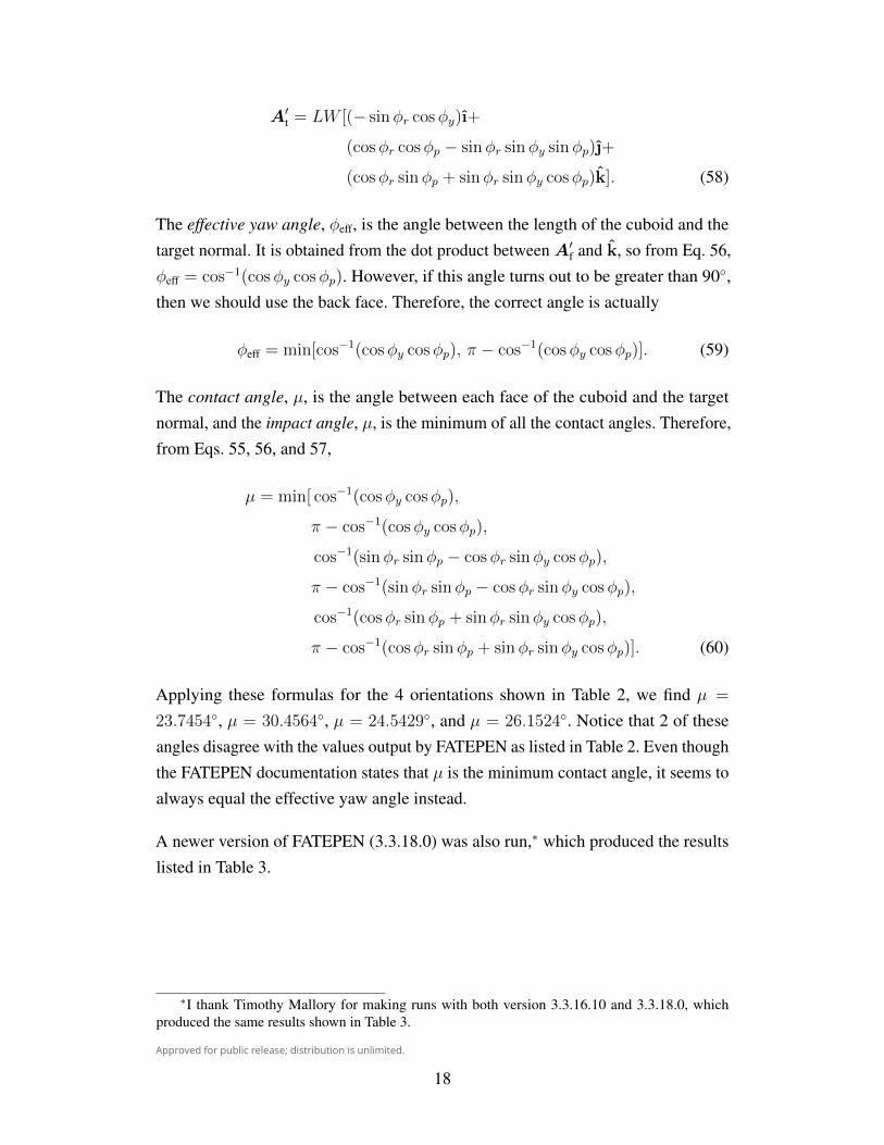
of 300. It has a length of 3 cm = 1.1811 inches, width of 2 cm = 0.7874 inch, andthickness of 1 cm = 0.3937 inch. Using a steel density of 7.83 g/cm3, it has a mass of725 gr. The plate target is taken to be 0.25-inch steel with a Brinell hardness of 150.All impacts were at 0◦ obliquity. The cuboid is initially aligned so that its lengthis along the z-axis, its width along the x-axis, and it thickness along the y-axis.Then it is given the pitch-yaw-roll rotation sequence listed in Table 2 to give it theorientation shown in Fig. 3, resulting in the following projected areas: Axy = 4.5
cm2, Axz = 6.5 cm2, and Ayz = 3.5 cm2. The target is taken to lie in the x-y plane.This table also lists the residual mass mr, residual velocity vr, and limit velocity vLfor the 4 orientations. We see that there are significant differences in the residualvelocities. It is important to emphasize that all 4 orientations have the same projectedareas.
Table 2. FATEPEN predictions for a 725-gr steel cuboid with a striking velocity of 1500 f/s impactinga 0.25-inch mild steel plate using version 3.3.10.3. In each case, the projected areas on theorthogonal planes are the same. Note, in particular, the sensitivity of the residual velocity, vr.
Pitch (deg) Yaw (deg) Roll (deg) µ (deg) φeff (deg) mr (gr) vr (f/s) vL (f/s)
-160.576322 193.931472 1.054946 23.7 23.7 720.341 841.729 1194.12
-166.139458 299.729320 5.443168 61.2 61.2 723.672 547.712 1345.23
176.987194 67.658507 13.759713 67.7 67.7 723.349 376.671 1424.57
205.968278 176.788266 183.822078 26.2 26.2 721.834 830.670 1195.00
4.2.1 Impact Angle and Effective Yaw AngleLet us also document how the impact angle and effective yaw angles are calculatedto check on the values output by FATEPEN. Let us consider the area vector for thefront, side, and top of the cuboid. Initially,
Af = WT k, As = LT ı, and At = LW . (55)
And after the pitch-yaw-roll rotation sequence, these vectors can be calculated byadapting Eqs. 30–32:
A′f = WT [ sinφyı− cosφy sinφp + cosφy cosφpk], (56)
A′s = LT [ (cosφr cosφy )ı+
(sinφr cosφp + cosφr sinφy sinφp)+
(sinφr sinφp − cosφr sinφy cosφp)k], (57)
17
Approved for public release; distribution is unlimited.
A′t = LW [(− sinφr cosφy )ı+
(cosφr cosφp − sinφr sinφy sinφp)+
(cosφr sinφp + sinφr sinφy cosφp)k]. (58)
The effective yaw angle, φeff, is the angle between the length of the cuboid and thetarget normal. It is obtained from the dot product betweenA′f and k, so from Eq. 56,φeff = cos−1(cosφy cosφp). However, if this angle turns out to be greater than 90◦,then we should use the back face. Therefore, the correct angle is actually
φeff = min[cos−1(cosφy cosφp), π − cos−1(cosφy cosφp)]. (59)
The contact angle, µ, is the angle between each face of the cuboid and the targetnormal, and the impact angle, µ, is the minimum of all the contact angles. Therefore,from Eqs. 55, 56, and 57,
µ = min[ cos−1(cosφy cosφp),
π − cos−1(cosφy cosφp),
cos−1(sinφr sinφp − cosφr sinφy cosφp),
π − cos−1(sinφr sinφp − cosφr sinφy cosφp),
cos−1(cosφr sinφp + sinφr sinφy cosφp),
π − cos−1(cosφr sinφp + sinφr sinφy cosφp)]. (60)
Applying these formulas for the 4 orientations shown in Table 2, we find µ =
23.7454◦, µ = 30.4564◦, µ = 24.5429◦, and µ = 26.1524◦. Notice that 2 of theseangles disagree with the values output by FATEPEN as listed in Table 2. Even thoughthe FATEPEN documentation states that µ is the minimum contact angle, it seems toalways equal the effective yaw angle instead.
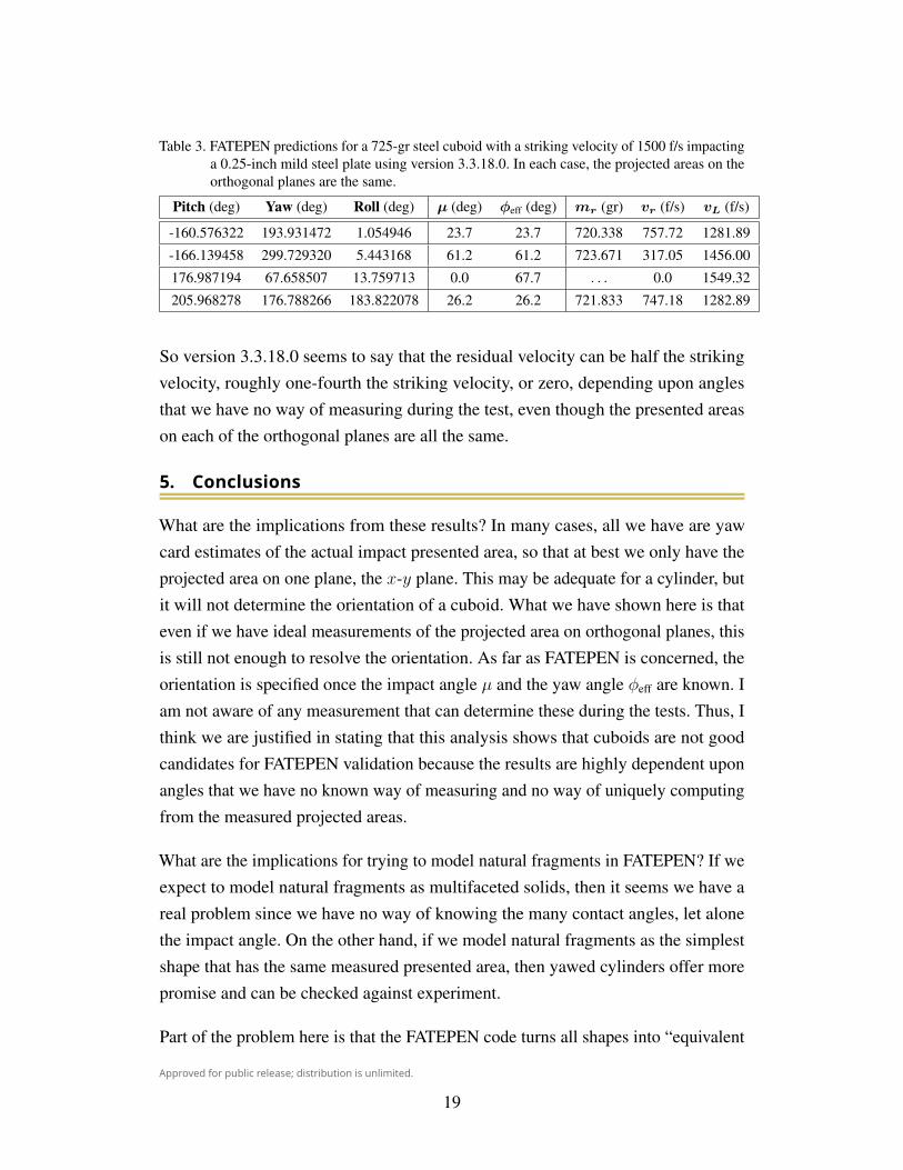
A newer version of FATEPEN (3.3.18.0) was also run,∗ which produced the resultslisted in Table 3.
∗I thank Timothy Mallory for making runs with both version 3.3.16.10 and 3.3.18.0, whichproduced the same results shown in Table 3.
18
Approved for public release; distribution is unlimited.
Table 3. FATEPEN predictions for a 725-gr steel cuboid with a striking velocity of 1500 f/s impactinga 0.25-inch mild steel plate using version 3.3.18.0. In each case, the projected areas on theorthogonal planes are the same.
Pitch (deg) Yaw (deg) Roll (deg) µ (deg) φeff (deg) mr (gr) vr (f/s) vL (f/s)
-160.576322 193.931472 1.054946 23.7 23.7 720.338 757.72 1281.89
-166.139458 299.729320 5.443168 61.2 61.2 723.671 317.05 1456.00
176.987194 67.658507 13.759713 0.0 67.7 . . . 0.0 1549.32
205.968278 176.788266 183.822078 26.2 26.2 721.833 747.18 1282.89
So version 3.3.18.0 seems to say that the residual velocity can be half the strikingvelocity, roughly one-fourth the striking velocity, or zero, depending upon anglesthat we have no way of measuring during the test, even though the presented areason each of the orthogonal planes are all the same.
5. ConclusionsWhat are the implications from these results? In many cases, all we have are yawcard estimates of the actual impact presented area, so that at best we only have theprojected area on one plane, the x-y plane. This may be adequate for a cylinder, butit will not determine the orientation of a cuboid. What we have shown here is thateven if we have ideal measurements of the projected area on orthogonal planes, thisis still not enough to resolve the orientation. As far as FATEPEN is concerned, theorientation is specified once the impact angle µ and the yaw angle φeff are known. Iam not aware of any measurement that can determine these during the tests. Thus, Ithink we are justified in stating that this analysis shows that cuboids are not goodcandidates for FATEPEN validation because the results are highly dependent uponangles that we have no known way of measuring and no way of uniquely computingfrom the measured projected areas.
What are the implications for trying to model natural fragments in FATEPEN? If weexpect to model natural fragments as multifaceted solids, then it seems we have areal problem since we have no way of knowing the many contact angles, let alonethe impact angle. On the other hand, if we model natural fragments as the simplestshape that has the same measured presented area, then yawed cylinders offer morepromise and can be checked against experiment.
Part of the problem here is that the FATEPEN code turns all shapes into “equivalent
19

Approved for public release; distribution is unlimited.
cylinders”.∗ So while we may be able to compute the contact angle of each faceof the cuboid, that is not necessarily the shape that the FATEPEN code is dealingwith at impact. We are much better off using cylinders since we can be assured thatFATEPEN is using the same shape. Further, it is more robust since we only needto control the impact presented area and there is only one contact angle, which isthe angle the RCC face makes with the target normal. Once we know the impactpresented area and the cylinder dimensions, the impact angle is uniquely determined.See Appendix B for an implementation of this procedure.
∗See Yatteau et al.,5 Section 2.1.4 on p. 2-5 and Section 4.1 on p. 4-1.
20
Approved for public release; distribution is unlimited.
6. References
1. Yatteau JD, Zernow RH, Recht GW, Edquist KT. FATEPEN. Version 3.0.0b.Terminal Ballistic Penetration Model. Applied Research Associates (ARA)Project 4714, prepared for Naval Surface Warfare Center, Dahlgren, VA; 1999Jan.
2. Project THOR. The resistance of various metallic materials to perforation bysteel fragments: empirical relationships for fragment residual velocity and resid-ual weight. Aberdeen Proving Ground (MD): Army Ballistic Research Labora-tory (US); 1961 Apr. Report No.: TR-47.
3. Kuipers JB. Quaternions and rotation sequences: a primer with applications toorbits, aerospace, and virtual reality. Princeton (NJ): Princeton University Press;2002.
4. Mallory TD. FATEPEN steel-on-steel V50 estimates. Aberdeen Proving Ground(MD): Army Research Laboratory (US); unpublished paper, 2015 Nov.
5. Yatteau JD, Zernow RH, Recht GW, Edquist KT. FATEPEN fast air targetencounter penetration (Ver. 3.0.0) terminal ballistic penetration model. Little-ton (CO): Applied Research Associates, Inc.; 2001 Sep., revised 2005 Feb 2.(Analyst’s manual; vol. 1).
21

Approved for public release; distribution is unlimited.
INTENTIONALLY LEFT BLANK.
22

Approved for public release; distribution is unlimited.
Appendix A. Formula for an Euler Sequence of Rotations
23
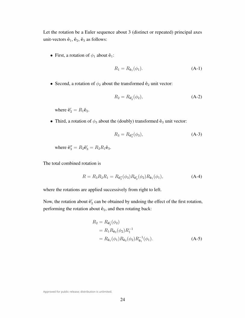
Approved for public release; distribution is unlimited.
Let the rotation be a Euler sequence about 3 (distinct or repeated) principal axesunit-vectors e1, e2, e3 as follows:
• First, a rotation of φ1 about e1:
R1 = Re1(φ1). (A-1)
• Second, a rotation of φ2 about the transformed e2 unit vector:
R2 = Re′2(φ2), (A-2)
where e′2 = R1e2.
• Third, a rotation of φ3 about the (doubly) transformed e3 unit vector:
R3 = Re′′3(φ3), (A-3)
where e′′3 = R2e′3 = R2R1e3.
The total combined rotation is
R = R3R2R1 = Re′′3(φ3)Re′
2(φ2)Re1(φ1), (A-4)
where the rotations are applied successively from right to left.
Now, the rotation about e′2 can be obtained by undoing the effect of the first rotation,performing the rotation about e2, and then rotating back:
R2 = Re′2(φ2)
= R1Re2(φ2)R−11
= Re1(φ1)Re2(φ2)R−1e1(φ1). (A-5)
24
Approved for public release; distribution is unlimited.
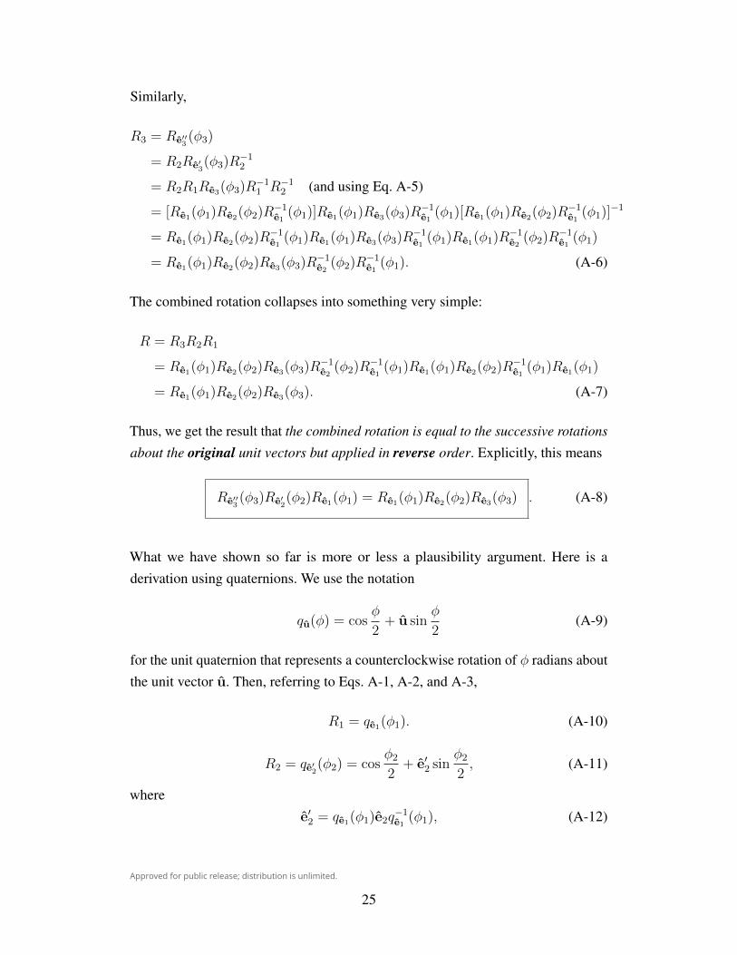
Similarly,
R3 = Re′′3(φ3)
= R2Re′3(φ3)R
−12
= R2R1Re3(φ3)R−11 R−12 (and using Eq. A-5)
= [Re1(φ1)Re2(φ2)R−1e1(φ1)]Re1(φ1)Re3(φ3)R
−1e1(φ1)[Re1(φ1)Re2(φ2)R
−1e1(φ1)]
−1
= Re1(φ1)Re2(φ2)R−1e1(φ1)Re1(φ1)Re3(φ3)R
−1e1(φ1)Re1(φ1)R
−1e2(φ2)R
−1e1(φ1)
= Re1(φ1)Re2(φ2)Re3(φ3)R−1e2(φ2)R
−1e1(φ1). (A-6)
The combined rotation collapses into something very simple:
R = R3R2R1
= Re1(φ1)Re2(φ2)Re3(φ3)R−1e2(φ2)R
−1e1(φ1)Re1(φ1)Re2(φ2)R
−1e1(φ1)Re1(φ1)
= Re1(φ1)Re2(φ2)Re3(φ3). (A-7)
Thus, we get the result that the combined rotation is equal to the successive rotations
about the original unit vectors but applied in reverse order. Explicitly, this means
Re′′3(φ3)Re′
2(φ2)Re1(φ1) = Re1(φ1)Re2(φ2)Re3(φ3) . (A-8)
What we have shown so far is more or less a plausibility argument. Here is aderivation using quaternions. We use the notation
qu(φ) = cosφ
2+ u sin
φ
2(A-9)
for the unit quaternion that represents a counterclockwise rotation of φ radians aboutthe unit vector u. Then, referring to Eqs. A-1, A-2, and A-3,
R1 = qe1(φ1). (A-10)
R2 = qe′2(φ2) = cos
φ2
2+ e′2 sin
φ2
2, (A-11)
wheree′2 = qe1(φ1)e2q
−1e1(φ1), (A-12)
25
Approved for public release; distribution is unlimited.
so that
qe′2(φ2) = cos
φ2
2+ e′2 sin
φ2
2
= cosφ2
2+ qe1(φ1)e2q
−1e1(φ1) sin
φ2
2
= qe1(φ1)
(cos
φ2
2+ e2 sin
φ2
2
)q−1e1
(φ1)
= qe1(φ1)qe2(φ2)q−1e1(φ1), (A-13)
andR3 = qe′′
3(φ3) = cos
φ3
2+ e′′3 sin
φ3
2, (A-14)
where
e′′3 = qe′2(φ2)e
′3q−1e′2(φ2)
= qe′2(φ2)qe1(φ1)e3q
−1e1(φ1)q
−1e′2(φ2)
= [qe1(φ1)qe2(φ2)q−1e1(φ1)]qe1(φ1)e3q
−1e1(φ1)[qe1(φ1)qe2(φ2)q
−1e1(φ1)]
−1
= qe1(φ1)qe2(φ2)q−1e1(φ1)qe1(φ1)e3q
−1e1(φ1)qe1(φ1)q
−1e2(φ2)q
−1e1(φ1)
= qe1(φ1)qe2(φ2)e3q−1e2(φ2)q
−1e1(φ1), (A-15)
so that
qe′′3(φ3) = cos
φ3
2+ e′′3 sin
φ3
2
= cosφ3
2+ qe1(φ1)qe2(φ2)e3q
−1e2(φ2)q
−1e1(φ1) sin
φ3
2
= qe1(φ1)qe2(φ2)
(cos
φ3
2+ e3 sin
φ3
2
)q−1e2
(φ2)q−1e1(φ1)
= qe1(φ1)qe2(φ2)qe3(φ3)q−1e2(φ2)q
−1e1(φ1). (A-16)
Therefore, the total combined rotation is
R = R3R2R1 = qe′′3(φ3)qe′
2(φ2)qe1(φ1)
= [qe1(φ1)qe2(φ2)qe3(φ3)q−1e2(φ2)q
−1e1(φ1)][qe1(φ1)qe2(φ2)q
−1e1(φ1)]qe1(φ1)
= qe1(φ1)qe2(φ2)qe3(φ3), (A-17)
as was to be shown.
26
Approved for public release; distribution is unlimited.
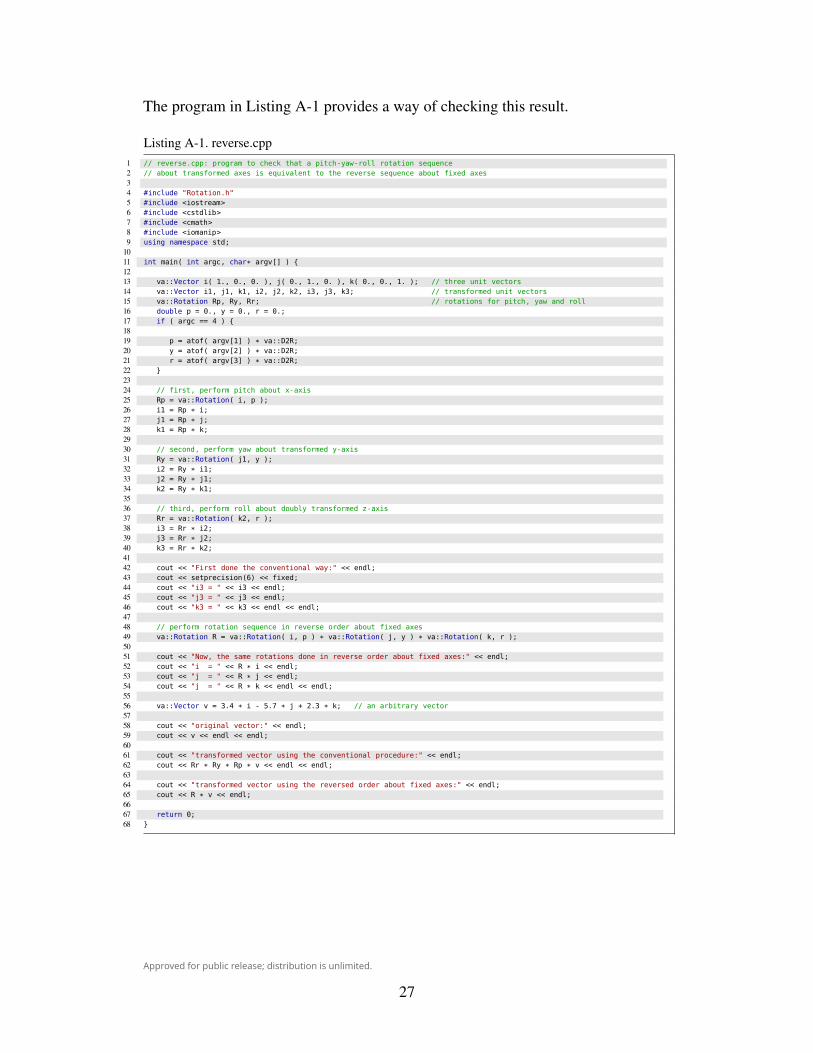
The program in Listing A-1 provides a way of checking this result.
Listing A-1. reverse.cpp1 // reverse.cpp: program to check that a pitch-yaw-roll rotation sequence2 // about transformed axes is equivalent to the reverse sequence about fixed axes34 #include "Rotation.h"5 #include <iostream>6 #include <cstdlib>7 #include <cmath>8 #include <iomanip>9 using namespace std;
1011 int main( int argc, char* argv[] ) {1213 va::Vector i( 1., 0., 0. ), j( 0., 1., 0. ), k( 0., 0., 1. ); // three unit vectors14 va::Vector i1, j1, k1, i2, j2, k2, i3, j3, k3; // transformed unit vectors15 va::Rotation Rp, Ry, Rr; // rotations for pitch, yaw and roll16 double p = 0., y = 0., r = 0.;17 if ( argc == 4 ) {1819 p = atof( argv[1] ) * va::D2R;20 y = atof( argv[2] ) * va::D2R;21 r = atof( argv[3] ) * va::D2R;22 }2324 // first, perform pitch about x-axis25 Rp = va::Rotation( i, p );26 i1 = Rp * i;27 j1 = Rp * j;28 k1 = Rp * k;2930 // second, perform yaw about transformed y-axis31 Ry = va::Rotation( j1, y );32 i2 = Ry * i1;33 j2 = Ry * j1;34 k2 = Ry * k1;3536 // third, perform roll about doubly transformed z-axis37 Rr = va::Rotation( k2, r );38 i3 = Rr * i2;39 j3 = Rr * j2;40 k3 = Rr * k2;4142 cout << "First done the conventional way:" << endl;43 cout << setprecision(6) << fixed;44 cout << "i3 = " << i3 << endl;45 cout << "j3 = " << j3 << endl;46 cout << "k3 = " << k3 << endl << endl;4748 // perform rotation sequence in reverse order about fixed axes49 va::Rotation R = va::Rotation( i, p ) * va::Rotation( j, y ) * va::Rotation( k, r );5051 cout << "Now, the same rotations done in reverse order about fixed axes:" << endl;52 cout << "i = " << R * i << endl;53 cout << "j = " << R * j << endl;54 cout << "j = " << R * k << endl << endl;5556 va::Vector v = 3.4 * i - 5.7 * j + 2.3 * k; // an arbitrary vector5758 cout << "original vector:" << endl;59 cout << v << endl << endl;6061 cout << "transformed vector using the conventional procedure:" << endl;62 cout << Rr * Ry * Rp * v << endl << endl;6364 cout << "transformed vector using the reversed order about fixed axes:" << endl;65 cout << R * v << endl;6667 return 0;68 }
27

Approved for public release; distribution is unlimited.
For example, the commands1 c++ -O2 -Wall -std=c++11 -o reverse reverse.cpp -lm2 ./reverse 65. -137. 54.
will print the results1 First done the conventional way:2 i3 = -0.429879 -0.021405 0.9026333 j3 = 0.591678 0.748463 0.2995354 k3 = -0.681998 0.662832 -0.30908356 Now, the same rotations done in reverse order about fixed axes:7 i = -0.429879 -0.021405 0.9026338 j = 0.591678 0.748463 0.2995359 j = -0.681998 0.662832 -0.309083
1011 original vector:12 3.400000 -5.700000 2.3000001314 transformed vector using the conventional procedure:15 -6.402747 -2.814501 0.6507071617 transformed vector using the reversed order about fixed axes:18 -6.402747 -2.814501 0.650707
28

Approved for public release; distribution is unlimited.
Appendix B. Yaw Angle of a Cylinder as a Function of Shape Factor
29
Approved for public release; distribution is unlimited.
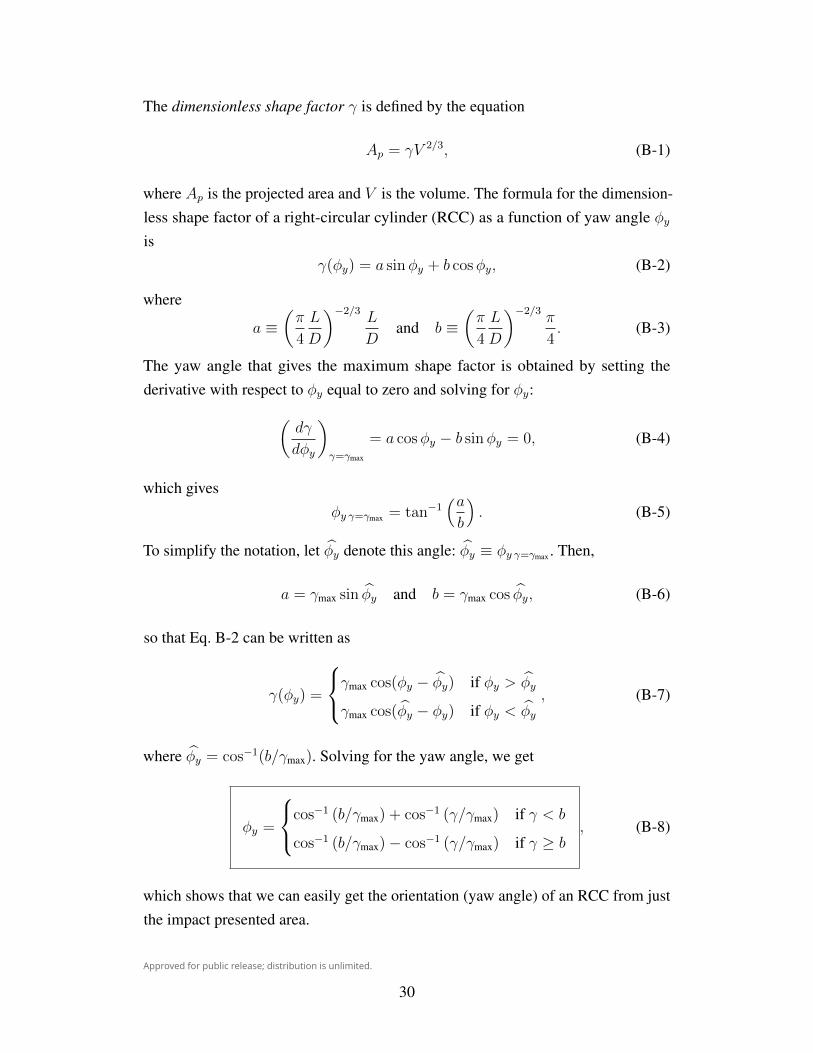
The dimensionless shape factor γ is defined by the equation
Ap = γV 2/3, (B-1)
where Ap is the projected area and V is the volume. The formula for the dimension-less shape factor of a right-circular cylinder (RCC) as a function of yaw angle φyis
γ(φy) = a sinφy + b cosφy, (B-2)
where
a ≡(π
4
L
D
)−2/3L
Dand b ≡
(π
4
L
D
)−2/3π
4. (B-3)
The yaw angle that gives the maximum shape factor is obtained by setting thederivative with respect to φy equal to zero and solving for φy:(
dγ
dφy
)γ=γmax
= a cosφy − b sinφy = 0, (B-4)
which givesφy γ=γmax = tan−1
(ab
). (B-5)
To simplify the notation, let φy denote this angle: φy ≡ φy γ=γmax . Then,
a = γmax sin φy and b = γmax cos φy, (B-6)
so that Eq. B-2 can be written as
γ(φy) =
γmax cos(φy − φy) if φy > φy
γmax cos(φy − φy) if φy < φy, (B-7)
where φy = cos−1(b/γmax). Solving for the yaw angle, we get
φy =
cos−1 (b/γmax) + cos−1 (γ/γmax) if γ < b
cos−1 (b/γmax)− cos−1 (γ/γmax) if γ ≥ b, (B-8)
which shows that we can easily get the orientation (yaw angle) of an RCC from justthe impact presented area.
30
Approved for public release; distribution is unlimited.
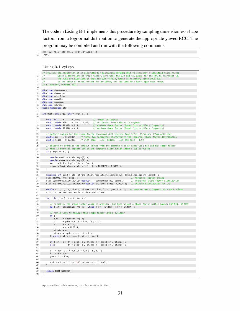
The code in Listing B-1 implements this procedure by sampling dimensionless shapefactors from a lognormal distribution to generate the appropriate yawed RCC. Theprogram may be compiled and run with the following commands:
1 c++ -O2 -Wall -std=c++11 -o cyl cyl.cpp -lm2 ./cyl
Listing B-1. cyl.cpp1 // cyl.cpp: Implementation of an algorithm for generating FATEPEN RCCs to represent a specified shape factor.2 // Given a dimensionless shape factor, generates the L/D and yaw angle for the RCC to represent it.3 // The RCCs are disk-like in that the L/D <= Pi/4, which is necessary since [0.5,4.5]4 // is the range of shape factors for artillery and rod-like RCCs don’t span this range.5 // R. Saucier, October 201167 #include <iostream>8 #include <iomanip>9 #include <cstdlib>
10 #include <cmath>11 #include <random>12 #include <chrono>13 using namespace std;1415 int main( int argc, char* argv[] ) {1617 const int N = 1000; // number of samples18 const double R2D = 180. / M_PI; // to convert from radians to degrees19 const double SF_MIN = 0.5; // minimum shape factor (found from artillery fragments)20 const double SF_MAX = 4.5; // maximum shape factor (found from artillery fragments)2122 // default values for the shape factor lognormal distribution from 122mm, 152mm and 155mm artillery23 double mu = 0.590494; // these two parameters characterize the lognormal shape factor distribution24 double sigma = 0.323433; // with mode = 1.63, median = 1.80 and mean = 1.902526 // ability to override the default values from the command line by specifying min and max shape factor27 // that is meant to capture 95% of the complete distribution (from 0.025 to 0.975)28 if ( argc == 3 ) {2930 double sfmin = atof( argv[1] );31 double sfmax = atof( argv[2] );32 mu = 0.5 * log( sfmin * sfmax );33 sigma = log( sfmax / sfmin ) / ( 2. * M_SQRT2 * 1.3859 );34 }3536 unsigned int seed = std::chrono::high_resolution_clock::now().time_since_epoch().count();37 std::mt19937 rng( seed ); // Mersenne Twister engine38 std::lognormal_distribution<double> lognormal( mu, sigma ); // lognormal shape factor distribution39 std::uniform_real_distribution<double> uniform( 0.069, M_PI_4 ); // uniform distribution for L/D4041 double a, b, c, th, sf_min, sf_max, sf, l_d, l, d, yaw, V = 1.; // here we use a fragment with unit volume42 std::cout << std::setprecision(6) <<std::fixed;4344 for ( int n = 0; n < N; n++ ) {4546 // normally, the shape factor would be provided, but here we get a shape factor within bounds [SF_MIN, SF_MAX]47 do { sf = lognormal( rng ); } while ( sf < SF_MIN || sf > SF_MAX );4849 // now we want to realize this shape factor with a cylinder50 do {51 l_d = uniform( rng );52 c = pow( M_PI_4 * l_d, -2./3. );53 a = c * l_d;54 b = c * M_PI_4;55 sf_min = a;56 sf_max = sqrt( a * a + b * b );57 } while ( sf < sf_min || sf > sf_max );5859 if ( sf < b ) th = acos( b / sf_max ) + acos( sf / sf_max );60 else th = acos( b / sf_max ) - acos( sf / sf_max );6162 d = pow( V / ( M_PI_4 * l_d ), 1./3. );63 l = d * l_d;64 yaw = th * R2D;6566 std::cout << l_d << "\t" << yaw << std::endl;67 }6869 return EXIT_SUCCESS;70 }
31

Approved for public release; distribution is unlimited.
INTENTIONALLY LEFT BLANK.
32

Approved for public release; distribution is unlimited.
List of Symbols, Abbreviations, and Acronyms
TERMS:
FATEPEN: Fast Air Target Encounter Penetration
RCC: right-circular cylinder
RPP: rectangular parallelepiped
MATHEMATICAL SYMBOLS:
Re(θ): Rotation about the unit vector e through the angle θ
33
Approved for public release; distribution is unlimited.
1(PDF)
DEFENSE TECHNICALINFORMATION CTRDTIC OCA
2(PDF)
DIRECTORUS ARMY RESEARCH LABRDRL CIO LLIMAL HRA MAIL & RECORDS MGMT
1(PDF)
GOVT PRINTG OFCA MALHOTRA
1(HC)
NVL SURFC WARFARE CTRATTN: D DICKINSON G246138 NORC AVE STE 313DAHLGREN VA 22448-5157
1(HC)
APPLIED RESEARCH ASSOCIATESATTN: R ZERNOW10720 BRADFORD RD STE 110LITTLETON CO 80127-4298
ABERDEEN PROVING GROUND
8(PDF)
RDRL SLB DJ COLLINS
RDRL SLB GD CARABETTAT MALLORY
RDRL SLB SJ AUTENR DIBELKAS MORRISONN REEDR SAUCIER
1(HC)
R SAUCIER
34