Embed Size (px)
Citation preview

RESOLUTION MEPC.66(37) ADOPTED ON 14 SEPTEMBER 1995
INTERIM GUIDELINES FOR APPROVAL OF ALTERNATIVE METHODS OF DESIGN AND CONSTRUCTION OF OIL TANKERS UNDER
REGULATION 13F(5) OF ANNEX I OF MARPOL 73/78

MEPC 37/zz/Add,.T
AI\NEX 16
RESOLUTTON MEPC.66(37)
ADOPTED ON 14 SEPTEMBER 1995
INTERIM GUIDELINES FOR APPROVAL OF ALTERNATIVE METHODSOF DESIGN AND CONSTRUCTION OF OIL TANKERS UNDER
REGULATION 13F(s) OF AI\NEX I OF MARPOL 73178
THE MARINE ENVIRONMENT PROTECTION COMMITTEE,
RECALLING Article 38(a) of the Convention on the Intemational Maritime Organizationconceming the functions of the Committee,
NOTING resolution MEPC.52(32) by which the Committee adopted new regulations l3F and
i3G and related amendments to Annex I of MARPOLT3/78,
NOTING FURTHER, resolution MEPC.52(32) by which the Committee agreed to develop, as
a matter of urgency, Guidelines for approval of altemative methods of design and construction of oiltankers as called for in regulation l3F(5),
HAVING CONSIDEREI), at its thirty-seventh session, the interim guidelines developed under
regulation l3F(5) of Annex I of MARPOL73178,
l. ADOPTS the Interim Guidelines for Approval of Alternative Methods of Design and
Construction of Oil Tankers under regulation 13F(5), the text of which is set out at Annex to this
resolution;
2. INVITES Govemments to give due consideration to the interim guidelines when evaluating other
methods of design and construction of oil tankers as altematives to the requirements prescribed inparagraph (3) of regulation l3F of Annex I of MARPOL73178, for submission of such design to the
Committee for approval in principle;
3. RDSOLVES to keep the interim guidelines under regulation 13F(5) under review and develop
final guidelines in the light of experience gained.
I:\MEPC\37\22-Al(2)
RESOLUTION MEPC.66(37) ADOPTED ON 14 SEPTEMBER 1995
INTERIM GUIDELINES FOR APPROVAL OF ALTERNATIVE METHODS OF DESIGN AND CONSTRUCTION OF OIL TANKERS UNDER
REGULATION 13F(5) OF ANNEX I OF MARPOL 73/78

MEPC 37/22tfudd.rANNEX 16
Page2
ANNEX
Interim Guidelines for the Approval of AlternativeMethods of Design and Construction of Oil
Tankers under Regulation 13f(5)of Annex I of IVÍARPOL73178
Contents
Preamble
1. General
Applicability ..............
Approval procedure for alternative tanker designs .
Oil outflow analysis
4.I General
4.2 Pollution prevention index.........
4.3 Calculation of oil outflow parameters ...............
Assumptions fol' calculating oil outflow parameters
6.
5.2' Damage assumptions ................. ....,...................
Probabilistic methodology for calculating oil outflow
6.1 Damage c¿ßes .........
6.2 Oil outflow calculations
Reference double hull designs ................
FiguresS-8..........
Page
2
3
4
3
4
4
5
5
)
6
7
7
7
9
T2
I2
T2
t2
5
7
l8-21
I:MEPC\37\22-Al(2)
RESOLUTION MEPC.66(37) ADOPTED ON 14 SEPTEMBER 1995
INTERIM GUIDELINES FOR APPROVAL OF ALTERNATIVE METHODS OF DESIGN AND CONSTRUCTION OF OIL TANKERS UNDER
REGULATION 13F(5) OF ANNEX I OF MARPOL 73/78

MEPC 37/22l{dd.rANNEX 16
Page 3
Preamble
1. The purpose of these lnterim Guidelines hereunder referred to as the Guidelines is to provide an
intemational standard for the evaluation and approval of altemative methods of designs and construction
of oil tankers under regulation l3F(5) of Annex I of MARPOLT3/78.
2. The basic philosophy of the Guidelines is to compare the oil outflow performance in case ofcollision or stranding of an alternative tanker design to that of ref erence double hull designs
complying with regulation i3F(3) on the basis of a calculated pollution prevention index.
The oil outflow performance of double hull tankers which comply with regulation l3F(3) may
be different. The longitudinal subdivision of the cargo tanks has a major influence on the oil outflowin case of inner hull penetration. The selected reference double hull designs exhibit a favourable oiloutflow performance.
3. The calculation of oil outflow is based on the probabilistic methodology and best available
tanker accident damage statistics. Re-appraisal of the Guidelines may be appropriate when more
information on tanker accident damage has become available and more experience with the application
of these Guidelines has been gained.
4. Falling tides will have an adverse effect on oil outflow from a stranded tanker and the
Guidelines take account of this. The tide values specified in Section 5 represent realistic average tidal
changes which have been chosen to identify the influence of tidal changes on the oil outflow in case
of stranding.
I : \lvf EP C\3 7 \22 - Al (2)
RESOLUTION MEPC.66(37) ADOPTED ON 14 SEPTEMBER 1995
INTERIM GUIDELINES FOR APPROVAL OF ALTERNATIVE METHODS OF DESIGN AND CONSTRUCTION OF OIL TANKERS UNDER
REGULATION 13F(5) OF ANNEX I OF MARPOL 73/78

MEPC 37l22t^dd.rANNEX 16
Page 4
1. General
l.l Regulation l3F of Annex I of OL 73/78 specifies structural requirements for new tankers of600 tdw and above, contracted on or after 6 July 1993. Paragraph (3) of the regulation requirestankers of 5000 tdw and above to be equipped with double hulls. Various detailed requirements andpermissible exceptions are given in the regulation.
Paragraph (5) of the regulation specifies that other designs may be accepted as alternatives to doublehull, provided they give at least the same level of protection against oil pollution in the event ofcollision or stranding and are approved in principle by the MEPC based on Guidetines developed bythe Organization
1.2 These Guidelines should be used to assessthe acceptability of alternative oil tanker designsof 5000 tdw and above with regard to the prevention of oil outflow in the event of collision orstranding as specified in paragraph (5) of regulation l3F of Annex I of MARPOL73178.
1.3 For any alternative design of an oil tanker not satisfyingregulation l3F (3) or (4) a study ofthe cargo oil outflow performance should be carried out as specified in Sections 4 through 6 of these
Guidelines.
1.4 This study should cover the full range of ship sizes with a minimum of 4 different ship sizes,
unless the approval is requested for only a limited range of vessel sizes. Data for 4 reference doublehull designs are given in Section 7.
1.5 Evaluation of the cargo oil outflow performance of the proposed alternative design should be
made by calculating the pollution prevention index "Ell as outlined in section 4 of these Guidelines.
1.6 The probabilistic methodology for the calculation of oil outflow according to these Guidelinesis based on available tanker casualty statistics. With the collection of additional statistical material thedamage density distribution functions specified in 5.2 should be periodically reviewed.
1.7 In principle, and as far as applicable, the requirements of paragraphs (3) (d) - (Ð , (6) and (8)of regulation l3F apply also to alternative designs. The requirements of paragraph (9) ofregulation l3F also apply to alternative designs. In addition, it should be demonstrated by means ofa risk analysis that the new design under consideration provides an adequate safety level. Suchanalysis should address any specific risks associated with the alternative design, and if there are any,it should be demonstrated that safe solutions exist to cope with them.
2. Applicability
2.1 These Guidelines apply to the assessment of alternative designs of oil tankers to be constructedof steel or other equivalent material as required by regulation 42 of chapter II-2 of the 1974 SOLASConvention as amended. Designs for tankers intended to be constructed of other materials orincorporating novel features (e.g. non-metallic materials), or designs which use impact absorbingdevices should be specially considered
I:\MEPC\37\22-Al(2)
RESOLUTION MEPC.66(37) ADOPTED ON 14 SEPTEMBER 1995
INTERIM GUIDELINES FOR APPROVAL OF ALTERNATIVE METHODS OF DESIGN AND CONSTRUCTION OF OIL TANKERS UNDER
REGULATION 13F(5) OF ANNEX I OF MARPOL 73/78

MEPC 37l2zlAdd.lANNEX 16
Page 5
2.2 The approval procedure of these Guidelines applies to oil tankers of sizes up to 350000 tdw.For larger sizes the approval procedure should be specially considered.
3. Approval procedure for alternative tanker designs
3.1 An Adminisfration of a Party to MARPOL 73178, which receives a request for approval of an
alternative tanker design for the purpose of complying with regulation l3F, should first evaluate theproposed design and satisfy itself that the design complies with these Guidelines and other applicableregulations of Annex I of MARPOL 73/78. That Administration should then submit the proposal and
the supporting documentation together with is own evaluation report to the Organization for evaluationand approval of the design concept by the Marine Environment Protection Committee (MEPC) as an
altemative to the requirements of regulation 13F(3). Only design concepts which have been approvedin principle by the MEPC are allowed for the construction of tankers to which regulation l3F(S)applies.
3.2items:
The submission to the Adminishation and the Oryanization should at least include the following
I Detailed specification of the alternative design concept.
., Drawings showing the basic design of the tank system and, where necessary, of theentire ship.
Study of the oil outflow performance as outlined in paragraphs 1.3 - 1.5.
Risk analysis as outlined in paragraph 1.7.
Details of the calculation procedure or computer program used for the probabilistic oiloutflow analysis to satisfy the Administration that the calculation procedure used givessatisfactory results. For verification of the computer program see paragraph 6.2.
Any additional information may be required to be submitted if deemed necessary
3.3 In addition to the approval procedure for the design concept specifred in 3.1 and 3.2 above,the final shipyard design should be approved by the Flag State Administration for compliance withthese Guidelines and all other applicable regulations of Annex I of MARPOL 73178. This shouldinclude survivability considerations as referred to in 5.1.5.10.
Any approved design concept will require reconsideration if the guidelines have been amended.
Oil outflow analysis
General
.J
,4
.5
4.
3.4
4.1
4.1.1 The oil pollution prevention performance of a tanker design is expressed by a non-dimensionaloil pollution prevention index "E" which is a function of the three oil outflow parameters "probabilityof zero outflow", "mean outflow" and "extreme outflow". The oil outflow parameters should be
calculated for all conceivable damage cases within the entire envelop of damage conditions as detailedin Section 5.
I:\MEPC\37U2-Al(2)
RESOLUTION MEPC.66(37) ADOPTED ON 14 SEPTEMBER 1995
INTERIM GUIDELINES FOR APPROVAL OF ALTERNATIVE METHODS OF DESIGN AND CONSTRUCTION OF OIL TANKERS UNDER
REGULATION 13F(5) OF ANNEX I OF MARPOL 73/78

MEPC 37/22lfudd.rANNEX 16Page 6
4.1.2 The three oil outflow parameters are defined as follows
Parameter for probabitity of zero oil outflow. This parameter represents the probability that nocargo oil will escape from the tanker in case of collision or stranding. If, e.g. the parameter equals0.6, in 6A% of all collision or stranding accidents no oil outflow is expected to occur.
Mean oil outflow parameter. The mean oil outflow represents the sum of all outflow volumesmultiplied by their respective probabilities. The mean oil outflow parameter is expressed as a fractionof the total cargo oil capacity at 98o/o tank filling.
Extreme oil outflow parameter. The extreme oil outflow is calculated - after the volumes of alloutflow cases have been arranged in ascending order - as the sum of the outflow volumes between 0.9and 1.0 cumulative probabilþ, multiplied by their respective probabilities. The value so derived ismultiplied by 10. The extreme oil outflow pârameter is expressed as a fraction of the total cargo oilcapacity at 98Yo tank filling.
4.1.3 In general, consideration of shþ's survivability will not be required for the conceptual approvalof an altemative design. This may, however, be required in special cases depending on special featuresof the design.
4.2 Pollution prevention index
The level of protection against oil pollution in the event of collision or stranding as compared to thereference double hull designs should be determined by calculation of the pollution prevention index"8" as follows:-
E = kr Po + k2 0.01 + Orn * k¡ 0.025 + Oe¡r à 1.O. Pon 0.01 + oM 0.025 + oE
k' k2 and k3 are weighting factors having the values:
k, = 0.5
k2 = 0.4
kl = 0.1
wherez .
Po = pararneter for probability of zero oil outflow forthe alternative design
OM = mean oil outflow pararneter for the alternativedesÍgn
oE extreme oiL outflow parameter for the alternatívedesign
Po*, O,o and OER are the corresponding parameters for the referencedouble hull design of the same cargo oil capacity as specified inSection 7.
I:\MEPC\37\22-Al(2)
RESOLUTION MEPC.66(37) ADOPTED ON 14 SEPTEMBER 1995
INTERIM GUIDELINES FOR APPROVAL OF ALTERNATIVE METHODS OF DESIGN AND CONSTRUCTION OF OIL TANKERS UNDER
REGULATION 13F(5) OF ANNEX I OF MARPOL 73/78
MEPC 37l22tAdd,.tANNEX 16
PageT
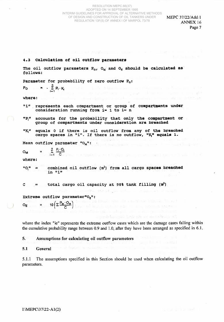
{.3 C¡lculttio¡ of oil outtlou p¡nr.t.rrthe oil outflos pararnetetrs Po, o¡r'and or should be calcr¡lated asfollows¡
Parat¡eter for probablllty of zero outllor Po:nPe =.,I,,ft.K
where:
représents each conpartuent, or group of conparl:uents turd¡rconsideration running fro¡¡ i= 1 to i= n
accounts for the probablllty that only the corqlartnant orgroup of coupartnents under consideration are breacbrd
equals o ff there is oil outf,lor fro¡¡ any of, tbe brc¡chedcargo spaces ln trltr. If there is no outflow, rr\r egual¡ 1.
lfean out,flow paraneter rro'rr.
- S ft'oi-u:igl (¿
rlr
ilPll
'Iq'
o¡r
where:
|lo.Í = conbined oil outflos (¡¡¡) fron all cargo spacêt breacbedin trLr
c total cargo oil capacity at 9st tank fi}ling (d)
Extreue outflos paramete¡rrQrr o
Os ro (r E";o'q)
where the index "ie" represents the extreme outflow cases which are the damage cases falling withinthe cumulative probabilþ range between 0.9 and 1.0, after they have been arranged as specified in 6.1.
5. Assumptions for calculating oil outflow parameters
5.1 General
5.1.1 The assumptions specifîed in this Section should be used when calculating the oil outflowparameters.
I:WIEPC\37\22-Al(2)
RESOLUTION MEPC.66(37) ADOPTED ON 14 SEPTEMBER 1995
INTERIM GUIDELINES FOR APPROVAL OF ALTERNATIVE METHODS OF DESIGN AND CONSTRUCTION OF OIL TANKERS UNDER
REGULATION 13F(5) OF ANNEX I OF MARPOL 73/78

MEPC 37/zz/Add,.tANNEX 16
Page 8
5.1.2 Outflowparameters should be calculated independently for collisions and strandings and thencombined as follows:
0.4 of the oomputed value for collisions plus
0.6 of the computed value for strandings.
5.1.3 Forsûandings, independentcalculations should be done for 0 metre,2metre and 6 metre tide.The tide, however, need not be taken greater than 50Vo of the ship's maximum draught. Outflowparameters for the stranded conditions should be a weighted average calculated as follows:
0.4 for 0 m tide condition
0.5.for minus 2 m tide condition
0.1 for minus , 6 m tide condition.
5.1.4 The damage cases and the associated probability factor "P¡" for each damage case should bedetermined based on the damage density dishibution functions as specified in paragraph 5.2.
5.1.5 The following general assumptions apply for the calculation of outflow parameters:
The ship should be assumed to be loaded to the maximum assigned loadline with zerotrim and heel and with a cargo having a density allowing all cargo tanks to be filledto 98%o.
For all casei of collision damage the entire contents of all damaged cargo oil tanksshould be assumed to be spilled into the sea, unless proven otherwise.
For all stranded conditions, the ship should be assumed aground on a shelf. Assumedstranded draughts prior to tidal change should be equal to the initial intact draughts.Should the shþ trim or float free due to the outflow oil, this should be accounted for inthe calculations for the final shipyard design.
.4 In general, an inert gas overpressure of 0.05 bar gapge should be assumed.
For the calculation of oil outflow in case of stranding the principles of hydrostaticbalance should apply, and the location of damage used for calculations of hydrostaticpressure balance and related oil outflow calculations should be the lowest point in thecargo tank.
.l
.2
.J
5
I : \IVIEP C\3 7 \22 - AT (2)
RESOLUTION MEPC.66(37) ADOPTED ON 14 SEPTEMBER 1995
INTERIM GUIDELINES FOR APPROVAL OF ALTERNATIVE METHODS OF DESIGN AND CONSTRUCTION OF OIL TANKERS UNDER
REGULATION 13F(5) OF ANNEX I OF MARPOL 73/78

.6
7
8
9
MEPC 37l22l^dd.tANNEX 16
Page 9
For cargo tanks bounded by the bottom shell, unless proven otherwise, oil outflowequal to lo/o of the volume of the damaged tank should be assumed to account forinitial exchange losses and dynamic effects due to current and waves.
For breached non-cargo spaces located wholly or in part below breached cargo oiltanks, the flooded volume of these spaces at equilibrium should be assumed to contain
50% oil and 50o/o seawater by volume, unless proven otherwise.
If deemed necessary, model tests may be required to determine the influence of tidal,current and swell effects on the oil outflow performance.
For ship designs which incorporate cargo transfer systems for reducing oil outflow,calculations should be provided illushating the effectiveness of such devices. For these
calculations, damage openings consistent with the damage density distribution functions
defined in 5.2 should be assumed.
Where, for the final shipyard design referred to in 3.3. and in the special cases referred
to 4.1.3, damage stability calculations are required, the following should apply:.10
A damage stability calculation should be performed for each damage case. The
stability in the final stage of flooding should be regarded as sufficient if the
requirements of regulation 25(3) of Annex I of MARPOL 73/78 are complied with.
Should the ship fail to meet the survivability criteria as defined in regulation 25(3),
100% oil outflow from all cargo tanks should be assumed for that damage case.
5.2 Damage assumptions
5.2.1 General,Definitions
The damage assumptions for the probabilistic oil outflow analye are given in terms of damage density
distribution functions specified in subparagraphs 5.2.2 and 5.2.3. These functions are so scaled that
the total probabilþ for each damage parameter equals l00yo, i.e. the area under each curve equals 1.0.
I:\MEPC\37\22-AI(2)
RESOLUTION MEPC.66(37) ADOPTED ON 14 SEPTEMBER 1995
INTERIM GUIDELINES FOR APPROVAL OF ALTERNATIVE METHODS OF DESIGN AND CONSTRUCTION OF OIL TANKERS UNDER
REGULATION 13F(5) OF ANNEX I OF MARPOL 73/78

MEPC 37/22tfudd.tANNEX 16
Page 10
The location of a damage refers always to the centre of a damage. Damage location and extent to an
inner horizontal bottom or vertical bulkhead should be assumed to be the same as the statisticallyderived damage to the outer hull.
The location and extent of damage to compartment boundaries should be assumed to be of rectangularshape following the hull surface in the extents defined in subparagraphs 5.2.2 and 5.2.3.
The following definitions apply for the purpose of subparagraphs 5.2.2 and 5.2.3.
x = dimensionless distance from A.P. relative to the ship's length between perpendiculars
dimensionless longitudinal extent of damage relative to the ship's length between
perpendiculars
dimensionless transverse penetration extent relative to the ship's breadth
dimensionless vertical penetration extent relative to the ship's depth
dimensionless vertical distance between the baseline and the centre of the vertical extent
4relative tothe dist¿nce between baseline and deck level (normally the ship's depth)
dimensionless transverse extent of bottom damage relative to the ship's breadth
dimensionless transverse location of bottom damage relative to the ship's breadth.
v
1
zv
zl
b
bl
5.2.2 Side ðanage due to collision
Function for longitudinal location:
f.r = 1.O for O < x 3 1.0
f"frifu
forforfor
I1.95 - 84.5y6.65 - 31.5y0.35
y30.1 s0.2 r
0.
vv
0.20.3
I3
s
I : \lrdEP C\3 7\22 - Al (2)
RESOLUTION MEPC.66(37) ADOPTED ON 14 SEPTEMBER 1995
INTERIM GUIDELINES FOR APPROVAL OF ALTERNATIVE METHODS OF DESIGN AND CONSTRUCTION OF OIL TANKERS UNDER
REGULATION 13F(5) OF ANNEX I OF MARPOL 73/78

functfon for transverse penetration:
MEPC 37l2zl\dd.rANNEX 16
Page l1
o. l,0.3
o.501. O0
ÂI¡f13at6
so51
s
0.25ztSzts
¡t-úl,t = 52t¡t :s 1' 50
s+o.24x
3_= 4.5= O.5
= 24.96 - 399.2?,1- 9.44 88.82r= 0.56
1.0
for z,for O.f,or' 0.
forforfor
zt<0.25 <0.50 <
s
33
0.zrzr
00
05
f,unction for vertical e¡.tent:
f¡ = 3.83 LL.LZ" for 2,,f¡ = 0.5 for zy
function for vertical 'Iocation¡
fff
Graphs of the functions f¡rrFiEures 1 and 2.
fo, f,o, f'r. and f.5 are shown ln
3Àbl
fr,
fvf¡z
5.2.3 Eotto! darage dr¡s to.sËrandLlg
Function for longitudinal löcation:
for xofor 5
function for longitudinal extent:
13;33y for yfor O.
function for vertlcal penetration
f¡¡ = 14.5 L342, for za S
f¡l = 1.1 for 0.1 <
function for transverse extent:
0.5x
0.3v
0.1zv
I o.8
€t¡4êt¡4€¡b4
function for transverse location:
f¡5 = 1-O for o
craphs of the functions fr,, fo,Figures g and 4.
0.3b<0.9
fo' fbo and fu are shoun ln
= 4.0= O.4= LZb
12b
10.4
for bfor ofor b
I:\lNdEPC\37U2-Al(2)
RESOLUTION MEPC.66(37) ADOPTED ON 14 SEPTEMBER 1995
INTERIM GUIDELINES FOR APPROVAL OF ALTERNATIVE METHODS OF DESIGN AND CONSTRUCTION OF OIL TANKERS UNDER
REGULATION 13F(5) OF ANNEX I OF MARPOL 73/78

MEPC 37/22/AddrANNEX 16Page 12
6. Probabilistic methodology for calculating oil outflow
6.1 Damage cases
6.1.1 Using the damage probabilþ distribution functions specified in paragraph 5.2, all damage cases"n" as per paragraph 4.3 should be evaluated and placed in ascending order of oil outflow. Thecumulalive probability for all damage cases should be computed, being the running sum of probabilitiesbeginning at the minimum outflow damage case and proceeding to the rnaximum outflow dâmage case.The cumulative probability for all damage cases should be 1.0.
6.1.2 Foreach damage case the damage consequences in terms of penetrations (breaching) of cargotank boundaries should be evaluated and the related oil outflow calculated. A cargo tank should beconsidered as being breached in a damage case under consideration if the applied damage envelopereaches any part ofthe cargo tank boundaries.
6.1.3 When determining the damage cases, it should be assumed for the purpose of these calculationsthat the location, extent and penetration of damages are independent of each other.
6.2 Oil outflow calculations
6.2.1 The probabilistic oil outflow calculations may be done as outlined by the "Example for theApplication of the Interim Guidelines" given in the Appendix to these Guidelines. Other calculationprocedures may be accepted, provided they show acceptable accuracy.
6.2.2 The computer program used for the oil outflow analysis should be verified against the data foroil outflow parameters for the reference double hull designs given in section 7.
6.2.3 After the final waterline has been determined, the oil outflow from each damaged cargo tankshould be computed for each damage case under the assumptions specified in 5.1.5.
7. Reference double hull designs
Data for four reference double hull designs of 5000 tdw, 60000 tdw, 150000 tdw and 283000 tdw aresummarized in Tables 7.1 and 7.2 and are illustrated in Figures 5 - 8.
Table 7.1 contains the data for the oil outflow parameters Po* O,* and Or* to be used for the conceptapproval (shþ survivabilþ not considered). Table 7.2 contains the corresponding data to be used forthe shipyard design approval (ship survivability considered).
I:WIEPC\37\22-AI(2)
RESOLUTION MEPC.66(37) ADOPTED ON 14 SEPTEMBER 1995
INTERIM GUIDELINES FOR APPROVAL OF ALTERNATIVE METHODS OF DESIGN AND CONSTRUCTION OF OIL TANKERS UNDER
REGULATION 13F(5) OF ANNEX I OF MARPOL 73/78

MEPC 37122/Add.tANNEX 16
Page l3
lable 7.1
lable 7.2
Ref. DealgnNo.
DeadwaightDr{(r)
Oll outflow Para¡eter¡(shtp su¡rrivabíl1ty not conridercd)lrP.,, lo,,, l*
1
2
3
4
5000
60000
150000
283000
.81
.81
.79
.77
.017
.014
.ot6
. o13
.L27
.10{
.113
.085
Ref. DasignNo.
DeadueiEhtDr{(r)
o11 outflos Paranstcrg(ship survívability consldered)
P^o on OFD
1
2
3
4
5000
60000
150000.
283000
.72
.81
.?g
.77
.lt3
.o2L
.oL7
. o15
.469
.173
.12{
.098
I : \tr4EP C\3 7\22 - Al (2)
RESOLUTION MEPC.66(37) ADOPTED ON 14 SEPTEMBER 1995
INTERIM GUIDELINES FOR APPROVAL OF ALTERNATIVE METHODS OF DESIGN AND CONSTRUCTION OF OIL TANKERS UNDER
REGULATION 13F(5) OF ANNEX I OF MARPOL 73/78

MEPC 37/22/Add.rANNEX 16
Page 14
f"t
1.2
1.0
0.8
0.6
0.4
o.2
0 x0 0.1A,P.
0.2 0.3 0.4 0.5 0.6 0.7 0.8 0.9 1.0F.P
l"z14
12
10
I
6
4
2
0
0.35
v0 0.1 o.2 0.3
fsg
25
20
15
10
5
0
24.96
0.56
10 0.05 0.1 0.15 0.2 0.25 0.3
ttttt
- Longitudinal Locat¡on-tttrt
1t E5
\\
I
- Longitudinal Extent -
I
\\
\0.35
-
\\
\
lll- Transverse Penetration -trl
\ ßft
0.56\
Side Damage due to Collision:Density Distribution Functions
fs1 , fs2, fs3Fig. 1
I:\MEPC\37\22-A1,(2)
RESOLUTION MEPC.66(37) ADOPTED ON 14 SEPTEMBER 1995
INTERIM GUIDELINES FOR APPROVAL OF ALTERNATIVE METHODS OF DESIGN AND CONSTRUCTION OF OIL TANKERS UNDER
REGULATION 13F(5) OF ANNEX I OF MARPOL 73/78

MEPC 37/22/Add.tANNEX 16
Page 15
{'5\ - Vertical Extent -rtt
0.5 -
Lt
5
4
3
2
I
0 2,0 0.1 0.2 0.3 0.4 0.5 0.6 0.7 0.8 0.9 1.0
t5
3.0
2.5
2.O
1,5
1.0
0.5
0 z2
0Bâss lino
0.25 0.5 0.75 1.0
Deck level
Vertical Location
1.s0
./6",
Side Damage due to Collision:Density Distribution Functions
fsa ând fs5
Fig.2E
I:\MEPC\37\22-AI(2)
RESOLUTION MEPC.66(37) ADOPTED ON 14 SEPTEMBER 1995
INTERIM GUIDELINES FOR APPROVAL OF ALTERNATIVE METHODS OF DESIGN AND CONSTRUCTION OF OIL TANKERS UNDER
REGULATION 13F(5) OF ANNEX I OF MARPOL 73/78

MEPC 37/22IAdd.TANNEX 16Page 16
-/rrttt-
Longitudinal Location-ltrrr -/ -
-/-/
0.6 /0.2.-- Jt-
lor
3.0
2.5
2.O
1.5
1.0
0.5
0
2.6
x0A.P.
0.1 0.2 0.3 0.4 0.5 0.6 0.7 0.8 0.9 f.0F.P.
Itz
5.0
4.0
3.0
2.0
1.0
0 v0 0.1 0.2 0.9 0.4 0,5 0.6 0.7 0.8
fbg
16
14
't2
10
I6
4
2
01.1
zo.05 o.1 0.15 0.2 0.25 0.3
(.5
\Longitu
I
ttdinal Extenttt
\
0.5
III
I4.5\
\\
\
1l'Veñical Penetration.
tl\\
\1\
Bottom Damage due to Stranding:Density Distribution Functions
fbr, fnz, fng
Fig. 3
I:\MEPC\37\22-Al(2)
RESOLUTION MEPC.66(37) ADOPTED ON 14 SEPTEMBER 1995
INTERIM GUIDELINES FOR APPROVAL OF ALTERNATIVE METHODS OF DESIGN AND CONSTRUCTION OF OIL TANKERS UNDER
REGULATION 13F(5) OF ANNEX I OF MARPOL 73/78

MEPC 37122/Add.tANNEX 16
Page l7
\\
\\
ttt' Transverse Extent'
ltt\
\\ /
/\ o-4_o.4
f¡c
4,0
3.5
3.0
2.5
2.O
1.5
1.0
0.5
0
1.6
b0 0.1 0.2 0.3 0.4 0.s 0.6 0.7 0.8 0.9 1,0
t¡s
1.2
1.0
0.8
0.6
0.4
0.2
0 b1
o 0.1 0.2 0.3 0.4 0.5 0.6 0.7 0.8 0.9 1.0
ttttr-
Transverse Location
-rrttl
Bottom Damage DensityDistribution Function
f5a and fp5
Fig. 4
I:WEPC\37\22-Al(2)
RESOLUTION MEPC.66(37) ADOPTED ON 14 SEPTEMBER 1995
INTERIM GUIDELINES FOR APPROVAL OF ALTERNATIVE METHODS OF DESIGN AND CONSTRUCTION OF OIL TANKERS UNDER
REGULATION 13F(5) OF ANNEX I OF MARPOL 73/78

MEPC 37t22/Add.rANNEX 16Fage 18
øN
6Èo
A. P. F. P.
2.75m {. * *22.2m 11m 11m 11m 11m 11m 11m
L
o
l-
I
B
only in tanks marked with *
Ballast
95.00 m16.50 m8.30 m6.20 m1.10 m1.00 m
Cargo
L=B=D=T=hDB=W=
Cargo oil capacity at 98 o/" tank filling: 6 061 m3Cargo oildensity: 0.825 V m3
Reference Double Hull Design No. 1
Deadweight: 5 000 tdwFig. 5
I:\N{EPC\37\22-Al(2)
RESOLUTION MEPC.66(37) ADOPTED ON 14 SEPTEMBER 1995
INTERIM GUIDELINES FOR APPROVAL OF ALTERNATIVE METHODS OF DESIGN AND CONSTRUCTION OF OIL TANKERS UNDER
REGULATION 13F(5) OF ANNEX I OF MARPOL 73/78

MEPC 37122/Add.tANNEX 16
Page 19
A.PI
F. P.
8.1m 25m 25m 25m 25m 25m 25m 1 0,l,
35.4mL
Õ
F
I
B
ffin Battast Cargo
L = 203.50 mB = 36.00 mD = 18.00 mT = 13.50 mhDB = 2.00 mw = 2.00m
Cargo oil capacity at 98 o/o tank filling: 70 175 m3
Cargo oildensity: 0.855 V m3
Fig. 6Reference Double Hull Design No. 2Deadweight: 60 000 tdwI
abó
I:MEPC\37\22-Al(2)
RESOLUTION MEPC.66(37) ADOPTED ON 14 SEPTEMBER 1995
INTERIM GUIDELINES FOR APPROVAL OF ALTERNATIVE METHODS OF DESIGN AND CONSTRUCTION OF OIL TANKERS UNDER
REGULATION 13F(5) OF ANNEX I OF MARPOL 73/78

MEPC 37/22tÀdd.tANNEX 16Page20
sõÈ
,i
A. P, F. P.
I
7.5 33m 33m 33m 33m 33m 33m 3
I
I
m
45.5mL
o
I
B
ffi{ Battast Cargo
L
B
D
Thoew
= 264.00 m= 48.00 m= 24.OO m= 16.80 m= 2.32 m= 2.00 m
Cargo oil capacity at 98 % tank lilling:Cargo oil density:
'175 439 m30.855 V m3
Reference Double Hull Design No. 3Deadweight: 150 000 tdw
Fig.7
I:\MEPC\37U2-Al(2)
RESOLUTION MEPC.66(37) ADOPTED ON 14 SEPTEMBER 1995
INTERIM GUIDELINES FOR APPROVAL OF ALTERNATIVE METHODS OF DESIGN AND CONSTRUCTION OF OIL TANKERS UNDER
REGULATION 13F(5) OF ANNEX I OF MARPOL 73/78

MEPC 37t22tAdd.rANNEX 16
Page2l
,-)'<:1-f
A.P F. P.
I
rJ 5.5m
50.5m 50m 50m 1
L
b
ô
B
Ballast
318.00 m57.00 m31.00 m22.04 m
2.00 m4.00 m
18.00 m
Cargo
LBD
ThoeW
b
Cargo oil capacity at 98 % tank filling: 330 994 mgCargo oil density: 0.855 Vm3
Reference Double Hull Design No. 4Deadweight: 2Bg 000 tdw
Fig. B
õàfô
I:\I\4EPC\37V2^At(2)
RESOLUTION MEPC.66(37) ADOPTED ON 14 SEPTEMBER 1995
INTERIM GUIDELINES FOR APPROVAL OF ALTERNATIVE METHODS OF DESIGN AND CONSTRUCTION OF OIL TANKERS UNDER
REGULATION 13F(5) OF ANNEX I OF MARPOL 73/78

MEPC 37I22IAdd.IANNEX 16
Page22
APPENDIX
Example for the Application of therf lnterim Guidelines tt
1. General
The application of the Interim Guidelines, hereunder refered to as Guidelines, is shown in the
following worked example illustrating the calculation procedure of the oil outflow parameters for a
tank barge. For presentation purposes, a simplifred hull form and level of compartmentation have been
assumed. The procedures described herein are readily adaptable as a computer application, which willbe necessary as more complicated arrangements are evaluated. This example is evaluated in accordance
with the requirements for "concept approval". Additional requirements for a shipyard design approvalare noted where applicable.
An application of the Guidelines will typically follow these seven basic steps:
1) Vessel design: ln accordance with paragraph 3.1 of the Guidelines, the vessel is
designed to meet all applicable regulations of Annex I of MARPOL 73178.
Establishing of the full load condition: In accordance with paragraph 5.1.5 of the Guidelines,a full load condition is developed.
2)
3) Assembling of the damage cases: By applying the damage density distribution functionsprovided in the Guidelines, determine each unique grouping of damaged compartments and the
probability associated with that damage condition. Independent sets of damage cases are
derived for side (collision) and bottom (stranding) damage.
4) Computation of the equitibrium condition for each damage case: Compute the finalequilibrium condition for all side and bottom damage conditions. This step is only requiredfor the final shipyard design, in accordance with paragraph 5.1.5.10 of the Guidelines.
Computation of the oil outflow for each damage case: Calculate the oil outflow for each
damage case. Separate calculations are done for side damage, and for bottom damage at the0,0 m, 2,0 m and 6,0 m tide conditions. For side damage, all oil is assumed to escape fromdamaged tanks. For bottom damage, a hydrostatic balance method is applied. For the finalshipyard design, survivability is evaluated in accordance with the requirements of regulation25(3) of Annex I of MARPOL 73/78.
Computation of the oil outflow parameters: The cumulative probability of occurrence ofeach level of oil outflow is developed. This is done for the side damage and for each bottomdamage tide condition. The associated oil outflow parameters are then computed. The bottomdamage tidal parameters are combined in accordance with paragraph 5.1.3, and the side and
bottom damage parameters are then combined in accordance with paragraph 5.1.2, of theGuidelines.
5)
6)
I : \lvf EP C\3 7 \22 - At (2)
RESOLUTION MEPC.66(37) ADOPTED ON 14 SEPTEMBER 1995
INTERIM GUIDELINES FOR APPROVAL OF ALTERNATIVE METHODS OF DESIGN AND CONSTRUCTION OF OIL TANKERS UNDER
REGULATION 13F(5) OF ANNEX I OF MARPOL 73/78

7)
MEPC 37/22lAdd.tANNEX 16
Page23
Computation of the Pollution Prevention Index "8": The new design has satisfactory
characteristics if "E1' as defined in paragraph 4.2 of the Guidelines is greater than or equal
to 1,0.
2. Analysis procedure
The basic steps Nos. I through 6 are described in this Section
2.1 Step l: Vessel design
The arrangement and dimensions of the example barge are as shown in Figure Al. (Barge
Arrangement). For clarity purposes, a simple arrangement has been selected which does not meet all
MARPOL 73/78 requirements. However, for actual designs submitted for approval as an alternative
to double hull, the vessel must meet all applicable regulations of Annex I of MARPOL 73178.
2,2 Step 2: Establishing of the full load condition
An intact load condition shall be developed with the vessel at its maximum assigned loadline with zero
tim and heel. Departure quantities of constants and consumables (fuel oil, diesel oil, fresh water, lube
oil, etc.) should be assumed. Capacities of cargo oil tanks should be based on actual permeability's forthese compartments. All cargo oil tanks shall be assumed to be filled to 98Yo of their capacities. Allcargo oil shall be taken at a homogenous density.
For this example, it is assumed that the permeability of the cargo oil tanks is 0,99 and 0,95 for the
double bottom/wing tank ballast spaces. The 100% capacity of the cargo oil tanks COI and CO2 is:
cot:co?:Total:
Cargo tank capacity at 98 Yo filling: C = 0,98 ' 38491 = 37721 m3 '
For this barge, for simplicity reasons, zero weight for the constants and consumables has been assumed.
At the 9,0 m assigned load line the following values for the cargo oil mass TV and density pc are
obtained:
m3m3;p.
28 868623
49
9
38 I
W : displacement - light barge weight :33 949 tP. = 33 949 t I C : 0,90 tJ mr.
2.3 Step 3: Assembling of the damage cases
In this step the damage cases have to be developed. This involves applying the probability density
distributions functions for side damage (Figures I and 2) and the probability density distribution
functions for bottom damage (Figures 3 and 4). Each unique grouping of damaged compartments is
determined together with its associated probability. The sum of the probabilities should equal 1,0 for
both the side and the bottom damage evaluations.
There are different methods available for developing the compartment groupings and probabilities, each
of which should converge on the same results.
I:\IVIEPC\37U2-Ar(2)
RESOLUTION MEPC.66(37) ADOPTED ON 14 SEPTEMBER 1995
INTERIM GUIDELINES FOR APPROVAL OF ALTERNATIVE METHODS OF DESIGN AND CONSTRUCTION OF OIL TANKERS UNDER
REGULATION 13F(5) OF ANNEX I OF MARPOL 73/78

MEPC 37tz2t\dd.tANNEX 16Page24
In this example, the compartment groupings and the use of the probability density functions is shownby a "step-wise" evaluation method. This method involves stepping through each damage location andextent at a sufficiently fine increment. For instance, it is assumed (for the side damage) to step throughthe functions as follows: longitudinal location: 100 steps, longitudinal extent: 100 steps, transversepenetration: l00.,steps, vertical location: l0 steps, and vertical extent: 100 steps. You will thenbe developing 10'y damage incidents. The probability of each step is equal to the area under theprobability density distribution curve over that increment. The probability for each damage incidentis the product of the probabilities of the five functions. There are many redundant incidents whichdamage identical compartments. These are combined by summing their probabilities. For a typicaldouble hull tanker, the 107 damage incidents reduce down to 100 to 400 unique groupings ofcompartments.
2.3.1 Side damage evaluation
The damage density distribution functions provide independent statistics for location, length, andpenetration. For side damage, the probability of a given damage longitudinal location, longitudinalextent, transverse penetration, vertical location and vertical extent is the product of the probabilitiesof these five damage characteristics.
To maintain the example ata manageable size, fairly coarse increments have been assumed:
Longitudinal location at l0 steps: :Longitudinal extent at 3 steps: =Transverse penetration at 6 steps: =
L/10 : 0,10L per step0,3L/3 = 0,10L per step0,38.16 : 0,058 per step.
To further simplify the evaluation, each damage is assumed to extend vertically without limit.Therefore, the probability of vertical location and vertical extent are taken as 1,0 for each damage case.This is a reasonable assumption as the double bottom height is only l}Yo of the depth. Taking the areaunder the density distribution function for vertical location up to O,lD (see Figure 2, function fs5)yields a value of 0,005. This means that the probability of the centre of damage location falling withinthe double bottom region is l/200.
Figure A2 (Side Damage Definition) shows the steps for longitudinal location, longitudinal extent andtransverse penetration in relation to the barge. Table Al (Increments for Step-wise Side DamageEvaluation) gives the range for each step, the mean or average value over the step, and the probabilityof occurrence of that particular step. For instance, 21 covêrs the range of transverse penetrationbeginning atthe side shell and extending inboard 5%of the breadth. The average penetration is 0,0258or 2,5%o of the breadth. The probability of occurrence is the likelihood that the penetration will fallwithin the range of 0o/o - 5%o of the breadth. The probability equals 0,749, which is the area under thedensity distribution function for transverse penetration (Figure I function fs3) between 0,08 and 0,058.The area under each probability density function is 1,0, and therefore the sum of the probabilities forall increments for each function is I,0.
A total of ten longitudinal locations, three longitudinal extents and six transverse penetrations will beevaluated. All combinations of damages must be considered for a total of (10)(3)(6): 180 separateincidents. The damaged compartments are found by overlaying each combination of location/extenlpenetration onto the barge. These damage boundaries defure a rectangular box. Any compartmentwhich extends into this damage zone is considered damaged. Each of the 180 incidents results indamage to one or more compartments. Incidents with identical damaged compartments are collectedinto a single damage case by summing the probabilities of the individual damage incidents.
I:\MEPC\37\22-At(2)
RESOLUTION MEPC.66(37) ADOPTED ON 14 SEPTEMBER 1995
INTERIM GUIDELINES FOR APPROVAL OF ALTERNATIVE METHODS OF DESIGN AND CONSTRUCTION OF OIL TANKERS UNDER
REGULATION 13F(5) OF ANNEX I OF MARPOL 73/78

MEPC 37l22lAdd.rANNEX 16
Page25
Let us begin at the aft end of the barge and proceed forward. The first damage location X 1 is centred
0,05L forward of the transom. The frrst damage extent Y1 has an average length of 0,05L. The average
value for the first transverse penetration Zl is 0,0258. The resulting damage box lies entirely withinthe WBI comparhnent and therefore damagès that compartment only. The probability of this incident
is:
pl I I (xlY tzt): (0,1000x0,7725)(0,7490) : 0,05786
If we step through the hansverse penefations 22 through 26, we frnd that only the WB I compartment
is darnaged for each of these cases. The probãbilities for these cases are 0,01074, 0,00216, 0,00216,
0,00216, 0,00216, and 0,00216 respectively. The combined probability for the six cases at longitudinaldamage location X1 is:
Pttt-O (XJ(;6) = 0,05786 + 0,01074 + 0,00216 +0,00216 + 0,00216 + 0,00216:0,07725
Next, we move to damage extent Y2. The damage boxX1Y2Z1 once again falls within the WBIcompartment. Likewise, transverse plnetrations Z2 through 26 fall within this compartment. We
compute the probability for these cases and find thatP 121-6 (XlYZZl6) : 0,01925.
Similarly, the damage boxes defrned by Xf 321_6 lie within the WBI compartment and have acombined probability Pt ¡ t-e (xtY 34-6) : 0,00350.
We now move to the next longitudinal location, X2. With longitudinal extent Y1, the damage stays
within the WBI compartment. The combined probability is P21 ç6(X2Y(l-6) = 0,07725.
The forward bound of the damage boxX2Y2Z1 extends forward of the transverse bulkhead located
20,0 m from the transom, damaging compartments both fore and aft of this bulkhead. Transverse
penetration 21 extends to a point just outboard of the longitudinal bulkhead. Therefore, this
combination dámages both the rü81 and WB2S compartments. The probability isP221(X2Y2Z) =0,01442.
We find that the damage box X2Y2Z2 extends inboard of the longitudinal bulkhead, damaging
comparünents WBl, WB2S and CO-I.11,õargo oil tank has been damaged and oil outflow will occur.
Similarly, damage penetrations 23 through 26 result in breaching of the three compartments. The
combined probability for these five incidents is:
Pzzz-ø (xzY2Z2-6) = 0,00268 + 0,00054 + 0,00054 + 0,00054 + 0,00054 : 0,00483
By stepping through the barge for all 180 incidents and combining unique damage compartment
groupings, we obtain the compartrnent grouping and probability values shown in Table 42. (Probability
Values for Side Damage) Each compartment group represents a unique set of compartments. The
associated probability is the probability that each particular group of compartments will be damaged
in a collision which breaches the hull. For instance, the probability of damaging the WBI compartment
is0,17725. This means there is approximately a 17,7%o likelihood that only this compartment will be
damaged. Likewise, the probability of concurrently damaging the WBI and WB2S compartments is
0,03408 or about 3,4yo. Note that the cumulative probability of occurrence for all groups equals 1,0.
I : \lvl EP C\3 7 \22 - AT (2)
RESOLUTION MEPC.66(37) ADOPTED ON 14 SEPTEMBER 1995
INTERIM GUIDELINES FOR APPROVAL OF ALTERNATIVE METHODS OF DESIGN AND CONSTRUCTION OF OIL TANKERS UNDER
REGULATION 13F(5) OF ANNEX I OF MARPOL 73/78
MEPC 37/22/Add.rANNEX 16Page26
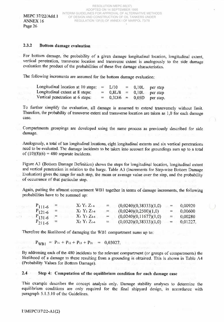
2.3.2 Bottom damage evaluation
For bottom damage, the probability of a given damage longitudinal location, longitudinal extent,vertical penetration, transverse location and transverse extent is analogously to the side damageevaluation the product of the probabilities of these fîve damage characteristics.
The following increments are assumed for the bottom damage evaluation:
Longitudinal location at 10 stepsLongitudinal extent at I steps:Verticai penetration at 6 steps:
LllD =0,8Ll8 =0,3D/6 =
0,10L0,10L0,05D
per stepper stepper step.
To further simplify the evaluation, all damage is assumed to extend transversely without limit.Therefore, the probability of tansverse extent and transverse location are taken as 1,0 for each damagecase.
Compartments groupings are developed using the same process as previously described for sidedamage.
Analogously, a total of ten longitudinal locations, eight longitudinal extents and six vertical penetrationsneed to be evaluated. The damage incidents to be taken into account for groundings sum up to a totalof (10)(8)(6) = 480 separate incidents.
Figure A3 (Bottom Damage Definition) shows the steps for longitudinal location, longitudinal extentand vertical penetration in relation to the barge. Table A3 (Increments for Step-wise Bottom DamageEvaluation) gives the range for each step, the mean or average value over the step, and the probabilityof occurrence of that particular step.
Again, putting the aftmost compartment WBI together in terms of damage increments, the followingprobabilities have to be summed up:
D' I I l-6D'12l-6D' l3l -6D'2ll-6
XtYt Zt-a
Xt Yz Zt-ø
Xt Yz Zt-o
Xz Yr Zt-o
(0,0240x0,38333X1,0)(0,0240x0,2500x1,0)(0,0240x0,t L 67 7)(1,0)(0,0320x0,38333X1,0)
: 0,00920: 0,00600: 0,00280= 0,01227
Therefore'the likelihood of damaging the tWBl compartment sums up to:
PWS1: Ptr*Prz*Pr¡*Pzr : 0,03027
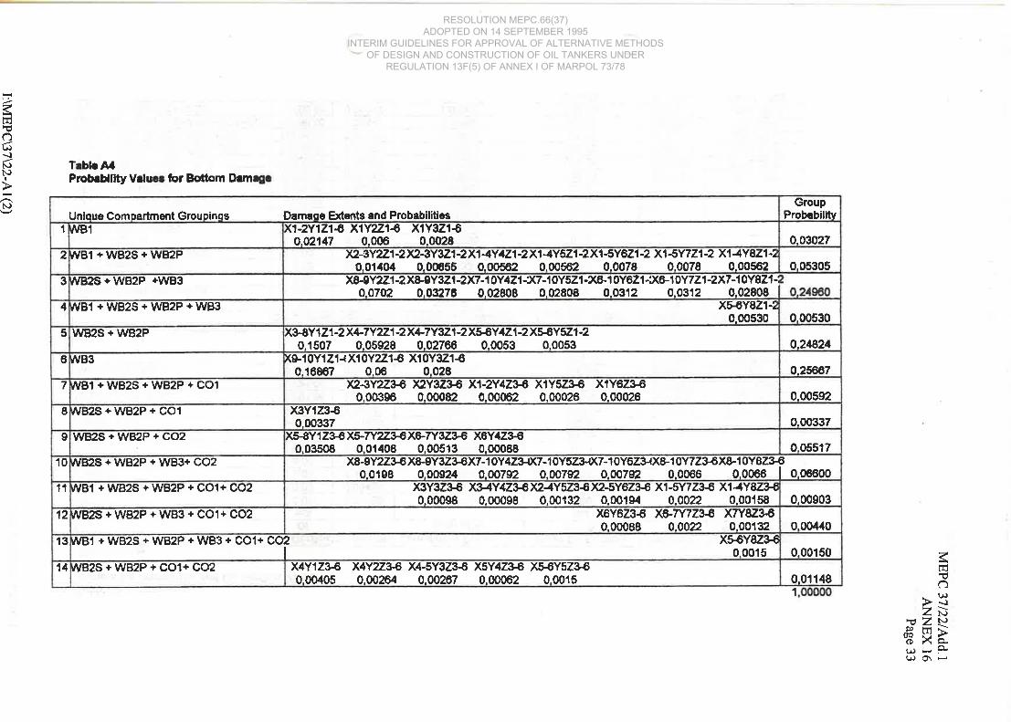
By addressing each of the 480 incidents to the relevant compartment (or groups of compartments) thelikelihood of a damage to these resulting from a grounding is obtained. This is shown in Table A4(Probability Values for Bottom Damage).
2.4 ' Step 4: Computation of the equilibrium condition for each damage case
This example describes the concept analysis only. Damage stability analyses to determine theequilibrium conditions are only required for the final shipyard design, in accordance withparagraph 5.1.5.10 of the Guidelines.
I:WIEPC\37\22-Ar(2)
RESOLUTION MEPC.66(37) ADOPTED ON 14 SEPTEMBER 1995
INTERIM GUIDELINES FOR APPROVAL OF ALTERNATIVE METHODS OF DESIGN AND CONSTRUCTION OF OIL TANKERS UNDER
REGULATION 13F(5) OF ANNEX I OF MARPOL 73/78

MEPC 37/22lfudd.lANNEX 16
Page27
2.5 Step 5: Computation of the oil outflow for each damage case
In this step the oil outflow associated with each of the compartment groupings is calculated for side
and bottom damage as outlined below.
2.5.1 Side damage evaluation
For side damage, 100% of the oil in a damaged cargo oil tank is assumed to outflow into the sea. Ifwe review the eleven compartment groupings for side damage, we find that oil tank damage occurs
in three combinations: COI only, CO2 only, and concurrent damage to COI and CO2. The oil outflowfor these tanks is as follows:
COI (98% full volume) :CO2 (98% full volume) =col + coz (98% full volume) :
zc c
9 430 m3
28 2gl m3
37 721 m3
2,5.2 Bottom damage evaluation
For bottom damage, a pressure balance calculation must be carried out. The vessel is assumed to
remain sûanded on a shelf at its original intact draft. For the concept analysis, zero trim and zero heel
are assumed. An inert gas overpressure of 0,05 bar gauge is assumed in accordance with paragraph
5.1.5.4 of the Guidelines. The double bottom spaces located below the cargo oil tanks "capture" some
portion of the oil outflow. In accordance with paragraph 5.1.5.7 of the Guidelines, the flooded volume
of such spaces should be assumed to contain 50% oil and 50o/o seawater by volume at equilibrium.When calculating the oil volume captured in these spaces, no assumptions are made on how the oil and
seawater is distributed in these spaces.
The calculations are generally caried out for three tidal conditions: 0,0 meters tide, with a 2,0 meter
tidal drop, and with a 6,0 meter tidal drop. In accordance with paragraph 5.1.3 of the Guidelines, the
tidal drop need not be taken greater than 50%o of the ship's maximum draft. For this example, the
appropriate tidal conditions are therefore 0,0 meters, 2,0 meters and 4,5 meters.
The actual oil volume lost from a cargo tank is calculated for each of the three tidal conditions
assuming hydrostatic balance as follows:
g+lQO .O,SÞap:r,
where
zc
Pco
aoz-
S
zs
P5
= height of remaining oil in the damaged tank (m): cargo oil density (0,9 t/m3)= gravitational acceleration (9,81 m/sz)= set pressure of cargo tank pressure/vacuum valves (0,05 bar g)
= external sea water head above innerbottom [m]: T-2:7,00m: sea water density (1,025 t/m3)
I:\MEPC\37U2-AI(2)
RESOLUTION MEPC.66(37) ADOPTED ON 14 SEPTEMBER 1995
INTERIM GUIDELINES FOR APPROVAL OF ALTERNATIVE METHODS OF DESIGN AND CONSTRUCTION OF OIL TANKERS UNDER
REGULATION 13F(5) OF ANNEX I OF MARPOL 73/78

MEPC 37/22tfudd.rANNEX 16Page28
See also Figure 44.
From the above equation one obtains for the height of remainin g oil z"for the zero-tide condition:
z":7r40 m.
Thus, the height of lost oil h¡ = 0,98 . h" - z. is:
h1: 17,64 - 7,40 = 10,24 m.
The volume of lost oil V¡ of cargo tank COI is:
Y1: 10,24 ' 36 ' 15 ' 0,99 :5 474 m3.
In this case the total volumo V*o of oil and water in the waterballast tanks is:
V*o = 2 [20 . 2 * zwo. 2] 60. 0,9J = 6 202 m3
where:
z*o:0,5 (2" + z.) = 7,20 m.
:
If one assumes that 50Yp of Vwo is occupied by captured oil, one obtains for the total oil outflowVoutflow of cargo tank COI:
Voutflow : Vl - 0,5 . V*o = 2 373 m3.
The oil outflow of cargo tank CO2 is:'
Vourflow : 10,24' 36' 45 . 0,gg- 0,5 . 6 202 = 13 322 m3
and the total oil outflow of cargo tanks COI and CO2 is:
Voutflow =10,24 '36'60 '0,99 - 0,5. 6202: 18 796 m3.
I:WIEPC\37\22-Ar(2)
RESOLUTION MEPC.66(37) ADOPTED ON 14 SEPTEMBER 1995
INTERIM GUIDELINES FOR APPROVAL OF ALTERNATIVE METHODS OF DESIGN AND CONSTRUCTION OF OIL TANKERS UNDER
REGULATION 13F(5) OF ANNEX I OF MARPOL 73/78

MEPC 37/22tAdd.lANNEX 16
Page29
Step-wise application of the damage extents and assumed increments results in fourteen compartmentgroupings for bottom damage. Oil tank and double bottom damage occurs in three combinations. Theoil outflows for these tanks at 0,0 meter, 2,0 m and 4,5 m tide are summarized in the table below:
Tank combination Oil outflow 1m3l at
0,0mtide I z,gmtide I ¿,smtide
wB2S+WB2P+COlwB2S+WB2P+CO2v/B2S+WB2P+COl +CO2
2 373
13 322
r8 796
3 832
17 210
23 898
5 658
22 081
30 292
2.6 Step 6: Computation of the oil outflow parameters
ln this step the oil outflow parameters are computed in accordance with paragraph 4.3 of theGuidelines. To facilitate calculation of these parameters, place the damage groupings in a table inascending order as a function of oil outflow. A running sum of probabilities is computed, beginningat the minimum outflow damage case and proceeding to the maximum outflow damage case. TablesA5 and A6(Cumulative Probabiliry and Oil Outflow Values) contains the outflow values for the sidedamage and bottom damage for the three-tide conditions.
Probability of zero outflow P6: This parameter equals the cumulative probability for all damage cases
for which there is no oil outflow. From Table 45, we see that the probability of zero outflow for theside damage condition is 0,83798, and the probability of zero outflow for the bottom damage (0,0meter tide) condition is 0,84313.
Mean outflow parameter Or: This is the weighted average of all cases, and is obtained by summingthe products of each damage case probability and the computed outflow for that damage case.
Extreme outflow parameter Or: This represents the weighted average of the damage cases fallingwithin the cumulative probability range between 0,9 and 1,0. It equals the sum of the products of eachdamage case probability with a cumulative probability between 0,90 and 1,0 and its corresponding oiloutflow, with the result multiplied by 10.
For this example, the computed outflow values are as shown in Tables A5 and 46. In accordance withparagraph 5.1.3 of the Guidelines, the bottom damage outflow parameters for the 0,0,2,0 and 4,5metertides are combined in a ratio of 0,4 : 0,5 : 0,1 respectively. In accordance with paragraph 5.1.2,the collision (side damage) and stranding (bottom damage) parameters are then combined in a ratio of0,4 : 0,6 respectively. Table A7 (Summary of Oil Outflow Parameters) the oil outflow parameters P6,O¡1 and 06 for the example tank barge are listed.
I:\MEPC\37\22-Al(2)
RESOLUTION MEPC.66(37) ADOPTED ON 14 SEPTEMBER 1995
INTERIM GUIDELINES FOR APPROVAL OF ALTERNATIVE METHODS OF DESIGN AND CONSTRUCTION OF OIL TANKERS UNDER
REGULATION 13F(5) OF ANNEX I OF MARPOL 73/78

MEPC 37t22/Add.rANNEX 16
Page 30
Table A1Increments for Step-wiseSide Damage Evaluation
Lort Location 1 Ll
p = 0,lL)
= 0,05 B)
1
1,0000
1,0000
range of incrementsminimum naximun midpoint probabÍlit
X1 0,01 0,1L 0.051 0,1000x2 0.11 0,21 0.151 0,1000x3 0.2L 0,31 0,251 0,1000x4 0,31 0,41 0,351 0,1000X5 0,41 0.51 0,451 0,1000X6 0,51 0,6L 0,551 0.1000xt 0,61 0,71 0,651 0,f 000X8 0.71 0,81 0.751 0,1000X9 0,81 0,9L 0.851 0,1000x10 0,91 I,01 0,951 0,1000
range of extentsminimum maximun averaoe orobabilitv
Y1 0,01 0,1L 0,05L 0.7725Y2 0.11 0,21 0,1 5L 0,1925Y3 0.2L 0,31 0.251 0,0350
range of penetrationminimrrm maximun averaqe probability
21 0.08 0,058 0.0258 0,749022 0,058 0,108 0,0758 0,1390z3 0,108 0.158 0,1258 0.028024 0,158 0,208 0,t7sB 0.0280z5 0.208 0,258 0.2258 0,028026 0.258 0.308 0.2758 0,0280
I:WIEPC\37\22-Al(2)
RESOLUTION MEPC.66(37) ADOPTED ON 14 SEPTEMBER 1995
INTERIM GUIDELINES FOR APPROVAL OF ALTERNATIVE METHODS OF DESIGN AND CONSTRUCTION OF OIL TANKERS UNDER
REGULATION 13F(5) OF ANNEX I OF MARPOL 73/78

Tablo A2
7frlrúot,\ìl.JN)I
l.J
for Sidc
0.17725
0.01939
0.02598
0.00088
0.03,t08
0.01142
GroupPmbabilitv
03Tr25
0.03408
0.01054
0,11532
K5Y1Z24)(5Y2z2-A<6Y172-û<6Y2f,2€f.6Y372-$<T(122€,Y;|\12728o,o1g39 o,oo{83 0,01939 0,00483 0,00088 0,01939 0,004ælKw3z2-o(8Y1Z26
I
0.0008E 0.01939 I
0,09381
x8Y2Z1 XEY3ZI X9Y2Z1 X9Y3ZÍ0.AU12 0.00262 0.0f¡l¡t2 0.00262
K8y2z2-o(8y372-6><gY2Z24'li9Y372-60.00,183 0.00088 0.00463 0.0m8E
x9y1 21 -o(1 0Y 121 -X10Y221 -Xl 0Y321 €0.07725 A.07725 0.01925 0.00350
(2Y2Z2ü2Y372-8X3Y27240.00¿163 0.000E8 0.0il83x3Y1Z1 X1Y1Z',l X1Y2Z1 X1Y3Z1 Y,5Y1Z1 X5Y2Z1 X5Y3Z10,05788 0,05788 A,OIU2 o,OO282 0.05788 0,01112 o,O02E2x8Y1Z1 X6Y2Z1 X6Y3Zí XT/1ZI XTQZI X'lv3Z1 X8Y1Z10.05788 0.011/.2 0.00202 0.05788 0.01,1¿f2 0.00262 0.05786
K3Y122-60.01939
x1Y1Z2ü1Y2724'l.1Y372{'li5Y3224'0,01939 0,00483 0,00088 0,00088
x3Y3Z2€0.00088
Kl Yr z1 €(1 Y2Zr €)(1 Y3Z1 &<2Y 1 21 Aa.oT725 0.01925 0.00350 0.0n25x2Y2Z1 X2Y1Z',l X3Y3Zí X}Y2Z1O.O1U2 0.00262 0.00262 0.01¡042
,vB2S + WB3
fVB2S+CO2+WB3
úvB3
y1/B2S + COl
wB2S+CO1 +CO2
WB1 +WB2S+COî +CO2
WB2S + COz
fvBt
WBl + WB2S
WBI+WB2S+COl
WBzS
01
11
6
7
E
I
Unioue Compartment Group¡nss Damage Efents and Probabilities1
2
3
1
5
7ràlno.(,Þ-¡zùrsZ\¡
fi *kt^¡-FtsO\F
1
RESOLUTION MEPC.66(37) ADOPTED ON 14 SEPTEMBER 1995
INTERIM GUIDELINES FOR APPROVAL OF ALTERNATIVE METHODS OF DESIGN AND CONSTRUCTION OF OIL TANKERS UNDER
REGULATION 13F(5) OF ANNEX I OF MARPOL 73/78

MEPC 37/22/Add.IANNEX 16Page32
Table A3lncrements for Step-wiseBottom Damage Definition
Longitudinal
Longitudi Extent
Vertical Penetration
1
1,0000
I
1,0000
srerange of incrementsminimum maximum midooint probability
X1 0,0L 0,1L 0,051 0,0240x2 0,1L 0,2L 0,151 0,0320X3 0.2L 0,31 0,251 0,0400x4 0.31 0,41 0,351 0.0480X5 0.41 0,51 0.45L 0.0560X6 0.51 0,61 0.55L 0.0800x7 0,61 0.71 0.651 0.1200x8 0,7L 0,81 0.751 0,1600X9 0,81 0.9L 0.851 0,2000x10 0.91 1.01 0,951 0.2400
range of extentsminimum maxmum averaoe orobabilitv
Y1 0,0L 0,11 0.051 0,3833Y2 0,11 0.21 0,151 0,2500Y3 0.21 0.31 0,251 0,1167Y4 0,31 0.41 0.35L 0,0500Y5 0.41 0,51 0.451 0.0500Y6 0.51 0.61 0.551 0.0500Y7 0,6L 0.71 0.651 0.0500Y8 0,71 0.81 0,751 0,0500
range of penetratlonmlntmum maximum averaoe probability
21 0,0D 0.025D 0,5575z2 0,05D 0. OD 0.075D 0.222523 0.10D 0.150 0.125D 0.0550z4 0,f 5D 0,175D 0,0550z5 0,20D 0,22sD 0.055026 0.25D 0.: ¡0D 0,275D 0.0550
I:\MEPC\37\22-Al(2)
RESOLUTION MEPC.66(37) ADOPTED ON 14 SEPTEMBER 1995
INTERIM GUIDELINES FOR APPROVAL OF ALTERNATIVE METHODS OF DESIGN AND CONSTRUCTION OF OIL TANKERS UNDER
REGULATION 13F(5) OF ANNEX I OF MARPOL 73/78
lntsu
()(,\¡N)NIÞNJ
Trbl¡AlPmb¡Hllty Vrlu¡r lor Bottorn Drm¡r
0.05517
0.00903
0.00¿140
0.00150
0.0f 148
GroupProbabilltv
o.03027
0.05305
0.00530
o.21824
0.25667
0.00592
0.00337x3Yt23€0.00æ7
xæY1Z X5-7Y2Z36X&7Y3Z3€ X6Y4Z3€0.03508 0.01¿+08 0.00513 0.00088
x8-9Y223€ X&9Y323€X7-1 0Y423{(7-r 0Y523{(7-1 0Y623{X&1 0Y7236X8-1 0Y823'€0.0198 0.00û24 o.oo792 0.oa7n. o.oo792 0.006ô 0.0066 I o,oeooo
x3Y3Z3€ XUY4Z )(¿4Y5236)(2-5Y6Z3€ X1-5Y723€ X14Y82340.00098 0.00098 0.00132 0.00194 0.00n. 0.00158
x6Y6Z3€ X6-7Y7z.æ X7YBZ0.00088 0.00n. 0,00132
x4Y2Z36 X4-5y323€ X5y4Z3€ X56Y5Z3Æ0,00264 0.00267 0.00062 0.0015
x4Y12360.00405
K1-2Y121ô X',tYzZ1ôo.a2147 0.006
x1Y3Z1€0,0028
X2-3Y221-2}<2-3Y3Z1-2X14Y121-2X14Y521-2X1-5Y621-2 X1-5YVZ1-2 X14YEZ1-20.01¡10¿1 0.0æ55 0.00582 0.00562 0,0078 0,0078 0,00562
Y&gy2z1-2X&'9Y3Z1-2X7-10Y421-X7-'t0Y5Z1-X&10Yô21-X&l0Y7Z1-2X7-10YSZ1-io.a7s2 0.03276 0.02808 0.02808 0.0312 0.0312 0.02808 I
xæY821-20,00530
xæy121-2x+7y221-2X+7Y321¿X56y421-2Xff Y5Z1-20.1507 0.05928 0.0127æ 0.0053 0.0053
K9-1 0Y1 21'{ X10Y2Z1ô X10Y32160,16887 0,00 0,028
xz-gYzu.ß )eY3Z3ó X1-2Y4Z XIY5Z3€ X1Y6Z3€0,00396 0,00082 0,00062 0.00026 0,00026
JVB1+WB2S+WBzP+CO1
,VB2S+WB2p+CO1
wB2S+WB2P+CO2
/vBzS + WB2P + WB3+ COz
^/Bi + WB2S + WB2P + CO1+ COz
/VB2S + WB2P + WB3 + COl+ CO2
fVBl + WB2S + WB2P + WE¡3 + COl+ COzI
x56Y82&€0.0015
úVB2S + WB2P + CO1+ CO2
¡vB1
/VBl +WB2S+WB2P
IVB2S + WB2P +WB3
,VB1+WB2S+WB2P+WB3
WB2S + WB2P
úvB3
7
II01
11
12
13
14
Ðamaqe Efents and ProbabiliticsUnloue Comoartmeñt Grouoinos1
2
3
4
5
6
7lnFË
ô>3zù='uZ\¡
€ Hàt¡ * PrrO\Ê
1
RESOLUTION MEPC.66(37) ADOPTED ON 14 SEPTEMBER 1995
INTERIM GUIDELINES FOR APPROVAL OF ALTERNATIVE METHODS OF DESIGN AND CONSTRUCTION OF OIL TANKERS UNDER
REGULATION 13F(5) OF ANNEX I OF MARPOL 73/78

FÞ<ù 4rrJ@ Zry9)rnc)ÈX,,,.\¡o\ I'J
IQ
È-Þ'P
?FJ
()(¡)-¡l.Jl\)I
N)
Trble A5Gumul¡tlvr Probrb¡lty .nd O¡l Ot¡tflow Vrlur
8980
,1
331,9448
irt¡¡mr OutllowPlc' Olc' l0
m3
17ß1,20523230.83?2,
9799.9158
Plr
0.011420.0006E0.02598
Probrbllltv
0,48172
0,00
2653.98
Mcrn Oll Oqtllow
979.99
0.000.(X)0.00
Pl .ol
0.00
m3
99.39182_85
323.0833.19
0,961720.e7314
0.21133
o.83788
o.86791
o.97402r.00000
0.62665o.66073
Cumulrtlvo Prohbllttv¡um ol Pl
o.17725
o.84852
0,00088
o.019390.09381
0.03408
0.o1054
4t77250.03408
o.17725
Probrbllltv
0.41532
o.o1142
0.02598
PI
o.oo
0.00o.qt
37721.W37721.æ
2C2S1.W2ü¿91-fm
ôll O¡rtllo*otm3
0.o00.00
9430.(x}9430.00
wBl+WB2S+CO1+CO2WB2S+CO1+CO2
lomo¡rtmcnt Grouolnor
wB2S+CO2
WB1+WB2S
wB2S+CO2+W83
wB1
WB2SWB2S+WB3wB3WB1+WB2S+CO1wB2S+COl
1012.4720
2155.9012
8752,52001697.2788281.9400827.0240
Erlnmr OutllmPlr' Ol¡' l0
m3
0.oo440
0.00760
0.009030.00150
0.01147
ProbebllttvPlc
0,06600
2E.1982.70
0.00
0.000.000.00
8.00
879,25
M¡en Oll OutflowPl'ol
m3
0.000,00
14,05
735,11
169.73
215.59
0,08331
0.97360
o.03027
0.088610.336860.58646
o.85242
0.982630.984130.988531,00000
0.84905
Cumulflvc Probrbllltv¡um of Pl
0,84313
0,90760
0,00530
0.030270.05304
0.249600.25õ67
0.0551E0.066(X)
0.004400.01147
0.00903
ProbrbllltvPI
0.24825
0,005920.00337
0.00150
0.00
2373.00
ol
0.(X¡0.00
0.000.(x)
187S6.0018796.00
Oll Outlloìr
m3
0.00
2373.æ133?2..OO1332..OO187S.0018796,00
WB2P+WB2S+WB3 + COz
WB1 +WB2P+WBzS
WB2P+WB2S+CO1+Co2
W82P+WB2S+CO2
Comoertmant Orouoing¡wB1
WBl+WB2P+WB2S+WB3W82P+WB2SWB2P+WB2S+W83wB3WB1 +WB2P+WB2S+CO1WB2P+W82S+COl
WB1 +WB2P+WB2S+CO1 +CO2
WB3+WB2P+WB2S+CO 1 +CO2
WB 1 +WB2P+WB2S+WB3+CO I +CO2
2132,t2 0,1
RESOLUTION MEPC.66(37) ADOPTED ON 14 SEPTEMBER 1995
INTERIM GUIDELINES FOR APPROVAL OF ALTERNATIVE METHODS OF DESIGN AND CONSTRUCTION OF OIL TANKERS UNDER
REGULATION 13F(5) OF ANNEX I OF MARPOL 73/78

?E1:úo(,\¡I'JNI
l.J
Trblo AtCumul¡tlvc Probeblllty rnd Oll O¡¡tflowV¡lu¡
358.4700
1 1358.6000
Pþ' Oic' l0
1307.9600
2157.9894
1051.5r202741.10çß
Ertrumc Outflow
m3
0.00760
0.00150
0,011470.00440
Prob¡bilttvP¡c
0.o66üt0.00903
0.oo
105,15
0.00
35,E5
0.(X)
0.(X)
llern Oll OutllowPl. o¡
m30.000.00
n.6912.91
949.051135.6õ215.80
274.110.s8853
0.84313
0,0E8610.336860.56646
o.852420.90760
0.9E413
0,03027
0,84905
0.973600.98263
1.00000
Cumul¡tlvr Probrbllltv¡um ofPl
0.01147
o.248250.249600.25667
0,00150
0.055f I0.00337
0,03027
0.00530
0.00592
0.066000.00903
0.00440
Prob¡bllttvPI
0.00
0.000.00
0.00
00
3832-00
17210.0017210.OO23898.0023898.00
23898.00
Oll Outf,owotm30.00
3832.00
WB2P+WB2S+CO1+CO2
WB2P+WB2S+COl
WB2P+WB2S
WB3+WB2P+WB2S+CO1 +COZ
W82P+W82S+CO2
Como¡Émcnt Grouolno¡
WB2P+WB2S+WB3 + CO2WB1 +WB2P+WB2S+CO1 +CO2
wB1 +WB2P+WB2S+WB3+CO1 +COz
wB1
WB1+WB2P+WB2S+WB3C
wB2P+W82S+WB3wB3WB1 +WB2P+WB2S+CO1
1332.8480u74.4924
't678.1560
rtr.mâ Outíow
454.3800
PL'O¡c' lOm3
'14573.46002735.æ76
0,007õ0
o,oo4400.001500.00903
ProbabllltvPlc
0.06600
0.01147
45,14273.54
0.00
0.00
33,5019.07
0.00
0.(X¡0.00
M¡en Oll OutfiorvPl'ol
m30,00
1218.431457.35
133.28v7.451.00000
0.083310.088610.33686
0.843130.58el6
0,90700
0.98263
0,98853
0,849050.85242
0.97360
0,9E413
Cumulflvr Probrbllltv¡um ofPl
0,03027
0,00150
0.03027
o.24825
0,00440
0.24960
0.05518
0.01147
0.256670.00592
0.00903
0.00530
0,00337
PrcbrblllhrPI
0,05304
0,06600
30292,00
22081,00
0.000,000.000,00
30292.00
565E.0056s8.00
22081.00
30292.00
3û292.00
Oil O¡¡tflowotm3
0,000.00
WB 1 +WB2P+WB2S+WB3+CO1 +CO2
w92P+W82S+C02
WB3+WB2P+WB2S+CO1 + CO2
WB1 +WB2P+WB2S+CO1
WB2P+WB2S+WB3 + CO2
lomorrtment Grouolno¡WB1WB1 +WB2P+WB2SWBl+WB2P+WB2S+WB3CW82P+W82SwB2P+W82S+WB3WB3
WB2P+WB2S+CO1
WB1 +WB2P+WB2S+CO1 +CO2
WB2P+WB2S+CO1+CO2
?lnFË
c)- (¡)>\¡zù'ËzN€ HÈu¡-F(¡o\Ê
RESOLUTION MEPC.66(37) ADOPTED ON 14 SEPTEMBER 1995
INTERIM GUIDELINES FOR APPROVAL OF ALTERNATIVE METHODS OF DESIGN AND CONSTRUCTION OF OIL TANKERS UNDER
REGULATION 13F(5) OF ANNEX I OF MARPOL 73/78

MEPC 37/22tfudd.rANNEX 16Page 36
Table A7Summary of Oil Outflow paråmêterc
Bpttgm Damage ß00 t (500/61 1Oolol
0,0 m t¡de 2.0 m tide Combinedof 0,8431 0.8431 0,8431
l/lean Outflow m3 2133 2752 3528 2582Extreme Outflow m3 14767 18976 24249 17820
Combined Sideand Bottom Damage
(40iÀl (600/ol
Side BottomDamaoe Damaqe Combined
Probabillty of Zero Outflow P0 0,8380 0,843r 0.8411m3 1272 2582 3258
30824 17820 23021llaan Outflow Paramêter OM 0.0864xtrume Outflow Parameter OE 0.6103
I:\MEPC\37\22-At(2)
RESOLUTION MEPC.66(37) ADOPTED ON 14 SEPTEMBER 1995
INTERIM GUIDELINES FOR APPROVAL OF ALTERNATIVE METHODS OF DESIGN AND CONSTRUCTION OF OIL TANKERS UNDER
REGULATION 13F(5) OF ANNEX I OF MARPOL 73/78

MEPC 37122/Add.lANNEX 16
Page 37
B
20m 15m
36m
20m 20m
B
Midship section
45m
WB2P
W82S
Plan view
20m
Barge Particulars
L
2m,--l , 2ml..-
D
L=-100mB= 40mT
T D=-20m9m
displacemenl =- 36900 t
light barge weight = _ 2951 t
C01, C02 = -- cargo oil tanks
WB1,WB2,WB3 = water ballast tanks
Fig. A1 : Barge Arrangement
co1 co2
I:WIEPC\37\22-Al(2)
RESOLUTION MEPC.66(37) ADOPTED ON 14 SEPTEMBER 1995
INTERIM GUIDELINES FOR APPROVAL OF ALTERNATIVE METHODS OF DESIGN AND CONSTRUCTION OF OIL TANKERS UNDER
REGULATION 13F(5) OF ANNEX I OF MARPOL 73/78

MEPC 37/22/Add.tANNEX 16Page 38
I
X1I
X4I
X3I
x2I
X8I
x7
Longitudinal Damage LocationX
IX6
Ix5
IX9
I
x10
0 L
max. ex'tent
extent
Y1
Y3
d)('¿oc.9E0,c0,o.x(úE
co(ú
(¡)coac)lt)Eo(ú
dlrOod
z5-
z3--
lgng'bhd.
side shell
Longitudinal Damage Extent Transverse Damage Penetration
Fig. A2: Side Damage Definition
co2 ---- co1
0,1 L
WB2P
WB2S
-- wB1 --- - wB3 ---
0,1 L
l==riìililllli
I:MEPC\37\22-Al(2)
RESOLUTION MEPC.66(37) ADOPTED ON 14 SEPTEMBER 1995
INTERIM GUIDELINES FOR APPROVAL OF ALTERNATIVE METHODS OF DESIGN AND CONSTRUCTION OF OIL TANKERS UNDER
REGULATION 13F(5) OF ANNEX I OF MARPOL 73/78

,1, I ¿ I *f I'i I'L l'! l'l I'L I *L I "l' I
x Longitudinal Damage Location
-
I FÊ-r lYz
MEPC 37/22/Add.tANNEX 16
Page 39
Y8
botlom
Lmax. extent
extent
Yô
Y4
Y7
Y5
J
-¡õttõm
ô(Ð_
oco'p(úocoo.
fitE
c.9(E
ocoCL
_ooEo(ú
oroo-o
I
Y1
rnner
Longitudinal Damage Extent
Vertical Damage Penetration
- col
WB2P
0,1 LW92S
T=
=l
0,1 L
l==l ilil1
ililr
tilil1
Tililt
il1il
ililt
I : \l\4 EP C\3 7\22 - Al (2)
Fig.A3: Bottom Damage Definition
RESOLUTION MEPC.66(37) ADOPTED ON 14 SEPTEMBER 1995
INTERIM GUIDELINES FOR APPROVAL OF ALTERNATIVE METHODS OF DESIGN AND CONSTRUCTION OF OIL TANKERS UNDER
REGULATION 13F(5) OF ANNEX I OF MARPOL 73/78

MEPC 37/22tfudd.rANNEX 16Page 40
2m
Dhc
EC\.l
Lcot
Lcoz
Lwez
hc
36m
Wmffi
2nt
2 o/o Yapour Space
20m
50 % oiland 50 % water
oil
oilvolume lost from cargo tanks
20m
= 15,0 m
= 45,0 m
= 60,0 m
= 18,0 m
B
Fig. A4: Oil Outflow Scheme for Bottom Damage
I:WIEPC\37\22-AI(2)
* {( ¡1.
RESOLUTION MEPC.66(37) ADOPTED ON 14 SEPTEMBER 1995
INTERIM GUIDELINES FOR APPROVAL OF ALTERNATIVE METHODS OF DESIGN AND CONSTRUCTION OF OIL TANKERS UNDER
REGULATION 13F(5) OF ANNEX I OF MARPOL 73/78

RESOLUTION MEPC.66(37) ADOPTED ON 14 SEPTEMBER 1995
INTERIM GUIDELINES FOR APPROVAL OF ALTERNATIVE METHODS OF DESIGN AND CONSTRUCTION OF OIL TANKERS UNDER
REGULATION 13F(5) OF ANNEX I OF MARPOL 73/78