Embed Size (px)
Citation preview
2010 Microchip Technology Inc. DS51891A
Resistive Temperature Detector (RTD)Reference Design
Note the following details of the code protection feature on Microchip devices:
• Microchip products meet the specification contained in their particular Microchip Data Sheet.
• Microchip believes that its family of products is one of the most secure families of its kind on the market today, when used in the intended manner and under normal conditions.
• There are dishonest and possibly illegal methods used to breach the code protection feature. All of these methods, to our knowledge, require using the Microchip products in a manner outside the operating specifications contained in Microchip’s Data Sheets. Most likely, the person doing so is engaged in theft of intellectual property.
• Microchip is willing to work with the customer who is concerned about the integrity of their code.
• Neither Microchip nor any other semiconductor manufacturer can guarantee the security of their code. Code protection does not mean that we are guaranteeing the product as “unbreakable.”
Code protection is constantly evolving. We at Microchip are committed to continuously improving the code protection features of ourproducts. Attempts to break Microchip’s code protection feature may be a violation of the Digital Millennium Copyright Act. If such actsallow unauthorized access to your software or other copyrighted work, you may have a right to sue for relief under that Act.
Information contained in this publication regarding deviceapplications and the like is provided only for your convenienceand may be superseded by updates. It is your responsibility toensure that your application meets with your specifications.MICROCHIP MAKES NO REPRESENTATIONS ORWARRANTIES OF ANY KIND WHETHER EXPRESS ORIMPLIED, WRITTEN OR ORAL, STATUTORY OROTHERWISE, RELATED TO THE INFORMATION,INCLUDING BUT NOT LIMITED TO ITS CONDITION,QUALITY, PERFORMANCE, MERCHANTABILITY ORFITNESS FOR PURPOSE. Microchip disclaims all liabilityarising from this information and its use. Use of Microchipdevices in life support and/or safety applications is entirely atthe buyer’s risk, and the buyer agrees to defend, indemnify andhold harmless Microchip from any and all damages, claims,suits, or expenses resulting from such use. No licenses areconveyed, implicitly or otherwise, under any Microchipintellectual property rights.
DS51891A-page 2
Trademarks
The Microchip name and logo, the Microchip logo, dsPIC, KEELOQ, KEELOQ logo, MPLAB, PIC, PICmicro, PICSTART, PIC32 logo, rfPIC and UNI/O are registered trademarks of Microchip Technology Incorporated in the U.S.A. and other countries.
FilterLab, Hampshire, HI-TECH C, Linear Active Thermistor, MXDEV, MXLAB, SEEVAL and The Embedded Control Solutions Company are registered trademarks of Microchip Technology Incorporated in the U.S.A.
Analog-for-the-Digital Age, Application Maestro, CodeGuard, dsPICDEM, dsPICDEM.net, dsPICworks, dsSPEAK, ECAN, ECONOMONITOR, FanSense, HI-TIDE, In-Circuit Serial Programming, ICSP, Mindi, MiWi, MPASM, MPLAB Certified logo, MPLIB, MPLINK, mTouch, Omniscient Code Generation, PICC, PICC-18, PICDEM, PICDEM.net, PICkit, PICtail, REAL ICE, rfLAB, Select Mode, Total Endurance, TSHARC, UniWinDriver, WiperLock and ZENA are trademarks of Microchip Technology Incorporated in the U.S.A. and other countries.
SQTP is a service mark of Microchip Technology Incorporated in the U.S.A.
All other trademarks mentioned herein are property of their respective companies.
© 2010, Microchip Technology Incorporated, Printed in the U.S.A., All Rights Reserved.
Printed on recycled paper.
ISBN: 978-1-63276-347-1
Microchip received ISO/TS-16949:2002 certification for its worldwide
2010 Microchip Technology Inc.
headquarters, design and wafer fabrication facilities in Chandler and Tempe, Arizona; Gresham, Oregon and design centers in California and India. The Company’s quality system processes and procedures are for its PIC® MCUs and dsPIC® DSCs, KEELOQ® code hopping devices, Serial EEPROMs, microperipherals, nonvolatile memory and analog products. In addition, Microchip’s quality system for the design and manufacture of development systems is ISO 9001:2000 certified.
RTD REFERENCE DESIGN
Table of Contents
Preface ........................................................................................................................... 5Introduction............................................................................................................ 5
Document Layout .................................................................................................. 5
Conventions Used in this Guide ............................................................................ 6
Recommended Reading........................................................................................ 7
The Microchip Web Site ........................................................................................ 7
Customer Support ................................................................................................. 7
Document Revision History ................................................................................... 7
Chapter 1. Product Overview1.1 Introduction ..................................................................................................... 91.2 What is the RTD Reference Design? ............................................................. 91.3 What the RTD Reference Design kit includes ................................................ 9
Chapter 2. Installation and Operation2.1 Introduction ................................................................................................... 112.2 Features ....................................................................................................... 112.3 Getting Started ............................................................................................. 12
Appendix A. Schematic and LayoutsA.1 Introduction .................................................................................................. 17A.2 Board - Schematic ...................................................................................... 18A.3 Board - Top Silk and Pads ........................................................................... 19A.4 Board - Top Layer ........................................................................................ 19A.5 Board - Bottom Silk and Pads ...................................................................... 20A.6 Board - Bottom Layer ................................................................................... 20
Appendix B. Bill of Materials
Worldwide Sales and Service .................................................................................... 22
2010 Microchip Technology Inc. DS51891A-page 3
RTD Reference Design
NOTES:
DS51891A-page 4 2010 Microchip Technology Inc.
RTD REFERENCE DESIGN
Preface
INTRODUCTION
This chapter contains general information that will be useful to know before using the RTD Reference Design. Items discussed in this chapter include:
• Document Layout
• Conventions Used in this Guide
• Recommended Reading
• The Microchip Web Site
• Customer Support
• Document Revision History
DOCUMENT LAYOUT
This document describes how to use the RTD Reference Design as a development tool to emulate and debug firmware on a target board. The manual layout is as follows:
• Chapter 1. “Product Overview” – Important information about the RTD Reference Design.
• Chapter 2. “Installation and Operation” – This chapter includes a detailed description of each function of the demo board and instructions for how to begin using the board.
• Appendix A. “Schematic and Layouts” – Shows the schematic and layout diagrams for the RTD Reference Design.
• Appendix B. “Bill of Materials” – Lists the parts used to build the RTD Reference Design.
NOTICE TO CUSTOMERS
All documentation becomes dated, and this manual is no exception. Microchip tools and documentation are constantly evolving to meet customer needs, so some actual dialogs and/or tool descriptions may differ from those in this document. Please refer to our web site (www.microchip.com) to obtain the latest documentation available.
Documents are identified with a “DS” number. This number is located on the bottom of each page, in front of the page number. The numbering convention for the DS number is “DSXXXXXA”, where “XXXXX” is the document number and “A” is the revision level of the document.
For the most up-to-date information on development tools, see the MPLAB® IDE on-line help. Select the Help menu, and then Topics to open a list of available online help files.
2010 Microchip Technology Inc. DS51891A-page 5
RTD Reference Design
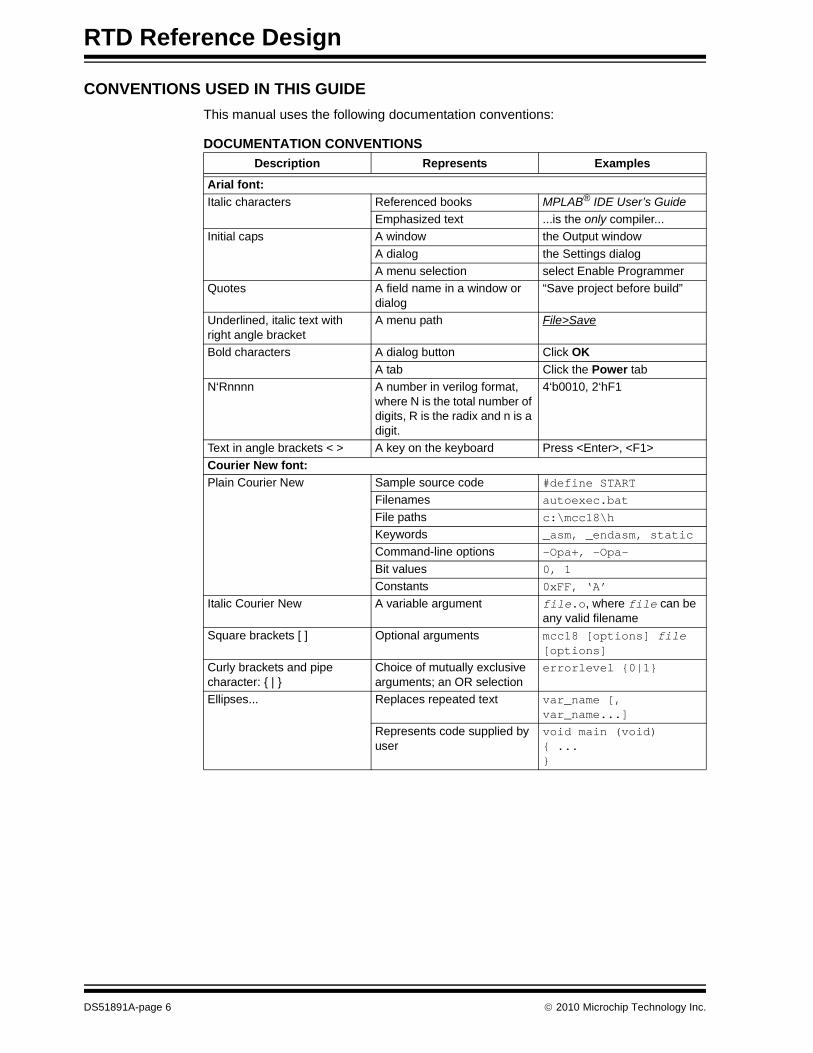
CONVENTIONS USED IN THIS GUIDE
This manual uses the following documentation conventions:
DOCUMENTATION CONVENTIONS
Description Represents Examples
Arial font:
Italic characters Referenced books MPLAB® IDE User’s Guide
Emphasized text ...is the only compiler...
Initial caps A window the Output window
A dialog the Settings dialog
A menu selection select Enable Programmer
Quotes A field name in a window or dialog
“Save project before build”
Underlined, italic text with right angle bracket
A menu path File>Save
Bold characters A dialog button Click OK
A tab Click the Power tab
N‘Rnnnn A number in verilog format, where N is the total number of digits, R is the radix and n is a digit.
4‘b0010, 2‘hF1
Text in angle brackets < > A key on the keyboard Press <Enter>, <F1>
Courier New font:
Plain Courier New Sample source code #define START
Filenames autoexec.bat
File paths c:\mcc18\h
Keywords _asm, _endasm, static
Command-line options -Opa+, -Opa-
Bit values 0, 1
Constants 0xFF, ‘A’
Italic Courier New A variable argument file.o, where file can be any valid filename
Square brackets [ ] Optional arguments mcc18 [options] file [options]
Curly brackets and pipe character: { | }
Choice of mutually exclusive arguments; an OR selection
errorlevel {0|1}
Ellipses... Replaces repeated text var_name [, var_name...]
Represents code supplied by user
void main (void){ ...}
DS51891A-page 6 2010 Microchip Technology Inc.
Preface
RECOMMENDED READING
This user's guide describes how to use the RTD Reference Design. Other useful documents are listed below. The following Microchip documents are available and recommended as supplemental reference resources.
MCP3551 Data Sheet, “Low-Power, Single-Channel 22-Bit Delta-Sigma ADCs” (DS21950)
This data sheet provides detailed information regarding the MCP3551 device.
AN1154 - “Precision RTD Instrumentation for Temperature Sensing” (DS01154)
This application note provides information on the RTD Instrumentation technique for high performance thermal management applications.
THE MICROCHIP WEB SITE
Microchip provides online support via our web site at www.microchip.com. This web site is used as a means to make files and information easily available to customers. Accessible by using your favorite Internet browser, the web site contains the following information:
• Product Support – Data sheets and errata, application notes and sample programs, design resources, user’s guides and hardware support documents, latest software releases and archived software
• General Technical Support – Frequently Asked Questions (FAQs), technical support requests, online discussion groups, Microchip consultant program member listing
• Business of Microchip – Product selector and ordering guides, latest Microchip press releases, listing of seminars and events, listings of Microchip sales offices, distributors and factory representatives
CUSTOMER SUPPORT
Users of Microchip products can receive assistance through several channels:
• Distributor or Representative
• Local Sales Office
• Field Application Engineer (FAE)
• Technical Support
Customers should contact their distributor, representative or field application engineer (FAE) for support. Local sales offices are also available to help customers. A listing of sales offices and locations is included in the back of this document.
Technical support is available through the web site at: http://support.microchip.com.
DOCUMENT REVISION HISTORY
Revision A (September 2010)
• Initial Release of this Document.
2010 Microchip Technology Inc. DS51891A-page 7

RTD Reference Design
NOTES:
DS51891A-page 8 2010 Microchip Technology Inc.
RTD REFERENCE DESIGN
Chapter 1. Product Overview
1.1 INTRODUCTION
The following name and assembly number are found on the RTD Reference Design’s Printed Circuit Board (PCB):
• 102-00115
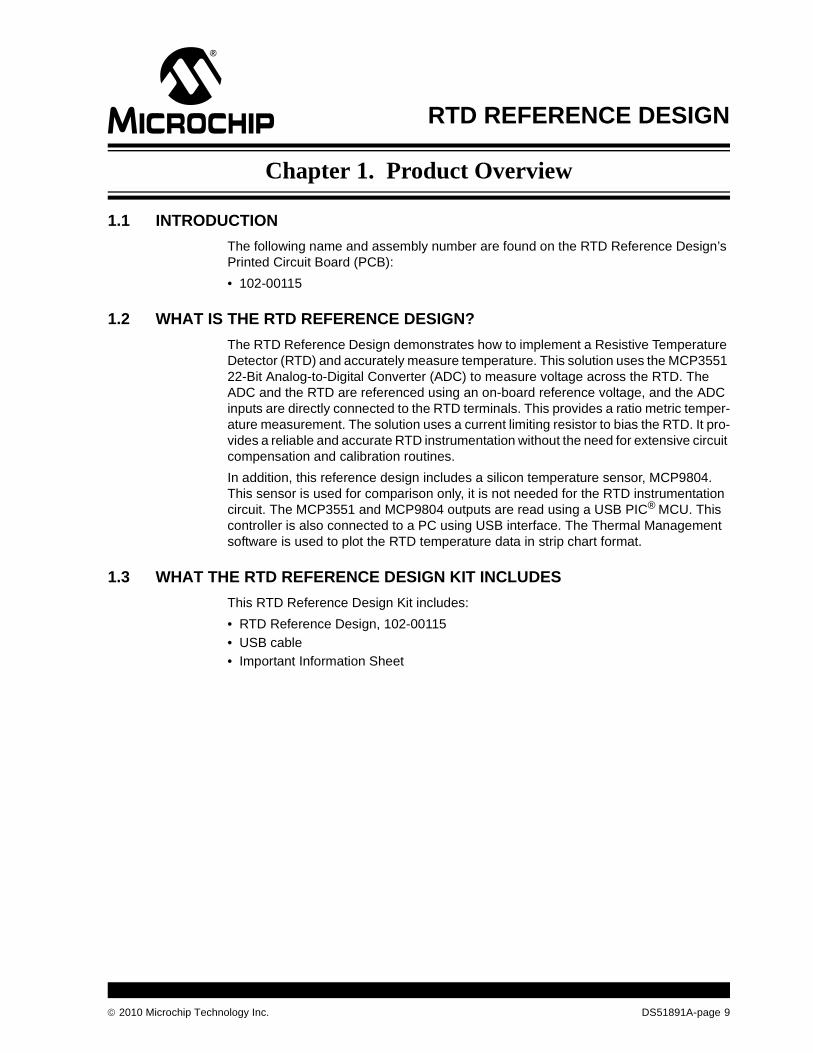
1.2 WHAT IS THE RTD REFERENCE DESIGN?
The RTD Reference Design demonstrates how to implement a Resistive Temperature Detector (RTD) and accurately measure temperature. This solution uses the MCP3551 22-Bit Analog-to-Digital Converter (ADC) to measure voltage across the RTD. The ADC and the RTD are referenced using an on-board reference voltage, and the ADC inputs are directly connected to the RTD terminals. This provides a ratio metric temper-ature measurement. The solution uses a current limiting resistor to bias the RTD. It pro-vides a reliable and accurate RTD instrumentation without the need for extensive circuit compensation and calibration routines.
In addition, this reference design includes a silicon temperature sensor, MCP9804. This sensor is used for comparison only, it is not needed for the RTD instrumentation circuit. The MCP3551 and MCP9804 outputs are read using a USB PIC® MCU. This controller is also connected to a PC using USB interface. The Thermal Management software is used to plot the RTD temperature data in strip chart format.
1.3 WHAT THE RTD REFERENCE DESIGN KIT INCLUDES
This RTD Reference Design Kit includes:
• RTD Reference Design, 102-00115
• USB cable
• Important Information Sheet
2010 Microchip Technology Inc. DS51891A-page 9
RTD Reference Design
NOTES:
DS51891A-page 10 2010 Microchip Technology Inc.
RTD REFERENCE DESIGN
Chapter 2. Installation and Operation
2.1 INTRODUCTION
The RTD Reference Design demonstrates Microchip’s solution to accurately measure temperature using a 22-bit ADC, MCP3551. This solution eliminates the need for the traditional analog instrumentation system calibration or gain and offset trimming techniques. In addition, the effect of self-heat can be minimized by limiting the RTD biasing current using a single resistor.
This reference design uses the technique described in Application Note AN1154 - “Precision RTD Instrumentation for Temperature Sensing” (DS01154). The RTD Reference Design allows users to evaluate Microchip’s solution to accurately measure temperature using an RTD. RTD resistance availability typically ranges from 100 to 5000. When biasing an RTD to measure temperature, self-heat due to power dissipation has to be considered. In order to output measurable voltage across the RTD for wide temperature range, the biasing current has to be relatively high. This causes higher power dissipation through heat and skews the temperature reading. This solution uses a ratiometric technique between the RTD resistance and the ADC resolution to achieve high accuracy throughout the entire sensor range.
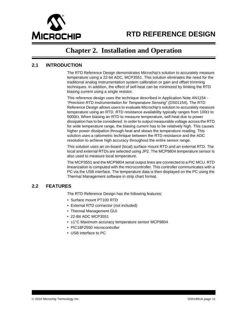
This solution uses an on-board (local) surface mount RTD and an external RTD. The local and external RTDs are selected using JP2. The MCP9804 temperature sensor is also used to measure local temperature.
The MCP3551 and the MCP9804 serial output lines are connected to a PIC MCU. RTD linearization is computed with the microcontroller. This controller communicates with a PC via the USB interface. The temperature data is then displayed on the PC using the Thermal Management software in strip chart format.
2.2 FEATURES
The RTD Reference Design has the following features:
• Surface mount PT100 RTD
• External RTD connector (not included)
• Thermal Management GUI
• 22-Bit ADC MCP3551
• ±1°C Maximum accuracy temperature sensor MCP9804
• PIC18F2550 microcontroller
• USB interface to PC
2010 Microchip Technology Inc. DS51891A-page 11
RTD Reference Design
2.3 GETTING STARTED
This section describes how to quickly configure the RTD Reference Design. A simplified block diagram of the configuration is provided in Figure 2-1.
FIGURE 2-1: RTD Reference Design Simplified Block Diagram.
2.3.1 Hardware Setup
1. Connect the USB cable to PC
2. Select JP2 for Local/External RTD
3. Start the Thermal Management software
2.3.2 Software Setup
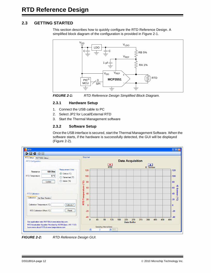
Once the USB interface is secured, start the Thermal Management Software. When the software starts, if the hardware is successfully detected, the GUI will be displayed (Figure 2-2).
FIGURE 2-2: RTD Reference Design GUI.
RTD
RA 1%
LDO
VDD
SPI3PIC®
RB 5%
VREF
MCP3551
+
-
VREF
VLDO
C
1 µf
MCU
VDD
C
DS51891A-page 12 2010 Microchip Technology Inc.
Installation and Operation
This configuration window allows the user to set some parameters, such as measurement unit and calibration temperature.
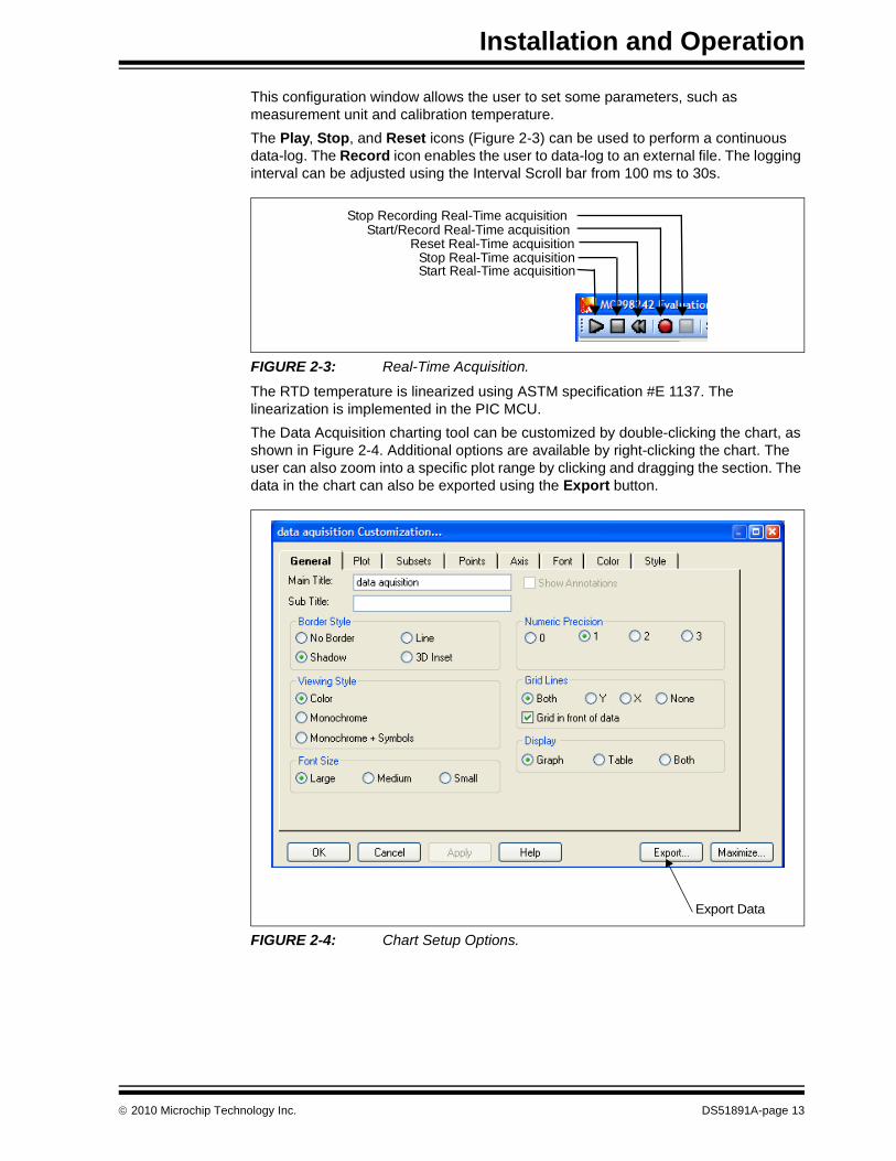
The Play, Stop, and Reset icons (Figure 2-3) can be used to perform a continuous data-log. The Record icon enables the user to data-log to an external file. The logging interval can be adjusted using the Interval Scroll bar from 100 ms to 30s.
FIGURE 2-3: Real-Time Acquisition.
The RTD temperature is linearized using ASTM specification #E 1137. The linearization is implemented in the PIC MCU.
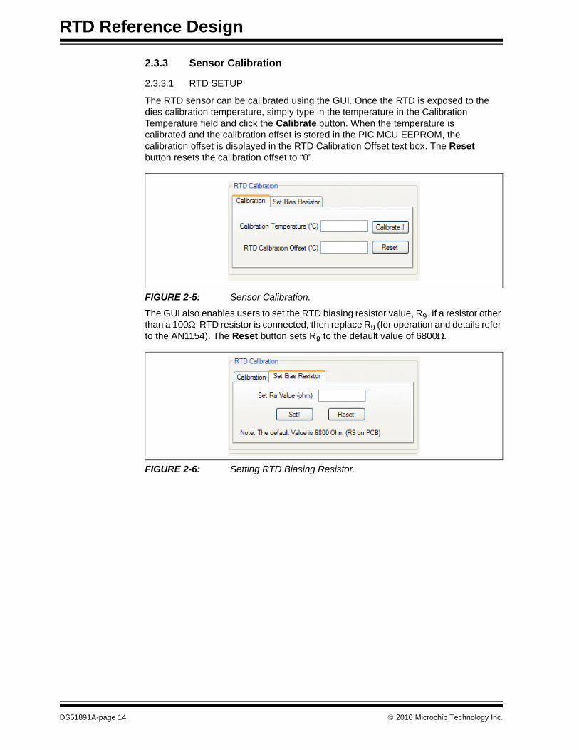
The Data Acquisition charting tool can be customized by double-clicking the chart, as shown in Figure 2-4. Additional options are available by right-clicking the chart. The user can also zoom into a specific plot range by clicking and dragging the section. The data in the chart can also be exported using the Export button.
FIGURE 2-4: Chart Setup Options.
Start Real-Time acquisitionStop Real-Time acquisition
Reset Real-Time acquisitionStart/Record Real-Time acquisition
Stop Recording Real-Time acquisition
Export Data
2010 Microchip Technology Inc. DS51891A-page 13
RTD Reference Design
2.3.3 Sensor Calibration
2.3.3.1 RTD SETUP
The RTD sensor can be calibrated using the GUI. Once the RTD is exposed to the dies calibration temperature, simply type in the temperature in the Calibration Temperature field and click the Calibrate button. When the temperature is calibrated and the calibration offset is stored in the PIC MCU EEPROM, the calibration offset is displayed in the RTD Calibration Offset text box. The Reset button resets the calibration offset to “0”.
FIGURE 2-5: Sensor Calibration.
The GUI also enables users to set the RTD biasing resistor value, R9. If a resistor other than a 100 RTD resistor is connected, then replace R9 (for operation and details refer to the AN1154). The Reset button sets R9 to the default value of 6800.
FIGURE 2-6: Setting RTD Biasing Resistor.
DS51891A-page 14 2010 Microchip Technology Inc.
Installation and Operation
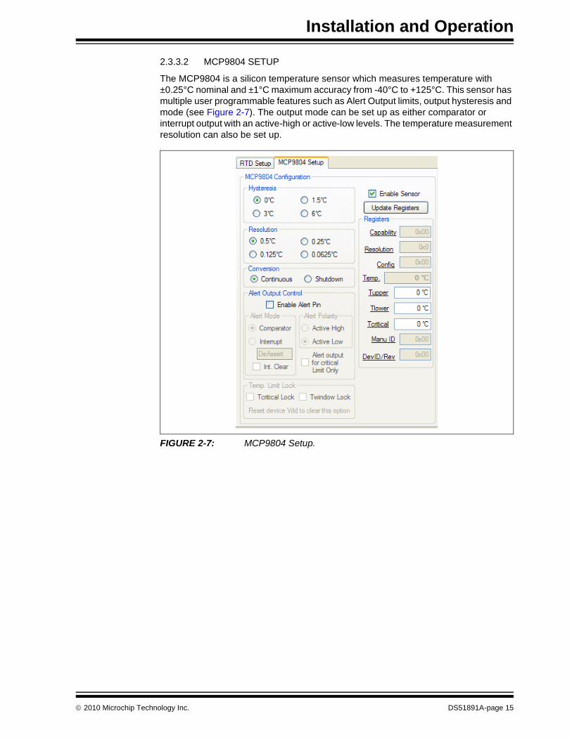
2.3.3.2 MCP9804 SETUP
The MCP9804 is a silicon temperature sensor which measures temperature with ±0.25°C nominal and ±1°C maximum accuracy from -40°C to +125°C. This sensor has multiple user programmable features such as Alert Output limits, output hysteresis and mode (see Figure 2-7). The output mode can be set up as either comparator or interrupt output with an active-high or active-low levels. The temperature measurement resolution can also be set up..
FIGURE 2-7: MCP9804 Setup.
2010 Microchip Technology Inc. DS51891A-page 15

RTD Reference Design
NOTES:
DS51891A-page 16 2010 Microchip Technology Inc.
RTD REFERENCE DESIGN
Appendix A. Schematic and Layouts
A.1 INTRODUCTION
This appendix contains the following schematics and layouts for the RTD Reference Design:
• Board – Schematic
• Board – Top Silk and Pads
• Board – Top Layer
• Board – Bottom Silk and Pads
• Board – Bottom Layer
2010 Microchip Technology Inc. DS51891A-page 17
RTD Reference Design
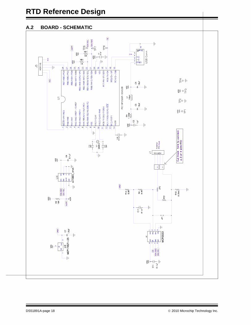
A.2 BOARD - SCHEMATIC
DS51891A-page 18 2010 Microchip Technology Inc.
Schematic and Layouts
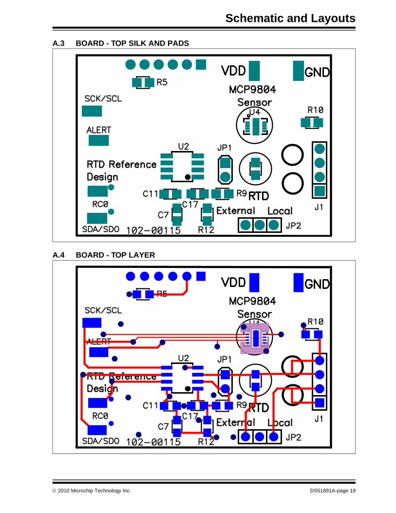
A.3 BOARD - TOP SILK AND PADS
A.4 BOARD - TOP LAYER
2010 Microchip Technology Inc. DS51891A-page 19
RTD Reference Design
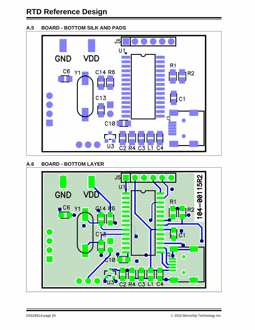
A.5 BOARD - BOTTOM SILK AND PADS
A.6 BOARD - BOTTOM LAYER
DS51891A-page 20 2010 Microchip Technology Inc.
RTD REFERENCE DESIGN
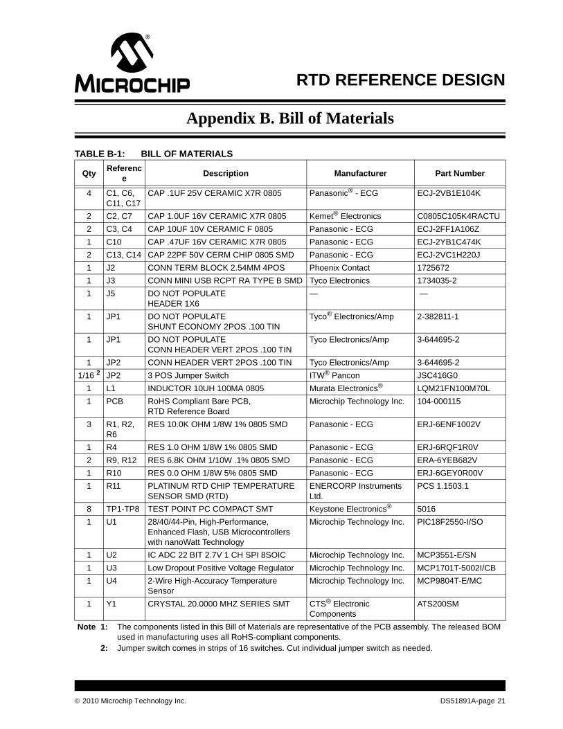
Appendix B. Bill of Materials
TABLE B-1: BILL OF MATERIALS
QtyReferenc
eDescription Manufacturer Part Number
4 C1, C6, C11, C17
CAP .1UF 25V CERAMIC X7R 0805 Panasonic® - ECG ECJ-2VB1E104K
2 C2, C7 CAP 1.0UF 16V CERAMIC X7R 0805 Kemet® Electronics C0805C105K4RACTU
2 C3, C4 CAP 10UF 10V CERAMIC F 0805 Panasonic - ECG ECJ-2FF1A106Z
1 C10 CAP .47UF 16V CERAMIC X7R 0805 Panasonic - ECG ECJ-2YB1C474K
2 C13, C14 CAP 22PF 50V CERM CHIP 0805 SMD Panasonic - ECG ECJ-2VC1H220J
1 J2 CONN TERM BLOCK 2.54MM 4POS Phoenix Contact 1725672
1 J3 CONN MINI USB RCPT RA TYPE B SMD Tyco Electronics 1734035-2
1 J5 DO NOT POPULATEHEADER 1X6
— —
1 JP1 DO NOT POPULATESHUNT ECONOMY 2POS .100 TIN
Tyco® Electronics/Amp 2-382811-1
1 JP1 DO NOT POPULATECONN HEADER VERT 2POS .100 TIN
Tyco Electronics/Amp 3-644695-2
1 JP2 CONN HEADER VERT 2POS .100 TIN Tyco Electronics/Amp 3-644695-2
1/16 2 JP2 3 POS Jumper Switch ITW® Pancon JSC416G0
1 L1 INDUCTOR 10UH 100MA 0805 Murata Electronics® LQM21FN100M70L
1 PCB RoHS Compliant Bare PCB, RTD Reference Board
Microchip Technology Inc. 104-000115
3 R1, R2, R6
RES 10.0K OHM 1/8W 1% 0805 SMD Panasonic - ECG ERJ-6ENF1002V
1 R4 RES 1.0 OHM 1/8W 1% 0805 SMD Panasonic - ECG ERJ-6RQF1R0V
2 R9, R12 RES 6.8K OHM 1/10W .1% 0805 SMD Panasonic - ECG ERA-6YEB682V
1 R10 RES 0.0 OHM 1/8W 5% 0805 SMD Panasonic - ECG ERJ-6GEY0R00V
1 R11 PLATINUM RTD CHIP TEMPERATURE SENSOR SMD (RTD)
ENERCORP Instruments Ltd.
PCS 1.1503.1
8 TP1-TP8 TEST POINT PC COMPACT SMT Keystone Electronics® 5016
1 U1 28/40/44-Pin, High-Performance, Enhanced Flash, USB Microcontrollers with nanoWatt Technology
Microchip Technology Inc. PIC18F2550-I/SO
1 U2 IC ADC 22 BIT 2.7V 1 CH SPI 8SOIC Microchip Technology Inc. MCP3551-E/SN
1 U3 Low Dropout Positive Voltage Regulator Microchip Technology Inc. MCP1701T-5002I/CB
1 U4 2-Wire High-Accuracy Temperature Sensor
Microchip Technology Inc. MCP9804T-E/MC
1 Y1 CRYSTAL 20.0000 MHZ SERIES SMT CTS® Electronic Components
ATS200SM
Note 1: The components listed in this Bill of Materials are representative of the PCB assembly. The released BOM used in manufacturing uses all RoHS-compliant components.
2: Jumper switch comes in strips of 16 switches. Cut individual jumper switch as needed.
2010 Microchip Technology Inc. DS51891A-page 21
DS51891A-page 22 2010 Microchip Technology Inc.
AMERICASCorporate Office2355 West Chandler Blvd.Chandler, AZ 85224-6199Tel: 480-792-7200 Fax: 480-792-7277Technical Support: http://support.microchip.comWeb Address: www.microchip.com
AtlantaDuluth, GA Tel: 678-957-9614 Fax: 678-957-1455
BostonWestborough, MA Tel: 774-760-0087 Fax: 774-760-0088
ChicagoItasca, IL Tel: 630-285-0071 Fax: 630-285-0075
ClevelandIndependence, OH Tel: 216-447-0464 Fax: 216-447-0643
DallasAddison, TX Tel: 972-818-7423 Fax: 972-818-2924
DetroitFarmington Hills, MI Tel: 248-538-2250Fax: 248-538-2260
KokomoKokomo, IN Tel: 765-864-8360Fax: 765-864-8387
Los AngelesMission Viejo, CA Tel: 949-462-9523 Fax: 949-462-9608
Santa ClaraSanta Clara, CA Tel: 408-961-6444Fax: 408-961-6445
TorontoMississauga, Ontario, CanadaTel: 905-673-0699 Fax: 905-673-6509
ASIA/PACIFICAsia Pacific OfficeSuites 3707-14, 37th FloorTower 6, The GatewayHarbour City, KowloonHong KongTel: 852-2401-1200Fax: 852-2401-3431
Australia - SydneyTel: 61-2-9868-6733Fax: 61-2-9868-6755
China - BeijingTel: 86-10-8528-2100 Fax: 86-10-8528-2104
China - ChengduTel: 86-28-8665-5511Fax: 86-28-8665-7889
China - ChongqingTel: 86-23-8980-9588Fax: 86-23-8980-9500
China - Hong Kong SARTel: 852-2401-1200 Fax: 852-2401-3431
China - NanjingTel: 86-25-8473-2460Fax: 86-25-8473-2470
China - QingdaoTel: 86-532-8502-7355Fax: 86-532-8502-7205
China - ShanghaiTel: 86-21-5407-5533 Fax: 86-21-5407-5066
China - ShenyangTel: 86-24-2334-2829Fax: 86-24-2334-2393
China - ShenzhenTel: 86-755-8203-2660 Fax: 86-755-8203-1760
China - WuhanTel: 86-27-5980-5300Fax: 86-27-5980-5118
China - XianTel: 86-29-8833-7252Fax: 86-29-8833-7256
China - XiamenTel: 86-592-2388138 Fax: 86-592-2388130
China - ZhuhaiTel: 86-756-3210040 Fax: 86-756-3210049
ASIA/PACIFICIndia - BangaloreTel: 91-80-3090-4444 Fax: 91-80-3090-4123
India - New DelhiTel: 91-11-4160-8631Fax: 91-11-4160-8632
India - PuneTel: 91-20-2566-1512Fax: 91-20-2566-1513
Japan - YokohamaTel: 81-45-471- 6166 Fax: 81-45-471-6122
Korea - DaeguTel: 82-53-744-4301Fax: 82-53-744-4302
Korea - SeoulTel: 82-2-554-7200Fax: 82-2-558-5932 or 82-2-558-5934
Malaysia - Kuala LumpurTel: 60-3-6201-9857Fax: 60-3-6201-9859
Malaysia - PenangTel: 60-4-227-8870Fax: 60-4-227-4068
Philippines - ManilaTel: 63-2-634-9065Fax: 63-2-634-9069
SingaporeTel: 65-6334-8870Fax: 65-6334-8850
Taiwan - Hsin ChuTel: 886-3-6578-300Fax: 886-3-6578-370
Taiwan - KaohsiungTel: 886-7-213-7830Fax: 886-7-330-9305
Taiwan - TaipeiTel: 886-2-2500-6610 Fax: 886-2-2508-0102
Thailand - BangkokTel: 66-2-694-1351Fax: 66-2-694-1350
EUROPEAustria - WelsTel: 43-7242-2244-39Fax: 43-7242-2244-393Denmark - CopenhagenTel: 45-4450-2828 Fax: 45-4485-2829
France - ParisTel: 33-1-69-53-63-20 Fax: 33-1-69-30-90-79
Germany - MunichTel: 49-89-627-144-0 Fax: 49-89-627-144-44
Italy - Milan Tel: 39-0331-742611 Fax: 39-0331-466781
Netherlands - DrunenTel: 31-416-690399 Fax: 31-416-690340
Spain - MadridTel: 34-91-708-08-90Fax: 34-91-708-08-91
UK - WokinghamTel: 44-118-921-5869Fax: 44-118-921-5820
WORLDWIDE SALES AND SERVICE
08/04/10


![[PSS 6-1C3 A] DolpHin PH10 and ORP10indecx.co.za. · PSS 6-1C3 A Page 5 AUTOMATIC TEMPERATURE COMPENSATION ATC, utilizing a resistance temperature detector (RTD), is a built-in feature](https://img.pdfslide.us/doc/110x75/5b642d387f8b9a687e8cff63/pss-6-1c3-a-dolphin-ph10-and-pss-6-1c3-a-page-5-automatic-temperature-compensation.jpg)