Embed Size (px)
Citation preview

Resistance Welding
of
Butted Rings By Eric Matwe

© 2010 by Eric Matwe
All rights reserved.
No part of this book may be used or reproduced in any manner
whatsoever without prior written permission except in the case
of brief quotations under the doctrine of fair dealing.
Published by
Lady Lu
Computer Support
&
Print Shop
Riverhurst, SK
CANADA
Cover picture courtesy of TheRingLord.com

Product Liability Disclaimer Terms of Use, Warranty and Liability Waiver
TheRingLord.com offers this product with the terms conditions and notices as follows:
Terms of Use
This product is offered to you conditional upon your acceptance without modification of the terms,
conditions, and notices contained.
Exclusive Obligation
This product has been designed for the purpose of welding rings. This product may not be used for
any purpose other than that intended, such use is strictly prohibited under the terms and conditions of its
use.
Warranty
This product is not manufactured by TheRingLord.com and TheRingLord.com therefore offers no
warranty or implied warranty of fitness for any particular purpose.
Limitation of Liability
In no event shall TheRingLord.com be liable for any direct, indirect, punitive, incidental, special
consequential damages whatsoever arising out of or connected with the use or misuse of this product.
Other Statements
TheRingLord.com employees or representatives, oral or other written statements, do not constitute
warranties, shall not be relied upon by the buyer, and is not part of the contract for sale.
Entire Obligation
This Product Liability Disclaimer document states the entire obligation of TheRingLord.com with
respect to this product. If any part of this disclaimer is determined to be void, invalid, unenforceable or
illegal, including, but not limited to the warranty disclaimers and liability disclaimers and liability limi-
tations set forth above, then the invalid or unenforceable provision will be deemed superseded by a
valid, enforceable provision that closely matches the intent of the original provision and the remainder
of the agreement will remain in full force and effect.
General
This disclaimer statement is governed by the laws of the province of Saskatchewan, Canada. You
hereby consent to the exclusive jurisdiction and venue of the Courts of competent jurisdiction, Canada,
in all disputes arising out of or relating to the use of this product. Use of this product is unauthorized in
any jurisdiction that does not give effect to all provisions of these terms and conditions, including with-
out limitation this paragraph.
Modification of Terms and Conditions
TheRingLord.com reserves the right to change the terms, conditions, and notices under which this
product is offered.

Table Of Contents
Introduction.................................................................................page 1
Welding Precautions....................................................................page 2
Included In this Kit......................................................................page 3
Setting Up Your Welder...............................................................page 4
Power Source
Electrode Assembly
Timing Circuit.......................................................................page 5
Optional Variac
Welder Diagram...........................................................................page 6
Circuit Diagram...........................................................................page 7
How Resistance Works................................................................page 8
Resistance
Current
Voltage
The Weld Cycle...........................................................................page 9
Squeeze Time
Weld Time
Hold Time
Welder Variables........................................................................page 10
Electrode Position
Weld Duration

Material Variables......................................................................page 11
Cleanliness
Wire Diameter
Aspect Ratio........................................................................page 12
Cuts
Operator Variables.....................................................................page 13
Pressure
Electrode Maintenance
Commonly Used Metals............................................................page 14
Iron & Steel
Brass & Bronze
Niobium & Titanium...........................................................page 15
Aluminum, Copper, Silver & Gold.
Types Of Welds..........................................................................page 16
Solid Welds
Upset Welds
Flash Welds
Bad Welds............................................................................page 17
Examples Of Welded Rings.......................................................page 18
Weld Strength............................................................................page 19
Conclusion.................................................................................page 20

Introduction
This document is intended to be a practical guide to welding
butted rings using a resistance welder. It is being distributed as a
companion to the resistance welder kit designed by the author and
distributed through TheRingLord.com's website. The information pre-
sented throughout this document will be referring specifically to
those resistance welders but may also apply to resistance welders in
general.
This is not a user manual, please take the time to read the instruc-
tions and safety precautions in the original equipment manufacturer
(OEM)'s user manual that came with your welder.
1

2
Welding Precautions
As with any electrical device be aware that electrical shocks
can potentially be fatal. Don't operate the welder in damp or wet
conditions or expose it to water. Don't let your body touch a
grounding surface while operating the welder. Inspect electrical
components for damage before using the welder. Be aware that the
electrodes are live during operation of the welder.
The electrical currents involved in welding create a strong
magnetic field. This magnetic field can disrupt electronics and
medical devices such as pacemakers. Any person who uses such a
medical device should consult with their physician before attempt-
ing to use any welding equipment.
Resistance welding involves heating metal to near its melting
point. Too much heat can cause an expulsion of sparks and molten
metal droplets. Do not operate your welder near anything flamma-
ble, or with children or pets nearby.
Your welding kit contains a pair of heat resistant gloves to
wear while welding. You may also want to buy a clear plastic face
shield to protect your face and eyes from stray sparks. It is best to
wear clothing that fits well and covers your arms, legs and feet to
avoid burns. Avoid open toed shoes, sandals and low cut necklines.
Synthetic fibres and terrycloth catch fire easily from sparks, do not
wear them.

Included In This Kit
1. 115V AC resistance welder transformer
2. Electrode assembly
a) 2X Mounting arms
b) 2X Brackets
c) 4X M6 nuts & bolts
d) 2X M8 nuts
e) 2X SH16516 rings
f) 2X copper terminals
g) 2X 6” copper cable
h) 2X electrodes
i) 4X insulating washers
3. Timing assembly
a) Timer
b) Foot switch
c) Power cord
d) 4X clear terminals
e) #10-32 bolt
f) 2X yellow terminals
4. 1 pair heat resistant gloves
5. Sample welded rings
6. OEM Manual
7. Resistance Welding of Butted Rings booklet
3
4
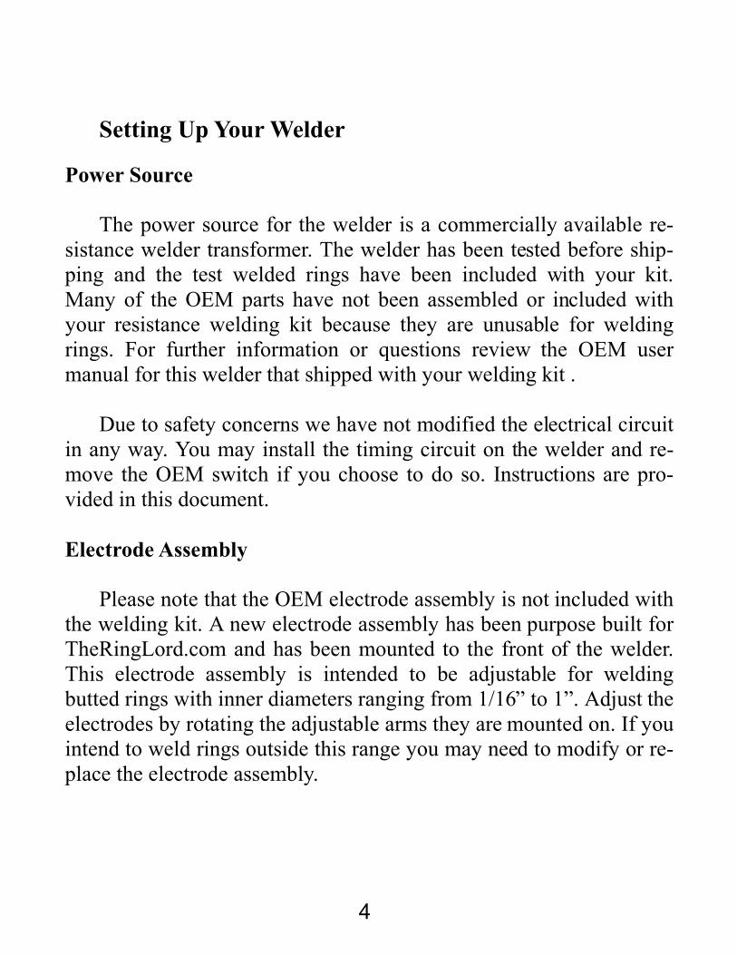
Setting Up Your Welder
Power Source
The power source for the welder is a commercially available re-
sistance welder transformer. The welder has been tested before ship-
ping and the test welded rings have been included with your kit.
Many of the OEM parts have not been assembled or included with
your resistance welding kit because they are unusable for welding
rings. For further information or questions review the OEM user
manual for this welder that shipped with your welding kit .
Due to safety concerns we have not modified the electrical circuit
in any way. You may install the timing circuit on the welder and re-
move the OEM switch if you choose to do so. Instructions are pro-
vided in this document.
Electrode Assembly
Please note that the OEM electrode assembly is not included with
the welding kit. A new electrode assembly has been purpose built for
TheRingLord.com and has been mounted to the front of the welder.
This electrode assembly is intended to be adjustable for welding
butted rings with inner diameters ranging from 1/16” to 1”. Adjust the
electrodes by rotating the adjustable arms they are mounted on. If you
intend to weld rings outside this range you may need to modify or re-
place the electrode assembly.
5
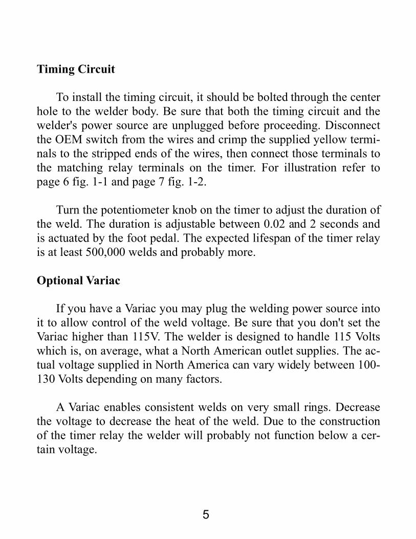
Timing Circuit
To install the timing circuit, it should be bolted through the center
hole to the welder body. Be sure that both the timing circuit and the
welder's power source are unplugged before proceeding. Disconnect
the OEM switch from the wires and crimp the supplied yellow termi-
nals to the stripped ends of the wires, then connect those terminals to
the matching relay terminals on the timer. For illustration refer to
page 6 fig. 1-1 and page 7 fig. 1-2.
Turn the potentiometer knob on the timer to adjust the duration of
the weld. The duration is adjustable between 0.02 and 2 seconds and
is actuated by the foot pedal. The expected lifespan of the timer relay
is at least 500,000 welds and probably more.
Optional Variac
If you have a Variac you may plug the welding power source into
it to allow control of the weld voltage. Be sure that you don't set the
Variac higher than 115V. The welder is designed to handle 115 Volts
which is, on average, what a North American outlet supplies. The ac-
tual voltage supplied in North America can vary widely between 100-
130 Volts depending on many factors.
A Variac enables consistent welds on very small rings. Decrease
the voltage to decrease the heat of the weld. Due to the construction
of the timer relay the welder will probably not function below a cer-
tain voltage.

6
Welder Diagram
Fig. 1-1

7
Circuit Diagram
Fig. 1-2
8
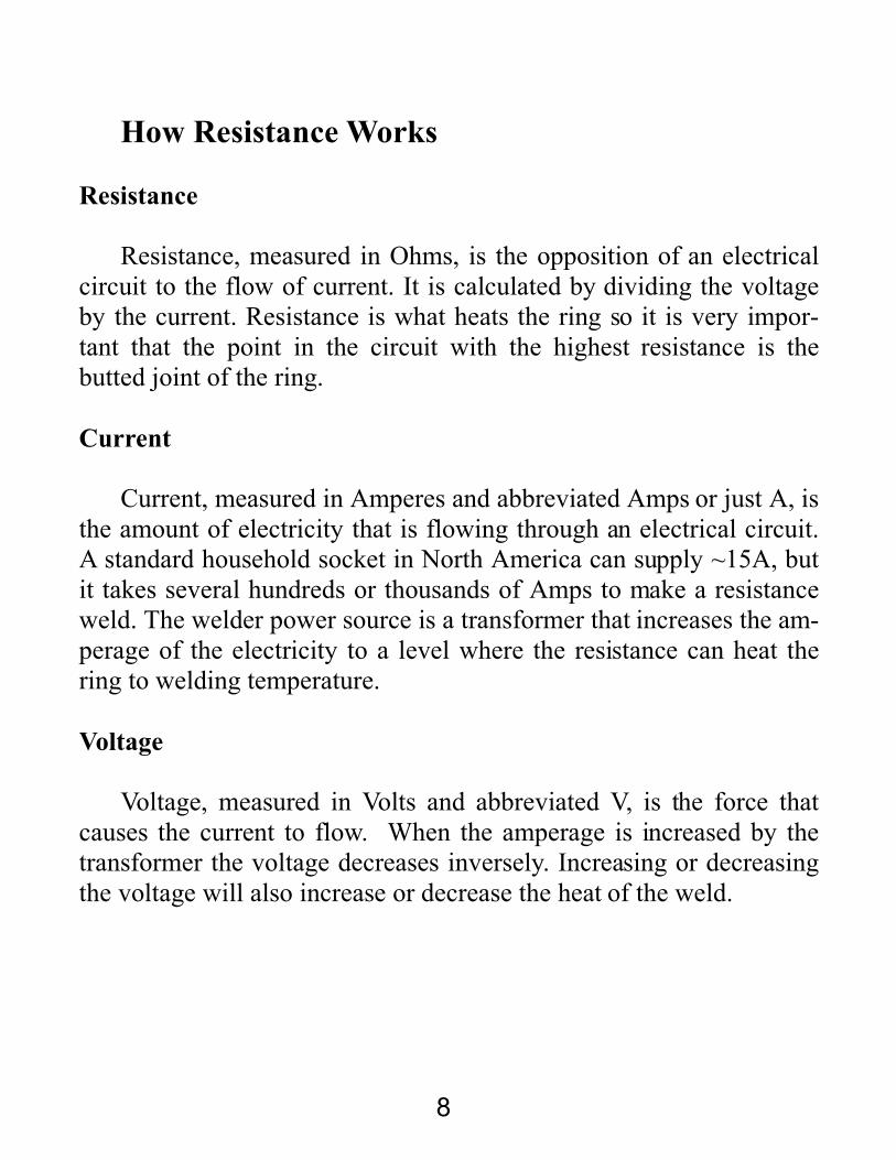
How Resistance Works
Resistance
Resistance, measured in Ohms, is the opposition of an electrical
circuit to the flow of current. It is calculated by dividing the voltage
by the current. Resistance is what heats the ring so it is very impor-
tant that the point in the circuit with the highest resistance is the
butted joint of the ring.
Current
Current, measured in Amperes and abbreviated Amps or just A, is
the amount of electricity that is flowing through an electrical circuit.
A standard household socket in North America can supply ~15A, but
it takes several hundreds or thousands of Amps to make a resistance
weld. The welder power source is a transformer that increases the am-
perage of the electricity to a level where the resistance can heat the
ring to welding temperature.
Voltage
Voltage, measured in Volts and abbreviated V, is the force that
causes the current to flow. When the amperage is increased by the
transformer the voltage decreases inversely. Increasing or decreasing
the voltage will also increase or decrease the heat of the weld.

9
The Weld Cycle
Squeeze Time
A resistance weld is separated into 3 distinct phases. First there is
the squeeze time. This is the period of time just before current is ap-
plied when the operator presses the ring against the electrodes with a
constant pressure.
Weld Time
The second phase is the weld time. During this phase the operator
maintains the pressure on the ring while applying current. This heats
the metal of the ring to a plastic or liquid state and forces the ends to-
gether creating the weld.
Hold Time
The third and final phase is the hold time. This phase begins as
soon as the current has stopped flowing through the ring. During this
phase the operator must continue to maintain pressure against the ring
until the metal has cooled to the point where it is solid again.
10
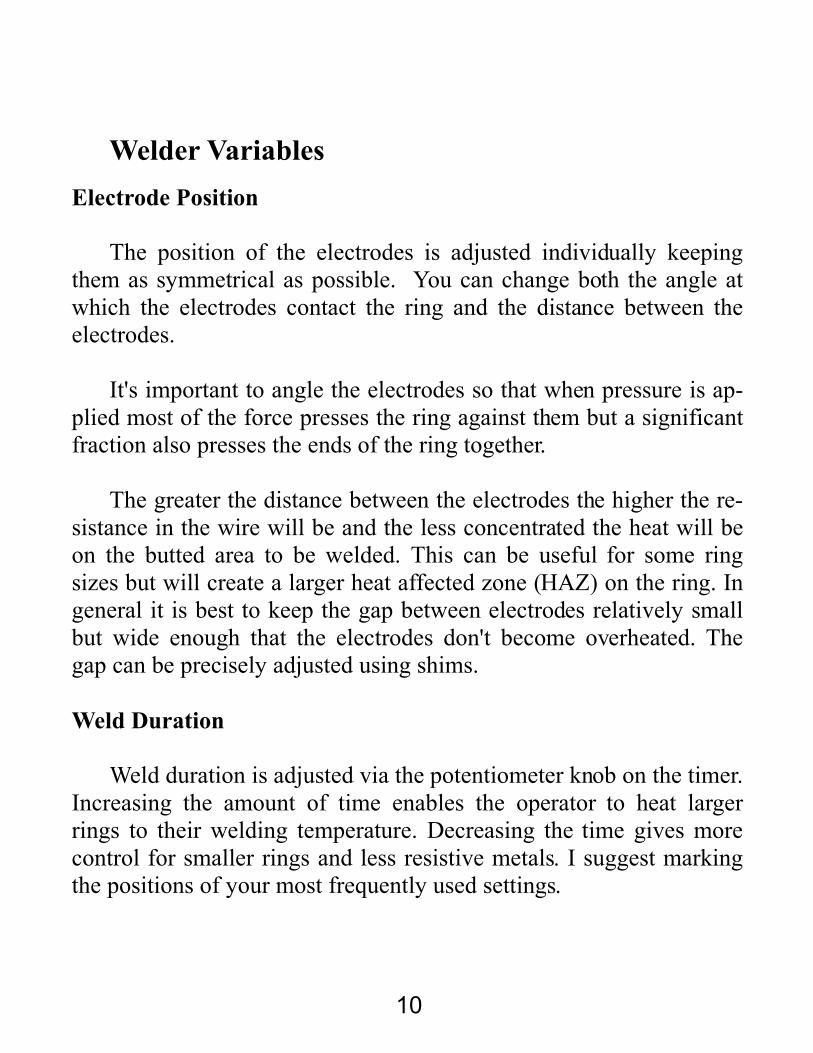
Welder Variables
Electrode Position
The position of the electrodes is adjusted individually keeping
them as symmetrical as possible. You can change both the angle at
which the electrodes contact the ring and the distance between the
electrodes.
It's important to angle the electrodes so that when pressure is ap-
plied most of the force presses the ring against them but a significant
fraction also presses the ends of the ring together.
The greater the distance between the electrodes the higher the re-
sistance in the wire will be and the less concentrated the heat will be
on the butted area to be welded. This can be useful for some ring
sizes but will create a larger heat affected zone (HAZ) on the ring. In
general it is best to keep the gap between electrodes relatively small
but wide enough that the electrodes don't become overheated. The
gap can be precisely adjusted using shims.
Weld Duration
Weld duration is adjusted via the potentiometer knob on the timer.
Increasing the amount of time enables the operator to heat larger
rings to their welding temperature. Decreasing the time gives more
control for smaller rings and less resistive metals. I suggest marking
the positions of your most frequently used settings.
11
Material Variables
Cleanliness
Any contaminants on the ring's cut area, such as dust, oil, or ox-
ides can interfere with getting a good weld. In some cases contami-
nants can prevent any welding or cause the welds to become very
brittle. Freshly cut rings are usually free of contaminants but saw cut
or machine cut rings may have residual oil or grease from lubrication.
Ultrasonic cleaners are the best way to remove contaminants from
cuts. Washing with detergent and water is also usually effective.
Conversely, purposely contaminating a weld joint can be used
beneficially to create more resistance or prevent oxidation in difficult
to weld metals. This is an advanced technique and specific details are
usually guarded as trade secrets.
Wire Diameter
The thickness of the wire affects the resistance; thinner wire will
have more resistance and therefore require less heat and time to weld.
Thicker wire transfers more heat away from the weld area and is
stronger requiring more heat and pressure to weld properly. Trying to
weld wire larger than 12g is possible but can result in problems such
as operator fatigue, damaged electrodes and shortened welder life.

12
Aspect Ratio
The aspect ratio (AR) of a ring is the ratio of its inner diameter to
the diameter of the wire. As the aspect ratio decreases the ring will re-
quire more pressure to weld properly. Rings with an aspect ratio of
4:1 or less may be difficult for some people to weld. As the aspect ra-
tio increases or decreases the electrodes should be adjusted outwards
or inwards to compensate for the changing angle between the ring
and electrodes.
Cuts
Pinch cut rings have the highest resistance at the cut so they start
a weld easily but have problems with the ring ends slipping off each
other as they melt under pressure. This usually results in off round
rings and large burrs in the weld. The welds are generally strong and
with aggressive tumbling are good for armor.
Shear cut and machine cut rings are of roughly equal quality.
They weld easily and don't slip often, resulting in a more rounded
ring. Because the ends are more flush they generally have smaller
burrs and more consistent welds can be made. These types of rings
are ideal for most applications.
Saw cut rings can be a little more difficult to weld since the cut
has lower resistance, however these rings give the nicest looking
welds with little to no burring. If you are making jewelry then these
are definitely the rings you want. Be aware that due to the gap be-
tween the ends these rings will become more ovoid than shear cut
rings.

13
Operator Variables
Pressure
There are two variables that must be controlled manually by the
operator. The first variable is pressure. As pressure is increased resis-
tance will decrease. The more pressure that is applied between the
ring and the electrode the less heat will be generated there and the
more heat will be generated directly between the butted ends. This
helps minimize the heat affected zone and also presses the butted
ends together ensuring a good weld.
It is important to apply consistent pressure to the ring throughout
the three phases of the weld cycle. Too much pressure will create a
large burr or misalignment in the weld. Too little pressure will result
in brittle welds.
Electrode Maintenance
The second variable is electrode maintenance. Keeping the elec-
trodes clean and undamaged ensures correct alignment of the ring's
ends and low resistance between the ring and electrodes. Electrodes
should be cleaned and repaired by dressing them lightly with a fine
toothed triangular file.
When the electrodes become badly worn or damaged they must
be replaced. TheRingLord.com has replacement electrodes available.

14
Commonly Used Metals
Iron & Steel
Iron and iron alloys, notably the various types of steel, are the
most commonly welded metals. These metals resistance weld easily.
The corrosion resistance of stainless steel will be somewhat reduced
during the welding process but can be mostly restored by polishing
off the oxide layer. Resistance welds made in steel or iron should be
stronger than the original wire. Steel alloys with a large amount of
carbon may need special heat treating after they have been welded,
otherwise the heat affected zone can become very brittle.
The fumes produced from welding galvanized or zinc chromate
plated steel are toxic and will make you very sick. Do not weld
these materials.
Brass & Bronze
Brass and bronze are copper alloys. Copper is a very low resis-
tance metal, which is why the welder's electrodes are made from it.
Very good resistance welds can be made with most copper alloys but
the weld timer will need to be set for shorter periods compared to iron
alloys. Using a Variac to decrease the voltage is useful for smaller
wire sizes. With practice the welds in either metal can be made
stronger than the original wire but in many cases it's more practical to
make welds that are just strong enough for the application.

15
Titanium & Niobium
Titanium and niobium are reactive metals. When heated in air
they readily form brittle oxides with atmospheric oxygen. In most
welding processes they cannot be welded unless they are covered
with inert gases such as argon or helium. Resistance welding is an
exception.
By using very fast weld times and high pressure, the metal can be
welded before it has a chance to oxidize. This technique is also
known as a solid state bond, since the metal will not be entirely mol-
ten when welded. Some oxides will form but the pressure of the weld
should help to expel them from the weld joint.
Reactive metals are relatively expensive and when welding them
you should expect a higher than normal amount of bad welds. Keep
this in mind when estimating material costs. In many cases it may be
less expensive to use inert gas shielding for consistently good welds.
Aluminum, Copper, Silver & Gold
In theory any metal can be resistance welded but in practice some
are just too difficult without very expensive equipment. The metals
that are most difficult to weld are silver, gold, copper, and aluminum,
in that order. All of these metals have very low resistances and tend to
melt or blow apart when you try to weld them. Silver and gold in par-
ticular should not be resistance welded since they are much more ex-
pensive and also very easy to solder or braze.

16
Types Of Welds
Solid Welds
Solid welding refers to the technique of setting the heat or weld
time lower than normal to create a weld area where there is little to
no flow of metal. A solid weld is most useful for cosmetic purposes
when working with saw cut rings. It can be a full strength weld but is
more likely to be 60-90% strength, which is still many times the
strength of a butted ring. Precise settings and low pressure are re-
quired to get good solid welds. See page 18 fig. 2-1.
Upset Welds
Upset welds are the preferred welds for most applications, they
are usually stronger than the wire the ring is made from. To make an
upset weld you must ensure that there is enough heat and pressure so
that the metal becomes plastic when it is forced together and creates a
widened (upset) area around the welded joint. During this process any
oxidation is squeezed outwards from the weld area in a similar man-
ner to forge welding. See page 18 fig. 2-2.
Flash welds
Flash welds are a result of the upset area liquefying due to extra
heat and pressure and forming a large circular burr, known as flash.
This is a strong weld in most metals but the ring will be more oval
shaped and the flash may chafe against skin. Usually the flash can be
smoothed off to an acceptable level. See page 18 fig. 2-3.
17
Bad Welds
There are many types of bad welds and combinations thereof; I've
listed a few of the most common. They usually have a major draw-
back for typical uses.
Tack welds look similar to a solid weld but are more brittle. They
are caused either by contamination of the weld or by not enough weld
heat. Tack welds may be acceptable for some non-strength critical ap-
plications. Trying to re-weld tack welded rings seldom results in a
good bond. See page 18 fig. 2-4.
Misaligned welds occur when the ends slip away from each other
during the weld time. Alignment problems can normally be resolved
by proper electrode adjustment. They are not much weaker but can
chafe and are an eyesore in jewelry because they are off round. A
slight misalignment or burr can often be flattened by squeezing it be-
tween the jaws of smooth faced pliers. See page 18 fig. 2-5.
Burnt welds are caused by too much weld time without sufficient
pressure. In these welds the metal has been overheated and begun to
oxidize, this causes at least a portion of the weld area to turn to slag.
The metal in the weld area will usually sag or crumble. In extreme
cases a large section of the ring can liquefy and spray droplets of
molten metal. If the welds are only slightly burnt and not yet brittle
then they may be used for applications where appearance is not a
concern. See page 18 fig. 2-6.

18
Examples of Welded Rings
Fig. 2-1* Fig. 2-2*
A typical solid welded ring. A typical upset welded ring.
Before and after strength test. Before and after strength test.
Fig.2-3* Fig. 2-4
A typical flash welded ring. A typical tack welded ring.
Before and after strength test. Before and after strength test.
Fig. 2-5* Fig. 2-6
A typical misaligned welded ring. A typical burnt welded ring.
Before and after strength test. Before and after strength test.
*Denotes strength tested rings which were badly deformed and
required flattening to improve image quality.
19
Weld Strength
Weld strength can be tested by pulling and twisting the ring be-
tween two pairs of pliers until it breaks or deforms. Always test the
strength of your welds after changing a welder or material variable.
When making armor it is a good idea to periodically test the strength
of your welds while you work.
If the ring breaks on the weld with no deformation of the ring
then it is less strong than the yield strength of the wire. This indicates
a tack weld which usually has much less than 50% of the strength of
the wire.
If the ring breaks on the weld with some deformation of the ring
then the weld is stronger than the yield strength of the wire but less
strong than the ultimate tensile strength of the wire. This is typical for
solid welds in most metals and flash welds in Ti and Nb. These welds
are fine for some applications, in commonly welded alloys they will
generally have between 60-90% of the strength of the strongest
welds.
If the ring breaks in a spot that is not on the weld then the weld is
stronger than the ultimate tensile strength of the wire. This is the
strongest that any welded ring can be, the weld strength is 100% or
higher. The ring will usually break on the wire directly adjacent to
where it has been clamped.

20
Conclusion
Welding is a complex process which requires practice and skill. I
have compiled most of the basic principles of resistance welding, as
they apply to butted rings, but there is much more to learn that falls
outside the scope of this document.
TheRingLord.com's discussion forum is there for you if you have
problems using your resistance welding kit or want to share your own
tips with other users.
http://www.theringlord.org/forum/Index.php
On the forum you can interact with other users of the resistance
welding kit or get help directly from TheRingLord.com's profession-
als.
As an active member on the website I look forward to meeting
you there.
Eric “lorenzo” Matwe

Shop Notes
________________________________________________________
________________________________________________________
________________________________________________________
________________________________________________________
________________________________________________________
________________________________________________________
________________________________________________________
________________________________________________________
________________________________________________________
________________________________________________________
________________________________________________________
________________________________________________________
________________________________________________________
________________________________________________________
________________________________________________________
________________________________________________________
________________________________________________________
________________________________________________________
________________________________________________________
________________________________________________________
________________________________________________________
________________________________________________________
________________________________________________________
________________________________________________________
________________________________________________________
________________________________________________________
________________________________________________________
________________________________________________________
________________________________________________________
________________________________________________________
________________________________________________________

About the Author
Eric Matwe is a professional maille craftsman who spe-
cializes in welding and automated production techniques.
He has 5 years experience working at TheRingLord.com
and 3 years experience repairing maille armor for the meat
packing industry.
Prior to that he was a semi-professional maille enthusiast
and one of the founding members of the Maille Artisans
International League.