Embed Size (px)
Citation preview

SINCE 1950
RESI
STAN
CE W
ELD
ING
WWW.CEAWELD.COM 1
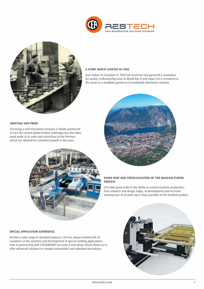
A STORY WHICH STARTED IN 1950
Even before its inception in 1950 CEA machines had garnered a reputation for quality craftsmanship prior to World War II and today CEA is renowned in the sector as a steadfast partner to its worldwide distributor network.
HERITAGE AND PRIDE
CEA being a well-structured company is ideally positioned to face the current global market challenges but also takes great pride in its roots and connection to the territory which has allowed for consistent growth in the years.
KNOW-HOW AND VERTICALIZATION OF THE MANUFACTURING PROCESS
CEA takes great pride in the ability to control machine production, from research and design stages, to development and in-house manufacture of all parts up to final assembly of the finished product.
SPECIAL APPLICATION EXPERIENCE
Besides a wide range of standard products, CEA has always worked with its customers in the solutions and development of special welding applications. Now in partnership with TECNOROBOT we enter a new phase which allows us to offer advanced solutions to complex automation and robotized procedures.
WWW.CEAWELD.COM
CEA: A LOW-ENERGY IMPACT FIRMCare for the environment has always been a fundamental value in the CEA corporate philosophy.This is proven by a keen attention towards an eco-sustainable production process, care in the selection of components, use of paints with low environmental impact and so on. The evolution of CEA’s manufacturing trend, focusing towards inverter technology, has allowed to greatly improve the energy efficiency of the products.CEA GOES GREEN is the hallmark of this approach and is reflected into latest generation inverter power sources which, versus traditional equipment, ensure a considerable energy saving:
• low energy consumption• compliance with “green” environment-friendly norms (e.g. RoHS)• reduced weight and dimensions for lower shipping costs, disposal and recycling (WEEE)An additional investment in the pursuit of “eco-sustainability” is represented by an important 200 kWp photovoltaic plant, which has made the company virtually self-sufficient from an energetic perspective.
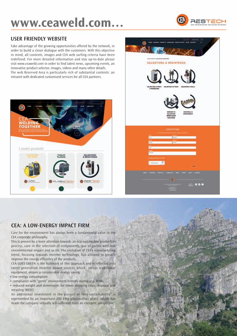
USER FRIENDLY WEBSITETake advantage of the growing opportunities offered by the network, in order to build a closer dialogue with the customers. With this objective in mind, all contents, images and CEA web surfing criteria have been redefined. For more detailed information and stay up-to-date please visit www.ceaweld.com in order to find latest news, upcoming events, an innovative product selector, images, videos and many other details.The web Reserved Area is particularly rich of substantial contents: an intranet with dedicated customized services for all CEA partners.
www.ceaweld.com…

3WWW.CEAWELD.COM
ISO 9001Always concerned about quality, CEA has its quality management system ISO 9001 certified since 1994. This is a guarantee of an ongoing commitment of the entire company for a continuous improvement in its products and business processes, leading to the full satisfaction of its customers.
CE MARKINGAll CEA products are CE marked, therefore compliant with all EU Directives and Standards imposing such utilization from design, manufacture and installation of the equipment up to its final disposal. In particular CE marking implies the conformity to the following main Directives:
2014/35/EU (LUD)The Low Voltage Directive (LVD) defines the compliance with numerous regulations to safeguard health and safety for the operator and also regarding the electrical dimensioning of the equipment.
2014/30/EU (EMC)The Directive on Electromagnetic compatibility (EMC) defines the effects of electromagnetic emissions and the immunity degree. This means that the equipment shall not emit any electromagnetic disturbances and, in turn, must be immune to any interference from other equipment or from the mains supply.
2011/65/EU (ROHS)The Directive defines the restriction of certain hazardous substances in electrical and electronic equipment.
2006/42/EEC (MD – MACHINE DIRECTIVE)Machine Directive (MD) defines the essential requirements related to design, manufacture and installation in order to improve safety of the products placed on the market. CEA products have been designed and built according to the following harmonized standards: IEC 62135-1:2015 - Safety requirements for design, manufacture and installation
IEC 62135-2:2015 - Electromagnetic compatibility (EMC)
CERTIFICATION AND STANDARDS
WWW.CEAWELD.COM
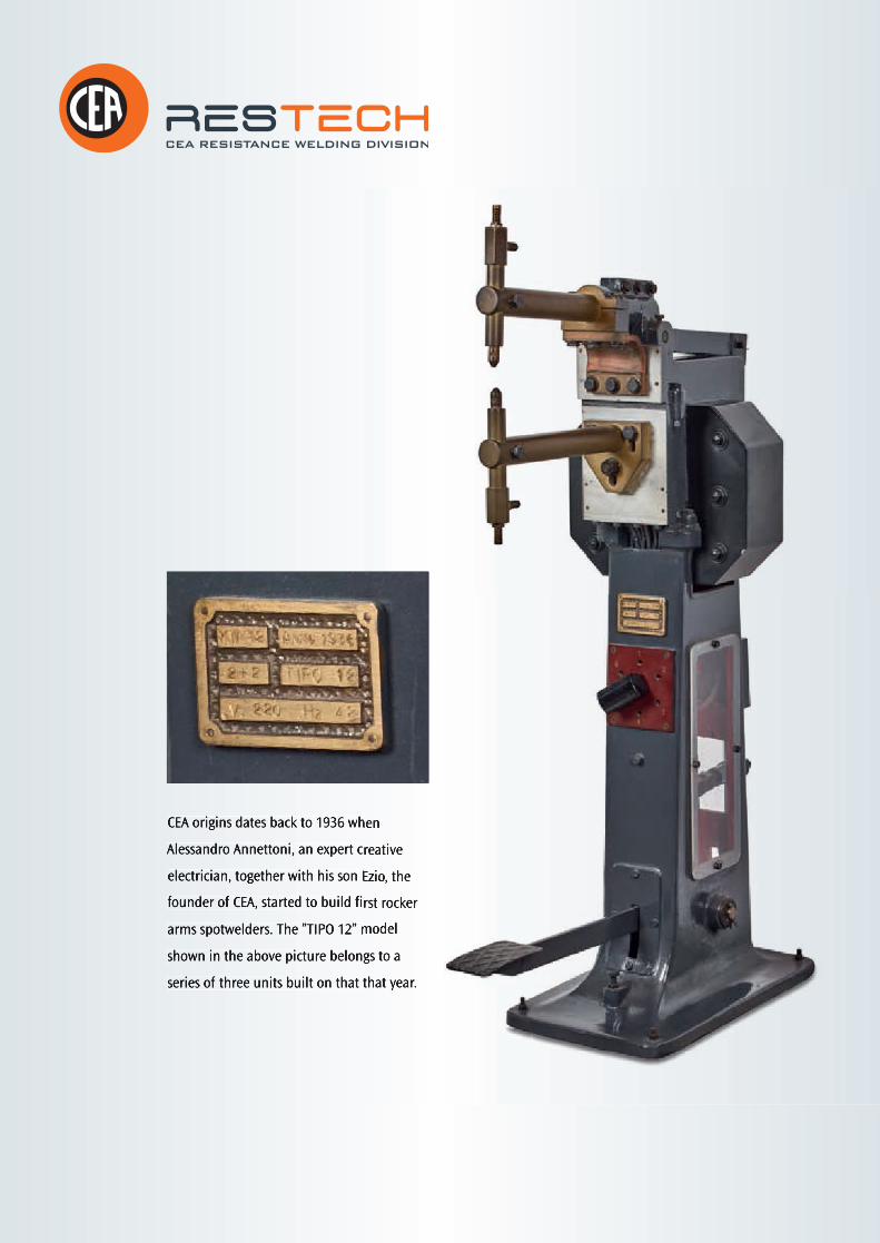
CEA origins dates back to 1936 when CEA origins dates back to 1936 when
Alessandro Annettoni, an expert creative Alessandro Annettoni, an expert creative
electrician, together with his son Ezio, the electrician, together with his son Ezio, the
founder of CEA, started to build first rocker founder of CEA, started to build first rocker
arms spotwelders. The ”TIPO 12” model arms spotwelders. The ”TIPO 12” model
shown in the above picture belongs to a shown in the above picture belongs to a
series of three units built on that that year.series of three units built on that that year.

5WWW.CEAWELD.COM
Z / ZP
K / KP
PPS
PPN
MF
PPN 3F CC
BSW
DUAL
X-GUN / C-GUN
N
SRT - SQ/A
SQ/AS
RT - RL
VOYAGER
CUSTOMIZED EQUIPMENT
ELECTRONIC CONTROLS & COMPONENTS
6
9
12
14
18
24
28
31
32
36
39
40
41
44
48
50

WWW.CEAWELD.COM6
Z / ZP
1
3
Z
2
4
ROCKER ARM SPOT WELDERS WITHADJUSTABLE ARM LENGTH
The Z and ZP series resistance spot welders, versatile, robust and easy-to-use, ensure best welding results on all weldable metals. Thanks to their adjustable length feature they represent the ideal solution in a large variety of spot-welding applications. Z models are mechanical pedal operated, whilst ZP’s are pneumatically operated by an electric pedal.
þþ Excellent welding on all weldable metals
þþ Welding current and time electronic adjustments
þþ Synchronous ignition SCR group with phase shift welding current adjustment to eliminate initial transient
þþ Reduced consumption
þþ Water cooled arms
þþ Water cooled copper electrodeholders with adjustable height
þþ Self-lubricated pneumatic components to eliminate oil deposits and to safeguard the environment from contaminants (ZP)
þþ High versatility thanks to all different possible work configurations
ZP Z
7
I2(A)
F(N)
I1(A)
t(s)
t(s)
t(s)
f
i1
i2
d
a
a e
ed
b
bc1
c2
WWW.CEAWELD.COM
1 2 3
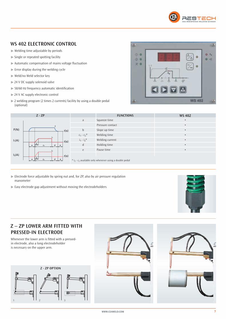
þþ Electrode force adjustable by spring nut and, for ZP, also by air pressure regulation manometer
þþ Easy electrode gap adjustment without moving the electrodeholders
WS 402 ELECTRONIC CONTROLþþ Welding time adjustable by periods
þþ Single or repeated spotting facility
þþ Automatic compensation of mains voltage fluctuation
þþ Error display during the welding cycle
þþ Weld/no Weld selector key
þþ 24 V DC supply solenoid valve
þþ 50/60 Hz frequency automatic identification
þþ 24 V AC supply electronic control
þþ 2 welding program (2 times 2 currents) facility by using a double pedal (optional)
Z – ZP LOWER ARM FITTED WITH PRESSED-IN ELECTRODEWhenever the lower arm is fitted with a pressed-in electrode, also a long electrodeholder is necessary on the upper arm.
Z - ZP
Z - ZP OPTION
FUNCTIONS WS 402a Squeeze time •
Pressure contact •
b Slope up time •
c1 - c2* Welding time •
i1 - i2* Welding current •
d Holding time •
e Pause time •
* i2 - c2 available only whenever using a double pedal

WWW.CEAWELD.COM8
Ø2 Ø1
L1
L2
Electrode for lower arm in pressed-in electrode version
Standard electrode
ACCESSORIES
þþ IR 14 water cooling equipment (for all Z’s and ZP’s)
þþ Special electrodes (on request)
þþ 65 mm offset electrode holders
þþ Long electrode holders
þþ Barholders with 100 mm bars
þþ Possibility of a two-step pedal: squeeze without welding and welding after pressing the second step
þþ Possibility of a double pedal for quick use of two different welding programs
Z 18 Z 28ZP 18 ZP 28
L1 mm 492 492
Ø1 Min mm 60 60
L2 mm 570 570
Ø2 Min mm 85 85
Z - ZP Z 18 Z 28ZP 18 ZP 28
AMIN. mm 250 250MAX. mm 600 600
B mm 215 215C mm 135 135
Ø mm 40 40
Ø mm 21 21
Ø mm 16 16
10% 10%
TECHNICAL DATA Z 18 Z 28ZP 18 ZP 28
Single phase input 50/60 Hz V 400 400
Rated power at 50% kVA 15 25
Max. welding power kVA 23 41,6
Installed power kVA 11 14
Cross section connecting cables mm2 10 10
Delayed fuse A 32 40
Open Circuit Voltage V 2,6 3,5
Short circuit current kA 10,2 13,8
Max. welding current kA 8,2 11
Max. electrode force (6 bar) daN 220 220
Water consumption at 300 kPa (3 bar) l/min 3,8 3,8
Dimensions
mm 760 760
mm 330 330
mm 1200 1200
Weight kg 104 118
Other voltages on request

9
K / KP
1 432
WWW.CEAWELD.COM
The K and KP series resistance spot welders,
versatile, robust and easy-to-use, ensure
best welding results on all weldable metals
and represent the ideal solution in a large
variety of spot-welding applications. K’s
and KP’s allow to adjust lower arm both
in height and also laterally. K models are
mechanical pedal operated, whilst KP’s are
pneumatically operated by an electric pedal.
ROCKER ARM SPOT WELDERS WITH ADJUSTABLE HEIGHT LOWER ARM
þþ Excellent welding on all weldable metals
þþ Welding current and time electronic adjustments
þþ Synchronous ignition SCR group with phase shift welding current adjustment to eliminate initial transient
þþ Reduced consumption
þþ Water cooled arms
þþ Water cooled copper electrodeholders with adjustable height
þþ Self-lubricated pneumatic components to eliminate oil deposits and to safeguard the environment from contaminants (KP)
þþ High versatility thanks to all different possible work configurations
þþ Lower arm with adjustable height which can be rotated for use with a longer electrodeholder (Optional K/KP fig.5)
5 - Optional
K KP
WWW.CEAWELD.COM10
1 2
I2(A)
F(N)
I1(A)
t(s)
t(s)
t(s)
f
i1
i2
d
a
a e
ed
b
bc1
c2
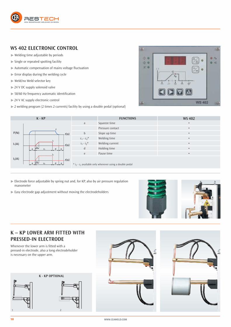
K – KP LOWER ARM FITTED WITH PRESSED-IN ELECTRODEWhenever the lower arm is fitted with a pressed-in electrode, also a long electrodeholder is necessary on the upper arm.
þþ Electrode force adjustable by spring nut and, for KP, also by air pressure regulation manometer
þþ Easy electrode gap adjustment without moving the electrodeholders
WS 402 ELECTRONIC CONTROLþþ Welding time adjustable by periods
þþ Single or repeated spotting facility
þþ Automatic compensation of mains voltage fluctuation
þþ Error display during the welding cycle
þþ Weld/no Weld selector key
þþ 24 V DC supply solenoid valve
þþ 50/60 Hz frequency automatic identification
þþ 24 V AC supply electronic control
þþ 2 welding program (2 times 2 currents) facility by using a double pedal (optional)
K - KP OPTIONAL
K - KP FUNCTIONS WS 402a Squeeze time •
Pressure contact •
b Slope up time •
c1 - c2* Welding time •
i1 - i2* Welding current •
d Holding time •
e Pause time •
* i2 - c2 available only whenever using a double pedal

11WWW.CEAWELD.COM
Ø2Ø3
Ø1
L1L2
L3
ACCESSORIES
þþ IR 14 water cooling equipment (only for K / KP 22 and 28)
þþ Special electrodes (on request)
þþ 65 mm offset electrode holders
þþ Long electrode holders
þþ Barholders with 100 mm bars
þþ Possibility of a two-step pedal: squeeze without welding and welding after pressing the second step
þþ Possibility of a double pedal for quick use of two different welding programs
K - KP K 22 K 28 K 48KP 22 KP 28 KP 48
A mm 455 455 490
A (Optional)mm 600 600 700mm 800 800 1000
BMIN. mm 173 168 163MAX. mm 410 443 438
C mm 255 255 285
Ø mm 40 45 50
Ø mm 21 21 25
Ø mm 16 16 16
10% 10% 10%
TECHNICAL DATA K 22 K 28 K 48KP 22 KP 28 KP 48
Single phase input 50/60 Hz V 400 400 400Rated power at 50% kVA 20 25 45Max. welding power kVA 36,5 54,7 75Installed power kVA 12 14 24Cross section connecting cables mm2 10 16 25Delayed fuse A 25 36 63Open Circuit Voltage V 3,5 4,2 5,2Short circuit current kA 11,6 14 17,8Max. welding current kA 9,3 11,2 14,2Max. electrode force (6 bar) daN 180 220 260Water consumption at 300 kPa (3 bar) l/min 3,8 3,8 3,8
Dimensions mm 980 980 1020þmm 330 390 390 mm 1200 1250 1250
Weight kg 120 167 194
K 22 K 22 K 28 K 28 K 48 K 48 K 48
KP 22 KP 22 KP 28 KP 28 KP 48 KP 48 KP 48
A mm 455 600 455 800 490 700 1000L1 mm 252 397 252 597 257 467 767Ø1 Min mm 60 60 63 63 65 65 65L2 mm 280 429 429 774 295 505 805Ø2 Min mm 85 85 90 90 98 98 98L3 mm 397 542 402 747 427 637 937Ø3 Min mm 180 180 185 185 205 205 205
Other voltages on request

WWW.CEAWELD.COM12
PPS
PPS 125
VERTICAL STROKE SPOT WELDERSPPS models, developed appositely for spot welding jobs, fully satisfy a wide range of the heaviest large production industrial applications. Equipped with a microprocessor control, upon request they can be supplied in special configurations or fitted with an optional safety concomitant push button external unit.
þþ Excellent welding on all weldable metals
þþ Synchronous ignition SCR group with phase shift welding current adjustment to eliminate initial transient
þþ Thermostatic protection on the SCR group
þþ High welding currents with low consumption
þþ Self-lubricated pneumatic components to eliminate oil deposits and to safeguard the environment from contaminants
þþ Water cooled secondary circuit, i.e. electrodes, electrodeholders and transformer, to avoid overheating
þþ Water cooled copper electrodeholders with adjustable height
þþ Electrode force adjustable by pressure reducer group equipped with a manometer and filter for automatic air impurity expulsion
þþ Upper electrode movement by self-lubricated double effect pneumatic cylinder fitted with speed regulator, end stroke shock-absorber and silencer for compressed air discharge
þþ Manual valve for upper head descent without pressure for cleaning, centering and ordinary maintenance of the electrodes
þþ Solenoid valve to control welding cylinder
þþ Cycle stop emergency button
PPS 35 - 60þþ Lower round arm with adjustable height and lateral adjustment
þ Lower arm holder can be adjusted for use with larger arm gap
PPS 125 þþ Upper head low friction driving system for precision welding

13
l
tFK
F(N)
I (A)
t
t
STAR
T
a b d e q p i mg gh
nf
c
WWW.CEAWELD.COM
WS 708 ELECTRONIC CONTROL
OPTIONAL
þÚ Safety concomitant push button external unit (optional)
þÚ Different length arms (optional)
þÚ Lower arms with pressed-in electrode (for entering pipes or boxes) and longer electrodeholder on the upper arm (Optional)
Ú 8 programs Ú Half period welding time Ú Pre-heating current Ú Two 24 V DC solenoid valves Ú 50/60 Hz frequency Ú Mains voltage compensation Ú Error message Ú Weld/no weld switch Ú Single or multi spot
Other voltages on request
Electrode PPS 35/60 Electrode PPS 125
Push button external unit
TECHNICAL DATA PPS35 60 125
Single phase input 50/60 Hz V 400 400 400Rated power at 50% kVA 35 60 125Short circuit power kVA 86 142 368Max. welding power kVA 69 113 294Installed power kVA 20 38 80Cross section connecting cables mm2 25 35 95Delayed fuse A 63 100 250Open Circuit Voltage V 4,5 5,9 11,5Short circuit current kA 19 24 32Max. welding current kA 15,2 19,2 25,6Thermal secondary current at 100% kA 3,9 7,2 7,68Work stroke mm 60 65 100Max. electrode force (6 bar) daN 230 470 900Water consumption at 300 kPa (3 bar) l/min 6 7 8
Dimensionsþmm 1005 1070 1370mm 410 430 420þmm 1425 1520 1750
Weight kg 200 335 700
PPS 35 PPS 60 PPS 125
A mm 395 435 500A (Optional) mm - 650 700
BMIN. mm 140 180 170MAX. mm 400 510 320
CMIN. 690 615 710MAX. 950 945 860
Ø mm 50 60 88
Ø mm 30 35 35
PPS
FUNCTIONS WS 708a Pre-squeeze time •
b Squeeze time •c Pressure contact •d Preheating time •e Cooling time •f Slope up time •g Welding time •
Welding current •h Pulse interval time •i Holding time •l Cycle end contact •
m Pause time •
WWW.CEAWELD.COM14
PPN
14
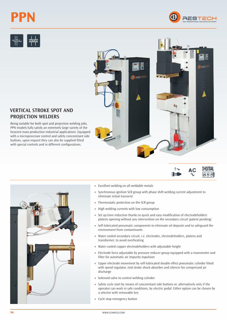
VERTICAL STROKE SPOT AND PROJECTION WELDERSBeing suitable for both spot and projection welding jobs, PPN models fully satisfy an extremely large variety of the heaviest mass production industrial applications. Equipped with a microprocessor control and safety concomitant side buttons, upon request they can also be supplied fitted with special controls and in different configurations.
þÚ Excellent welding on all weldable metals
þÚ Synchronous ignition SCR group with phase shift welding current adjustment to eliminate initial transient
þÚ Thermostatic protection on the SCR group
þÚ High welding currents with low consumption
þÚ Set up time reduction thanks to quick and easy modification of electrodeholders platens opening without any intervention on the secondary circuit (patent pending)
þÚ Self-lubricated pneumatic components to eliminate oil deposits and to safeguard the environment from contaminants
þÚ Water cooled secondary circuit, i.e. electrodes, electrodeholders, platens and transformer, to avoid overheating
þÚ Water cooled copper electrodeholders with adjustable height
þÚ Electrode force adjustable by pressure reducer group equipped with a manometer and filter for automatic air impurity expulsion
þÚ Upper electrode movement by self-lubricated double effect pneumatic cylinder fitted with speed regulator, end stroke shock-absorber and silencer for compressed air discharge
þÚ Solenoid valve to control welding cylinder
þÚ Safety cycle start by means of concomitant side buttons or, alternatively only if the operator can work in safe conditions, by electric pedal. Either option can be chosen by a selector with removable key
þÚ Cycle stop emergency button

1515
A)
C)
A)
C)
B)A)
B)
WWW.CEAWELD.COM
PPN 63THEY ARE EQUIPPED WITH:
þþ Lower round arm with adjustable height and lateral adjustment
þþ Electrodeholders with electrodes for spotwelding and ability to easily fit barholders for projection welding
þþ Lower arm holder can be adjusted for use with larger arm gap
þþ Spotwelding (A)
þþ Projection welding with bars for mesh (B)
UPON REQUEST ALSO AVAILABLE WITH:
þþDifferent length arms (optional)
þþ Lower arms with pressed-in electrode (for entering pipes or boxes) and longer electrodeholder on the upper arm (optional)
þþ Special version with platens only for projection welding (PPN 63) (C)
PPN 83 - 103 - 153 - 253 All supplied with lower platen adjustable in height and fitted with T-slots, enabling the quick assembly of barholders, electrodeholders or any dedicated tooling for a specific application.Platens gap is easily and quickly adjustable without any intervention on the secondary circuit (patent pending).
þþManual valve for upper head descent without pressure for cleaning, centering and ordinary maintenance of the electrodes
þþUpper head low friction driving system for precision welding (except PPN 83)
A) Spotwelding
B) Barholder welding for mesh
C) Projection welding

WWW.CEAWELD.COM16
WS 708 WS 3000 AC FILIUS MULTI
J J
J J J
J J J
J J J
J J J
J J J
J J J
J J J
J J J
J J J
J J J
J J J
J J J
J J
J J
J J J
J J J
J J J
8 100 32
J J
J J
J
J J J
J J J
J J
J J J
J J J
CUSTOMIZED VERSIONS
ELECTRONIC CONTROLSFUNCTIONS
Pre-squeeze time
Squeeze time
Preheating time
Preheating current
Cooling time
Slope up
Welding time
Welding current
½ period welding time
Welding time 2 (2 pedal version)
Welding current 2 (2 pedal version)
Pulse interval time
Pulse number
Post heating time
Post heating current
Holding time
Pause time
Auto-repeat
Program no.
Welding current display
Limit monitoring
Constant current
Mains voltage compensation
Error message
Spot counter
Pressure contact
Cycle end contact
17WWW.CEAWELD.COM
Other voltages on request
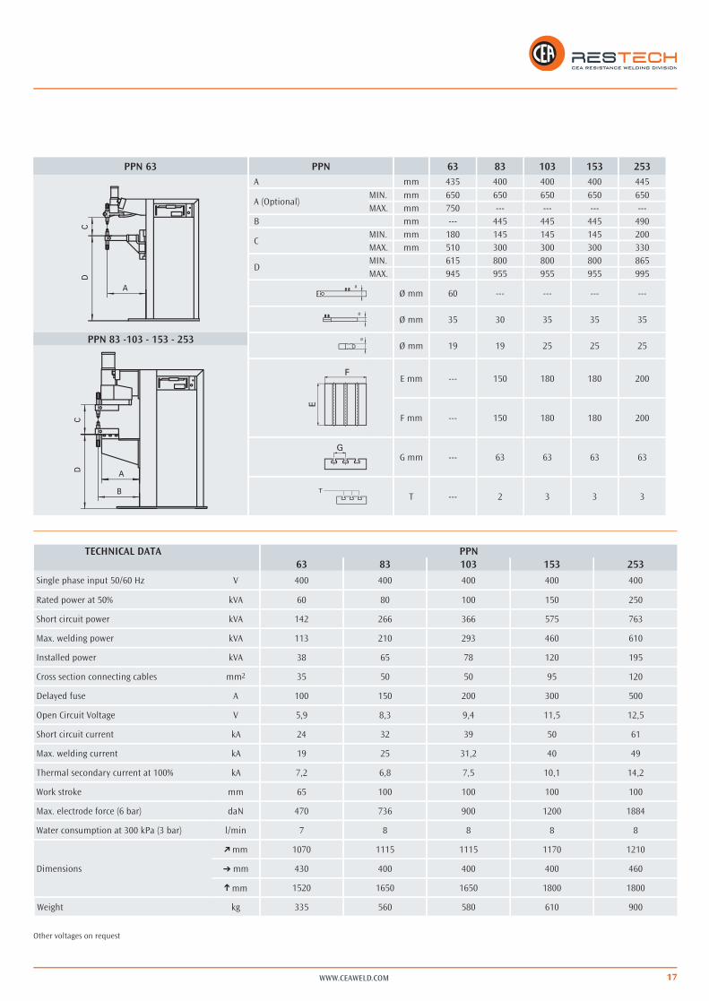
PPN 63
PPN 83 -103 - 153 - 253
PPN 63 83 103 153 253A mm 435 400 400 400 445
A (Optional)MIN. mm 650 650 650 650 650MAX. mm 750 --- --- --- ---
B mm --- 445 445 445 490
CMIN. mm 180 145 145 145 200MAX. mm 510 300 300 300 330
DMIN. 615 800 800 800 865MAX. 945 955 955 955 995
Ø mm 60 --- --- --- ---
Ø mm 35 30 35 35 35
Ø mm 19 19 25 25 25
E mm --- 150 180 180 200
F mm --- 150 180 180 200
G mm --- 63 63 63 63
T --- 2 3 3 3
TECHNICAL DATA PPN63 83 103 153 253
Single phase input 50/60 Hz V 400 400 400 400 400
Rated power at 50% kVA 60 80 100 150 250
Short circuit power kVA 142 266 366 575 763
Max. welding power kVA 113 210 293 460 610
Installed power kVA 38 65 78 120 195
Cross section connecting cables mm2 35 50 50 95 120
Delayed fuse A 100 150 200 300 500
Open Circuit Voltage V 5,9 8,3 9,4 11,5 12,5
Short circuit current kA 24 32 39 50 61
Max. welding current kA 19 25 31,2 40 49
Thermal secondary current at 100% kA 7,2 6,8 7,5 10,1 14,2
Work stroke mm 65 100 100 100 100
Max. electrode force (6 bar) daN 470 736 900 1200 1884
Water consumption at 300 kPa (3 bar) l/min 7 8 8 8 8
Dimensions
þmm 1070 1115 1115 1170 1210
þmm 430 400 400 400 460
þmm 1520 1650 1650 1800 1800
Weight kg 335 560 580 610 900

18
MF
WWW.CEAWELD.COM
þþ All MF equipment can be converted into bench version types (BSW) or utilized in seamwelding applications too.
þþ High welding quality and process reliability
þþ Direct current welding
þþ Large power for welding with increased arm lengths
þþ Possibility of monitoring the welding process each 1ms (1000 Hz) or even each 0,2 ms with MF5040 versus 20 ms of traditional 50 Hz equipment.
þþ The presence of magnetic materials between the arms does not affect welding
þþ Self-lubricated pneumatic components to eliminate oil deposits and to safeguard the environment from contaminants
þþ Water cooled secondary circuit
þþ Low tendency for welding spatters
þþ Less imprint and deformation
þþ Very long electrode life
RESISTANCE MEDIUM FREQUENCYTHREE PHASE SPOT/PROJECTION WELDERS
The MF range of medium-frequency inverter resistance welders is the ultimate answer to increasing demand for quality in resistance welding applications.Constant current control, fast millisecond current regulation, high quality and perfect control of the energy transferred to the weld nugget are the main advantages versus traditional 50 Hz equipment. MF models fully meet the toughest mass production industrial applications. Thanks to their features, they represent the ideal solution for resistance spot welding of thin thickness and of hardly weldable material, such as copper, brass, alluminium alloys, zinc plated and other coated steel.
19
ms
C PPN
MF
WeldQ
Q = - Q Q in
Q in
out
Q out
Q out
Q out
Weld
0 2 4 6 8 10 12 ms14
0
5
7,5
kA
10
C
PPN3FCCMFkA
ms
d
1286 10 kA
8
mm6
5
4
MF
PPN
PPN3FCC
d
0,8 mm
=
~
400V 3~50/60Hz 500V
1000Hz
-%
+%
kA
WWW.CEAWELD.COM
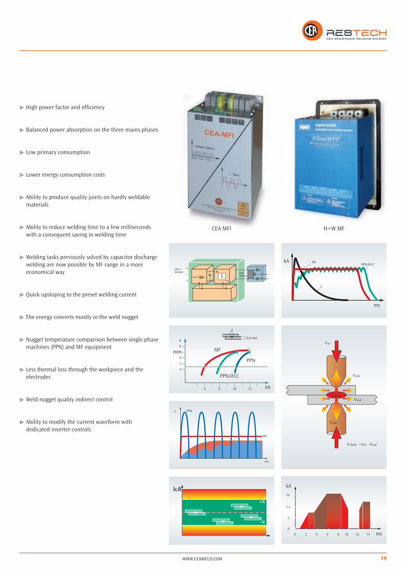
þþ High power factor and efficiency
þþ Balanced power absorption on the three mains phases
þþ Low primary consumption
þþ Lower energy consumption costs
þþ Ability to produce quality joints on hardly weldable materials
þþ Ability to reduce welding time to a few milliseconds with a consequent saving in welding time
þþ Welding tasks previously solved by capacitor discharge welding are now possible by MF range in a more economical way
þþ Quick upsloping to the preset welding current
þþ The energy converts mostly in the weld nugget
þþ Nugget temperature comparison between single phase machines (PPN) and MF equipment
þþ Less thermal loss through the workpiece and the electrodes
þþ Weld nugget quality indirect control
þþ Ability to modify the current waveform with dedicated inverter controls
H+W MFCEA MFI

20 WWW.CEAWELD.COM
MF 1040 - MF 1041 - MF 5020The most enhanced inverter technology for medium frequency spotwelding available for everyone. These equipment , fitted with new inverters with WSI 100 or WS 3000 MF or FILIUS COMPACT controls, represent a valid solution for anybody looking for all Medium Frequency benefits in both spotwelding applications and nut projection welding too.
MF 1040 and 1041 models allow to monitor the whole welding process every 1 ms (1000 Hz).
The far faster MF 5020, whose inverter operates at 5000 Hz, are able to even control the process every 0.2 ms.
þ Lower round arm with adjustable height and lateral adjustment
þþ Electrodeholders with electrodes for spotwelding
þ Lower arm can be lowered and adjusted for use with larger arm gap
UPON REQUEST ALSO AVAILABLE WITH:
þ Different length arms (optional)
þþ Lower arms with pressed-in electrode (for entering pipes or boxes) and longer electrodeholder on the upper arm (optional)
Electrodeholder set
Offset electrode holder set Barholder sets with bars
Standard Electrode
Concomitant push button unit

21
A) B)
Max. 56
WWW.CEAWELD.COM
MF 100 - MF 160 - MF 200Medium frequency (1000 Hz) MF 100 - 160 - 200 are particularly suitable for projection welding applications requiring high welding current and force and also for spotwelding special material and alloys to be joined with elevated currents and short welding time.
þ High power spot and projection welding
þþ Lower platen adjustable in height and fitted, like the upper one, with T-slots, enabling the quick assembly of barholders, electrodeholders or any dedicated tooling for specific applications
þ Platens gap is easily and quickly adjustable without any intervention on the secondary circuit
þþ Safety cycle start by means of concomitant side buttons or, as alternative only if the operator can work in safe conditions, by electric pedal. Either option can be chosen by a selector with removable key
þ Upper head linear low friction driving system for very precise welding
þþ Manual valve for upper head descent without pressure for cleaning, centering and ordinary maintenance of the electrodes
þ Solenoid valve to stop water circulation whenever the machine is switched off from the mains supply
REMOTE CONTROL BY PERSONAL COMPUTER (B)
þþ Network up to 56 machinesþþ 128 programsþþ Constant current facilityþþ Limit current monitoringþþ Preheating currentþþ Annealing currentþþ Linearized stepper functionþþ Two 24 V DC solenoid valvesþþ Proportional valve
þþ Production monitoringþþ Error message logbookþþ Weld counterþþ Mains voltage compensationþþ Single or multi spot þþ Stored data filesþþ Back up fileþþ Operating parameter software
INTEGRATED CONTROL PANEL (A)
þþ 64/128 programsþþ Constant current facilityþþ Limit current monitoringþþ Preheating currentþþ Annealing currentþþ Linearized stepper functionþþ Two 24 V DC solenoid valvesþþ Proportional valveþþ Weld/no weld switchþþ Error message logbookþþ Weld counterþþ Main voltage compensationþþ Single or multi spotþþ Liquid crystal display

22 WWW.CEAWELD.COM
FUNCTIONS
Pre-squeeze time
Squeeze time
Preheating time
Preheating current
Cooling time
Slope up
Welding time
Welding current
Welding time adjustable in ms
Welding time 2 (2 pedal version)
Welding current 2 (2 pedal version)
Pulse interval time
Pulse number
Post heating time
Post heating current
Holding time
Pause time
Auto-repeat
Program no.
Welding current display
Limit monitoring
Constant current
Mains voltage compensation
Error message
Spot counter
Pressure contact
Cycle end contact
WSI 100 WS 3000 MFFILIUS MF
CLASSIC
J J
J J J
J J J
J J J
J J J
J J J
J J J
J J J
J J J
J J J
J J J
J J J
J J J
J J J
J J J
J J J
J J J
J J J
64 100 128
J J J
J J J
J J J
J J J
J J J
J J J
J J J
J J J

23WWW.CEAWELD.COM
Other voltages on request
TECHNICAL DATA MF1040 1041 5020 100 160 200
Three phase input 50/60 Hz V 400 400 400 400 400 400
Rated power at 50% kVA 40 40 20 100 160 200
Installed power kVA 40 40 40 50 70 100
Cross section connecting cables mm2 35 35 35 35 50 70
Delayed fuse A 63 63 63 63 100 160
Open Circuit Voltage V 5,0 5,0 11,5 10 10 12
Short circuit current kA 22 22 16 28 45 55
Max. welding current kA 20 20 14 23 36 44
Thermal secondary current at 100% kA 5,4 5,4 --- 6,5 12,0 12,0
Work stroke mm 65 65 65 100 100 100
Max. electrode force 600 kPa (6 bar) daN 470 470 470 900 1200 1800
Water consumption at 300 kPa (3 bar) l/min 6 6 6 20 20 20
Dimensions
þmm 1070 1070 1070 1115 1115 1210
þmm 430 430 430 400 400 460
þmm 1520 1520 1520 1650 1650 1800
Weight kg 260 260 255 530 550 850
MF 1040 - 1041 - 5020
MF 100 - 160 - 200
1040 1041 5020 100 160 200A mm 435 435 435 400 400 445
A (Optional)mm 650 650 650 650 650 650mm 750 750 750 --- --- ---
B mm --- --- --- 445 445 490
CMIN. mm 180 180 180 145 145 200MAX. mm 510 510 510 300 300 330
DMIN. mm 615 615 615 800 800 865MAX. mm 945 945 945 955 955 995
Ø mm 60 60 60 --- --- ---
Ø mm 35 35 35 30 35 35
Ø mm 19 19 19 25 25 25
E mm --- --- --- 180 180 200
F mm --- --- --- 180 180 200
G mm --- --- --- 63 63 63
T --- --- --- 3 3 3
MF

WWW.CEAWELD.COM24
PPN 3F CC
DIRECT CURRENT
þþ High quality joints
þþ Large power for projection welding
þþ Large power for welding with increased arm lengths
þþ The presence of magnetic materials between the arms does not affect welding
þþ Long electrode life
þþ Highest efficiency
þþ Reduced welding time
3-PHASE MAINS SUPPLY
þþ Balanced power absorption on the three mains phases
þþ Low primary consumption
þþ High power factor and output
þþ Lower cost for electric power
þþ Water cooled secondary circuit to avoid electrical parts overheating
þþ Self-lubricated pneumatic components to eliminate oil deposits and to safeguard the environment from contaminants
þþ Safety cycle start by means of concomitant side buttons or, as alternative only if the operator can work in safe conditions, by electric pedal. Either option can be chosen by a selector with removable key
þþ Cycle stop emergency button
þþ All the machines are supplied with lower platen adjustable in height and fitted with T-slots, enabling the quick assembly of barholders, electrodeholders or any dedicated tooling for each application
DIRECT CURRENT THREE PHASE RESISTANCE SPOT/PROJECTION WELDERSSuitable for both spot and projection welding, PPN 3F CC models fully meet the most sophisticated and toughest mass production industrial applications. Thanks to their features, they represent the ideal solution for resistance spot welding of aluminium and other material not easily weldable by conventional resistance equipment. Equipped with microprocessor control, concomitant safety side buttons and solenoid valve, upon request, they can be supplied with special controls in various configurations.

25
A)
B) C)
WWW.CEAWELD.COM
þþ Platens gap is easily and quickly adjustable without any intervention on the secondary circuit (patent pending)
þþ Upper head low friction linear driving system for very precise welding
þþ Manual valve for upper head descent without pressure for cleaning, centering and ordinary maintenance of the electrodes
þþ Solenoid valve to stop water circulation whenever the machine is switched off from the mains supply
þþ Suitable for applications requiring high welding power, such as mesh welding
þþ High welding quality and process reliability
þþ Synchronous ignition SCR group with phase shift welding current adjustment to eliminate initial transient
þþ Thermostatic protection on the SCR group
þþ Six phase rectifier bridge with diodes protected against overheating and overvoltage
OPTIONAL AND SPECIAL VERSIONS
A. Adjustable double stroke cylinder
B. Double set of concomitant side buttons and double pedal for 2 program welding cycles
C. Welding program quick selector
þþ Flowmeter stopping the welding process in case of insufficient water flow
þþ Two step pedal for squeeze without welding and welding after pushing the second step
þþ 0,5 bar low pressure solenoid valve for applications requiring so
þþ Proportional valve to select and control two pressure levels

WWW.CEAWELD.COM26
A) B)
l
tFK
F(N)
I (A)
t
t
STAR
T
a b d e q p i mg gh
nf
c
Max. 56
REMOTE CONTROL BY PERSONAL COMPUTER (B)
þþ Network up to 56 machinesþþ 64 programsþþ Constant current facilityþþ Limit current monitoringþþ Preheating currentþþ Annealing currentþþ Linearized stepper functionþþ Two 24 V DC solenoid valvesþþ Proportional valve
þþ Production monitoringþþ Error message logbookþþ Weld counterþþ Mains voltage compensationþþ Single or multi spot þþ Stored data filesþþ Back up fileþþ Operating parameter software
INTEGRATED CONTROL PANEL (A)
þþ 32 / 64 programsþþ Constant current facilityþþ Limit current monitoringþþ Preheating currentþþ Annealing currentþþ Linearized stepper functionþþ Two 24 V DC solenoid valvesþþ Proportional valveþþ Weld/no weld switchþþ Error message logbookþþ Weld counterþþ Main voltage compensationþþ Single or multi spotþþ Liquid crystal display
FUNCTIONS A - Ba Pre-squeeze time •
b Squeeze time •
c Pressure contact •
d Preheating time •
e Cooling time •
f Slope up time •
g Welding time •
h Pulse interval time •
n Slope down time •
q Cooling time •
p Annealing time •
i Holding time •
l Cycle end contact •
m Pause time •

27WWW.CEAWELD.COM
PPN 100 3F CC
PPN 160 - 260 - 360 - 460 3F CC
PPN 3F CC 100 160 260 360 460A mm 500 445 445 445 445A (Optional) mm 700 650 650 650 650B mm --- 490 490 490 490
CMIN. mm 235 200 200 200 250MAX. mm 390 330 332 350 400
DMIN. mm 900 852 852 900 942MAX. mm 1055 982 982 1050 1092
Ø mm 88 --- --- --- ---
Ø mm 35 --- --- --- ---
Ø mm 25 --- --- --- ---
E mm --- 200 200 250 250
F mm --- 200 200 250 250
G mm --- 63 63 63 63
T --- 3 3 4 4
TECHNICAL DATA
Three phase input 50/60 Hz
Rated power at 50%
Power at 100%
Short circuit power
Max. welding power
Cross section connecting cables
Delayed fuse
Open Circuit Voltage
Short circuit current
Max. welding current
Work stroke
Max. electrode force 600 kPa (6 bar)
Water consumption at 300 kPa (3 bar)
Dimensions
Weight
PPN 3F CC100 160 260 360 460
V 400 400 400 400 400
kVA 100 160 250 350 450
kVA 71 113 177 247 318
kVA 560 716 878 1350 2200
kVA 448 572 702 1080 1760
mm2 50 70 95 120 2 x 120
A 160 200 250 300 400
V 6,3 6,8 8 8,8 10
kA 60 72 90 106 140
kA 48 58 72 85 112
mm 100 100 100 100 100
daN 900 1200 1880 2400 3600
l/min 20 20 20 20 25
mm 1480 1540 1540 1610 1610
mm 430 480 480 530 530
mm 1800 1890 1890 2170 2300
kg 1100 1210 1300 1410 1800
Other voltages on request

WWW.CEAWELD.COM28
BSW
VERTICAL STROKE SPOT AND PROJECTION BENCH WELDERS BSW bench welders, thanks to their reduced dimensions, are suitable to build customised multispot welding equipment.BSW 25 is particularly suitable for precision spot welding and,fitted with special accessories, can be used to weld small size parts.BSW 50 and 100, thanks to their rigid structure, allow high quality projection welding.
þUpper head low friction driving system for very precise and quality welding
þþ Secondary circuit low impedance to grant high welding currents with low consumption
þBSW 50 and 100, with a platens adjustable in height and fitted with T-slots, enable the quick assembly of barholders, electrodeholders and any dedicated tooling for a specific application
þþ Safety cycle start by means of concomitant side buttons or, as alternative only if the operator can work in safe conditions, by electric pedal. Either option can be chosen by a selector with removable key
þ Cycle stop emergency button

29WWW.CEAWELD.COM
ELECTRONIC CONTROLSFUNCTIONS
Pre-squeeze time
Squeeze time
Preheating time
Preheating current
Cooling time
Slope up
Welding time
Welding current
½ period welding time
Welding time 2 (2 pedal version)
Welding current 2 (2 pedal version)
Pulse interval time
Pulse number
Post heating time
Post heating current
Holding time
Pause time
Auto-repeat
Program no.
Welding current display
Limit monitoring
Constant current
Mains voltage compensation
Error message
Spot counter
Pressure contact
Cycle end contact
OPTIONAL
þÚ Double pedal for the 2 time 2 current feature on the same workpiece
þÚ Adjustable double stroke cylinder
þÚ Barholder set with bars þÚ Two step pedal for squeeze without welding and welding after pushing the second step
þÚ 0,5 bar low pressure solenoid valve for applications requiring so
WS 708 WS 3000 AC FILIUS MULTI
J J
J J J
J J J
J J J
J J J
J J J
J J J
J J J
J J J
J J J
J J J
J J J
J J J
J J
J J
J J J
J J J
J J J
8 100 32
J J
J J
J
J J J
J J J
J J
J J J
J J J

WWW.CEAWELD.COM30
Other voltages on request
Electrode BSW 25 Electrode BSW 50 Electrode BSW 100
BSW 25
BSW 50 - 100
BSW 25 50 100A mm 200 400 335B mm --- 305 370
CMIN. mm --- 100 140MAX. mm 135 225 290
DMIN. mm --- 140 175MAX. mm 135 265 325
Ø mm 40 --- ---
Ø mm 18 25 30
Ø mm 16 16 19
E mm --- 90 150
F mm --- 130 150
G mm --- 45 63
T --- 2 2
TECHNICAL DATA BSW25 50 100
Single phase input 50/60 Hz V 400 400 400
Rated power at 50% kVA 25 50 100
Short circuit power kVA 65 160 414
Max. welding power kVA 52 128 331
Installed power kVA 14 38 78
Cross section connecting cables mm2 16 25 50
Delayed fuse A 40 100 200
Open Circuit Voltage V 3,7 5,5 9,4
Short circuit current kA 18 29 45
Max. welding current kA 14,4 23,2 36
Thermal secondary current at 100% kA 4,8 6,4 7,5
Work stroke mm 50 75 100
Max. electrode force (6 bar) daN 187 470 900
Water consumption at 300 kPa (3 bar) l/min 4 7 7
Dimensions
þmm 800 900 1080
þmm 300 300 325
þmm 590 770 1015
Weight kg 96 210 380

DUAL
40÷180 mm
31WWW.CEAWELD.COM
TWIN SPOT WELDING UNITThe twin spot welding units are the most suitable solution for single side welding and they ensure the possibility to realise multi spot welding equipment in a simple and economical way. Each twin spot unit is fitted with its own welding control, thus allowing independent operation or, by connecting more units together, the operator can weld either in electric or pneumatic cascade or simultaneously.
PUSH-PULL
The “push-pull” system allows to operate on thicker thickness; it’s obtained, as shown in the left picture, by connecting a special version of DUAL 30 to another opposite unit without any control.
Other voltages on request
TECHNICAL DATA DUAL 30
Single phase input 50/60 Hz V 400
Rated power at 50% kVA 30
Max. welding power kVA 96
Installed power kVA 20
Delayed fuse A 63
Open Circuit Voltage V 6
Short circuit current kA 20
Max. welding current kA 16
Work stroke mm 60
Distance between electrodes mm 40 - 180
Max. electrode force (6 bar) daN 2 x 180
Water consumption at 300 kPa (3 bar) l/min 4
Dimensions
mm 380
mm 162
mm 630
Weight kg 68

WWW.CEAWELD.COM32
X-GUN / C-GUN
þþ Welding control in a separate cabinet with circuit breaker with residual current device and cycle stop emergency button
þþ Synchronous ignition SCR group with phase shift welding current adjustment to eliminate initial transient
þþ Reduced consumption
þþ Water cooled transformer
þþ Water cooled arms, electrode holders and electrodes
þþ Gyroscope suspension on sealed bearings for easy gun rotation and manoeuvrability in any position
þþ Adjustable working stroke
þþ Temporary extra stroke to easily reach workpiece areas also getting over obstacles
þþ High versatility in all applications thanks to all possible configurations
þþ Self-lubricated pneumatic components to eliminate oil deposits and to safeguard the environment from contaminants
SPOT WELDING GUNS WITH BUILT-IN TRANSFORMERThe X-Gun and C-Gun series pneumatic operated suspended guns, versatile, robust and easy-to-use, ensure best welding results on any weldable metal and are the most ideal solution for any spotwelding job.
C-GUN
X-GUN

33
176
146
250
950
400
220
340
230
280
330
650
90ø 20
425
60590ø 3
0
L1
Ø 20
150
Ø 32
L 26
Ø16Ø14
34
L1
Ø 32
L
150
Ø 20
WWW.CEAWELD.COM
C-GUN
X-GUN
Both straight (version 1) and angled(version 2) arms are availablein a large variety and different lengths from 200 up to 600 mm.
1. Electrode force at 600 kPa (6bar)
2. Arm set weight
3. Welding stroke
4. Temporary extra stroke
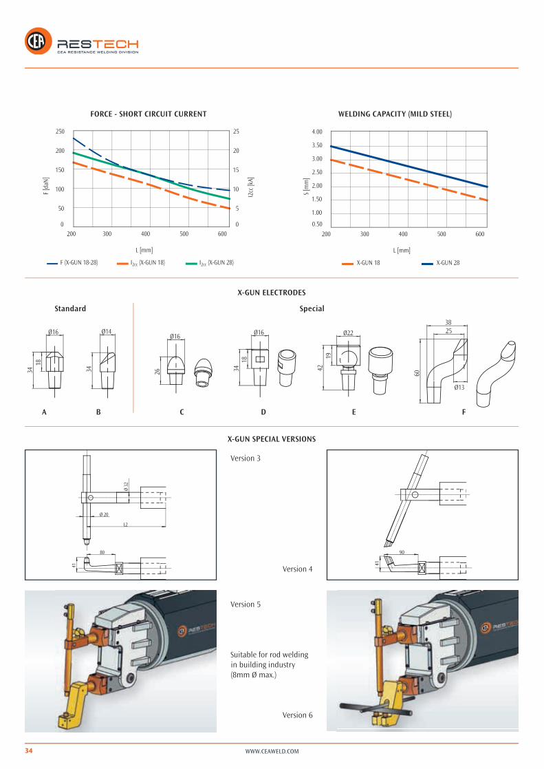
X-GUN VERSION 1L (mm) 220 300 400 500 600L1 (mm) 155 235 335 435 535(1) F (daN) 230 170 135 110 95(2) P (kg) 2,7 3,5 4,6 5,7 6,7(3) Cs (mm) 0-24 0-30 0-38 0-46 0-55(4) CI (mm) 57 73 93 112 131
X-GUN VERSION 2L (mm) 220 300 400 500 600L1 (mm) 155 235 335 435 535(1) F (daN) 230 170 135 110 95(2) P (kg) 2,7 3,5 4,6 5,7 6,7(3) Cs (mm) 0-24 0-30 0-38 0-46 0-55(4) CI (mm) 57 73 93 112 131
WWW.CEAWELD.COM34
I2cc (X-GUN 18) I2cc (X-GUN 28)F (X-GUN 18-28)
L [mm]I2
cc [k
A]
F [d
aN]
5
10
15
20
25
00
250
200
150
100
50
600500400300200
4.00
3.50
3.00
2.50
2.00
1.50
200 300 400 500 600
0.50
1.00
S [m
m]
L [mm]
X-GUN 28X-GUN 18
2538
Ø13
60
Ø2219
423418
Ø16
26
Ø16Ø14
34
1834
Ø16
80
41
Ø 20
Ø 32
L2
90
41
A B C D E F
FORCE - SHORT CIRCUIT CURRENT
X-GUN ELECTRODES
X-GUN SPECIAL VERSIONS
WELDING CAPACITY (MILD STEEL)
SpecialStandard
Version 3
Version 4
Version 5
Suitable for rod welding in building industry (8mm Ø max.)
Version 6

35
l
tFK
F(N)
I (A)
t
t
STAR
T
a b d e q p i mg gh
nf
c
WWW.CEAWELD.COM
WS 708 WELDING CONTROL
þþ Half period welding time
þþ Single or multi spot
þþ Mains voltage automatic compensation
þþ 2 programs retrievable from the handle switch selector
þþ 8 programs to be activated and used from the control keyboar
þþ Error messages
þþ Weld/no weld switch
þþ 24 V DC solenoid valve
þþ 50/60 Hz frequency automatic recognition
þþ 24 V AC mains supply for the control
ACCESSORIES
þ Gun spring balancer
þþ Reducer with filter and manometer
Other voltages on request
TECHNICAL DATA X-GUN C-GUN18 28 28
Single phase input 50/60 Hz V 400 400 400Rated power at 50% kVA 18 28 28Max. welding power kVA 58 88 98Installed power kVA 15 25 25Delayed fuse A 32 40 40Open Circuit Voltage V 4,8 5,8 5,8Short circuit current kA 15 19 21Max. welding current kA 12 15,2 16,8Work stroke mm 50 50 50 + 20Max. electrode force (6 bar) daN 230 230 300Water consumption at 300 kPa (3 bar) l/min 4 4 4
Dimensions mm 650 650 800þmm 250 250 250 mm 425 425 425
Weight kg 47 53 58
FUNCTIONS WS 708
a Pre-squeeze time •
b Squeeze time •
c Pressure contact •
d Preheating time •
e Cooling time •
f Slope up time •
g Welding time •
Welding current •
h Pulse interval time •
i Holding time •
l Cycle end contact •
m Pause time •

WWW.CEAWELD.COM36
N 3 (C)
N 22 (B)
N
BUTT WELDERS FOR WIRE DRAWING MILLSN 3, N 9, N 12 and N 22 butt welders have been particularly designed for wire drawing mills for joining steel, brass, aluminium and copper rods and are suitable for all low-cadence applications. All models are available with annealing facility.Jaws opening and closing is by means of foot pedals only in N 9, whilst it is operated by manual levers in N 3, N 12 and N 22.
N 3, N 9 and N 12 are standard supplied with a 4 wheel trolley for easy manoeuvrability, whilst N 22, on request, may be supplied with optional transport wheels.
Upon request all models of the N series can be supplied with a burr-removing grinding wheel. Lighted magnifying glass is additionally available for N 3 only.
þþ Manually operated
þþ Welding upset adjustment
þþ Welding power adjustment
þþ Movable jaw by bearing guides
þþ Graduated scale to easily adjust jaws opening (N 3, N 9 and N 12)
þþ Electronic control for welding parameter adjustment (N 22)
OPTIONAL
þÚ Grinding wheel with magneto-thermal switch and blackout safety protection device ( see A on next page and B)
þÚ Four wheel trolley for N 22 (see B)
þÚ Lighted magnifying glass for N 3 ( see C)
N 12N 3 N 9

37
(A)
WWW.CEAWELD.COM
SPECIAL VERSIONS
þþ Vertical up wire welding (N/I 22 VERT)
Other voltages on request
N/I 22 VERT
N 3 N 9 N 12 N 22min max min max min max min max
Fe● ø mm 0,5 2,5 0,8 8 2 14 3 18
■ mm2 4,9 50 150 250
CrNi● ø mm 0,5 1,2 0,8 6 2 9 3 16
■ mm2 1,1 28 65 200
Al● ø mm 0,8 2 2 5 2 8 4 12
■ mm2 3,1 20 50 110
Cu● ø mm 0,5 1,8 1,5 3,5 2 6 4 8
■ mm2 2,5 10 28 50
CuZn● ø mm 0,5 1,8 1,5 3,5 2 6 4 14
■ mm2 2,5 10 28 150
TECHNICAL DATA N 3 N 9 N 12 N 22
Single phase input 50/60 Hz V 400 400 400 400
Rated power at 50% kVA 0,8 3 4 20
Max. welding power kVA 2 9,6 18 93
Installed power kVA 1 3 4 15
Cross section connecting cables mm2 2,5 2,5 2,5 16
Delayed fuse A 10 10 10 40
Open Circuit Voltage V 2 2,6 2,4 4,2
Short circuit current kA 1,2 4,4 10 28
Clamping force daN 10 80 200 1000
Upsetting force daN 1,3 20 80 300
Max. welding capacity on mild steel mm2 4,9 50 150 250
Wire diameterMIN. mm 0,5 0,8 2 3
MAX. mm 2,5 8 14 18
Dimensions
þmm 518 565 770 800
þmm 515 565 660 600
þmm 1145 1100 1120 1550
Weight kg 52 80 80 280
Grinding wheel
N 22
N 20
38 WWW.CEAWELD.COM
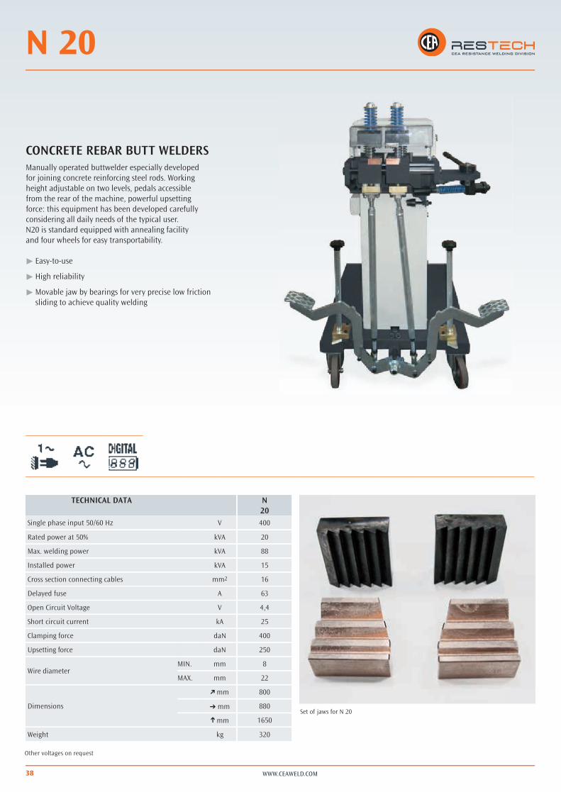
CONCRETE REBAR BUTT WELDERSManually operated buttwelder especially developed for joining concrete reinforcing steel rods. Working height adjustable on two levels, pedals accessible from the rear of the machine, powerful upsetting force: this equipment has been developed carefully considering all daily needs of the typical user. N20 is standard equipped with annealing facility and four wheels for easy transportability.
þþ Easy-to-use
þþ High reliability
þþ Movable jaw by bearings for very precise low friction sliding to achieve quality welding
Other voltages on request
TECHNICAL DATA N20
Single phase input 50/60 Hz V 400
Rated power at 50% kVA 20
Max. welding power kVA 88
Installed power kVA 15
Cross section connecting cables mm2 16
Delayed fuse A 63
Open Circuit Voltage V 4,4
Short circuit current kA 25
Clamping force daN 400
Upsetting force daN 250
Wire diameterMIN. mm 8
MAX. mm 22
Dimensions
þmm 800
mm 880
þmm 1650
Weight kg 320
Set of jaws for N 20

SRT - SQ/A
WWW.CEAWELD.COM 39
MASS PRODUCTION BUTT WELDERSSRT and SQ/A butt welders, air operated with completely automatic cycle, allow high productivity and are suitable for welding wire-manufactured goods. SRT 11, due to its welding speed, is particularly recommended for high-cadence applications. SRT and SQ/A equipment, being fitted with welding controls with the pulse facility, enable to obtain much better finishing joints, slightly expanded with reduced burr.
þþ Air operated
þþ Electronic control for adjusting the welding parameters
þþ Movable jaw by bearing guides
Other voltages on request
SQ/A 62
TECHNICAL DATA SRT SQ/A SQ/A SQ/A11 121 62 100
Single phase input 50/60 Hz V 400 400 400 400
Rated power at 50% kVA 4 25 60 100
Max. welding power kVA 18 122 168 350
Installed power kVA 4 15 80 120
Cross section connecting cables mm2 2,5 16 70 95
Delayed fuse A 10 40 200 300
Open Circuit Voltage V 2,2 5,1 6 10,8
Short circuit current kA 10 30 35 40
Clamping force daN 150 900 3000 5150
Upsetting force daN 58 350 1800 2400
Max. welding capacity on mild steel mm2 50 200 450 620
Wire diameterMIN. mm 1,5 3 6 6
MAX. mm 8 16 24 28
Dimensions
þmm 620 830 850 850
mm 600 640 1750 1750
þmm 1100 1460 1900 2100
Weight kg 84 280 1200 1300
SQ/A 121SRT 11

WWW.CEAWELD.COM
SQ / AS
40
FLASH BUTT WELDERSSQ/AS models are suitable for flash butt welding solid material, profiles and hollow sections and mostly pipes, whenever water tight joints are needed, by obtaining very high quality welding results. Particularly suitable for mass production with fully automatic controls aiding speed and efficiency.
SQ/AS machines start the welding operationby slowly approaching, at a reduced pressure,the two parts to be joined; when they are close one another, an electric arc strikes between them and, in a very short time, they are brought toa pre-melting condition; at this point the two ends,in a semi-solid status, are heavily pressed oneagainst the other by the upsetting force. This will result into a totally impurity-free high quality joint.
þþ Easy-to-use
þ Air operated
þþ Electronic control for adjusting the welding parameters
þ Movable jaw by bearing guides
Other voltages on request
TECHNCAL DATA SQ/AS SQ/AS SQ/AS121 62 100
Single phase input 50/60 Hz V 400 400 400
Rated power at 50% kVA 25 60 100
Max. welding power kVA 122 168 350
Installed power kVA 15 60 100
Cross section connecting cables mm2 16 70 95
Delayed fuse A 40 160 250
Open Circuit Voltage V 5,1 6 10,8
Short circuit current kA 30 35 40
Clamping force daN 1350 1400 5150
Upsetting force daN 450 900 2400
Max. welding capacity on mild steel mm2 250 350 550
Wire diametermm 5 8 8
mm 16 20 26
Dimensions
þmm 830 850 850
þmm 920 1700 1750
þmm 1600 1900 2100
Weight kg 300 1200 1300
SQ/AS 62SQ/AS 121

41WWW.CEAWELD.COM
RT / RL
41WWW.CEAWELD.COM
WWW.CEAWELD.COM
RT / RL
42
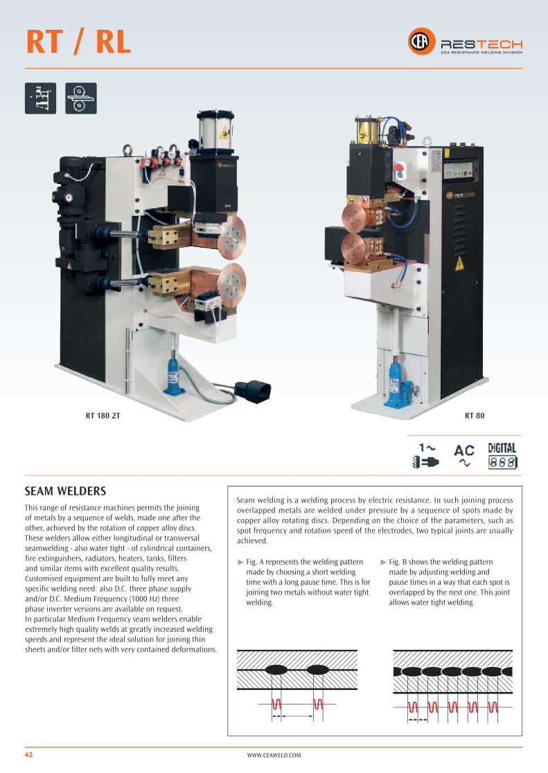
SEAM WELDERSThis range of resistance machines permits the joining of metals by a sequence of welds, made one after the other, achieved by the rotation of copper alloy discs.These welders allow either longitudinal or transversal seamwelding - also water tight - of cylindrical containers, fire extinguishers, radiators, heaters, tanks, filters and similar items with excellent quality results.Customised equipment are built to fully meet any specific welding need: also D.C. three phase supply and/or D.C. Medium Frequency (1000 Hz) three phase inverter versions are available on request.In particular Medium Frequency seam welders enable extremely high quality welds at greatly increased welding speeds and represent the ideal solution for joining thin sheets and/or filter nets with very contained deformations.
Seam welding is a welding process by electric resistance. In such joining process overlapped metals are welded under pressure by a sequence of spots made by copper alloy rotating discs. Depending on the choice of the parameters, such as spot frequency and rotation speed of the electrodes, two typical joints are usually achieved.
þþ Fig. A represents the welding pattern made by choosing a short welding time with a long pause time. This is for joining two metals without water tight welding.
þþ Fig. B shows the welding pattern made by adjusting welding and pause times in a way that each spot is overlapped by the next one. This joint allows water tight welding.
RT 80RT 180 2T

43
90
RT
RL
WWW.CEAWELD.COM
þþ RT version for transversal welding only
þþ RL version for longitudinal welding only
þþ Water cooled seam heads with silver contacts, ensuring a good current transmission from the static part to the shaft
þþ Reduced maintenance costs
þþ Self-lubricated pneumatic components to eliminate oil deposits and to safeguard the environment from contaminants
þþ Frequency converter to adjust the welding speed of the discs
Other voltages on request
TECHNICAL DATA RT RL80 80 2T 81 180 2T 81
Single phase input 50/60 Hz V 400 400 400 400 400Rated power at 50% kVA 60 60 80 180 80Installed power kVA 60 60 80 180 80Delayed fuse A 150 150 200 400 200Open Circuit Voltage V 5,1 5,1 6,7 9,5 6,7Arm length mm 450 450 800 450 800Work stroke mm 80 80 80 100 80Max. disc force 600 kPa (6 bar) daN 470 470 470 1200 470Water consumption at 300 kPa (3 bar) l/min 6 6 6 7 6Welding speed m/min 0,6 - 4,2 0,6 - 4,2 0,6 - 4,2 0,8 + 5 0,6 - 4,2Max. welding capacity on mild steel mm 1,2 + 1,2 1,2 + 1,2 1,2 + 1,2 2 + 2 1,2 + 1,2Max. welding capacity on stainless steel mm 1,5 + 1,5 1,5 + 1,5 1,5 + 1,5 3 + 3 1,5 + 1,5
Dimensions mm 1150 1150 1450 1450 1450 mm 800 800 800 800 800 mm 2020 2020 2100 2100 2100
Weight kg 800 800 900 1540 900Drive head A A + B B A + B BDriving system C E D E DDrive headA = lowerB = upperDriving systemC = toothed beltD = direct with Hooke’s jointE = Differential
WWW.CEAWELD.COM
VOYAGER
44
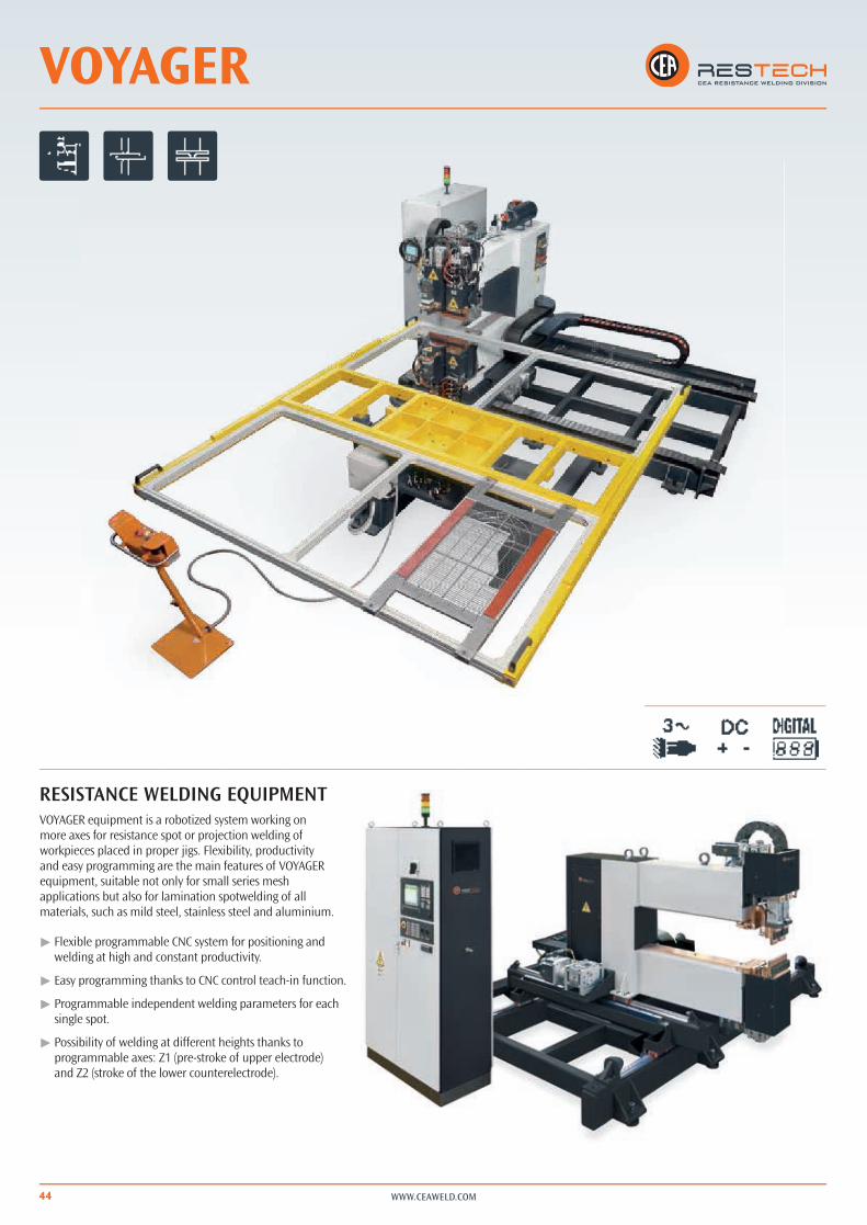
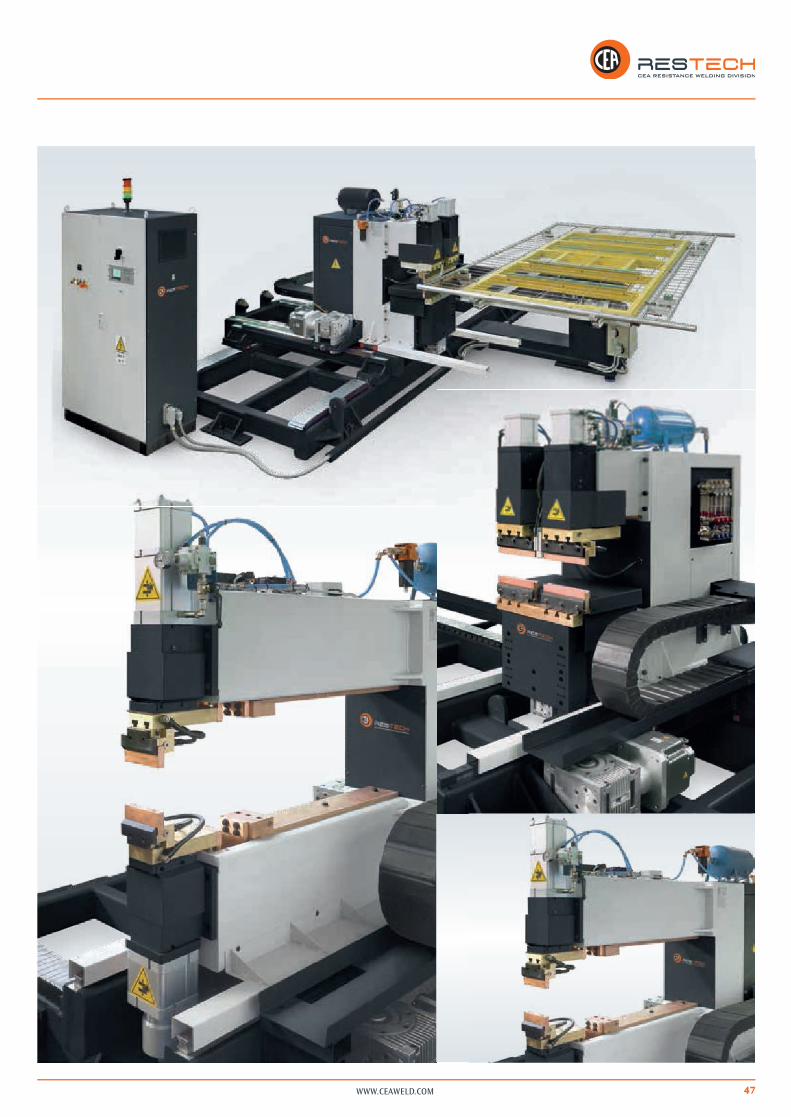
RESISTANCE WELDING EQUIPMENT VOYAGER equipment is a robotized system working on more axes for resistance spot or projection welding of workpieces placed in proper jigs. Flexibility, productivity and easy programming are the main features of VOYAGER equipment, suitable not only for small series mesh applications but also for lamination spotwelding of all materials, such as mild steel, stainless steel and aluminium.
þþ Flexible programmable CNC system for positioning and welding at high and constant productivity.
þþ Easy programming thanks to CNC control teach-in function.
þþ Programmable independent welding parameters for each single spot.
þþ Possibility of welding at different heights thanks to programmable axes: Z1 (pre-stroke of upper electrode) and Z2 (stroke of the lower counterelectrode).
45
Y
Z1
Z2
X
C1
C2
WWW.CEAWELD.COM
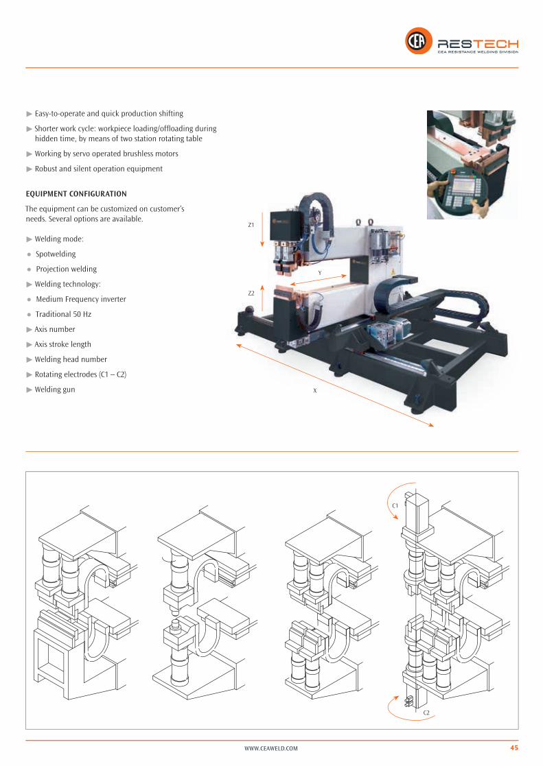
þþ Easy-to-operate and quick production shifting
þþ Shorter work cycle: workpiece loading/offloading during hidden time, by means of two station rotating table
þþ Working by servo operated brushless motors
þþ Robust and silent operation equipment
EQUIPMENT CONFIGURATION
The equipment can be customized on customer’s needs. Several options are available.
þþ Welding mode:
þÚ Spotwelding
þÚ Projection welding
þþ Welding technology:
þÚ Medium Frequency inverter
þÚ Traditional 50 Hz
þþ Axis number
þþ Axis stroke length
þþ Welding head number
þþ Rotating electrodes (C1 – C2)
þþ Welding gun

WWW.CEAWELD.COM46
5500
5500
Z1=
100
Z2 =
50
4700 X=
2000
þþ Handheld remote control unit
OPTIONAL
þÚ Operator panel for program monitoring and job storing
Other version on request
47WWW.CEAWELD.COM

WWW.CEAWELD.COM48
CEA also designs and manufactures special resistance machines, either fully automated or developed as purpose-built fully customized special versions. According to specific requirements from the clients and on the basis of the quoted drawings of the components to be welded, CEA resistance engineers are able to propose the best solutions most suiting any need of resistance equipment or automation.
CUSTOMIZED EQUIPMENT

49WWW.CEAWELD.COM

50 WWW.CEAWELD.COM
WS 402 WS 708
FILIUSWS 3000 AC
CEA RESTECH new catalogue offers a complete range of electronic controls and component kits suitable for integrators, special machine manufacturers and also for any retrofit job to upgrade any old generation resistance equipment. The resistance specialists will be able to find a really large variety of components for single phase, three phase and latest generation inverter based technologies with related electronic controls, power panels and transformers able to fully meet any industrial needs.
50 HZ COMPONENT KIT
50 HZ TRANSFORMERS
DESCRIPTION Sn U2 I2P
ACT 63 63 kVA 7,1 V 6,3 kAACT 100 100 kVA 10,0 V 7,1 kAACT 125 125 kVA 11,1 V 8,0 kAACT 150 150 kVA 13,1 V 8,1 kAACT 200 200 kVA 10,5 V 13,5 kAACT 250 250 kVA 12,1 V 14,6 kA
Sn= rated power at 50% U2= open circuit voltage
I2P= permanent thermal current
ELECTRONIC CONTROLS AND COMPONENTS
ACT TRANSFORMERS

51WWW.CEAWELD.COM
406 100 ms 5% 14 kA 12 kA408 100 ms 5% 14 kA 20 kA413 100 ms 5% 14 kA 20 kA 30 kA416 100 ms 5% 20 kA 35 kA 36 kA424 100 ms 5% 35 kA 36 kA
Sn U2
MFT 40 40 kVA 5,0 VMFT 75 75 kVA 8,4 VMFT 100 100 kVA 10,0 VMFT 170 170 kVA 10,0 VMFT 200 200 kVA 12,0 V
CEA MFI
H + W MF
H + W MF
MFT
MFT
MFT
WSI 100
FILIUS
WS 3000 MF
MEDIUM FREQUENCY KITS
1KHZ MEDIUM FREQUENCY TRANSFORMERS
I2 = welding current @ = duty cycle WT = max. welding time
MF POWER UNIT WT @MEDIUM FREQUENCY TRANSFORMERS
MFT 40 MFT 75 MFT 100 MFT 170 MFT 200
DESCRIPTION
Sn = rated power at 50% U2 = open circuit voltage

CEA Costruzioni Elettromeccaniche Annettoni S.p.A.C.so E. Filiberto, 27 23900 LECCO - ITALY Cas. Post. (P.O. BOX) 205Tel. +39 0341 22322 Fax +39 0341 [email protected]
Technical characteristics mightchange without notice.
ConceptValentina Gilardi BEAND
PrintArti Grafiche Cattaneo - Oggiono
Printed in September 2017
© CEA Costruzioni Elettromeccaniche Annettoni S.P.A. September 2017