Embed Size (px)
Citation preview
NUS July 12-14, 2005 Analysis and Design for Robustness of Offshore StructuresNUS – Keppel Short Course
1
Resistance to Accidental Ship Collisions
NUS July 12-14, 2005 Analysis and Design for Robustness of Offshore StructuresNUS – Keppel Short Course
2
OutlineGeneral principlesImpact scenariosImpact energy distributionExternal impact mechanicsCollision forcesEnergy dissipation in local dentingEnergy dissipation in tubular membersStrength of connectionsGlobal integrity
NUS July 12-14, 2005 Analysis and Design for Robustness of Offshore StructuresNUS – Keppel Short Course
3
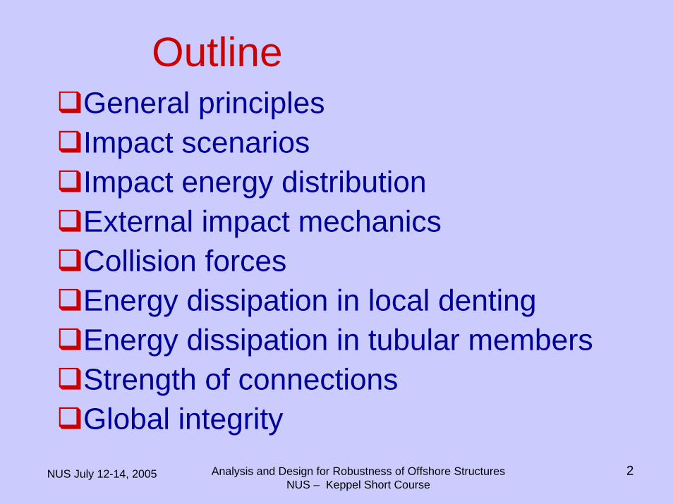
DESIGN AGAINST ACCIDENTAL LOADS
• Verification methods– Simplified (“back of the envelope methods)
• Elastic-plastic/rigid plastic methods (collision/explosion/dropped objects)
• Component analysis (Fire)
– General calculation/Nonlinear FE methods• USFOS, ABAQUS, DYNA3D…..
NUS July 12-14, 2005 Analysis and Design for Robustness of Offshore StructuresNUS – Keppel Short Course
4
• General
– “The inherent uncertainty of the frequency and magnitude of the accidental loads as well as the approximate nature of the methods for their determination as well as the analysis of accidental load effects shall be recognised. It is therefore essential to apply sound engineering judgement and pragmatic evaluations in the design.”
NORSOK STANDARDDESIGN AGAINST ACCIDENTAL LOADS
NUS July 12-14, 2005 Analysis and Design for Robustness of Offshore StructuresNUS – Keppel Short Course
5
NORSOK STANDARDDESIGN AGAINST ACCIDENTAL LOADS
• “If non-linear, dynamic finite element analysis is applied all effects described in the following shall either be implicitly covered by the modelling adopted or subjected to special considerations, whenever relevant”
NUS July 12-14, 2005 Analysis and Design for Robustness of Offshore StructuresNUS – Keppel Short Course
6
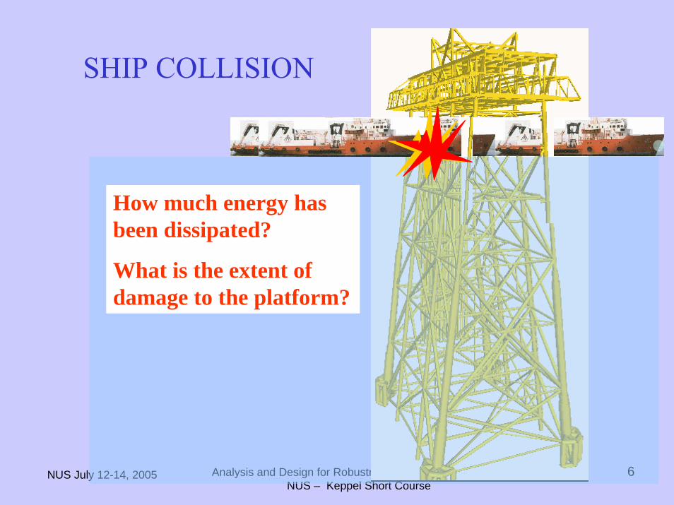
How much energy has been dissipated?
What is the extent of damage to the platform?
SHIP COLLISION
NUS July 12-14, 2005 Analysis and Design for Robustness of Offshore StructuresNUS – Keppel Short Course
7
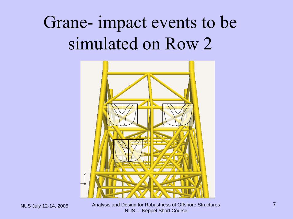
Grane- impact events to be simulated on Row 2
NUS July 12-14, 2005 Analysis and Design for Robustness of Offshore StructuresNUS – Keppel Short Course
8
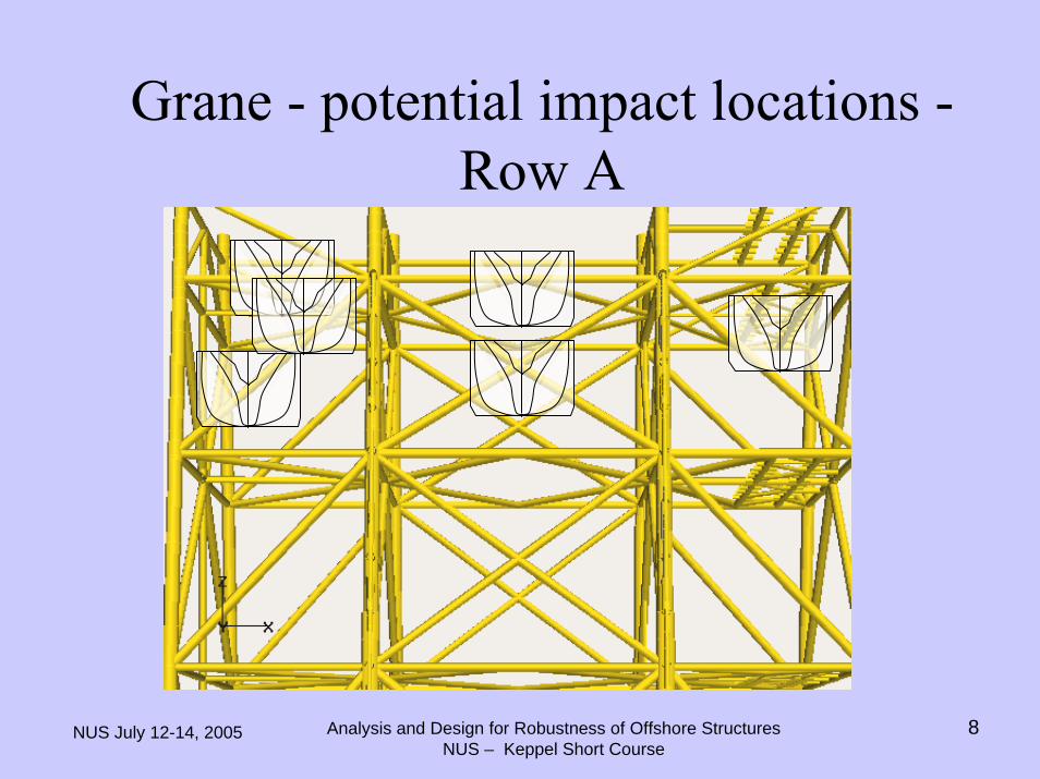
Grane - potential impact locations -Row A
NUS July 12-14, 2005 Analysis and Design for Robustness of Offshore StructuresNUS – Keppel Short Course
9
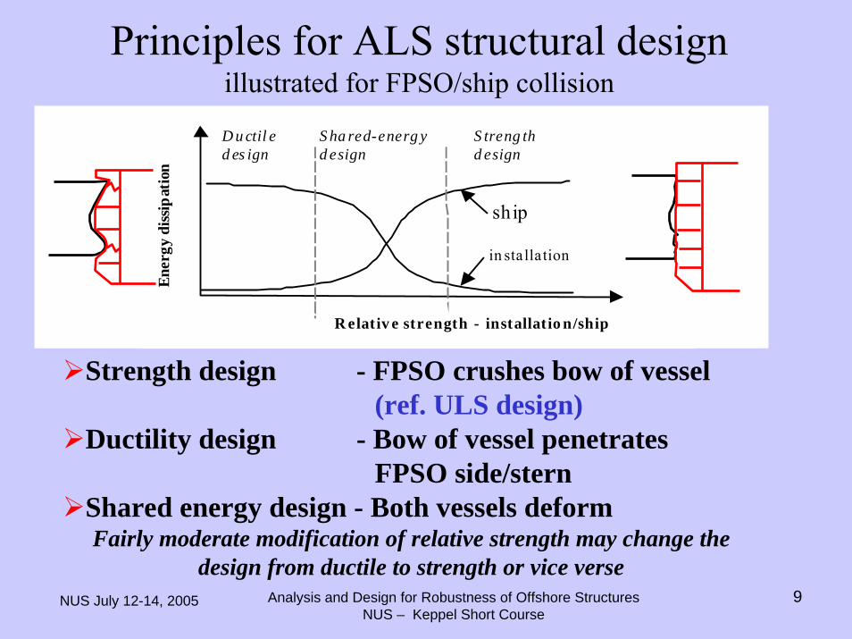
Principles for ALS structural designillustrated for FPSO/ship collision
S treng thd esign
S ha red-energ yd esign
D u ctil ed es ign
R elativ e strength - installatio n/ship
ship
in stallation
Ener
gy d
issip
atio
n
Strength design - FPSO crushes bow of vessel (ref. ULS design)
Ductility design - Bow of vessel penetrates FPSO side/stern
Shared energy design - Both vessels deformFairly moderate modification of relative strength may change the
design from ductile to strength or vice verse
NUS July 12-14, 2005 Analysis and Design for Robustness of Offshore StructuresNUS – Keppel Short Course
10
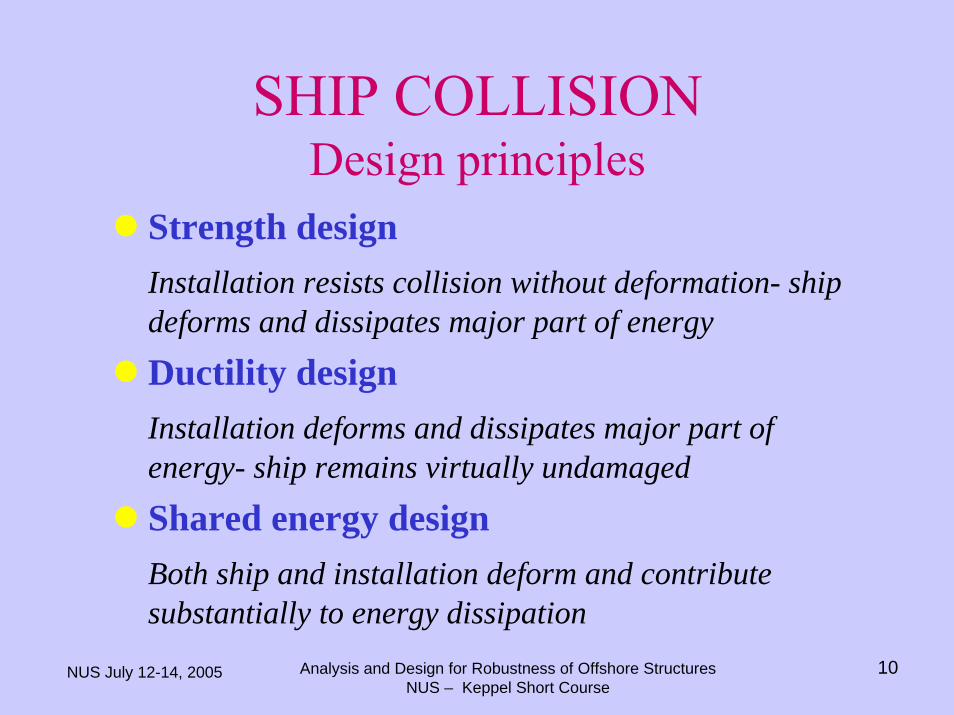
SHIP COLLISIONDesign principles
Strength designInstallation resists collision without deformation- ship deforms and dissipates major part of energy
Ductility designInstallation deforms and dissipates major part of energy- ship remains virtually undamaged
Shared energy designBoth ship and installation deform and contributesubstantially to energy dissipation
NUS July 12-14, 2005 Analysis and Design for Robustness of Offshore StructuresNUS – Keppel Short Course
11
SHIP COLLISIONDesign principles- analysis approach
Strength design:The installation shape governs the deformation field of the ship. This deformation field is used to calculate total and local concentrations of contact force due to crushing of ship.The installation is then designed to resist total and local forces.
Note analogy with ULS design.
NUS July 12-14, 2005 Analysis and Design for Robustness of Offshore StructuresNUS – Keppel Short Course
12
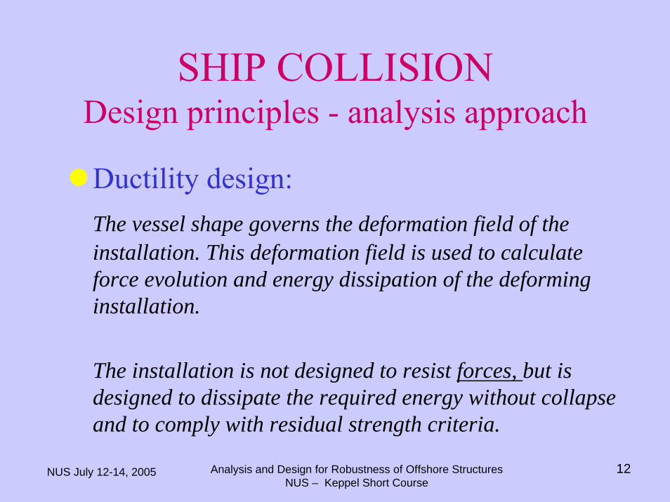
SHIP COLLISIONDesign principles - analysis approach
Ductility design:The vessel shape governs the deformation field of the installation. This deformation field is used to calculate force evolution and energy dissipation of the deforming installation.
The installation is not designed to resist forces, but is designed to dissipate the required energy without collapse and to comply with residual strength criteria.
NUS July 12-14, 2005 Analysis and Design for Robustness of Offshore StructuresNUS – Keppel Short Course
13
SHIP COLLISIONDesign principles - analysis approach
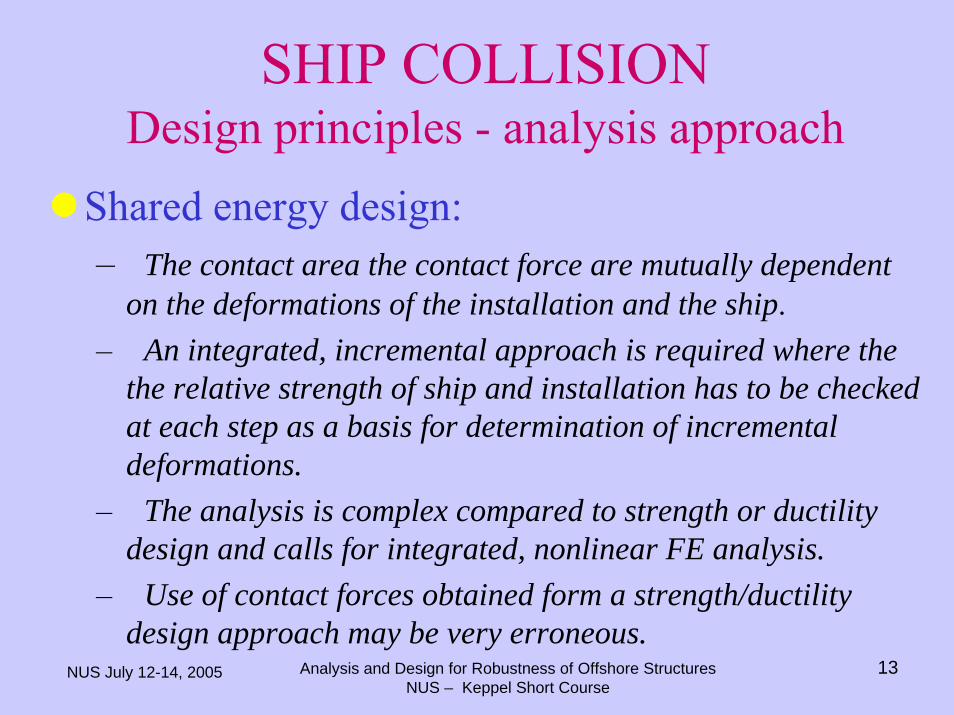
Shared energy design:– The contact area the contact force are mutually dependent
on the deformations of the installation and the ship.– An integrated, incremental approach is required where the
the relative strength of ship and installation has to be checkedat each step as a basis for determination of incremental deformations.
– The analysis is complex compared to strength or ductility design and calls for integrated, nonlinear FE analysis.
– Use of contact forces obtained form a strength/ductility design approach may be very erroneous.
NUS July 12-14, 2005 Analysis and Design for Robustness of Offshore StructuresNUS – Keppel Short Course
14
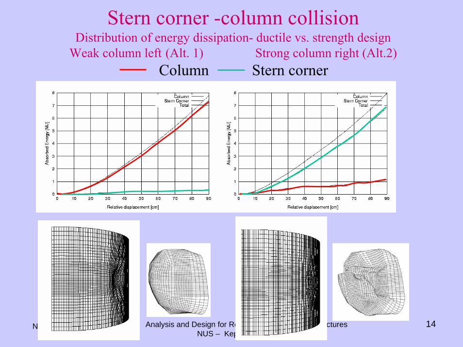
Stern corner -column collisionDistribution of energy dissipation- ductile vs. strength design
Weak column left (Alt. 1) Strong column right (Alt.2)Column Stern corner
NUS July 12-14, 2005 Analysis and Design for Robustness of Offshore StructuresNUS – Keppel Short Course
15
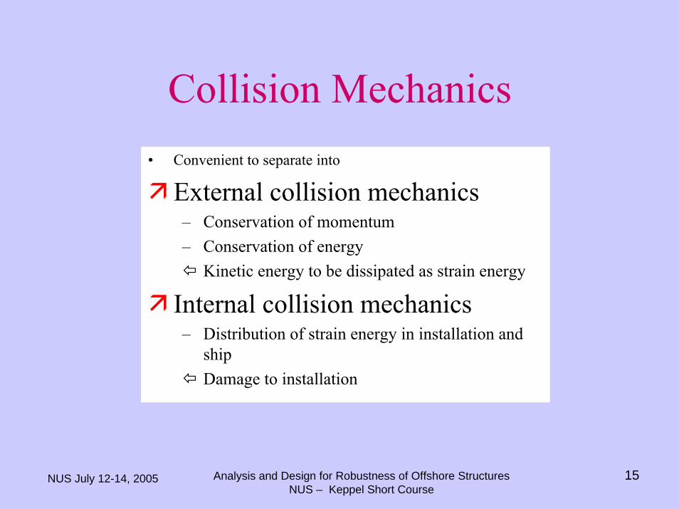
Collision Mechanics• Convenient to separate into
External collision mechanics– Conservation of momentum– Conservation of energy
Kinetic energy to be dissipated as strain energy
Internal collision mechanics– Distribution of strain energy in installation and
shipDamage to installation
NUS July 12-14, 2005 Analysis and Design for Robustness of Offshore StructuresNUS – Keppel Short Course
16
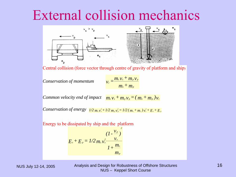
External collision mechanics
Central collision (force vector through centre of gravity of platform and ship)
Conservation of momentumm+m
vm+vm=vps
ppssc
Common velocity end of impact v)m+m( = vm + vm cpsppss
Conservation of energy E + E + v )m+m( 1/2=vm 1/2 + vm 1/2 ps2ccs
2pp
2ss
Energy to be dissipated by ship and the platform
mm+1
)vv-(1
vm1/2=E+E
p
s
s
p2
2ssps
NUS July 12-14, 2005 Analysis and Design for Robustness of Offshore StructuresNUS – Keppel Short Course
17
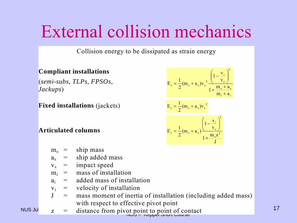
External collision mechanicsCollision energy to be dissipated as strain energy
Compliant installations(semi-subs, TLPs, FPSOs,Jackups)
ii
ss
2
s
i
2ssss
amam1
vv1
)va(m21E
++
+
⎟⎟⎠
⎞⎜⎜⎝
⎛−
+=
Fixed installations (jackets) 2ssss )va(m
21E +=
Articulated columns
Jzm1
vv1
)a(m21E 2
s
2
s
i
sss
+
⎟⎟⎠
⎞⎜⎜⎝
⎛−
+=
ms = ship massas = ship added massvs = impact speedmi = mass of installationai = added mass of installationvi = velocity of installationJ = mass moment of inertia of installation (including added mass)
with respect to effective pivot pointz = distance from pivot point to point of contact
NUS July 12-14, 2005 Analysis and Design for Robustness of Offshore StructuresNUS – Keppel Short Course
18
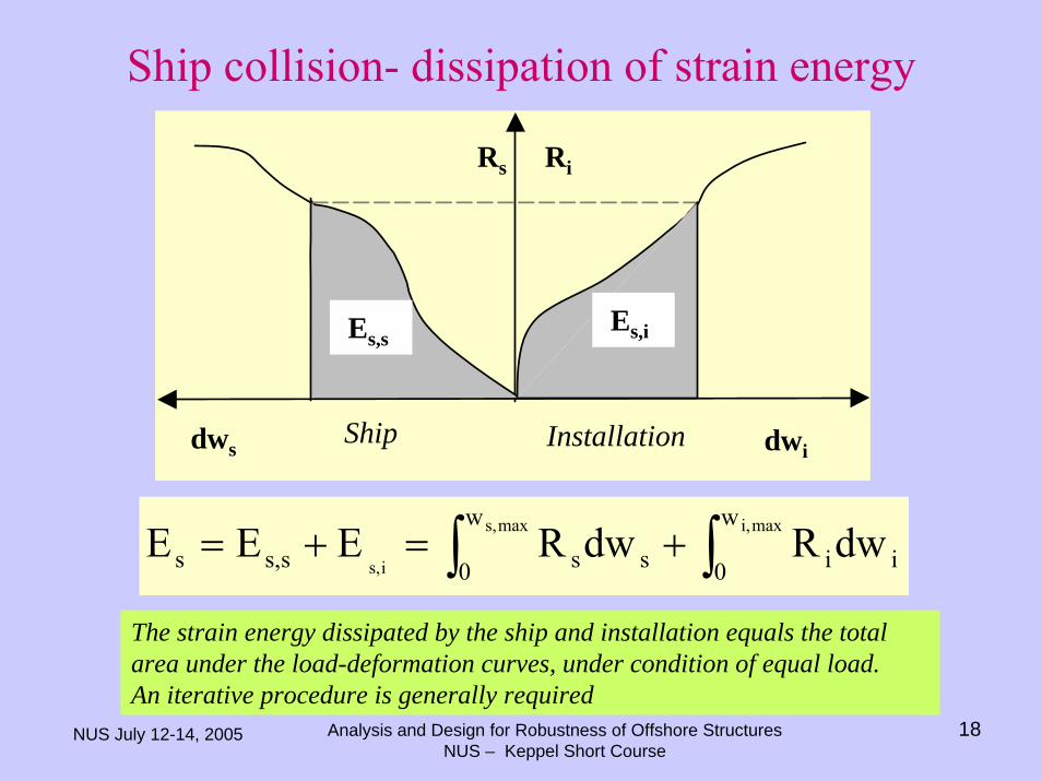
Ship collision- dissipation of strain energy
dws dwi
RiRs
Ship Installation
Es,sEs,i
∫∫ +=+= maxi,maxs,
is,
w
0 ii
w
0 ssss,s dwRdwREEE
The strain energy dissipated by the ship and installation equals the total area under the load-deformation curves, under condition of equal load. An iterative procedure is generally required
NUS July 12-14, 2005 Analysis and Design for Robustness of Offshore StructuresNUS – Keppel Short Course
19
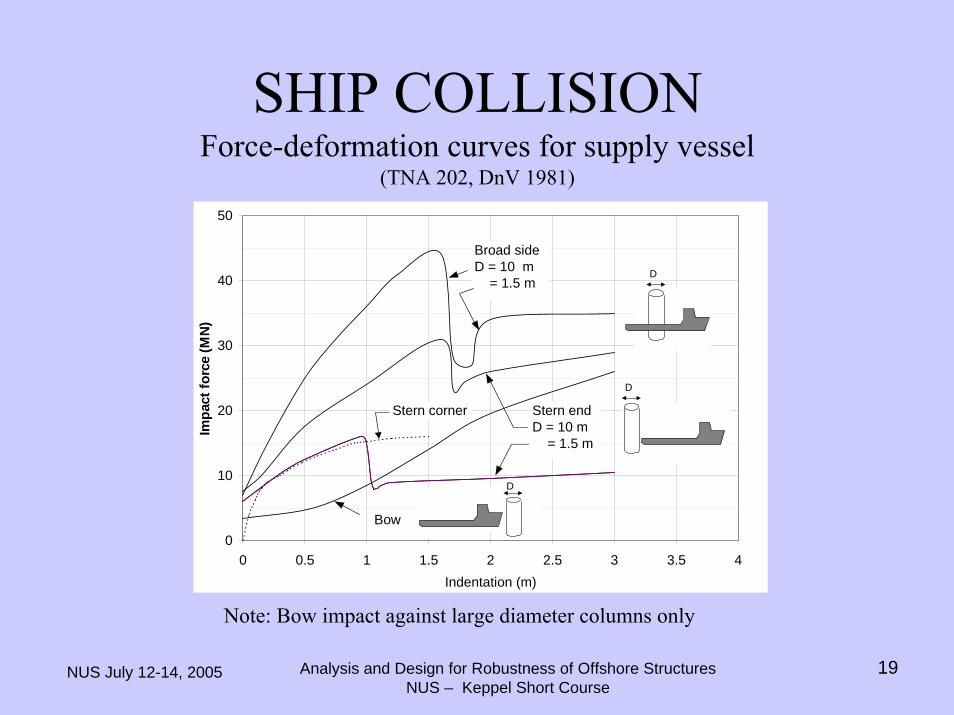
SHIP COLLISIONForce-deformation curves for supply vessel
(TNA 202, DnV 1981)
Note: Bow impact against large diameter columns only
0
10
20
30
40
50
0 0.5 1 1.5 2 2.5 3 3.5 4Indentation (m)
Impa
ct fo
rce
(MN
)
Broad sideD = 10 m = 1.5 m
Stern end D = 10 m = 1.5 m
Bow
Stern corner
D
D
D
NUS July 12-14, 2005 Analysis and Design for Robustness of Offshore StructuresNUS – Keppel Short Course
20
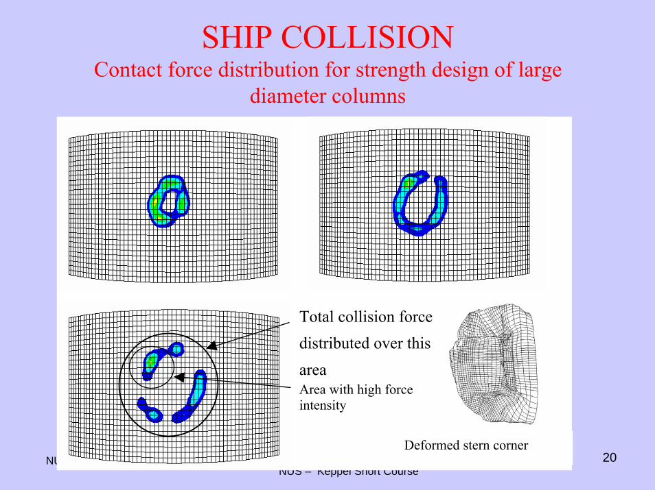
SHIP COLLISIONContact force distribution for strength design of large
diameter columns
Total collision forcedistributed over thisareaArea with high forceintensity
Deformed stern corner
NUS July 12-14, 2005 Analysis and Design for Robustness of Offshore StructuresNUS – Keppel Short Course
21
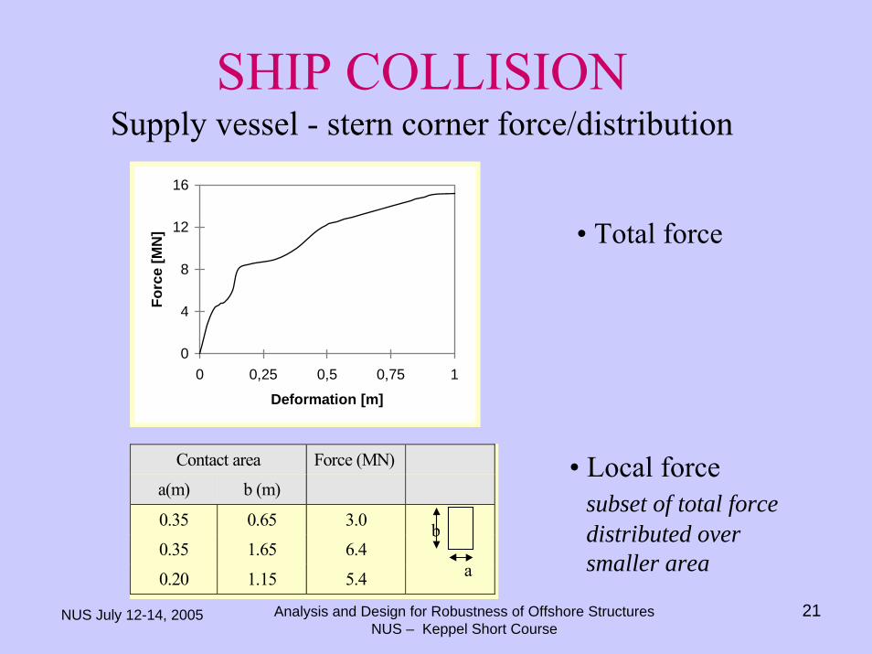
SHIP COLLISIONSupply vessel - stern corner force/distribution
0
4
8
12
16
0 0,25 0,5 0,75 1
Deformation [m]
Forc
e [M
N]
Contact area Force (MN)
a(m) b (m)
0.35 0.65 3.0
0.35 1.65 6.4
0.20 1.15 5.4 a
b
• Total force
• Local force subset of total force distributed over smaller area
NUS July 12-14, 2005 Analysis and Design for Robustness of Offshore StructuresNUS – Keppel Short Course
22
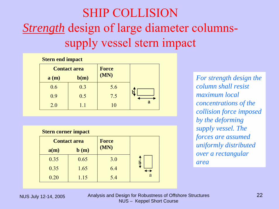
SHIP COLLISIONStrength design of large diameter columns-
supply vessel stern impact
Stern corner impact
Contact area
a(m) b (m)
Force(MN)
0.35 0.65 3.0
0.35 1.65 6.4
0.20 1.15 5.4 a
b
Stern end impact
Contact area
a (m) b(m)
Force(MN)
0.6 0.3 5.6
0.9 0.5 7.5
2.0 1.1 10
b
a
b
a
For strength design the column shall resist maximum local concentrations of the collision force imposed by the deforming supply vessel. The forces are assumed uniformly distributed over a rectangular area
NUS July 12-14, 2005 Analysis and Design for Robustness of Offshore StructuresNUS – Keppel Short Course
23
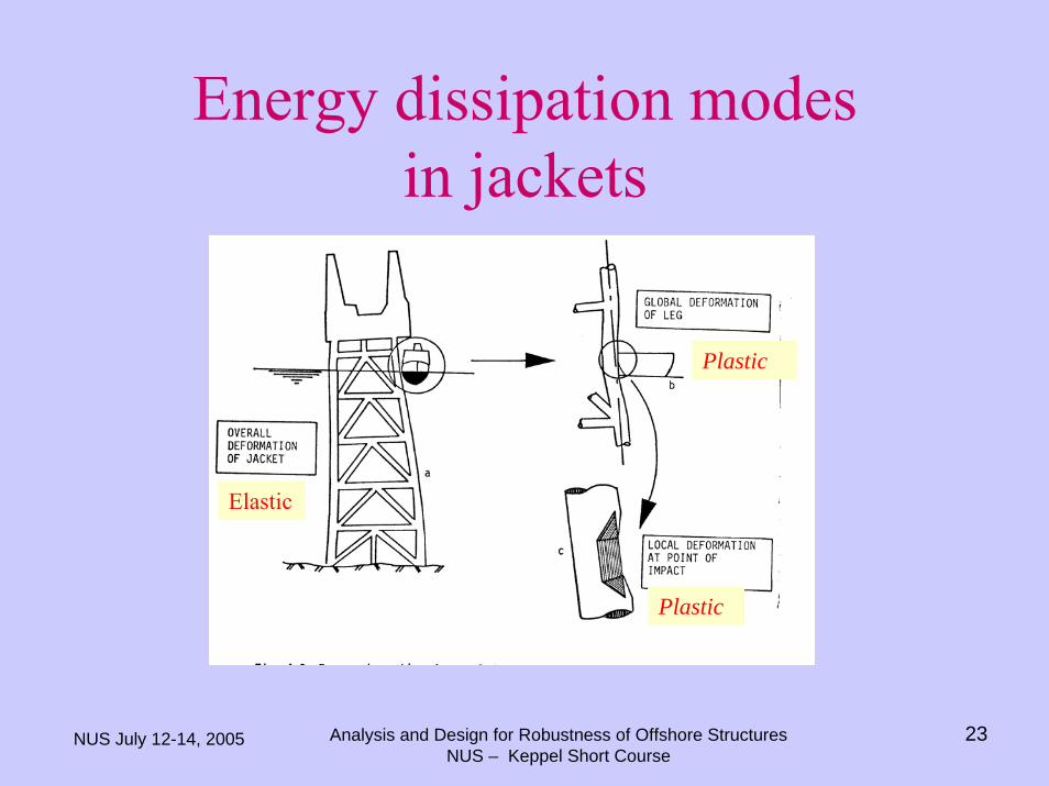
Energy dissipation modes in jackets
Elastic
Plastic
Plastic
NUS July 12-14, 2005 Analysis and Design for Robustness of Offshore StructuresNUS – Keppel Short Course
24
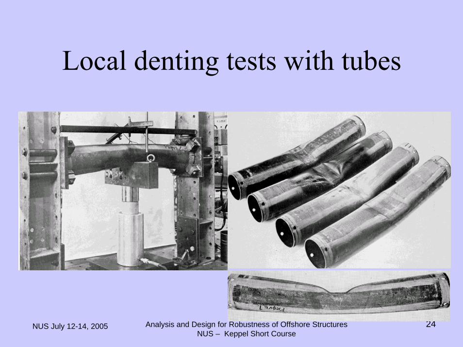
Local denting tests with tubes
NUS July 12-14, 2005 Analysis and Design for Robustness of Offshore StructuresNUS – Keppel Short Course
25
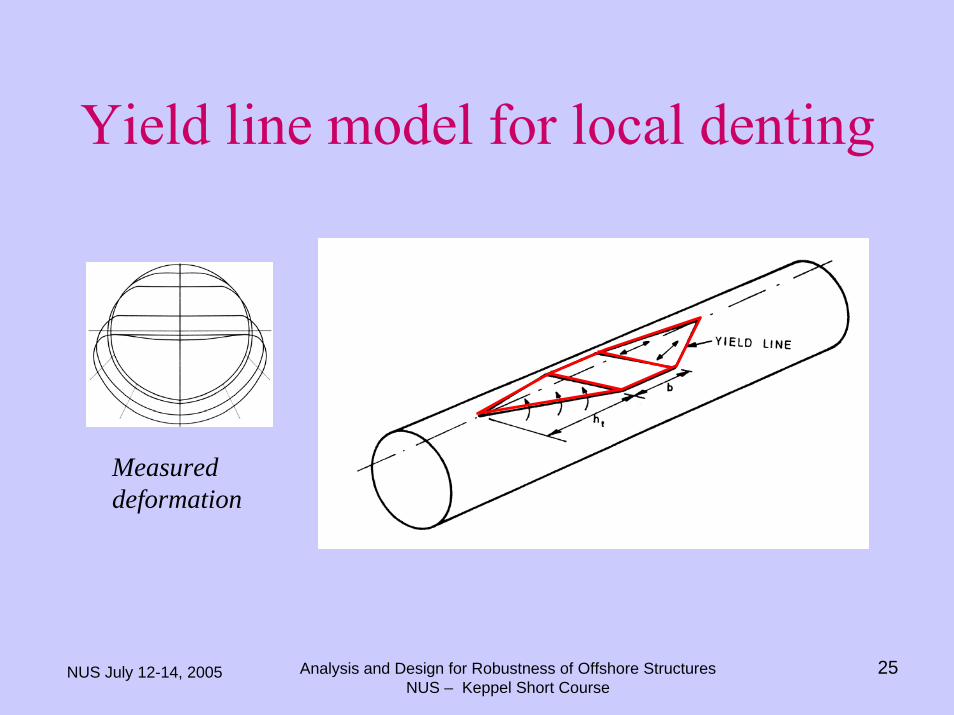
Yield line model for local denting
Measured deformation
NUS July 12-14, 2005 Analysis and Design for Robustness of Offshore StructuresNUS – Keppel Short Course
26
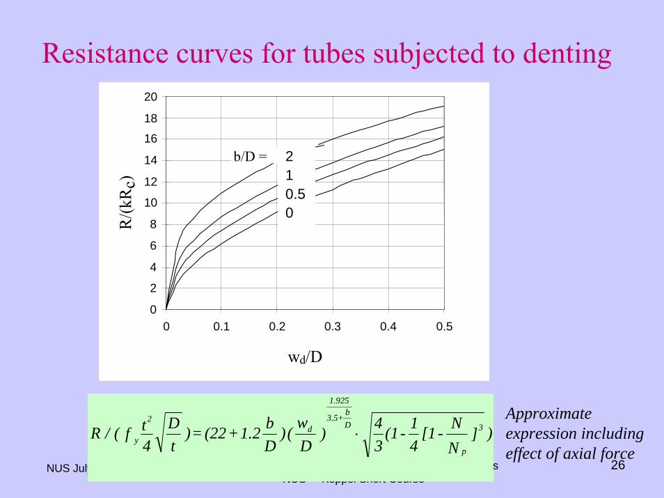
Resistance curves for tubes subjected to denting
0
2
4
6
8
10
12
14
16
18
20
0 0.1 0.2 0.3 0.4 0.5
wd/D
R/(k
Rc)
2 1 0.5 0
b/D =
)]NN-[1
41 -(1
34 )
Dw( )
Db1.2+(22 = )
tD
4tf( / R 3
p
Db+3.5
1.925
d2
y ⋅Approximate expression including effect of axial force
NUS July 12-14, 2005 Analysis and Design for Robustness of Offshore StructuresNUS – Keppel Short Course
27
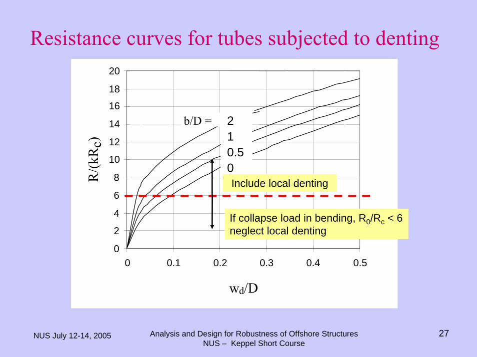
Resistance curves for tubes subjected to denting
0
2
4
6
8
10
12
14
16
18
20
0 0.1 0.2 0.3 0.4 0.5
wd/D
R/(k
Rc)
2 1 0.5 0
b/D =
If collapse load in bending, R0/Rc < 6 neglect local denting
Include local denting
NUS July 12-14, 2005 Analysis and Design for Robustness of Offshore StructuresNUS – Keppel Short Course
28
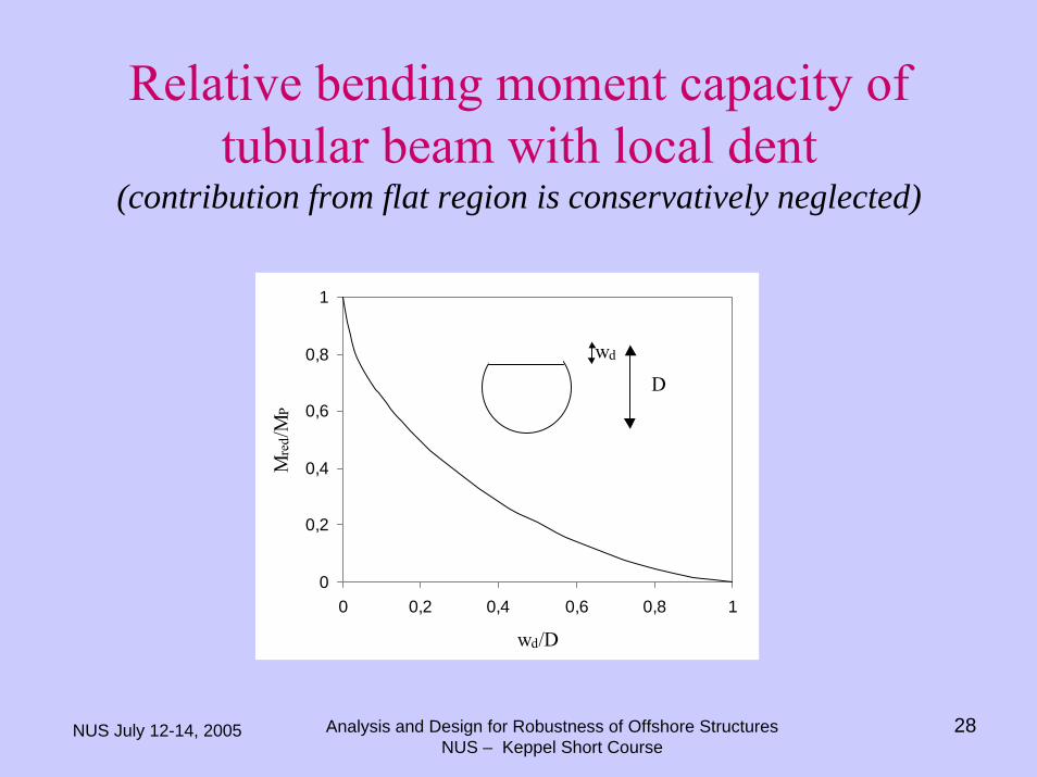
Relative bending moment capacity of tubular beam with local dent
(contribution from flat region is conservatively neglected)
0
0,2
0,4
0,6
0,8
1
0 0,2 0,4 0,6 0,8 1
wd/D
Mre
d/MP
Dwd
NUS July 12-14, 2005 Analysis and Design for Robustness of Offshore StructuresNUS – Keppel Short Course
29
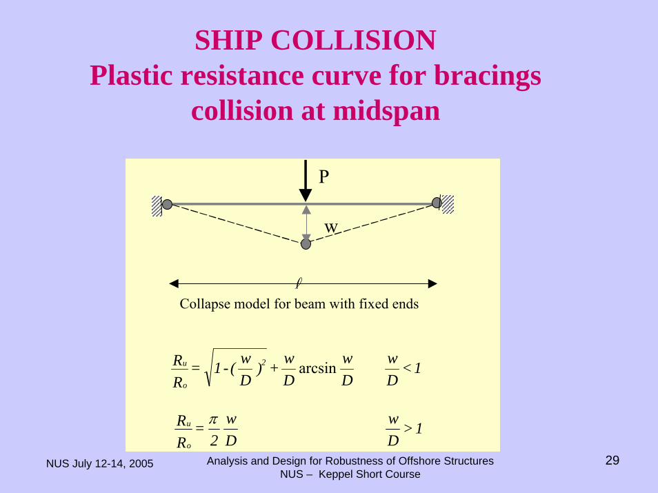
SHIP COLLISIONPlastic resistance curve for bracings
collision at midspan
w
P
Collapse model for beam with fixed ends
1 < Dw
Dw
Dw+)
Dw(-1 =
RR 2
o
u arcsin
1 > Dw
Dw
2 =
RR
o
u π
NUS July 12-14, 2005 Analysis and Design for Robustness of Offshore StructuresNUS – Keppel Short Course
30
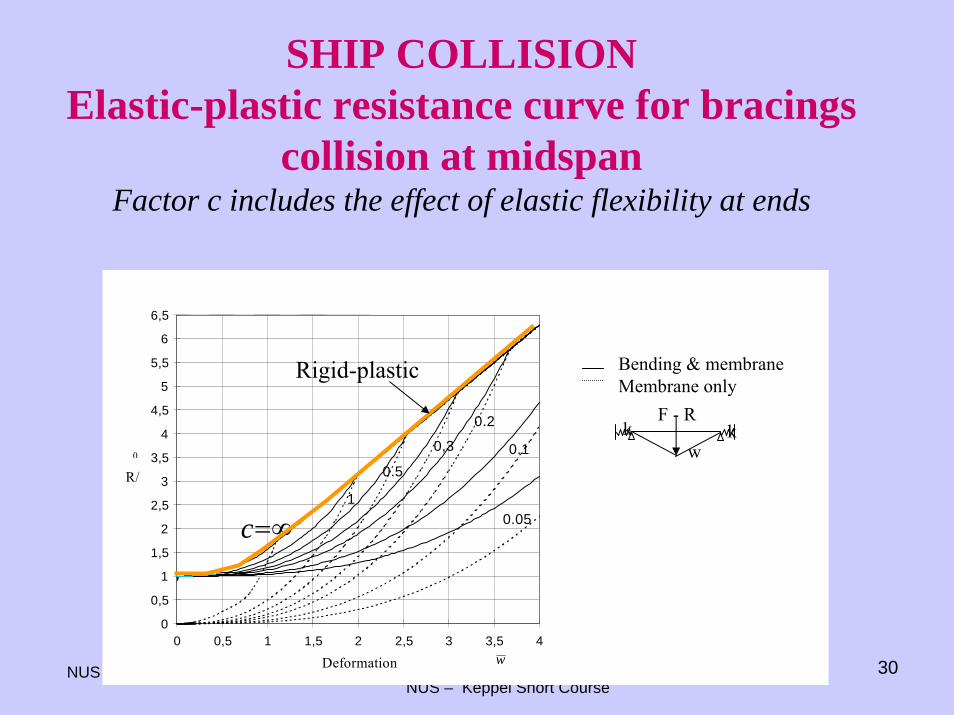
SHIP COLLISIONElastic-plastic resistance curve for bracings
collision at midspanFactor c includes the effect of elastic flexibility at ends
Bending & membraneMembrane only
k kw
F - R
0
0,5
1
1,5
2
2,5
3
3,5
4
4,5
5
5,5
6
6,5
0 0,5 1 1,5 2 2,5 3 3,5 4
Deformation
R/0
1
0.1
0.2
0,3
0.5
0.05c=∞
w
Rigid-plastic
NUS July 12-14, 2005 Analysis and Design for Robustness of Offshore StructuresNUS – Keppel Short Course
31
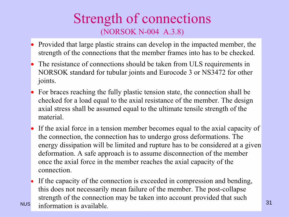
Strength of connections (NORSOK N-004 A.3.8)
• Provided that large plastic strains can develop in the impacted member, thestrength of the connections that the member frames into has to be checked.
• The resistance of connections should be taken from ULS requirements inNORSOK standard for tubular joints and Eurocode 3 or NS3472 for otherjoints.
• For braces reaching the fully plastic tension state, the connection shall bechecked for a load equal to the axial resistance of the member. The designaxial stress shall be assumed equal to the ultimate tensile strength of thematerial.
• If the axial force in a tension member becomes equal to the axial capacity ofthe connection, the connection has to undergo gross deformations. Theenergy dissipation will be limited and rupture has to be considered at a givendeformation. A safe approach is to assume disconnection of the memberonce the axial force in the member reaches the axial capacity of theconnection.
• If the capacity of the connection is exceeded in compression and bending,this does not necessarily mean failure of the member. The post-collapsestrength of the connection may be taken into account provided that suchinformation is available.
NUS July 12-14, 2005 Analysis and Design for Robustness of Offshore StructuresNUS – Keppel Short Course
32
Strength of adjacent structure
• The strength of structural members adjacent to the impactedmember/sub-structure must be checked to see whether they canprovide the support required by the assumed collapse mechanism.
• If the adjacent structure fails, the collapse mechanism must bemodified accordingly.
• Since, the physical behaviour becomes more complex withmechanisms consisting of an increasing number of members it isrecommended to consider a design which involves as few membersas possible for each collision scenario.
NUS July 12-14, 2005 Analysis and Design for Robustness of Offshore StructuresNUS – Keppel Short Course
33
Ductility limitsRef: NORSOK A.3.10.1
The maximum energy that the impacted member can dissipate will –ultimately - be limited by local buckling on the compressive side or fracture on the tensile side of cross-sections undergoing finite rotation. If the member is restrained against inward axial displacement, any local buckling must take place before the tensile strain due to membrane elongation overrides the effect of rotation induced compressive strain.If local buckling does not take place, fracture is assumed to occur when the tensile strain due to the combined effect of rotation and membrane elongation exceeds a critical value
NUS July 12-14, 2005 Analysis and Design for Robustness of Offshore StructuresNUS – Keppel Short Course
34
Tensile FractureThe degree of plastic deformation at fracture exhibits a significant scatter and depend upon the following factors:•material toughness•presence of defects•strain rate•presence of strain concentrations
Welds normally contain defects. The design should hence ensure that plastic straining takes place outside welds (overmatching weld material)
NUS July 12-14, 2005 Analysis and Design for Robustness of Offshore StructuresNUS – Keppel Short Course
35
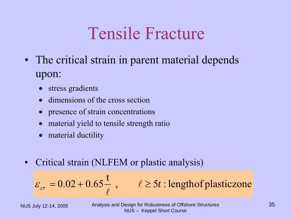
Tensile Fracture• The critical strain in parent material depends
upon:• stress gradients• dimensions of the cross section• presence of strain concentrations• material yield to tensile strength ratio• material ductility
• Critical strain (NLFEM or plastic analysis)
zoneplasticoflength:5,t65.00.02 tcr ≥+=ε
NUS July 12-14, 2005 Analysis and Design for Robustness of Offshore StructuresNUS – Keppel Short Course
36
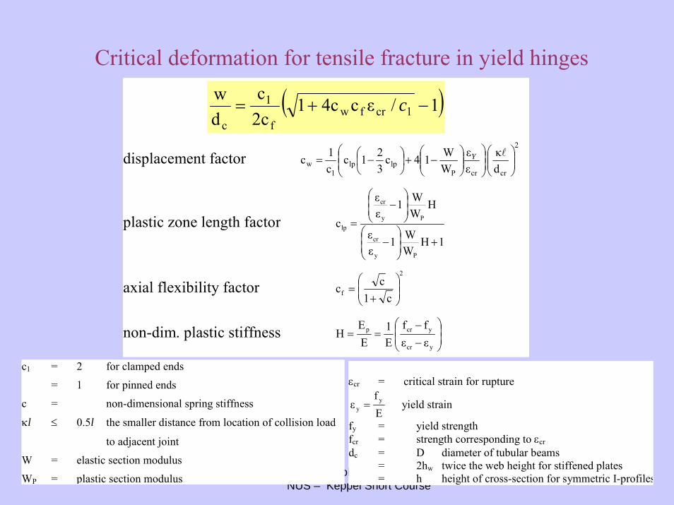
Critical deformation for tensile fracture in yield hinges
( )1/εc4c12cc
dw
1crfwf
1
c−+= c
displacement factor2
crcrPlplp
1w d
κεε
WW14c
321c
c1c ⎟⎟
⎠
⎞⎜⎜⎝
⎛⎟⎟⎠
⎞⎜⎜⎝
⎛⎟⎟⎠
⎞⎜⎜⎝
⎛−+⎟
⎠⎞
⎜⎝⎛ −= Y
plastic zone length factor 1H
WW1
εε
HWW1
εε
c
Py
cr
Py
cr
lp
+⎟⎟⎠
⎞⎜⎜⎝
⎛−
⎟⎟⎠
⎞⎜⎜⎝
⎛−
=
axial flexibility factor2
f c1cc ⎟⎟
⎠
⎞⎜⎜⎝
⎛
+=
non-dim. plastic stiffness ⎟⎟⎠
⎞⎜⎜⎝
⎛
−−
==ycr
ycrp
εεff
E1
EE
H
c1 = 2 for clamped ends
= 1 for pinned ends
c = non-dimensional spring stiffness
κl ≤ 0.5l the smaller distance from location of collision load
to adjacent joint
W = elastic section modulus
WP = plastic section modulus
εcr = critical strain for rupture
Ef
ε yy = yield strain
fy = yield strengthfcr = strength corresponding to εcrdc = D diameter of tubular beams
= 2hw twice the web height for stiffened plates= h height of cross-section for symmetric I-profiles
NUS July 12-14, 2005 Analysis and Design for Robustness of Offshore StructuresNUS – Keppel Short Course
37
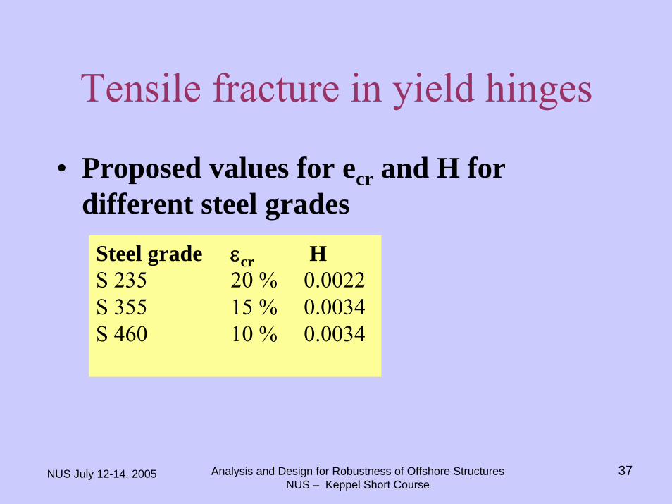
Tensile fracture in yield hinges
• Proposed values for ecr and H for different steel grades
Steel grade εcr HS 235 20 % 0.0022S 355 15 % 0.0034S 460 10 % 0.0034
NUS July 12-14, 2005 Analysis and Design for Robustness of Offshore StructuresNUS – Keppel Short Course
38
Global integrity during impact• Normally, it is unlikely that the installation will turn into a global
collapse mechanism under direct collision load, because the collisionload is typically an order of magnitude smaller than the resultant designwave force.
• Linear analysis often suffices to check that global integrity is maintained.• The installation should be checked for the maximum collision force.• For installations responding predominantly statically the maximum
collision force occurs at maximum deformation.• For structures responding predominantly impulsively the maximum
collision force occurs at small global deformation of the platform. Anupper bound to the collision force is to assume that the installation isfixed with respect to global displacement. (e.g. jack-up fixed with respectto deck displacement)