Embed Size (px)
Citation preview
Resistance
Current is somewhat like fluid flow. In fluid flow it takes a pressure difference to make the fluid flow due to the viscosity of the fluid and the size (area and length) of the pipe. So to in electricity, it takes a voltage difference to make electric current flow due to the resistance in the circuit.

Resistance
By experiment we find that if we increase the voltage, we increase the current: V is proportional to I. The constant of proportionality we call the resistance, R:
V = I*R Ohm’s LawUNITS: R = V/I so Ohm = Volt / Amp.
(We will do this experiment in lab!)

Resistance
Just as with fluid flow, the amount of resistance does not depend on the voltage (pressure) or the current (volume flow). It does, however, relate the two. The same idea applied to capacitance: the capacitance did not depend on the charge and voltage - the capacitance related the two.
As with fluid flow and with capacitance, the amount of resistance depends on the materials and shapes of the resistor.

Resistance
The resistance depends on material and geometry. For a wire, we have:
R = L / A
where is called the resistivity (in Ohm-m) and measures how hard it is for current to flow through the material, L is the length of the wire, and A is the crossectional area of the wire. One of our lab experiments will deal with Ohm’s Law and the above equation.

Electrical Power
The electrical potential energy of a charge is:
PE = q*V .
Power is the change in energy with respect to time: Power = PE / t .
Putting these two concepts together we have:
Power = (qV) / t = V(q) / t = I*V.

Electrical Power
Besides this basic equation for power:
P = I*V
remember we also have Ohm’s Law:
V = I*R .
Thus we can write the following equations for power: P = I2*R = V2/R = I*V .
To see which one gives the most insight, we need to understand what is being held constant.

Example
When using batteries, the battery keeps the voltage constant. Each D cell battery supplies 1.5 volts, so four D cell batteries in series (one after the other) will supply a constant 6 volts.
When used with four D cell batteries, a light bulb is designed to use 5 Watts of power. What is the resistance of the light bulb?

Example
We know V = 6 volts, and P = 5 Watts; we’re looking for R.
We have two equations:
P = I*V and V = I*R
which together have 4 quantities:
P, I, V & R..
We know two of these (P & V), so we should be able to solve for the other two.

Example
Using the power equation we can solve for I:
P = I*V, so 5 Watts = I * (6 volts), or
I = 5 Watts / 6 volts = 0.833 amps.
Now we can use Ohm’s Law to solve for R:
V = I*R, so
R = V/I = 6 volts / 0.833 amps = 7.2 .

Example extended
If we wanted a higher power light bulb, should we have a bigger resistance or a smaller resistance for the light bulb?
We have two relations for power that involves resistance: P = I2*R and P = V2 / R .
(The P=IV does not have R in it at all!)
Which one do we use to answer the above question?
Example extended
Answer: In this case, the voltage is being held constant due to the nature of the batteries. This means that the current will change as we change the resistance. Thus, the P = V2 / R would be the most straight-forward equation to use. This means that as R goes down, P goes up.
The answer: for more power, lower the resistance. This will allow more current to flow at the same voltage, and hence allow more power!

Connecting Resistors
Instead of making and storing all sizes of resistors, we can make and store just certain values of resistors. When we need a non-standard size resistor, we can make it by connecting two or more standard size resistors together to make an effective resistor of the value we need.

Connecting Resistors
There are two basic ways of connecting two resistors: series and parallel.
In series, we connect resistors together like railroad cars:
+ - + -
high V low V
R1 R2

Series
If we include a battery as the voltage source, the series circuit would look like this:
R1
+
Vbat
R2
Note that there is only one way around the circuit, and you have to flow through BOTH resistors in making the circuit - no choice!

Formula for Series:
To see how resistors combine to give an effective resistance when in series, we can look either at V = I*R, or at R = L/A .

Formula for SeriesWe see that in series the current must move
through both resistors. Thus Itotal = I1 = I2 .
Also, the voltage drop across the two resistors add to give the total voltage drop:
Vtotal = V1 + V2 . Thus, using V = I*R, or Reff = Vtotal / Itotal = (V1 + V2)/Itotal = V1/I1 + V2/I2
= R1 + R2 = Reffective .
Note that connecting resistors in series gives a bigger effective resistance than any of the individual resistors.

Formula for Series
Using R = L/A , we see that we have to go over both lengths, so the lengths should add. The distances are in the numerator, and so the values should add. This is just like in R = V/I where the V’s add and are in the numerator!
Parallel
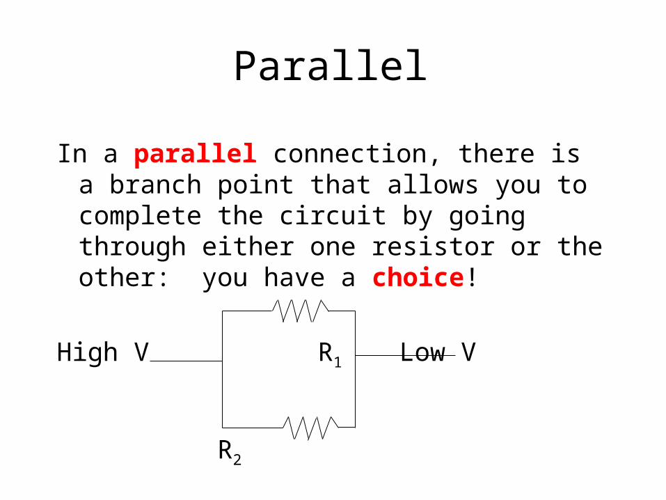
In a parallel connection, there is a branch point that allows you to complete the circuit by going through either one resistor or the other: you have a choice!
High V R1 Low V
R2

Parallel Circuit
If we include a battery, the parallel circuit would look like this:
+
Vbat R1 R2

Formula for Parallel R’s
We see that in parallel the voltage across each resistor is the same and is the same as the voltage of the battery: Vtotal = V1 = V2 .
Also, the current through the two resistors add to give the total current: Itotal = I1 + I2 .
Thus, using V = IR, or Reff = Vtotal / Itotal Reff = Vtotal / (I1 + I2), or [1/Reff] = (I1 + I2) / Vtotal = I1/V1 + I2/V2 =
1/R1 + 1/R2 = 1/Reffective .

Formula for Parallel Resistors
If we start from R = L/A , we can see that parallel resistors are equivalent to one resistor with more Area. But A is in the denominator (just like I was in the previous slide), so we need to add the inverses:
1/Reff = 1/R1 + 1/R2 . Note that connecting resistors in parallel gives a smaller
effective resistance than any of the individual resistors.

Computer Homework
The Computer Homework, Vol 3, #5 & 6, give both an introduction and problems dealing with resistors. Your homework assignment is to do #6 on Resistors Advanced.
Connecting Capacitors Together
Instead of making and storing all sizes of capacitors, we can make and store just certain values of capacitors. When we need a non-standard size capacitor, we can make it by connecting two or more standard size capacitors together to make an effective capacitor of the value we need.

Two ways
As with resistors, there are two basic ways of connecting two capacitors: series and parallel.
In series, we connect capacitors together like railroad cars; this is just like we have for resistors. Using parallel plate capacitors it would look like this:
+ - + -
high V low V
C1 C2
Series
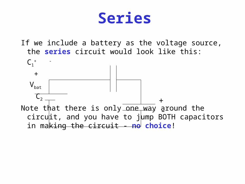
If we include a battery as the voltage source, the series circuit would look like this:
C1+ -
+
Vbat
C2
Note that there is only one way around the circuit, and you have to jump BOTH capacitors in making the circuit - no choice!
+-

Parallel
In a parallel connection, there is a branch point that allows you to complete the circuit by jumping over either one capacitor or the other: you have a choice!
High V C1 Low V
C2
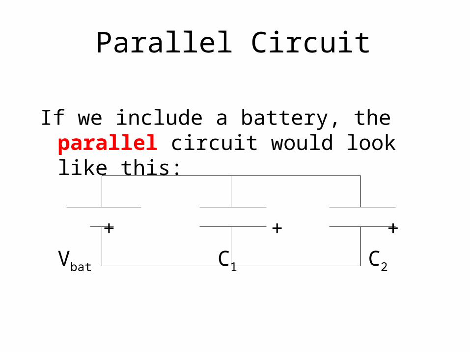
Parallel Circuit
If we include a battery, the parallel circuit would look like this:
+ + +
Vbat C1 C2

Formula for Series:
To see how capacitors combine to give an effective capacitance when in series, we can look either at C = Q/V, or at
Cparallel plate = KA / [4kd] .

Formula for SeriesUsing C = Q/V, we see that in series the charge moved from
capacitor 2’s negative plate must be moved through the battery to capacitor 1’s positive plate. Thus
Qtotal = Q1 = Q2 .
Also, the voltage drop across the two capacitors add to give the total voltage drop:
Vtotal = V1 + V2 . Thus, Ceff = Qtotal / Vtotal =
Qtotal / (V1 + V2), or [1/Ceff] = (V1 + V2) / Qtotal = V1/Q1 + V2/Q2 = 1/C1 + 1/C2 = 1/Ceffective .
Capacitors in Series
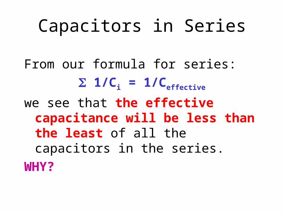
From our formula for series:
1/Ci = 1/Ceffective
we see that the effective capacitance will be less than the least of all the capacitors in the series.
WHY?

Capacitors in Series
Note that the charge moved by the voltage source (battery) is the same as the charged moved on each of the capacitors, including the least (Qtotal = Q1 = Q2 ). But the voltage across this least
capacitor is less than the voltage across the battery (since that voltage is split among all the capacitors Vtotal = V1 + V2 ). Thus for the effective
capacitance (Ceff = Qtotal / Vtotal) we have the
same charge that is moved with the largest voltage, giving us the least capacitance!

Formula for Series
Using Cparallel plate = KA / [4kd] , we see that we have to go over both distances, so the distances should add. But the distances are in the denominator, and so the inverses should add. This is just like in C = Q/V where the V’s add and are in the denominator!
Note: this is the opposite of resistors when connected in series!

Formula for Parallel Capacitors
The result for the effective capacitance for a parallel connection is different, but we can start from the same two places:
C = Q/V, or Cparallel plate = KA / [4kd] .
For parallel, both plates are across the same voltage, so Vtotal = V1 = V2 . The charge can accumulate on either plate, so:
Qtotal = Q1 + Q2 . Since the Q’s are in the numerator, we have simply: Ceff = C1 + C2.

Formula for Parallel Capacitors
If we use the parallel plate capacitor formula,
Cparallel plate = KA / [4kd] , we see that the areas add, and the areas are in the numerator, just as the Q’s were in the numerator in the C = Q/V definition.
Review of Formulas
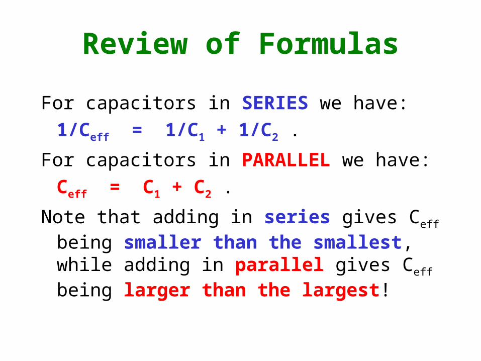
For capacitors in SERIES we have:
1/Ceff = 1/C1 + 1/C2 .
For capacitors in PARALLEL we have:
Ceff = C1 + C2 .
Note that adding in series gives Ceff being smaller than the smallest, while adding in parallel gives Ceff being larger than the largest!

Computer Homework
The Computer Homework, Vol 3, #7 & 8, give both an introduction and problems dealing with capacitors. Your homework is #8, Capacitors Advanced.

Review:
Capacitors:
Series: 1/Ceff = 1/C1 + 1/C2
Parallel: Ceff = C1 + C2
series gives smallest Ceff, parallel gives largest Ceff.
Resistors:
Series: Reff = R1 + R2
Parallel: 1/Reff = 1/R1 + 1/R2
series gives largest Reff, parallel gives smallest Reff.

The RC Circuit
What happens when we close the switch (S) in the circuit below? That is, what is I(t) ?
C
+
V R
-
S

Charging the Capacitor
Initially, the battery will “pump” charge onto the positive plate of the capacitor, removing that charge from the negative plate. (Actually, negative electrons will be removed from the positive plate and “pumped” by the battery onto the negative plate.)
The resistor will provide a resistance to the movement of this charge.

Qualitative Expectations
However, as the capacitor starts to fill up, the charges already on the capacitor will repel the new charges coming from the battery. This should slow the rate of charge being delivered (the current).
Q I
t t

Getting an equation
How do we mathematically model this process? What fundamental equation do we start from?

Conservation of Energy
From Conservation of Energy, and from PE = qV, we have the following relation:
Vi = 0 around a closed loop .
In our circuit we have three voltage sources: the battery whereVB = constant, the capacitor whereVC = (1/C)Q [from C = Q/V]), and the resistor whereVR = IR [from Ohm’s Law]).
VB - (1/C)Q - IR = 0 where I = dQ/dt .

Getting a differential equation
VB - (1/C)Q - IR = 0 where I = dQ/dt .
This gives a differential equation for Q(t), and then from I=dQ/dt, we can get I(t).
R (dQ/dt) + (1/C) Q = VB .
This is an inhomogeneous first order differential equation.

The Solution: Q(t)
The homogeneous equation:
R (dQ/dt) + (1/C)Q = 0
has the solution: QH = Qo e-t/RC .
The inhomogeneous equation:
R (dQ/dt) + (1/C)Q = VB
has the solution: QI = CVB .
Therefore we have: Q(t) = CVB + Qoe-t/RC .

Using initial conditions
Q(t) = CVB + Qoe-t/RC .
To find what Qo is, we look at initial conditions:
Q(t=0) = CVB + Qo = 0 (capacitor is initially uncharged). Therefore we have: Qo = -CVB
Q(t) = CVB (1 - e-t/RC) .
For t very big, this says: Q(t=large) = CVB, or that the capacitor will be fully charged!

The RC Circuit: charging!Q(t) = CVB (1 - e-t/RC) .
This means the current is: I(t) = dQ/dt =
-CVB(-1/RC) e-t/RC = (VB/R)e-t/RC = Io e-t/RC .
The current starts out as if the capacitor were
not there (VB=VR=IR), but decays exponentially as the capacitor becomes charged.
These two functions are plotted on the next slide, and do indeed graph like we expected earlier! The values used were:
V = 24 volts, R = 24,000 , C = 2 F .

Q(t) and I(t) for charging an RC circuit
Q(t) vs t
0.000
10.000
20.000
30.000
40.000
50.000
1 7 13 19 25 31 37 43 49 55
time in milliseconds
Q in
mic
roC
oulo
mbs
I(t) vs t
0.000
0.200
0.400
0.600
0.800
1.000
1.200
1 7 13 19 25 31 37 43 49 55
t in milliseconds
I in
mic
roa
mp
s

Discharging the Capacitor
If we allow the capacitor to become essentially fully charged, what will happen when we discharge the capacitor through a resistor?
In this case, we have the same differential equation except we no longer have the inhomogenous term, VB. Thus:
Q = Qo e-t/RC .

Solution: Discharging!
Q(t) = Qo e-t/RC . The capacitor discharges as a dying (decaying) exponential.
Note when t = RC, Q = Qo e-1 = 0.368 Qo .
Since C = Q/V, V = (1/C)Q, and since Q discharges exponentially, and C remains constant, we find VC also decreases exponentially: VC = VCoe-t/RC , and
VC(t=RC) = 0.368 VCo .
We use this fact in the lab experiment on capacitors!

Units
From the expression for a discharging capacitor: Q(t) = Qoe-t/RC , we see that the quantity RC must have units of time. Let’s check it out:
From Ohms law: V=IR, Ohm== Volt/Amp;
By definition: C = Q/V, Farad = Coul/Volt.
units of RC: *Farads = [Volt/Amp]*(Coul/Volt) = Coul/Amp = Coul/[Coul/sec] = sec.


![Fluid Flow[1]](https://img.pdfslide.us/doc/110x75/577d38c01a28ab3a6b986b59/fluid-flow1.jpg)