Embed Size (px)
Citation preview
Resilient-Seated Gate Valveswith Vertical or Cross Wall Post Indicator
Page 1 of 16 JUNE 2021 TFP1546
Worldwide Contacts www.tyco-fire.com
IMPORTANTRefer to Technical Data Sheet TFP2300 for warnings pertaining to regulatory and health information.
General DescriptionTYCO Resilient-Seated Gate Valves with Vertical and Cross Wall Indicators are used in fire protection systems for on/off operation. End connection con-figurations including Flange by Flange, Flange by Groove, and Groove by Groove are available.
The ductile iron body weighs approx-imately 50% less than conventional cast iron valves, which allows easier handling on site and reduced shipping costs.
The fully encapsulated EPDM ductile iron wedge ensures drop-tight sealing.
Valve components are either inher-ently corrosion-resistant or protected with fusion-bonded epoxy resin coating for a long, reliable service life and enhanced UV protection in exposed installations.
This valve is one of the lightest, most durable gate valves on the market today. Its design features and material selection criteria fulfill the need for a reliable, long life and easy to operate gate valve.
These valves are available with either Vertical Indicators for underground water supplies or Cross Wall Indicators for interior water systems. Both indica-tors provide external visual indication of the open or shut valve condition as well as a locking mechanism to secure a particular wedge position.
NOTICENever remove any piping component nor correct or modify any piping defi-ciencies without first de-pressurizing and draining the system. Failure to do so may result in serious personal injury, property damage, and/or impaired device performance.
It is the designer’s responsibility to select products suitable for the intended service and to ensure that pressure ratings and performance data are not exceeded. Material and gasket selection should be verified for com-patibility with the specific application. Always read and understand the instal-lation instructions.
TYCO Gate Valves described herein must be installed and maintained in compliance with this document, in addition to the standards of any other authorities having jurisdiction. Failure to do so may result in serious personal injury or impair the performance of these devices.
The owner is responsible for main-taining their mechanical system and devices in proper operating condition. The installing contractor or device man-ufacturer should be contacted with any questions.
TFP1546Page 2 of 16
NOTES• ANSI 150 and BS10 Table E
flanges feature raised faces• ANSI 125 and PN16 flanges
feature flat faces (ANSI 125 listed only for dif-ferentiation from ANSI 150, Gate Valves featuring ANSI 125 flanges are not available)
Dim. ABolt CircleDiameter
Dim. BBolt HoleDiameter
Qty. NNumber ofBolt Holes
Nominal Valve Size
Nominal Dimensions in Inches (mm)
ANSI in. DN
ANSI Class 150
ISO 7005-2 PN16
AS 2129 (Table E)
Dim. A
Dim. B
Qty. N
Dim. A
Dim. B
Qty. N
Dim. A
Dim. B
Qty. N
2 DN50
4.75 (120.7)
0.75 (19.0) 4 4.92
(125.0)0.75 (19.0) 4 4.49
(114.0)0.71 (18.0) 4
4 DN100
7.50 (190.5)
0.75 (19) 8 7.09
(180.0)0.75 (19) 8 7.00
(178.0).071 (18.0) 8
6 DN150
9.50 (241.5)
0.88 (22) 8 9.45
(240.0)0.88 (23) 8 9.25
(235.0)0.87 (22.0) 8
8 DN200
11.75 (298.5)
0.88 (22) 8 11.61
(295.0)0.88 (23) 12 111.49
(292.0)0.87 (22.0) 8
10 DN250
14.25 (362.0)
1.00 (25) 12 13.98
(355.0)1.13 (28) 12 14.02
(356.0)0.87 (22.0) 12
12 DN300
17.00 (432.0)
1.00 (25) 12 16.14
(410.0)1.13 (28) 12 15.98
(406.0)1.02
(26.0) 12
14 DN350
18.75 (476.3)
1.13 (28.6) 12 18.5
(470.0)1.102 (28) 16 18.50
(470.0)1.02
(26.0) 12
16 DN400
21.25 (539.8)
1.13 (28.6) 16 20.67
(525.0)1.22 (31) 12 20.51
(521.0)1.02
(26.0) 12
18 DN450
22.75 (577.9)
1.26 (32.0) 16 23.03
(585.0)1.22 (31) 20 19.84
(504.0)1.02
(26.0) 12
20 DN500
25.00 (635.0)
1.26 (32.0) 20 25.59
(650.0)1.34 (34) 20 25.24
(641.0)1.02
(26.0) 16
24 DN600
29.51 (749.5)
1.378 (35.0) 20 30.31
(770.0)1.46 (37) 20 29.76
(756.0)1.30
(33.0) 16
3
19
10
13
4
8
11
16
18
15
1
14
9
12
7
2
20
21
17
5
6
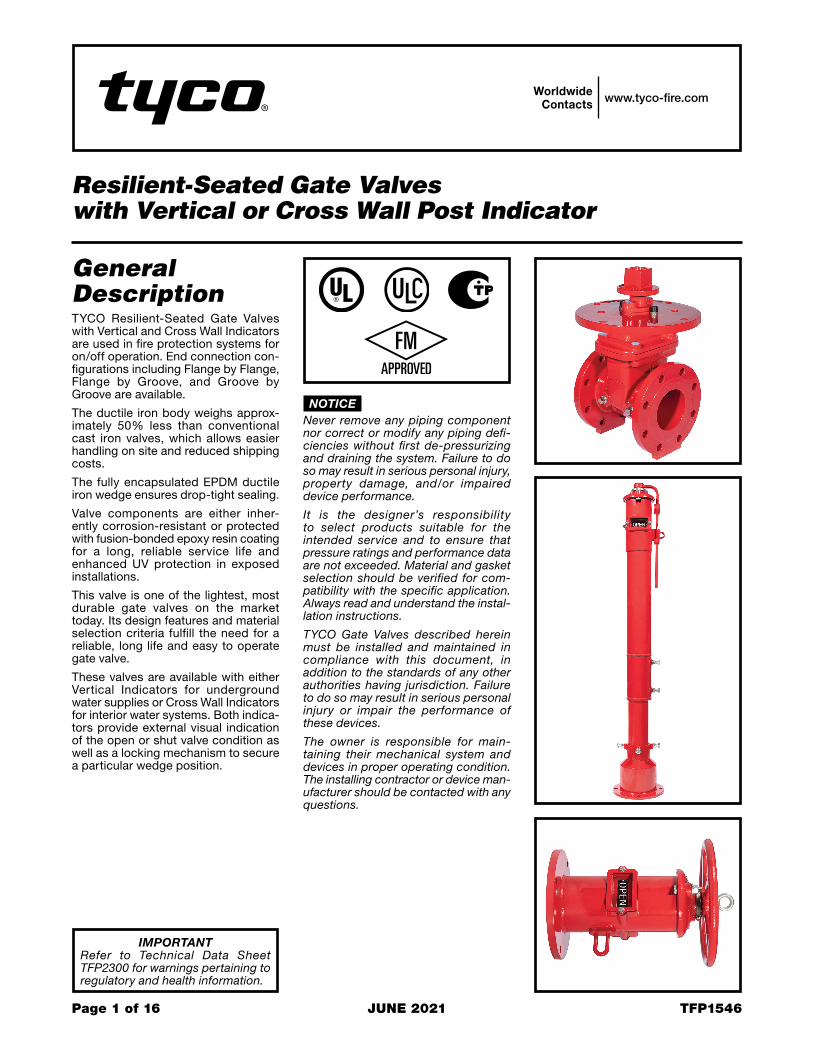
No. Description Qty. Material1 Body. . . . . . . . 1 ASTM A536
65-45-122 Wedge . . . . . . 1 EPDM3 Stem. . . . . . . . 1 AISI SS2404 Bonnet . . . . . . 1 ASTM A536
65-45-125 Half-Ring . . . . 1 ASTM C11006 Seal Seat . . . . 1 ASTM A536
65-45-127 Disc Nut . . . . . 1 ASTM B62
C836008 Seal Ring . . . . 1 EPDM9 O-Ring . . . . . . 2 EPDM
10 Dust Cap . . . . 1 EPDM11 Hex Socket
Cap Screw . . . 2 8.8 Rating12 Wench
Nut . . . . . . . . . 1ASTM A53665-45-12
13 Washer . . . . . . 1 ASTM SS30414 Hex Socket
Cap Screw . . . 1 8.8 Rating15 Plug . . . . . . . . 2 ASTM SS30416 Gasket . . . . . . 1 EPDM17 Hex Socket
Cap Screw . . . 4-10 ASTM SS30418 Post
Flange . . . . . . 1ASTM A53665-45-12
19 Washer . . . . . . 2 Carbon SteelGalvanized
20 SpringWasher . . . . . . 2
Carbon SteelGalvanized
21 Hex SocketCap Screw . . . 2 8.8 Rating
FIGURE 1 POST INDICATOR GATE VALVE
ASSEMBLY
TABLE A GATE VALVE SELECTION FLANGE DRILLING SPECIFICATIONS
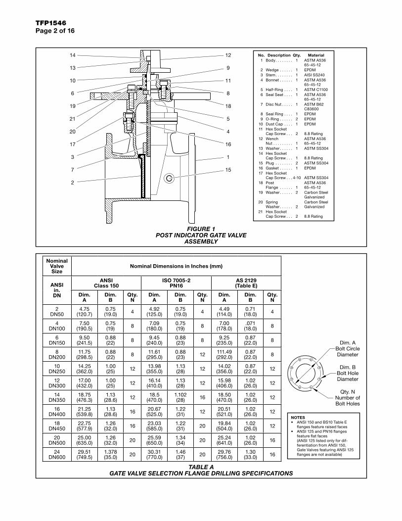
TFP1546Page 3 of 16
FLANGE x FLANGE
L
FLANGE x GROOVE
L
GROOVE x GROOVE
L
CL
P
Nominal Valve Size
Nominal Pipe Size
Nominal Dimen-sions
in. (mm)P
Tapping Boss Size ANSI in.
NPT
Approx. Weight
F x F lb
(kg)
Approx. Weight F x G
lb (kg)
Approx. Weight G x G
lb (kg)
ANSI in. DN
O.D. in.
(mm)L CL
2 DN50
2.375 (60.3)
7.00 (178)
10.98 (279)
1/2
25.0 (11.34)
24.1 (10.92)
23.11 (10.49)
4 DN100
4.500 (114.3)
9.00 (229)
13.07 (332)
77.0 (35)
73.5 (33.4)
50.8 (23.1)
– DN150
6.500 (165.1)
10.50 (267)
17.17 (436)
110.0 (50)
105.7 (48)
101.4 (46.1)
6 DN150
6.625 (168.3)
10.50 (267)
17.17 (436)
110.0 (50)
105.7 (48)
101.4 (46.1)
8 DN200
8.625 (219.1)
11.50 (292)
20.47 (520) 3/4 182.6
(83)184.8 (84)
187 (85)
10 DN250
10.750 (273.1)
13.00 (330)
24.41 (620)
1
271.7 (123.5)
266.2 (121)
260.7 (118.5)
12 DN300
12.750 (323.9)
14.00 (356)
26.38 (670)
386.1 (175.5)
378.4 (172)
370.7 (168.5)
14 DN350
14.000 (355.6)
15.00 (381.0)
33.94 (862)
506.0 (230) — —
16 DN400
16.000 (406.4)
15.98 (406.0)
36.93 (938)
712.8 (324) — —
18 DN450
18.000 (457.2)
17.00 (432.0)
41.61 (1057)
968 (440) — —
20 DN500
20.000 (508.0)
17.99 (457.0)
44.96 (1142)
1403.6 (638) — —
24 DN600
24.000 (609.6)
20.0 (508.0)
50.98 (1295)
1804 (820) — —
FIGURE 2 POST INDICATOR GATE VALVE
NOMINAL DIMENSIONS
TFP1546Page 4 of 16
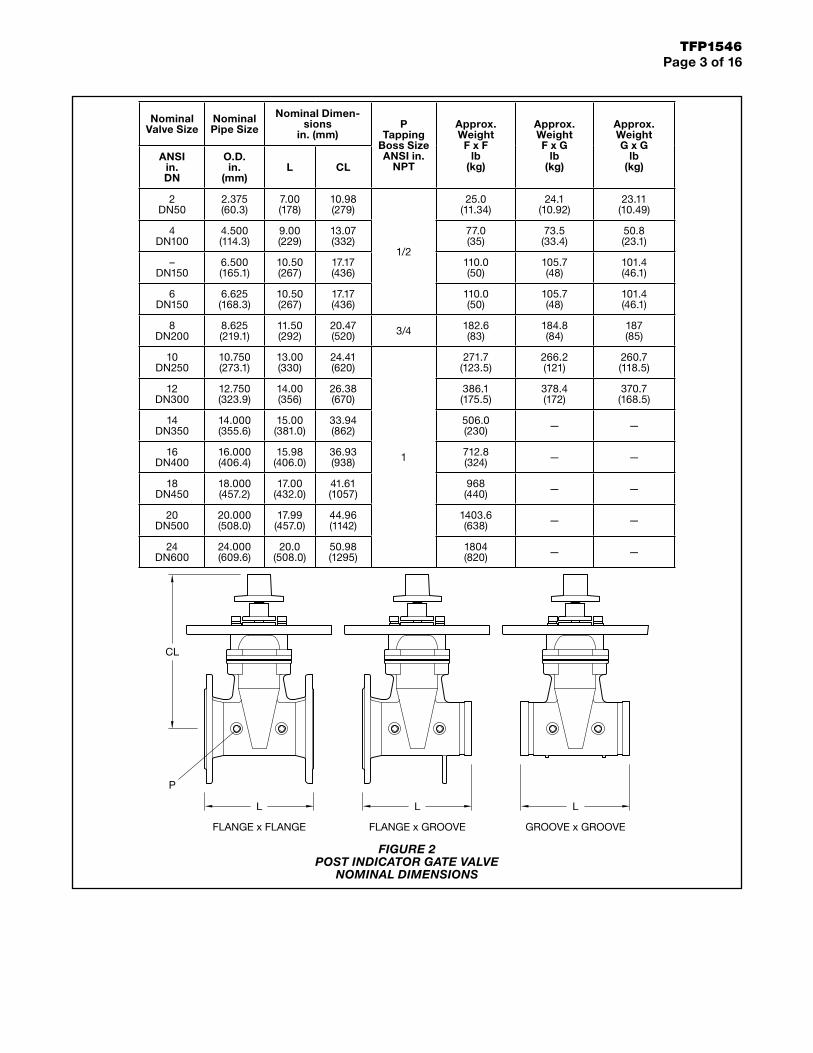
BURY LINE
19
20
21
22
16
23
13
24
2
26
1
25
15
14
5
4
7
10
9
8
12
3
6
11
17
18
No. Description Qty. Material1 Locking
Wrench. . . . . . 1 ASTM A126B2 Operating
Nut . . . . . . . . . 1 SUS3043 Hex Cap
Screw . . . . . . . 2 ASTM A1054 Hex Nut . . . . . 2 ASTM A1055 Snap Ring . . . 1 AISI 0666 Target Carrier
Yoke . . . . . . . . 1 SUS3047 Target . . . . . . . 4 ASTM B1088 Hex Cap
Screw . . . . . . . 4 ASTM A1059 Window
Glass . . . . . . . 2 Lexan-UN10 Window
GlassGasket . . . . . . 2 PTFE
11 Hex CapScrew . . . . . . . 4 ASTM A105
12 Hex Nut . . . . . 4 ASTM A10513 Upper
Post . . . . . . . . 1 ASTM A53614 Hex Cap
Screw . . . . . . . 6 ASTM A10515 Hex Nut . . . . . 6 ASTM A10516 Mounting
Flange . . . . . . 1 ASTM A126B17 Hex Cap
Screw . . . . . . . 4 ASTM A10518 Hex Nut . . . . . 4 ASTM A10519 Connection
TubeCoupling. . . . . 1 ASTM A536
20 Cotter Pin. . . . 1 AISI 30421 Inner
Pipe . . . . . . . . 1 ASTM A5322 Connection
Tube . . . . . . . . 1 AISI 104523 Plug . . . . . . . . 1 AISI 30424 Cap. . . . . . . . . 1 ASTM A126B25 Phillips
HeadScrew . . . . . . . 1 AISI 304
26 Lock Hasp . . . 1 ASTM 307B
FIGURE 3 VERTICAL INDICATOR POST
ASSEMBLY
TFP1546Page 5 of 16
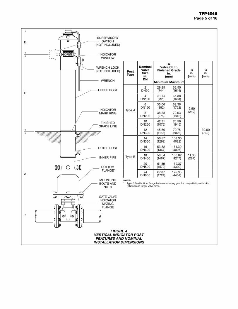
FINISHEDGRADE LINE
INDICATORMARK RING
BOTTOMFLANGE*
MOUNTINGBOLTS AND
NUTS
SUPERVISORYSWITCH
(NOT INCLUDED)
WRENCH LOCK(NOT INCLUDED)
INDICATORWINDOW
UPPER POST
WRENCH
OUTER POST
INNER PIPE
GATE VALVEINDICATOR
MATINGFLANGE
A
C
B
Post Type
Nominal Valve Size in. DN
A Valve CL to
Finished Grade in.
(mm)
B in.
(mm)
C in.
(mm)
Minimum Maximum
Type A
2 DN50
29.25 (744)
63.50 (1614)
9.50 (240)
30.00 (760)
4 DN100
31.13 (791)
65.38 (1661)
6 DN150
35.06 (892)
69.38 (1762)
8 DN200
38.38 (975)
72.63 (1845)
10 DN250
42.31 (1075)
76.56 (1945)
12 DN300
45.50 (1156)
79.75 (2026)
Type B
14 DN350
50.87 (1292)
158.35 (4022)
11.30 (287)
16 DN400
53.82 (1367)
161.30 (4097)
18 DN450
58.54 (1487)
166.02 (4217)
20 DN500
61.89 (1572)
169.37 (4302)
24 DN600
67.87 (1724)
175.35 (4454)
NOTE:* Type B Post bottom flange features reducing gear for compatibility with 14 in.
(DN350) and larger valve sizes.
FIGURE 4 VERTICAL INDICATOR POST FEATURES AND NOMINAL
INSTALLATION DIMENSIONS

TFP1546Page 6 of 16
Installation
Step 1. Rotate gate valve top cap clockwise to fully open gate valve.
Step 2. Remove indicator wrench and cap bolts and nuts.
Step 3. Remove cap assembly from body cavity.
Step 4. Rotate target carrier assembly around operating nut stem to adjust distance between top surface of carrier yoke and bottom flange of cap to 5 in. (127 mm).
Step 5. Engage middle tooth (center-line) of OPEN target in fourth notch in serrated edge from top surface of carrier yoke. Locate SHUT target per Dimension T in table.
Step 6. Temporarily engage connec-tion tube coupling onto gate valve top cap and attach indicator to gate valve mounting flange with bolts and nuts.
Step 7. Loosen jam nuts and bolts to free indicator outer pipe from inner pipe. Adjust outer pipe bury line even with finished grade.
Step 8. Tighten bolts and jam nuts to secure outer pipe onto inner pipe.
Step 9. Mark cut line on connection tube 1 1/2 in. (40 mm) above top flange of body.
Vertical Indicator Post, 4 in. to 12 in. (DN100 to DN300) Valves
Step 1 Step 2 Step 3
5 IN.(127 mm)
Step 4
VALVESIZE
IN. (DN)
DIM. TIN. (mm)
T
4thNOTCH
8 (DN200)
10 (DN250)
12 (DN300)
6 (DN150)
4 (DN100)
2.36 (60)
2.95 (75)
3.74 (95)
1.77 (45)
1.18 (30)
Step 5 Step 6
Step 7 Step 81-1/2"
(40 mm)
CUTLINE
Step 9
TFP1546Page 7 of 16
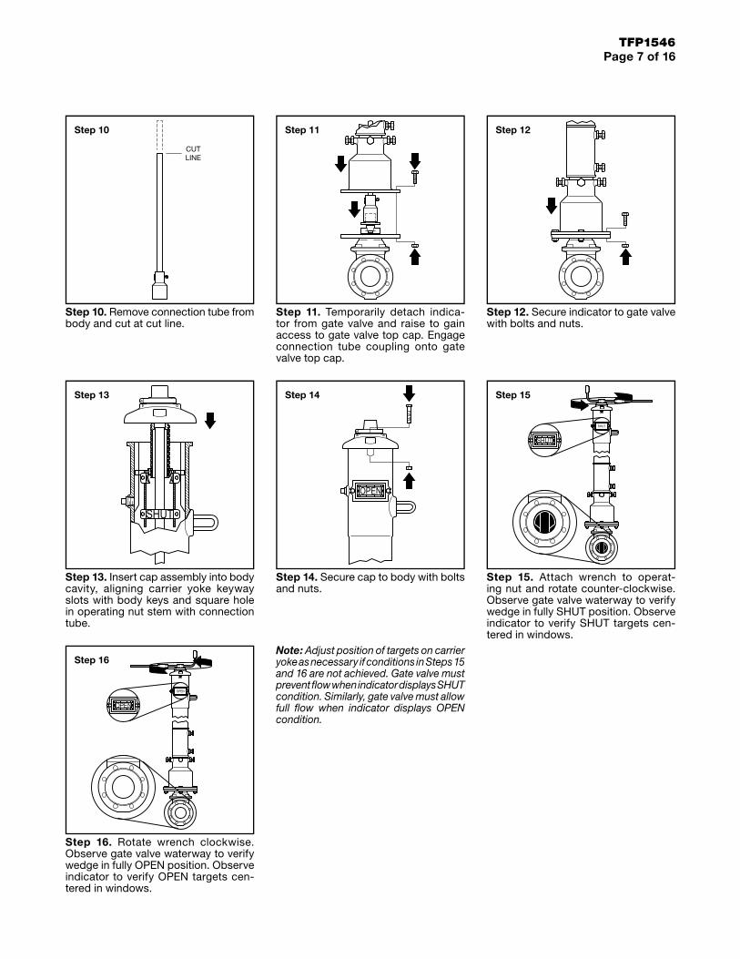
Step 10. Remove connection tube from body and cut at cut line.
Step 11. Temporarily detach indica-tor from gate valve and raise to gain access to gate valve top cap. Engage connection tube coupling onto gate valve top cap.
Step 12. Secure indicator to gate valve with bolts and nuts.
Step 13. Insert cap assembly into body cavity, aligning carrier yoke keyway slots with body keys and square hole in operating nut stem with connection tube.
Step 14. Secure cap to body with bolts and nuts.
Step 15. Attach wrench to operat-ing nut and rotate counter-clockwise. Observe gate valve waterway to verify wedge in fully SHUT position. Observe indicator to verify SHUT targets cen-tered in windows.
Step 16. Rotate wrench clockwise. Observe gate valve waterway to verify wedge in fully OPEN position. Observe indicator to verify OPEN targets cen-tered in windows.
Note: Adjust position of targets on carrier yoke as necessary if conditions in Steps 15 and 16 are not achieved. Gate valve must prevent flow when indicator displays SHUT condition. Similarly, gate valve must allow full flow when indicator displays OPEN condition.
CUTLINE
Step 10 Step 11 Step 12
Step 13 Step 14 Step 15
Step 16
TFP1546Page 8 of 16
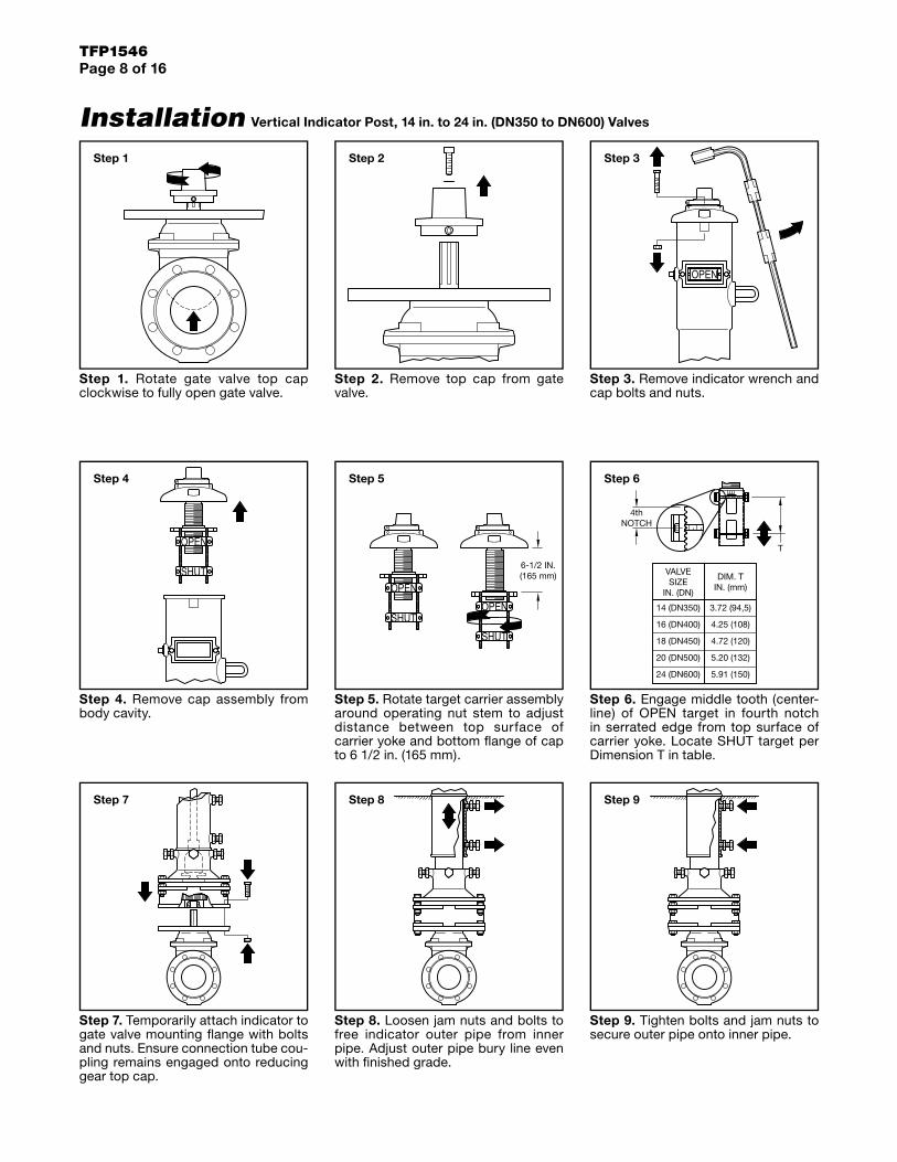
Installation
Step 1. Rotate gate valve top cap clockwise to fully open gate valve.
Step 2. Remove top cap from gate valve.
Step 3. Remove indicator wrench and cap bolts and nuts.
Step 4. Remove cap assembly from body cavity.
Step 5. Rotate target carrier assembly around operating nut stem to adjust distance between top surface of carrier yoke and bottom flange of cap to 6 1/2 in. (165 mm).
Step 6. Engage middle tooth (center-line) of OPEN target in fourth notch in serrated edge from top surface of carrier yoke. Locate SHUT target per Dimension T in table.
Step 7. Temporarily attach indicator to gate valve mounting flange with bolts and nuts. Ensure connection tube cou-pling remains engaged onto reducing gear top cap.
Step 8. Loosen jam nuts and bolts to free indicator outer pipe from inner pipe. Adjust outer pipe bury line even with finished grade.
Step 9. Tighten bolts and jam nuts to secure outer pipe onto inner pipe.
Vertical Indicator Post, 14 in. to 24 in. (DN350 to DN600) Valves
Step 1 Step 2 Step 3
Step 4
6-1/2 IN.(165 mm)
Step 5
18 (DN450) 4.72 (120)
20 (DN500)
24 (DN600)
5.20 (132)
5.91 (150)
16 (DN400) 4.25 (108)
14 (DN350) 3.72 (94,5)
VALVESIZE
IN. (DN)
DIM. TIN. (mm)
T
4thNOTCH
Step 6
Step 7 Step 8 Step 9
TFP1546Page 9 of 16
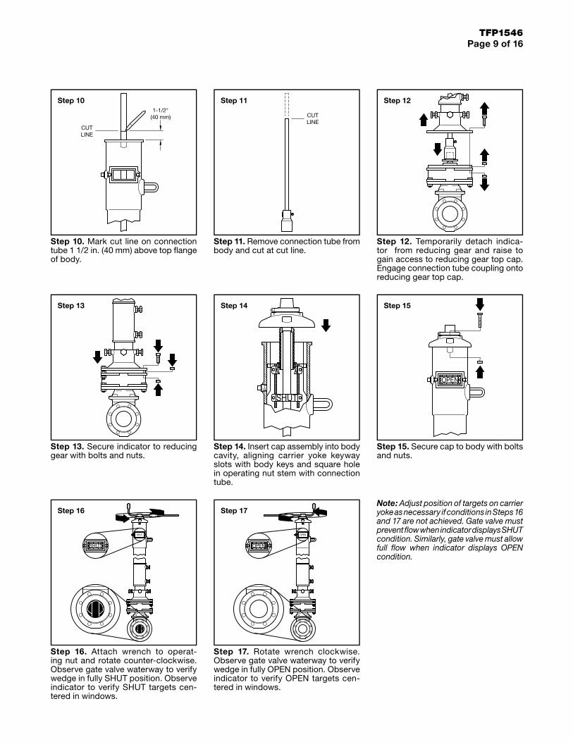
Step 10. Mark cut line on connection tube 1 1/2 in. (40 mm) above top flange of body.
Step 11. Remove connection tube from body and cut at cut line.
Step 12. Temporarily detach indica-tor from reducing gear and raise to gain access to reducing gear top cap. Engage connection tube coupling onto reducing gear top cap.
Step 13. Secure indicator to reducing gear with bolts and nuts.
Step 14. Insert cap assembly into body cavity, aligning carrier yoke keyway slots with body keys and square hole in operating nut stem with connection tube.
Step 15. Secure cap to body with bolts and nuts.
Step 16. Attach wrench to operat-ing nut and rotate counter-clockwise. Observe gate valve waterway to verify wedge in fully SHUT position. Observe indicator to verify SHUT targets cen-tered in windows.
Step 17. Rotate wrench clockwise. Observe gate valve waterway to verify wedge in fully OPEN position. Observe indicator to verify OPEN targets cen-tered in windows.
Note: Adjust position of targets on carrier yoke as necessary if conditions in Steps 16 and 17 are not achieved. Gate valve must prevent flow when indicator displays SHUT condition. Similarly, gate valve must allow full flow when indicator displays OPEN condition.
1-1/2"(40 mm)
CUTLINE
Step 10
CUTLINE
Step 11 Step 12
Step 13 Step 14 Step 15
Step 16 Step 17
TFP1546Page 10 of 16
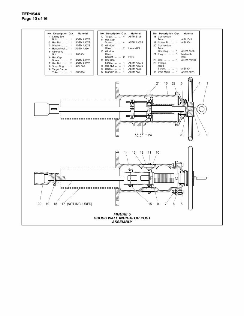
(NOT INCLUDED)
451621 122
32324 2
12 11 101314
615 9 818 171920 7
No. Description Qty. Material1 Lifting Eye
Bolt. . . . . . . . . 1 ASTM A307B2 Hex Nut . . . . . 1 ASTM A307B3 Washer . . . . . . 1 ASTM A307B4 Handwheel. . . 1 ASTM A5365 Operating
Nut . . . . . . . . . 1 SUS3046 Hex Cap
Screw . . . . . . . 2 ASTM A307B7 Hex Nut . . . . . 2 ASTM A307B8 Snap Ring . . . 1 AISI 0669 Target Carrier
Yoke . . . . . . . . 1 SUS304
No. Description Qty. Material10 Target . . . . . . . 4 ASTM B10811 Hex Cap
Screw . . . . . . . 4 ASTM A307B12 Window
Glass . . . . . . . 2 Lexan-UN13 Window
GlassGasket . . . . . . 2 PTFE
14 Hex CapScrew . . . . . . . 4 ASTM A307B
15 Hex Nut . . . . . 4 ASTM A307B16 Body. . . . . . . . 1 ASTM A53617 Stand Pipe . . . 1 ASTM A53
No. Description Qty. Material18 Connection
Tube . . . . . . . . 1 AISI 104519 Cotter Pin. . . . 1 AISI 30420 Connection
TubeCoupling. . . . . 1 ASTM A536
21 Plug . . . . . . . . 1 MalleableIron
22 Cap. . . . . . . . . 1 ASTM A126B23 Phillips
HeadScrew . . . . . . . 1 AISI 304
24 Lock Hasp . . . 1 ASTM 307B
FIGURE 5 CROSS WALL INDICATOR POST
ASSEMBLY
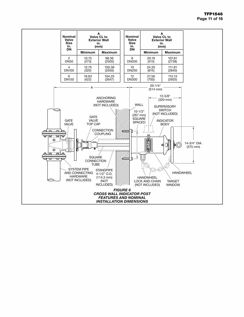
TFP1546Page 11 of 16
HANDWHEELLOCK AND CHAIN(NOT INCLUDED)
TARGETWINDOW
ANCHORINGHARDWARE
(NOT INCLUDED)
12-5/8"(320 mm)
SUPERVISORYSWITCH
(NOT INCLUDED)
INDICATORBODY
CONNECTIONCOUPLING
GATEVALVE
TOP CAPGATEVALVE
STANDPIPE4-1/2" O.D.(114,3 mm)
(NOTINCLUDED)
SYSTEM PIPEAND CONNECTING
HARDWARE(NOT INCLUDED)
10-1/2"(267 mm)SQUARESPACED
A
HANDWHEEL
WALL
14-3/4" DIA.(375 mm)
20-1/4"(514 mm)
SQUARECONNECTION
TUBE
Nominal Valve Size in. DN
A Valve CL to
Exterior Wall in.
(mm)
Minimum Maximum
2 DN50
10.75(273)
98.36(2500)
4 DN100
12.75(325)
100.36(2550)
6 DN150
16.63(422)
104.25(2647)
Nominal Valve Size in. DN
A Valve CL to
Exterior Wall in.
(mm)
Minimum Maximum
8 DN200
20.19(513)
107.81(2738)
10 DN250
24.25(615)
111.81(2840)
12 DN300
27.56(700)
115.13(2925)
FIGURE 6 CROSS WALL INDICATOR POST
FEATURES AND NOMINAL INSTALLATION DIMENSIONS
TFP1546Page 12 of 16
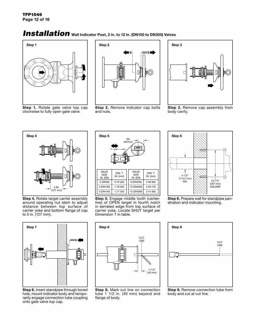
Installation
Step 1. Rotate gate valve top cap clockwise to fully open gate valve.
Step 2. Remove indicator cap bolts and nuts.
Step 3. Remove cap assembly from body cavity.
Step 4. Rotate target carrier assembly around operating nut stem to adjust distance between top surface of carrier yoke and bottom flange of cap to 5 in. (127 mm).
Step 5. Engage middle tooth (center-line) of OPEN target in fourth notch in serrated edge from top surface of carrier yoke. Locate SHUT target per Dimension T in table.
Step 6. Prepare wall for standpipe pen-etration and indicator mounting.
Step 6. Insert standpipe through bored hole, mount indicator body and tempo-rarily engage connection tube coupling onto gate valve top cap.
Step 8. Mark cut line on connection tube 1 1/2 in. (40 mm) beyond end flange of body.
Wall Indicator Post, 2 in. to 12 in. (DN100 to DN300) Valves
Step 9. Remove connection tube from body and cut at cut line.
Step 1 Step 2 Step 3
5 IN.(127 mm)
Step 44th
NOTCH
T
VALVESIZE
IN. (DN)
DIM. TIN. (mm)
VALVESIZE
IN. (DN)
DIM. TIN. (mm)
6 (DN150)
4 (DN100)
1.77 (45)
1.18 (30)
2 (DN50) 0.79 (20) 8 (DN200)
10 (DN250)
12 (DN300)
2.36 (60)
2.95 (75)
3.74 (95)
Step 5
10-1/2"(267 mm)SQUARE
4-1/2"(114,3 mm)
DIA.
Step 6
Step 7
1-1/2"(40 mm)
CUTLINE
Step 8
CUTLINE
Step 9
TFP1546Page 13 of 16
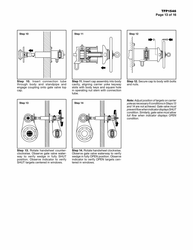
Step 10. Insert connection tube through body and standpipe and engage coupling onto gate valve top cap.
Step 11. Insert cap assembly into body cavity, aligning carrier yoke keyway slots with body keys and square hole in operating nut stem with connection tube.
Step 12. Secure cap to body with bolts and nuts.
Step 13. Rotate handwheel counter-clockwise. Observe gate valve water-way to verify wedge in fully SHUT position. Observe indicator to verify SHUT targets centered in windows.
Step 14. Rotate handwheel clockwise. Observe gate valve waterway to verify wedge in fully OPEN position. Observe indicator to verify OPEN targets cen-tered in windows.
Note: Adjust position of targets on carrier yoke as necessary if conditions in Steps 13 and 14 are not achieved. Gate valve must prevent flow when indicator displays SHUT condition. Similarly, gate valve must allow full flow when indicator displays OPEN condition.
Step 10 Step 11 Step 12
Step 13 Step 14
TFP1546Page 14 of 16
Care and MaintenanceThe TYCO Resilient-Seated Gate Valves with Vertical or Cross Wall Post Indicators must be maintained and ser-viced in accordance with this section.
Before closing a fire protection system main control valve for maintenance work on the fire protection system that it controls, permission to shut down the affected fire protection system must be obtained for the proper authorities and notify all personnel who may be affected by this action.
After placing a fire protection system in service, notify the proper authorities and advise those responsible for moni-toring proprietary and/or central station alarms.
The owner is responsible for the inspection, testing, and maintenance of their fire protection system and devices in compliance with this document, as well as with the applicable standards of the NFPA, for example, NFPA 25, in addition to the standards of any author-ities having jurisdiction. Contact the installing contractor or sprinkler man-ufacturer regarding any questions.
Automatic sprinkler systems are rec-ommended to be inspected, tested, and maintained by a qualified inspec-tion service in accordance with local requirements and/or national codes.
Gate ValveDebris lodged in the sealing area of the wedge may cause the valve to close hard. Backing off the indicator wrench or handwheel and closing it again, several times if necessary, can correct this problem.
The valve should never be forced to seat by applying a wrench or exten-sion to the lever, as it may distort the valve components or score the sealing surfaces. All replacement parts must be obtained from the manufacturer to assure proper operation of the valve.
Vertical Indicator PostIt is recommended that Vertical Indi-cator Posts used to operate fire pro-tection system water control valves be locked in the fully open position using the wrench. The locks must be sturdy and resistant to breakage except by heavy bolt cutters.
It is recommended that a visual inspec-tion be carried out on a monthly basis to ensure:
• the Post Cap, Upper Barrel, and win-dows have not been damaged
• the Targets indicate that the valve is open
• the Wrench is in place on the Post and is securely locked
It is further recommended that on a quarterly basis, the Vertical Indicator Post should be closed two turns and then reopened to verify that the PIV is in the fully open position and prop-erly engages with the Post. Where a Supervisory Switch is installed, a check should be undertaken to ensure that the contacts are working properly.
Any missing or damaged parts should be immediately replaced.
Note: If the target carrier yoke must be disassembled or cleaned for any reason, apply LOCTITE LB8150 or an equivalent grease as a lubricant to the stainless-steel threads of the operating nut prior to reassembly.
Technical DataSizes2 in. to 24 in. (DN50 to DN600)
ApprovalsUL and ULC Listed FM Approved Russian Fire Certificate
UL, ULC and FM Maximum Working Pressure• 2 in. to 12 in. (DN200 to DN300):
300 psi (20,7 bar)
• 14 in. to 24 in. (DN350 to DN600): 250 psi (17,2 bar)
FlangesASME B16.1/ASME B16.42 EN 1092-2/ISO 7005-2/ Drilled to ANSI Class 150, PN16, or AS 2129. See Table E.
Materials of ConstructionSee individual valve and indicator parts lists in Figures 1, 4, and 6.
2 IN
CH
(DN
50)
8 IN
CH
(DN
200)
4 IN
CH
(DN
100)
6 IN
CH
(DN
150)
10 IN
CH
(DN
250)
12 IN
CH
(DN
300)
FLOW RATE IN GALLONS PER MINUTE (GPM)
FLOW RATE IN LITRES PER MINUTE (LPM)(1 GPM = 3,785 LPM)
400300200100 600 800 1000 60002000 3000 4000 10000
0.10
0.20
0.30
0,0080,009
0,005
0,006
0,007
0,010
0,004
0,020
4000 60002000 3000800400 600 1000 20000 3000010000
0.06
0.05
0.090.080.07
NO
MIN
AL
PR
ES
SU
RE
DR
OP
IN B
AR
(1 P
SI =
0,0
6895
BA
R)
NO
MIN
AL
PR
ES
SU
RE
DR
OP
IN P
OU
ND
S P
ER
SQ
UA
RE
INC
H (P
SI)
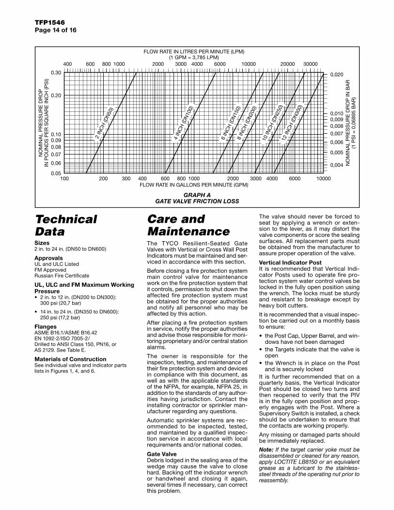
GRAPH A GATE VALVE FRICTION LOSS
TFP1546Page 15 of 16
Cross Wall Indicator PostIt is recommended that Cross Wall Indi-cator Posts used to operate fire pro-tection system water control valves be locked in the fully open position using the Handwheel. The locks must be sturdy and resistant to breakage except by heavy bolt cutters.
It is recommended that a visual inspec-tion be carried out on a monthly basis to ensure:
• the Post body, Handwheel, and win-dows have not been damaged
• the Targets indicate that the valve is open
• the Post is properly locked openIt is further recommended that on a quarterly basis, the Cross Wall Indi-cator Post should be closed two turns and then reopened to verify that the PIV is in the fully open position and prop-erly engages with the Post and that the Supervisory Switch contacts are working properly.
Any damaged parts should be immedi-ately replaced.
Note: If the target carrier yoke must be disassembled or cleaned for any reason, apply LOCTITE LB8150 or an equivalent grease as a lubricant to the stainless-steel threads of the operating nut prior to reassembly.
Limited WarrantyFor warranty terms and conditions, visit www.tyco-fire.com.
Ordering ProcedureContact your local distributor for avail-ability. When placing an order, indicate the full product name and Part Number (P/N).
Refer to Table B for Gate Valve part numbers and Table C for Vertical and Cross Wall Indicator Post part numbers.
Replacement Vertical Indicator Post WrenchAll Vertical Indicator Post types feature a removable wrench for operating the PIV. Replace as necessary.
Specify: Vertical Indicator Post Wrench, P/N TJUPWRENCH
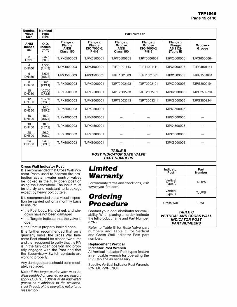
Nominal Valve Size
Nominal Pipe Size
Part Number
ANSI Inches
DN
O.D. Inches (mm)
Flange x Flange ANSI
Class 150
Flange x Flange
ISO 7005-2 PN16
Flange x Groove ANSI
Class 150
Flange x Groove
ISO 7005-2 PN16
Flange x Flange
AS 2129 (Table E)
Groove x Groove
2 DN50
2.375 (60.3) TJPX0500003 TJPX0500001 TJPT0500603 TJPT0500601 TJPX0500005 TJPG0500604
4 DN100
4.500 (114.3) TJPX1000003 TJPX1000001 TJPT1001143 TJPT1001141 TJPX1000005 TJPG1001144
6 DN150
6.625 (168.3) TJPX1500003 TJPX1500001 TJPT1501683 TJPT1501681 TJPX1500005 TJPG1501684
8 DN200
8.625 (219.1) TJPX2000003 TJPX2000001 TJPT2002193 TJPT2002191 TJPX2000005 TJPG2002194
10 DN250
10.750 (273.1) TJPX2500003 TJPX2500001 TJPT2502733 TJPT2502731 TJPX2500005 TJPG2502734
12 DN300
12.750 (323.9) TJPX3000003 TJPX3000001 TJPT3003243 TJPT3003241 TJPX3000005 TJPG3003244
14 DN350
14.0 (355.6) TJPX3500003 TJPX3500001 — — TJPX3500005 —
16 DN400
16.0 (406.4) TJPX4000003 TJPX4000001 — — TJPX4000005 —
18 DN450
18.0 (457.2) TJPX4500003 TJPX4500001 — — TJPX4500005 —
20 DN500
20.0 (508.0) TJPX5000003 TJPX5000001 — — TJPX5000005 —
24 DN600
24.0 (609.6) TJPX6000003 TJPX6000001 — — TJPX6000005 —
TABLE B POST INDICATOR GATE VALVE
PART NUMBERS
Indicator Post
Part Number
Vertical Type A TJUPA
Vertical Type B TJUPB
Cross Wall TJWP
TABLE C VERTICAL AND CROSS WALL
INDICATOR POST PART NUMBERS

TFP1546Page 16 of 16
NATIONAL FIRE PROTECTION ASSOCIATION and NFPA are registered trademarks of National Fire Protection Association;LOCTITE is a registered trademark of Henkel Corporation
1400 Pennbrook Parkway, Lansdale, PA 19446 | Telephone +1-215-362-0700
© 2021 Johnson Controls. All rights reserved. All specifications and other information shown were current as of document revision date and are subject to change without notice.