Embed Size (px)
Citation preview
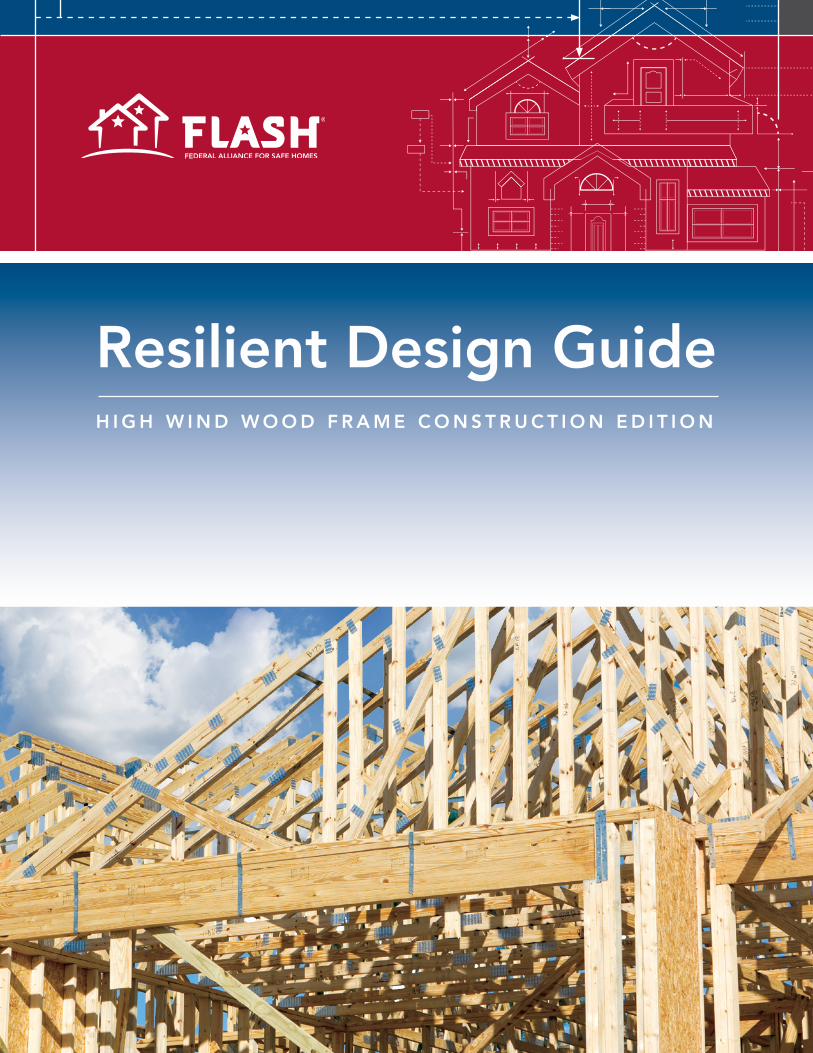
Resilient Design GuideH I G H W I N D W O O D F R A M E C O N S T R U C T I O N E D I T I O N
R E S I L I E N T D E S I G N G U I D E
1R E S I L I E N T D E S I G N G U I D E
The purpose of this Resilient Design Guide is to provide architects, designers or even homeowners the information necessary to make any set of house plans useful for constructing a more wind resilient structure.
The guide was developed during the course of a two-day charrette that brought together a cross-section of professionals from across the United States. The charrette allowed participants to tap into diverse knowledge and resources provided by professionals, including academics, architects, community outreach organizations, engineers, homebuilders, insurance professionals, manufacturers, product experts, and other building professionals with practical experience before and after high
wind disasters, including hurricanes and tornadoes. The group pooled their knowledge and experience to develop an outline for this guide with the goal to provide not only an overview of the “why,” but the “how to” of resilient wind construction. The authors sincerely appreciate the many dedicated professionals that supported this guide.
For more information, contact the Federal Alliance for Safe Homes (FLASH)® at (877)-221-SAFE or visit www.flash.org.
2 R E S I L I E N T D E S I G N G U I D E
Founded in 1857, members of the American Institute of Architects consistently work to create more valuable, healthy, secure, and sustainable buildings, neighborhoods, and communities. Through nearly 300 state and local chapters, the AIA advocates for public policies that promote economic vitality and public wellbeing. Members adhere to a code of ethics and conduct to ensure the highest professional standards. The AIA provides members with tools and resources to assist them in their careers and business as well as engaging civic and government leaders, and the public to find solutions to pressing issues facing our communities, institutions, nation and world. Visit www.aia.org.
The Gulf Coast Community Design Studio (GCCDS) is a professional service and outreach program of Mississippi State University’s College of Architecture, art + design. The GCCDS works through close, pragmatic partnerships with local organizations and communities, regional nonprofits, local governments, universities, developers and other partners across the country to help shape vibrant and resilient Gulf Coast communities. www.gccds.org
Mississippi State University
Architecture for Humanity is a nonprofit design services firm founded in 1999. By building a more sustainable future through the power of professional design, Architecture for Humanity taps a network of more than 55,000 professionals willing to lend time and expertise to help those who would not otherwise be able to afford their services. They bring design, construction and development services where they are most critically needed. To learn more about Architecture for Humanity and support their work, go to www.architectureforhumanity.org.
The nonprofit Federal Alliance for Safe Homes (FLASH)® is the country’s leading consumer advocate for strengthening homes and safeguarding families from natural and manmade disasters. The FLASH mission is to promote life safety, property protection and resilience by empowering the families with knowledge and resources for strengthening homes and safeguarding families from disasters of all kinds. www.flash.org
The Florida Association of the American Institute of Architects, headquartered in Tallahassee, represents the interests of more than 3,400 members in Florida. Members adhere to a code of ethics and professional conduct that assures the client, the public, and colleagues of an AIA-member architect's dedication to the highest standards in professional practice.
Founded in 1857, the AIA New York Chapter is the oldest and largest chapter of the American Institute of Architects. The Chapter's members include more than 5,000 practicing architects, allied professionals, students, and public members interested in architecture and design. The AIA New York Chapter is dedicated to three goals: design excellence, public outreach, and professional development.
3R E S I L I E N T D E S I G N G U I D E
High Wind Wood Frame ConstructionTwenty six percent (approximately 30 million) of U.S. households are in wind zones with an expected wind speed of 110 mph (3-second gust) or greater. Homes in these high wind zones should be designed and built to be strong and weather resistant to improve safety and reduce costly repairs following severe weather. To accomplish these goals, the structure must be designed with an engineered vertical and horizontal load path. That is to say, every component in that path should be engineered to resist a specific wind load. This guide illustrates high wind building design and construction practices, beyond code practices and prescriptive recommendations for this type of added resiliency.
Building CodesThe purpose of this guide is to provide information to designers and homebuilders about high wind construction while outlining options for enhanced resilience with affiliated costs and benefits. Building codes and practices vary throughout the U.S., so users of this guide should become familiar with local building codes and keep in mind that a home can be made more resilient by building beyond the building code. This guide will not detail all building code requirements, but will highlight beyond code and other proven ways to increase resilience.
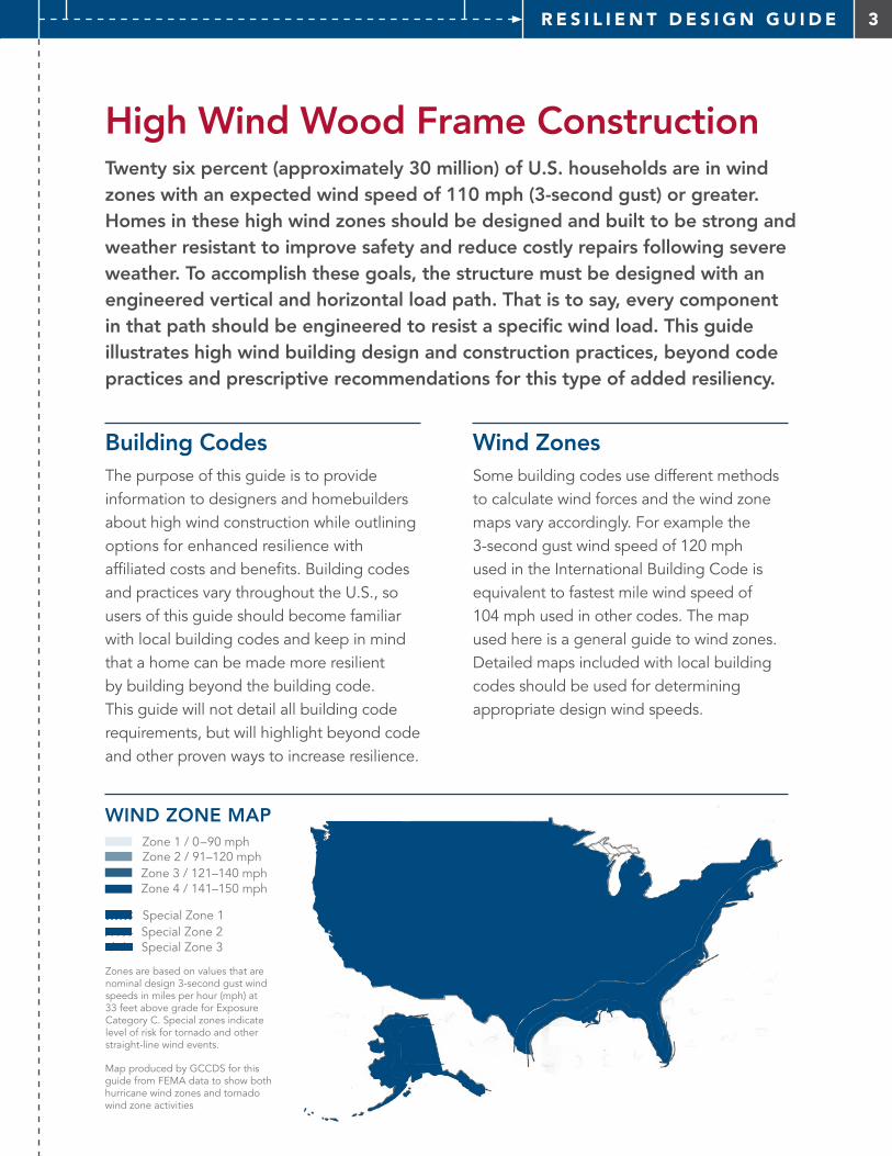
Wind ZonesSome building codes use different methods to calculate wind forces and the wind zone maps vary accordingly. For example the 3-second gust wind speed of 120 mph used in the International Building Code is equivalent to fastest mile wind speed of 104 mph used in other codes. The map used here is a general guide to wind zones. Detailed maps included with local building codes should be used for determining appropriate design wind speeds.
Special Zone 3
Special Zone 1Special Zone 2
Zone 4 / 141–150 mph
Zone 2 / 91–120 mphZone 3 / 121–140 mph
Zone 1 / 0–90 mph
Zones are based on values that are nominal design 3-second gust wind speeds in miles per hour (mph) at 33 feet above grade for Exposure Category C. Special zones indicate level of risk for tornado and other straight-line wind events.
Map produced by GCCDS for this guide from FEMA data to show both hurricane wind zones and tornado wind zone activities
WIND ZONE MAP
4 TA B L E O F C O N T E N T S
44Acknowledgements
42Appendix
18Walls
40Site
8Roof
32Foundation
5Introduction
Roof Walls Foundation Site
5I N T R O D U C T I O N
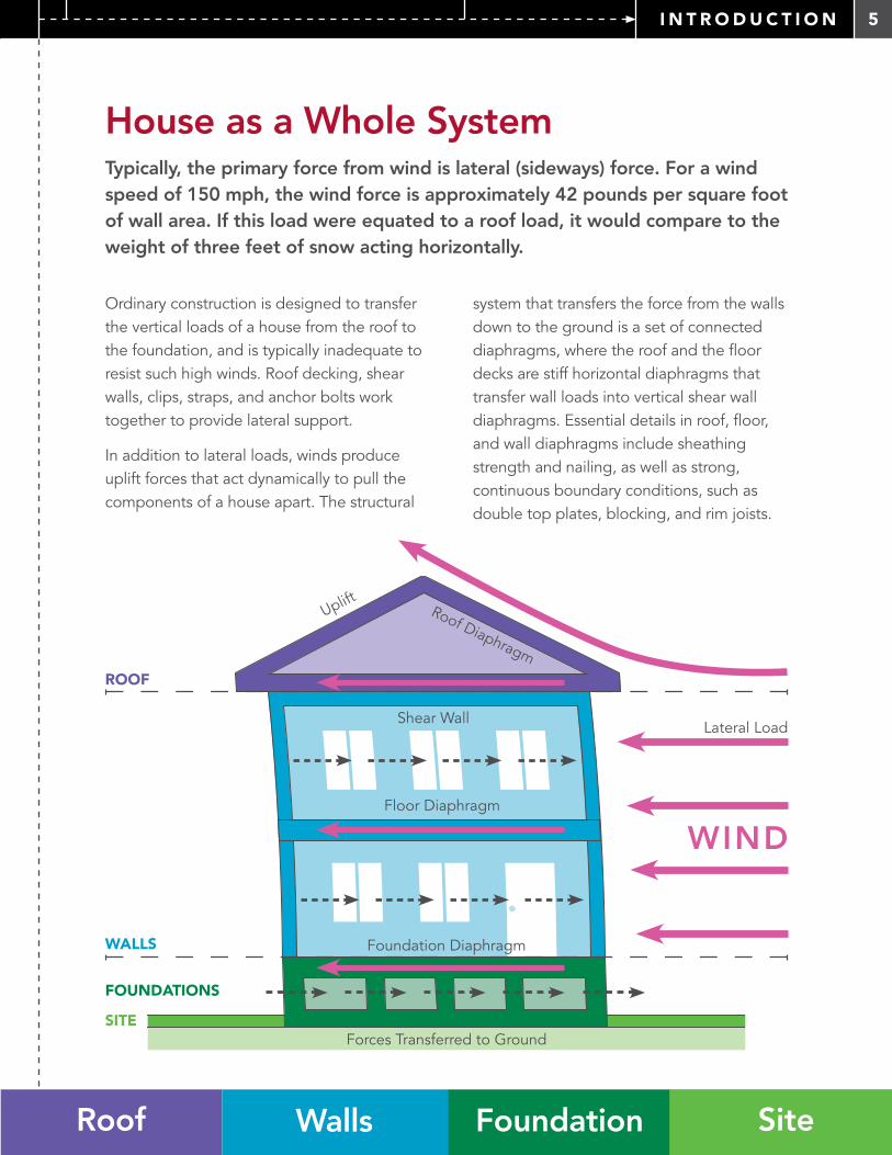
House as a Whole SystemTypically, the primary force from wind is lateral (sideways) force. For a wind speed of 150 mph, the wind force is approximately 42 pounds per square foot of wall area. If this load were equated to a roof load, it would compare to the weight of three feet of snow acting horizontally.
Ordinary construction is designed to transfer the vertical loads of a house from the roof to the foundation, and is typically inadequate to resist such high winds. Roof decking, shear walls, clips, straps, and anchor bolts work together to provide lateral support.
In addition to lateral loads, winds produce uplift forces that act dynamically to pull the components of a house apart. The structural
system that transfers the force from the walls down to the ground is a set of connected diaphragms, where the roof and the floor decks are stiff horizontal diaphragms that transfer wall loads into vertical shear wall diaphragms. Essential details in roof, floor, and wall diaphragms include sheathing strength and nailing, as well as strong, continuous boundary conditions, such as double top plates, blocking, and rim joists.
WIND
Uplift
Lateral LoadShear Wall
Roof Diaphragm
Floor Diaphragm
Forces Transferred to Ground
ROOF
WALLS
FOUNDATIONS
SITE
Foundation Diaphragm
6 I N T R O D U C T I O N
7I N T R O D U C T I O N
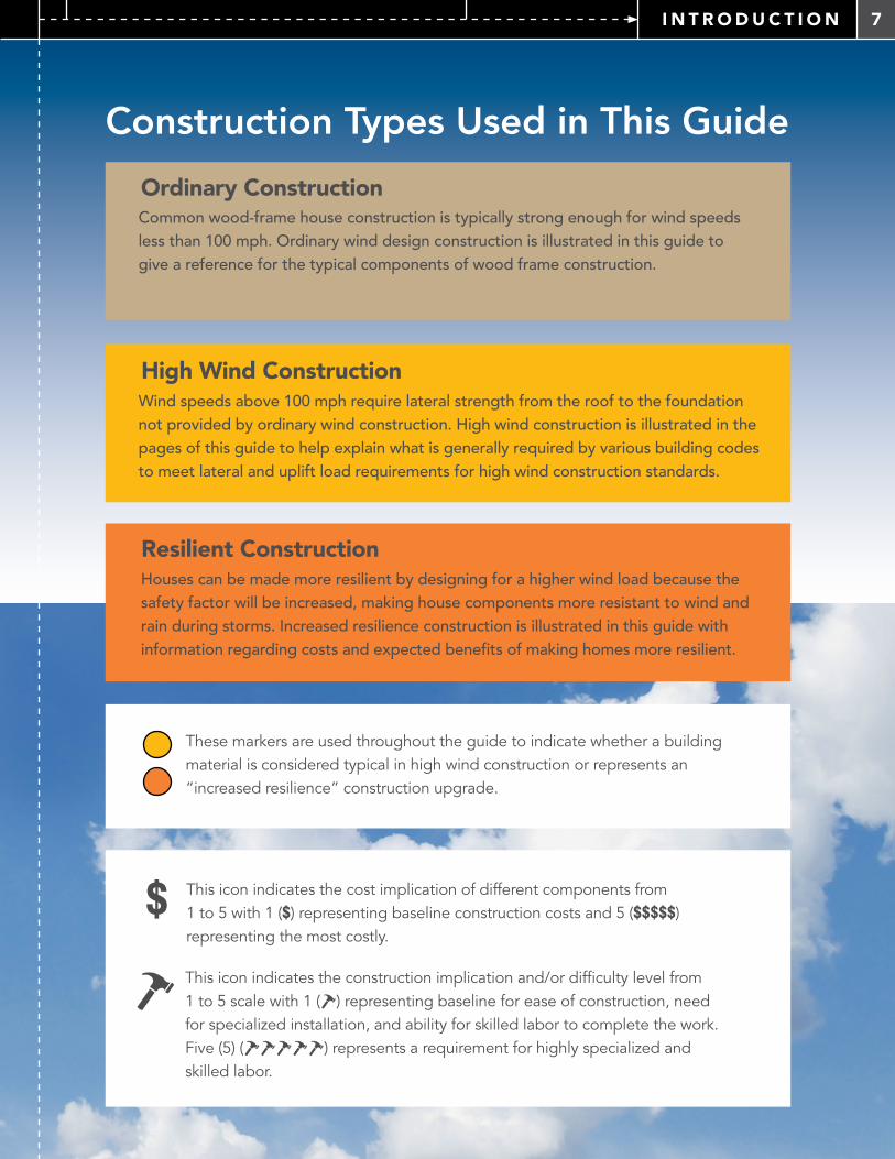
This icon indicates the construction implication and/or difficulty level from 1 to 5 scale with 1 ( ) representing baseline for ease of construction, need for specialized installation, and ability for skilled labor to complete the work. Five (5) ( ) represents a requirement for highly specialized and skilled labor.
This icon indicates the cost implication of different components from 1 to 5 with 1 ($) representing baseline construction costs and 5 ($$$$$) representing the most costly.
$
Ordinary ConstructionCommon wood-frame house construction is typically strong enough for wind speeds less than 100 mph. Ordinary wind design construction is illustrated in this guide to give a reference for the typical components of wood frame construction.
High Wind ConstructionWind speeds above 100 mph require lateral strength from the roof to the foundation not provided by ordinary wind construction. High wind construction is illustrated in the pages of this guide to help explain what is generally required by various building codes to meet lateral and uplift load requirements for high wind construction standards.
Resilient ConstructionHouses can be made more resilient by designing for a higher wind load because the safety factor will be increased, making house components more resistant to wind and rain during storms. Increased resilience construction is illustrated in this guide with information regarding costs and expected benefits of making homes more resilient.
Construction Types Used in This Guide
These markers are used throughout the guide to indicate whether a building material is considered typical in high wind construction or represents an “increased resilience” construction upgrade.
8 R O O F
How a Roof Works in Wind
OVERHEAD VIEW OF ROOF
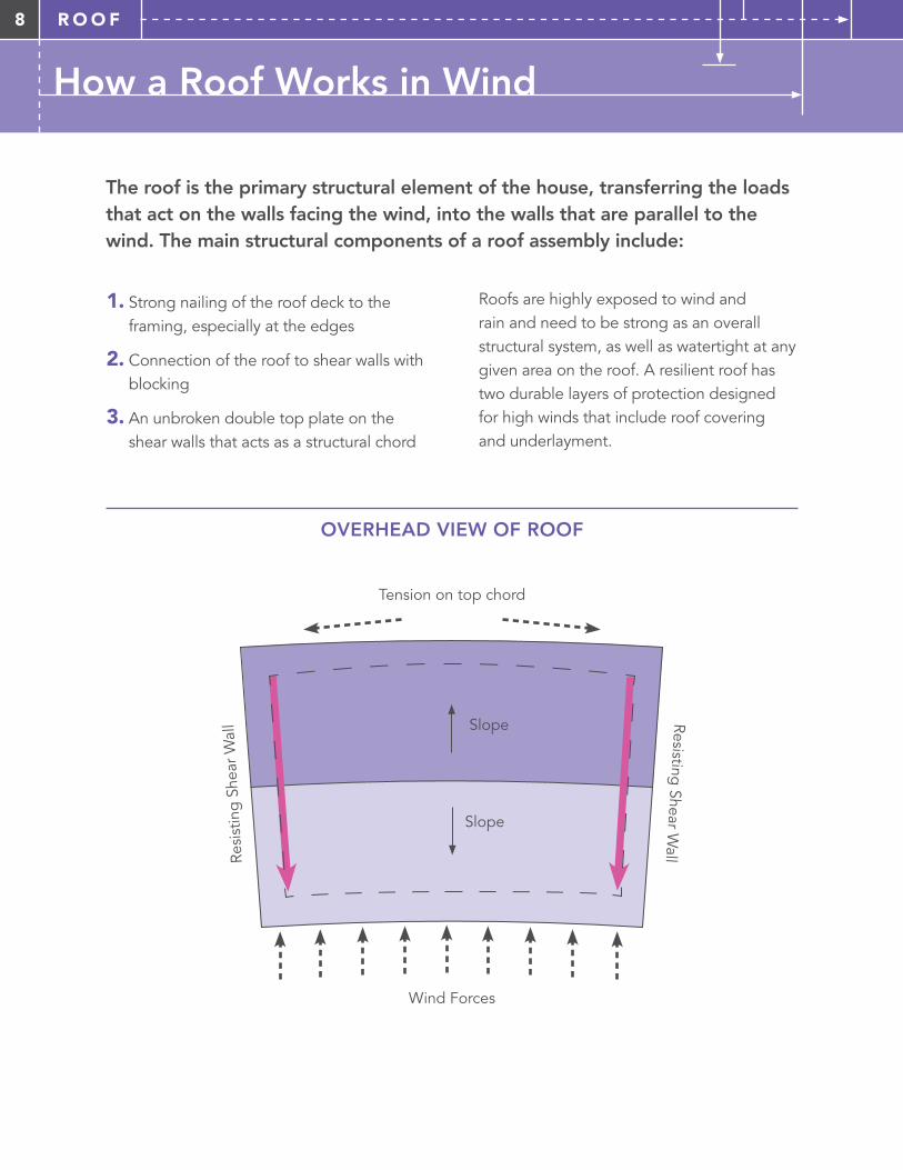
The roof is the primary structural element of the house, transferring the loads that act on the walls facing the wind, into the walls that are parallel to the wind. The main structural components of a roof assembly include:
1. Strong nailing of the roof deck to the framing, especially at the edges
2. Connection of the roof to shear walls with blocking
3. An unbroken double top plate on the shear walls that acts as a structural chord
Roofs are highly exposed to wind and rain and need to be strong as an overall structural system, as well as watertight at any given area on the roof. A resilient roof has two durable layers of protection designed for high winds that include roof covering and underlayment.
Slope
Slope
Tension on top chord
Resisting Shear W
all
Wind Forces
Resi
stin
g S
hear
Wal
l
9R O O F
Roof Components
COVERINGS
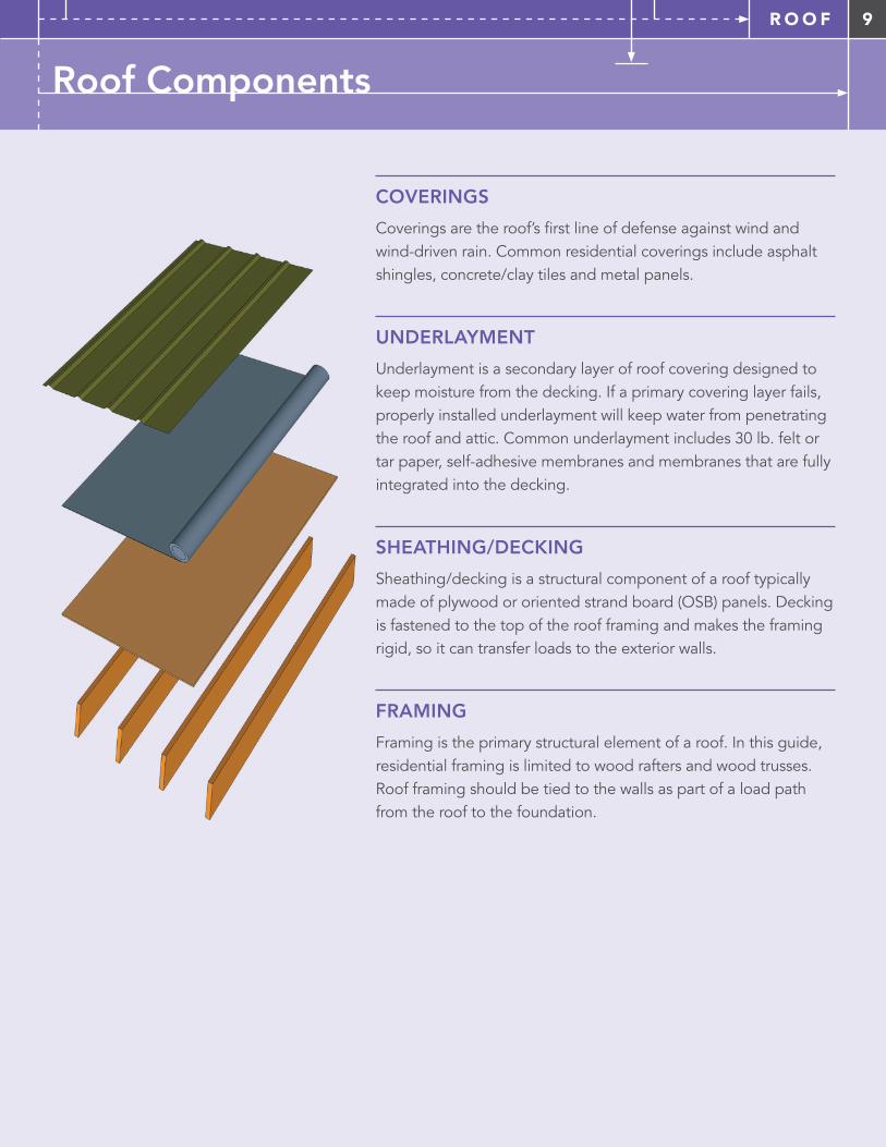
Coverings are the roof’s first line of defense against wind and wind-driven rain. Common residential coverings include asphalt shingles, concrete/clay tiles and metal panels.
UNDERLAYMENT
Underlayment is a secondary layer of roof covering designed to keep moisture from the decking. If a primary covering layer fails, properly installed underlayment will keep water from penetrating the roof and attic. Common underlayment includes 30 lb. felt or tar paper, self-adhesive membranes and membranes that are fully integrated into the decking.
SHEATHING/DECKING
Sheathing/decking is a structural component of a roof typically made of plywood or oriented strand board (OSB) panels. Decking is fastened to the top of the roof framing and makes the framing rigid, so it can transfer loads to the exterior walls.
FRAMING
Framing is the primary structural element of a roof. In this guide, residential framing is limited to wood rafters and wood trusses. Roof framing should be tied to the walls as part of a load path from the roof to the foundation.
10 R O O F
ROOF COMPONENTS
Ordinary Construction
High Wind Construction
Resilient Construction
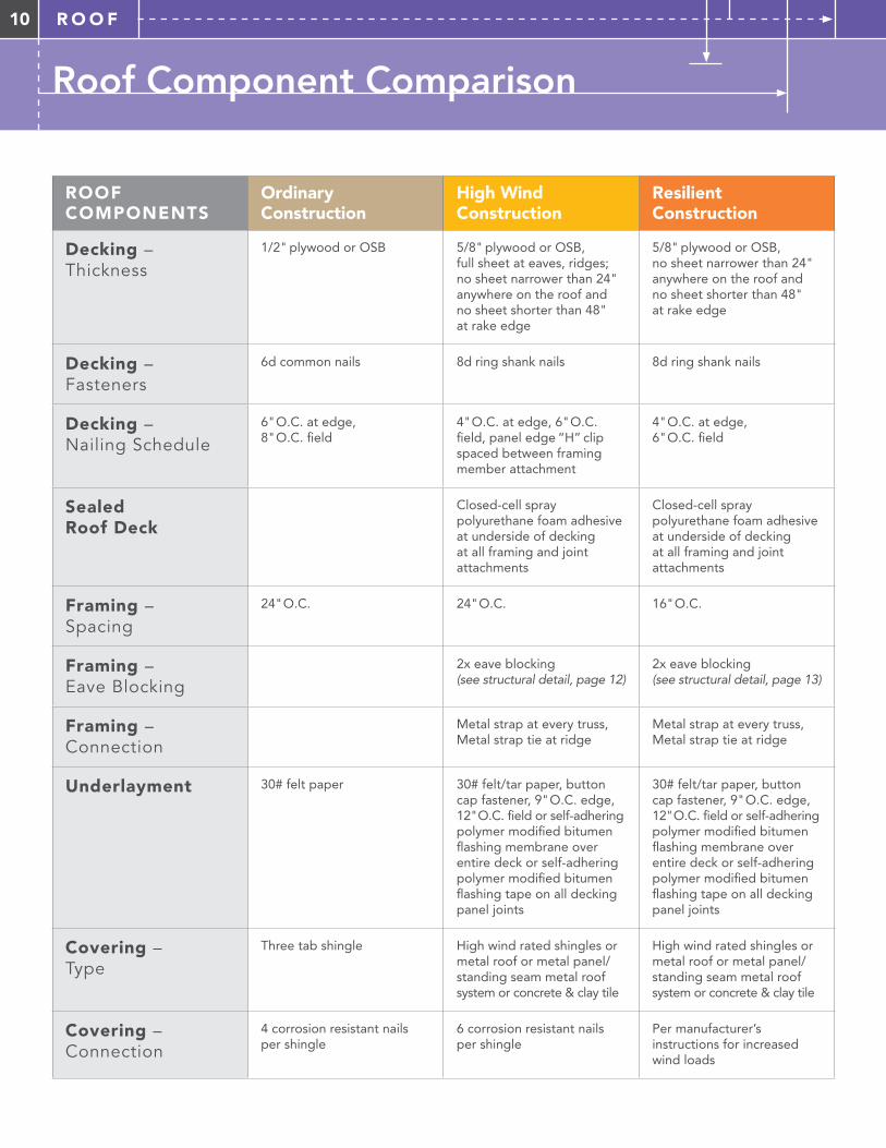
Decking – Thickness
1/2" plywood or OSB 5/8" plywood or OSB, full sheet at eaves, ridges; no sheet narrower than 24" anywhere on the roof and no sheet shorter than 48" at rake edge
5/8" plywood or OSB, no sheet narrower than 24" anywhere on the roof and no sheet shorter than 48" at rake edge
Decking – Fasteners
6d common nails 8d ring shank nails 8d ring shank nails
Decking – Nailing Schedule
6" O.C. at edge, 8" O.C. field
4" O.C. at edge, 6" O.C. field, panel edge “H” clip spaced between framing member attachment
4" O.C. at edge, 6" O.C. field
Sealed Roof Deck
Closed-cell spray polyurethane foam adhesive at underside of decking at all framing and joint attachments
Closed-cell spray polyurethane foam adhesive at underside of decking at all framing and joint attachments
Framing – Spacing
24" O.C. 24" O.C. 16" O.C.
Framing – Eave Blocking
2x eave blocking (see structural detail, page 12)
2x eave blocking (see structural detail, page 13)
Framing – Connection
Metal strap at every truss, Metal strap tie at ridge
Metal strap at every truss, Metal strap tie at ridge
Underlayment 30# felt paper 30# felt/tar paper, button cap fastener, 9" O.C. edge, 12" O.C. field or self-adhering polymer modified bitumen flashing membrane over entire deck or self-adhering polymer modified bitumen flashing tape on all decking panel joints
30# felt/tar paper, button cap fastener, 9" O.C. edge, 12" O.C. field or self-adhering polymer modified bitumen flashing membrane over entire deck or self-adhering polymer modified bitumen flashing tape on all decking panel joints
Covering – Type
Three tab shingle High wind rated shingles or metal roof or metal panel/standing seam metal roof system or concrete & clay tile
High wind rated shingles or metal roof or metal panel/standing seam metal roof system or concrete & clay tile
Covering – Connection
4 corrosion resistant nails per shingle
6 corrosion resistant nails per shingle
Per manufacturer’s instructions for increased wind loads
Roof Component Comparison
11R O O F
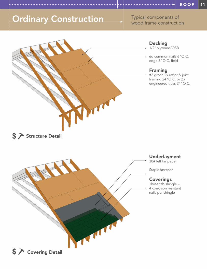
Typical components of wood frame constructionOrdinary Construction
Decking1/2" plywood/OSB
6d common nails 6" O.C. edge 8" O.C. field
Framing #2 grade 2x rafter & joist framing 24" O.C. or 2x engineered truss 24" O.C.
Underlayment30# felt tar paper
Staple fastener
Coverings Three tab shingle – 4 corrosion resistant nails per shingle
$ Covering Detail
$ Structure Detail
12 R O O F
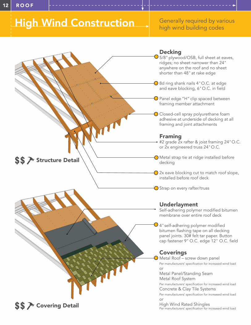
High Wind Construction Generally required by various high wind building codesHigh Wind Construction
Framing #2 grade 2x rafter & joist framing 24" O.C. or 2x engineered truss 24" O.C.
Metal strap tie at ridge installed before decking
2x eave blocking cut to match roof slope, installed before roof deck
Strap on every rafter/truss
Decking5/8" plywood/OSB, full sheet at eaves, ridges; no sheet narrower than 24" anywhere on the roof and no sheet shorter than 48" at rake edge
8d ring shank nails 4" O.C. at edge and eave blocking, 6" O.C. in field
Panel edge “H” clip spaced between framing member attachment
Closed-cell spray polyurethane foam adhesive at underside of decking at all framing and joint attachments
UnderlaymentSelf-adhering polymer modified bitumen membrane over entire roof deck
4" self-adhering polymer modified bitumen flashing tape on all decking panel joints. 30# felt tar paper. Button cap fastener 9" O.C. edge 12" O.C. field
Coverings Metal Roof – screw down panelPer manufacturers’ specification for increased wind load
or Metal Panel/Standing Seam Metal Roof SystemPer manufacturers’ specification for increased wind load
Concrete & Clay Tile SystemsPer manufacturers’ specification for increased wind load
or High Wind Rated ShinglesPer manufacturers’ specification for increased wind load$$ Covering Detail
$$ Structure Detail
13R O O F
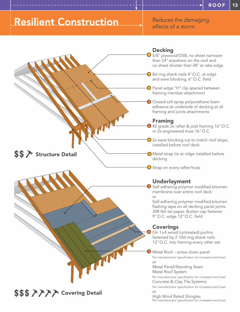
Resilient Construction Reduces the damaging effects of a stormResilient Construction Reduces the damaging effects of a storm
Decking5/8" plywood/OSB, no sheet narrower than 24" anywhere on the roof and no sheet shorter than 48" at rake edge
8d ring shank nails 4" O.C. at edge and eave blocking, 6" O.C. field
Panel edge “H” clip spaced between framing member attachment
Closed-cell spray polyurethane foam adhesive at underside of decking at all framing and joints attachments
Framing #2 grade 2x rafter & joist framing 16" O.C. or 2x engineered truss 16" O.C.
2x eave blocking cut to match roof slope, installed before roof deck
Metal strap tie at ridge installed before decking
Strap on every rafter/truss
UnderlaymentSelf-adhering polymer modified bitumen membrane over entire roof deck orSelf-adhering polymer modified bitumen flashing tape on all decking panel joints. 30# felt tar paper. Button cap fastener 9" O.C. edge 12" O.C. field
Coverings On 1x4 wood (untreated) purlins fastened by 2 10d ring shank nails 12" O.C. into framing every other set
Metal Roof – screw down panel Per manufacturers’ specification for increased wind load
or Metal Panel/Standing Seam Metal Roof SystemPer manufacturers’ specification for increased wind load
Concrete & Clay Tile SystemsPer manufacturers’ specification for increased wind load
or High Wind Rated ShinglesPer manufacturers’ specification for increased wind load
$$$ Covering Detail
$$ Structure Detail
14 R O O F
Supplemental Information – Roof
H A Z A R D S
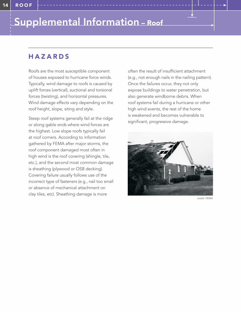
Roofs are the most susceptible component of houses exposed to hurricane force winds. Typically, wind damage to roofs is caused by uplift forces (vertical), suctional and torsional forces (twisting), and horizontal pressures. Wind damage effects vary depending on the roof height, slope, siting and style.
Steep roof systems generally fail at the ridge or along gable ends where wind forces are the highest. Low slope roofs typically fail at roof corners. According to information gathered by FEMA after major storms, the roof component damaged most often in high wind is the roof covering (shingle, tile, etc.), and the second most common damage is sheathing (plywood or OSB decking). Covering failure usually follows use of the incorrect type of fasteners (e.g., nail too small or absence of mechanical attachment on clay tiles, etc). Sheathing damage is more
often the result of insufficient attachment (e.g., not enough nails in the nailing pattern). Once the failures occur, they not only expose buildings to water penetration, but also generate windborne debris. When roof systems fail during a hurricane or other high wind events, the rest of the home is weakened and becomes vulnerable to significant, progressive damage.
credit: FEMA
15R O O F
Underlayment should be securely fastened to roof decking independently of the roof covering fasteners. Staples are sometimes used to fasten underlayment materials such as felt/tar paper based on the assumption that fasteners used to apply roof shingles on top will secure the underlayment. Unfortunately, in a high wind zone, roof shingles are often lost and this leaves inadequately attached underlayment that cannot prevent water intrusion through deck joints or nail
holes. Using a fastener such as a button cap to secure the underlayment will help prevent water intrusion should the coverings fail. Peel-and-stick membrane products also offer superior protection when coverings are lost. Shingles are more wind resistant overall when installed using six versus four nails. Metal and clay tile roof systems should always be attached using manufacturers’ specifications for an increased wind load.
Supplemental Information – Roof
R I D G E S , VA L L E Y S A N D A C C E S S O R I E S
U N D E R L AY M E N T A N D C O V E R I N G S
Roof ridges often experience covering loss in hurricanes or severe windstorms, and vented ridge caps should be properly fastened to ensure adequate resistance. Low profile ridge vents are a good choice as they are less vulnerable in high wind events. Roof valleys are vulnerable in severe weather because
they experience significant water flow that can lead to water infiltration. Special care should be taken to follow manufacturers’ specifications to attach all roof elements, including accessories, equipment, solar panels and/or turbine roof vents.
16 R O O F
Supplemental Information – Roof
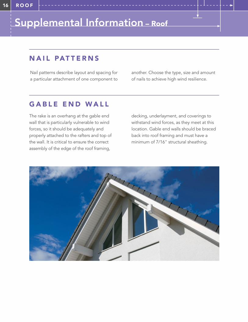
N A I L PAT T E R N S
Nail patterns describe layout and spacing for a particular attachment of one component to
G A B L E E N D W A L L
The rake is an overhang at the gable end wall that is particularly vulnerable to wind forces, so it should be adequately and properly attached to the rafters and top of the wall. It is critical to ensure the correct assembly of the edge of the roof framing,
decking, underlayment, and coverings to withstand wind forces, as they meet at this location. Gable end walls should be braced back into roof framing and must have a minimum of 7/16" structural sheathing.
another. Choose the type, size and amount of nails to achieve high wind resilience.
17R O O F
Roof Connections
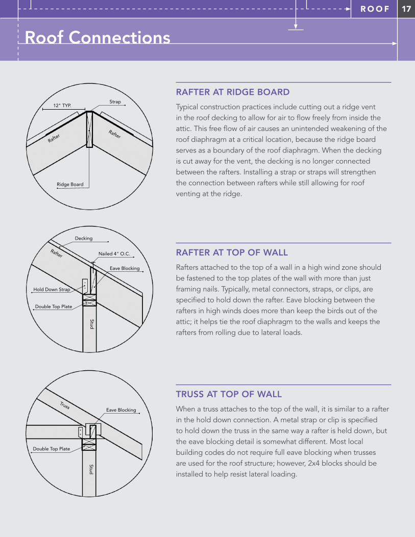
RAFTER AT RIDGE BOARD
Typical construction practices include cutting out a ridge vent in the roof decking to allow for air to flow freely from inside the attic. This free flow of air causes an unintended weakening of the roof diaphragm at a critical location, because the ridge board serves as a boundary of the roof diaphragm. When the decking is cut away for the vent, the decking is no longer connected between the rafters. Installing a strap or straps will strengthen the connection between rafters while still allowing for roof venting at the ridge.
RAFTER AT TOP OF WALL
Rafters attached to the top of a wall in a high wind zone should be fastened to the top plates of the wall with more than just framing nails. Typically, metal connectors, straps, or clips, are specified to hold down the rafter. Eave blocking between the rafters in high winds does more than keep the birds out of the attic; it helps tie the roof diaphragm to the walls and keeps the rafters from rolling due to lateral loads.
TRUSS AT TOP OF WALL
When a truss attaches to the top of the wall, it is similar to a rafter in the hold down connection. A metal strap or clip is specified to hold down the truss in the same way a rafter is held down, but the eave blocking detail is somewhat different. Most local building codes do not require full eave blocking when trusses are used for the roof structure; however, 2x4 blocks should be installed to help resist lateral loading.
12" TYP. Strap
Ridge Board
Rafter Rafte
r
Double Top Plate
Hold Down Strap
Rafter
Stud
Eave Blocking
Decking
Nailed 4" O.C.
Double Top Plate
Truss
Stud
Eave Blocking
18 W A L L S
How a Wall Works in Wind
ELEVATION VIEW OF WALL
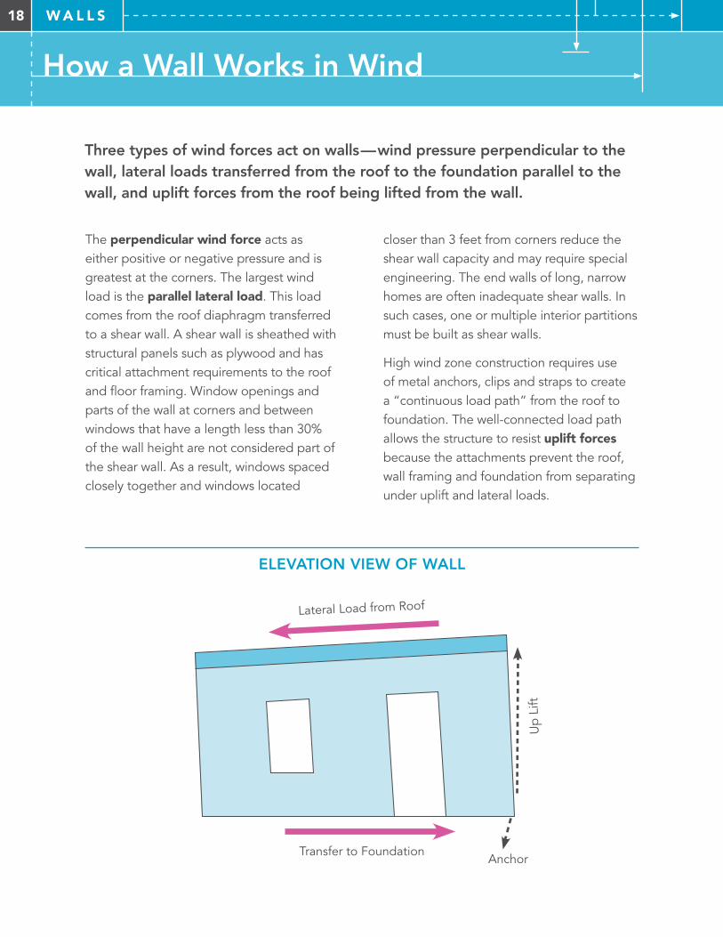
Three types of wind forces act on walls—wind pressure perpendicular to the wall, lateral loads transferred from the roof to the foundation parallel to the wall, and uplift forces from the roof being lifted from the wall.
The perpendicular wind force acts as either positive or negative pressure and is greatest at the corners. The largest wind load is the parallel lateral load. This load comes from the roof diaphragm transferred to a shear wall. A shear wall is sheathed with structural panels such as plywood and has critical attachment requirements to the roof and floor framing. Window openings and parts of the wall at corners and between windows that have a length less than 30% of the wall height are not considered part of the shear wall. As a result, windows spaced closely together and windows located
closer than 3 feet from corners reduce the shear wall capacity and may require special engineering. The end walls of long, narrow homes are often inadequate shear walls. In such cases, one or multiple interior partitions must be built as shear walls.
High wind zone construction requires use of metal anchors, clips and straps to create a “continuous load path” from the roof to foundation. The well-connected load path allows the structure to resist uplift forces because the attachments prevent the roof, wall framing and foundation from separating under uplift and lateral loads.
Transfer to Foundation
Lateral Load from Roof
Up
Lift
Anchor
19W A L L S
Wall Components
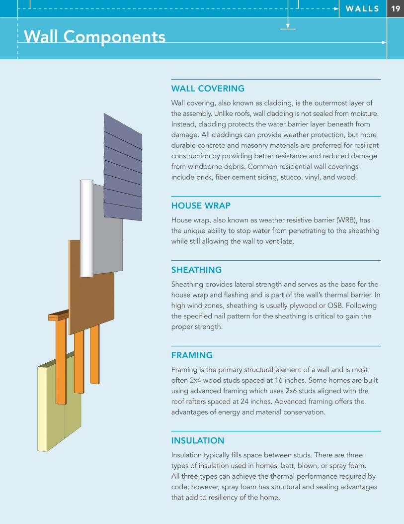
WALL COVERING
Wall covering, also known as cladding, is the outermost layer of the assembly. Unlike roofs, wall cladding is not sealed from moisture. Instead, cladding protects the water barrier layer beneath from damage. All claddings can provide weather protection, but more durable concrete and masonry materials are preferred for resilient construction by providing better resistance and reduced damage from windborne debris. Common residential wall coverings include brick, fiber cement siding, stucco, vinyl, and wood.
HOUSE WRAP
House wrap, also known as weather resistive barrier (WRB), has the unique ability to stop water from penetrating to the sheathing while still allowing the wall to ventilate.
SHEATHING
Sheathing provides lateral strength and serves as the base for the house wrap and flashing and is part of the wall’s thermal barrier. In high wind zones, sheathing is usually plywood or OSB. Following the specified nail pattern for the sheathing is critical to gain the proper strength.
FRAMING
Framing is the primary structural element of a wall and is most often 2x4 wood studs spaced at 16 inches. Some homes are built using advanced framing which uses 2x6 studs aligned with the roof rafters spaced at 24 inches. Advanced framing offers the advantages of energy and material conservation.
INSULATION
Insulation typically fills space between studs. There are three types of insulation used in homes: batt, blown, or spray foam. All three types can achieve the thermal performance required by code; however, spray foam has structural and sealing advantages that add to resiliency of the home.
20 W A L L S
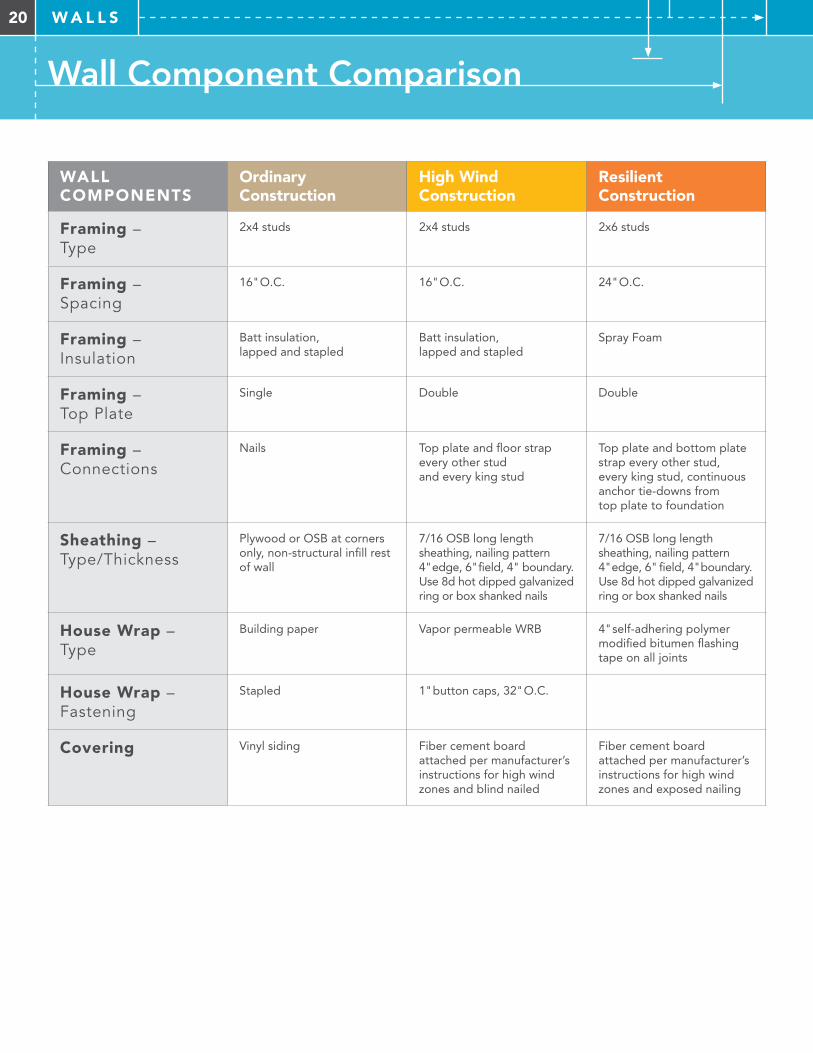
WALL COMPONENTS
Ordinary Construction
High Wind Construction
Resilient Construction
Framing – Type
2x4 studs 2x4 studs 2x6 studs
Framing – Spacing
16" O.C. 16" O.C. 24" O.C.
Framing – Insulation
Batt insulation, lapped and stapled
Batt insulation, lapped and stapled
Spray Foam
Framing – Top Plate
Single Double Double
Framing – Connections
Nails Top plate and floor strap every other stud and every king stud
Top plate and bottom plate strap every other stud, every king stud, continuous anchor tie-downs from top plate to foundation
Sheathing – Type/Thickness
Plywood or OSB at corners only, non-structural infill rest of wall
7/16 OSB long length sheathing, nailing pattern 4" edge, 6" field, 4" boundary. Use 8d hot dipped galvanized ring or box shanked nails
7/16 OSB long length sheathing, nailing pattern 4" edge, 6" field, 4" boundary. Use 8d hot dipped galvanized ring or box shanked nails
House Wrap – Type
Building paper Vapor permeable WRB 4" self-adhering polymer modified bitumen flashing tape on all joints
House Wrap – Fastening
Stapled 1" button caps, 32" O.C.
Covering Vinyl siding Fiber cement board attached per manufacturer’s instructions for high wind zones and blind nailed
Fiber cement board attached per manufacturer’s instructions for high wind zones and exposed nailing
Wall Component Comparison
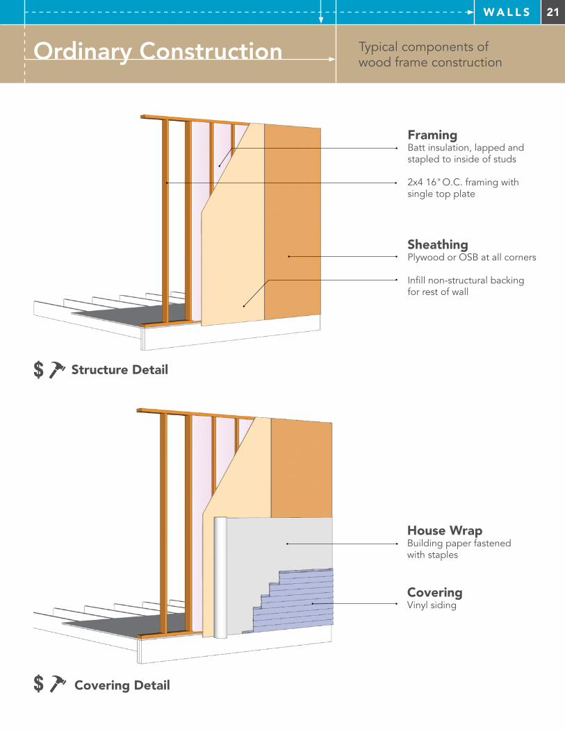
21W A L L S
Typical components of wood frame constructionOrdinary Construction
Framing Batt insulation, lapped and stapled to inside of studs
2x4 16" O.C. framing with single top plate
Sheathing Plywood or OSB at all corners
Infill non-structural backing for rest of wall
House WrapBuilding paper fastened with staples
Covering Vinyl siding
$ Covering Detail
$ Structure Detail
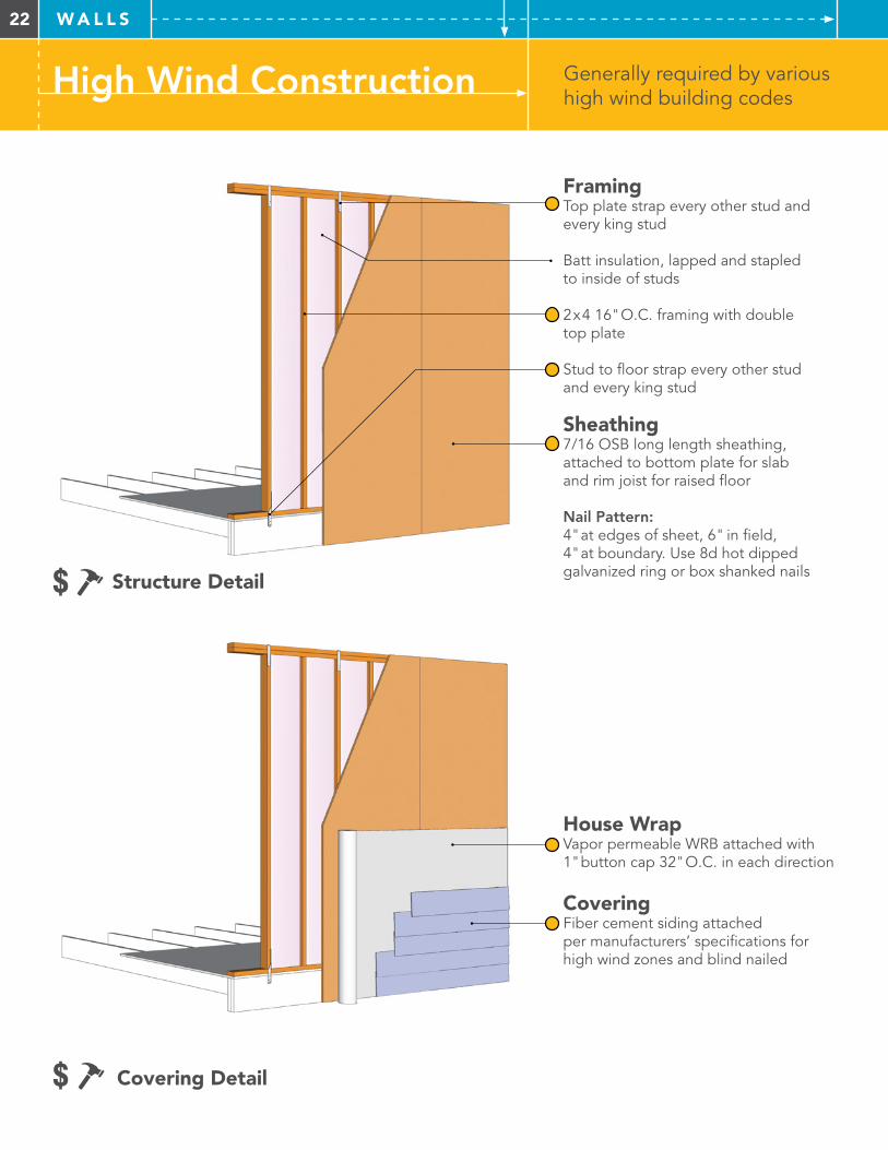
22 W A L L S
High Wind Construction Generally required by various high wind building codes
Framing Top plate strap every other stud and every king stud
Batt insulation, lapped and stapled to inside of studs
2x4 16" O.C. framing with double top plate
Stud to floor strap every other stud and every king stud
Sheathing 7/16 OSB long length sheathing, attached to bottom plate for slab and rim joist for raised floor
Nail Pattern: 4" at edges of sheet, 6" in field, 4" at boundary. Use 8d hot dipped galvanized ring or box shanked nails
House WrapVapor permeable WRB attached with 1" button cap 32" O.C. in each direction
Covering Fiber cement siding attached per manufacturers’ specifications for high wind zones and blind nailed
$ Covering Detail
$ Structure Detail
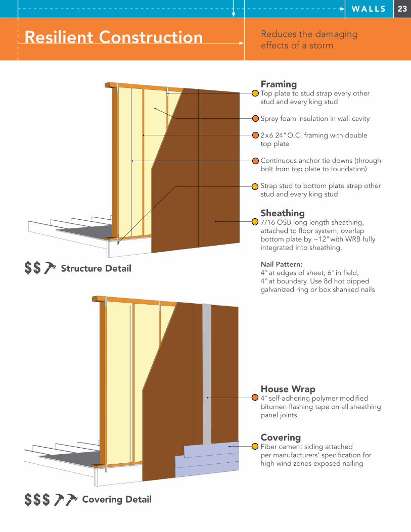
23W A L L S
Resilient Construction Reduces the damaging effects of a storm
Framing Top plate to stud strap every otherstud and every king stud
Spray foam insulation in wall cavity
2x6 24" O.C. framing with double top plate
Continuous anchor tie downs (through bolt from top plate to foundation)
Strap stud to bottom plate strap other stud and every king stud
Sheathing 7/16 OSB long length sheathing, attached to floor system, overlap bottom plate by ~12" with WRB fully integrated into sheathing.
Nail Pattern: 4" at edges of sheet, 6" in field, 4" at boundary. Use 8d hot dipped galvanized ring or box shanked nails
House Wrap4" self-adhering polymer modified bitumen flashing tape on all sheathing panel joints
Covering Fiber cement siding attached per manufacturers’ specification for high wind zones exposed nailing
$$$ Covering Detail
$$ Structure Detail
24 W A L L S
Supplemental Information – Walls
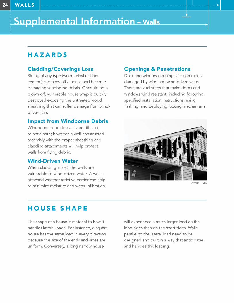
Openings & Penetrations Door and window openings are commonly damaged by wind and wind-driven water. There are vital steps that make doors and windows wind resistant, including following specified installation instructions, using flashing, and deploying locking mechanisms.
H A Z A R D S
H O U S E S H A P E
Cladding/Coverings Loss Siding of any type (wood, vinyl or fiber cement) can blow off a house and become damaging windborne debris. Once siding is blown off, vulnerable house wrap is quickly destroyed exposing the untreated wood sheathing that can suffer damage from wind-driven rain.
Impact from Windborne DebrisWindborne debris impacts are difficult to anticipate; however, a well-constructed assembly with the proper sheathing and cladding attachments will help protect walls from flying debris.
Wind-Driven Water When cladding is lost, the walls are vulnerable to wind-driven water. A well-attached weather resistive barrier can help to minimize moisture and water infiltration.
The shape of a house is material to how it handles lateral loads. For instance, a square house has the same load in every direction because the size of the ends and sides are uniform. Conversely, a long narrow house
will experience a much larger load on the long sides than on the short sides. Walls parallel to the lateral load need to be designed and built in a way that anticipates and handles this loading.
credit: FEMA
25W A L L S
Supplemental Information – Walls
S H E A R W A L L S
E AV E B L O C K I N G
Shear walls are structural walls that resist lateral forces acting on a house, and structural panels and framing are the primary components of a shear wall. In high wind zones, exterior walls are typically shear walls. In some cases, interior walls are designed as shear walls if the configuration of the home or size of openings requires more rigidity. Openings create weak points in shear walls and the shear wall strength is discounted for openings. Shear wall design is based on the height and length of a wall,
The method of eave blocking is a significant difference between typical construction and high wind zone construction. Typical eave blocking is commonly referred to as “bird blocking”. However, proper blocking between joists performs an essential function
the number and size of openings and the calculated lateral loads based on the specific wind zone location of the home. Shear walls have typical diaphragm nail patterns, e.g., 4" O.C. at edges and 6" O.C. in field. The shear walls must be properly attached to the roof and floor structure in order to properly transfer the loads to the foundation. Interior shear walls should attach to floor/foundation systems much like exterior walls attach to floor/foundation systems.
as it transfers lateral loads from the roof deck to the shear walls. Eave blocking should be installed during framing before the roof decking is in place. Roof decking should be nailed to the blocking before underlayment is installed.
26 W A L L S
Supplemental Information – Walls
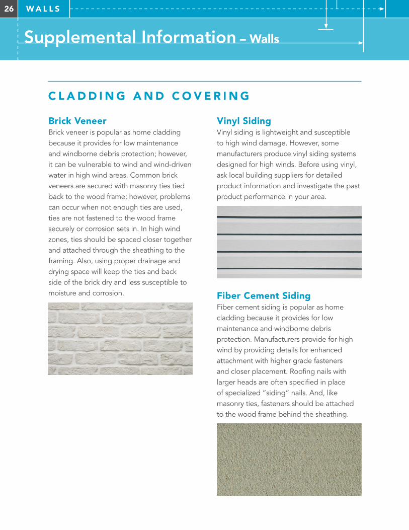
Vinyl SidingVinyl siding is lightweight and susceptible to high wind damage. However, some manufacturers produce vinyl siding systems designed for high winds. Before using vinyl, ask local building suppliers for detailed product information and investigate the past product performance in your area.
Fiber Cement Siding Fiber cement siding is popular as home cladding because it provides for low maintenance and windborne debris protection. Manufacturers provide for high wind by providing details for enhanced attachment with higher grade fasteners and closer placement. Roofing nails with larger heads are often specified in place of specialized “siding” nails. And, like masonry ties, fasteners should be attached to the wood frame behind the sheathing.
C L A D D I N G A N D C O V E R I N G
Brick VeneerBrick veneer is popular as home cladding because it provides for low maintenance and windborne debris protection; however, it can be vulnerable to wind and wind-driven water in high wind areas. Common brick veneers are secured with masonry ties tied back to the wood frame; however, problems can occur when not enough ties are used, ties are not fastened to the wood frame securely or corrosion sets in. In high wind zones, ties should be spaced closer together and attached through the sheathing to the framing. Also, using proper drainage and drying space will keep the ties and back side of the brick dry and less susceptible to moisture and corrosion.
27W A L L S
Supplemental Information – Windows
D E S I G N P R E S S U R E ( D P ) R AT I N G S
Design Pressure (DP) ratings on windows should not be confused with impact ratings as they are based solely on the wind load the windows are designed to withstand. DP ratings and requirements vary by the home’s wind zone location as well as window
location in the wall. For example, DP rating requirements in the middle of the wall where pressure is lower than those near the edges where pressure is greater. Refer to your local building authority to identify appropriate DP Ratings.
I M PA C T W I N D O W S
Impact-resistant windows are tested and rated with large and small missile impacts. Windows are required to remain intact after impact; however, glass breakage is allowed as along as the glass does not fall out of the window.
Large Missile 6' nine lb. 2x4 fired at 50FT/S Small Missile 30 pieces of roof gravel fired at 80FT/S
When local building codes in high wind zones require impact-resistant windows, they often allow for product substitutions due to cost considerations.
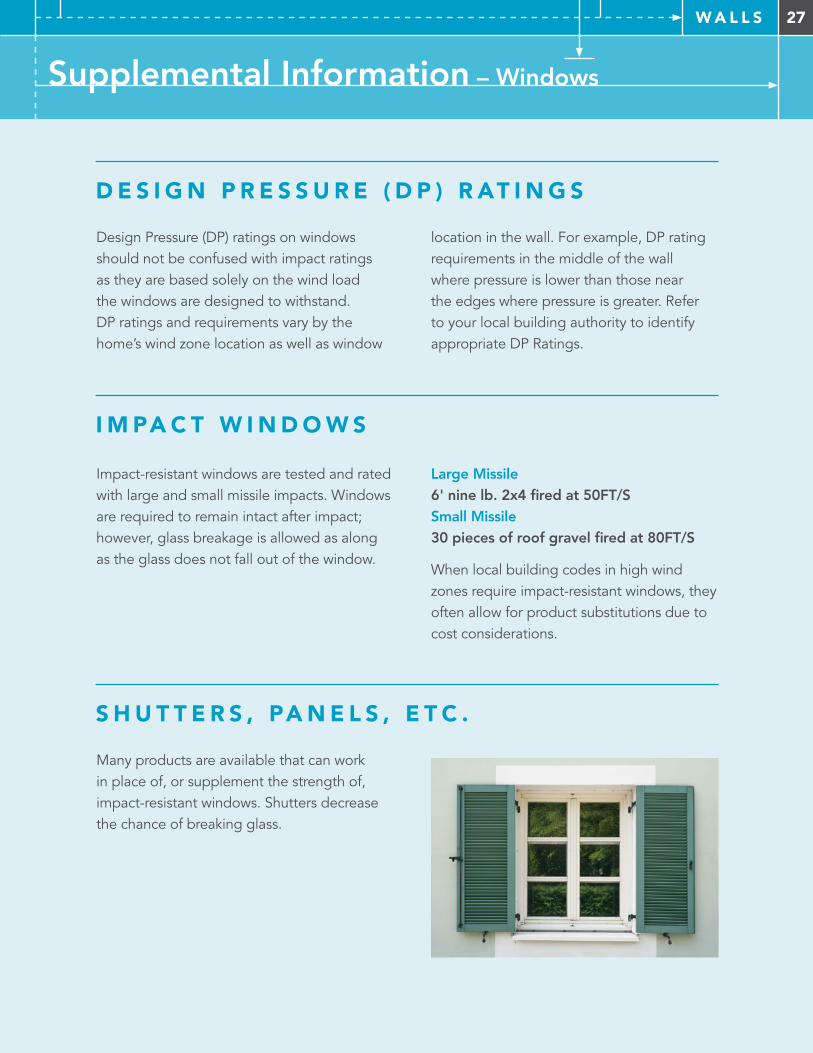
S H U T T E R S , PA N E L S , E T C .
Many products are available that can work in place of, or supplement the strength of, impact-resistant windows. Shutters decrease the chance of breaking glass.
28 W A L L S
Supplemental Information – Windows
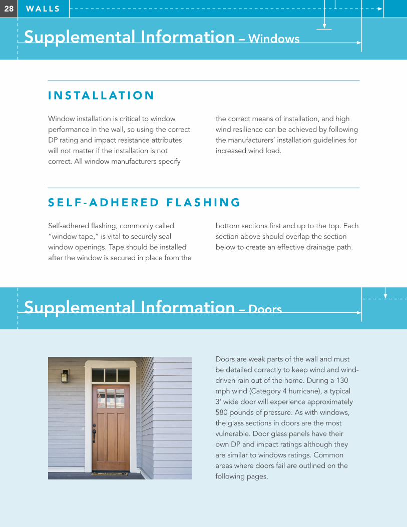
Doors are weak parts of the wall and must be detailed correctly to keep wind and wind-driven rain out of the home. During a 130 mph wind (Category 4 hurricane), a typical 3' wide door will experience approximately 580 pounds of pressure. As with windows, the glass sections in doors are the most vulnerable. Door glass panels have their own DP and impact ratings although they are similar to windows ratings. Common areas where doors fail are outlined on the following pages.
I N S TA L L AT I O N
Window installation is critical to window performance in the wall, so using the correct DP rating and impact resistance attributes will not matter if the installation is not correct. All window manufacturers specify
the correct means of installation, and high wind resilience can be achieved by following the manufacturers’ installation guidelines for increased wind load.
S E L F - A D H E R E D F L A S H I N G
Self-adhered flashing, commonly called “window tape,” is vital to securely seal window openings. Tape should be installed after the window is secured in place from the
bottom sections first and up to the top. Each section above should overlap the section below to create an effective drainage path.
Supplemental Information – Doors
29W A L L S
Supplemental Information – Doors
Hinges The hinge side of the door is also a major concern. Door hinges need specific attachments to the door frame and door to ensure proper connection.
Jamb and Frame to Wall If the door jamb and frame are not properly attached to the structure, the door system will fail. All door manufacturers provide detailed specifications on how to attach the system to the structure of the home.
D O O R T O J A M B A N D F R A M E
Latch A common weak point is the latch and lock because high winds can concentrate large forces on that single point. Many new door models have three and five point latching as opposed to the traditional single point at the latch and handle, which creates a stronger door to door frame connection.
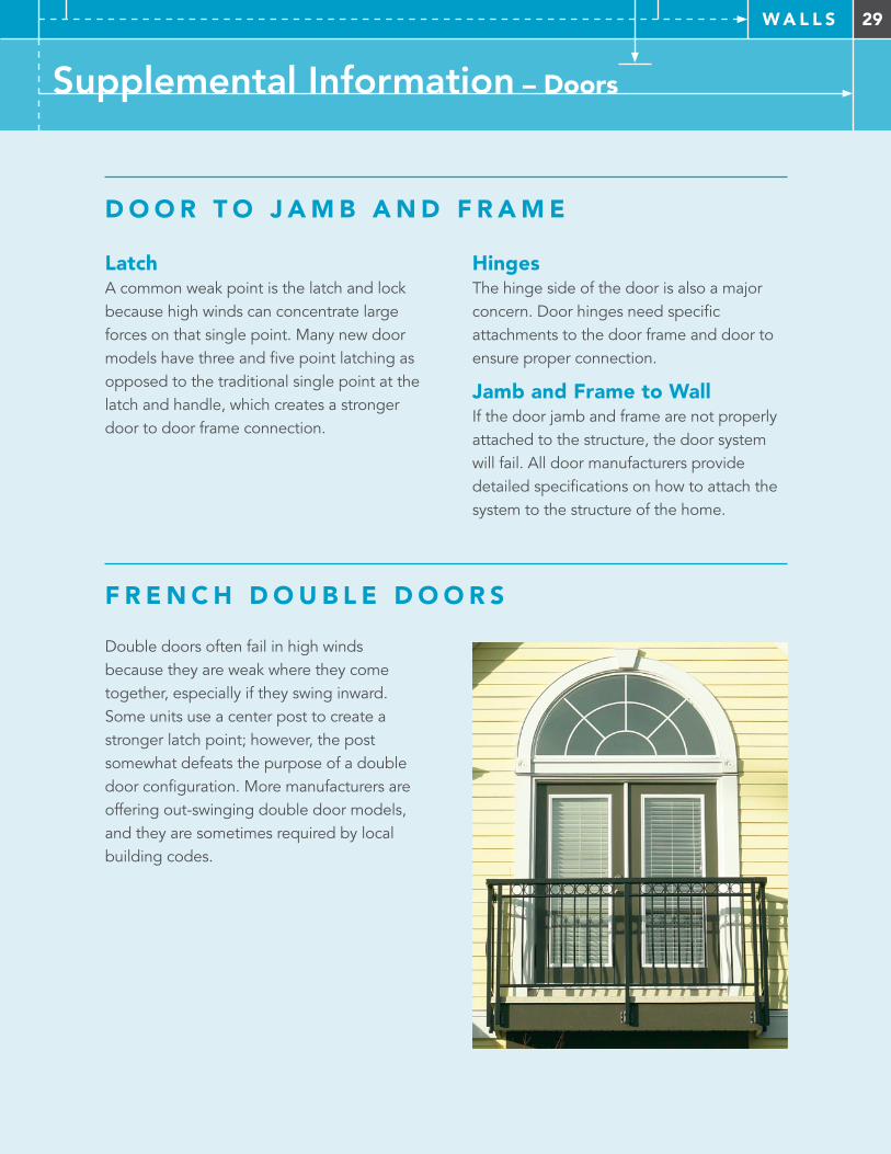
F R E N C H D O U B L E D O O R S
Double doors often fail in high winds because they are weak where they come together, especially if they swing inward. Some units use a center post to create a stronger latch point; however, the post somewhat defeats the purpose of a double door configuration. More manufacturers are offering out-swinging double door models, and they are sometimes required by local building codes.
30 W A L L S
Supplemental Information – Doors
G A R A G E D O O R S
W I N D - D R I V E N W AT E R
Like doors and windows, garage doors are a weak part of the wall, especially because most garages are designed to make the door opening as wide as possible. This wide opening requires a strong door frame that is commonly referred to as a “moment frame”. The wind load on a garage door is substantial. A typical 10'x10', single car garage door is subject to more than 6000 lbs. of pressure in 130 mph winds. Garage doors must be rated for pressures associated with the site design, wind speed, and exposure category. Garage doors are commonly made of thin sheet metal, fiberglass or similar materials so that they are lightweight for efficient lifting. As a result,
Seal Doors should be properly flashed and sealed for both wind and wind-driven water. All four sides of the door should seal tight to the frame, and all four sides of the frame should be sealed tight to the structure. A combination of flashing and sealers such as caulking, foam and silicone should be used.
they are vulnerable to damage by wind forces and windborne debris. Glass panels in garage doors are not recommended because they introduce additional weakness and glass panel, wind-rated garage doors are expensive options for typical residential construction. Roll up doors are often connected at only a few critical points. The concentrated loads on the edges must be accounted for when attaching garage doors. Anchoring into the wall is vital just as it is for windows and doors. Thresholds poured into the garage slab or installed onto the garage floor help keep out wind-driven water.
Thresholds The threshold is the bottom of the door frame and provides transition from outside to inside. Thresholds can be particularly vulnerable to wind-driven water. Sealing the bottom of the threshold to the door frame is important and is often overlooked at the time of installation.
31W A L L S
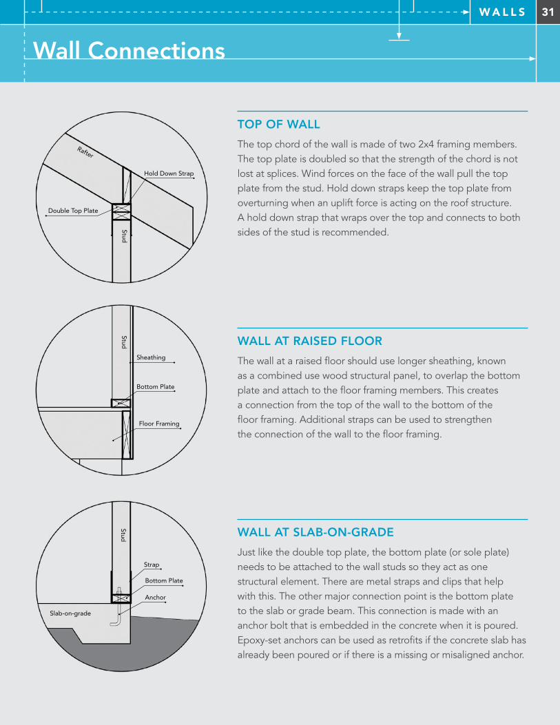
TOP OF WALL
The top chord of the wall is made of two 2x4 framing members. The top plate is doubled so that the strength of the chord is not lost at splices. Wind forces on the face of the wall pull the top plate from the stud. Hold down straps keep the top plate from overturning when an uplift force is acting on the roof structure. A hold down strap that wraps over the top and connects to both sides of the stud is recommended.
WALL AT RAISED FLOOR
The wall at a raised floor should use longer sheathing, known as a combined use wood structural panel, to overlap the bottom plate and attach to the floor framing members. This creates a connection from the top of the wall to the bottom of the floor framing. Additional straps can be used to strengthen the connection of the wall to the floor framing.
WALL AT SLAB-ON-GRADE
Just like the double top plate, the bottom plate (or sole plate) needs to be attached to the wall studs so they act as one structural element. There are metal straps and clips that help with this. The other major connection point is the bottom plate to the slab or grade beam. This connection is made with an anchor bolt that is embedded in the concrete when it is poured. Epoxy-set anchors can be used as retrofits if the concrete slab has already been poured or if there is a missing or misaligned anchor.
Hold Down Strap
Rafter
Double Top Plate
Stud
Stud
Bottom Plate
Anchor
Slab-on-grade
Strap
Floor Framing
Bottom Plate
Stud
Sheathing
Wall Connections
32 F O U N D AT I O N S
How Foundations Work in Wind
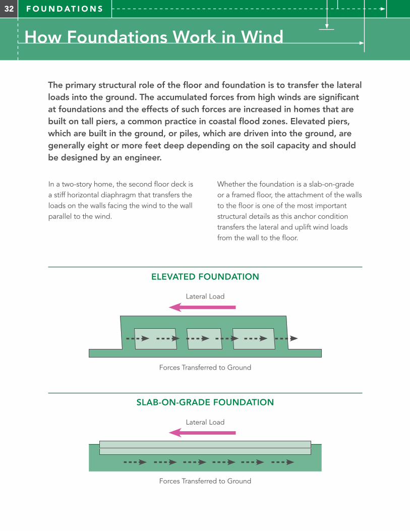
The primary structural role of the floor and foundation is to transfer the lateral loads into the ground. The accumulated forces from high winds are significant at foundations and the effects of such forces are increased in homes that are built on tall piers, a common practice in coastal flood zones. Elevated piers, which are built in the ground, or piles, which are driven into the ground, are generally eight or more feet deep depending on the soil capacity and should be designed by an engineer.
In a two-story home, the second floor deck is a stiff horizontal diaphragm that transfers the loads on the walls facing the wind to the wall parallel to the wind.
Whether the foundation is a slab-on-grade or a framed floor, the attachment of the walls to the floor is one of the most important structural details as this anchor condition transfers the lateral and uplift wind loads from the wall to the floor.
ELEVATED FOUNDATION
Forces Transferred to Ground
Lateral Load
SLAB-ON-GRADE FOUNDATION
Forces Transferred to Ground
Lateral Load
33F O U N D AT I O N S
Foundation Components
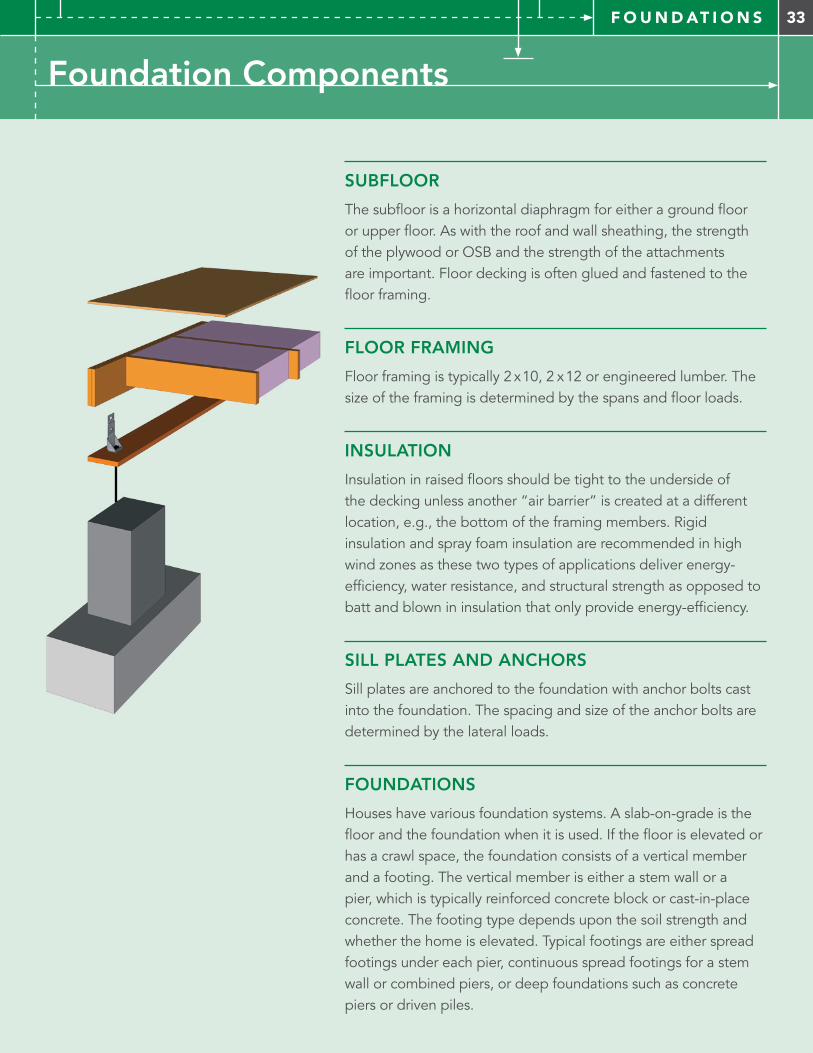
SUBFLOOR
The subfloor is a horizontal diaphragm for either a ground floor or upper floor. As with the roof and wall sheathing, the strength of the plywood or OSB and the strength of the attachments are important. Floor decking is often glued and fastened to the floor framing.
FLOOR FRAMING
Floor framing is typically 2 x10, 2 x12 or engineered lumber. The size of the framing is determined by the spans and floor loads.
INSULATION
Insulation in raised floors should be tight to the underside of the decking unless another “air barrier” is created at a different location, e.g., the bottom of the framing members. Rigid insulation and spray foam insulation are recommended in high wind zones as these two types of applications deliver energy-efficiency, water resistance, and structural strength as opposed to batt and blown in insulation that only provide energy-efficiency.
SILL PLATES AND ANCHORS
Sill plates are anchored to the foundation with anchor bolts cast into the foundation. The spacing and size of the anchor bolts are determined by the lateral loads.
FOUNDATIONS
Houses have various foundation systems. A slab-on-grade is the floor and the foundation when it is used. If the floor is elevated or has a crawl space, the foundation consists of a vertical member and a footing. The vertical member is either a stem wall or a pier, which is typically reinforced concrete block or cast-in-place concrete. The footing type depends upon the soil strength and whether the home is elevated. Typical footings are either spread footings under each pier, continuous spread footings for a stem wall or combined piers, or deep foundations such as concrete piers or driven piles.
34 F O U N D AT I O N S
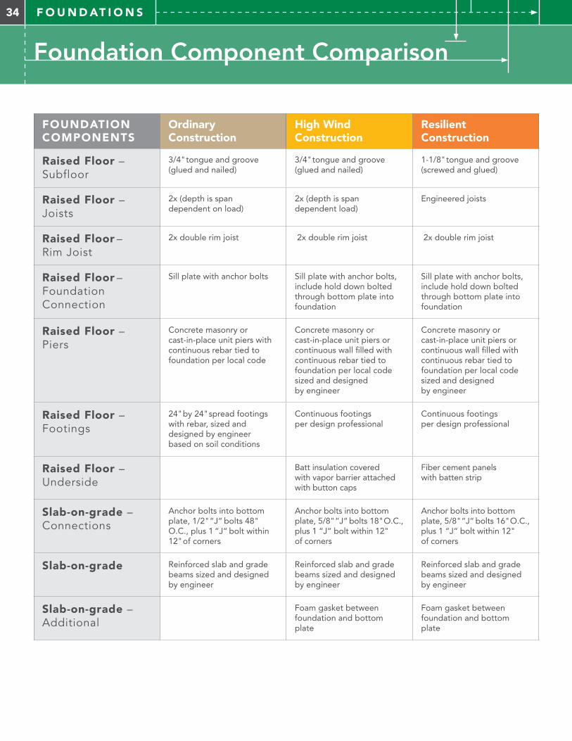
FOUNDATION COMPONENTS
Ordinary Construction
High Wind Construction
Resilient Construction
Raised Floor – Subfloor
3/4" tongue and groove (glued and nailed)
3/4" tongue and groove (glued and nailed)
1-1/8" tongue and groove (screwed and glued)
Raised Floor – Joists
2x (depth is span dependent on load)
2x (depth is span dependent load)
Engineered joists
Raised Floor – Rim Joist
2x double rim joist 2x double rim joist 2x double rim joist
Raised Floor – Foundation Connection
Sill plate with anchor bolts Sill plate with anchor bolts, include hold down bolted through bottom plate into foundation
Sill plate with anchor bolts, include hold down bolted through bottom plate into foundation
Raised Floor – Piers
Concrete masonry or cast-in-place unit piers with continuous rebar tied to foundation per local code
Concrete masonry or cast-in-place unit piers or continuous wall filled with continuous rebar tied to foundation per local code sized and designed by engineer
Concrete masonry or cast-in-place unit piers or continuous wall filled with continuous rebar tied to foundation per local code sized and designed by engineer
Raised Floor – Footings
24" by 24" spread footings with rebar, sized and designed by engineer based on soil conditions
Continuous footings per design professional
Continuous footings per design professional
Raised Floor – Underside
Batt insulation covered with vapor barrier attached with button caps
Fiber cement panels with batten strip
Slab-on-grade – Connections
Anchor bolts into bottom plate, 1/2" “J“ bolts 48" O.C., plus 1 “J“ bolt within 12" of corners
Anchor bolts into bottom plate, 5/8" “J“ bolts 18" O.C., plus 1 “J“ bolt within 12" of corners
Anchor bolts into bottom plate, 5/8" “J“ bolts 16" O.C., plus 1 “J“ bolt within 12" of corners
Slab-on-grade Reinforced slab and grade beams sized and designed by engineer
Reinforced slab and grade beams sized and designed by engineer
Reinforced slab and grade beams sized and designed by engineer
Slab-on-grade – Additional
Foam gasket between foundation and bottom plate
Foam gasket between foundation and bottom plate
Foundation Component Comparison
35F O U N D AT I O N S
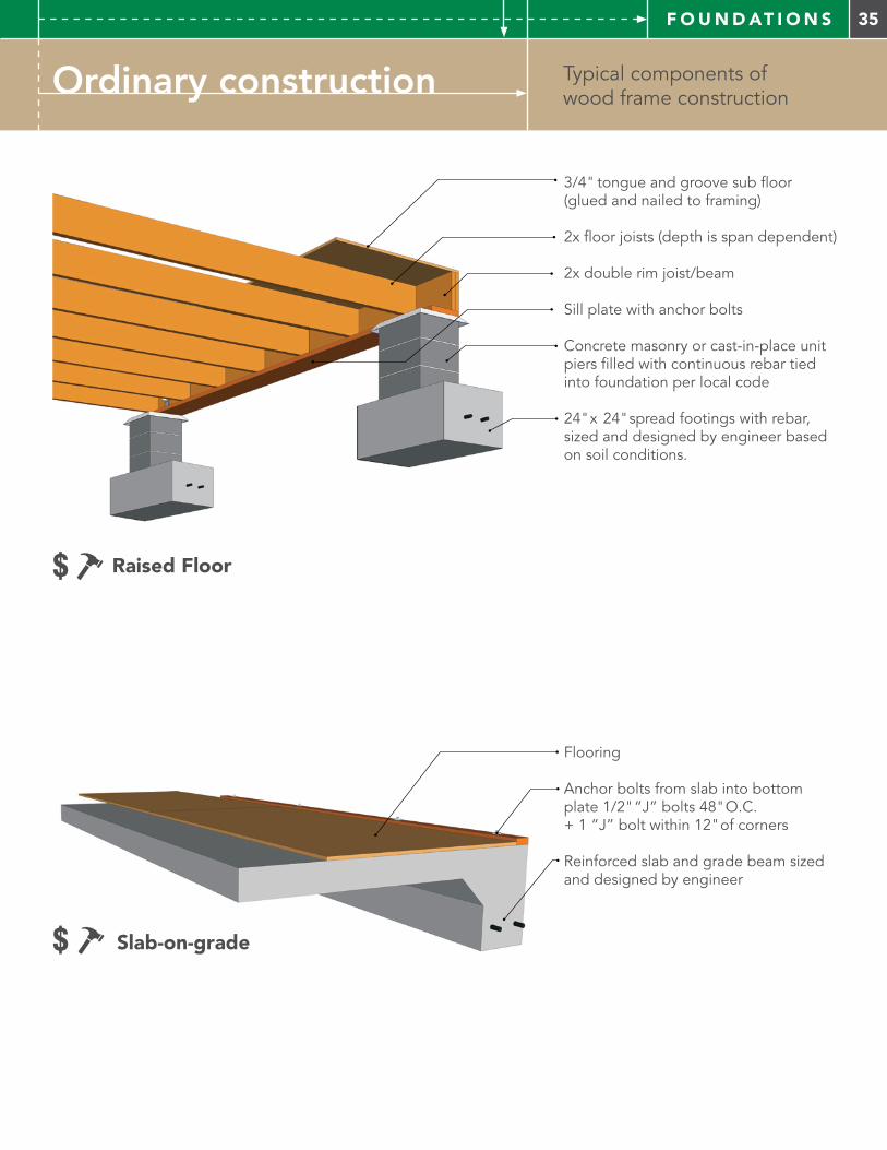
Typical components of wood frame constructionOrdinary construction
3/4" tongue and groove sub floor(glued and nailed to framing)
2x floor joists (depth is span dependent)
2x double rim joist/beam
Sill plate with anchor bolts
Concrete masonry or cast-in-place unit piers filled with continuous rebar tied into foundation per local code
24" x 24" spread footings with rebar, sized and designed by engineer based on soil conditions.
Flooring
Anchor bolts from slab into bottom plate 1/2" “J” bolts 48" O.C. + 1 “J” bolt within 12" of corners
Reinforced slab and grade beam sized and designed by engineer
$ Slab-on-grade
$ Raised Floor
36 F O U N D AT I O N S
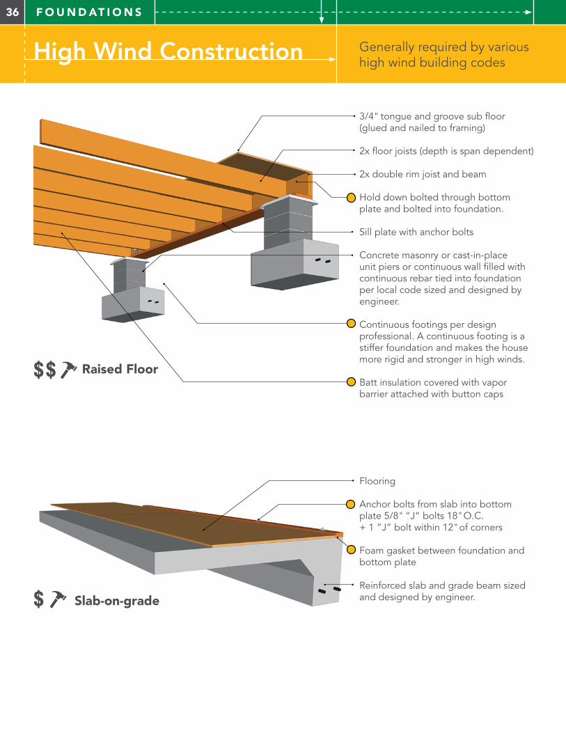
High Wind Construction Generally required by various high wind building codes
Flooring
Anchor bolts from slab into bottom plate 5/8" “J” bolts 18" O.C. + 1 “J” bolt within 12" of corners
Foam gasket between foundation and bottom plate
Reinforced slab and grade beam sized and designed by engineer.
3/4" tongue and groove sub floor (glued and nailed to framing)
2x floor joists (depth is span dependent)
2x double rim joist and beam
Hold down bolted through bottom plate and bolted into foundation.
Sill plate with anchor bolts
Concrete masonry or cast-in-place unit piers or continuous wall filled with continuous rebar tied into foundation per local code sized and designed by engineer.
Continuous footings per design professional. A continuous footing is a stiffer foundation and makes the house more rigid and stronger in high winds.
Batt insulation covered with vapor barrier attached with button caps
$ Slab-on-grade
$$ Raised Floor
37F O U N D AT I O N S
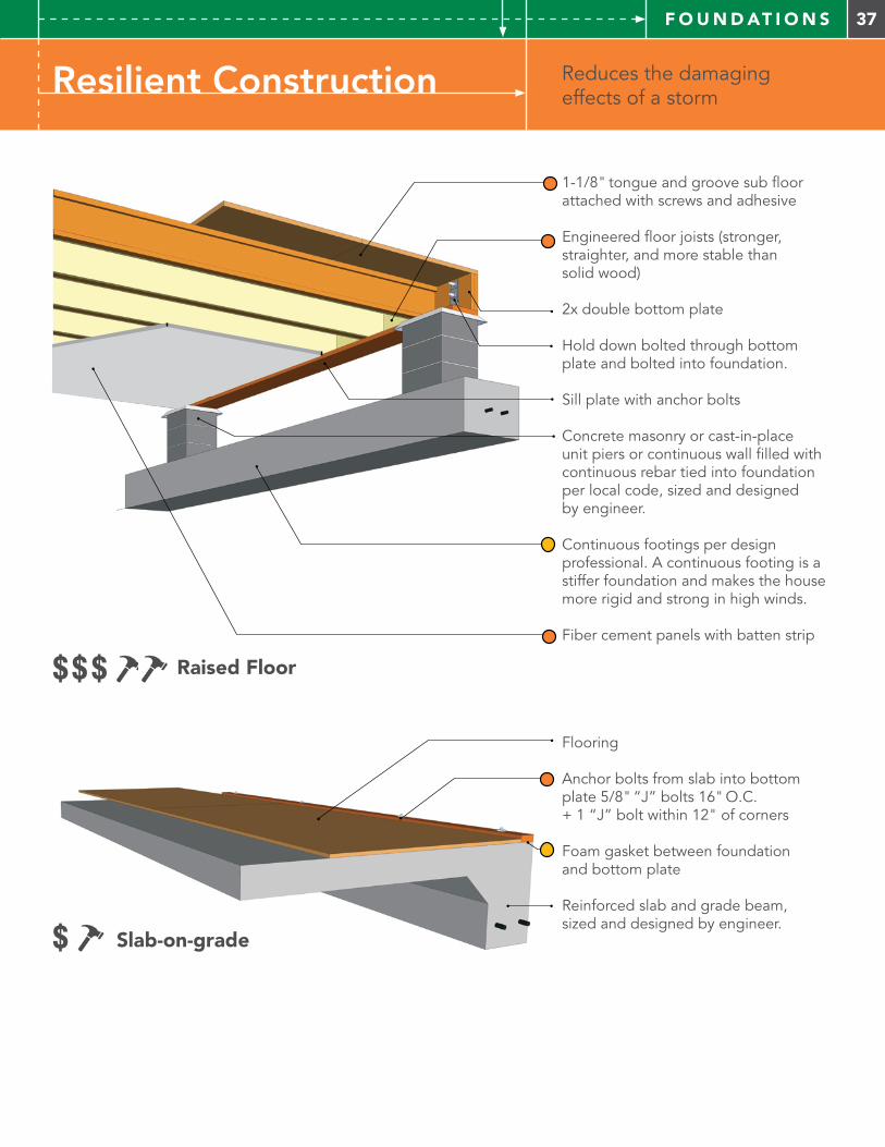
Resilient Construction Reduces the damaging effects of a storm
1-1/8" tongue and groove sub floor attached with screws and adhesive
Engineered floor joists (stronger, straighter, and more stable than solid wood)
2x double bottom plate
Hold down bolted through bottom plate and bolted into foundation.
Sill plate with anchor bolts
Concrete masonry or cast-in-place unit piers or continuous wall filled with continuous rebar tied into foundation per local code, sized and designed by engineer.
Continuous footings per design professional. A continuous footing is a stiffer foundation and makes the house more rigid and strong in high winds.
Fiber cement panels with batten strip
Flooring
Anchor bolts from slab into bottom plate 5/8" “J” bolts 16" O.C. + 1 “J” bolt within 12" of corners
Foam gasket between foundation and bottom plate
Reinforced slab and grade beam, sized and designed by engineer.
$$$ Raised Floor
$ Slab-on-grade
38 F O U N D AT I O N S
Supplemental Information – Floors & Foundations
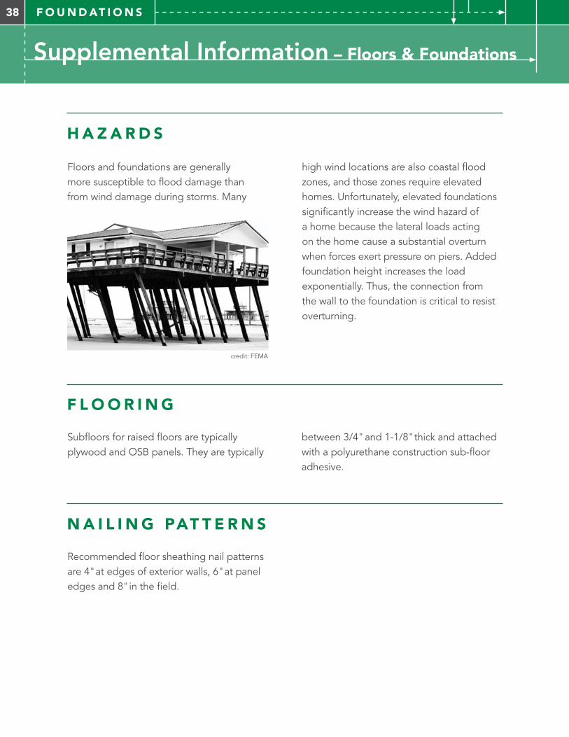
high wind locations are also coastal flood zones, and those zones require elevated homes. Unfortunately, elevated foundations significantly increase the wind hazard of a home because the lateral loads acting on the home cause a substantial overturn when forces exert pressure on piers. Added foundation height increases the load exponentially. Thus, the connection from the wall to the foundation is critical to resist overturning.
H A Z A R D S
N A I L I N G PAT T E R N S
Floors and foundations are generally more susceptible to flood damage than from wind damage during storms. Many
Recommended floor sheathing nail patterns are 4" at edges of exterior walls, 6" at panel edges and 8" in the field.
F L O O R I N G
Subfloors for raised floors are typically plywood and OSB panels. They are typically
between 3/4" and 1-1/8" thick and attached with a polyurethane construction sub-floor adhesive.
credit: FEMA
39F O U N D AT I O N S
Supplemental Information – Floors & Foundations
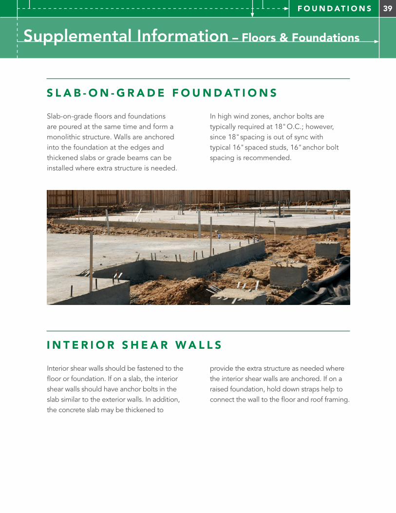
S L A B - O N - G R A D E F O U N D AT I O N S
Slab-on-grade floors and foundations are poured at the same time and form a monolithic structure. Walls are anchored into the foundation at the edges and thickened slabs or grade beams can be installed where extra structure is needed.
In high wind zones, anchor bolts are typically required at 18" O.C.; however, since 18" spacing is out of sync with typical 16" spaced studs, 16" anchor bolt spacing is recommended.
I N T E R I O R S H E A R W A L L S
Interior shear walls should be fastened to the floor or foundation. If on a slab, the interior shear walls should have anchor bolts in the slab similar to the exterior walls. In addition, the concrete slab may be thickened to
provide the extra structure as needed where the interior shear walls are anchored. If on a raised foundation, hold down straps help to connect the wall to the floor and roof framing.
40 S I T E
Resilient Landscape
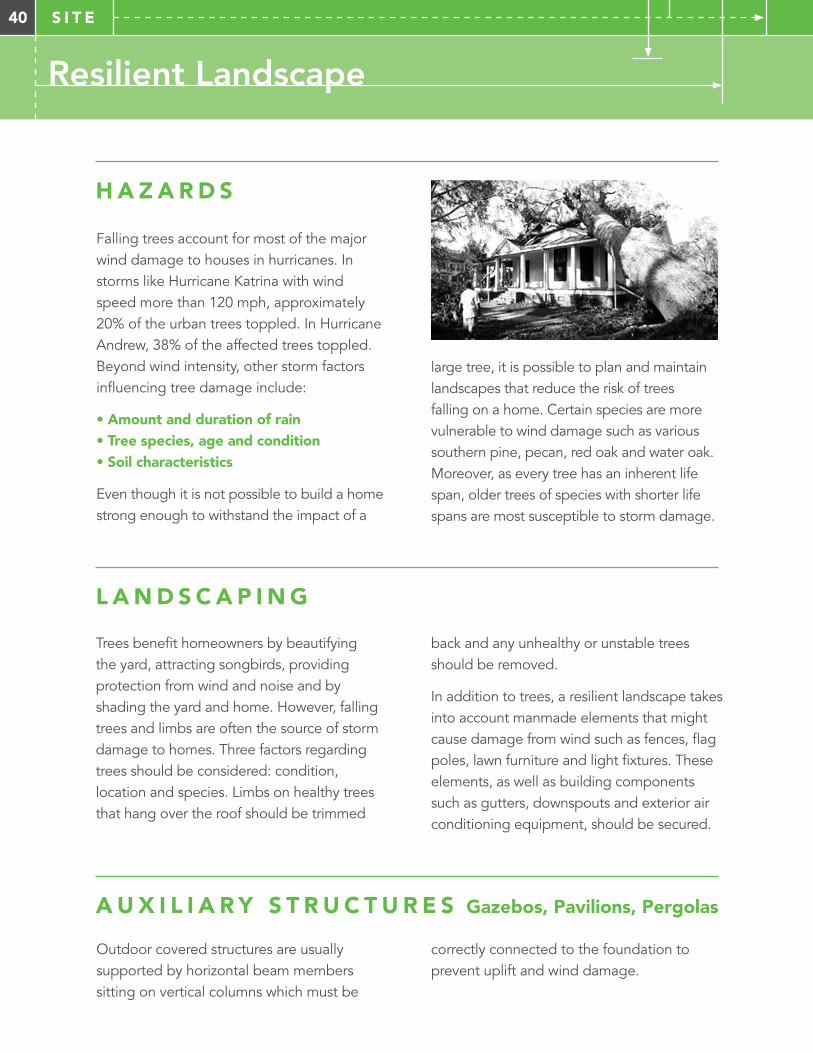
large tree, it is possible to plan and maintain landscapes that reduce the risk of trees falling on a home. Certain species are more vulnerable to wind damage such as various southern pine, pecan, red oak and water oak. Moreover, as every tree has an inherent life span, older trees of species with shorter life spans are most susceptible to storm damage.
H A Z A R D S
L A N D S C A P I N G
A U X I L I A R Y S T R U C T U R E S Gazebos, Pavilions, Pergolas
Falling trees account for most of the major wind damage to houses in hurricanes. In storms like Hurricane Katrina with wind speed more than 120 mph, approximately 20% of the urban trees toppled. In Hurricane Andrew, 38% of the affected trees toppled. Beyond wind intensity, other storm factors influencing tree damage include:
• Amount and duration of rain• Tree species, age and condition• Soil characteristics
Even though it is not possible to build a home strong enough to withstand the impact of a
Trees benefit homeowners by beautifying the yard, attracting songbirds, providing protection from wind and noise and by shading the yard and home. However, falling trees and limbs are often the source of storm damage to homes. Three factors regarding trees should be considered: condition, location and species. Limbs on healthy trees that hang over the roof should be trimmed
Outdoor covered structures are usually supported by horizontal beam members sitting on vertical columns which must be
back and any unhealthy or unstable trees should be removed.
In addition to trees, a resilient landscape takes into account manmade elements that might cause damage from wind such as fences, flag poles, lawn furniture and light fixtures. These elements, as well as building components such as gutters, downspouts and exterior air conditioning equipment, should be secured.
correctly connected to the foundation to prevent uplift and wind damage.
41S I T E
Resilient Landscape
R E S I L I E N T H O M E S Y S T E M S Standby Generators
The most common result of wind storms is loss of electrical power due to trees and limbs falling on power lines. Ideally, electrical services are run underground as this reduces risk of power outages; and communities benefit from these types of efforts to invest in more resilient power infrastructure. For the individual homeowner, loss of electrical power is not only inconvenient, but the lack of air conditioning allows mold growth inside the home. A resilient home is prepared for loss of power with good natural ventilation and a standby generator to provide power for a minimal amount of air conditioning and interior finishes that don’t support mold growth.
Loss of electrical power in a neighborhood can also affect the water and sewage system. Sewage check valves and back flow preventers can be used on homes to guard against contamination from systems that might not operate normally after a disaster.
Placement Details
Install the generator set:
• Outdoors • Near the incoming gas service • Near the main electrical panel(s)• On a flat, level mounting area
IMPORTANT PLACEMENT GUIDELINES
• The recommended distance from a structure is dependent on state and local codes.
• Locate the generator set so that the hot exhaust does not blow on plants or other combustible materials. No plants, shrubs, or other combustible materials are allowed within 1.2 m (4 ft.) of the exhaust end of the generator set.
• Do not install the generator set where exhaust gas could accumulate and seep inside or be drawn into a potentially occupied building. Furnace and other similar intakes must be at least 3 m (10 ft.) from the exhaust end of the generator set.
• Do not locate the generator set near patios, decks, play areas, or animal shelters.
• Do not install the composite mounting pad directly on grass, wood, or other combustible materials. Clear all combustible materials, including plants and shrubs, building materials, and lawn furniture, from an area at least 1.2 m (4 ft.) beyond the exhaust end of the generator.
• In flood hazard areas, locate the generator and its control systems above the highest expected flood level
• In high wind areas, the generator should be securely mounted to a concrete pad according to the mounting instructions in the installation manual.
42 A P P E N D I X
Additional Information & Resources
Walls
Roof
Spray Foam When applied to the underside of the roof deck, closed-cell spray polyurethane foam insulation has various characteristics to provide a sealed rood deck and secondary water barrier performance.
Properly applied spray foam can be considered as an impermeable insulation. Controlled air permeability helps to prevent and control bulk water entry which
Connectors and Straps For information how to choose metal connectors and fasteners, visit: www.strongtie.com
Alternate Construction Methods This guide focuses on standard wood frame construction methods. For more information about alternative construction methods such as masonry, steel frame, factory-assembled or panelized construction systems, visit:
create a sealed roof deck. Spray foam can also be considered a water/secondary resistive barrier and provides support against wind uplift and racking.
For resilient construction consider applying a 3" minimum full insulating layer between roof rafters/trusses.
For more information and product resources please visit: www.flash.org/basf/rdghouse.pdf
LTH Steel Structures www.lthsteelstructures.com/ building-types/steel-framing-kits- custom-homes
National Association of Home Builders www.nahb.org
Manufacturers Home Institute www.manufacturedhousing.org
Structural Insulated Panel Association www.sips.org
Metal Roofing Options For further information on the different types of metal roofing systems visit:
www.facilitiesnet.com/roofing/article/Metal-Roofs-Compare-the-Different-Systems--9806#
www.unioncorrugating.com/all_products.html
www.metalroofing.com/v2/content/metal-roofing/index.cfm?
www.metalroofing.com/v2/content/guide/types/
Residential Advantage Building Systems www.resadvan.com
Insulating Concrete Form Association (ICFA) www.forms.org
National Concrete Masonry Association (NCMA) www.ncma.org
Precast/Prestressed Concrete Institute (PCI) www.pci.org
43A P P E N D I X
Additional Information & Resources
Floors and Foundation
Site
References
Engineered Floor Framing Systems For more information about engineered floor framing systems visit: www.buildgp.com/engineered-lumber
Auxiliary StructuresThese covered structures are usually supported by horizontal beam members sitting on vertical columns, which must be correctly connected to the foundation to prevent uplift and wind damage.
Home Builders Guide to Coastal Construction Technical Fact Sheet Series FEMA P-499 / December 2012 www.fema.gov/media-library/assets/documents/6131
Concrete and Rebar For further information about concrete construction and to find out more about alternative construction methods using concrete please visit:
Standby Power GenerationFor more information visit: www.kohlergenerators.com
Hurricane Katrina in the Gulf Coast: Building Performance Observations, Recommendations, and Technical Guidance Mitigation Assessment Team Report FEMA 549 / July 2006 www.fema.gov/media-library/assets/documents/4069
Portland Cement Association (PCA) www.cement.org
Concrete Reinforcing Steel Institute www.crsi.org
44 A C K N O W L E D G E M E N T S
Thank You
We would like to thank and recognize the following individuals and their respective organizations for their donation of expertise, time and commitment to the creation and publication of the
Resilient Design Guide. Their generosity and passion for making America a more disaster-resilient nation are evident in their unconditional support for this project.
Charrette Participants
Charrette Review Committee
Resilient Design Guide Reviewers
Illya Azaroff, AIAPLUS LAB architects + experimentation
Greg Beste, AIAHalliwell Engineering Associates
Lance Jay Brown, FAIACenter for Architecture
Nathan Butler, AIA HKS
Brandon Dake, AIADake Wells Architecture
Kathleen Dorgan, AIADorgan Architecture and Planning
Thomas AllenReedy Creek Improvement District
Roy EdenCity of Orlando
Illya Azaroff, AIA PLUS LAB architects + experimentation
Lance Jay Brown, FAIACenter for Architecture
Leslie Chapman-Henderson (Copy Editor)Federal Alliance for Safe Homes (FLASH)
Jeff FeidState Farm Insurance Companies
Rose Geier Grant, AIA State Farm Insurance Companies
Sarah Grider, Assoc. AIAGulf Coast Community Design Studio
Mike GroteGulf Coast Community Design Studio
Barbara HarrisonFederal Alliance for Safe Homes (FLASH)
Mike Rimoldi, MPA, CBO, CFM, CBC Hillsborough County, FL
Ismael Rodriquez The Home Depot
Jeff FeidState Farm Insurance Companies
Audrey GaloArchitecture for Humanity
Rose Geier Grant, AIA State Farm Insurance Companies
Russ GriffithHabitat for Humanity
Michael Lingerfelt, FAIALingerfelt International
Bruce McCullenMcCullen Consulting
Rachel Minnery, AIA Architecture for Humanity
Brian OmanBASF
Freddy PaigeClemson University
David Perkes, AIAGulf Coast Community Design Studio
Daniel SmithUniversity of Florida
Mike WelchHabitat for Humanity
Michael Lingerfelt, FAIALingerfelt International
Bruce McCullenMcCullen Consulting
Rachel Minnery, AIA Architecture for Humanity
Brian OmanBASF
Jeff Seabold, AIASeabold Architectural Studio
Randy Shackelford, PESimpson Strong-Tie Co.
Tim SmailFederal Alliance for Safe Homes (FLASH)
Donn Thompson, AIAPortland Cement Association
Melanie TydrichKohler Co.
Emily Van Court, Assoc. AIA Center for Building Excellence
Cletus YoderMennonite Disaster Services
Dr. David O. PrevattUniversity of Florida
Randy Shackelford, PESimpson Strong-Tie Co.
Donn Thompson, AIAPortland Cement Association
Melanie TydrichKohler Co.

Notes
FEDERAL ALLIANCE FOR SAFE HOMES, INC.1427 Piedmont Drive, Suite 2Tallahassee, Florida 32308877. 221.SAFE (7233)
www.flash.org
@federalalliance
federalalliance