Embed Size (px)
Citation preview

© 2007 Cisco Systems, Inc. All rights reserved. Cisco ConfidentialPresentation_ID 1
ResilientCampus NetworkDesign

© 2007 Cisco Systems, Inc. All rights reserved. Cisco ConfidentialPresentation_ID 2
Next Generation Campus Networks
� Campus network design is evolving in response to multiple drivers
User Expectations: Always ON Access to communications
Business Requirements: Globalization means true 24x365
Technology Requirements: Unified Communications, high definition interactive video, new traffic patterns
Work Environment Requirements: Anytime anywhere access
Unexpected Requirements: Worms, viruses, …
� Campus design needs to evolve to support the evolving business and technology drivers
Evolving Design Requirements
SiSi SiSi SiSi SiSi
SiSi SiSi
SiSi SiSi

© 2007 Cisco Systems, Inc. All rights reserved. Cisco ConfidentialPresentation_ID 3
Resilient Campus Network DesignAgenda
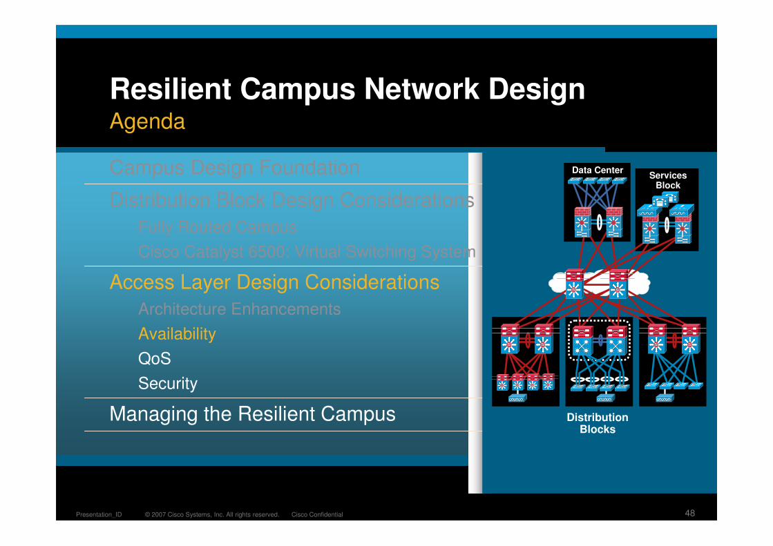
Campus Design Foundation
Distribution Block Design Considerations
Fully Routed Campus
Cisco Catalyst 6500: Virtual Switching System
Access Layer Design Considerations
Architecture Enhancements
Availability
QoS
Security
Managing the Resilient Campus Distribution Blocks
SiSiSiSi
SiSiSiSi
SiSi
Data Center
SiSi SiSi
ServicesBlock
SiSi SiSi SiSi

© 2007 Cisco Systems, Inc. All rights reserved. Cisco ConfidentialPresentation_ID 4
High Availability Campus Design
� Optimize the interaction of the physical redundancy with the network protocols
Provide the necessary amount of redundancy
Pick the right protocol for the requirement
Optimize the tuning of the protocol
� The network looks like this so that we can map the protocols onto the physical topology
� We want to build networks that look like this
WANData Center
Services Block
Distribution Blocks
Layer 2 or Layer 3
RedundantSwitches
Layer 3 Equal Cost Links
Structure, Modularity and Hierarchy
SiSiSiSi
SiSiSiSiSiSiSiSi
RedundantLinks
RedundantSupervisor
SiSiSiSiSiSiSiSi
© 2007 Cisco Systems, Inc. All rights reserved. Cisco ConfidentialPresentation_ID 5
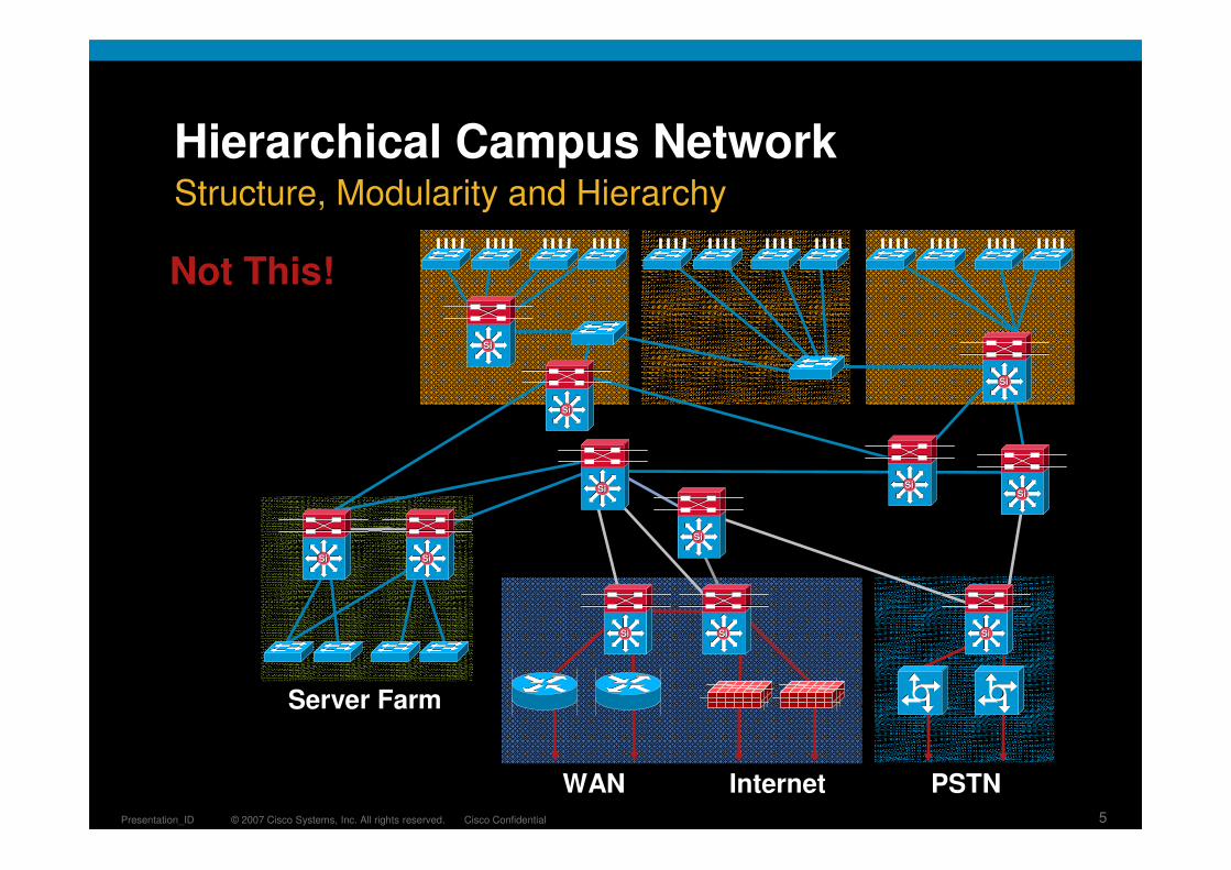
Hierarchical Campus Network
Server Farm
WAN Internet PSTN
Not This!
Structure, Modularity and Hierarchy
SiSi
SiSi
SiSiSiSi
SiSi
SiSi
SiSi
SiSiSiSi SiSi
SiSiSiSi

© 2007 Cisco Systems, Inc. All rights reserved. Cisco ConfidentialPresentation_ID 6
Redundancy and Protocol Interaction
� Direct point-to-point fiber provides for fast failure detection
� IEEE 802.3z and 802.3ae link negotiation define the use of Remote Fault Indicator and Link Fault Signaling mechanisms
� Bit D13 in the Fast Link Pulse (FLP) can be set to indicate a physical fault to the remote side
� Do not disable auto-negotiation on GigE and 10GigE interfaces
� Carrier-Delay
3560, 3750 and 4500—0 msec
6500—Leave it at default 50 msec
� The default debounce timer on GigE and 10GigE fiber linecards is 10 msec
� The minimum debounce for copper is 300 msec
1
2
3
Linecard Throttling: Debounce Timer
Remote IEEE Fault Detection Mechanism
Cisco IOS Throttling: Carrier Delay Timer
1
Link Redundancy and Failure Detection
SiSiSiSi

© 2007 Cisco Systems, Inc. All rights reserved. Cisco ConfidentialPresentation_ID 7
Redundancy and Protocol Interaction
� In the recommended distribution block design recovery of access to distribution link failures is accomplished based on L2 CAM updates not spanning tree
� No dependence on external events (no need to wait for spanning tree convergence)
� Behavior is deterministic
TCN
All Links Forwarding: In an Environment with All Links Active Traffic Is Restored Based on HW Recovery
� Indirect link failures are harder to detect
� With no direct HW notification of link loss or topology change convergence times are dependent on SW notification
� In certain topologies the need for TCN updates or dummy multicast flooding (uplink fast) is necessary for convergence
Link Neighbor Failure Detection
SiSiSiSi
© 2007 Cisco Systems, Inc. All rights reserved. Cisco ConfidentialPresentation_ID 8
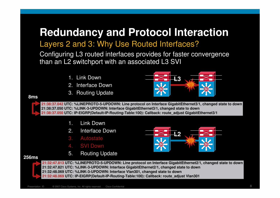
Redundancy and Protocol Interaction
Configuring L3 routed interfaces provides for faster convergencethan an L2 switchport with an associated L3 SVI
21:32:47.813 UTC: %LINEPROTO-5-UPDOWN: Line protocol on Interface GigabitEthernet2/1, changed state to down21:32:47.821 UTC: %LINK-3-UPDOWN: Interface GigabitEthernet2/1, changed state to down
21:32:48.069 UTC: %LINK-3-UPDOWN: Interface Vlan301, changed state to down21:32:48.069 UTC: IP-EIGRP(Default-IP-Routing-Table:100): Callback: route_adjust Vlan301
1. Link Down
2. Interface Down
3. Autostate
4. SVI Down
5. Routing Update
21:38:37.042 UTC: %LINEPROTO-5-UPDOWN: Line protocol on Interface GigabitEthernet3/1, changed state to down21:38:37.050 UTC: %LINK-3-UPDOWN: Interface GigabitEthernet3/1, changed state to down
21:38:37.050 UTC: IP-EIGRP(Default-IP-Routing-Table:100): Callback: route_adjust GigabitEthernet3/1
L2
L31. Link Down
2. Interface Down
3. Routing Update8ms
256ms
Layers 2 and 3: Why Use Routed Interfaces?
SiSiSiSi
SiSiSiSi
© 2007 Cisco Systems, Inc. All rights reserved. Cisco ConfidentialPresentation_ID 9
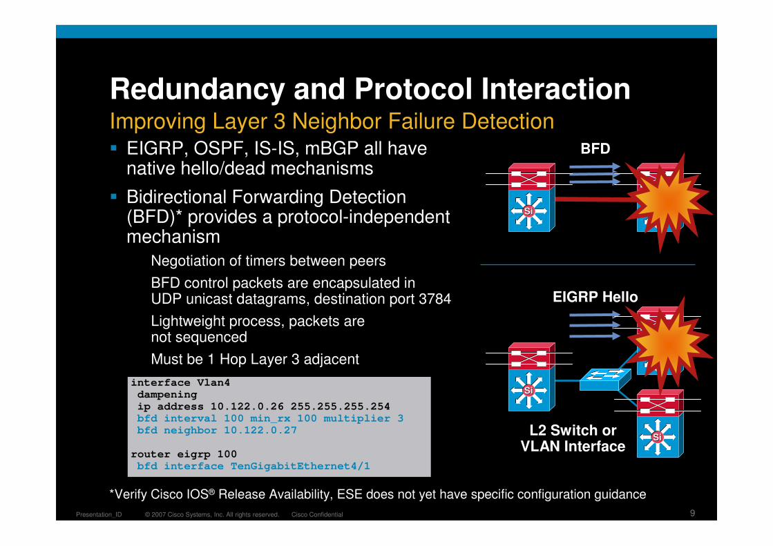
Redundancy and Protocol Interaction
� EIGRP, OSPF, IS-IS, mBGP all have native hello/dead mechanisms
� Bidirectional Forwarding Detection (BFD)* provides a protocol-independent mechanism
Negotiation of timers between peers
BFD control packets are encapsulated in UDP unicast datagrams, destination port 3784
Lightweight process, packets are not sequenced
Must be 1 Hop Layer 3 adjacent
EIGRP Hello
interface Vlan4dampeningip address 10.122.0.26 255.255.255.254bfd interval 100 min_rx 100 multiplier 3bfd neighbor 10.122.0.27
router eigrp 100bfd interface TenGigabitEthernet4/1
L2 Switch orVLAN Interface
Improving Layer 3 Neighbor Failure DetectionBFD
SiSi
SiSi
SiSi
SiSi
SiSi
*Verify Cisco IOS® Release Availability, ESE does not yet have specific configuration guidance
© 2007 Cisco Systems, Inc. All rights reserved. Cisco ConfidentialPresentation_ID 10
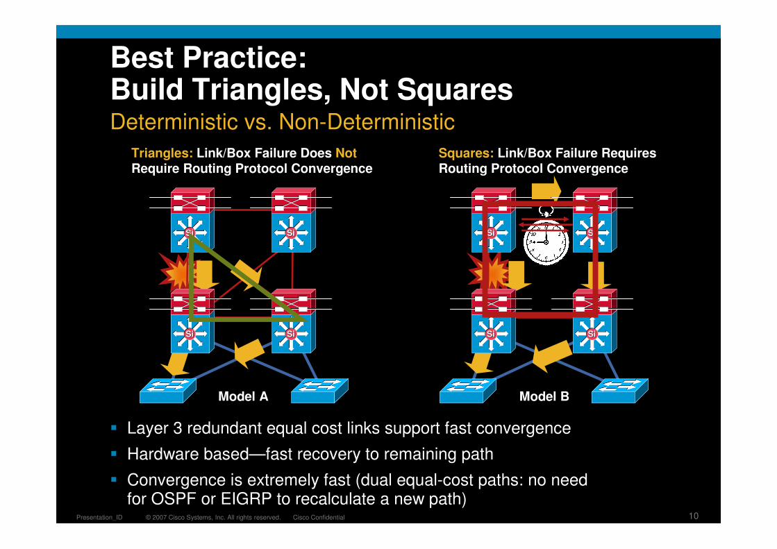
Best Practice: Build Triangles, Not Squares
� Layer 3 redundant equal cost links support fast convergence
� Hardware based—fast recovery to remaining path
� Convergence is extremely fast (dual equal-cost paths: no need for OSPF or EIGRP to recalculate a new path)
Triangles: Link/Box Failure Does NotRequire Routing Protocol Convergence
Model A
Squares: Link/Box Failure Requires Routing Protocol Convergence
Model B
Deterministic vs. Non-Deterministic
SiSiSiSi
SiSiSiSi
SiSiSiSi
SiSiSiSi

© 2007 Cisco Systems, Inc. All rights reserved. Cisco ConfidentialPresentation_ID 11
Cisco Catalyst Switch
Equal Cost Multi-Path Convergence
Link failure detection
Software Routing Table (RIB)
Prefix Next Hop Interface
10.255.0.0/16 10.10.1.1 gig 1/1
10.20.1.1 gig 1/2
Cisco IOS SoftwareCEF Tables
FIB Table
Prefix Adjacency Ptr
10.255.0.0/16 Adj1 (gig 1/1)
Adj2 (gig 1/2)
Adjacency Table
Rewrite Information
AA.AA.AA.AA.AA, VLAN
BB.BB.BB.BB.BB, VLAN
Hardware Tables
FIB Table
Prefix Adjacency Ptr
10.255.0.0/16 Adj1 (gig 1/1)
Adj2 (gig 1/2)
Adjacency Table
Rewrite Information
AA.AA.AA.AA.AA, VLAN
BB.BB.BB.BB.BB, VLAN
Removal of the entries in the routing table
Update of the software CEF table to reflect to loss of the next hop adjacencies
Update of the hardware tables
1
Remote Link Failure Detection
2
3
4
1
2
3
4
Routing Protocol Process
5Routing protocol notification and reconvergence
5
Time to Recovery CEF Paths
SiSi
SiSi
SiSi

© 2007 Cisco Systems, Inc. All rights reserved. Cisco ConfidentialPresentation_ID 12
Resilient Campus Network DesignAgenda
Campus Design Foundation
Distribution Block Design Considerations
Fully Routed Campus
Cisco Catalyst 6500: Virtual Switching System
Access Layer Design Considerations
Architecture Enhancements
Availability
QoS
Security
Managing the Resilient Campus Distribution Blocks
SiSiSiSi
SiSiSiSi
SiSi
Data Center
SiSi SiSi
ServicesBlock
SiSi SiSi SiSi

© 2007 Cisco Systems, Inc. All rights reserved. Cisco ConfidentialPresentation_ID 13
Distribution Layer
� Availability, load balancing, QoS and provisioning are the important considerations at this layer
� Aggregates wiring closets (access layer) and uplinks to core
� Protects core from high density peering and bounds Spanning Tree
� Route summarization, fast convergence, redundant path load sharing
� HSRP or GLBP to provide first hop redundancy
SiSiSiSi
SiSiSiSi
Policy, Convergence, QoS, and High Availability

© 2007 Cisco Systems, Inc. All rights reserved. Cisco ConfidentialPresentation_ID 14
Multilayer Network Design
� Each access switch has unique VLANs
� No Layer 2 loops
� Layer 3 link between distribution
� No blocked links
� At least some VLANs span multiple access switches
� Layer 2 loops
� Layers 2 and 3 running over link between distribution
� Blocked links
Vlan 10 Vlan 20 Vlan 30 Vlan 30 Vlan 30 Vlan 30
Layer 2 Access with Layer 3 Distribution
SiSiSiSiSiSiSiSi

© 2007 Cisco Systems, Inc. All rights reserved. Cisco ConfidentialPresentation_ID 15
Multilayer Network Design
� Implement physical L2 loops only when you have to
� Spanning tree protocol is very, very rarely the problem
� L2 has no native mechanism to dampen down a problem
� Utilize Rapid PVST+ for best convergence
� Limit the size of the L2 domain
� Complex L2 topologies take longer to converge
� Clear unnecessary VLANs from trunk configuration
Layer 2 Loops and Spanning Tree
3/2 3/2
3/1 3/1
Switch 1 Switch 2
DST MAC 0000.0000.4444
DST MAC 0000.0000.4444
0000.0000.3333

© 2007 Cisco Systems, Inc. All rights reserved. Cisco ConfidentialPresentation_ID 16
Layer 2 Loops and Spanning Tree
� The root bridge should stay where you put it
Loopguard and rootguard
UDLD
� Only end station traffic should be seen on an edge port
BPDU guard
Port-Security
� There is a reasonable limitto B-Cast and M-Cast traffic volumes
Configure storm control onbackup links to aggressivelyrate limit B-Cast and M-Cast
Utilize Sup720 rate limiters or SupIV/V with HW queuing structure
BPDU Guard or RootguardPortFast
Port Security
Rootguard
Loopguard
STP Root
Loopguard
Storm Control
Spanning Tree Should Behave the Way You Expect
SiSiSiSi
© 2007 Cisco Systems, Inc. All rights reserved. Cisco ConfidentialPresentation_ID 17
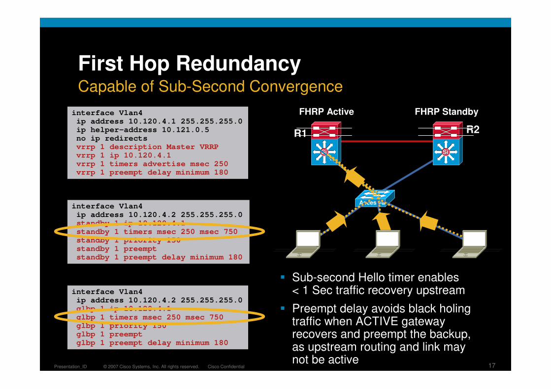
First Hop Redundancy
� Sub-second Hello timer enables < 1 Sec traffic recovery upstream
� Preempt delay avoids black holing traffic when ACTIVE gateway recovers and preempt the backup, as upstream routing and link may not be active
interface Vlan4ip address 10.120.4.2 255.255.255.0standby 1 ip 10.120.4.1standby 1 timers msec 250 msec 750standby 1 priority 150standby 1 preemptstandby 1 preempt delay minimum 180
interface Vlan4ip address 10.120.4.2 255.255.255.0glbp 1 ip 10.120.4.1glbp 1 timers msec 250 msec 750glbp 1 priority 150glbp 1 preemptglbp 1 preempt delay minimum 180
interface Vlan4ip address 10.120.4.1 255.255.255.0ip helper-address 10.121.0.5no ip redirectsvrrp 1 description Master VRRPvrrp 1 ip 10.120.4.1vrrp 1 timers advertise msec 250vrrp 1 preempt delay minimum 180
HSRP Config
GLBP Config
VRRP ConfigCapable of Sub-Second Convergence
SiSi
FHRP Active FHRP Standby
Access-a
R1 R2
SiSi

© 2007 Cisco Systems, Inc. All rights reserved. Cisco ConfidentialPresentation_ID 18
First Hop Redundancy with Load Balancing
� Each member of a GLBP redundancy group owns a unique virtual MAC address for a common IP address/default gateway
� When end stations ARP for the common IP address/default gateway they are given a load balanced virtual MAC address
� Host A and host B send traffic to different GLBP peers but have the same default gateway
10.88.1.0/24
.5.4
.1 .2
vIP10.88.1.10
GLBP 1 ip 10.88.1.10vMAC 0000.0000.0001
GLBP 1 ip 10.88.1.10vMAC 0000.0000.0002
ARPs for 10.88.1.10Gets MAC 0000.0000.0001
ARPs for 10.88.1.10Gets MAC 0000.0000.0002
R1 R2ARP
Reply
Cisco Gateway Load Balancing Protocol (GLBP)
Note: GLBP supported on Cisco Catalyst® 6500(Sup720) and 4500(Sup6E)
© 2007 Cisco Systems, Inc. All rights reserved. Cisco ConfidentialPresentation_ID 19
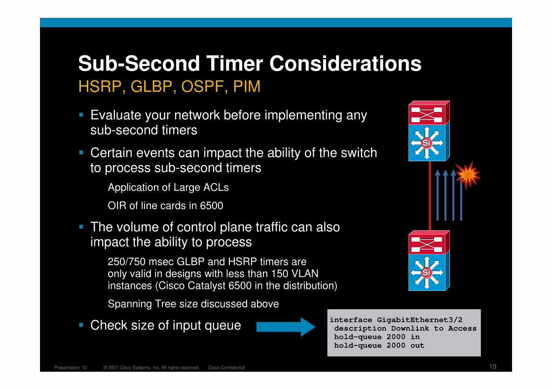
Sub-Second Timer Considerations
� Evaluate your network before implementing any sub-second timers
� Certain events can impact the ability of the switch to process sub-second timers
Application of Large ACLs
OIR of line cards in 6500
� The volume of control plane traffic can also impact the ability to process
250/750 msec GLBP and HSRP timers are only valid in designs with less than 150 VLAN instances (Cisco Catalyst 6500 in the distribution)
Spanning Tree size discussed above
� Check size of input queueinterface GigabitEthernet3/2description Downlink to Accesshold-queue 2000 inhold-queue 2000 out
HSRP, GLBP, OSPF, PIM
SiSi
SiSi

© 2007 Cisco Systems, Inc. All rights reserved. Cisco ConfidentialPresentation_ID 20
Multilayer Network Design
� Match Cisco CatOS/Cisco IOS EtherChannel®
settings and tune load balancing
� Summarize routes towards core
� Limit redundant IGP peering
� STP Root and HSRP primary or GLBP and STP port cost tuning to load balance on uplinks
� Set trunk mode on/nonegotiate
� Disable EtherChannel unless needed
� RootGuard on downlinks
� LoopGuard on uplinks
� Set port host on access layer ports:Disable trunking
Disable EtherChannel
Enable PortFast
� RootGuard or BPDU-Guard
Vlan 30 Vlan 30 Vlan 30
SiSiSiSi
SiSiSiSi
Well Understood Best Practices

© 2007 Cisco Systems, Inc. All rights reserved. Cisco ConfidentialPresentation_ID 21
Resilient Campus Network DesignAgenda
Campus Design Foundation
Distribution Block Design Considerations
Fully Routed Campus
Cisco Catalyst 6500: Virtual Switching System
Access Layer Design Considerations
Architecture Enhancements
Availability
QoS
Security
Managing the Resilient Campus Distribution Blocks
SiSiSiSi
SiSiSiSi
SiSi
Data Center
SiSi SiSi
ServicesBlock
SiSi SiSi SiSi

© 2007 Cisco Systems, Inc. All rights reserved. Cisco ConfidentialPresentation_ID 22
Routing to the Edge
� Move the Layer 2/3 demarcation to the network edge
� Upstream convergence times triggered by hardware detection of light lost from upstream neighbor
10.1.20.0
10.1.120.0
VLAN 20 Data
VLAN 120 Voice
VLAN 40 Data
VLAN 140 Voice
10.1.40.0
10.1.140.0
EIGRP/OSPF EIGRP/OSPF
GLBP Model
Layer 3
Layer 2
Layer 3
Layer 2EIGRP/OSPF EIGRP/OSPF
Layer 3 Distribution with Layer 3 Access
SiSiSiSi
© 2007 Cisco Systems, Inc. All rights reserved. Cisco ConfidentialPresentation_ID 23
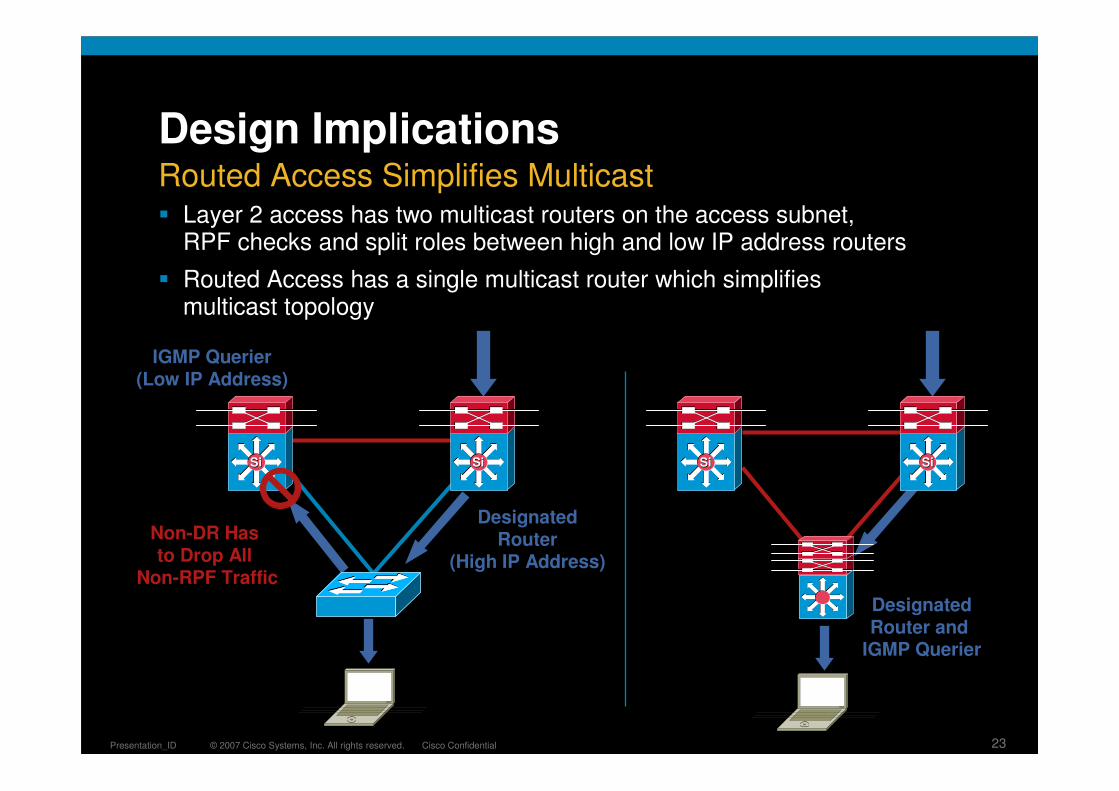
DesignatedRouter
(High IP Address)
IGMP Querier(Low IP Address)
DesignatedRouter and
IGMP Querier
Non-DR Has to Drop All
Non-RPF Traffic
Routed Access Simplifies Multicast
Design Implications
� Layer 2 access has two multicast routers on the access subnet, RPF checks and split roles between high and low IP address routers
� Routed Access has a single multicast router which simplifies multicast topology
SiSi SiSi SiSi SiSi

© 2007 Cisco Systems, Inc. All rights reserved. Cisco ConfidentialPresentation_ID 24
Resilient Campus Network DesignAgenda
Campus Design Foundation
Distribution Block Design Considerations
Fully Routed Campus
Cisco Catalyst 6500: Virtual Switching System
Access Layer Design Considerations
Architecture Enhancements
Availability
QoS
Security
Managing the Resilient Campus Distribution Blocks
SiSiSiSi
SiSiSiSi
SiSi
Data Center
SiSi SiSi
ServicesBlock
SiSi SiSi SiSi

© 2007 Cisco Systems, Inc. All rights reserved. Cisco ConfidentialPresentation_ID 25
Virtual Switching System (VSS)
� Virtual Switching System provides a capability to fundamentally re-architect the Layer 2 distribution block design by collapsing two physical distribution switches into a single ‘logical’ switch
� Virtual Switching System defines two physical Cisco Catalyst 6500 switches joined via a special link called a Virtual Switch Link (VSL) running special hardware and software that allows them to operate as a single logical switch
Cisco Catalyst 6500
Cisco Catalyst 6500Physical Switch “1”
Cisco Catalyst 6500Physical Switch “2”
+ =
Cisco Catalyst 6500Virtual Switching System

© 2007 Cisco Systems, Inc. All rights reserved. Cisco ConfidentialPresentation_ID 26
StandbyStandbyControlControlPlanePlane
ActiveActiveControlControlPlanePlane
Virtual Switching System
� While the Data Planes in both switches are active, only one switch has an active control plane—hence there is only one management point from which to manage the Virtual Switching System
Single Control Plane
Virtual Switch Standby
Virtual Switch Active
Virtual SwitchLink
Note: The Standby Console Is Disabled and Cannot be Used for Normal Operational Purposes

© 2007 Cisco Systems, Inc. All rights reserved. Cisco ConfidentialPresentation_ID 27
Virtual Switching System
� The Data Planes in both switches are active—hence each has a full copy of the forwarding tables and Security/QoS policies in hardware such that each can make a fully informed local forwarding decision
Dual Active Data Plane
Virtual SwitchLink
MEC
MEC
MEC
MEC
Traffic Flow #1Traffic Flow #2Traffic Flow #3

© 2007 Cisco Systems, Inc. All rights reserved. Cisco ConfidentialPresentation_ID 28
Virtual Switch Architecture
� The Virtual Switch Link is a special link joining each physical switch together—it extends the out of band channel allowing the active control plane to manage the hardware in the second chassis
Virtual Switch Link
VirtualVirtualSwitchSwitch
StandbyStandby
VirtualVirtualSwitchSwitchActiveActive
A Virtual Switch LinkBundle Can Consist of up to 8 x 10GE Links
All Traffic Traversing the VS Link Is Encapsulated with a 32-Byte “Virtual Switch Header” containing Ingress and Egress Switch Port Indexes,
Class of Service (CoS), VLAN Number, and Other Important Information from the Layer 2
and Layer 3 Header
The Control Plane Uses VSL for CPU-to-CPU Communications while the Data Plane Uses VSL to Extend the Internal Chassis
Fabric to the Remote Chassis
VS Header L2 Hdr L3 Hdr Data CRC
Virtual SwitchLink

© 2007 Cisco Systems, Inc. All rights reserved. Cisco ConfidentialPresentation_ID 29
Virtual Switch Architecture
� VSL Encapsulation is only supported on PFC3C and DFC3C forwarding engines
� Only the 10GE ports on the modules shown below are able to support a Virtual Switch Link
Virtual Switch Link
VirtualVirtualSwitchSwitch
StandbyStandby
VirtualVirtualSwitchSwitchActiveActive
Virtual SwitchLink
VS-S720-10G-3CVS-S720-10G-3CXL
WS-X6708-10G-3CWS-X6708-10G-3CXL

© 2007 Cisco Systems, Inc. All rights reserved. Cisco ConfidentialPresentation_ID 30
Virtual Switch Architecture
� A Virtual Switch Domain ID is allocated during the conversion process and represents the logical grouping of the two physical chassis within a VSS. It is possible to have multiple VS Domains throughout the network
VS Domain 10
VS Domain 20 VS Domain 30
Virtual Switch Domain
� The configurable values for the domain ID are 1–255. It is always recommended to use a unique VS Domain ID for each VS Domain throughout the network

© 2007 Cisco Systems, Inc. All rights reserved. Cisco ConfidentialPresentation_ID 31
Virtual Switching System
� Virtual Switching System introduces new connectivity options such as Multi-Chassis EtherChannel
� Multi-Chassis EtherChannel
Introduces a new deployment option for improving link resiliency
Allows an EtherChannel link bundle to be terminated across two physical chassis
Up to eight links can be supported in a Multi-Chassis EtherChannel
MEC is supported with both standards-based 802.3ad link aggregation and Cisco PAGP
Attached host sees the other end (Virtual Switch) as a single device
EtherChannel hash has been modified so that each Virtual Switch will always choose the local link over a link in the other chassis in the same bundle
Multi-Chassis EtherChannel
Virtual SwitchLink
MEC
MEC
MEC
MEC

© 2007 Cisco Systems, Inc. All rights reserved. Cisco ConfidentialPresentation_ID 32
EtherChannel Concepts
� Deciding on which link of a Multi-Chassis EtherChannel to use in a Virtual Switch is skewed in favor toward local links in thebundle—this is done to avoid overloading the Virtual Switch Link (VSL) with unnecessary traffic loads
EtherChannel Hash for MEC
Link B2Link A1
Blue Traffic destined forthe server will result in Link A1 in the MEC linkbundle being chosen asthe destination path
Orange Traffic destined for the server will result in Link B2 in the MEC link bundle being chosen as the destination path

© 2007 Cisco Systems, Inc. All rights reserved. Cisco ConfidentialPresentation_ID 33
High Availability
1. Active Switch incurs a Supervisor outage; NSF/SSO kicks in and Standby Supervisor commences procedures to take over as Virtual Switch Active
Inter-Chassis NSF/SSO
2. VS Standby initiates graceful restart; NSF-aware neighbors exchange updates with new Virtual Switch Active; Non-Stop Forwarding of local packets continues as switch assumes active role
Virtual SwitchLink
Virtual Switch Domain
VirtualVirtualSwitchSwitchActiveActive
Active
Switch IsSwitch Isin Downin Down
StateState
Virtual SwitchLink
VirtualVirtualSwitchSwitch
StandbyStandby
Standby
VirtualVirtualSwitchSwitchActiveActive
Active
Virtual Switch Domain

© 2007 Cisco Systems, Inc. All rights reserved. Cisco ConfidentialPresentation_ID 34
High AvailabilityMEC Link Failure Recovery: Layer 2 Uplink
Virtual SwitchLink
MEC
MEC
MEC
MEC
Virtual SwitchLink
MEC
MEC
MEC
MEC

© 2007 Cisco Systems, Inc. All rights reserved. Cisco ConfidentialPresentation_ID 35
High AvailabilityMEC Link Failure Recovery: Layer 3 Uplink
Virtual SwitchLink
MEC
MEC
MEC
MEC
Virtual SwitchLink
MEC
MEC
MEC
MEC
© 2007 Cisco Systems, Inc. All rights reserved. Cisco ConfidentialPresentation_ID 36
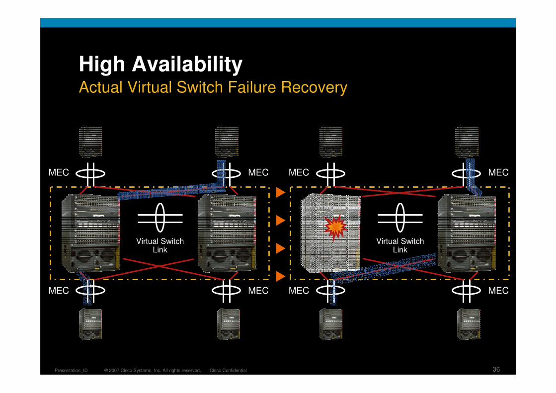
High AvailabilityActual Virtual Switch Failure Recovery
Virtual SwitchLink
MEC
MEC
MEC
MEC
Virtual SwitchLink
MEC
MEC
MEC
MEC

© 2007 Cisco Systems, Inc. All rights reserved. Cisco ConfidentialPresentation_ID 37
Virtual Switch System
� Upstream and Downstreamneighbors will view the Virtual Switch as a single Layer 2 switching node or as a single Layer 3 routing node thus reducing Layer 2/3 control protocol traffic
Benefits
VSL
MEC
MECMEC
Access L
aye
rC
ore
La
yer
Dis
trib
ution L
aye
r � Single Management PointAdministrators will see a single management point from which to configure and administer the VSS which includes a single consolidated configuration file for both physical switches
� Multi-Chassis EtherChannel allows a link bundle to terminate across twophysical Cisco Catalyst 6500 chassis
� As far as the other end is concerned, the link bundle is seen as terminating on the one physical device even though it is actually terminating across two chassis

© 2007 Cisco Systems, Inc. All rights reserved. Cisco ConfidentialPresentation_ID 38
Next Generation Campus Design
� Traditional Layer 2 designs remain valid
� Evolving architectures provide
Simplified Control Plane: Remove dependence on STP
Increased Capacity: Provide flow-based load balancing
High Availability: 200 msec or better recovery
� Flexibility to provide for the right implementation for each network requirement
Evolving the Campus Foundation Architecture
SiSi SiSi SiSi SiSi
SiSi SiSi

© 2007 Cisco Systems, Inc. All rights reserved. Cisco ConfidentialPresentation_ID 39
Resilient Campus Network DesignAgenda
Campus Design Foundation
Distribution Block Design Considerations
Fully Routed Campus
Cisco Catalyst 6500: Virtual Switching System
Access Layer Design Considerations
Architecture Enhancements
Availability
QoS
Security
Managing the Resilient Campus Distribution Blocks
SiSiSiSi
SiSiSiSi
SiSi
Data Center
SiSi SiSi
ServicesBlock
SiSi SiSi SiSi

© 2007 Cisco Systems, Inc. All rights reserved. Cisco ConfidentialPresentation_ID 40
Access Layer
� It’s not just about connectivity
� Layer 2/Layer 3 feature rich environment; convergence, HA, security, QoS, IP multicast, etc.
� Intelligent network services: QoS,trust boundary, broadcast suppression, IGMP snooping
� Intelligent network services: PVST+, Rapid PVST+, EIGRP, OSPF, DTP, PAgP/LACP, UDLD, FlexLink, etc.
� Cisco Catalyst integrated security features IBNS (802.1x), (CISF): port security, DHCP snooping, DAI, IPSG, etc.
� Automatic phone discovery, conditional trust boundary, power over Ethernet, auxiliary VLAN, etc.
� Spanning tree toolkit: Portfast, UplinkFast, BackboneFast, LoopGuard, BPDUGuard, BPDUFilter, RootGuard, etc.
SiSiSiSi
SiSiSiSi
Feature Rich Environment

© 2007 Cisco Systems, Inc. All rights reserved. Cisco ConfidentialPresentation_ID 41
Access Layer Network Services
� Phone contains a three-port switch that is dynamically configured by the access switch and Cisco Call Manager
Power negotiation
VLAN configuration
802.1x interoperation
QoS configuration
DHCP
Cisco CallManager® registration
Switch Detects IP Phone and Applies Power
CDP Transaction Between Phone and Switch
IP Phone Placed in Proper VLAN
DHCP Request and Call Manager Registration
Endpoints Dynamically Participate in the Overall Network QoS and Security
UC Integrated with Network QoS and Security
SiSi

© 2007 Cisco Systems, Inc. All rights reserved. Cisco ConfidentialPresentation_ID 42Data Center
Campus
Access Layer Network Services
� Application Traffic Requirements are evolving
� Desktop based Unified Communications
� Collaborative applications
� High Definition Video
� Web portals and front-ends leveraging common HTTP transport for a wide variety of business requirements
� Requirements for more granular application awareness in the network services, QoS, Security, HA, ...
Evolving Application Traffic Requirements
Application Intelligence,
Security and Flow
Information Required at All Layers
SiSi SiSi SiSi SiSi SiSi SiSi
SiSi SiSi
SiSi SiSi

© 2007 Cisco Systems, Inc. All rights reserved. Cisco ConfidentialPresentation_ID 43
Resilient Campus Network DesignAgenda
Campus Design Foundation
Distribution Block Design Considerations
Fully Routed Campus
Cisco Catalyst 6500: Virtual Switching System
Access Layer Design Considerations
Architecture Enhancements
Availability
QoS
Security
Managing the Resilient Campus Distribution Blocks
SiSiSiSi
SiSiSiSi
SiSi
Data Center
SiSi SiSi
ServicesBlock
SiSi SiSi SiSi

© 2007 Cisco Systems, Inc. All rights reserved. Cisco ConfidentialPresentation_ID 44
PFC3B
Supervisor 32 PISA
� PISA is a superset of the MSFC2a daughter card
� It contains both a faster Route Processor (RP) and a dedicated Network Processor
Improved Route Processor (750 MHz)
1GB RP DRAM by default
PISA CF bootdisk (256 MB)
� Network Processor provides HW accelerated L4-7 IP Services
� WS-S32P-10GE and WS-S32P-GE PISA Daughter Card
RP CPUClassificationand Dispatch Engine PISA
Micro Engines
CPU
Network
Processor
DRAM1 GB
32MSRAM
10G
DRAM768 MB
Hardware-Based Feature Acceleration

© 2007 Cisco Systems, Inc. All rights reserved. Cisco ConfidentialPresentation_ID 45
Supervisor 32 PISA
� Traffic is redirected to PISA when NBAR or FPM is configured on an interface—PISA acts as bump in the wire service
NBAR/FPM Configured on G1/9 Egress
PISA
G1/1 G1/8
G1/3 G1/10
No PISA Accelerated Feature Configured
G1/2 G1/9
NBAR/FPM Configured on
G1/1 Ingress
Traffic Flow through PISA
Traffic Flow bypassing PISA
Application Forwarding and Visibility

© 2007 Cisco Systems, Inc. All rights reserved. Cisco ConfidentialPresentation_ID 46
Cisco Catalyst 4500 E-Series: Centerflex
� Centralized 320 Gbps, 250 Mpps, L2/3/4
� IPv4 (250Mpps) and IPv6 (125Mpps) in HW
� Supports full redundancy with SSO/NSF/ISSU (7R and 10R)
� Four active 10GbE ports or Eight active SFPs in redundant mode
� 512MB DRAM (upgradeable to 1 Gig)
� 256K FIB entries, 128K security/QoS
� 3, 6, 7R, and 10R support
� Supports “classic” (6 Gig/slot) and “E”series line cards (24 gig/slot) with no performance degradation if mixed
WS-X45-Sup6-E
Dual Purpose Uplink Ports
Two 10 GbE or Four 1 GbE
with Twin Gig Module
Next Generation Centralized Architecture

© 2007 Cisco Systems, Inc. All rights reserved. Cisco ConfidentialPresentation_ID 47
Cisco Catalyst 4500 E-Series: CenterflexNext Generation Centralized Architecture
Feature Classic Performance E-Series Performance
Throughput 102M(IPv4)/30K(IPv6) 250(IPv4)/125(IPv6) Mpps
Transmit Queues 4 Queues Fixed8 Queues per Port
(MQC Model)
Configurable Queues
1P3Q1T1P7Q2T up to 8184 Queues
per Port/100K Pool
Flexible Policers 8K Ingress/8K Egress 16K in 2K Increments
Security and QoS ACE
64K 128K Flexible
MLDv2 Snooping No Yes
EtherChannel 64 with Global Balancing512 with Per-Channel Load
Balancing Algorithm
SPAN/RSPAN 6 Sessions 8 Sessions
URPF No Strict Mode
Output Policy on Input Marketing
No Yes
© 2007 Cisco Systems, Inc. All rights reserved. Cisco ConfidentialPresentation_ID 48
Resilient Campus Network DesignAgenda
Campus Design Foundation
Distribution Block Design Considerations
Fully Routed Campus
Cisco Catalyst 6500: Virtual Switching System
Access Layer Design Considerations
Architecture Enhancements
Availability
QoS
Security
Managing the Resilient Campus Distribution Blocks
SiSiSiSi
SiSiSiSi
SiSi
Data Center
SiSi SiSi
ServicesBlock
SiSi SiSi SiSi

© 2007 Cisco Systems, Inc. All rights reserved. Cisco ConfidentialPresentation_ID 49
Access Layer Design: Topology
� Daisy chained access switches rely on STP between members of the ‘pile’
� Unicast flooding is common in daisy chained access switch networks
� If you use modular (chassis based) switches these problems are not a concern
Loopback links not required
No longer forced to have L2 link in distribution
Daisy Chaining Access Layer Switches
GLBP Active
GLBP Active
ForwardingForwarding
Layer 3
SiSi SiSi
SiSi
HSRP Active
HSRP Standby
Layer 2
B
SiSi SiSi
Blocking

© 2007 Cisco Systems, Inc. All rights reserved. Cisco ConfidentialPresentation_ID 50
Access
Distribution
Core10GE and
10GE Channels
Typical 20:1
Data Over-Subscription
Typical 4:1
Data Over-Subscription
Access Layer Design: Capacity10/100/1000 Access and Distribution/Core Aggregation
SiSiSiSiSiSi SiSiSiSiSiSi
SiSiSiSiSiSiSiSiSiSiSiSi
© 2007 Cisco Systems, Inc. All rights reserved. Cisco ConfidentialPresentation_ID 51
Access Layer Design: Availability
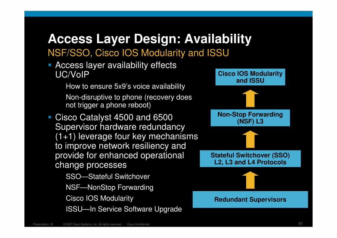
� Access layer availability effects UC/VoIP
How to ensure 5x9’s voice availability
Non-disruptive to phone (recovery does not trigger a phone reboot)
� Cisco Catalyst 4500 and 6500 Supervisor hardware redundancy (1+1) leverage four key mechanisms to improve network resiliency and provide for enhanced operational change processes
SSO—Stateful Switchover
NSF—NonStop Forwarding
Cisco IOS Modularity
ISSU—In Service Software Upgrade
Stateful Switchover (SSO)L2, L3 and L4 Protocols
Non-Stop Forwarding (NSF) L3
Cisco IOS Modularity and ISSU
Redundant Supervisors
NSF/SSO, Cisco IOS Modularity and ISSU

© 2007 Cisco Systems, Inc. All rights reserved. Cisco ConfidentialPresentation_ID 52
Access Switch Supervisor Redundancy
� Non-Stop Forwarding provides graceful restart enhancements to EIGRP, OSPF, IS-IS and BGP
� An NSF-capable router continuously forwards packets during an SSO processor recovery
� NSF-aware and NSF-capable routers provide for transparent routing protocol recovery
Graceful restart extensions enable neighbor recovery without resetting adjacencies
Routing database re-synchronization occurs in the background
NSF-Aware, NSF-Capable
NSF-Aware
NSF-Aware
Routing Protocol Graceful Restart Capabilities NSF)
SiSi SiSi
SiSi SiSi

© 2007 Cisco Systems, Inc. All rights reserved. Cisco ConfidentialPresentation_ID 53
Access Design Considerations for NSF/SSO
� Cisco Catalyst 4500 E-Series
All uplinks can active on both Supervisors
Uplink ports do not go down during SSO recovery
� Cisco Catalyst 6500
All uplinks are active on both Supervisors
Uplink ports go down when the supervisor is reset
Recommended to run 12.2(18)SXF5 or later when using Supervisor uplinks to carry L3 traffic (routed ports or SVI)
Recommended to run 12.2(18)SXF12 when using Supervisor uplinks configured as an EtherChannel to carry L3 traffic
1/1 1/2
2/1 2/2
Cisco Catalyst 6500 Supervisors: All Ports Are Active
Cisco Catalyst 4500 Supervisor 6-E All Uplinks Can Be Active
(2:1 Oversubscribed)
Supervisor Uplinks
1/1 1/2
2/1 2/2
2:1 Oversubscribed
No Over Subscription

© 2007 Cisco Systems, Inc. All rights reserved. Cisco ConfidentialPresentation_ID 54
Supervisor V
Supervisor II+10GE
Supervisor II+, Supervisor IV
1/1 1/2
2/1 2/2
1/1 1/2
2/1 2/2
1/1 1/3 1/4 1/5 1/61/2
2/1 2/3 2/4 2/5 2/62/2
4 x GigE Ports Are Active Concurrently
2 x 10GE and 4 x GigE Ports Are Active
Supervisor V-10GE
2 x 10GE and 4 x GigE Ports Are Active1/1 1/3 1/4 1/5 1/61/2
2/1 2/3 2/4 2/5 2/62/2
Cisco Catalyst 4500 Series Classic SupervisorUplink Redundancy as of 12.2(25)SG
2 x GigE Ports Are Active
© 2007 Cisco Systems, Inc. All rights reserved. Cisco ConfidentialPresentation_ID 55
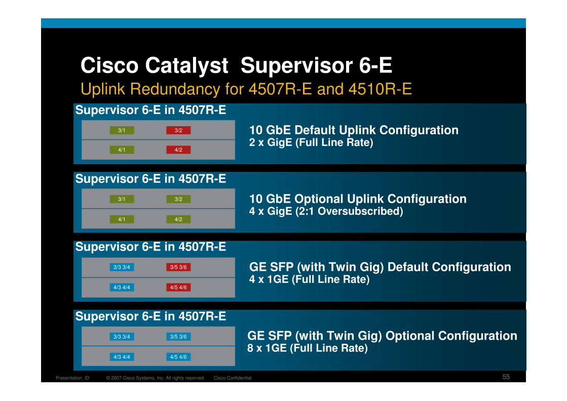
Cisco Catalyst Supervisor 6-EUplink Redundancy for 4507R-E and 4510R-E
10 GbE Optional Uplink Configuration4 x GigE (2:1 Oversubscribed)
GE SFP (with Twin Gig) Default Configuration4 x 1GE (Full Line Rate)
GE SFP (with Twin Gig) Optional Configuration8 x 1GE (Full Line Rate)
10 GbE Default Uplink Configuration2 x GigE (Full Line Rate)
Supervisor 6-E in 4507R-E
Supervisor 6-E in 4507R-E
Supervisor 6-E in 4507R-E
Supervisor 6-E in 4507R-E
3/1 3/2
4/1 4/2
3/1
4/1
3/2
4/2
3/3 3/4 3/5 3/6
4/3 4/4 4/5 4/6
3/3 3/4 3/5 3/6
4/3 4/4 4/5 4/6

© 2007 Cisco Systems, Inc. All rights reserved. Cisco ConfidentialPresentation_ID 56
Line Card
Line Card
Line Card
Line Card
Line Card
Active SupervisorActive Supervisor
Standby SupervisorStandby SupervisorActive SupervisorActive Supervisor
Standby SupervisorStandby Supervisor
� ISSU provides a mechanism to perform software upgrades and downgrades without taking the switch out of service
� Leverages the capabilities of NSF and SSO to allow the switch to forward traffic during supervisor IOS upgrade (or downgrade)
� Network does not re-route and no active links are taken out of service
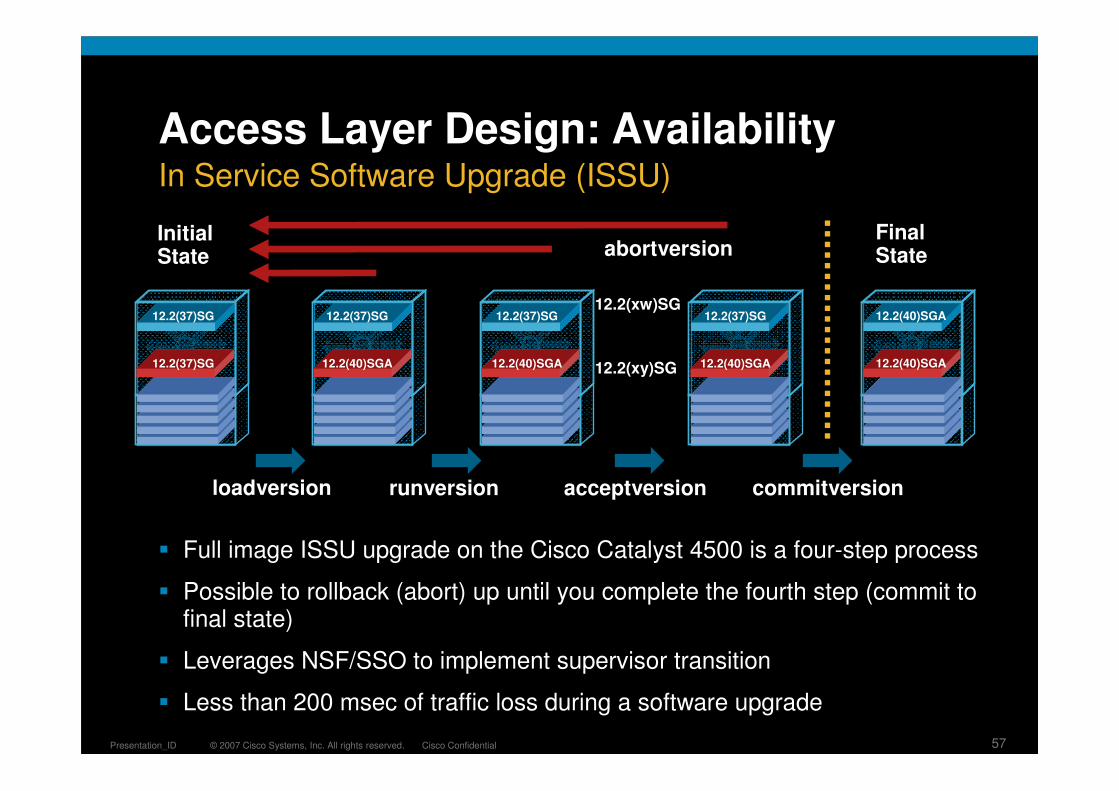
12.2(37)SG
12.2(40)SG
Access Layer Design - AvailabilityIn Service Software Upgrade (ISSU)
© 2007 Cisco Systems, Inc. All rights reserved. Cisco ConfidentialPresentation_ID 57
12.2(xy)SG
12.2(xw)SG
loadversion runversion acceptversion commitversion
abortversion
Access Layer Design: Availability
� Full image ISSU upgrade on the Cisco Catalyst 4500 is a four-step process
� Possible to rollback (abort) up until you complete the fourth step (commit to final state)
� Leverages NSF/SSO to implement supervisor transition
� Less than 200 msec of traffic loss during a software upgrade
Initial State
Final State
In Service Software Upgrade (ISSU)
12.2(37)SG
12.2(37)SG
12.2(37)SG
12.2(40)SGA
12.2(37)SG
12.2(40)SGA
12.2(37)SG
12.2(40)SGA
12.2(40)SGA
12.2(40)SGA

© 2007 Cisco Systems, Inc. All rights reserved. Cisco ConfidentialPresentation_ID 58
.0
.2
.4
.6
.8
1.0
NSF-Enabled Optimal NSF-Enabled Maximum
Se
co
nd
s o
f L
os
t V
oic
eAccess Layer Design: Availability
� Access switch is the single point of failure in best practices HA campus design
� Supervisor failure is most common cause of access switch service outages after L1 failures (power and fiber)
� Recommended design NSF/SSO provides for sub second recovery of voice and data traffic
Access Switch Supervisor Redundancy
SiSi SiSi
SiSi SiSi

© 2007 Cisco Systems, Inc. All rights reserved. Cisco ConfidentialPresentation_ID 59
Resilient Campus Network DesignAgenda
Campus Design Foundation
Distribution Block Design Considerations
Fully Routed Campus
Cisco Catalyst 6500: Virtual Switching System
Access Layer Design Considerations
Architecture Enhancements
Availability
QoS
Security
Managing the Resilient Campus Distribution Blocks
SiSiSiSi
SiSiSiSi
SiSi
Data Center
SiSi SiSi
ServicesBlock
SiSi SiSi SiSi

© 2007 Cisco Systems, Inc. All rights reserved. Cisco ConfidentialPresentation_ID 60
“The Real-Time Interactive service class should… be configured to provide a high assurance for bandwidth for CS4 marked packets toensure that they get forwarded…
Note that this service class may be configured as a second EF PHBthat uses relaxed performance parameter, a rate scheduler, and CS4 DSCP value.” RFC 4594 Section 4.4
© 2007 Cisco Systems, Inc. All rights reserved. Cisco ConfidentialPresentation_ID 60
New Traffic RequirementsHigh Definition Video Needs a Separate Class
Service Level Parameter
(Generic)Video-Conferencing
CiscoTelePresence®
Bandwidth (Max)384 kbps or 768 kbps +
Network Overhead2.5 Mbps to 12.6 Mbps +
Network Overhead
Latency (Max) 400–450 ms 150–400 ms
Jitter (Max) 30–50 ms Peak-to-Peak 10 ms Peak-to-Peak
Loss (Max) 1% Random Packet Loss 0.05% Random Packet Loss

© 2007 Cisco Systems, Inc. All rights reserved. Cisco ConfidentialPresentation_ID 61
4/5 Class Model
Scavenger
Critical Data
Call Signaling
Best Effort
Real Time
8-Class Model
Critical Data
Video
Call Signaling
Best Effort
Voice
Bulk Data
Network Control
Scavenger
11-Class Model
Network Management
Call Signaling
Streaming Video
Transactional Data
Interactive-Video
Voice
Best Effort
IP Routing
Mission-Critical Data
Scavenger
Bulk Data
Time
How Many Classes Does the Campus Need?Expanding the Number of Classes of Service over Time

© 2007 Cisco Systems, Inc. All rights reserved. Cisco ConfidentialPresentation_ID 62
Expanding the Number of Classes of Service
Supervisor II+, II+10GE, IV, V, V-10GE
� Four queues (1P3Q1T)
� Fixed queue size
� Q3 is priority queue
Supervisor 6-E
� Configurable up to eight queues (1P7Q2T) with configurable thresholds
� Queue size configurable up to 8184 packets per queue (100K Pool)
� Class based queuing
� User configurable priority queue
Flexible Resources
Supervisor 6-E with CenterFlex
Four Static Tx Queues per Port
Eight User Configurable Tx Queues per Port
Classic Supervisors
Cisco Catalyst 4500E Enhanced Queuing

© 2007 Cisco Systems, Inc. All rights reserved. Cisco ConfidentialPresentation_ID 63
SiSi
Voice VLAN Traffic Is Trusted
Voice and Video Traffic on the Data VLAN Traffic
Data VLAN Traffic Untrusted Marked CoS 0
PISA Remarks RTP Flows to Correct DSCP
Extended Trust Boundary Intelligent Trust Boundary
UC Applications Migrating to the PC
� With auto-qos configured default switch behavior is to not trust edge ports and remark all traffic to configured CoS/DSCP
� When switch and phone exchange CDP the trust boundary is extended to IP phone
� Phone rewrites CoS from PC port to ‘0’, switch rewrites DSCP
� Sup32 PISA provides an intelligent QoS remarking override for specificallydefined applications on the Data VLAN
Need for an Enhanced QoS Trust Boundary

© 2007 Cisco Systems, Inc. All rights reserved. Cisco ConfidentialPresentation_ID 64
Enhanced Access Trust Boundary
� HW NBAR works together with QoS to assign QoS actions based on application classification
� Modular QoS traffic classification:
Define match criteria (class-map)
Associate actions for a given match criteria in a policy-map
Assign policy to an interface
� New match criteria: “match protocol <protocol_name>”
Policy Map
Class Map
Policing/Trust Actions
Policy Map can contain up to 32 class maps
Refers to a set of classification criteria for the following action criteria—these can be DSCP, ACL, or protocol
Action settings for trust and policing
Sw
itch
Inte
rface
(config)#policy-map NBAR_policy(config-pmap)#class-map myApp
(config)#class-map myApp(config-cmap)#match access-group 101(config-cmap)#match protocol http (config-cmap)#match protocol rtp
(config)#policy-map NBAR_policy(config-pmap)#class-map myApp(config-pmap)#set dscp 40
PISA NBAR and MQC QoS

© 2007 Cisco Systems, Inc. All rights reserved. Cisco ConfidentialPresentation_ID 65
NBAR Real-Time Transport Protocol
� Eases classification of voice and video traffic
� Distinguishes between RTP packets based on payload type and CODECS
� Removes dependencies on UDP Port Range and DSCP markings
� Example
NBAR to match RTP traffic with the payload-types 0, 1, 4, 5, 6, 7, 8, 9, 10, 11, 12, 13, 14, 15, 16, 17, 18, 64
match protocol rtp payload-type "0, 1, 4 - 0x10, 10001b - 10010b, 64“
Classification of UC Applications
CODEC Payload Type
G.711 (Audio)0 (mu-law)8 (a-law)
G.721 (Audio) 2
G.722 (Audio) 9
G.723 (Audio) 4
G.728 (Audio) 15
G.729 (Audio) 18
H.261 (Video) 31
MPEG-1 (A/V)MPEG-2 (A/V)
14 (Audio)32 (Video)33 (A-V)
Dynamic 96–127

© 2007 Cisco Systems, Inc. All rights reserved. Cisco ConfidentialPresentation_ID 66
PISA Identifies and Remarks HTTP Flows to Desired DSCP
match protocol http user-agent *Mozilla/4.0*match protocol http referer *http://www.cisco.com/go/nbar*
PISA(config-cmap)#match protocol http ?
content-encoding Encoding mechanism used to package entity body
from E-mail of human controlling the user-agent
host Host name of Origin Server containing resource
location Exact location of resource from request
mime Content-Type of entity body
referer Address the resource request was obtained from
server Software used by Origin Server handling request
url Uniform Resource Locator path
user-agent Software used by agent sending the request
<cr>
HTTP Port Overloading
� Migration to common HTTP interface for multiple applications
� Challenge to distinguish priority based on port numbers
� NBAR deep packet inspection allows marking based on HTTP content
NBAR HTTP Identification and Classification
SiSi

© 2007 Cisco Systems, Inc. All rights reserved. Cisco ConfidentialPresentation_ID 67
Sup32-PISA#show ip nbar protocol-discovery top-n 5
Vlan611 Input Output ----- ------
Protocol Packet Count Packet Count Byte Count Byte Count 5min Bit Rate (bps) 5min Bit Rate (bps) 5min Max Bit Rate (bps) 5min Max Bit Rate (bps)
------------------------ ------------------------ ------------------------Remote_Desktop 319 252
157009 47083 0 0 7000 3000
icmp 1591 1591 162282 162282 1000 1000 1000 1000
NBAR Protocol Discovery
� NBAR Protocol Discovery: discover what apps are running on your network and provide real-time statistics
� Per-interface, per-protocol, bi-directional statistics (bit rate (bps); packet count; byte count)
� SNMP accessible for centralized monitoring
� Supported by Partner products (Concord, CA, InfoVista, Micromuse, IBM) and MRTG
Real-Time Application Visibility

© 2007 Cisco Systems, Inc. All rights reserved. Cisco ConfidentialPresentation_ID 68
Resilient Campus Network DesignAgenda
Campus Design Foundation
Distribution Block Design Considerations
Fully Routed Campus
Cisco Catalyst 6500: Virtual Switching System
Access Layer Design Considerations
Architecture Enhancements
Availability
QoS
Security
Managing the Resilient Campus Distribution Blocks
SiSiSiSi
SiSiSiSi
SiSi
Data Center
SiSi SiSi
ServicesBlock
SiSi SiSi SiSi

© 2007 Cisco Systems, Inc. All rights reserved. Cisco ConfidentialPresentation_ID 69
Controlling Access to the Network
� FBI/CSI Risk Assessment*
Many enterprises network ports are open
Usually any laptop can plug into the network and gain access to the network
Of companies surveyed total loss was over $130 million
Average spending per employee $247 per year
78% said about inside attacks—they did not know if they were under attack
� Secure Access beyond a locked door
Query for Identity
� Inspect Devices for Posture
Check OS Patch Levels
Validate Desktop Security Tools
Who and What Is Connecting to the Network?
*CIS/FBI Computer Crime and Security Survey—2005; http://www.gocsi.com/

© 2007 Cisco Systems, Inc. All rights reserved. Cisco ConfidentialPresentation_ID 70
IP Source Guard
Dynamic ARPInspection
DHCPSnooping
Port Security
Hardening the EdgeCisco Catalyst Integrated Security Features
00:0e:00:aa:aa:aa00:0e:00:bb:bb:bb00:0e:00:aa:aa:cc00:0e:00:bb:bb:ddetc.
132,000 Bogus MACs
Switch Acts Like
a Hub
DHCP Server
X
“Use this IP Address !”
Email Server
Man in the Middle
“Your Email Passwd Is
‘joecisco’ !”
� Port Security prevents CAM attacks, DHCP Starvation attacks and spanning tree loop mitigation
� DHCP Snooping prevents Rogue DHCP Server attacks
� Dynamic ARP Inspection prevents current ARP attacks
� IP Source Guard prevents IP/MAC Spoofing and a wide variety of TCP/UDP splicing and DoS attacks
© 2007 Cisco Systems, Inc. All rights reserved. Cisco ConfidentialPresentation_ID 71
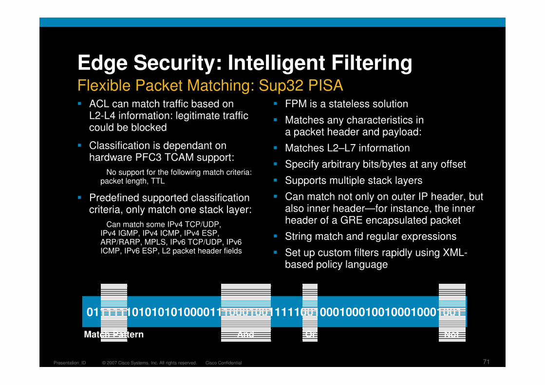
Edge Security: Intelligent Filtering
� ACL can match traffic based on L2-L4 information: legitimate traffic could be blocked
� Classification is dependant on hardware PFC3 TCAM support:
No support for the following match criteria: packet length, TTL
� Predefined supported classification criteria, only match one stack layer:
Can match some IPv4 TCP/UDP, IPv4 IGMP, IPv4 ICMP, IPv4 ESP, ARP/RARP, MPLS, IPv6 TCP/UDP, IPv6 ICMP, IPv6 ESP, L2 packet header fields
� FPM is a stateless solution
� Matches any characteristics in a packet header and payload:
� Matches L2–L7 information
� Specify arbitrary bits/bytes at any offset
� Supports multiple stack layers
� Can match not only on outer IP header, but also inner header—for instance, the inner header of a GRE encapsulated packet
� String match and regular expressions
� Set up custom filters rapidly using XML-based policy language
0111111010101010000111000100111110010001000100100010001001
Match Pattern And Or Not
Flexible Packet Matching: Sup32 PISA

© 2007 Cisco Systems, Inc. All rights reserved. Cisco ConfidentialPresentation_ID 72
class-map type access-control match-all slammerdescription "match on slammer packets"
match field UDP dest-port eq 1434
match field IP length eq 404
match start UDP payload-start offset 196 size 4 eq 0x4011010
class-map type access-control match-all gnutellamatch start TCP payload-start offset 0 size 32 regex "^GNUTELLA CONNECT“
class-map type access-control match-any cm-nimda1match start l3-start offset 40 size 32 regex "[\\/]csrss\.exe"
match start l3-start offset 40 size 32 regex "[\\/]httpodbc\.dll"
match start l3-start offset 40 size 32 regex "[\\/]sample\.exe"
match start l3-start offset 40 size 32 regex "[\\/]dnsservice\.exe"
match start l3-start offset 40 size 32 regex "[\\/]puta\.eml"
match start l3-start offset 40 size 32 regex "[\\/]puta\.scr"
match start l3-start offset 40 size 32 regex "[\\/]readme\.eml"
IP UDP
IP TCP
Payload
Payload
HTTPIP TCP
Stack
Stack
Stack
Slammer
Gnutella
Nimda
Edge Security: Intelligent Filtering
� Traffic matching a given protocol stack is subject to an FPM Deep Packet inspection rule
� Supports pattern matching through regular expressions and stringmatching: up to 48 regular expressions (32 Bytes window in 12.2(18)ZY)
IP UDP
IP TCP
Payload
Payload
HTTPIP TCP
Slammer
Gnutella
Nimda
Defining the FPM Rule

© 2007 Cisco Systems, Inc. All rights reserved. Cisco ConfidentialPresentation_ID 73
Resilient Campus Network DesignAgenda
Campus Design Foundation
Distribution Block Design Considerations
Fully Routed Campus
Cisco Catalyst 6500: Virtual Switching System
Access Layer Design Considerations
Architecture Enhancements
Availability
QoS
Security
Managing the Resilient Campus Distribution Blocks
SiSiSiSi
SiSiSiSi
SiSi
Data Center
SiSi SiSi
ServicesBlock
SiSi SiSi SiSi

© 2007 Cisco Systems, Inc. All rights reserved. Cisco ConfidentialPresentation_ID 74
Enhanced System Stability
Enhanced Network Stability
Proactive Fault Detection and Reaction
� Challenge: In today’s highly available networks improved physical redundancy is not enough, intelligent system failure detection and recovery are key
Detect and
Isolate
Generic Online Diagnostics (GOLD) Provides Proactive,
Scheduled and Manual
System Diagnostics
Link Faults
Memory Corruption
Software Inconsistency
System Faults
Enhanced Object Tracking
(EOT), Embedded Event Manager (EEM), and Smart Call Home (SCH) Provide
Intelligent Response to System Events
Distributed Management Intelligence

© 2007 Cisco Systems, Inc. All rights reserved. Cisco ConfidentialPresentation_ID 75
Integrated System Operations Toolkit
� Generic Online Diagnostics (GOLD) can proactively detect software and hardware malfunctions before they adversely impact network traffic
Proactive Diagnostics
Customizable System Reaction
� Embedded Event Manager (EEM) allows customizable reaction to GOLD detected events or Cisco IOS counters and events
� Smart Call Home provides automated operations and TAC notification for critical network systems events
Improved Analysis Tools
� System Event Archive (SEA) maintains a secure log of system events and critical messages across reboots
� On Board Failure Logging (OBFL) is like a “black box” recorder on each line card that records diagnostic and environmental information
Detect, React, and Analyze

© 2007 Cisco Systems, Inc. All rights reserved. Cisco ConfidentialPresentation_ID 76
Switch#diagnostic start module 1 test 2 port 1
Module 1: Running test(s) 2 may disrupt normal system operation
Do you want to continue? [no]: yes13:50:01: %DIAG-SP-6-TEST_RUNNING: Module 1: Running TestLoopback{ID=2} ...
13:50:01: %DIAG-SP-6-TEST_OK: Module 1: TestLoopback{ID=2} has completed successfully
Generic Online Diagnostics
� Test is disruptive for the tested port (subseconds)
� Verifies the tested port functionality and the datapath
� Newer linecards support non-disruptive loopback tests: ten consecutive failures are treated as fatal and will result in port being error-disabled
PFC3L3/4
Engine
MSFCPort ASIC
RP CPU
SP CPU
DBUSRBUS
16 GbpsBus
EOBC
L2 Engine FabricInterface
Switch Fabric
ClassicModule Port
ASICPortASIC
An Example: Loopback Test—Line card Data Path Coverage
”show diagnostic content module X”to see available tests and their impact
© 2007 Cisco Systems, Inc. All rights reserved. Cisco ConfidentialPresentation_ID 77
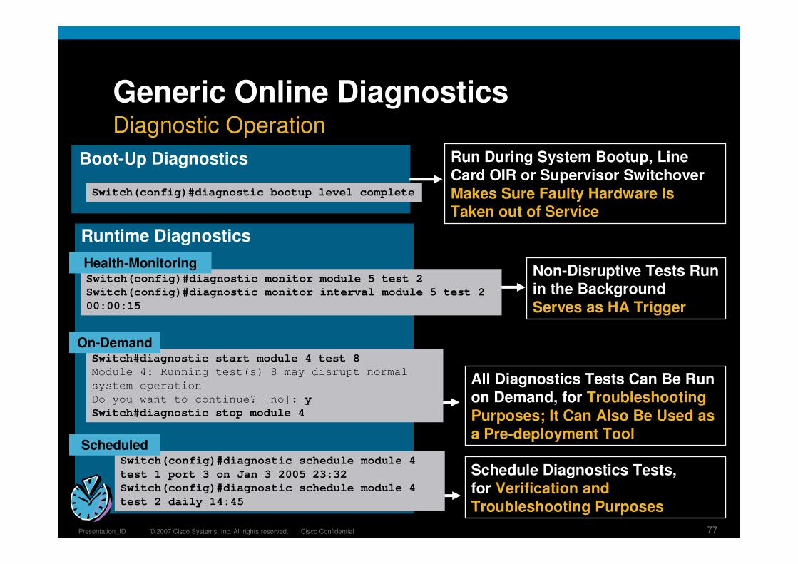
Switch(config)#diagnostic monitor module 5 test 2
Switch(config)#diagnostic monitor interval module 5 test 2
00:00:15
Switch(config)#diagnostic bootup level complete
Switch#diagnostic start module 4 test 8
Module 4: Running test(s) 8 may disrupt normal
system operation
Do you want to continue? [no]: y
Switch#diagnostic stop module 4
Switch(config)#diagnostic schedule module 4
test 1 port 3 on Jan 3 2005 23:32
Switch(config)#diagnostic schedule module 4
test 2 daily 14:45
On-Demand
Health-Monitoring
Scheduled
Run During System Bootup, Line Card OIR or Supervisor Switchover
Makes Sure Faulty Hardware Is Taken out of Service
Non-Disruptive Tests Run in the Background
Serves as HA Trigger
All Diagnostics Tests Can Be Run on Demand, for Troubleshooting
Purposes; It Can Also Be Used as a Pre-deployment Tool
Schedule Diagnostics Tests, for Verification and
Troubleshooting Purposes
Boot-Up Diagnostics
Runtime Diagnostics
Generic Online DiagnosticsDiagnostic Operation
© 2007 Cisco Systems, Inc. All rights reserved. Cisco ConfidentialPresentation_ID 78
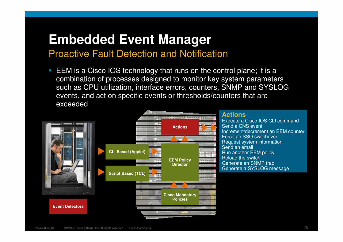
Embedded Event Manager
� EEM is a Cisco IOS technology that runs on the control plane; it is a combination of processes designed to monitor key system parameters such as CPU utilization, interface errors, counters, SNMP and SYSLOG events, and act on specific events or thresholds/counters that are exceeded
Proactive Fault Detection and Notification
Actions
EEM PolicyDirector
Cisco MandatoryPolicies
Script Based (TCL)
CLI Based (Applet)
ActionsExecute a Cisco IOS CLI commandSend a CNS eventIncrement/decrement an EEM counterForce an SSO switchoverRequest system informationSend an emailRun another EEM policyReload the switchGenerate an SNMP trapGenerate a SYSLOG message
Event Detectors

© 2007 Cisco Systems, Inc. All rights reserved. Cisco ConfidentialPresentation_ID 79
Embedded Event Manager
SY
SL
OG
Eve
nt
De
tecto
r
SN
MP
Eve
nt
De
tec
tor
Tim
er
Eve
nt
De
tec
tor
Co
un
ter
Eve
nt
De
tec
tor
I/F
Co
un
ter
Eve
nt
De
tec
tor
CL
E E
ve
nt
De
tec
tor
OIR
Eve
nt
De
tec
tor
No
ne
Eve
nt
De
tec
tor
RF
Eve
nt
De
tec
tor
IOS
Wa
tch
do
g E
ve
nt
De
tec
tor
GO
LD
Eve
nt
De
tec
tor
Ap
pli
ca
tio
n E
ve
nt
De
tec
tor
SY
S M
an
ag
er
Eve
nt
De
tec
tor
SY
S M
on
ito
r E
ve
nt
De
tec
torSNMP
Agent
IOS IDB’sIOS CLI
RIBOIR
SYSLOGHA
RoutingCountersMemory
Embedded Event Manager ServerEEM Event Detector API
EEM Event Client API
EEM Policy
Events Event Detectors
EEM Policy DirectorSubscribes to Events and Implements Actions
Architecture
© 2007 Cisco Systems, Inc. All rights reserved. Cisco ConfidentialPresentation_ID 80
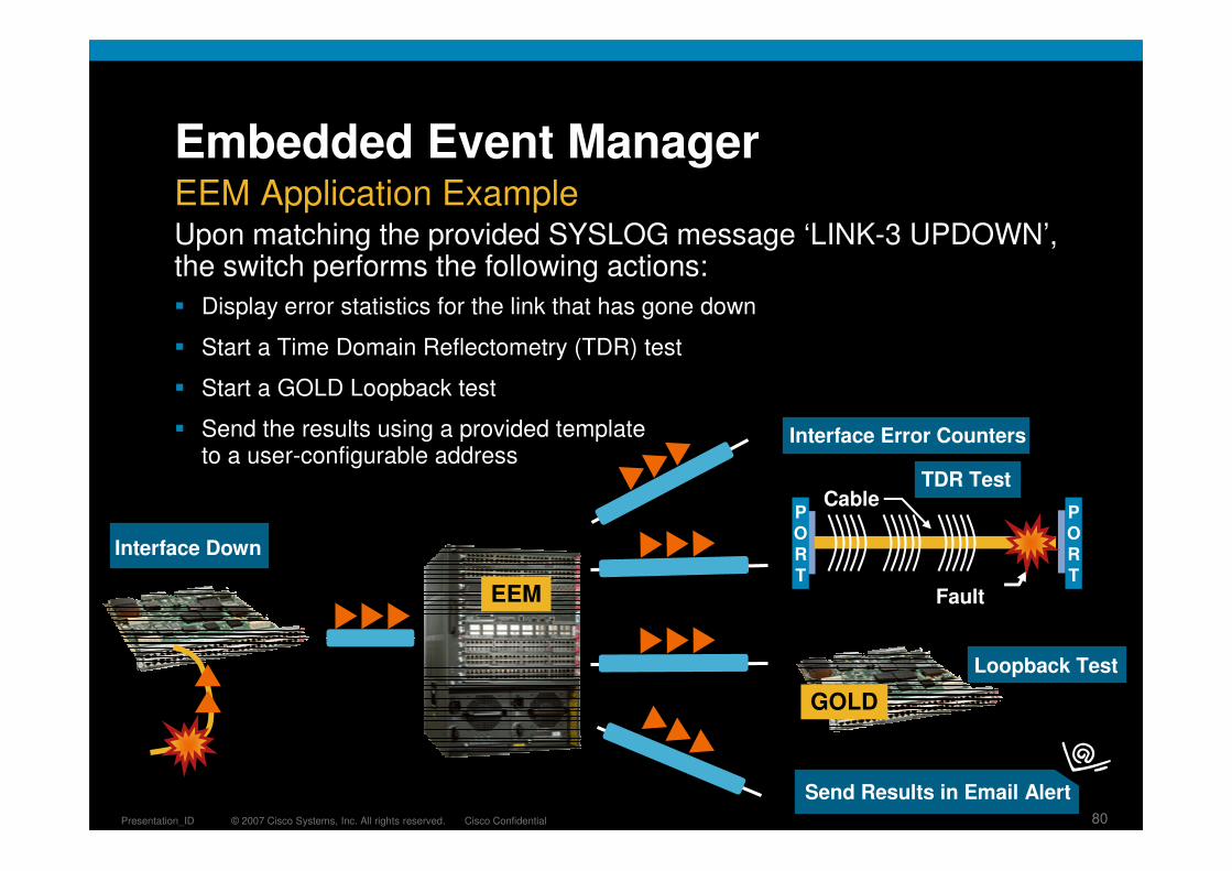
� Display error statistics for the link that has gone down
� Start a Time Domain Reflectometry (TDR) test
� Start a GOLD Loopback test
� Send the results using a provided templateto a user-configurable address
Upon matching the provided SYSLOG message ‘LINK-3 UPDOWN’, the switch performs the following actions:
Embedded Event ManagerEEM Application Example
Interface Down
Loopback Test
GOLD
EEM
Interface Error Counters
Send Results in Email Alert
Cable
Fault
PORT
PORT
TDR Test

© 2007 Cisco Systems, Inc. All rights reserved. Cisco ConfidentialPresentation_ID 81
Embedded Event Manager
event manager applet TEST
event syslog pattern "%LINK-3-UPDOWN: Interface GigabitEthernet7/1" maxrun 20
action 1.0 cli command “en”
action 2.0 cli command "test cable-diagnostics tdr interface G7/1“
action 3.0 cli command “diagnostic start module 7 test 2 port 1"
action 4.0 mail server “x.x.x.x" to “[email protected]" from "Switch-1" subject "Urgent! Interface went down" body "G7/1 went down"
event manager environment _email_server <IP_address>
event manager environment _email_to [email protected]
event manager environment _syslog_pattern .*UPDOWN.*state to down.*
event manager environment _email_from [email protected]
event manager environment intchk_template disk1:/interfacecheck.template
event manager directory user policy disk1:/
event manager policy interfacecheck.tcl
EEM Applet Example
EEM TCL Script Example
::cisco::eem::event_register_syslog occurs 1 pattern $_syslog_pattern maxrun 90
# EEM policy to monitor for a specified syslog message.
# check if all the env variables we need exist
<snip>
namespace import ::cisco::eem::*
namespace import ::cisco::lib::*
# The Body of the code goes here
<snip>
Configuration Example

© 2007 Cisco Systems, Inc. All rights reserved. Cisco ConfidentialPresentation_ID 82
Embedded Event Manager
� New on Cisco.com
� /go/ciscobeyond
� Open source scripts, share, upload, download, learn by example
� Categories include: Ntwk mgmt, routing, QoS, High availability, User interface, etc.
� Comments, ratings, community-managed forum
Cisco Beyond: Product Extension Community
http://cisco.com/go/ciscobeyond

© 2007 Cisco Systems, Inc. All rights reserved. Cisco ConfidentialPresentation_ID 83
37) TestErrorCounterMonitor ---------> F
Error code ------------------> 1 (DIAG_FAILURE)Total run count -------------> 2484Last test execution time ----> Feb 01 2007 10:55:52First test failure time -----> Jan 31 2007 11:55:17Last test failure time ------> Feb 01 2007 10:55:52Last test pass time ---------> Jan 31 2007 11:54:45Total failure count ---------> 2474Consecutive failure count ---> 2474
Error Records as following.ID -- Asic IdentificationIN -- Asic InstancePO -- Asic Port NumberRE -- Register IdentificationRM -- Register Identification MoreEG -- Error GroupDV -- Delta ValueCF -- Consecutive FailureTF -- Total Failure
ID IN PO RE RM DV EG CF TF---------------------------------------------------------------
49 0 255 240 255 8 2 2483 2483
Customer
Indicated developing unrecoverable failure. This is usually a problem related to improper grounding or excessive radiation emitted into the device. Make sure that the device is properly grounded and that neighboring devices are not emitting excessive radiation levels.
Smart Call Home
ASIC # 49, Register #240 Failed 2483 Consecutive Times
Indicates Single Bit ECC Errors Detected and Recovered
Smart Call Home
AutomatedDiagnosisCapability
Proactive Problem Identification
Call Home

© 2007 Cisco Systems, Inc. All rights reserved. Cisco ConfidentialPresentation_ID 84
Proactive Fault Detection and Reaction
� Improved fault detection and faster reaction to events
Generic Online Diagnostics (GOLD)
Embedded Event Manager (EEM) and Enhanced Object Tracking (EOT)
Smart Call Home (SCH)
� More visibility into actual state of applications and the network
NetFlow
IP SLA
NBAR
ERSPAN
Distributed and Embedded Operations
EOT
CLI
EEM
GOLD
NetFlow
IP SLA
NBAR
ERSPAN

© 2007 Cisco Systems, Inc. All rights reserved. Cisco ConfidentialPresentation_ID 85


![[XLS]fba.flmusiced.org · Web view1 1 1 1 1 1 1 2 2 2 2 2 2 2 2 2 2 2 2 2 2 2 2 2 2 2 2 2 2 2 3 3 3 3 3 3 3 3 3 3 3 3 3 3 3 3 3 3 3 3 3 3 3 3 3 3 3 3 3 3 3 3 3 3 3 3 3 3 3 3 3 3 3](https://img.pdfslide.us/doc/110x75/5b1a7c437f8b9a28258d8e89/xlsfba-web-view1-1-1-1-1-1-1-2-2-2-2-2-2-2-2-2-2-2-2-2-2-2-2-2-2-2-2-2-2.jpg)