Embed Size (px)
Citation preview

Resilient Alternative PNT Capabilities
for Aviation to Support Continued
Performance Based Navigation
Presented by Sherman Lo
International Technical Symposium on Navigation & Timing
ENAC, Toulouse, France
November 17, 2015
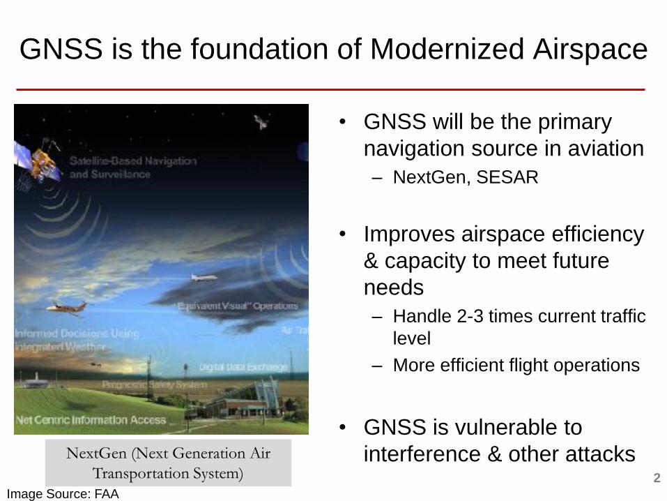
GNSS is the foundation of Modernized Airspace
• GNSS will be the primary
navigation source in aviation
– NextGen, SESAR
• Improves airspace efficiency
& capacity to meet future
needs
– Handle 2-3 times current traffic
level
– More efficient flight operations
• GNSS is vulnerable to
interference & other attacks
NextGen (Next Generation Air
Transportation System)
Image Source: FAA
2
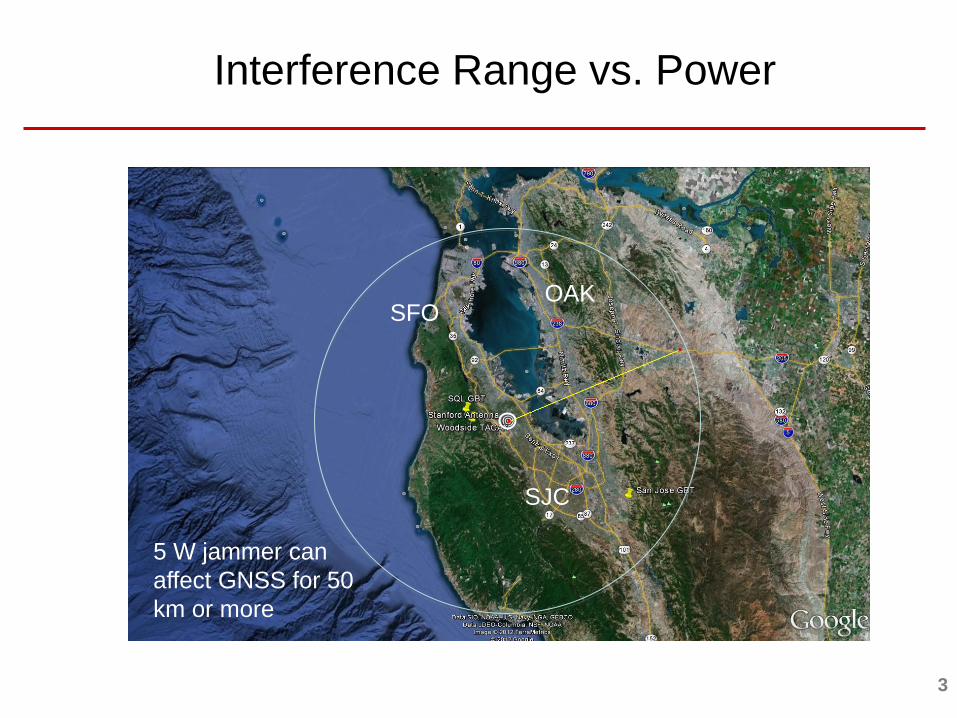
Interference Range vs. Power
3
5 W jammer can
affect GNSS for 50
km or more
SFO OAK
SJC
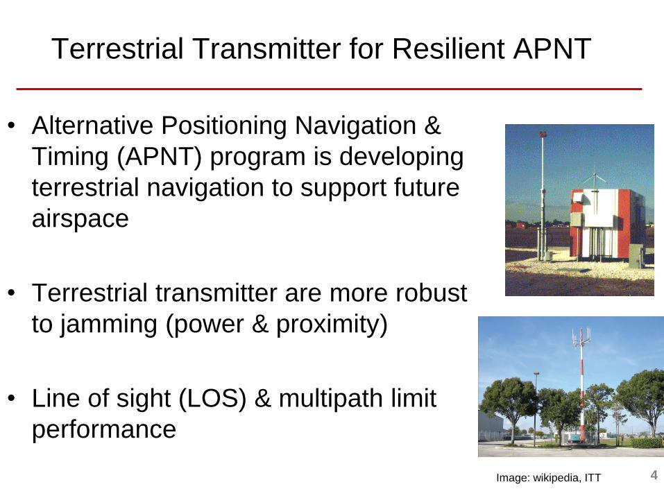
Terrestrial Transmitter for Resilient APNT
• Alternative Positioning Navigation &
Timing (APNT) program is developing
terrestrial navigation to support future
airspace
• Terrestrial transmitter are more robust
to jamming (power & proximity)
• Line of sight (LOS) & multipath limit
performance
4 Image: wikipedia, ITT
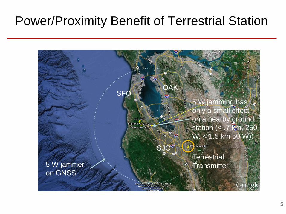
Power/Proximity Benefit of Terrestrial Station
5
5 W jammer
on GNSS
SFO OAK
SJC
5 W jamming has
only a small effect
on a nearby ground
station (< .7 km, 250
W, < 1.5 km 50 W))
Terrestrial
Transmitter
Current US APNT Program Plans
• Distance measuring equipment (DME) has long
been the primary source of navigation for most
commercial aviation
• DME is near- to mid-term APNT
– Multiple DME (DME/DME) positioning
• Long-term APNT is “going to concept”
– Refine requirements & concept development
– Target implementation in 2025
6
Outline: The Road to Future APNT
• 1. DME/DME & Future APNT
• 2. Enhanced DME (out of band) pseudolites
– 2A. Pulse Pair Position Modulation (PPPM)
– 2B. Carrier Phase
• 3. Improving Coverage: Ranging from other
terrestrial aviation signals (Automatic Dependent
Surveillance Broadcast (ADS-B), L-band Digital
Aeronautical Communication System (LDACS)
• 4. Multipath Mitigation 7
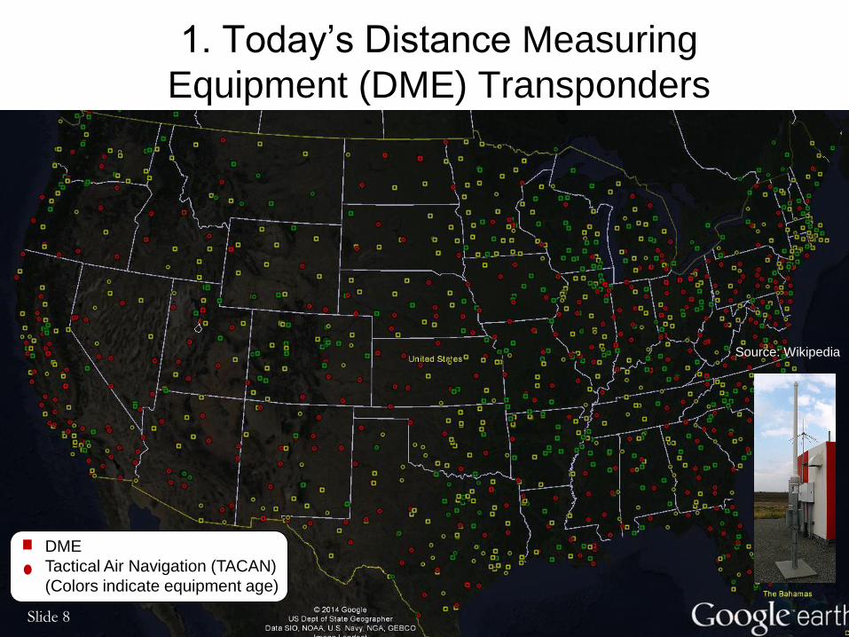
1. Today’s Distance Measuring
Equipment (DME) Transponders
8 Slide 8
Source: Wikipedia
DME
Tactical Air Navigation (TACAN)
(Colors indicate equipment age)
NextGen Near-Term DME/DME
• Current US DME system has coverage holes at
altitude (18000 ft & 24000 ft) when using
multiple DME (DME/DME) for RNAV 1.0
– Area Navigation (RNAV) of 1.0 nautical mile
– Need inertial reference unit (IRU)
• FAA NextGen examining the number of new
transponders needed to provide serve RNAV 1.0
enroute with DME/DME and some major
terminal area
9
Long-Term APNT to Improve APNT Capabilities
• Increased performance: terminal area &
approach operations (accuracy, coverage,
capacity, etc.)
• Increased resilience & robustness: signal
diversity, redundancy, authentication
• Additional services: data capacity
10
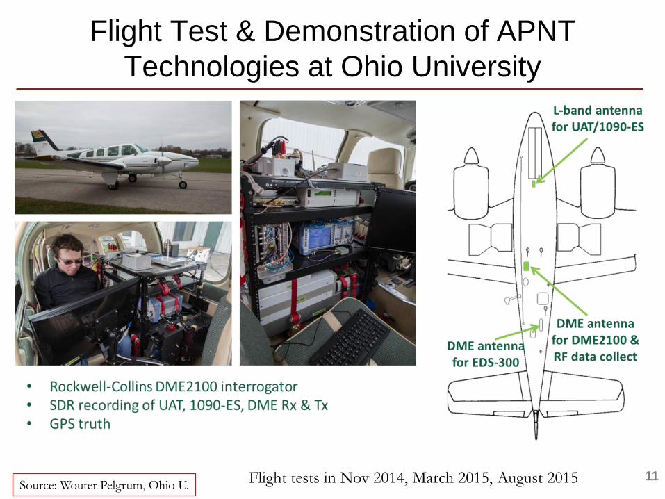
Flight Test & Demonstration of APNT
Technologies at Ohio University
Source: Wouter Pelgrum, Ohio U. Flight tests in Nov 2014, March 2015, August 2015 11
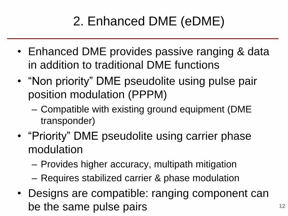
2. Enhanced DME (eDME)
• Enhanced DME provides passive ranging & data
in addition to traditional DME functions
• “Non priority” DME pseudolite using pulse pair
position modulation (PPPM)
– Compatible with existing ground equipment (DME
transponder)
• “Priority” DME pseudolite using carrier phase
modulation
– Provides higher accuracy, multipath mitigation
– Requires stabilized carrier & phase modulation
• Designs are compatible: ranging component can
be the same pulse pairs 12
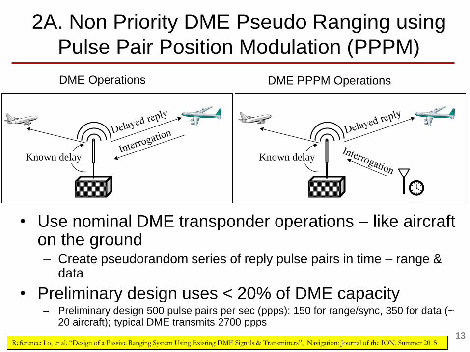
2A. Non Priority DME Pseudo Ranging using
Pulse Pair Position Modulation (PPPM)
• Use nominal DME transponder operations – like aircraft on the ground – Create pseudorandom series of reply pulse pairs in time – range &
data
• Preliminary design uses < 20% of DME capacity – Preliminary design 500 pulse pairs per sec (ppps): 150 for range/sync, 350 for data (~
20 aircraft); typical DME transmits 2700 ppps
DME Operations DME PPPM Operations
Known delay Known delay
Reference: Lo, et al. “Design of a Passive Ranging System Using Existing DME Signals & Transmitters”, Navigation: Journal of the ION, Summer 2015 13
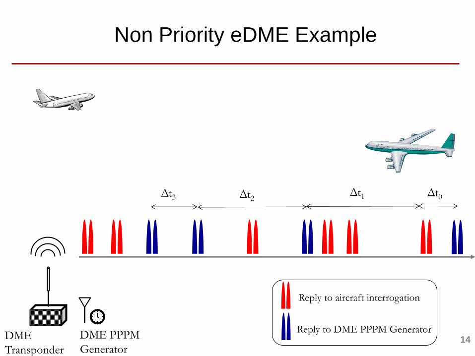
Non Priority eDME Example
Δt3 Δt2 Δt1 Δt0
Reply to aircraft interrogation
Reply to DME PPPM Generator 14 DME PPPM
Generator
DME
Transponder
USRP
30dB
Attenuator
Isolator
Directional
Coupler
30dB
GPS steered Clock
10 MHz & PPS
DME/TACAN
MM7000
Computer
Playback
Signal
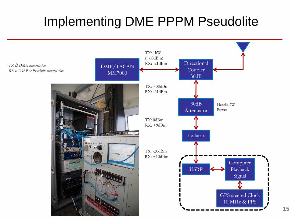
Implementing DME PPPM Pseudolite
TX: +30dBm
RX: -21dBm
TX: 1kW
(+60dBm)
RX: -21dBm
TX: 0dBm
RX: +9dBm
TX: -20dBm
RX: +10dBm
Handle 2W
Power
TX is DME transmission,
RX is USRP or Pseudolite transmission
15
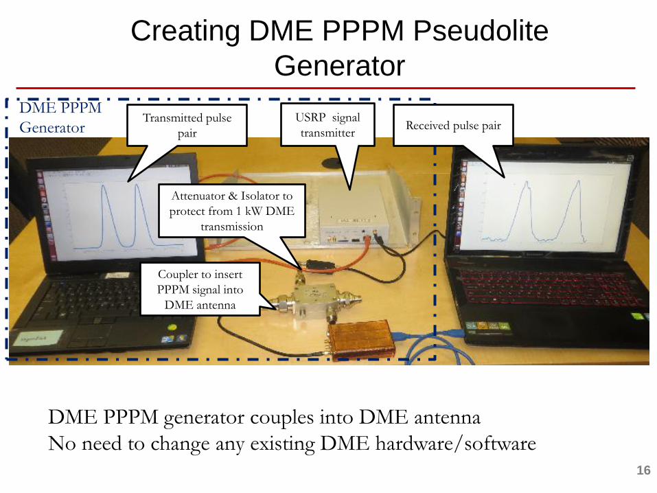
Creating DME PPPM Pseudolite
Generator
DME PPPM generator couples into DME antenna
No need to change any existing DME hardware/software
Transmitted pulse
pair
Attenuator & Isolator to
protect from 1 kW DME
transmission
Coupler to insert
PPPM signal into
DME antenna
USRP signal
transmitter Received pulse pair
DME PPPM
Generator
16
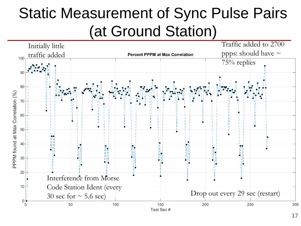
Static Measurement of Sync Pulse Pairs
(at Ground Station)
Interference from Morse
Code Station Ident (every
30 sec for ~ 5.6 sec)
Traffic added to 2700
ppps: should have ~
75% replies
Initially little
traffic added
Drop out every 29 sec (restart)
17
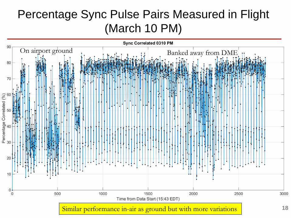
Percentage Sync Pulse Pairs Measured in Flight
(March 10 PM)
On airport ground Banked away from DME
Similar performance in-air as ground but with more variations 18
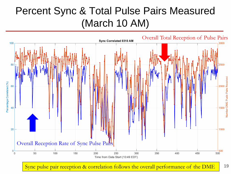
Percent Sync & Total Pulse Pairs Measured
(March 10 AM)
Sync pulse pair reception & correlation follows the overall performance of the DME
Overall Total Reception of Pulse Pairs
Overall Reception Rate of Sync Pulse Pairs
19
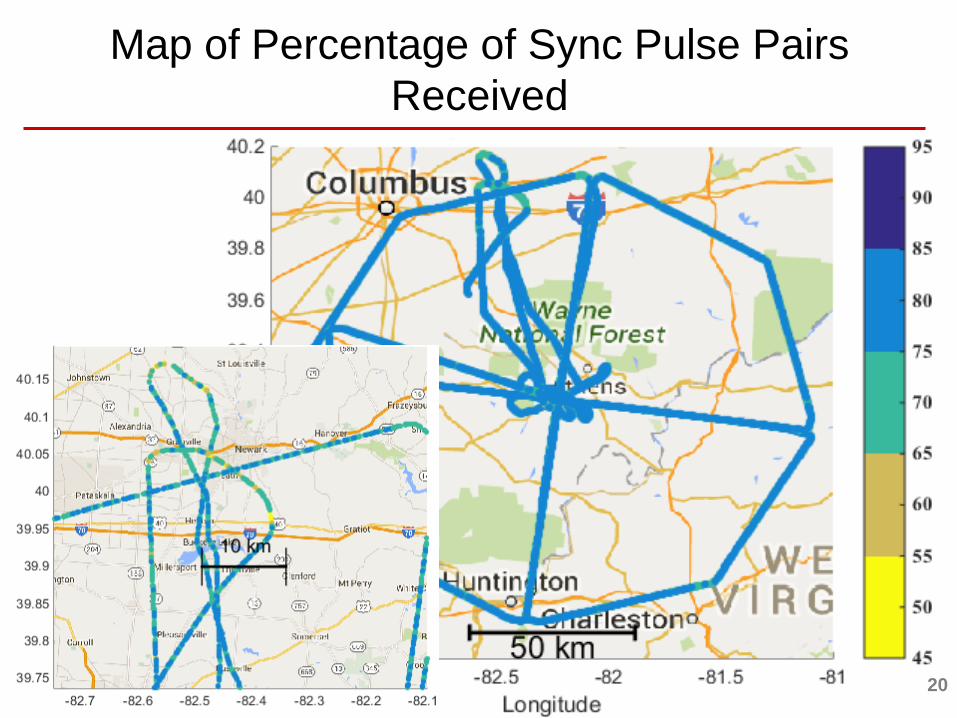
Map of Percentage of Sync Pulse Pairs
Received
20
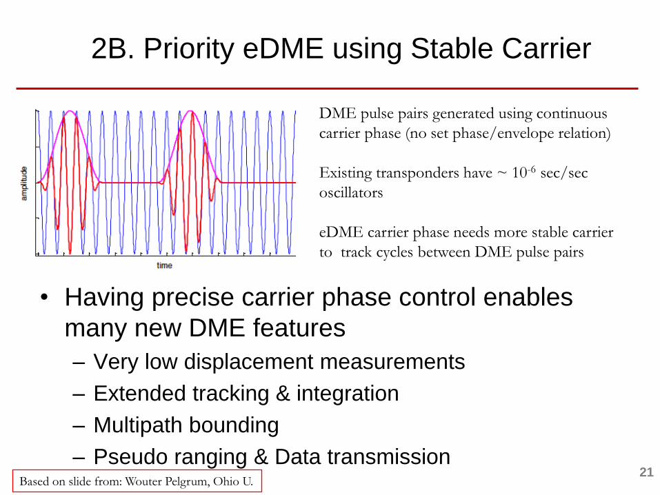
2B. Priority eDME using Stable Carrier
• Having precise carrier phase control enables
many new DME features
– Very low displacement measurements
– Extended tracking & integration
– Multipath bounding
– Pseudo ranging & Data transmission
DME pulse pairs generated using continuous
carrier phase (no set phase/envelope relation)
Existing transponders have ~ 10-6 sec/sec
oscillators
eDME carrier phase needs more stable carrier
to track cycles between DME pulse pairs
Based on slide from: Wouter Pelgrum, Ohio U. 21
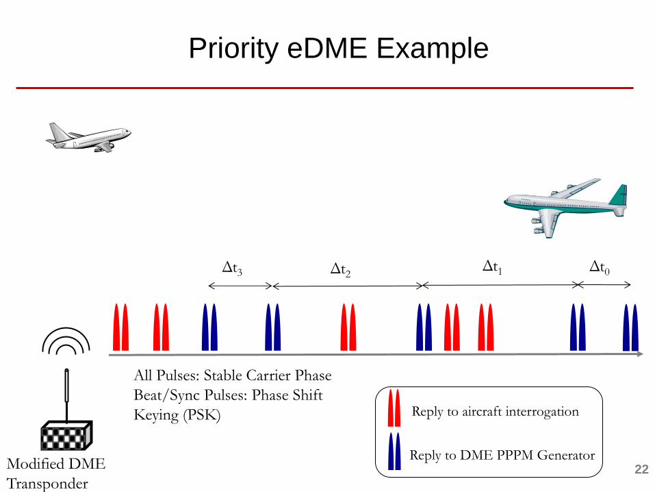
Priority eDME Example
All Pulses: Stable Carrier Phase
Beat/Sync Pulses: Phase Shift
Keying (PSK)
Δt3 Δt2 Δt1 Δt0
Reply to aircraft interrogation
Reply to DME PPPM Generator 22 Modified DME
Transponder
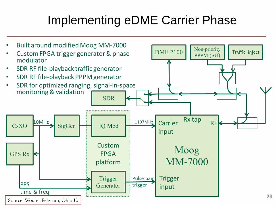
Implementing eDME Carrier Phase
Source: Wouter Pelgrum, Ohio U. 23
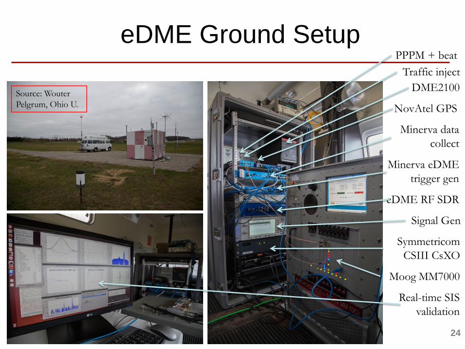
eDME Ground Setup
DME2100
Moog MM7000
Symmetricom
CSIII CsXO
eDME RF SDR
Minerva eDME
trigger gen
Minerva data
collect
Real-time SIS
validation
Signal Gen
NovAtel GPS
PPPM + beat
Traffic inject
Source: Wouter
Pelgrum, Ohio U.
24
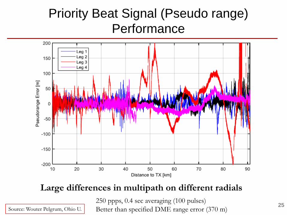
Priority Beat Signal (Pseudo range)
Performance
250 ppps, 0.4 sec averaging (100 pulses)
Better than specified DME range error (370 m) Source: Wouter Pelgrum, Ohio U.
Large differences in multipath on different radials
25
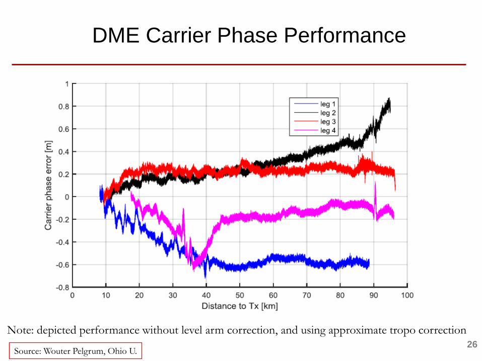
DME Carrier Phase Performance
Note: depicted performance without level arm correction, and using approximate tropo correction
Source: Wouter Pelgrum, Ohio U. 26
3. Ranging Using Other Terrestrial Aviation
Signals
• Two challenges with terrestrial signals for aviation
navigation are: low altitude coverage & multipath
• Using other signals to address these challenges
• Signals being studied
– Automatic Dependent Surveillance Broadcast (ADS-B):
1090 MHz Mode S Extended Squitter (ES), Universal
Access Transceiver (UAT)
– L-band Digital Aeronautical Communication System
(LDACS)
27
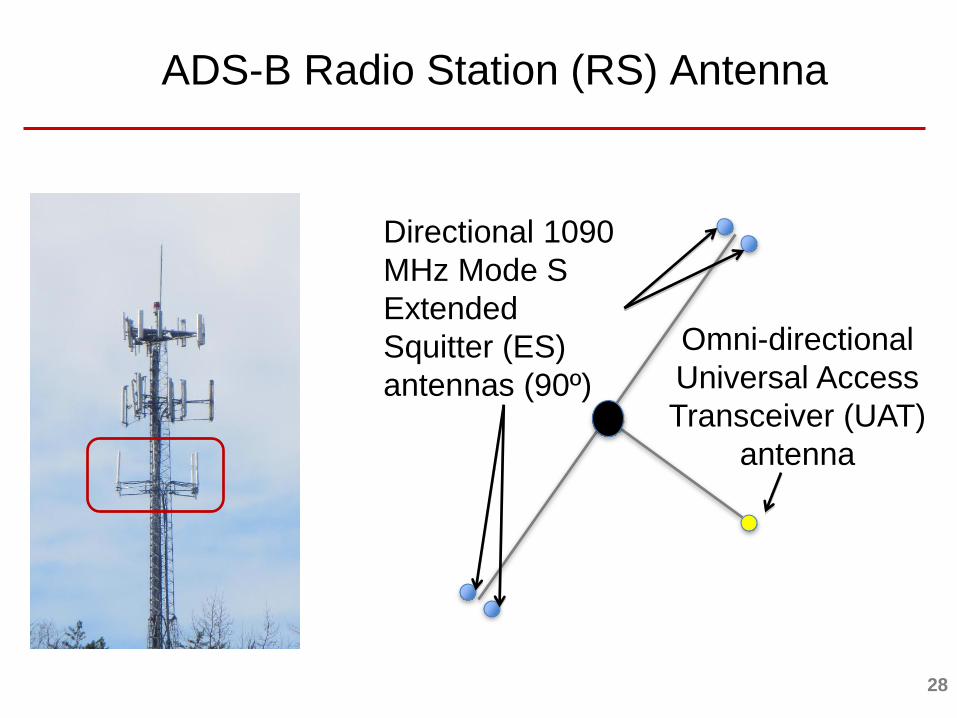
ADS-B Radio Station (RS) Antenna
Directional 1090
MHz Mode S
Extended
Squitter (ES)
antennas (90º)
Omni-directional
Universal Access
Transceiver (UAT)
antenna
28
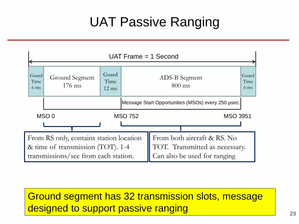
UAT Passive Ranging
ADS-B Segment
800 ms
Ground Segment
176 ms
Guard
Time
6 ms
Guard
Time
6 ms
UAT Frame = 1 Second
Message Start Opportunities (MSOs) every 250 μsec
MSO 0 MSO 752 MSO 3951
Guard
Time
12 ms
From RS only, contains station location
& time of transmission (TOT). 1-4
transmissions/sec from each station.
Ground segment has 32 transmission slots, message
designed to support passive ranging
From both aircraft & RS. No
TOT. Transmitted as necessary.
Can also be used for ranging
29
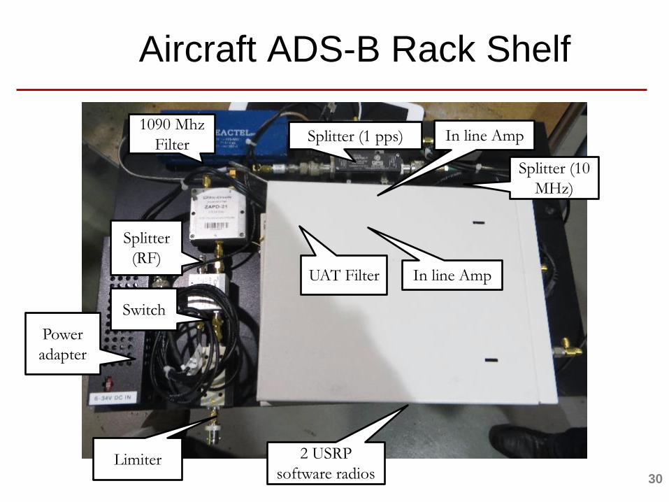
Aircraft ADS-B Rack Shelf
1090 Mhz
Filter In line Amp
In line Amp UAT Filter
Power
adapter
Splitter
(RF)
Splitter (10
MHz)
Splitter (1 pps)
Limiter
Switch
2 USRP
software radios 30
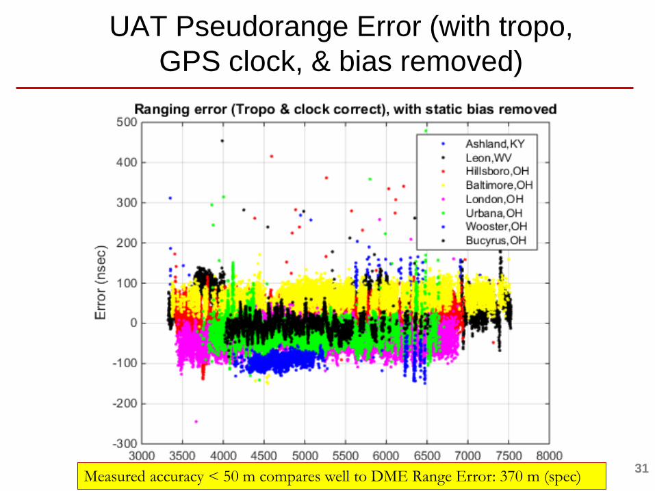
UAT Pseudorange Error (with tropo,
GPS clock, & bias removed)
Measured accuracy < 50 m compares well to DME Range Error: 370 m (spec) 31
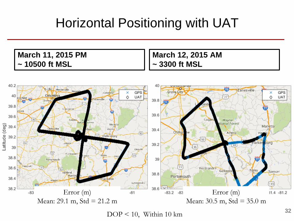
Horizontal Positioning with UAT
March 11, 2015 PM
~ 10500 ft MSL
March 12, 2015 AM
~ 3300 ft MSL
Error (m)
Mean: 29.1 m, Std = 21.2 m
Error (m)
Mean: 30.5 m, Std = 35.0 m
DOP < 10, Within 10 km 32
4. Multipath Assessment
• Multipath Effects – where do we have bad
multipath errors & why
• Multipath Characterization – what is the source
of the multipath
• Multipath Mitigation Strategies – what are
reasonable ways of reducing or alerting for
multipath
33
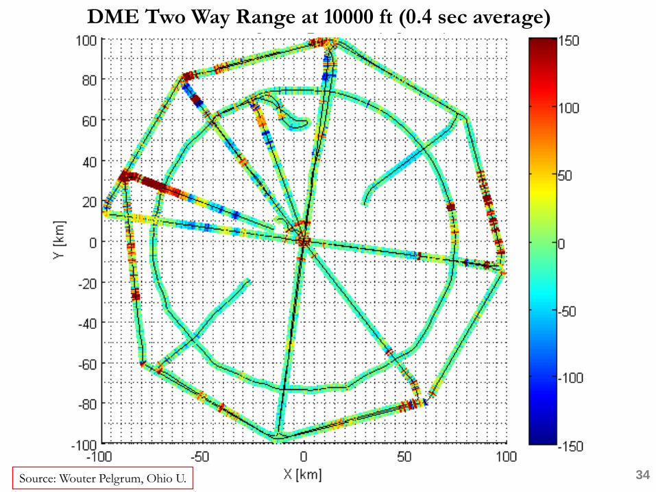
34 Source: Wouter Pelgrum, Ohio U.
DME Two Way Range at 10000 ft (0.4 sec average)
34
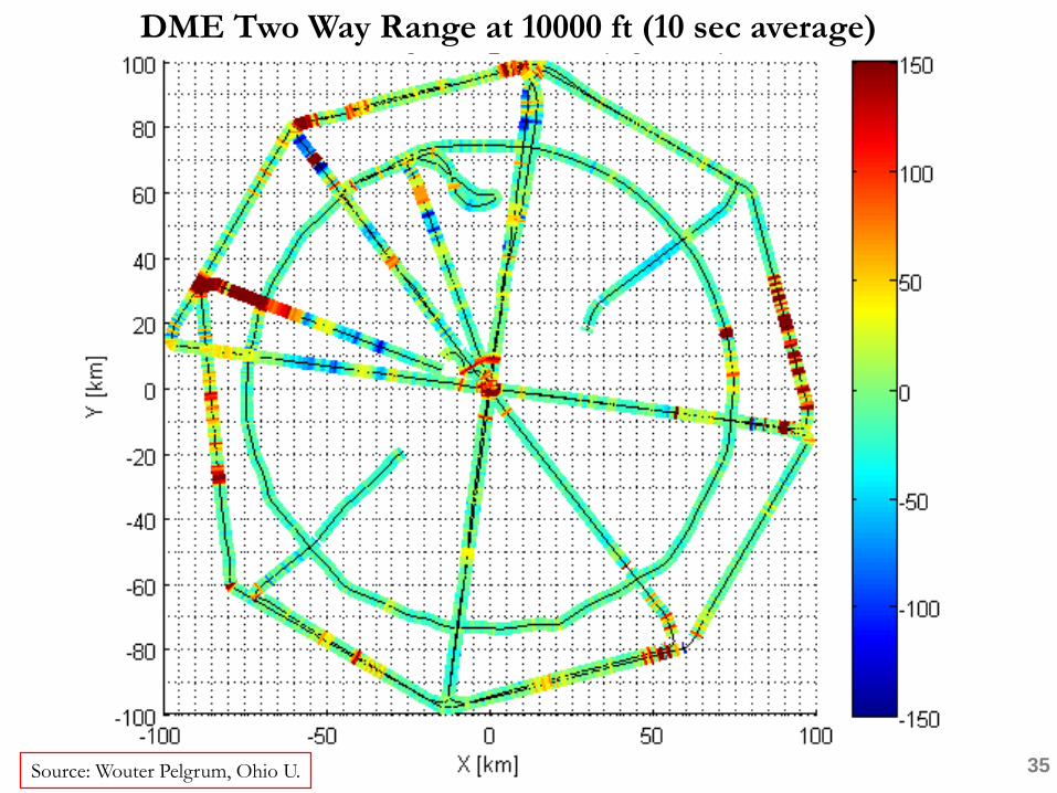
35 Source: Wouter Pelgrum, Ohio U.
DME Two Way Range at 10000 ft (10 sec average)
35
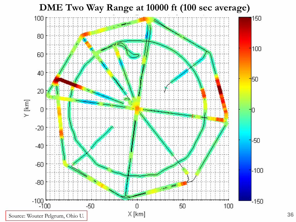
36 Source: Wouter Pelgrum, Ohio U.
DME Two Way Range at 10000 ft (100 sec average)
36
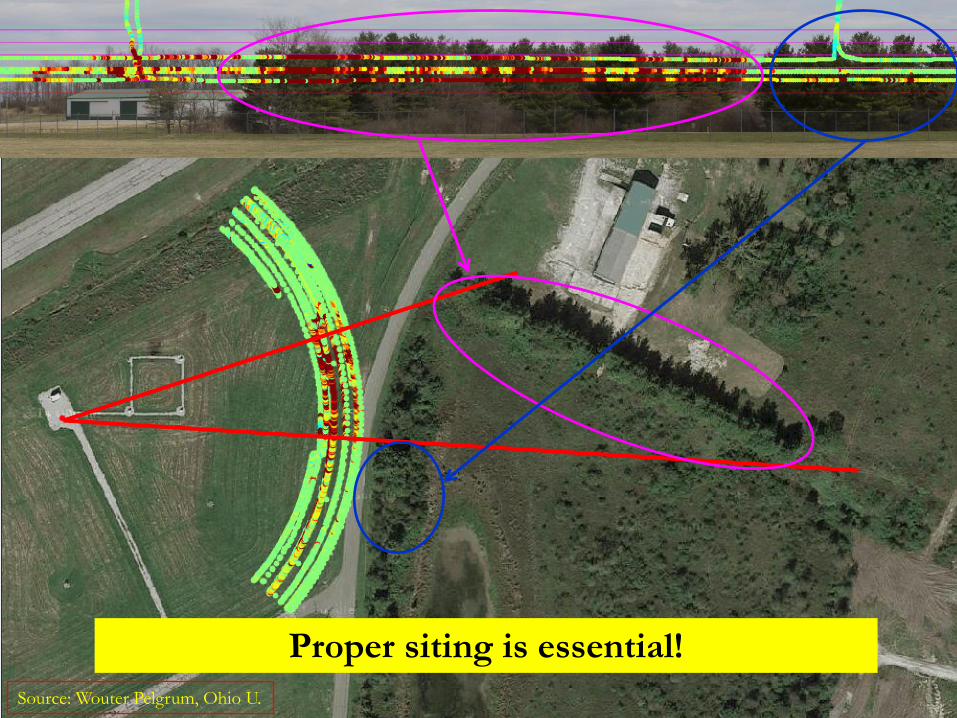
Proper siting is essential!
Source: Wouter Pelgrum, Ohio U.
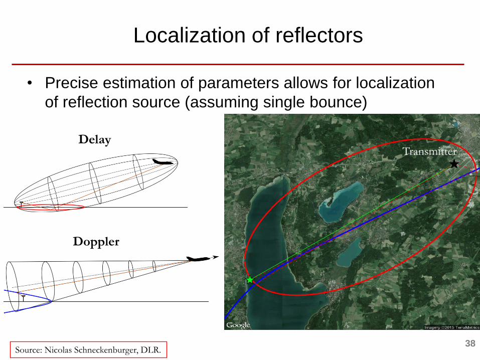
Localization of reflectors
Doppler
Delay
• Precise estimation of parameters allows for localization
of reflection source (assuming single bounce)
Source: Nicolas Schneckenburger, DLR.
Transmitter
38
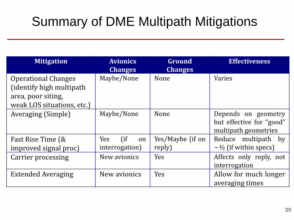
Summary of DME Multipath Mitigations
Mitigation Avionics Changes
Ground Changes
Effectiveness
Operational Changes (identify high multipath area, poor siting, weak LOS situations, etc.)
Maybe/None None Varies
Averaging (Simple) Maybe/None None Depends on geometry but effective for “good” multipath geometries
Fast Rise Time (& improved signal proc)
Yes (if on interrogation)
Yes/Maybe (if on reply)
Reduce multipath by ~½ (if within specs)
Carrier processing New avionics Yes Affects only reply, not interrogation
Extended Averaging
New avionics Yes Allow for much longer averaging times
39
Summary
• Terrestrial system are attractive from a resilience to interference – Comes with challenges: multipath, line of sight
• eDME concepts have been prototyped & tested – eDME PPPM compatible with existing equipment
– eDME carrier phase provides increase performance
• Several attractive L-band aviation signals may be used for APNT and are being tested (UAT, 1090 MHz Mode S ES, LDACS)
• Key challenges are being addressed in our testing
40
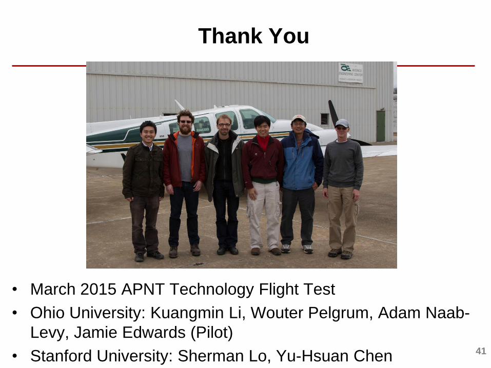
Thank You
• March 2015 APNT Technology Flight Test
• Ohio University: Kuangmin Li, Wouter Pelgrum, Adam Naab-
Levy, Jamie Edwards (Pilot)
• Stanford University: Sherman Lo, Yu-Hsuan Chen 41

Acknowledgements & Disclaimer
• The authors gratefully acknowledge the support of the FAA. We also appreciate the feedback and inputs of the members of the APNT technical team.
• Stanford: Yu Hsuan Chen
• Ohio University: Wouter Pelgrum, Kuangmin Li, Adam Naab-
Levy, Jamie Edwards
• DLR: Nicolas Schneckenburger
• FAA/Contractor: Mitch Narins, Robert Lilley, Robert Erikson
• Moog: George Weida, Achim Soelter
• The views expressed herein are those of the authors and are not to be construed as official or any other person or organization.
42