Embed Size (px)
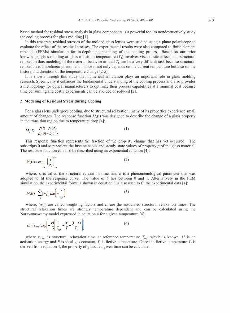
Citation preview
Procedia Engineering 19 ( 2011 ) 402 – 406
1877-7058 © 2011 Published by Elsevier Ltd.doi: 10.1016/j.proeng.2011.11.132
Available online at www.sciencedirect.com
1st CIRP Conference on Surface Integrity (CSI)
Residual stresses in glass after molding and its influence on optical properties
A. Y. Yia
aDepartment of Integrated Systems Engineering, The Ohio State University, 210 Baker Systems, 1971 Neal Ave, Columbus, OH 43210, USA
*, B. Taoa, F. Klockeb, O. Dambonb, F. Wangb
bFraunhofer Institute for Production Technology, Steinbachstr 17, 54004 Aachen, Germany
Abstract
Compression molding of glass optics is gradually becoming a viable manufacturing process for high precision optical lenses. However, during cooling, glass properties undergo a small amount of changes due to structural relaxation. As a result, residual stresses are trapped inside the molded glass lenses. In this research, compression molded lenses were studied using the birefringence method assisted by the finite element analysis. The experimental and simulation results showed that compression molding process can be controlled to a very high precision providing that the proper cooling is applied during cooling. In addition, numerical analysis using finite element analysis also provides a better understand of the cooling process and offers an economic solution for process optimization for low cost glass lens production. © 2012 Published by Elsevier Ltd. Selection and peer-review under responsibility of Prof. E. Brinksmeier Keywords: Glass; Residual Stress, Finite Element Method (FEM), Optical
1. Residual Stress in Precision Lens by Compression Glass Molding
Residual stresses are important criteria for evaluating molded glass optical components. Residual stresses inside the glass lenses contribute to refractive index variation, result in unwanted light path as well as intensity variation that will lead to image quality deterioration. Different methods have been tested to measure residual stress distribution inside a glass workpiece. Among these techniques, photoelasticity
* Corresponding author. Tel.: +1 614-292-9984; fax: +1 614-292-7852. E-mail address: [email protected]
403 A.Y. Yi et al. / Procedia Engineering 19 ( 2011 ) 402 – 406
based method for residual stress analysis in glass components is a powerful tool to nondestructively study the cooling process for glass molding [1].
In this research, residual stresses of the molded glass lenses were studied using a plane polariscope to evaluate the effect of the residual stresses. The experimental results were also compared to finite element methods (FEMs) simulation for in-depth understanding of the cooling process. Based on our prior knowledge, glass molding at glass transition temperature (Tg) involves viscoelastic effects and structural relaxation thus modeling of the material behavior around Tg can be a very difficult task because structural relaxation is a nonlinear phenomenon since it not only depends on the current temperature but also on the history and direction of the temperature change [2-5].
It is shown through this study that numerical simulation plays an important role in glass molding research. Specifically it enhances the fundamental understanding of the cooling process and also provides a methodology for optical manufacturers to optimize their process capabilities at a minimal cost because time consuming and costly experiments can be avoided or reduced [2].
2. Modeling of Residual Stress during Cooling
For a glass lens undergoes cooling, due to structural relaxation, many of its properties experience small amount of changes. The response function Mv(t) was designed to describe the change of a glass property in the transition region due to temperature drop [4]:
(1)
This response function represents the fraction of the property change that has yet occurred. The subscripts 0 and represent the instantaneous and steady state values of property p of the glass material. The response function can also be described using an exponential function [4]:
(2)
where, v is called the structural relaxation time, and b is a phenomenological parameter that was adopted to fit the response curve. The value of b lies between 0 and 1. Alternatively in the FEM simulation, the experimental formula shown in equation 3 is also used to fit the experimental data [4]:
(3)
where, (wg)i are called weighting factors and vi are the associated structural relaxation times. The structural relaxation times are strongly temperature dependent and can be calculated using the Narayanaswamy model expressed in equation 4 for a given temperature [4]:
(4)
where v ref is structural relaxation time at reference temperature Tref, which is known. H is an activation energy and R is ideal gas constant. Tf is fictive temperature. Once the fictive temperature Tf is derived from equation 4, the property of glass at a given time can be calculated.
404 A.Y. Yi et al. / Procedia Engineering 19 ( 2011 ) 402 – 406
3. Residual Stress Measurement and Analysis
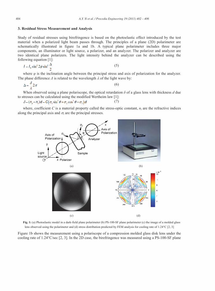
Study of residual stresses using birefringence is based on the photoelastic effect introduced by the test material when a polarized light beam passes through. The principles of a plane (2D) polarimeter are schematically illustrated in figure 1a and 1b. A typical plane polarimeter includes three major components, an illuminator or light source, a polarizer, and an analyzer. The polarizer and analyzer are two identical plane polarizers. The light intensity behind the analyzer can be described using the following equation [1]:
(5)
where is the inclination angle between the principal stress and axis of polarization for the analyzer. The phase difference is related to the wavelength of the light wave by:
(6)
When observed using a plane polariscope, the optical retardation of a glass lens with thickness d due to stresses can be calculated using the modified Wertheim law [1]:
(7)
where, coefficient C is a material property called the stress-optic constant, ni are the refractive indices along the principal axis and i are the principal stresses.
(a) (b)
(c) (d)
Fig. 1: (a) Photoelastic model in a dark-field plane polarimeter (b) PS-100-SF plane polarimeter (c) the image of a molded glass lens observed using the polarimeter and (d) stress distribution predicted by FEM analysis for cooling rate of 1.24°C [2, 3]
Figure 1b shows the measurement using a polariscope of a compression molded glass disk lens under the cooling rate of 1.24°C/sec [2, 3]. In the 2D case, the birefringence was measured using a PS-100-SF plane
405 A.Y. Yi et al. / Procedia Engineering 19 ( 2011 ) 402 – 406
polarimeter (Strainoptics Inc. North Wales, Pennsylvania). To calculate the total effect on residual stresses by the entire thickness of the glass lens in the x direction based on the theory of glass structural relaxation, retardation of each individual thin layer was calculated and then integrated over the thickness direction. Figure 1c shows the intensity distribution using numerical simulation method (performed using FEM software MSC Marc). The FEM results were based on the monochromatic light of 565 nm wavelength [2, 3]. The dark area on the plate where the directions of the principal stresses are parallel to the axes of the polaroid is the isoclinic. Furthermore,The intensity change along the radius is caused by the relative optical retardation, known as isochromatics. Pseudo colors were used to show light intensity. The results from numerical simulation and experiments showed a very good agreement at cooling rate of 1.24°C/sec [2, 3]. Similar results were also verified for cooling under different conditions [2, 3].
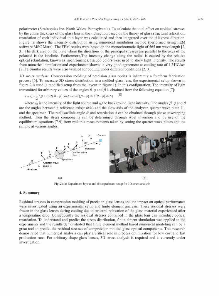
3D stress analysis: Compression molding of precision glass optics is inherently a freeform fabrication process [6]. To measure 3D stress distribution in a molded glass lens, the experimental setup shown in figure 2 is used (a modified setup from the layout in figure 1). In this configuration, The intensity of light transmitted for arbitrary values of the angles , and is obtained from the following equation [7]:
01 [1 2 2 2 ]2bI I I sin cos cos sin sin (8)
where I0 is the intensity of the light source and Ib the background light intensity. The angles , and are the angles between a reference axis(x axis) and the slow axis of the analyzer, quarter wave plate , and the specimen. The real isoclinic angle and retardation can be obtained through phase unwrapping method. Then the stress components can be determined through Abel inversion and by use of the equilibrium equations [7-9] from multiple measurements taken by setting the quarter wave plates and the sample at various angles.
(a) (b)
Fig. 2: (a) Experiment layout and (b) experiment setup for 3D stress analysis
4. Summary
Residual stresses in compression molding of precision glass lenses and the impact on optical performance were investigated using an experimental setup and finite element analysis. These residual stresses were frozen in the glass lenses during cooling due to structral relaxation of the glass material experienced after a temperature drop. Consequently the residual stresses contained in the glass lens can introduce optical retardation. To understand and predict the stress distribution, finite elment simulation was applied to the experiments and the results demonstrated that finite element method based numerical modeling can be a great tool to predict the residual stresses of compression molded glass optical components. This research demostrated that numerical analysis can play a critical role in process optimization for low cost and fast production runs. For arbitrary shape glass lenses, 3D stress analysis is required and is currently under investigation.
406 A.Y. Yi et al. / Procedia Engineering 19 ( 2011 ) 402 – 406
Acknowledgements
This material is partially based on work supported by National Science Foundation under Grant No. CMMI 0547311. Any opinions, findings, and conclusions or recommendations expressed in this material are those of the authors and do not necessarily reflect the views of the National Science Foundation. The authors also acknowledge the financial support by the German Research Foundation within the SFB/TR4 “Process Chains for the Replication of Complex Optical Elements.”
References
[1] A. Kuske, G. Robertson, Photoelastic Stress Analysis, Wiley, London (1974). [2] Y. Chen, “Thermal forming process for precision freeform optical mirrors and micro glass optics,” The Ohio State
University, Ph.D. Dissertation, (2010). [3] Y. Chen, L. Su, A. Y. Yi, F. Klocke, G. Pongs, “Numerical simulation and experimental study of residual stresses in
compression molding of precision glass optical components,” ASME J Manuf Sci Eng, 130, 051012-1-9 (2008). [4] T. F. Soules, R. F. Busbey, S. M. Rekhson, A. Markovsky, M. A. Burke, “Finite element calculation of stresses in glass
parts undergoing viscous relaxation,” J Am Ceram Soc, 70 (2) , 90–95 (1983). [5] O. S. Narayanaswamy, “A model of structural relaxation in glass,” J Am Ceram Soc, 54 (10), 491-498 (1971). [6] A. Y. Yi, C. N. Huang, F. Klocke, C. Brecher, M. Winterschladen, G. Pongs, “Development of a compression molding
process for three-dimensional tailored free-form glass optics,” App Opt, 45 (25), 6511-8, 1 September (2006). [7] A Ajovalasit, S Barone, G Petrucci, “A method for reducing the influence of quarter-wave plate errors in phase stepping
photoelasticity,” J Strain Anal Eng, 33 (3) 207 -216, January 1 (1998). [8] H. Aben, A. Errapart, “A non-linear algorithm of photoelastic tomography for the axisymmetric problem,” Exp Mech, 47
(6), 821–830 (2007). [9] M. Ramji, E. Nithila, K. Devvrath, K. Ramesh, “Assessment of autonomous phase unwrapping of isochromatic phase
maps in digital photoelasticity,” Sadhana, 33 (1), 27-44 (2008).

![Prediction of welding residual stresses using machine ... · characterise the distribution of residual stresses in structural welds [6, 7]. With the development of residual stress](https://img.pdfslide.us/doc/110x75/5fa3f63f3be93a3412525cc3/prediction-of-welding-residual-stresses-using-machine-characterise-the-distribution.jpg)