Embed Size (px)
Citation preview
Residual Stress and Plastic Anisotropy in Indented 2024-T351 Aluminum Disks
Bjørn Clausen*
Recent studies have proven that generating a well defined residual stress state using the indented disk approach is an excellent way to validate experimental and modeling techniques for measuring and predicting residual stresses [
, Michael B. Prime, Saurabh Kabra, and Donald W. Brown; Los Alamos National Laboratory, USA
Pierluigi Pagliaro, University of Palermo, Italy
Peter Backlund and Sanjiv Shah; University of Texas, USA
Everett Criss; University of California, San Diego, USA
ABSTRACT
1,2]. The previous studies dealt with indented stainless steel disks, and included experimental determination of residual stresses using the Contour Method [3,4] and neutron diffraction measurements [5,6
Residual stresses, i.e. short range stresses that average out to zero in an unloaded sample [
]. The measured residual stress states showed good agreement between the techniques, and a Finite Element Model predicted residual stress state based upon material properties determined form standard tension and compression/tension tests was also in good agreement with the measurements. In the present work, disks of 2024-T351 Aluminum were investigated. As before, the residual stress profile was measured using neutron diffraction and the Contour Method and Finite Element Modeling was employed to predict the residual stress profile. Analysis and comparison of the three techniques were complicated by the fact that the experimental data shows evidence of plastic anisotropy and strong Bauschinger effect within the indented disks. INTRODUCTION
7], are present in most structures and components after manufacture. They originate in elastic, plastic and/or thermal anisotropies on the grain scale inherent to the material, combined with any applied mechanical and/or thermal processes applied during manufacture. The residual stresses can be either beneficial or detrimental depending on the failure mechanism and the sign of the residual stress, e.g. compressive residual stresses at the surface are beneficial when the failure mode is fatigue or stress corrosion cracking [8]. Many different techniques have been developed to measure residual stresses in components, some destructive and some non-destructive. Hole drilling [9], slitting [10 3] and contour [ ] are examples of destructive techniques. Most non-destructive techniques are based upon diffraction, with X-ray surface measurements [11] (depth profiles can be obtained with layer removal, but then it becomes destructive [12]) and bulk synchrotron X-ray [13,14] and neutron diffraction [15
A specimen that would be suitable for measuring residual stress with relaxation methods was desired in order to validate some theoretical developments for the contour method [
] measurement. In the present study we present measurements of residual stresses in indented disks using the contour method and neutron diffraction, combined with model predictions using finite element modeling. SPECIMEN AND MATERIAL
2]. Indented disks were used to provide a well-controlled residual stress state. Similar disks on 316L stainless steel gave a residual stress distribution where the FEM predictions agreed well with neutron diffraction and contour method measurement [1]. For this study, an aluminum 2024-T351 was chosen for the higher value of the ratio σy/E (≈ 4300 με), which indicates the possibility to have higher residual stresses relative to the elastic modulus. That will lead to a higher deformation on stress relaxation, which is a good advantage for the application of the contour method and hole-drilling method.
* Corresponding author: [email protected], P.O. Box 1663, MS H805, Los Alamos, NM 87545, USA.
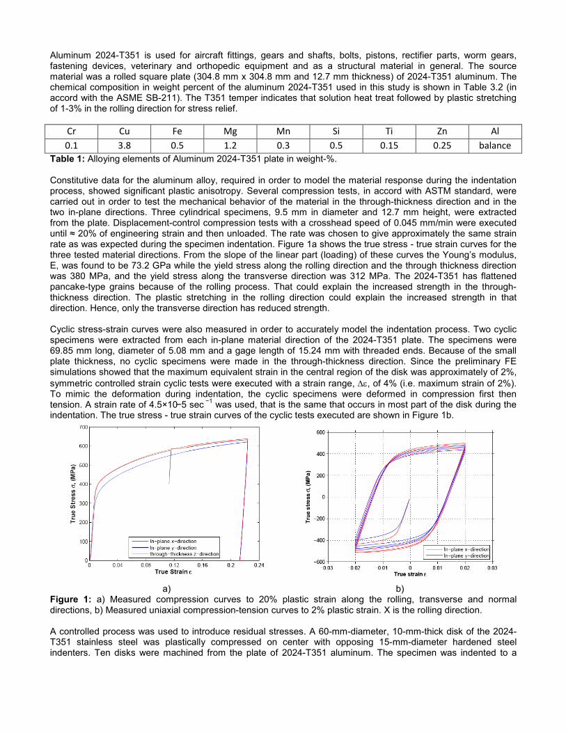
Aluminum 2024-T351 is used for aircraft fittings, gears and shafts, bolts, pistons, rectifier parts, worm gears, fastening devices, veterinary and orthopedic equipment and as a structural material in general. The source material was a rolled square plate (304.8 mm x 304.8 mm and 12.7 mm thickness) of 2024-T351 aluminum. The chemical composition in weight percent of the aluminum 2024-T351 used in this study is shown in Table 3.2 (in accord with the ASME SB-211). The T351 temper indicates that solution heat treat followed by plastic stretching of 1-3% in the rolling direction for stress relief.
Cr Cu Fe Mg Mn Si Ti Zn Al 0.1 3.8 0.5 1.2 0.3 0.5 0.15 0.25 balance
Table 1: Alloying elements of Aluminum 2024-T351 plate in weight-%. Constitutive data for the aluminum alloy, required in order to model the material response during the indentation process, showed significant plastic anisotropy. Several compression tests, in accord with ASTM standard, were carried out in order to test the mechanical behavior of the material in the through-thickness direction and in the two in-plane directions. Three cylindrical specimens, 9.5 mm in diameter and 12.7 mm height, were extracted from the plate. Displacement-control compression tests with a crosshead speed of 0.045 mm/min were executed until ≈ 20% of engineering strain and then unloaded. The rate was chosen to give approximately the same strain rate as was expected during the specimen indentation. Figure 1a shows the true stress - true strain curves for the three tested material directions. From the slope of the linear part (loading) of these curves the Young’s modulus, E, was found to be 73.2 GPa while the yield stress along the rolling direction and the through thickness direction was 380 MPa, and the yield stress along the transverse direction was 312 MPa. The 2024-T351 has flattened pancake-type grains because of the rolling process. That could explain the increased strength in the through-thickness direction. The plastic stretching in the rolling direction could explain the increased strength in that direction. Hence, only the transverse direction has reduced strength. Cyclic stress-strain curves were also measured in order to accurately model the indentation process. Two cyclic specimens were extracted from each in-plane material direction of the 2024-T351 plate. The specimens were 69.85 mm long, diameter of 5.08 mm and a gage length of 15.24 mm with threaded ends. Because of the small plate thickness, no cyclic specimens were made in the through-thickness direction. Since the preliminary FE simulations showed that the maximum equivalent strain in the central region of the disk was approximately of 2%, symmetric controlled strain cyclic tests were executed with a strain range, ∆ε, of 4% (i.e. maximum strain of 2%). To mimic the deformation during indentation, the cyclic specimens were deformed in compression first then tension. A strain rate of 4.5×10⁻⁵ sec −1 was used, that is the same that occurs in most part of the disk during the indentation. The true stress - true strain curves of the cyclic tests executed are shown in Figure 1b.
a) b) Figure 1: a) Measured compression curves to 20% plastic strain along the rolling, transverse and normal directions, b) Measured uniaxial compression-tension curves to 2% plastic strain. X is the rolling direction. A controlled process was used to introduce residual stresses. A 60-mm-diameter, 10-mm-thick disk of the 2024-T351 stainless steel was plastically compressed on center with opposing 15-mm-diameter hardened steel indenters. Ten disks were machined from the plate of 2024-T351 aluminum. The specimen was indented to a
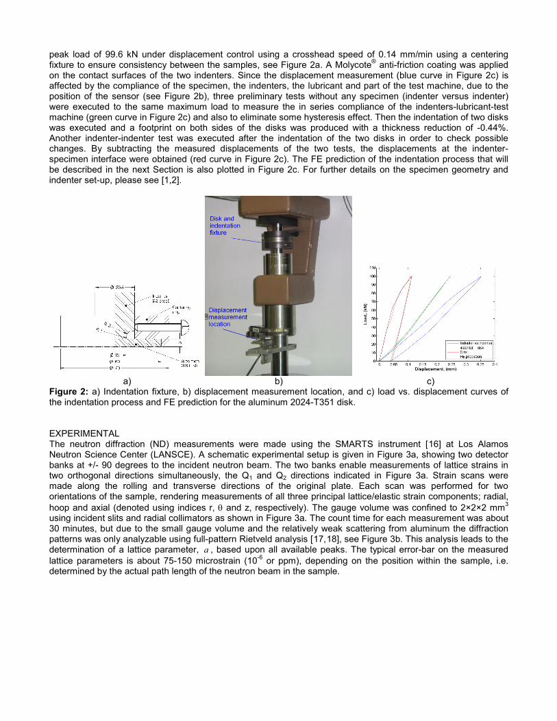
peak load of 99.6 kN under displacement control using a crosshead speed of 0.14 mm/min using a centering fixture to ensure consistency between the samples, see Figure 2a. A Molycote® anti-friction coating was applied on the contact surfaces of the two indenters. Since the displacement measurement (blue curve in Figure 2c) is affected by the compliance of the specimen, the indenters, the lubricant and part of the test machine, due to the position of the sensor (see Figure 2b), three preliminary tests without any specimen (indenter versus indenter) were executed to the same maximum load to measure the in series compliance of the indenters-lubricant-test machine (green curve in Figure 2c) and also to eliminate some hysteresis effect. Then the indentation of two disks was executed and a footprint on both sides of the disks was produced with a thickness reduction of -0.44%. Another indenter-indenter test was executed after the indentation of the two disks in order to check possible changes. By subtracting the measured displacements of the two tests, the displacements at the indenter-specimen interface were obtained (red curve in Figure 2c). The FE prediction of the indentation process that will be described in the next Section is also plotted in Figure 2c. For further details on the specimen geometry and indenter set-up, please see [1,2].
a) b) c) Figure 2: a) Indentation fixture, b) displacement measurement location, and c) load vs. displacement curves of the indentation process and FE prediction for the aluminum 2024-T351 disk. EXPERIMENTAL The neutron diffraction (ND) measurements were made using the SMARTS instrument [16
Figure 3] at Los Alamos
Neutron Science Center (LANSCE). A schematic experimental setup is given in a, showing two detector banks at +/- 90 degrees to the incident neutron beam. The two banks enable measurements of lattice strains in two orthogonal directions simultaneously, the Q1 and Q2 directions indicated in Figure 3a. Strain scans were made along the rolling and transverse directions of the original plate. Each scan was performed for two orientations of the sample, rendering measurements of all three principal lattice/elastic strain components; radial, hoop and axial (denoted using indices r, θ and z, respectively). The gauge volume was confined to 2×2×2 mm3 using incident slits and radial collimators as shown in Figure 3a. The count time for each measurement was about 30 minutes, but due to the small gauge volume and the relatively weak scattering from aluminum the diffraction patterns was only analyzable using full-pattern Rietveld analysis [17,18 Figure 3], see b. This analysis leads to the determination of a lattice parameter, a , based upon all available peaks. The typical error-bar on the measured lattice parameters is about 75-150 microstrain (10-6 or ppm), depending on the position within the sample, i.e. determined by the actual path length of the neutron beam in the sample.
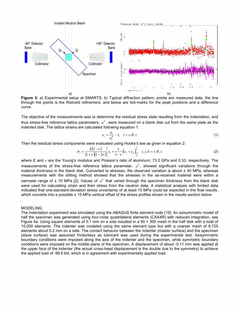
a) b) Figure 3: a) Experimental setup at SMARTS, b) Typical diffraction pattern; points are measured data, the line through the points is the Rietveld refinement, and below are tick-marks for the peak positions and a difference curve. The objective of the measurements was to determine the residual stress state resulting from the indentation, and thus stress-free reference lattice parameters, 0a , were measured on a blank disk cut from the same plate as the indented disk. The lattice strains are calculated following equation 1:
zriaa
i
ii ,,,10 θε =−= (1)
Then the residual stress components were evaluated using Hooke’s law as given in equation 2:
( )
( )( ) ( ) zrkjiEkjii ,,,,,
12111 θεε
ννε
νννσ =
+
−+
−+−
= (2)
where E and ν are the Young’s modulus and Poisson’s ratio of aluminum; 73.2 GPa and 0.33, respectively. The measurements of the stress-free reference lattice parameter, 0a , showed significant variations through the material thickness in the blank disk. Converted to stresses, the observed variation is about ± 40 MPa, whereas measurements with the slitting method showed that the stresses in the as-received material were within a narrower range of ± 10 MPa [2]. Values of 0a that varied through the specimen thickness from the blank disk were used for calculating strain and then stress from the neutron data. A statistical analysis with limited data indicated that one-standard-deviation stress uncertainty of at least 15 MPa could be expected in the final results, which converts into a possible ± 15 MPa vertical offset of the stress profiles shown in the results section below. MODELING The indentation experiment was simulated using the ABAQUS finite element code [19
Figure 4
]. An axisymmetric model of half the specimen was generated using four-node quadrilateral elements (CAX4R) with reduced integration, see
a. Using square elements of 0.1 mm on a side resulted in a 50 × 300 mesh in the half disk with a total of 15,000 elements. The indenter was modeled using the same element type but with a coarser mesh of 8,725 elements about 0.2 mm on a side. The contact behavior between the indenter (master surface) and the specimen (slave surface) was assumed frictionless as lubricant was used during the experimental test. Axisymmetric boundary conditions were imposed along the axis of the indenter and the specimen, while symmetric boundary conditions were imposed on the middle plane of the specimen. A displacement of about -0.11 mm was applied at the upper face of the indenter (the actual cross-head displacement is the double due to the symmetry) to achieve the applied load of -99.6 kN, which is in agreement with experimentally applied load.
Incident Neutron Beam
Q1 Q2
+90° Detector Bank
-90° Detector Bank
Specimen
Collimator Collimator
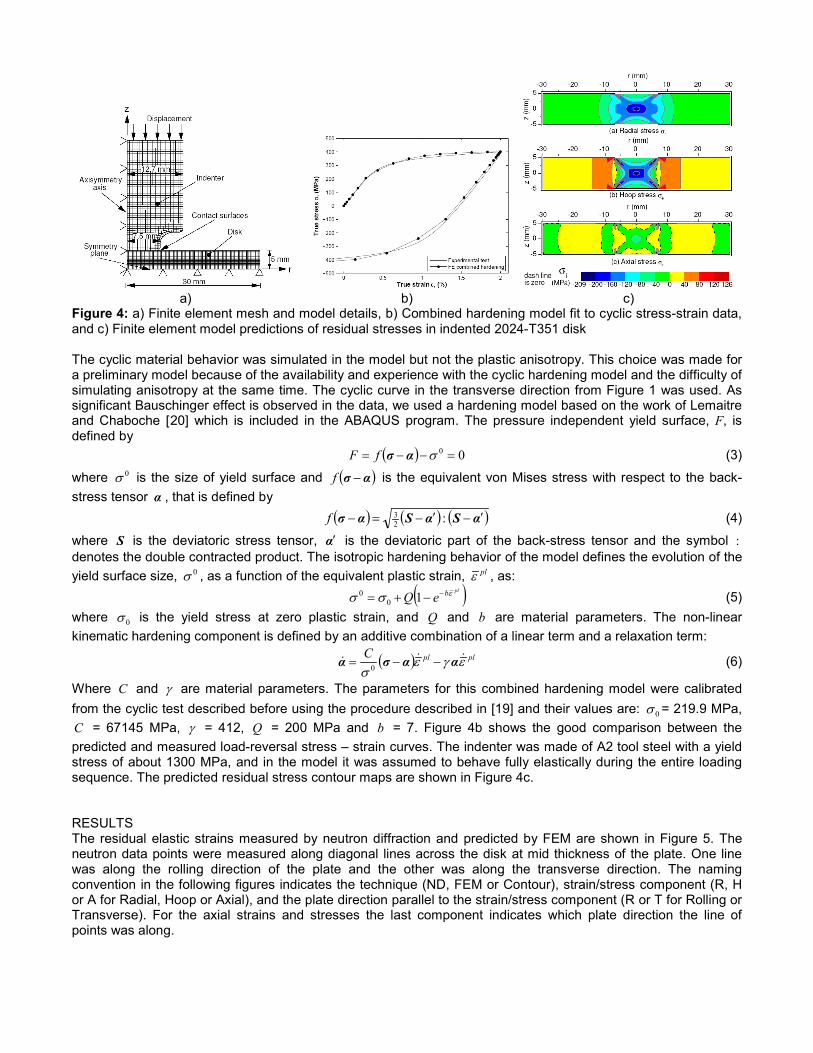
a) b) c) Figure 4: a) Finite element mesh and model details, b) Combined hardening model fit to cyclic stress-strain data, and c) Finite element model predictions of residual stresses in indented 2024-T351 disk The cyclic material behavior was simulated in the model but not the plastic anisotropy. This choice was made for a preliminary model because of the availability and experience with the cyclic hardening model and the difficulty of simulating anisotropy at the same time. The cyclic curve in the transverse direction from Figure 1 was used. As significant Bauschinger effect is observed in the data, we used a hardening model based on the work of Lemaitre and Chaboche [20
( ) 00 =−−= σασfF
] which is included in the ABAQUS program. The pressure independent yield surface, F, is defined by (3)
where 0σ is the size of yield surface and ( )ασ −f is the equivalent von Mises stress with respect to the back-stress tensor α , that is defined by ( ) ( ) ( )αSαSασ ′−′−=− :2
3f (4)
where S is the deviatoric stress tensor, α′ is the deviatoric part of the back-stress tensor and the symbol : denotes the double contracted product. The isotropic hardening behavior of the model defines the evolution of the yield surface size, 0σ , as a function of the equivalent plastic strain, plε , as: ( )plbeQ εσσ −−+= 10
0 (5) where 0σ is the yield stress at zero plastic strain, and Q and b are material parameters. The non-linear kinematic hardening component is defined by an additive combination of a linear term and a relaxation term:
( ) plplC εγεσ
αασα −−= 0 (6)
Where C and γ are material parameters. The parameters for this combined hardening model were calibrated from the cyclic test described before using the procedure described in [19] and their values are: 0σ = 219.9 MPa, C = 67145 MPa, γ = 412, Q = 200 MPa and b = 7. Figure 4b shows the good comparison between the predicted and measured load-reversal stress – strain curves. The indenter was made of A2 tool steel with a yield stress of about 1300 MPa, and in the model it was assumed to behave fully elastically during the entire loading sequence. The predicted residual stress contour maps are shown in Figure 4c. RESULTS The residual elastic strains measured by neutron diffraction and predicted by FEM are shown in Figure 5. The neutron data points were measured along diagonal lines across the disk at mid thickness of the plate. One line was along the rolling direction of the plate and the other was along the transverse direction. The naming convention in the following figures indicates the technique (ND, FEM or Contour), strain/stress component (R, H or A for Radial, Hoop or Axial), and the plate direction parallel to the strain/stress component (R or T for Rolling or Transverse). For the axial strains and stresses the last component indicates which plate direction the line of points was along.
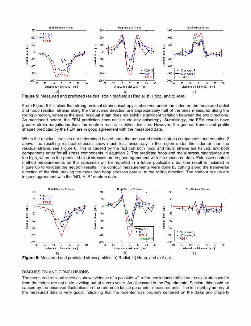
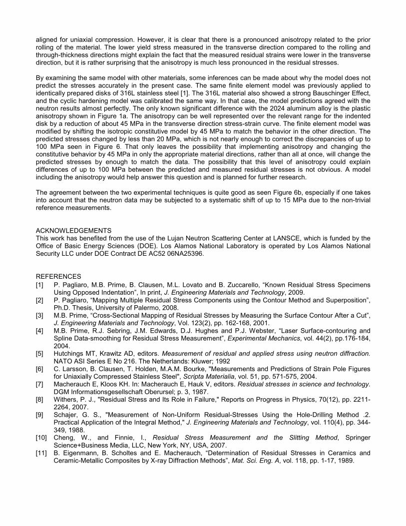
a) b) c) Figure 5: Measured and predicted residual strain profiles; a) Radial, b) Hoop, and c) Axial. From Figure 5 it is clear that strong residual strain anisotropy is observed under the indenter; the measured radial and hoop residual strains along the transverse direction are approximately half of the ones measured along the rolling direction, whereas the axial residual strain does not exhibit significant variation between the two directions. As mentioned before, the FEM prediction does not include any anisotropy. Surprisingly, the FEM results have greater strain magnitudes than the neutron results in either direction. However, the general trends and profile shapes predicted by the FEM are in good agreement with the measured data. When the residual stresses are determined based upon the measured residual strain components and equation 2 above, the resulting residual stresses show much less anisotropy in the region under the indenter than the residual strains, see Figure 6. This is caused by the fact that both hoop and radial strains are halved, and both components enter for all stress components in equation 2. The predicted hoop and radial stress magnitudes are too high, whereas the predicted axial stresses are in good agreement with the measured data. Extensive contour method measurements on this specimen will be reported in a future publication, but one result is included in Figure 6b to validate the neutron results. The contour measurements were done by cutting along the transverse direction of the disk, making the measured hoop stresses parallel to the rolling direction. The contour results are in good agreement with the “ND, H, R” neutron data.
a) b) c) Figure 6: Measured and predicted stress profiles; a) Radial, b) Hoop, and c) Axial. DISCUSSION AND CONCLUSIONS The measured residual stresses show evidence of a possible 0a reference induced offset as the axial stresses far from the indent are not quite leveling out at a zero value. As discussed in the Experimental Section, this could be caused by the observed fluctuations in the reference lattice parameter measurements. The left-right symmetry of the measured data is very good, indicating that the indenter was properly centered on the disks and properly
aligned for uniaxial compression. However, it is clear that there is a pronounced anisotropy related to the prior rolling of the material. The lower yield stress measured in the transverse direction compared to the rolling and through-thickness directions might explain the fact that the measured residual strains were lower in the transverse direction, but it is rather surprising that the anisotropy is much less pronounced in the residual stresses. By examining the same model with other materials, some inferences can be made about why the model does not predict the stresses accurately in the present case. The same finite element model was previously applied to identically prepared disks of 316L stainless steel [1]. The 316L material also showed a strong Bauschinger Effect, and the cyclic hardening model was calibrated the same way. In that case, the model predictions agreed with the neutron results almost perfectly. The only known significant difference with the 2024 aluminum alloy is the plastic anisotropy shown in Figure 1a. The anisotropy can be well represented over the relevant range for the indented disk by a reduction of about 45 MPa in the transverse direction stress-strain curve. The finite element model was modified by shifting the isotropic constitutive model by 45 MPa to match the behavior in the other direction. The predicted stresses changed by less than 20 MPa, which is not nearly enough to correct the discrepancies of up to 100 MPa seen in Figure 6. That only leaves the possibility that implementing anisotropy and changing the constitutive behavior by 45 MPa in only the appropriate material directions, rather than all at once, will change the predicted stresses by enough to match the data. The possibility that this level of anisotropy could explain differences of up to 100 MPa between the predicted and measured residual stresses is not obvious. A model including the anisotropy would help answer this question and is planned for further research. The agreement between the two experimental techniques is quite good as seen Figure 6b, especially if one takes into account that the neutron data may be subjected to a systematic shift of up to 15 MPa due to the non-trivial reference measurements. ACKNOWLEDGEMENTS This work has benefited from the use of the Lujan Neutron Scattering Center at LANSCE, which is funded by the Office of Basic Energy Sciences (DOE). Los Alamos National Laboratory is operated by Los Alamos National Security LLC under DOE Contract DE AC52 06NA25396. REFERENCES
[1] P. Pagliaro, M.B. Prime, B. Clausen, M.L. Lovato and B. Zuccarello, “Known Residual Stress Specimens Using Opposed Indentation”, In print, J. Engineering Materials and Technology, 2009.
[2] P. Pagliaro, “Mapping Multiple Residual Stress Components using the Contour Method and Superposition”, Ph.D. Thesis, University of Palermo, 2008.
[3] M.B. Prime, “Cross-Sectional Mapping of Residual Stresses by Measuring the Surface Contour After a Cut”, J. Engineering Materials and Technology, Vol. 123(2), pp. 162-168, 2001.
[4] M.B. Prime, R.J. Sebring, J.M. Edwards, D.J. Hughes and P.J. Webster, “Laser Surface-contouring and Spline Data-smoothing for Residual Stress Measurement”, Experimental Mechanics, vol. 44(2), pp.176-184, 2004.
[5] Hutchings MT, Krawitz AD, editors. Measurement of residual and applied stress using neutron diffraction. NATO ASI Series E No 216. The Netherlands: Kluwer; 1992
[6] C. Larsson, B. Clausen, T. Holden, M.A.M. Bourke, "Measurements and Predictions of Strain Pole Figures for Uniaxially Compressed Stainless Steel", Scripta Materialia, vol. 51, pp. 571-575, 2004.
[7] Macherauch E, Kloos KH. In: Macherauch E, Hauk V, editors. Residual stresses in science and technology. DGM Informationsgesellschaft Oberursel; p. 3, 1987.
[8] Withers, P. J., "Residual Stress and Its Role in Failure," Reports on Progress in Physics, 70(12), pp. 2211-2264, 2007.
[9] Schajer, G. S., "Measurement of Non-Uniform Residual-Stresses Using the Hole-Drilling Method .2. Practical Application of the Integral Method," J. Engineering Materials and Technology, vol. 110(4), pp. 344-349, 1988.
[10] Cheng, W., and Finnie, I., Residual Stress Measurement and the Slitting Method, Springer Science+Business Media, LLC, New York, NY, USA, 2007.
[11] B. Eigenmann, B. Scholtes and E. Macherauch, “Determination of Residual Stresses in Ceramics and Ceramic-Metallic Composites by X-ray Diffraction Methods”, Mat. Sci. Eng. A, vol. 118, pp. 1-17, 1989.
[12] K.L. Kendig, W.O. Soboyejo, D.B. Miracle, “Measurements of Residual Stresses in Ti-15-3 SCS-9 Continuously Reinforced Composites Using X-Ray Diffraction and a Matrix Etching Technique”, Scripta Mater., vol. 32(5), pp. 669-674, 1995.
[13] A. Steuwer, J.R. Santisteban, M. Turski, P.J. Withers and T. Buslaps, “High-Resolution Strain Mapping in Bulk Samples Using Full-Profile Analysis of Energy Dispersive Synchrotron X-Ray Diffraction Data”, Nuclear Instruments and Methods in Physics Research B, vol. 238, pp. 200-204, 2005.
[14] M.E. Fitzpatrick and A. Lodini, Analysis of Residual Stress using Neutron and Synchrotron Radiation, London: Taylor and Francis, 2003.
[15] T.M. Holden, J.H. Root, R.A. Holt, M. Hayashi, “Neutron diffraction measurements of stress”, Physica B, vol. 213-214, pp. 793-796, 1995.
[16] M.A.M. Bourke, D.C. Dunand, E. Üstündag, “SMARTS – a spectrometer for strain measurement in engineering materials” Appl. Phys. A, vol. 74(6), pp. S1707-S1709, 2002.
[17] H.M. Rietveld, “A profile refinement method for nuclear and magnetic structures”, J. Appl. Cryst., vol. 2(2), pp. 65-71, 1969.
[18] R.B. Von Dreele, J.D. Jorgensen, C.G. Windsor, ” Rietveld Refinement with Spallation Neutron Powder Diffraction Data”, J. Appl. Cryst., vol. 15, pp. 581-589, 1982.
[19] ABAQUS User's Manual, Version 6.6, 2006, ABAQUS Inc., Pawtucket, RI. [20] J. Lemaitre and J.-L. Chaboche, Mechanics of solid materials, Cambridge University Press, Cambridge,
1990.