Embed Size (px)
Citation preview

123Rev. Bras. Apl. Vac., Campinas, Vol. 34, N°3, pp. 123-127, Set - Dez., 2015
doi: 10.17563/rbav.v34i3.974
ABSTRACTThin films are one the best choice to improve materials properties. Instead of entire replacement of the material in a component, which may be expensive, a coating process is a good option to achieve required properties precisely where they are required. Generally, coating depends on deposition methods which consist of chemical or physical interactions to form a film on substrate surface. Residual internal stresses are generated during cooling stage after deposition process, due to always present difference in thermal expansion coefficient of film and substrate materials. These stresses produce either failure or performance reduction on component utilization. Raman spectroscopy was used to evaluate these residual stresses. In this work Raman spectrum behavior was analyzed under different residual stress conditions of DLC films deposited on a 4050 steel/ molybdenum alloy steel substrates. The comparative method used at three different bias tensions of -550, -650 and -750 V showed that residual stress increases with increasing bias voltage. The normal compressive load to produce delamination in scratching test decreased from 16 N to 9 N with bias voltage increase from -550 V to -750 V, as expected due to higher interface stresses.
Keywords: Residual stress; Bias voltage; DLC film.
ReSumoFilmes finos são ótimas escolhas para a melhoria das propriedades de materiais. Ao invés da substituição de um material em um componente onde pode gerar um alto custo, o processo de revestimento é uma boa opção para adquirir as propriedades necessárias. Geralmente, o revestimento depende de métodos de deposição que consiste em interações químicas ou físicas para formar um filme sobre o substrato. A tensão residual ocorre geralmente durante o processo de resfriamento após a deposição devido a diferença de coeficientes de expansão entre os materiais entre o filme e o substrato. Além de causar falhas no material, a tensão residual pode reduzir consideravelmente as propriedades do componente em que ocorre a deposição. Nesse trabalho a espectropia Raman foi utilizada para avaliar as propriedades de um filme, especificamente a tensão residual entre o filme e uma liga 4050 de aço/molibdênio. Foi avaliado a tensão residual considerando três diferentes tensões de deposição, tais que -550v, - 650v e -750v. A análise mostrou que a tensão residual aumenta quando há aumento da tensão aplicada para deposição. A carga normal de compressão para delaminação foi reduzida de 16 N para 9N quando há aumento da tensão aplicada, resultado esperado devido ao aumento das tensões residuais entre o filme e o substrato.
Palavras-chave: Tensão residual; Tensão de crescimento; Filme de DLC
1Universidade Estadual de Santa Cruz – Ilhéus (BA) – Brazil2Instituto Nacional de Pesquisas Espaciais – São José dos Campos (SP) – Brazil Correspondence author: Joao Thiago Campos – UESC – Campus Soane Nazaré de Andrade (Salobrinho), Km 16 – BR 415 – CEP 45662-900 Ilhéus (BA) – Brazil E-mail: [email protected]: 12/12/2013 Approved: 06/11/2015
Residual stress analysis by different bias voltage of DLC films on AISI 4050 alloy steel Análise da tensão residual em filmes de DLC sobre a liga de aço AISI 4050 por variação da tensão aplicadaJoao Thiago de Guimaraes Anchieta e Araujo Campos1, Vagner Eduardo Caetano Marques2, Erica Almeida1, Evaldo José Corat2, Danilo Maciel Barquete1
124 Rev. Bras. Apl. Vac., Campinas, Vol. 34, N°3, pp. 123-127, Set - Dez., 2015
Residual stress analysis by different bias voltage of DLC films on AISI 4050 alloy steel
INTRoDuCTIoNGenerally, the properties of a thin film are measured by the
analysis of its surface. For example, chemical reactions begin on surface and proceed into the bulk, like adsorption, corrosion, passivation, weathering, electrode polarization, etc. Mechanical properties also affect the material initially from the surface, like friction, adhesion, wear, lubrication and bonding(1). Thin films are generally produced from carbon containing materials and deposited and fixed on another material, the substrate. The study of thin films depends not only on its composition, but also on substrate properties. Among thin films, diamond and diamond-like carbon are materials with a large set of properties of interest to many applications of high technology. The main difference of diamond and diamond-like carbon is the proportion of sp2 and sp3 bounds in the film. Diamond has only sp3 bounds with a structure derived from face-centered cubic; diamond-like carbon varies sp2 and sp3 bounds ratio on a planar trigonal structure. A high concentration of sp2 bounds characterizes graphite with planar structure(2). Furthermore, diamond films may have others elements than carbon, like hydrogen which changes strongly material properties. For example, the Young’s modulus of a diamond-like carbon with 5% of hydrogen is almost 900 GPa and less than 300 GPa for a DLC film with more than 20% of hydrogen(3). This huge variation depends not only on hydrogen amount but on the relation of sp2 and sp3 bounds. Extreme wear resistance and low friction coefficient make diamond-like carbon an important coating option for high performance and high technology products. Its use in high technology applications is wide and constantly growing, replacing polymers, ceramics and metals with better mechanical and chemical responses. However, DLC films deposition process affects substrate mechanical properties, mainly due to residual stresses in the interface DLC-substrate. These stresses are due to the different thermal contraction between coating and substrate during cooling process after DLC film deposition, resulting in residual stresses in the coating-substrate interface. These stresses may causes defects on material or reduction in its mechanical resistance. To improve diamond-like coatings properties it is necessary to develop experimental methods or theoretical models to minimize these residual stresses. Using a suitable method to characterize residual stresses it is possible to evaluate how they affect the materials and their properties, as the residual stresses intensity. While experimental methods permit to identify the behavior of a material based on its properties, mathematical models are important to compare and to understand which variables are affecting these results. This way, the combined use of experimental and theoretical model is important to study residual stress and improve DLC films application. Since residual stress is energy confined in the structure, it is important to use methods for measuring intermolecular behavior as molecular vibrations(4). Raman spectroscopy characterization method was used due its nondestructive and high sensitivity aspects. DLC films quality and residual stress are evaluated by peak shift, type,
line width and shape of Raman spectrum(5). DLC films residual stresses are evaluated by peak shift Δωj from ωj0 – wavenumber at unstressed condition – to ωj – wavenumber at stressed condition. The residual stress in a Raman spectrum is proportional to the variation of wavenumber by the Equation 1:
Many authors use the equation deduced for crystalline silicon [100] under biaxial stress to calculate the residual stresses(6):
σ = Δωj = ωj – ωj0
σ (MPa) = –250 . Δω (cm-1)
(1)
(2)
(3)σ = σxx + σyy
2
where
Using Eq. 2 and the condition of no polarization settings for incident scattered light, an average value can be obtained(6).
The equation may be used for any set of film/ substrate materials. Although the equation was derived for stressed crystalline silicon, the stress factor k changes for each crystalline material and orientation(5), which results in a new general Eq. 4:
In this paper we analyze the behavior of residual stresses on DLC film deposited on steel alloy doped with molybdenum substrate by different bias voltage using Raman spectroscopy and a theoretical model.
meTHoDThe method used on this study is a comparative analysis of
residual stress in DLC films deposited on AISI 4050 alloy steel, at different bias voltages. This method is divided in three steps:
• DLC film growth processDLC films were grown on AISI 4050 alloy steel substrates in a
PECVD reactor, at three different bias voltages of –550 V, –650 V and –750 V. Each deposition process was performed at the following conditions: duration of 90 min, pressure of 1.5 × 10⁻¹ Torr and constant 3 sccm gas flow. Silicon plasma at 1.5 × 10⁻¹ Torr pressure was applied during the initial 20 minutes of process to enhance film/ substrate adherence.
The substrate is a 4050 steel alloy with 0.5% wt carbon and 0.3% wt molybdenum. Molybdenum alloy steels have excellent strength, good mechanical stability at high temperature, ductility and toughness. The interest on this substrate in this study is due to its good tribological properties, especially friction resistance.
σ(MPa) = k . Δω (cm-1)
125Rev. Bras. Apl. Vac., Campinas, Vol. 34, N°3, pp. 123-127, Set - Dez., 2015
Campos, J.T.G.A.A., Marques, V.E.C., Almeida, E., Corat, E.J., Barquete, D.M.
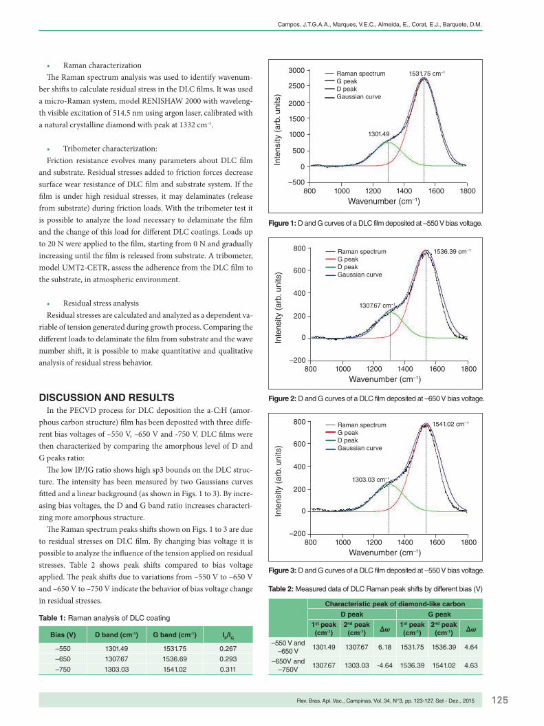
• Raman characterizationThe Raman spectrum analysis was used to identify wavenum-
ber shifts to calculate residual stress in the DLC films. It was used a micro-Raman system, model RENISHAW 2000 with waveleng-th visible excitation of 514.5 nm using argon laser, calibrated with a natural crystalline diamond with peak at 1332 cm-1.
• Tribometer characterization:Friction resistance evolves many parameters about DLC film
and substrate. Residual stresses added to friction forces decrease surface wear resistance of DLC film and substrate system. If the film is under high residual stresses, it may delaminates (release from substrate) during friction loads. With the tribometer test it is possible to analyze the load necessary to delaminate the film and the change of this load for different DLC coatings. Loads up to 20 N were applied to the film, starting from 0 N and gradually increasing until the film is released from substrate. A tribometer, model UMT2-CETR, assess the adherence from the DLC film to the substrate, in atmospheric environment.
• Residual stress analysisResidual stresses are calculated and analyzed as a dependent va-
riable of tension generated during growth process. Comparing the different loads to delaminate the film from substrate and the wave number shift, it is possible to make quantitative and qualitative analysis of residual stress behavior.
DISCuSSIoN AND ReSuLTSIn the PECVD process for DLC deposition the a-C:H (amor-
phous carbon structure) film has been deposited with three diffe-rent bias voltages of –550 V, –650 V and -750 V. DLC films were then characterized by comparing the amorphous level of D and G peaks ratio:
The low IP/IG ratio shows high sp3 bounds on the DLC struc-ture. The intensity has been measured by two Gaussians curves fitted and a linear background (as shown in Figs. 1 to 3). By incre-asing bias voltages, the D and G band ratio increases characteri-zing more amorphous structure.
The Raman spectrum peaks shifts shown on Figs. 1 to 3 are due to residual stresses on DLC film. By changing bias voltage it is possible to analyze the influence of the tension applied on residual stresses. Table 2 shows peak shifts compared to bias voltage applied. The peak shifts due to variations from –550 V to –650 V and –650 V to –750 V indicate the behavior of bias voltage change in residual stresses.
Bias (V) D band (cm-1) G band (cm-1) IP/IG
–550 1301.49 1531.75 0.267
–650 1307.67 1536.69 0.293
–750 1303.03 1541.02 0.311
Table 1: Raman analysis of DLC coating
Characteristic peak of diamond-like carbon
D peak G peak
1st peak (cm-1)
2nd peak (cm-1) Δω 1st peak
(cm-1)2nd peak
(cm-1) Δω
–550 V and –650 V
1301.49 1307.67 6.18 1531.75 1536.39 4.64
–650V and –750V
1307.67 1303.03 -4.64 1536.39 1541.02 4.63
Figure 1: D and G curves of a DLC film deposited at –550 V bias voltage.
800 1000–500
0
500
1000
1500
2000
2500
3000
1200
1301.49
Raman spectrumG peakD peakGaussian curve
1531.75 cm–1
Wavenumber (cm–1)
Inte
nsity
(ar
b. u
nits
)
1400 1600 1800
800 1000–200
0
200
400
600
800
1200
Raman spectrumG peakD peakGaussian curve
1541.02 cm–1
1303.03 cm–1
Wavenumber (cm–1)
Inte
nsity
(ar
b. u
nits
)
1400 1600 1800
800 1000–200
0
200
400
600
800
1200
Raman spectrumG peakD peakGaussian curve
1307.67 cm–1
1536.39 cm–1
Wavenumber (cm–1)
Inte
nsity
(ar
b. u
nits
)
1400 1600 1800
Figure 2: D and G curves of a DLC film deposited at –650 V bias voltage.
Figure 3: D and G curves of a DLC film deposited at –550 V bias voltage.
Table 2: Measured data of DLC Raman peak shifts by different bias (V)

126 Rev. Bras. Apl. Vac., Campinas, Vol. 34, N°3, pp. 123-127, Set - Dez., 2015
Residual stress analysis by different bias voltage of DLC films on AISI 4050 alloy steel
Table 2 shows Δω comparing the peaks of D and G band. Using Eq. 4 and k factor as –250 for a silicon surface between diamond-like carbon and substrate, it is possible to calculate the residual stress for each diamond-like film.
According to Raman spectrum analysis, residual stresses increased with increasing bias voltage. This relation is useful to identify the parameters that influence residual stresses in coatings and in its substrates surfaces. The D peak has a different behavior when comparing –650 V and –750 V. The peak variation has a negative value which due to compressive residual stresses, different from –550 V and –650 V variation, which is positive and represents tensive residual stress. Even though the peak shifts of G band is almost the same for bias voltage changes from –550 V to –650 V and from –650 V to –750 V (4.64 cm–1), the peak shift of D band decreases, resulting in a negative value as shown in table 2 for bias voltage change from –650 V to –750 V. This negative shift may be explained as the good crystalline structure ordering with higher ratios of sp2 bounds. This decreases the D band which represents the disorder of the crystalline structure in a sp2 and sp3 mix of a-C and Ta-C amorphous carbon.
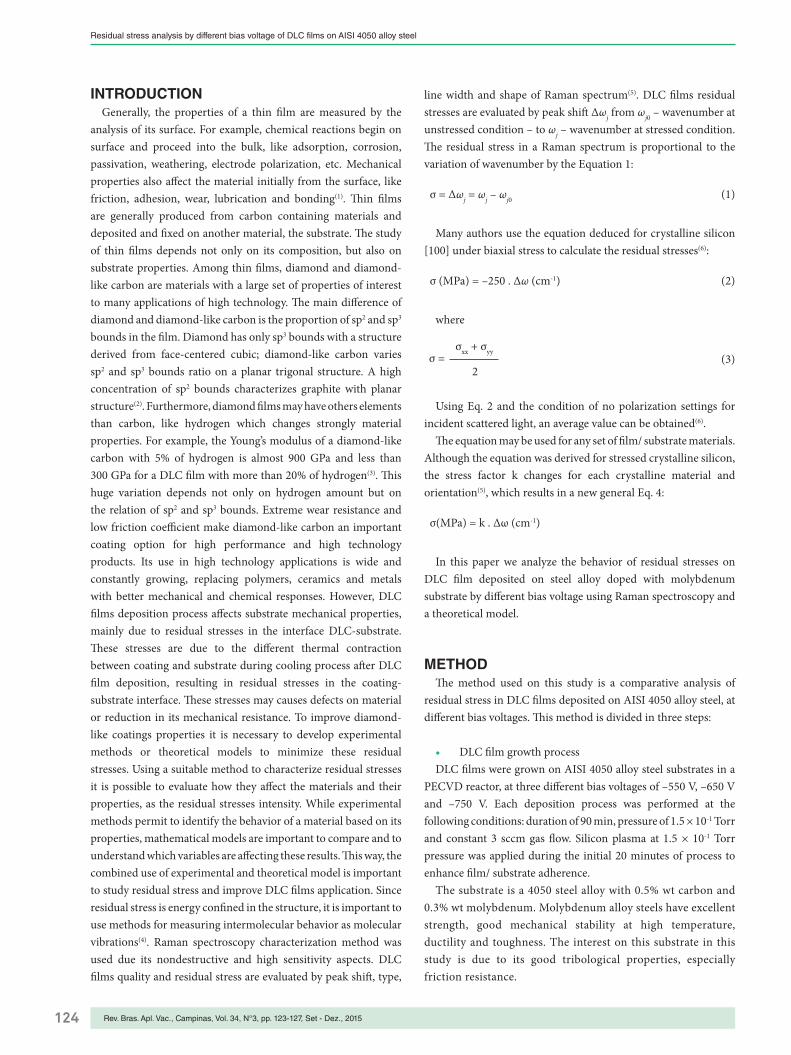
Comparing the tribometer results of each DLC film, diamond–like carbon coating with high residual stress tend to delaminate with smaller applied loads than others with low residual stresses. As shown in Figs. 4 to 6, the film deposited at the highest bias voltage (–750 V) delaminated at 9 N load, while the lowest bias voltage resulted on delamination at 12 N load. This relationship may be observed on the Table 4.
Comparing results from Raman spectrum peak shift and the tribometer results, higher bias voltage increases residual stresses in the DLC film, even it does not change its amorphous carbon
Figure 6: Tension point of film delamination for deposition at –750 V bias voltage.
Table 3: Residual stress analysis of DLC coating
ΔV (V) Δω (cm–1) Residual Stress (GPa)
–550 and –650 4.64 –1160
–650 and –750 4.63 –1157.5
Table 4: Delamination load - tribometer results
Bias voltage (V) Delamination force (N) Time (s)
–550 16 40.9
–650 12 43.0
–750 9 31.5
Figure 4: Tension point of film delamination for deposition at –550 V bias voltage.
Time (sec)40.9
0 10 20 30 40 50 601.61.4
1.2
1.0
0.80.6
0.40.2
0
COFF2N
10
–10
–15–20
–25–30
5
–5
0
Time (sec)31.5
0 10 20 30 40 50 600.24
0.20
0.16
0.12
0.08
0.04
0
COFF2N
–12
–16
–20
–4
0
–8
Time (sec)45.0
0 10 20 30 40 50 600.7
0.6
0.5
0.4
0.3
0.2
0.1
0
COFF2N
–12
–16
–20
–4
0
–8
Figure 5: Tension point of film delamination for deposition at –650 V bias voltage.
properties considerably. Using optical microscopy images, it is possible to see the delamination process under different applied loads. The film is removed from a substrate surface by a load applied on the film, which brakes and delaminates it from the substrate, pushing it away from surface.
Figure 7 shows the path done by the tribometer with 5 N load. Under load, the tip may scratch the film or, if it exceeds film/substrate adhesion, may produce delamination. In this example, the film has not delaminated and a scratch is done in the diamond-like carbon film.
Figure 8 shows a film delamination in the load scratch test. The difference of colors shows clearly that film is removed from substrate surface. The scratched path is present but the film has also broken.
Figure 9 shows the delamination of the DLC film on AISI 4045 steel under 15 N normal compressive load. Film has been remo-ved from surface and scratching lines on substrate are shown.
Figure 7: Optical microscopy image of 5 N load scratch on DLC film deposited at –750 V bias. No delamination occurs.

127Rev. Bras. Apl. Vac., Campinas, Vol. 34, N°3, pp. 123-127, Set - Dez., 2015
Campos, J.T.G.A.A., Marques, V.E.C., Almeida, E., Corat, E.J., Barquete, D.M.
Figure 9: Optical microscopy image of 15 N load scratch on DLC film deposited at –750 V bias. DLC film is removed from substrate.
Figure 8: Optical microscopy image of 10 N load scratch on DLC film deposited at –750 V bias. DLC film has delaminated from substrate.
CoNCLuSIoNResidual stress occurs on every thin film deposited on substrates
above ambient temperatures. Due to different thermal expansion coefficient of materials, these stresses arises during the cooling process from deposition temperature. Controlling the variables of deposition process it is possible to control this energy confi-ned in film and the DLC film adhesion to the substrate. The AISI 4050 molybdenum alloy steel was an adequate choice as substrate, due to the good adherence and friction resistance of the deposited
DLC. This study evaluates the behavior of residual stress by con-trolling the bias voltage applied in the plasma-enhanced chemical vapor deposition method (PECVD). The Raman spectrum has shown higher residual stresses for films with higher bias volta-ges applied. At the different bias voltages applied the DLC films has kept the same crystalline structure, evaluated by the D and G band ratio, meaning that the film adherence to the substrate chan-ged due to residual stresses in the film. Residual stress in the DLC films can be adjusted by controlling PECVD process variables, as bias voltage applied, to improve film adherence to substrate, wi-thout changing crystalline structure of the film.
ACKNoWLeDGemeNTSThe authors would like to thank CAPES for its financial support.
ReFeReNCeS
1. RADOVIC, L.R.; RODRIGUEZ−REINOSO, F., Carbon materials in catalysis. In: Thrower PA, editor. Chemistry and physics of carbon, vol 25, New York; Dekker; 1975 p. 243−358.
2. DRESSELHAUS, M. S.; DRESSELHAUS, G.; SAITO R., Physics of carbon nanotubes. Carbon 1995; 33(7): p. 883−91.
3. BROWN, D.K.; GARNER, C.E.; MUELLER, J., Unidirectional carbon/carbon for ion engine optics. Extended abstracts, 22nd biennial conf. on carbon. UC San Diego (California. USA): American Carbon Society, 1995; p. 152−3.
4. PIERSON, H. O., Handbook of carbon, diamond and fullerenes. Park Ridge NJ: Noyes. 1993: p. 87−94.
5. GHOSH, D.; SUBHASH, G.; ORLOVSKAYA, N., Measurement of scratch-induced residual stress within SiC grains in ZrB2-SiC composite using micron-Raman spectroscopy. Acta Materialia, 2008; 56: p. 5345-5354.
6. KANG, Y.; QIU, Y.; LEI, Z. et al., An aplication of Raman spectroscopy on the measurement of residual stress in porous silicon. Optics and Lasers in Engineering, 2005. 43: p. 847-855.