Embed Size (px)
Citation preview
Residual Stress, Aging and Fatigue Fracture in Injection-Molded Glassy Polymers.
11. Polycarbonate
A. V. IACOPI* and J. R. WHITE, Department of MetuUurgy and Engineering Materials, University of Newcastle upon Tyne, Newcastle
upon Tym, NEl 7RU, United Kingdom.
Synopsis
Fatigue tests have been conducted on notched polycarbonate bars molded using different conditions and having different post-molding conditioning. Fatigue crack propagation rates were not significantly modified by mechanical preconditioning prior to notching, but annealing in air caused an increase in crack growth rate. Annealing in vacuum did not cause the same effect, but specimens annealed in air or in vacuum showed a fracture surface morphology different from that obtained with unannealed bars. Changes in birefringence during cyclic loading and measurements of skin and core densities as a function of aging time were recorded, but a comprehensive interpretation of the fatigue behavior has not yet been achieved.
INTRODUCTION
In the previous paper, Part I, we have reported studies in which an attempt has been made to determine how residual stresses formed during injection molding and modified by post-molding conditioning influence fatigue crack propagation in polystyrene (PS).’ Although polycarbonate (PC) is likewise a glassy polymer, it differs quite considerably from PS in its aging and room temperature fracture behavior, and a study with similar objectives to that described in Part I has been conducted on PC in parallel with that on PS. Many of the techniques were the same, and the reader should consult Part I for details. The difference in properties dictated that in some cases tests conducted on PS were either not possible or were inappropriate with PC, as will be explained in the following sections.
EXPERIMENTAL
Specimen Production and Storage
Specimens were molded from General Electric “Lexan” with the ASTM D638 type 1 dumbbell profile and measured approximately 190 mm long and 12.7 x 3.1 mm across the gauge length. They were made on a Butler-Smith lOO/sO reciprocating screw machine with a single end-gated cavity using conditions given in Table I. PC has a fairly narrow “operating window” with
*Present address: Plessey Semiconductors Ltd., Tamerton Road, Roborough, Plymouth, Devon, U.K.
Jo~rnal Of Applied Polymer Science, Vol. 33,607-623 (1987) 0 1987 John Wiley & Sons, Inc. CCC 0021-8995/87/02W-17$O4.00
608 IACOPI AND WHITE
injection molding, and it was not found possible to make large changes in conditions and continue to produce satisfactory moldings. As part of the preliminary series of molding trials in which the best conditions were estab- lished, some experiments were conducted using different gate sizes. The larger gate permitted use of a lower mold temperature without jetting. The larger gate (L in Table I) had nearly three times the cross-sectional area of the smaller gate (S in Table I) used for the PS program as well as for much of the work on PC.
Specimens were stored at room temperature or at - 85°C as before. Those to be stored at -85°C were allowed to cool in air for 15 machine cycles and then precooled using cardice before inserting in the cold cabinet at -85°C. More details of this procedure are given in the previous paper.' A warmup time of 30 min was again allowed prior to testing specimens withdrawn from the cold cabinet.
Specimen Conditioning
Specimens were tested after conditioning in various ways, as listed below.
A. &-molded and stored at -85°C. B. Stored at -85OC and then aged at room temperature. C. Stored at -85°C and then annealed at 120°C for 5 h. D. Stored at - 85°C and then mechanically preconditioned by cylic load-
Annealing was conducted in a vacuum oven using specimens taken from the cold cabinet and allowed to equilibrate at room temperature for 20 min before inserting into the preheated oven. At the end of the annealing period the power was switched off, and the specimens were allowed to cool slowly in the oven overnight.
Mechanical preconditioning of unnotched bars was conducted as with PS using cyclic loading with modest stress amplitude (- 16.7 MN/m2).
ing.
Residual Stress Measurement
Residual stresses were measured using the layer removal p roced~re .~ -~ The version of the formula derived by Treuting and Read suitable for bars in which the curvature perpendicular to the bar axis is negligible was used as
TABLE I. Molding conditions
Delivered Temperatures ( O C) injection
preasure Gate Batch Barrel Nozzle Mold (MPa) sizea
PC-A 285/310 240 80-90 110 S PC-B 250/280 240 65 140 L PC-c 250/280 240 98 140 L
"L = larger gate; S = smaller gate.
INJECTION-MOLDED GLASSY POLYMERS. I1 609
explained in the previous paper.l i.e.,
where E is Young’s modulus, taken here to be 2.6 GN/m2 and v the Poisson ratio, taken here to be 0.38. ai(zl) is the.stress in the bar axis direction at a position z1 measured from the plane which was located at the bar center prior to layer removals, the bar surfaces located at z = fz,.
Fatigue Tests
The fatigue rigs were those used for the study of PS and earlier studies on poly(4-methyl and ~ e n t e n e - l ) ~ . ~ and have been described in detail
Tests were conducted under conditions that were essentially stress- ~ontrolled’.~,~ at a frequency of 0.083 Hz, which is sufficiently low to avoid general heating of the specimen through viscoelastic dissipation.
The specimen was placed in a constant temperature enclosure set at 30°C and for some of the tests was connected to a constant humidity generator (MCM “Aquamatique”) set to provide a relative humidity of 30%. Crack propagation studies were conducted on notched specimens using the auto- matic photographic method described b e f ~ r e . ~ ? ~ Notches produced by a broaching tool gave ductile failures over most of the stress amplitude range used here, and razor notches were adopted as standard and were used for all of the tests reported here. Even with this precaution the crack tip was sur- rounded by a whitened region, possibly containing multiple crazes; the exact location of the crack front was therefore not easy, and crack length measure- ment was subject to error.
Unnotched specimens did not fail by crack initiation and propagation within the range of loading conditions used in this work so that it was not possible to generate an S-N curve as was described for PS.’
Birefringence
The relative retardation was measured periodically during selected cyclic loading tests at a site 80 mm from the gate, as with PS.’ Unlike PS, for which measurements could be made during (slow) cycling, with PC, it was necessary to stop the test for a short time and set the specimen to the minimum strain position to make the relative retardation measurement. This is because of the greater stress sensitivity of PC, causing much more rapid changes in relative retardation for a given strain rate. The relative retardation at the high stress limit was too high to measure by the method available, again a consequence of the high stress optical sensitivity of PC. Birefringence was also measured during recovery for an extended period (unloaded) after the termination of a cyclic loading test.
Scanning Electron Microscopy
Fracture surfaces were gold-coated and examined in the scanning electron microscope (SEM) using the secondary electron image.
610 IACOPI AND WHITE
Density Measurements
Specimens were machined from the skin and the core of moldings in different states and the densities were measured using a density column. Some specimens were permitted to age in the column, and densities were monitored periodically as in the study of PS.'
RESULTS
Residual Stress Distributions
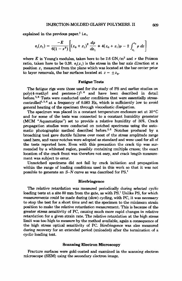
Specimens in all conditions had tensile residual stresses in the interior and compressive stresses near the surface. The magnitude of residual stresses reduced on aging in air (Fig. 1). The specimens used to obtain the data in Figure 1 had been stored at - 85°C prior to air aging. This may not be a completely inert treatment, and it is posible that the stress distribution obtained for a short aging time is influenced by low temperature storage. Previous residual stress determinations with PC have not shown such a marked departure from a parabolic distribution,' but the results in Figure 1 confirm a significant reduction of residual stress levels on room temperature aging regardless of the detailed distribution profiles.
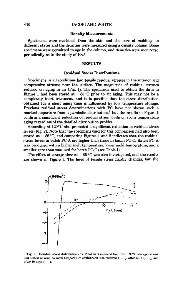
Annealing at 12OOC also promoted a significant reduction in residual stress levels (Fig. 2). Note that the specimens used for this comparison had also been stored at -85"C, and comparing Figures 1 and 2 indicates that the residual stress levels in batch PC-A are higher th& those in batch PC-C. Batch PC-A was produced with a higher melt temperature, lower mold temperature, and a smaller gate than was used for batch PC-C (see Table I).
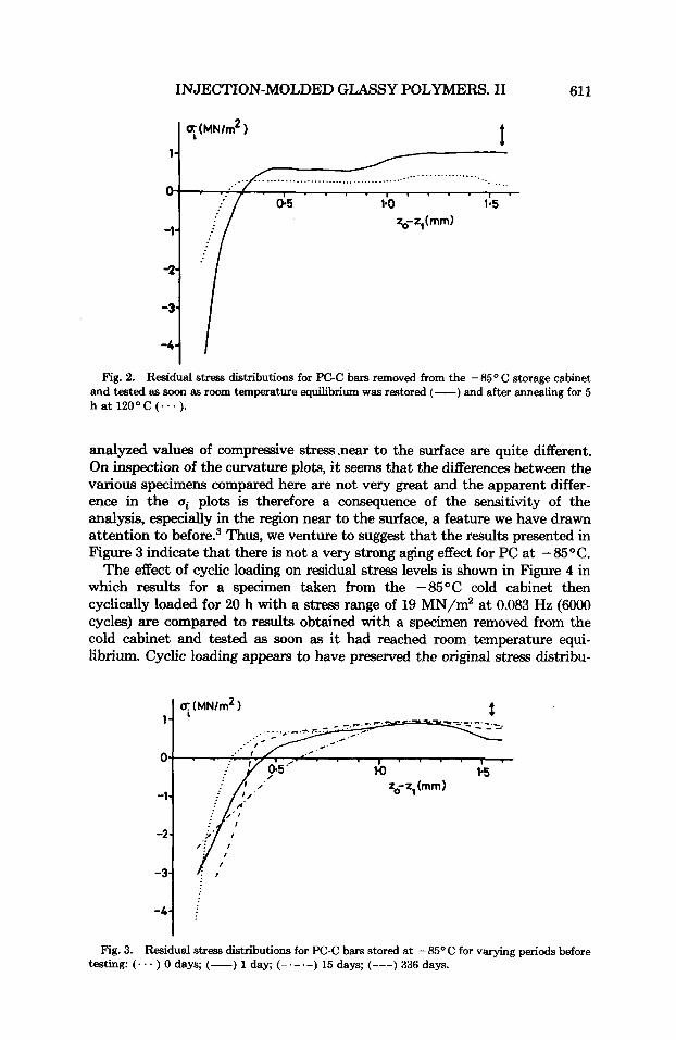
The effect of storage time at - 85 O C was also investigated, and the results are shown in Figure 3. The level of tensile stress hardly changes, but the
Fig. 1. Residual stress distributions for PC-A bars removed from the - 8 5 O C storage cabinet and tested as soon as room temperature equilibrium was restored (-), after 20 h (---), and after 10 days (. .. ).
INJECTION-MOLDED GLASSY POLYMERS. I1 61 1
1 ? ( M N / ~ * )
1- ..................... ................................... '.. ....
I . . . . , ' . . . , .
0.5 1.0 1.5 ~$-z,(mm)
Fig. 2. Residual stress distributions for PC-C bars removed from the - 85 O C storage cabinet and tested as soon as room temperature equilibrium was restored (-) and after annealing for 5 h a t 12OoC ( - - . ) .
analyzed values of compressive stressmear to the surface are quite different. On inspection of the curvature plots, it seems that the differences between the various specimens compared here are not very great and the apparent differ- ence in the ui plots is therefore a consequence of the sensitivity of the analysis, especially in the region near to the surface, a feature we have drawn attention to b e f ~ r e . ~ Thus, we venture to suggest that the results presented in Figure 3 indicate that there is not a very strong aging effect for PC at -85°C.
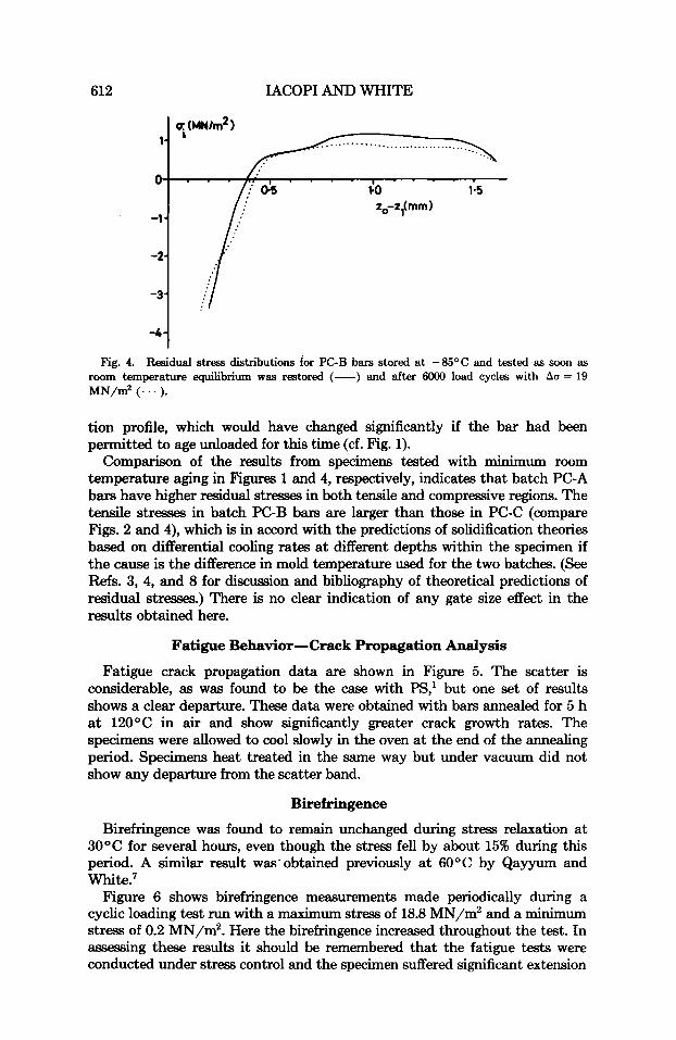
The effect of cyclic loading on residual stress levels is shown in Figure 4 in which results for a specimen taken from the -85°C cold cabinet then cyclically loaded for 20 h with a stress range of 19 MN/m2 at 0.083 Hz (so00 cycles) are compared to results obtained with a specimen removed from the cold cabinet and tested as soon as it had reached room temperature equi- librium. Cyclic loading appears to have preserved the original stress distribu-
Fig. 3. Residual stress distributions for PC-C bars stored at -85OC for varying periods before testing: (... ) 0 days; (-) 1 day; (-.-.-) 15 days; (---) 336 days.
612 IACOPI AND WHITE
I ” ” ’
1.0 1.5 zo-zl(mm)
1-
0-
-1 - -2-
-3 -
I ” ” ’
1.0 1.5 zo-zl(mm)
Fig. 4. Residual stress distributions for PC-B bars stored at -85OC and tested as soon as room temperature equilibrium was restored (-) and after 6OOO load cycles with Au = 19 MN/mz (. . . ).
tion profile, which would have changed significantly if the bar had been permitted to age unloaded for this time (cf. Fig. 1).
Comparison of the results from specimens tested with minimum room temperature aging in Figures 1 and 4, respectively, indicates that batch PC-A bars have higher residual stresses in both tensile and compressive regions. The tensile stresses in batch PC-B bars are larger than those in PC-C (compare Figs. 2 and 4), which is in accord with the predictions of solidification theories based on differential cooling rates at different depths within the specimen if the cause is the difference in mold temperature used for the two batches. (See Refs. 3, 4, and 8 for discussion and bibliography of theoretical predictions of residual stresses.) There is no clear indication of any gate size effect in the results obtained here.
Fatigue Behavior-Crack Propagation Analysis
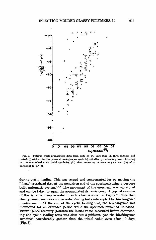
Fatigue crack propagation data are shown in Figure 5. The scatter is considerable, as was found to be the case with PS,’ but one set of results shows a clear departure. These data were obtained with bars annealed for 5 h at 120°C in air and show significantly greater crack gowth rates. The specimens were allowed to cool slowly in the oven at the end of the annealing period. Specimens heat treated in the same way but under vacuum did not show any departure from the scatter band.
Birefringence
Birefringence was found to remain unchanged during stress relaxation at 30°C for several hours, even though the stress fell by about 15% during this period. A similar result was’obtained previously at 60°C by Qayyum and white.7
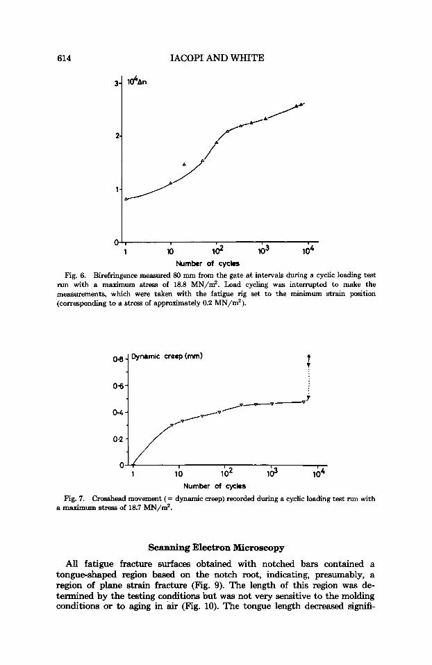
Figure 6 shows birefringence measurements made periodically during a cyclic loading test run with a maximum stress of 18.8 MN/m2 and a minimum stress of 0.2 MN/m2. Here the birefringence increased throughout the test. In assessing these results it should be remembered that the fatigue tests were conducted under stress control and the specimen suffered significant extension
INJECTION-MOLDED GLASSY POLYMERS. I1 613
-4.4
- 46 h
3 3 2 -4% v
- 8 -5.0
- 5.2
-5.4
-5.6
-58
dc
x x
X X
X
X
X
0
u . A
8
+ .
0
8
+
Fig. 5. Fatigue crack propagation data from tests on PC bars from all three batches and tested: (i) without further preconditioning (open symbols); (ii) after cyclic loading preconditioning in the unnotched state (solid symbols); (iii) after annealing in vacuum (+); and (iv) after annealing in air (x).
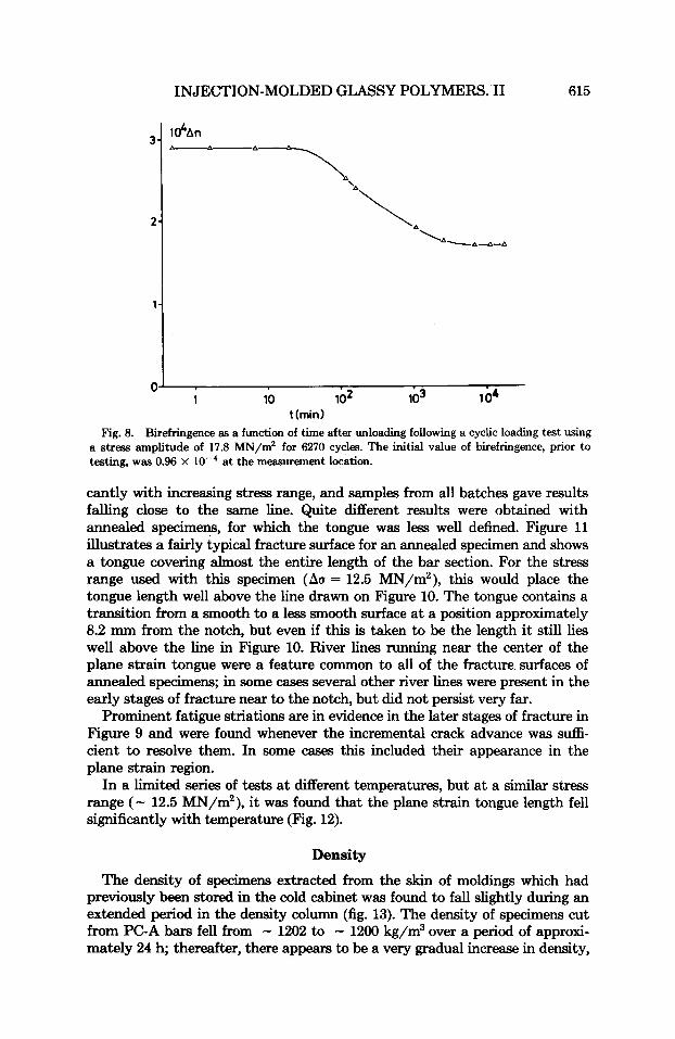
during cyclic loading. This was sensed and compensated for by moving the " fixed" crosshead (i.e., at the nondriven end of the specimen) using a purpose built automatic ~ y s t e m . ~ , ~ , ~ The movement of the crosshead was monitored and can be taken to equal the accumulated dynamic creep. A typical example of the dynamic creep recorded in such a test is shown in Figure 7. Note that the dynamic creep was not recorded during tests interrupted for birefringence measurement. At the end of the cyclic loading test, the birefringence was monitored for an extended period while the specimen remained unloaded. Birefringence recovery (towards the initial value, measured before commenc- ing the cyclic loading test) was slow but significant; yet the birefringence remained consifderably greater than the initial value even after 10 days (Fig. 8).
614 IACOPI AND WHITE
l d A n
I
1 lo Id lo3 104 Number of cycles
Fig. 6. Birefringence measured 80 mm from the gate a t intervals during a cyclic loading test run with a maximum stress of 18.8 MN/m2. Load cycling was interrupted to make the measurements, which were taken with the fatigue rig set to the minimum strain position (corresponding to a stress of approximately 0.2 MN/m2).
t ?
Number of cycks
Fig. 7. Crosshead movement (= dynamic creep) recorded during a cyclic loading test run with a maximuxn stress of 18.7 MN/m2.
Scanning Electron Microscopy
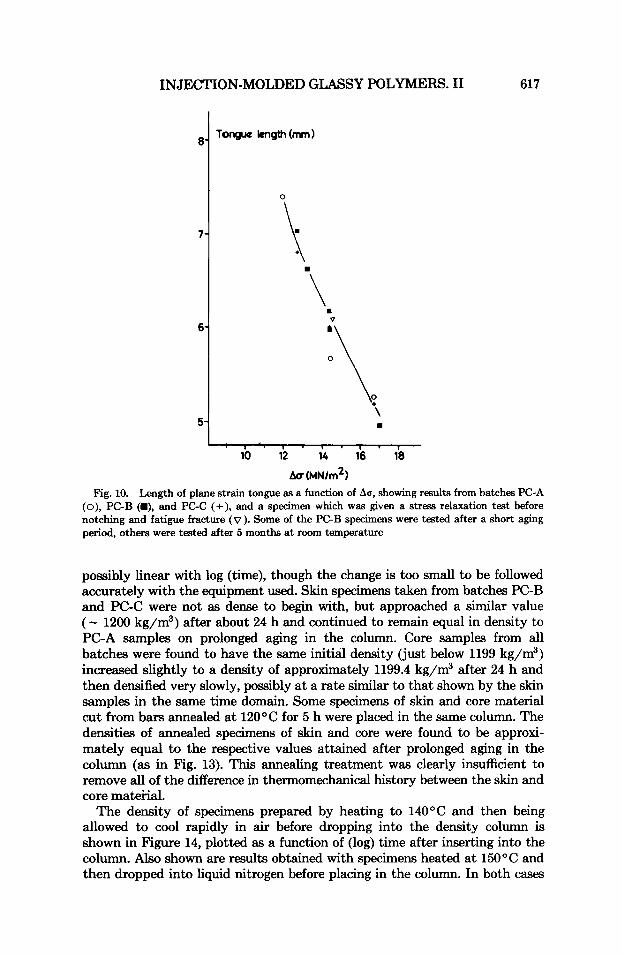
All fatigue fracture surfaces obtained with notched bars contained a tongue-shaped region based on the notch root, indicating, presumably, a region of plane strain fracture (Fig. 9). The length of this region was de- termined by the testing conditions but was not very sensitive to the molding conditions or to aging in air (Fig. 10). The tongue length decreased signifi-
INJECTION-MOLDED GLASSY POLYMERS. I1 615
1 04 0
1 10 102 103 t ( m i d
Fig. 8. Birefringence as a function of time after unloading following a cyclic loading test using a stress amplitude of 17.8 MN/m2 for 6270 cycles. The initial value of birefringence, prior to testing, was 0.96 X at the measurement location.
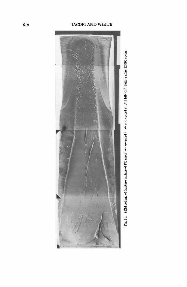
cantly with increasing stress range, and samples from all batches gave results falling close to the same line. Quite different results were obtained with annealed specimens, for which the tongue was less well defined. Figure 11 illustrates a fairly typical fracture surface for an annealed specimen and shows a tongue covering almost the entire length of the bar section. For the stress range used with this specimen (ha = 12.5 MN/m2), this would place the tongue length well above the line drawn on Figure 10. The tongue contains a transition from a smooth to a less smooth surface at a position approximately 8.2 mm from the notch, but even if this is taken to be the length it still lies well above the line in Figure 10. River lines running near the center of the plane strain tongue were a feature common to all of the fracture surfaces of annealed specimens; in some cases several other river lines were present in the early stages of fracture near to the notch, but did not persist very far.
Prominent fatigue striations are in evidence in the later stages of fracture in Figure 9 and were found whenever the incremental crack advance was suffi- cient to resolve them. In some cases this included their appearance in the plane strain region.
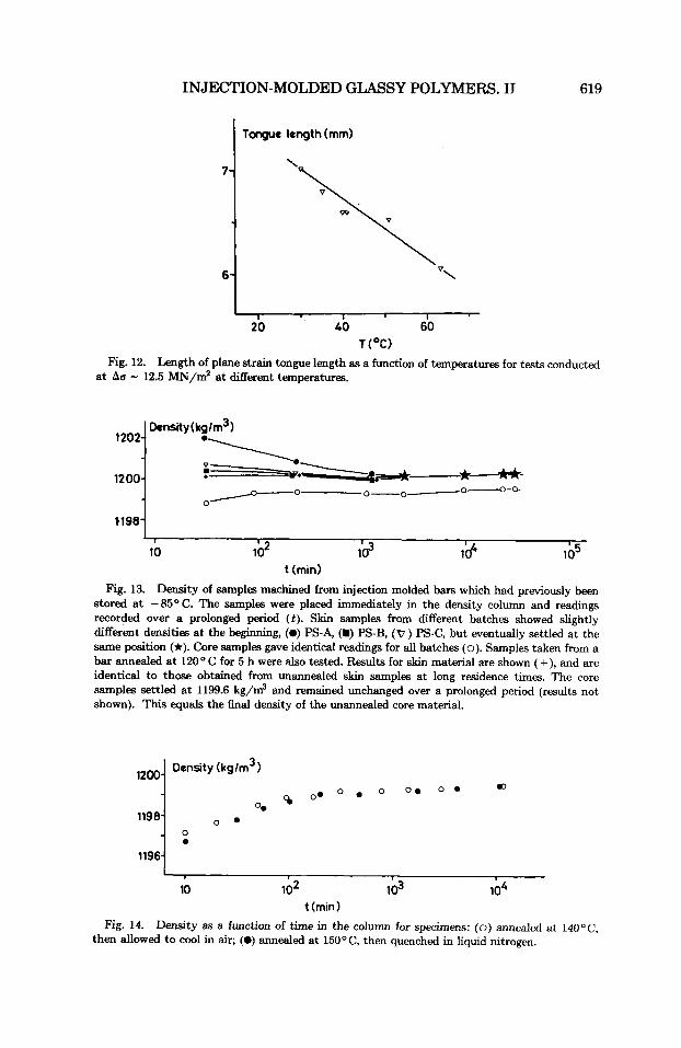
In a limited series of tests at different temperatures, but at a similar stress range (- 12.5 MN/m2), it was found that the plane strain tongue length fell significantly with temperature (Fig. 12).
Density
The density of specimens extracted from the skin of moldings which had previously been stored in the cold cabinet was found to fall slightly during an extended period in the density column (fig. 13). The density of specimens cut from PC-A bars fell from - 1202 to - 1200 kg/m3 over a period of approxi- mately 24 h; thereafter, there appears to be a very gradual increase in density,
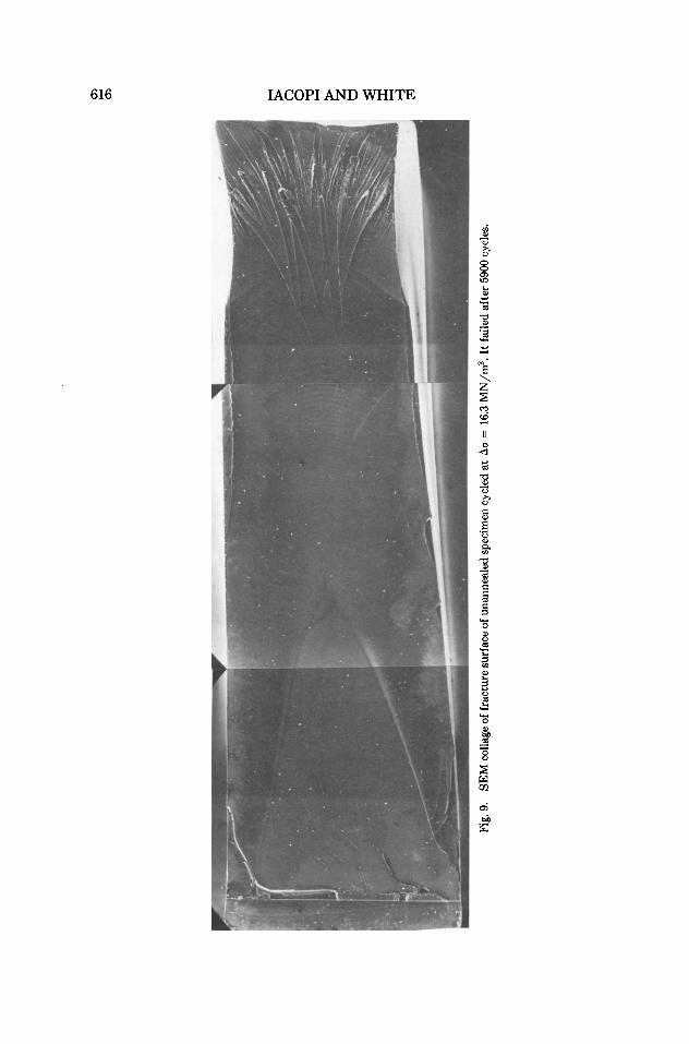
Fig. 9
. SE
M co
llage
of f
ract
ure
surf
ace o
f un
anne
aled
spec
imen
cycl
ed a
t A
o =
16.
3 M
N/m
2. I
t fai
led
afte
r 59
00 c
ycle
s.
INJEC'I'ION-MOLDED GLASSY POLYMERS. I1 617
7-
6-
5-
0
1 1 . 1 - 1 . 1 .
10 12 14 16 i8
AU (MN/~* )
Fig. 10. Length of plane strain tongue as a function of Ao, showing results from batches PC-A (o), PC-B (H), and PC-C (+), and a specimen which was given a stress relaxation test before notching and fatigue fracture ( v ). Some of the PC-B specimens were tested after a short aging period, others were tested after 5 months at room temperature
possibly linear with log (time), though the change is too small to be followed accurately with the equipment used. Skin specimens taken from batches PC-B and PC-C were not as dense to begin with, but approached a similar value (- 1200 kg/m3) after about 24 h and continued to remain equal in density to PC-A samples on prolonged aging in the column. Core samples from all batches were found to have the same initial density (just below 1199 kg/m3) increased slightly to a density of approximately 1199.4 kg/m3 after 24 h and then densified very slowly, possibly at a rate similar to that shown by the skin samples in the same time domain. Some specimens of skin and core material cut from bars annealed at 12OOC for 5 h were placed in the same column. The densities of annealed specimens of skin and core were found to be approxi- mately equal to the respective values attained after prolonged aging in the column (as in Fig. 13). This annealing treatment was clearly insufficient to remove all of the difference in thermomechanical history between the skin and core matei-ial.
The density of specimens prepared by heating to 14OOC and then being allowed to cool rapidly in air before dropping into the density column is shown in Figure 14, plotted as a function of (log) time after inserting into the column. Also shown are results obtained with specimens heated at 15OOC and then dropped into liquid nitrogen before placing in the column. In both cases
Y
Fig.
11.
SEM
colla
ge of
fra
ctur
e sur
face
of P
C sp
ecim
en a
nnea
led
in air
and
cycl
ed a
t 12
.5 M
N/m
2, f
ailin
g af
ter
22,0
00 cy
cles
.
INJECTION-MOLDED GLASSY POLYMERS. IJ
7-
6-
619
Tongue length (mm)
\
\ v\
I I I
1202
1200
1198, I
10 lb2 lb3 13 1b5 t ( m i d
Fig. 13. Density of samples machined from injection molded bars which had previously been stored at - 8 5 O C. The samples were placed immediately in the density column and readings recorded over a prolonged period (t). Skin samples from different batches showed slightly different densities a t the beginning, (0) PS-A, (H) PS-B, (v) PS-C, but eventually settled at the same position (*). Core samples gave identical readings for all batches (0). Samples taken from a bar annealed a t 120° C for 5 h were also tested. Results for skin material are shown (+), and are identical to those obtained from unannealed skin samples at long residence times. The core samples settled at 1199.6 kg/m3 and remained unchanged over a prolonged period (results not shown). This equals the final density of the unannealed core material.
Density (kg/m3) .D
Q o o o o o O e O 0 0.
0 . 1198
I
10 lo2 103 lo4 t (min 1
Fig. 14. Density as a function of time in the column for specimens: (0) annealed at 14OoC, then allowed to cool in air; (0) annealed at 150°C, then quenched in liquid nitrogen.
620 IACOPI AND WHITE
the initial density is near to 1197 kg/m3 and the material densified, reaching - 1199.2 kg/m3 after - 24 h; it then continued to further densify slowly. The behavior of these specimens is fairly similar to that of core material taken from injection moldings. This seems to indicate that the fact that the skin contains a higher amount of molecular orientation than the core and/or the fact that the skin solidifies under a high pressure (as delivered by the injection system) is more important than the cooling rate in determining density, for the cooling rate of the skin is much faster than that of the core, and closer to that achieved in the quenching experiments.
DISCUSSION
In the work reported here it was attempted to relate fatigue fracture behavior of PC with the state of the material in injection-molded bars molded under different conditions and following different post-molding thermal histo- ries. The engineering properties of polymeric components depend on the thermal history of the material; yet many of the studies of the fatigue properties of PC do not specify the thermal history. In some cases an annealing procedure was applied to remove all previous (unknown) his t~ry,~*~O but in many other studies it appears that the material was used in the as-received condition. With injection moldings the material at different loca- tions within the article will have quite different thermomechanical histories, resulting from flow during mold filling and the subsequent cooling in the mold. The material near the mold cavity wall cools quickly, even in a heated mold, and solidification occurs before the molecules, which become oriented during flow, can return to the more favored random coil conformation. In the interior of the molding the material cools much more slowly because of the low thermal conductivity of the polymer, and molecular orientation may be largely lost. In addition to the differences in degree of molecular orientation found at different locations, the state of physical aging" may be different as a consequence of the different cooling rates, and this may be indicated by differences in density or enthalpy. In a similar way it is expected that there will be a significant depth dependence of property in extruded sheet, the form used for many of the fatigue studies.
Although it is admitted that initiation of fatigue cracks probably has a very important influence over fatigue life,12 the studies reported here were directed primarily at investigating the effect of processing conditions and post-molding conditions on fatigue crack propagation, and tests were performed on bars with starter cracks. As with the studies on PS,' one of the conditioning procedures was to cyclically load unnotched bars for a prolonged period before notching and fatigue crack propagation. The purpose of this particular condi- tioning procedure was to investigate whether the cyclic loading of material ahead of a fatigue crack in any way subsequently influences the crack growth behavior. By comparing the crack .growth rates of specimens that were cyclically loaded prior to notching with those obtained at corresponding positions on specimens which were provided with a starter crack from the beginning, information on this was sought.
The fatigue crack propagation results shown in Figure 5 indicate that, within the considerable scatter, only one specimen condition has provided a
INJECTION-MOLDED GLASSY POLYMERS. I1 621
significant difference in behavior to all of the others. Specimens annealed in air for 5 h at 120°C gave much higher crack growth rates than specimens in any other condition. The fracture surfaces divided into two fairly distant classes. With specimens tested after annealing, the plane strain tongue was much longer than that found with other specimens tested under similar conditions. This was true for bars annealed in vacuum and for those annealed in air. The general appearance of the fracture surface (e.g., Fig. 11) was similar in both cases, with a tendency to form ribs within the plane strain zone, running almost parallel to the crack propagation direction. The second type of fracture surface, obtained with specimens that were not annealed, generally had a smoother appearance and had a plane strain tongue beginning at the notch and terminating long before reaching the far end of the bar section (e.g., Fig. 9). The width D of the shear lip at the edge of the fracture surface depends on the stress intensity K and on the yield stress of the material,u,,, and has been given by the approximate relationship l3
1 D = -( K/u, , )~
27r Hence
where c is the crack length. The plane strain tongue will terminate when D is equal to half the bar thickness, and, while recognizing the very approximate nature of this analysis, this predicts that the tongue length (= c at this condition) will be proportional to ( u,,/u)~. Hence increasing the stress ampli- tude should cause a reduction in tongue length, as observed. On increasing the yield strength, as occurs on annealing, the tongue length is predicted to increase, as was found here. On the other hand, when testing is conducted at a higher temperature, the yield stress decreases, predicting a fall in the tongue length, again as observed here. m e two different classes of fracture surface morphology do not seem to correlate with the crack propagation rate, how- ever, for the same kind of fracture surface was found for specimens annealed in air and those annealed in vacuum, whereas those annealed in air gave significantly higher crack propagation rates, and those annealed in vacuum gave rates similar to those found with bars in unannealed conditions.
It is not possible to find an explanation for this behavior in terms of residual stress distributions. Annealing reduced the residual stress levels considerably, but the crack propagation results obtained with vacuum- annealed bars indicated that this was not a controlling factor. It is interesting to note, however, that the residual stress distributions measured in bars that were cyclically loaded were much closer to the original profile than was the case with bars that were simply aged at room temperature for the same period of time in the unloaded state. This does not mean that no changes were taking place in the material during cyclic loading, however, for the birefringence measurements made periodically during the tests (fig. 6) show quite clearly that changes did take place.
The density results indicate there is a significant difference between skin and core material in PC. Sudden property changes at the interface between
622 IACOPI AND WHITE
the skin and the core may lead to crack initiation, as discussed in the paper on PS,’ but our observations have not been directed at examining this. I t would seem that this is an important area for investigation, particularly in view of the processing or conditioning dependence found with PS’ and with poly- sulfone14 injection moldings. The reduction in density of the skin samples, shown particularly with PC-A, over the initial aging period after removal from storage a t - 85OC, indicates, possibly, that some material aging occurs at this temperature. The effect is not as large as seen with PS,’ however, and none of the other comparisons made in this study of newly molded material and material stored at - 85OC for an extended period between molding and testing indicated significant changes. Thus, it seems that with PC the as-molded state is preserved by storage at -85°C to a much greater extent than is the case with PS.
CONCLUSIONS
The fatigue crack propagation rate in PC has been found to be fairly insensitive to injection molding conditions and to cyclic loading precondition- ing, but annealing in air caused a significant rise in crack propagation rate. The fracture surface morphology was different for annealed specimens and unannealed specimens, respectively, most likely because of an increase in the yield stress caused by annealing. The fracture surface morphology did not correlate with the crack propagation results, however, for specimens annealed in air gave crack growth rates similar to those obtained with unannealed specimens. Similarly, residual stresses do not appear to have a strong control- ling influence on crack behavior. An important result is that cyclic loading preconditioning did not leave the material more vulnerable to subsequent fatigue crack propagation (on introducing a notch), though birefringence measurement showed localized changes in molecular arrangement had taken place.
Minor changes may occur in PC at - 85°C on prolonged storage, though these are not as severe as was found with PS. The effect may be different in the skin and in the core, and this may in some circumstances lead to a modification in subsequent behavior.
The studies presented here have shown that it is not posible to correlate fatigue fracture behavior simply with the residual stress and/or the birefrin- gence of a PC molding, but that it depends in a more complicated way on the thermomechanical history of the material. More work is required to separate the several effects and to identify the controlling parameters, and should include a detailed study of fatigue crack initiation in molded articles.
The financial support of SERC is gratefully acknowledged.
References 1. A. V. Iacopi and J. R. White, J. Appl. Polym. Sci., 33, 607 (1986). 2. R. G. Treuting and W. T. Read, Jr., J . Appl. Phys., 22, 130 (1951). 3. B. Haworth, C. S. Hindle, G. J. Sandilands, and J. R. White, Plast. Rubber Process. Appl.,
4. J. R. White, Polym. Testing 4, 165 (1984) (also in Measurement T6chniques for Polymeric 2, 59 (1982).
solids, R. P. Brown and B. E. Read, Eds. Elsevier, Barking, U. K. 1984, Chap. 8).
INJECTION-MOLDED GLASSY POLYMERS. I1 623
5. G. J. Sandilands, Ph. D. thesis, University of Newcastle upon Tyne, 1983. 6. G. J. Sandilands and J. R. White, J . Appl. Polym. Sci., 30, 4771 (1985). 7. M. M. Qayyum and J. R. White, Polymer, 23, 129 (1982). 8. A. I. Isayev and D. L. Crouthamel, Polym. Plust. Technol. Eng., 22, 177 (1984). 9. N. J. Mills, Eng. Fracture Mech. 6, 537 (1974).
10. D. H. Banasiak, A. F. Grandt, Jr., and L. T. Montulli, J. Appl. Polym. Sci., 21, 1297
11. L. C. E. Struik, Physical &ng in Anw~phous Polymers and Other Materials, Elsevier,
12. K . V. Gotham and D. C. Wright, P h t . Rubber Process. Appl., 4,43 (1984). 13. R. W. Hertzberg and J. A. Manson, Fatigue of Engineering Plastics, Academic, New York,
14. J. F. Mandell, K. L. Smith, and D. D. Huang, Polym. Eng. Sci, 21, 1173 (1981).
(1977).
Amsterdam, 1978.
London, 1980.
Received November 12,1985 Accepted April 21, 1986