Embed Size (px)
Citation preview
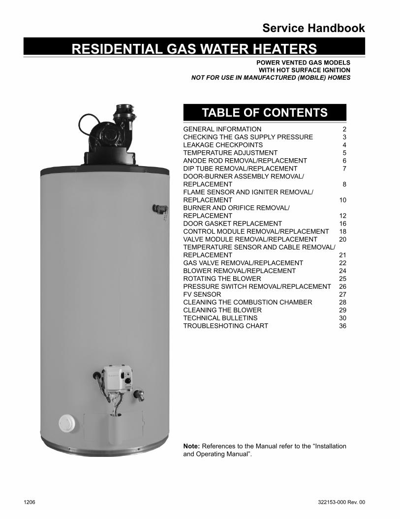
Service Handbook
1206 322153-000 Rev. 00
POWER VENTED GAS MODELS WITH HOT SURFACE IGNITION
NOT FOR USE IN MANUFACTURED (MOBILE) HOMES
RESIDENTIAL GAS WATER HEATERS
TABLE OF CONTENTS
Note: References to the Manual refer to the “Installation and Operating Manual”.
GENERAL INFORMATION 2CHECKING THE GAS SUPPLY PRESSURE 3LEAKAGE CHECKPOINTS 4TEMPERATURE ADJUSTMENT 5ANODE ROD REMOVAL/REPLACEMENT 6DIP TUBE REMOVAL/REPLACEMENT 7DOOR-BURNER ASSEMBLY REMOVAL/REPLACEMENT 8FLAME SENSOR AND IGNITER REMOVAL/REPLACEMENT 10BURNER AND ORIFICE REMOVAL/REPLACEMENT 12DOOR GASKET REPLACEMENT 16CONTROL MODULE REMOVAL/REPLACEMENT 18VALVE MODULE REMOVAL/REPLACEMENT 20TEMPERATURE SENSOR AND CABLE REMOVAL/REPLACEMENT 21GAS VALVE REMOVAL/REPLACEMENT 22BLOWER REMOVAL/REPLACEMENT 24ROTATING THE BLOWER 25PRESSURE SWITCH REMOVAL/REPLACEMENT 26FV SENSOR 27CLEANING THE COMBUSTION CHAMBER 28CLEANING THE BLOWER 29TECHNICAL BULLETINS 30TROUBLESHOTING CHART 36
2
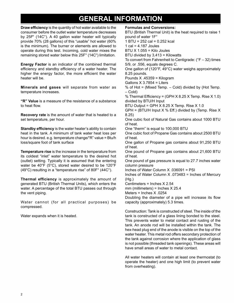
Draw effi ciency is the quantity of hot water available to the consumer before the outlet water temperature decreases by 25F° (14C°). A 40 gallon water heater will typically provide 70% (28 gallons) of this “usable” hot water (60% is the minimum). The burner or elements are allowed to operate during this test. Incoming, cold water mixes the remaining stored water below this 25F° (14C°) limitation.
Energy Factor is an indicator of the combined thermal effi ciency and standby effi ciency of a water heater. The higher the energy factor, the more effi cient the water heater will be.
Minerals and gases will separate from water as temperature increases.
“R” Value is a measure of the resistance of a substance to heat fl ow.
Recovery rate is the amount of water that is heated to a set temperature, per hour.
Standby effi ciency is the water heater’s ability to contain heat in the tank. A minimum of tank water heat loss per hour is desired. e.g. temperature change/“R” value = Btu/h loss/square foot of tank surface
Temperature rise is the increase in the temperature from its coldest “inlet” water temperature to the desired hot (outlet) setting. Typically it is assumed that the entering water be 40°F (5°C), stored water desired to be 120°F (49°C) resulting in a “temperature rise” of 80F° (44C°).
Thermal efficiency is approximately the amount of generated BTU (British Thermal Units), which enters the water. A percentage of the total BTU passes out through the vent piping.
Water cannot ( for a l l pract ica l purposes) be compressed.
Water expands when it is heated.
Formulas and Conversions:BTU (British Thermal Unit) is the heat required to raise 1 pound of water 1F°1 BTU = 252 cal = 0.252 kcal1 cal = 4.187 JoulesBTU X 1.055 = Kilo JoulesBTU divided by 3,413 = KilowattsTo convert from Fahrenheit to Centigrade: (°F – 32) times 5/9, or .556, equals degrees C.One gallon of (120°F, 49°C) water weighs approximately 8.25 pounds.Pounds X .45359 = KilogramGallons X 3.7854 = Liters% of Hot = (Mixed Temp. – Cold) divided by (Hot Temp. – Cold)% Thermal Effi ciency = (GPH X 8.25 X Temp. Rise X 1.0) divided by BTU/H InputBTU Output = GPH X 8.25 X Temp. Rise X 1.0GPH = (BTU/H Input X % Eff.) divided by (Temp. Rise X 8.25)One cubic foot of Natural Gas contains about 1000 BTU of heat.One “therm” is equal to 100,000 BTUOne cubic foot of Propane Gas contains about 2500 BTU of heat.One gallon of Propane gas contains about 91,250 BTU of heat.One pound of Propane gas contains about 21,600 BTU of heat.One pound of gas pressure is equal to 27.7 inches water column pressureInches of Water Column X .036091 = PSIInches of Water Column X .073483 = Inches of Mercury (Hg.)Centimeters = Inches X 2.54mm (millimeters) = Inches X 25.4Meters = Inches X .0254Doubling the diameter of a pipe will increase its fl ow capacity (approximately) 5.3 times.
Construction: Tank is constructed of steel. The inside of the tank is constructed of a glass lining bonded to the steel. This prevents water to metal contact and rusting of the tank. An anode rod will be installed within the tank. The hex-head plug end of the anode is visible on the top of the water heater. This metal rod offers secondary protection of the tank against corrosion where the application of glass is not possible (threaded tank openings). These areas will have small areas of water to metal contact.
All water heaters will contain at least one thermostat (to operate the heater) and one high limit (to prevent water from overheating).
GENERAL INFORMATION
3
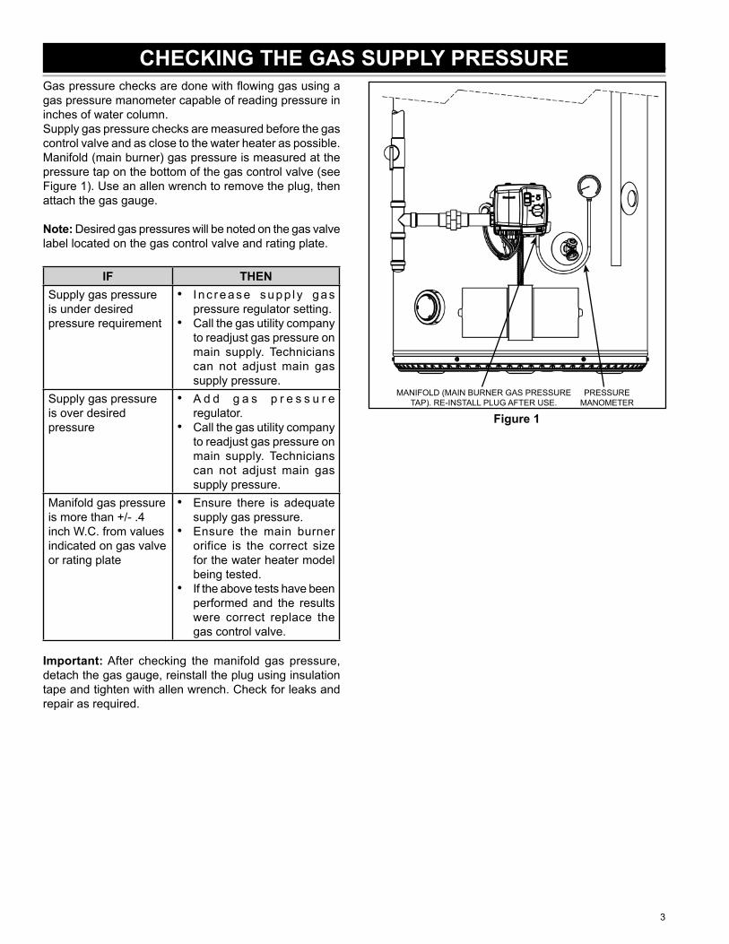
Gas pressure checks are done with fl owing gas using a gas pressure manometer capable of reading pressure in inches of water column.Supply gas pressure checks are measured before the gas control valve and as close to the water heater as possible. Manifold (main burner) gas pressure is measured at the pressure tap on the bottom of the gas control valve (see Figure 1). Use an allen wrench to remove the plug, then attach the gas gauge.
Note: Desired gas pressures will be noted on the gas valve label located on the gas control valve and rating plate.
IF THENSupply gas pressure is under desired pressure requirement
Inc rease supp l y gas pressure regulator setting.Call the gas utility company to readjust gas pressure on main supply. Technicians can not adjust main gas supply pressure.
•
•
Supply gas pressure is over desired pressure
A d d g a s p r e s s u r e regulator.Call the gas utility company to readjust gas pressure on main supply. Technicians can not adjust main gas supply pressure.
•
•
Manifold gas pressure is more than +/- .4 inch W.C. from values indicated on gas valve or rating plate
Ensure there is adequate supply gas pressure.Ensure the main burner orifice is the correct size for the water heater model being tested.If the above tests have been performed and the results were correct replace the gas control valve.
•
•
•
Important: After checking the manifold gas pressure, detach the gas gauge, reinstall the plug using insulation tape and tighten with allen wrench. Check for leaks and repair as required.
PRESSURE MANOMETER
MANIFOLD (MAIN BURNER GAS PRESSURE TAP). RE-INSTALL PLUG AFTER USE.
Figure 1
CHECKING THE GAS SUPPLY PRESSURE
4
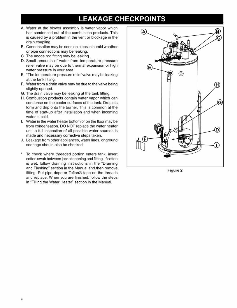
LEAKAGE CHECKPOINTSA. Water at the blower assembly is water vapor which
has condensed out of the combustion products. This is caused by a problem in the vent or blockage in the drain coupling.
B. Condensation may be seen on pipes in humid weather or pipe connections may be leaking.
C. The anode rod fi tting may be leaking.D. Small amounts of water from temperature-pressure
relief valve may be due to thermal expansion or high water pressure in your area.
E. *The temperature-pressure relief valve may be leaking at the tank fi tting.
F. Water from a drain valve may be due to the valve being slightly opened.
G. The drain valve may be leaking at the tank fi tting.H. Combustion products contain water vapor which can
condense on the cooler surfaces of the tank. Droplets form and drip onto the burner. This is common at the time of start-up after installation and when incoming water is cold.
I. Water in the water heater bottom or on the fl oor may be from condensation. DO NOT replace the water heater until a full inspection of all possible water sources is made and necessary corrective steps taken.
J. Leakage from other appliances, water lines, or ground seepage should also be checked.
* To check where threaded portion enters tank, insert cotton swab between jacket opening and fi tting. If cotton is wet, follow draining instructions in the “Draining and Flushing” section in the Manual and then remove fi tting. Put pipe dope or Tefl on® tape on the threads and replace. When you are fi nished, follow the steps in “Filling the Water Heater” section in the Manual.
ACB
D
E
F
G
I
H
Figure 2
5
SafetyDue to the nature of the typical gas water heater, the water temperature in certain situations may vary up to 30F° (16C°) higher or lower at the point of use such as bathtubs, showers, sink, etc.
HOT WATER CAN SCALD: Water heaters are intended to produce hot water. Water heated to a temperature which will satisfy space heating, clothes washing, dish washing, and other sanitizing needs can scald and permanently injure you upon contact. Some people are more likely to be permanently injured by hot water than others. These include the elderly, children, the infi rm, or physically/mentally handicapped. If anyone using hot water in your home fi ts into one of these groups or if there is a local code or state law requiring certain temperature water at the hot water tap, then you must take special precautions.
In addition of using the lowest possible temperature setting that satisfi es your hot water needs, a means such as a mixing valve should be used at the hot water taps used by these people or at the water heater. Mixing valves are available at plumbing supply or hardware stores. Follow manufacturer’s instructions for installation of the valves. Using the lowest hot water temperature that meets your needs will also provide the most energy effi cient operation of the water heater.
Never allow small children to use a hot water tap, or to draw their own bath water. Never leave a child or handicapped person unattended in a bathtub or shower.
Note: A water temperature range of 120°F-140°F (49°C-60°C) is recommended by most dishwasher manufacturers.
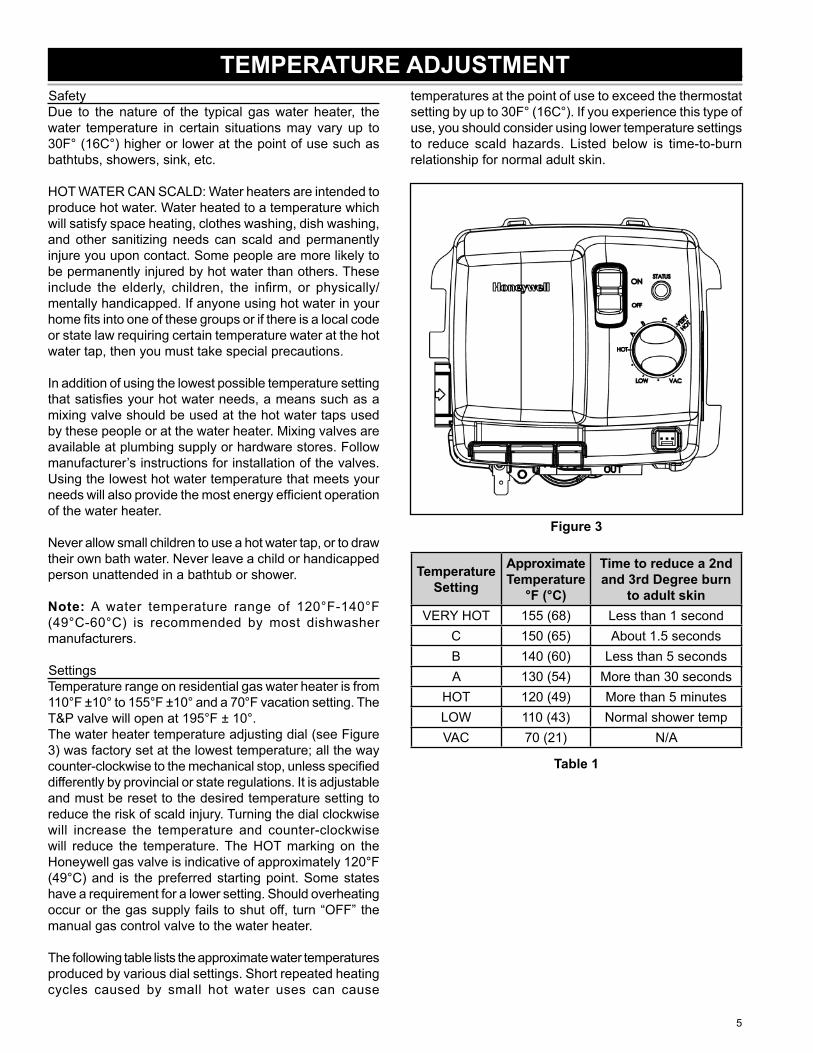
SettingsTemperature range on residential gas water heater is from 110°F ±10° to 155°F ±10° and a 70°F vacation setting. The T&P valve will open at 195°F ± 10°.The water heater temperature adjusting dial (see Figure 3) was factory set at the lowest temperature; all the way counter-clockwise to the mechanical stop, unless specifi ed differently by provincial or state regulations. It is adjustable and must be reset to the desired temperature setting to reduce the risk of scald injury. Turning the dial clockwise will increase the temperature and counter-clockwise will reduce the temperature. The HOT marking on the Honeywell gas valve is indicative of approximately 120°F (49°C) and is the preferred starting point. Some states have a requirement for a lower setting. Should overheating occur or the gas supply fails to shut off, turn “OFF” the manual gas control valve to the water heater.
The following table lists the approximate water temperatures produced by various dial settings. Short repeated heating cycles caused by small hot water uses can cause
temperatures at the point of use to exceed the thermostat setting by up to 30F° (16C°). If you experience this type of use, you should consider using lower temperature settings to reduce scald hazards. Listed below is time-to-burn relationship for normal adult skin.
Figure 3
Temperature Setting
Approximate Temperature
°F (°C)
Time to reduce a 2nd and 3rd Degree burn
to adult skinVERY HOT 155 (68) Less than 1 second
C 150 (65) About 1.5 secondsB 140 (60) Less than 5 secondsA 130 (54) More than 30 seconds
HOT 120 (49) More than 5 minutesLOW 110 (43) Normal shower tempVAC 70 (21) N/A
Table 1
TEMPERATURE ADJUSTMENT
6
ANODE RODImportant: Use only factory authorized replacement parts. If you lack the necessary skills to properly perform the installation, you should not proceed, but get help from a qualifi ed service technician.Tools required:
Ratchet with 1-1/16” SocketPliersTefl on® Tape or an approved pipe sealant
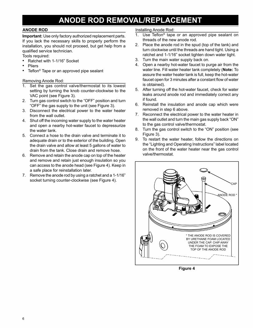
Removing Anode Rod:Set the gas control valve/thermostat to its lowest setting by turning the knob counter-clockwise to the VAC point (see Figure 3).Turn gas control switch to the “OFF” position and turn “OFF” the gas supply to the unit (see Figure 3).Disconnect the electrical power to the water heater from the wall outlet.Shut off the incoming water supply to the water heater and open a nearby hot-water faucet to depressurize the water tank.Connect a hose to the drain valve and terminate it to adequate drain or to the exterior of the building. Open the drain valve and allow at least 5 gallons of water to drain from the tank. Close drain and remove hose.Remove and retain the anode cap on top of the heater and remove and retain just enough insulation so you can access to the anode head (see Figure 4). Keep in a safe place for reinstallation later.Remove the anode rod by using a ratchet and a 1-1/16” socket turning counter-clockwise (see Figure 4).
•••
1.
2.
3.
4.
5.
6.
7.
Installing Anode Rod:Use Tefl on® tape or an approved pipe sealant on threads of the new anode rod.Place the anode rod in the spud (top of the tank) and turn clockwise until the threads are hand tight. Using a ratchet and 1-1/16” socket tighten down water tight.Turn the main water supply back on.Open a nearby hot-water faucet to purge air from the water line. Fill water heater tank completely (Note: To assure the water heater tank is full, keep the hot-water faucet open for 3 minutes after a constant fl ow of water is obtained).After turning off the hot-water faucet, check for water leaks around anode rod and immediately correct any if found.Reinstall the insulation and anode cap which were removed in step 6 above.Reconnect the electrical power to the water heater in the wall outlet and turn the main gas supply back “ON” to the gas control valve/thermostat.Turn the gas control switch to the “ON” position (see Figure 3).To restart the water heater, follow the directions on the “Lighting and Operating Instructions” label located on the front of the water heater near the gas control valve/thermostat.
CAP
ANODE ROD *
* THE ANODE ROD IS COVERED BY URETHANE FOAM LOCATED
UNDER THE CAP. CHIP AWAY THE FOAM TO EXPOSE THE
TOP OF THE ANODE ROD
Figure 4
1.
2.
3.4.
5.
6.
7.
8.
9.
ANODE ROD REMOVAL/REPLACEMENT
7
DIP TUBE REMOVAL/REPLACEMENTDIP TUBEImportant: Use only factory authorized replacement parts. If you lack the necessary skills to properly perform the installation, you should not proceed, but get help from a qualifi ed service technician.Tools required:
18” Pipe wrenchPiping and soldering equipmentTefl on® Tape or an approved pipe sealant
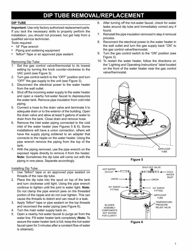
Removing Dip Tube:Set the gas control valve/thermostat to its lowest setting by turning the knob counter-clockwise to the VAC point (see Figure 3).Turn gas control switch to the “OFF” position and turn “OFF” the gas supply to the unit (see Figure 3).Disconnect the electrical power to the water heater from the wall outlet.Shut off the incoming water supply to the water heater and open a nearby hot-water faucet to depressurize the water tank. Remove pipe insulation from cold inlet piping.Connect a hose to the drain valve and terminate it to adequate drain or to the exterior of the building. Open the drain valve and allow at least 5 gallons of water to drain from the tank. Close drain and remove hose.Remove the inlet water piping connected to the cold inlet of the water heater (see Figures 5 & 6). Some installations will have a union connection, others will have the supply piping soldered to an adapter that connects to the nipple on the water heater. Using the pipe wrench remove the piping from the top of the tank.With the piping removed, use the pipe wrench on the exposed nipple directly to remove it from the heater. Note: Sometimes the dip tube will come out with the piping in one piece. Separate accordingly.
Installing Dip Tube:Use Tefl on® tape or an approved pipe sealant on threads of the new dip tube.Place the dip tube into the spud on top of the tank and turn clockwise until tight. Using the pipe wrench continue to tighten until the joint is water tight. Note: Do not clamp the pipe wrench jaws on the threaded portion of the nipple and do not over tighten. This can cause the threads to distort and can result in a leak.Apply Tefl on® tape or pipe sealant on the top threads and reconnect the water piping (see Figure 6).Turn the main water supply back on.Open a nearby hot-water faucet to purge air from the water line. Fill water heater tank completely (Note: To assure the water heater tank is full, keep the hot-water faucet open for 3 minutes after a constant fl ow of water is obtained).
•••
1.
2.
3.
4.
5.
6.
7.
1.
2.
3.
4.5.
After turning off the hot-water faucet, check for water leaks around dip tube and immediately correct any if found.Reinstall the pipe insulation removed in step 4 removal process.Reconnect the electrical power to the water heater in the wall outlet and turn the gas supply back “ON” to the gas control valve/thermostat.Turn the gas control switch to the “ON” position (see Figure 3).To restart the water heater, follow the directions on the “Lighting and Operating Instructions” label located on the front of the water heater near the gas control valve/thermostat.
NIPPLE/DIP TUBE
Figure 5
HOT-WATER OUTLET COLD-
WATER INLET
UNION UNION
3/4” SWEAT FITTING
3/4” SWEAT FITTING
TEMPERATURE-PRESSURE RELIEF VALVE
SHUT-OFF VALVE
BLOWER ASSEMBLY
COMPONENTS NOT SHOWN
FOR CLARITY.
NIPPLE/DIP TUBE
Figure 6
6.
7.
8.
9.
10.
8
INNER DOOR/MANIFOLD/BURNER ASSEMBLYImportant: Use only factory authorized replacement parts. If you lack the necessary skills to properly perform the installation, you should not proceed, but get help from a qualifi ed service technician.Tools required:
3/4” Open-End WrenchPhillips Head ScrewdriverRatchet with 1/4” socket or 1/4” nutdriverFlashlight
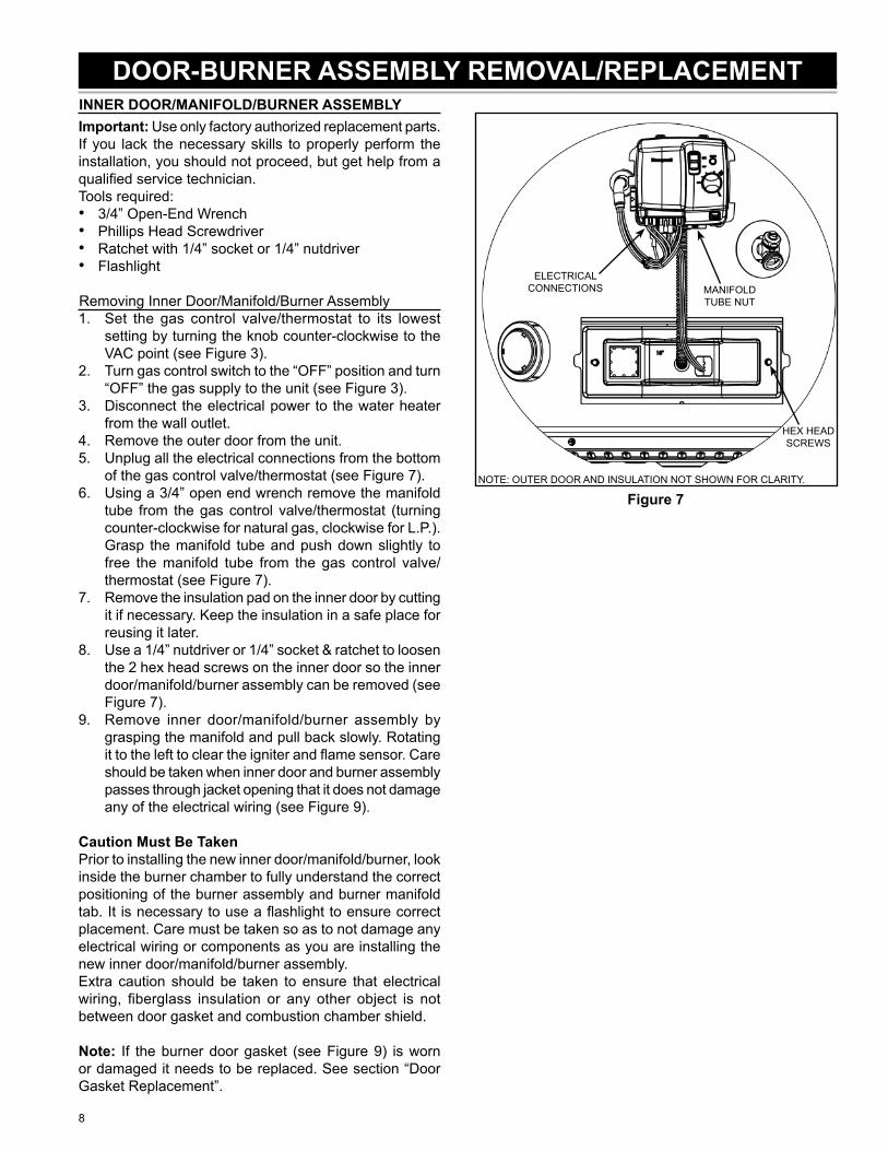
Removing Inner Door/Manifold/Burner AssemblySet the gas control valve/thermostat to its lowest setting by turning the knob counter-clockwise to the VAC point (see Figure 3).Turn gas control switch to the “OFF” position and turn “OFF” the gas supply to the unit (see Figure 3).Disconnect the electrical power to the water heater from the wall outlet.Remove the outer door from the unit.Unplug all the electrical connections from the bottom of the gas control valve/thermostat (see Figure 7).Using a 3/4” open end wrench remove the manifold tube from the gas control valve/thermostat (turning counter-clockwise for natural gas, clockwise for L.P.). Grasp the manifold tube and push down slightly to free the manifold tube from the gas control valve/thermostat (see Figure 7).Remove the insulation pad on the inner door by cutting it if necessary. Keep the insulation in a safe place for reusing it later.Use a 1/4” nutdriver or 1/4” socket & ratchet to loosen the 2 hex head screws on the inner door so the inner door/manifold/burner assembly can be removed (see Figure 7).Remove inner door/manifold/burner assembly by grasping the manifold and pull back slowly. Rotating it to the left to clear the igniter and fl ame sensor. Care should be taken when inner door and burner assembly passes through jacket opening that it does not damage any of the electrical wiring (see Figure 9).
Caution Must Be TakenPrior to installing the new inner door/manifold/burner, look inside the burner chamber to fully understand the correct positioning of the burner assembly and burner manifold tab. It is necessary to use a fl ashlight to ensure correct placement. Care must be taken so as to not damage any electrical wiring or components as you are installing the new inner door/manifold/burner assembly.Extra caution should be taken to ensure that electrical wiring, fi berglass insulation or any other object is not between door gasket and combustion chamber shield.
Note: If the burner door gasket (see Figure 9) is worn or damaged it needs to be replaced. See section “Door Gasket Replacement”.
••••
1.
2.
3.
4.5.
6.
7.
8.
9.
ELECTRICAL CONNECTIONS MANIFOLD
TUBE NUT
HEX HEAD SCREWS
NOTE: OUTER DOOR AND INSULATION NOT SHOWN FOR CLARITY.
Figure 7
DOOR-BURNER ASSEMBLY REMOVAL/REPLACEMENT
9
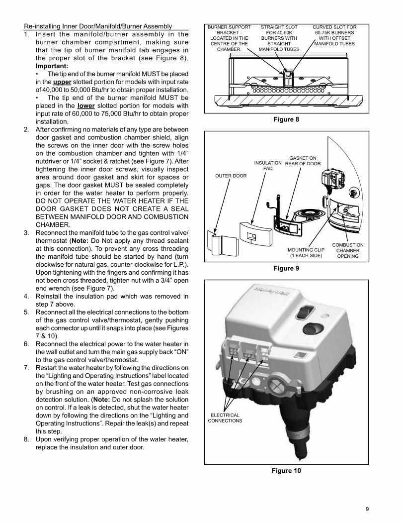
Re-installing Inner Door/Manifold/Burner AssemblyInsert the manifold/burner assembly in the burner chamber compartment, making sure that the tip of burner manifold tab engages in the proper slot of the bracket (see Figure 8).Important:• The tip end of the burner manifold MUST be placed in the upper slotted portion for models with input rate of 40,000 to 50,000 Btu/hr to obtain proper installation.• The tip end of the burner manifold MUST be placed in the lower slotted portion for models with input rate of 60,000 to 75,000 Btu/hr to obtain proper installation.After confi rming no materials of any type are between door gasket and combustion chamber shield, align the screws on the inner door with the screw holes on the combustion chamber and tighten with 1/4” nutdriver or 1/4” socket & ratchet (see Figure 7). After tightening the inner door screws, visually inspect area around door gasket and skirt for spaces or gaps. The door gasket MUST be sealed completely in order for the water heater to perform properly.DO NOT OPERATE THE WATER HEATER IF THE DOOR GASKET DOES NOT CREATE A SEAL BETWEEN MANIFOLD DOOR AND COMBUSTION CHAMBER.Reconnect the manifold tube to the gas control valve/thermostat (Note: Do Not apply any thread sealant at this connection). To prevent any cross threading the manifold tube should be started by hand (turn clockwise for natural gas, counter-clockwise for L.P.). Upon tightening with the fi ngers and confi rming it has not been cross threaded, tighten nut with a 3/4” open end wrench (see Figure 7).Reinstall the insulation pad which was removed in step 7 above.Reconnect all the electrical connections to the bottom of the gas control valve/thermostat, gently pushing each connector up until it snaps into place (see Figures 7 & 10).Reconnect the electrical power to the water heater in the wall outlet and turn the main gas supply back “ON” to the gas control valve/thermostat.Restart the water heater by following the directions on the “Lighting and Operating Instructions” label located on the front of the water heater. Test gas connections by brushing on an approved non-corrosive leak detection solution. (Note: Do not splash the solution on control. If a leak is detected, shut the water heater down by following the directions on the “Lighting and Operating Instructions”. Repair the leak(s) and repeat this step.Upon verifying proper operation of the water heater, replace the insulation and outer door.
1.
2.
3.
4.
5.
6.
7.
8.
BURNER SUPPORT BRACKET -
LOCATED IN THE CENTRE OF THE
CHAMBER.
STRAIGHT SLOT FOR 40-50K
BURNERS WITH STRAIGHT
MANIFOLD TUBES
CURVED SLOT FOR 60-75K BURNERS
WITH OFFSET MANIFOLD TUBES
Figure 8
GASKET ON REAR OF DOORINSULATION
PADOUTER DOOR
COMBUSTION CHAMBER OPENING
MOUNTING CLIP (1 EACH SIDE)
Figure 9
ELECTRICAL CONNECTIONS
Figure 10
10
FLAME SENSOR AND/OR HOT SURFACE IGNITERImportant: Use only factory authorized replacement parts. If you lack the necessary skills to properly perform the installation, you should not proceed, but get help from a qualifi ed service technician.Tools required:
3/4” Open-End WrenchPhillips Head ScrewdriverRatchet with 1/4” socket or 1/4” nutdriverFlashlightFlat Blade screwdriver
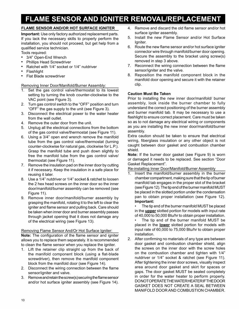
Removing Inner Door/Manifold/Burner Assembly:Set the gas control valve/thermostat to its lowest setting by turning the knob counter-clockwise to the VAC point (see Figure 3).Turn gas control switch to the “OFF” position and turn “OFF” the gas supply to the unit (see Figure 3).Disconnect the electrical power to the water heater from the wall outlet.Remove the outer door from the unit.Unplug all the electrical connections from the bottom of the gas control valve/thermostat (see Figure 11).Using a 3/4” open end wrench remove the manifold tube from the gas control valve/thermostat (turning counter-clockwise for natural gas, clockwise for L.P.). Grasp the manifold tube and push down slightly to free the manifold tube from the gas control valve/thermostat (see Figure 11).Remove the insulation pad on the inner door by cutting it if necessary. Keep the insulation in a safe place for reusing it later.Use a 1/4” nutdriver or 1/4” socket & ratchet to loosen the 2 hex head screws on the inner door so the inner door/manifold/burner assembly can be removed (see Figure 11).Remove inner door/manifold/burner assembly by grasping the manifold, rotating it to the left to clear the igniter and fl ame sensor and pulling back. Care should be taken when inner door and burner assembly passes through jacket opening that it does not damage any of the electrical wiring (see Figure 13).
Removing Flame Sensor And/Or Hot Surface Igniter:Note: The confi guration of the fl ame sensor and igniter allows you to replace them separately. It is recommended to clean the fl ame sensor when you replace the igniter.
Lift the retainer clip straight up from the back of the manifold component block (using a fl at-blade screwdriver), then remove the manifold component block from the manifold door (see Figure 14).Disconnect the wiring connection between the fl ame sensor/igniter and valve.Remove and retain the screw(s) securing the fl ame sensor and/or hot surface igniter assembly (see Figure 14).
•••••
1.
2.
3.
4.5.
6.
7.
8.
9.
1.
2.
3.
Remove and discard the old fl ame sensor and/or hot surface igniter assembly.Install the new Flame Sensor and/or Hot Surface Igniter.Route the new fl ame sensor and/or hot surface igniter connector wire through manifold/burner door opening. Secure the assembly to the bracket using screw(s) removed in step 3 above.Reconnect the wiring connection between the fl ame sensor/igniter and the valve.Reposition the manifold component block in the manifold door opening and secure it with the retainer clip.
Caution Must Be TakenPrior to installing the new inner door/manifold/ burner assembly, look inside the burner chamber to fully understand the correct positioning of the burner assembly and burner manifold tab. It may be necessary to use a fl ashlight to ensure correct placement. Care must be taken so as to not damage any electrical wiring or components as you are installing the new inner door/manifold/burner assembly.Extra caution should be taken to ensure that electrical wiring, fi berglass insulation or any other object is not caught between door gasket and combustion chamber shield.Note: If the burner door gasket (see Figure 9) is worn or damaged it needs to be replaced. See section “Door Gasket Replacement”. Re-installing Inner Door/Manifold/Burner Assembly
Insert the manifold/burner assembly in the burner chamber compartment, making sure that the tip of burner manifold tab engages in the proper slot of the bracket (see Figure 12). The tip end of the burner manifold MUST be placed in the slotted portion under the condensation pan to obtain proper installation (see Figure 12).Important:• The tip end of the burner manifold MUST be placed in the upper slotted portion for models with input rate of 40,000 to 50,000 Btu/hr to obtain proper installation.• The tip end of the burner manifold MUST be placed in the lower slotted portion for models with input rate of 60,000 to 75,000 Btu/hr to obtain proper installation.After confi rming no materials of any type are between door gasket and combustion chamber shield, align the screws on the inner door with the screw holes on the combustion chamber and tighten with 1/4” nutdriver or 1/4” socket & ratchet (see Figure 11). After tightening the inner door screws, visually inspect area around door gasket and skirt for spaces or gaps. The door gasket MUST be sealed completely in order for the water heater to perform properly.DO NOT OPERATE THE WATER HEATER IF THE DOOR GASKET DOES NOT CREATE A SEAL BETWEEN MANIFOLD DOOR AND COMBUSTION CHAMBER.
4.
5.
6.
7.
8.
1.
2.
FLAME SENSOR AND IGNITER REMOVAL/REPLACEMENT

11
Reconnect the manifold tube to the gas control valve/thermostat (Note: Do Not apply any thread sealant at this connection). To prevent any cross threading the manifold tube should be started by hand (turn clockwise for natural gas, counter-clockwise for L.P.). Upon tightening with the fi ngers and confi rming it has not been cross threaded, tighten nut with an 3/4” open end wrench (see Figure 11).Reconnect all the electrical connections to the bottom of the gas control valve/thermostat, gently pushing each connector up until it snaps into place (see Figures 10 & 11).Reconnect the electrical power to the water heater in the wall outlet and turn the main gas supply back “ON” to the gas control valve/thermostat.Restart the water heater by following the directions on the “Lighting and Operating Instructions” label located on the front of the water heater.As the burner is heating (view flames through viewport), test the manifold tube connection at the gas control valve/thermostat by brushing on an approved noncorrosive leak detection solution(Important: Do Not splash the solution onto any electrical connections. If a leak is detected, shut the water heater down by following the directions on the “Lighting and Operating Instructions”. Repair the leak(s) and repeat step 6 above).Upon verifying proper operation of the water heater, reinstall the insulation and the outer door.Note: The structure of fl ame sensor/hot surface igniter allows you to remove and replace them separately.
ELECTRICAL CONNECTIONS MANIFOLD
TUBE NUT
HEX HEAD SCREWS
NOTE: OUTER DOOR AND INSULATION NOT SHOWN FOR CLARITY.
Figure 11
3.
4.
5.
6.
7.
BURNER SUPPORT BRACKET -
LOCATED IN THE CENTRE OF THE
CHAMBER.
STRIGHT SLOT FOR 40-50K BURNERS WITH STRAIGHT
MANIFOLD TUBES
CURVED SLOT FOR 60-75K BURNERS
WITH OFFSET MANIFOLD TUBES
Figure 12
GASKET ON REAR OF DOORINSULATION
PADOUTER DOOR
COMBUSTION CHAMBER OPENING
MOUNTING CLIP (1 EACH SIDE)
Figure 13
RETAINER CLIP
IGNITER/SENSOR
ASSEMBLY
COMPONENT BLOCK
DRAIN HOLE
Figure 14
12
BURNERImportant: Use only factory authorized replacement parts. If you lack the necessary skills to properly perform the installation, you should not proceed, but get help from a qualifi ed service technician.Tools required:
3/4” Open-End WrenchPhillips Head ScrewdriverRatchet with 1/4” socket or 1/4” nutdriver.
Removing Inner Door/Manifold/Burner Assembly:Set the gas control valve/thermostat to its lowest setting by turning the knob counter-clockwise to the VAC point (see Figure 3).Turn gas control switch to the “OFF” position and turn “OFF” the gas supply to the unit (see Figure 3).Disconnect the electrical power to the water heater from the wall outlet.Remove the outer door from the unit.Unplug all the electrical connections from the bottom of the gas control valve/thermostat (see Figure 15).Using a 3/4” open end wrench remove the manifold tube from the gas control valve/thermostat (turning counter-clockwise for natural gas, clockwise for L.P.). Grasp the manifold tube and push down slightly to free the manifold tube from the gas control valve/thermostat (see Figure 15).Remove the insulation pad on the inner door by cutting it if necessary. Keep the insulation in a safe place for reusing it later.Use a 1/4” nutdriver or 1/4” socket & ratchet to loosen the 2 hex head screws on the inner door so the inner door/manifold/burner assembly can be removed (see Figure 15).Remove inner door/manifold/burner assembly by grasping the manifold, rotating it to the left to clear the igniter and fl ame sensor and pulling back. Care should be taken when inner door and burner assembly passes through jacket opening that it does not damage any of the electrical wiring (see Figure 17).
Removing Burner:Burner may be hot. Wait until burner has cooled off. After noting the position of the condensation drain hole on the top of the burner, turn the inner door/manifold/burner assembly upsidedown. Using a Phillips head screwdriver, remove and retain the 2 screws attaching the burner to the manifold pipe (see Figure 18 & 19).
Installing Burner:Care MUST be taken to ensure the burner is installed correctly on the inner door/manifold assembly. Position the new burner upside down with the orientation of the burner’s condensation drain as shown in illustration (see Figure 18 & 19).
•••
1.
2.
3.
4.5.
6.
7.
8.
9.
1.
Align the screw holes on the inner door/manifold assembly. Using the two screws removed in step 1 of Removing Burner, install the new burner to the inner door/ manifold assembly (rotate the assembly to visually check the top portion of the burner assembly and confi rm the orientation of the condensation drain hole (see Figure 19 and note).
Caution Must Be TakenPrior to installing the new inner door/manifold/burner assembly, look inside the burner chamber to fully understand the correct positioning of the burner assembly and burner manifold tab. It may be necessary to use a fl ashlight to ensure correct placement. Care must be taken so as to not damage any electrical wiring, or components as you are installing the new inner door/manifold/burner assembly. Extra caution should be taken to ensure that electrical wiring, fi berglass insulation or any other object is not between door gasket and combustion chamber shield. Note: If the burner door gasket (see Figure 9) is worn or damaged it needs to be replaced. See section “Door Gasket Replacement”. Reinstalling Inner Door/Manifold/Burner Assembly
Insert the manifold/burner assembly in the burner chamber compartment, making sure that the tip of burner manifold tab engages in the proper slot of the bracket. The tip end of the burner manifold MUST be placed in the slotted portion under the condensation pan to obtain proper installation (see Figure 16).Important:• The tip end of the burner manifold MUST be placed in the upper slotted portion for models with input rate of 40,000 to 50,000 Btu/hr to obtain proper installation.• The tip end of the burner manifold MUST be placed in the lower slotted portion for models with input rate of 60,000 to 75,000 Btu/hr to obtain proper installation.After confi rming no materials of any type are between door gasket and combustion chamber shield, align the screws on the inner door with the screw holes on the combustion chamber and tighten with 1/4” nutdriver or 1/4” socket & ratchet (see Figure 15). After tightening the inner door screws, visually inspect area around door gasket and skirt for spaces or gaps. The door gasket MUST be sealed completely in order for the water heater to perform properly.DO NOT OPERATE THE WATER HEATER IF THE DOOR GASKET DOES NOT CREATE A SEAL BETWEEN MANIFOLD DOOR AND COMBUSTION CHAMBER.Reconnect the manifold tube to the gas control valve/thermostat (Note: Do Not apply any thread sealant at this connection). To prevent any cross threading the manifold tube should be started by hand (turn clockwise for natural gas, counter-clockwise for L.P.). Upon tightening with the fi ngers and confi rming it has not been cross threaded, tighten nut with a 3/4” open end wrench (see Figure 15).
1.
1.
2.
3.
BURNER AND ORIFICE REMOVAL/REPLACEMENT
13
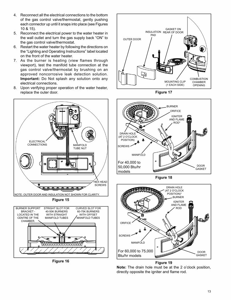
Reconnect all the electrical connections to the bottom of the gas control valve/thermostat, gently pushing each connector up until it snaps into place (see Figures 10 & 15).Reconnect the electrical power to the water heater in the wall outlet and turn the gas supply back “ON” to the gas control valve/thermostat.Restart the water heater by following the directions on the “Lighting and Operating Instructions” label located on the front of the water heater.As the burner is heating (view flames through viewport), test the manifold tube connection at the gas control valve/thermostat by brushing on an approved noncorrosive leak detection solution.Important: Do Not splash any solution onto any electrical connections.Upon verifying proper operation of the water heater, replace the outer door.
ELECTRICAL CONNECTIONS MANIFOLD
TUBE NUT
HEX HEAD SCREWS
NOTE: OUTER DOOR AND INSULATION NOT SHOWN FOR CLARITY.
Figure 15
BURNER SUPPORT BRACKET -
LOCATED IN THE CENTRE OF THE
CHAMBER.
STRIGHT SLOT FOR 40-50K BURNERS WITH STRAIGHT
MANIFOLD TUBES
CURVED SLOT FOR 60-75K BURNERS
WITH OFFSET MANIFOLD TUBES
Figure 16
4.
5.
6.
7.
8.
GASKET ON REAR OF DOORINSULATION
PADOUTER DOOR
COMBUSTION CHAMBER OPENING
MOUNTING CLIP (1 EACH SIDE)
Figure 17
For 40,000 to 50,000 Btu/hr models
SCREWS
MANIFOLD
BURNER
ORIFICE
DRAIN HOLE (AT 2 O’CLOCK
POSITION)
DOOR GASKET
IGNITER AND FLAME
ROD*
Figure 18
For 60,000 to 75,000 Btu/hr models
DRAIN HOLE (AT 2 O’CLOCK
POSITION)*
ORIFICE
SCREWS
MANIFOLD
BURNER
DOOR GASKET
IGNITER AND FLAME
ROD
Figure 19Note: The drain hole must be at the 2 o’clock position, directly opposite the igniter and fl ame rod.
14
BURNER ORIFICEImportant: Use only factory authorized replacement parts. If you lack the necessary skills to properly perform the installation, you should not proceed, but get help from a qualifi ed service technician.Tools required:
3/4” Open-End WrenchPhillips Head ScrewdriverRatchet with 1/4” socket or 1/4” nutdriverRatchet with 1/2” socket.
Removing Inner Door/Manifold/Burner AssemblySet the gas control valve/thermostat to its lowest setting by turning the knob counter-clockwise to the VAC point (see Figure 3).Turn gas control switch to the “OFF” position and turn “OFF” the gas supply to the unit (see Figure 3).Disconnect the electrical power to the water heater from the wall outlet.Remove the outer door from the unit.Unplug all the electrical connections from the bottom of the gas control valve/thermostat (see Figure 15).Using a 3/4” open end wrench remove the manifold tube from the gas control valve/thermostat (turning counter-clockwise for natural gas, clockwise for L.P.). Grasp the manifold tube and push down slightly to free the manifold tube from the gas control valve/thermostat (see Figure 15).Remove the insulation pad on the inner door by cutting it if necessary. Keep the insulation in a safe place for reusing it later.Use a 1/4” nutdriver or 1/4” socket & ratchet to loosen the 2 hex head screws on the inner door so the inner door/manifold/burner assembly can be removed (see Figure 15).Remove inner door/manifold/burner assembly by grasping the manifold, rotating it to the left to clear the igniter and fl ame sensor and pulling back. Care should be taken when inner door and burner assembly passes through jacket opening that it does not damage any of the electrical wiring (see Figure 17).
Removing Burner Orifi ceBurner may be hot. Wait until burner has cooled off. After noting the position of the condensation drain hole on the top of the burner, turn the inner door/manifold/burner assembly upsidedown. Using a Phillips head screwdriver, remove and retain the 2 screws attaching the burner to the manifold pipe (see Figure 18 & 19).Using a ratchet with 1/2” socket, remove the burner’s old orifi ce (Note: the burner orifi ces have different threads dependent upon the gas type. Orifi ces for natural gas have right-hand threads, orifi ces for L.P. have leftt-hand threads (see Figures 18 & 19).
••••
1.
2.
3.
4.5.
6.
7.
8.
9.
1.
2.
Installing Burner Orifi ceUsing a ratchet with 1/2” socket, install the new burner orifi ce (Note: the burner orifi ces have different threads dependent upon the gas type. right-handed threads for natural gas (turn clockwise to install) and left-handed threads for propane gas (turn counter-clockwise to install) (see Figures 18 & 19).Note: Determine whether the orifi ce is tall or short and DO NOT replace them with each other.Care MUST be taken to ensure the burner is installed correctly on the inner door/manifold assembly. Position the new burner upside down with the orientation of the burner’s condensation drain as noted in “Removing Burner Orifi ce” step 1.Align the screw holes on the inner door/manifold assembly. Using the two screws removed in step 1 above, installed the new burner to the inner door/ manifold assembly (rotate the assembly to visually check the top portion of the burner assembly and confi rm the orientation of the condensation drain hole as shown in the illustration) (see Figure 18 & 19).
Caution Must Be TakenPrior to installing the new inner door/manifold/burner assembly, look inside the burner chamber to fully understand the correct positioning of the burner assembly and burner manifold tab. It may be necessary to use a fl ashlight to ensure correct placement. Care must be taken so as to not damage any electrical wiring or components as you are installing the new inner door/manifold/burner assembly.Extra caution should be taken to ensure that electrical wiring, fi berglass insulation or any other object is not between door gasket and combustion chamber shield.Note: If the burner door gasket (see Figure 9) is worn or damaged it needs to be replaced. See section “Door Gasket Replacement”. Reinstalling Inner Door/Manifold/Burner Assembly
Insert the manifold/burner assembly in the burner chamber compartment, making sure that the tip of burner manifold tab engages in the proper slot of the bracket (see Figure 16).Important:• The tip end of the burner manifold MUST be placed in the upper slotted portion for models with input rate of 40,000 to 50,000 Btu/hr to obtain proper installation.* The tip end of the burner manifold MUST be placed in the lower slotted portion for models with input rate of 60,000 to 75,000 Btu/hr to obtain proper installation.After confi rming no materials of any type are between door gasket and combustion chamber shield, align the screws on the inner door with the screw holes on the combustion chamber and tighten with 1/4” nutdriver or 1/4” socket & ratchet (see Figure 15). After tightening the inner door screws, visually inspect area around door gasket and skirt for spaces or gaps. The door gasket MUST be sealed completely in order for the water heater to perform properly.
1.
2.
3.
1.
2.
15
DO NOT OPERATE THE WATER HEATER IF THE DOOR GASKET DOES NOT CREATE A SEAL BETWEEN MANIFOLD DOOR AND COMBUSTION CHAMBER.Reconnect the manifold tube to the gas control valve/thermostat (Note: Do Not apply any thread sealant at this connection). To prevent any cross threading the manifold tube should be started by hand (turn clockwise for natural gas, counter-clockwise for L.P.). Upon tightening with the fi ngers and confi rming it has not been cross threaded, tighten nut with an 3/4” open end wrench (see Figure 15).Reconnect all the electrical connections to the bottom of the gas control valve/thermostat, gently pushing each connector up until it snaps into place (see Figures 10 & 15).Reconnect the electrical power to the water heater in the wall outlet and turn the gas supply back “ON” to the gas control valve/thermostat.Restart the water heater by following the directions on the “Lighting and Operating Instructions” label located on the front of the water heater.As the burner is heating (view flames through viewport), test the manifold tube connection at the gas control valve/thermostat by brushing on an approved noncorrosive leak detection solution.Important: Do Not splash any solution onto any electrical connections.Upon verifying proper operation of the water heater, replace the outer door.
3.
4.
5.
6.
7.
8.
16
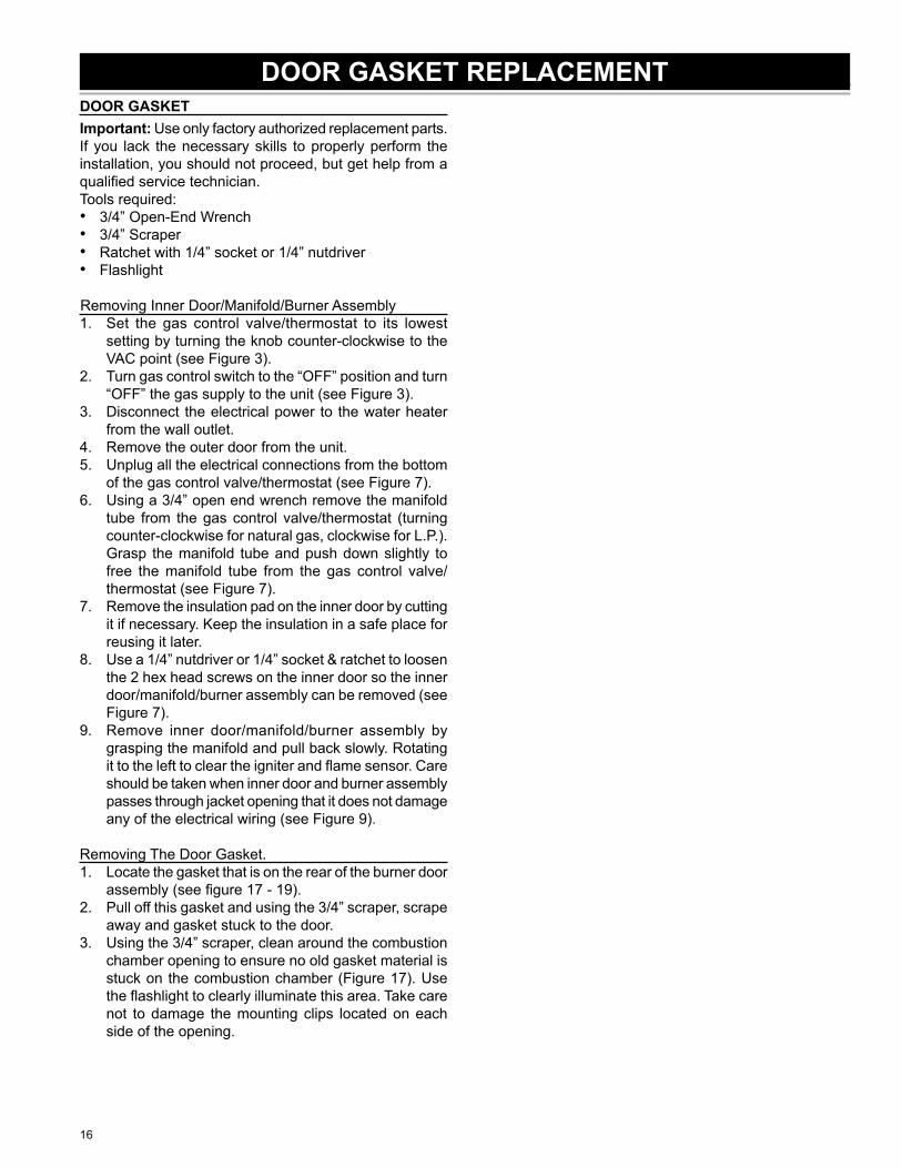
DOOR GASKETImportant: Use only factory authorized replacement parts. If you lack the necessary skills to properly perform the installation, you should not proceed, but get help from a qualifi ed service technician.Tools required:
3/4” Open-End Wrench3/4” ScraperRatchet with 1/4” socket or 1/4” nutdriverFlashlight
Removing Inner Door/Manifold/Burner AssemblySet the gas control valve/thermostat to its lowest setting by turning the knob counter-clockwise to the VAC point (see Figure 3).Turn gas control switch to the “OFF” position and turn “OFF” the gas supply to the unit (see Figure 3).Disconnect the electrical power to the water heater from the wall outlet.Remove the outer door from the unit.Unplug all the electrical connections from the bottom of the gas control valve/thermostat (see Figure 7).Using a 3/4” open end wrench remove the manifold tube from the gas control valve/thermostat (turning counter-clockwise for natural gas, clockwise for L.P.). Grasp the manifold tube and push down slightly to free the manifold tube from the gas control valve/thermostat (see Figure 7).Remove the insulation pad on the inner door by cutting it if necessary. Keep the insulation in a safe place for reusing it later.Use a 1/4” nutdriver or 1/4” socket & ratchet to loosen the 2 hex head screws on the inner door so the inner door/manifold/burner assembly can be removed (see Figure 7).Remove inner door/manifold/burner assembly by grasping the manifold and pull back slowly. Rotating it to the left to clear the igniter and fl ame sensor. Care should be taken when inner door and burner assembly passes through jacket opening that it does not damage any of the electrical wiring (see Figure 9).
Removing The Door Gasket.Locate the gasket that is on the rear of the burner door assembly (see fi gure 17 - 19).Pull off this gasket and using the 3/4” scraper, scrape away and gasket stuck to the door.Using the 3/4” scraper, clean around the combustion chamber opening to ensure no old gasket material is stuck on the combustion chamber (Figure 17). Use the fl ashlight to clearly illuminate this area. Take care not to damage the mounting clips located on each side of the opening.
••••
1.
2.
3.
4.5.
6.
7.
8.
9.
1.
2.
3.
DOOR GASKET REPLACEMENT
17
Replacing The Door Gasket.Remove the paper cover on the new door gasket. This will expose the gasket adhesive.Position the gasket on the freshly cleaned door surface so that the adhesive fi rmly holds the gasket to the door.Smooth the gasket to avoid creases.
1.
2.
3.
Re-installing Inner Door/Manifold/Burner AssemblyInsert the manifold/burner assembly in the burner chamber compartment, making sure that the tip of burner manifold tab engages in the proper slot of the bracket (see Figure 8).Important:• The tip end of the burner manifold MUST be placed in the upper slotted portion for models with input rate of 40,000 to 50,000 Btu/hr to obtain proper installation.• The tip end of the burner manifold MUST be placed in the lower slotted portion for models with input rate of 60,000 to 75,000 Btu/hr to obtain proper installation.After confi rming no materials of any type are between door gasket and combustion chamber shield, align the screws on the inner door with the screw holes on the combustion chamber and tighten with 1/4” nutdriver or 1/4” socket & ratchet (see Figure 7). After tightening the inner door screws, visually inspect area around door gasket and skirt for spaces or gaps. The door gasket MUST be sealed completely in order for the water heater to perform properly.DO NOT OPERATE THE WATER HEATER IF THE DOOR GASKET DOES NOT CREATE A SEAL BETWEEN MANIFOLD DOOR AND COMBUSTION CHAMBER.Reconnect the manifold tube to the gas control valve/thermostat (Note: Do Not apply any thread sealant at this connection). To prevent any cross threading the manifold tube should be started by hand (turn clockwise for natural gas, counter-clockwise for L.P.). Upon tightening with the fi ngers and confi rming it has not been cross threaded, tighten nut with a 3/4” open end wrench (see Figure 7).Reinstall the insulation pad which was removed in step 7 above.Reconnect all the electrical connections to the bottom of the gas control valve/thermostat, gently pushing each connector up until it snaps into place (see Figures 7 & 10).Reconnect the electrical power to the water heater in the wall outlet and turn the main gas supply back “ON” to the gas control valve/thermostat.Restart the water heater by following the directions on the “Lighting and Operating Instructions” label located on the front of the water heater. Test gas connections by brushing on an approved non-corrosive leak detection solution. (Note: Do not splash the solution on control. If a leak is detected, shut the water heater down by following the directions on the “Lighting and Operating Instructions”. Repair the leak(s) and repeat this step.Upon verifying proper operation of the water heater, replace the insulation and outer door.
1.
2.
3.
4.
5.
6.
7.
8.
18
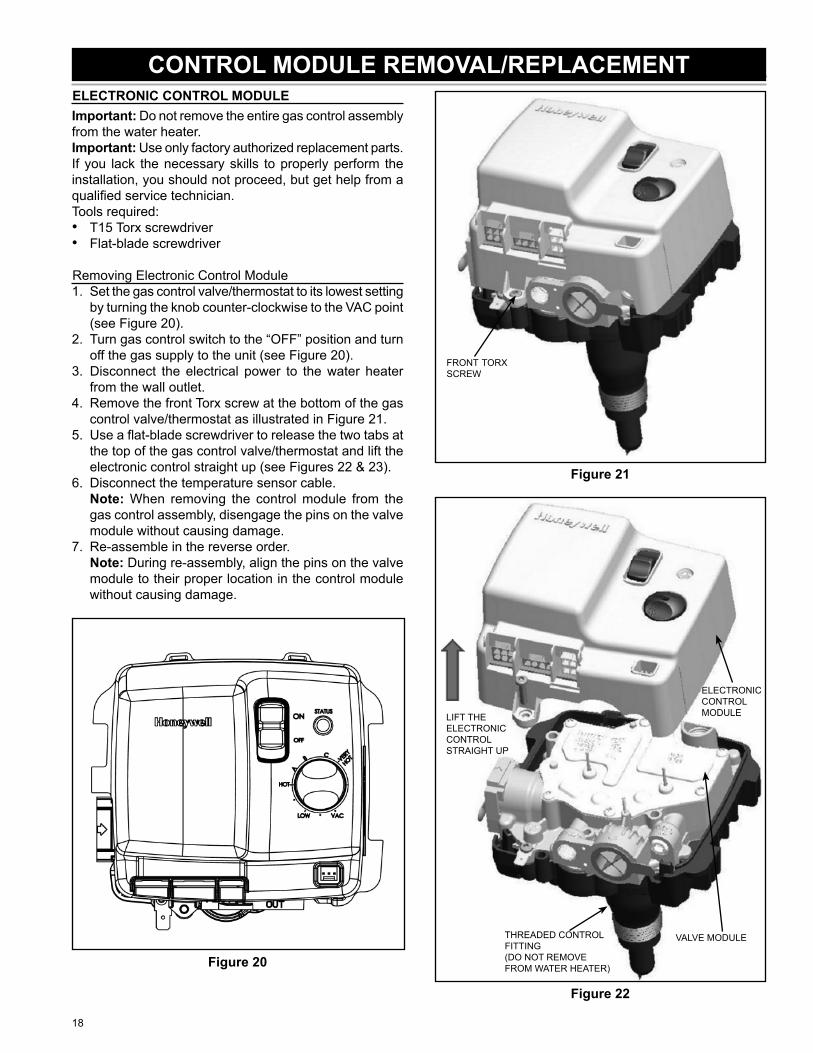
ELECTRONIC CONTROL MODULEImportant: Do not remove the entire gas control assembly from the water heater.Important: Use only factory authorized replacement parts. If you lack the necessary skills to properly perform the installation, you should not proceed, but get help from a qualifi ed service technician.Tools required:
T15 Torx screwdriverFlat-blade screwdriver
Removing Electronic Control Module1. Set the gas control valve/thermostat to its lowest setting
by turning the knob counter-clockwise to the VAC point (see Figure 20).
2. Turn gas control switch to the “OFF” position and turn off the gas supply to the unit (see Figure 20).
3. Disconnect the electrical power to the water heater from the wall outlet.
4. Remove the front Torx screw at the bottom of the gas control valve/thermostat as illustrated in Figure 21.
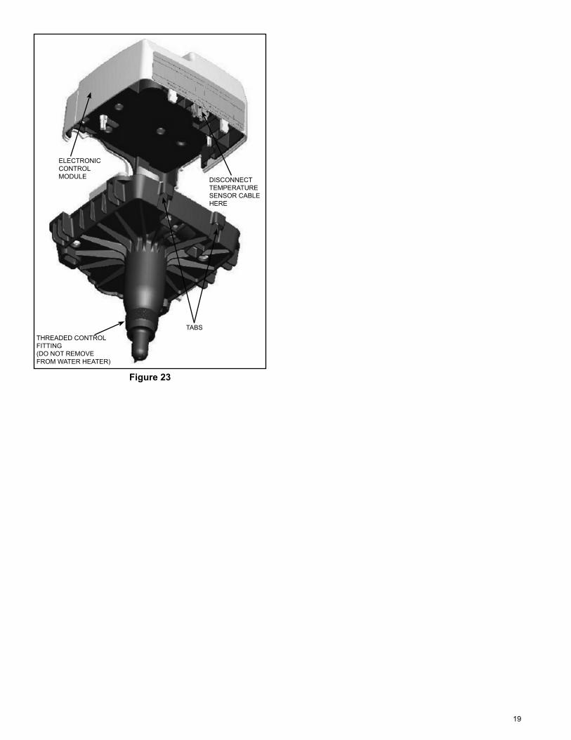
5. Use a fl at-blade screwdriver to release the two tabs at the top of the gas control valve/thermostat and lift the electronic control straight up (see Figures 22 & 23).
6. Disconnect the temperature sensor cable. Note: When removing the control module from the
gas control assembly, disengage the pins on the valve module without causing damage.
7. Re-assemble in the reverse order. Note: During re-assembly, align the pins on the valve
module to their proper location in the control module without causing damage.
Figure 20
••
FRONT TORX SCREW
Figure 21
LIFT THEELECTRONICCONTROLSTRAIGHT UP
ELECTRONIC CONTROL MODULE
VALVE MODULETHREADED CONTROL FITTING (DO NOT REMOVE FROM WATER HEATER)
Figure 22
CONTROL MODULE REMOVAL/REPLACEMENT
19
TABS
DISCONNECT TEMPERATURE SENSOR CABLE HERE
ELECTRONIC CONTROL MODULE
THREADED CONTROL FITTING (DO NOT REMOVE FROM WATER HEATER)
Figure 23
20
VALVE MODULEImportant: Do not remove the entire gas control assembly from the water heater.Important: Use only factory authorized replacement parts. If you lack the necessary skills to properly perform the installation, you should not proceed, but get help from a qualifi ed service technician.Tools required:
T15 Torx screwdriverFlat-blade screwdriver
Removing Valve Module1. Set the gas control valve/thermostat to its lowest
setting by turning the knob counter-clockwise to the VAC point (see Figure 20).
2. Turn gas control switch to the “OFF” position and turn off the gas supply to the unit (see Figure 20).
3. Disconnect the electrical power to the water heater from the wall outlet.
4. Remove the Electronic Control Module as outlined in “Removing Electronic Control Module” above.
Note: When removing the control module from the gas control assembly, disengage the pins on the valve module without causing damage.
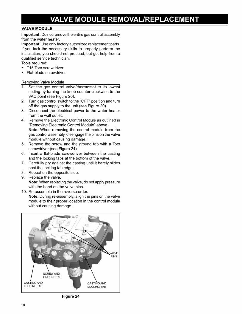
5. Remove the screw and the ground tab with a Torx screwdriver (see Figure 24).
6. Insert a fl at-blade screwdriver between the casting and the locking tabs at the bottom of the valve.
7. Carefully pry against the casting until it barely slides past the locking tab edge.
8. Repeat on the opposite side.9. Replace the valve. Note: When replacing the valve, do not apply pressure
with the hand on the valve pins.10. Re-assemble in the reverse order. Note: During re-assembly, align the pins on the valve
module to their proper location in the control module without causing damage.
CASTING AND LOCKING TAB
SCREW AND GROUND TAB
VALVEPINS
CASTING AND LOCKING TAB
Figure 24
••
VALVE MODULE REMOVAL/REPLACEMENT
21
TEMPERATURE SENSOR AND CABLEImportant: Do not remove the entire gas control assembly from the water heater.Important: Use only factory authorized replacement parts. If you lack the necessary skills to properly perform the installation, you should not proceed, but get help from a qualifi ed service technician.Tools required:
T15 Torx screwdriverFlat-blade screwdriver
Removing Temperature Sensor and Cable1. Set the gas control valve/thermostat to its lowest setting
by turning the knob counter-clockwise to the VAC point (see Figure 20).
2. Turn gas control switch to the “OFF” position and turn off the gas supply to the unit (see Figure 20).
3. Disconnect the electrical power to the water heater from the wall outlet.
4. Remove the Electronic Control Module as outlined in “Removing Electronic Control Module” section above.
Note: When removing the control module from the gas control assembly, disengage the pins on the valve module without causing damage.
5. Remove the Valve Module as outlined in ”Removing Valve Module” section above.
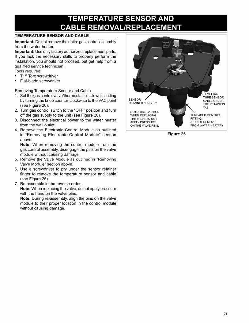
6. Use a screwdriver to pry under the sensor retainer fi nger to remove the temperature sensor and cable (see Figure 25).
7. Re-assemble in the reverse order. Note: When replacing the valve, do not apply pressure
with the hand on the valve pins. Note: During re-assembly, align the pins on the valve
module to their proper location in the control module without causing damage.
••
TEMPERA-TURE SENSOR CABLE UNDER THE RETAINING TAB
NOTE: USE CAUTION WHEN REPLACING THE VALVE TO NOT APPLY PRESSURE ON THE VALVE PINS.
SENSORRETAINER "FINGER"
THREADED CONTROL FITTING (DO NOT REMOVE FROM WATER HEATER)
Figure 25
TEMPERATURE SENSOR AND CABLE REMOVAL/REPLACEMENT
22
GAS CONTROL VALVEImportant: Use only factory authorized replacement parts. If you lack the necessary skills to properly perform the installation, you should not proceed, but get help from a qualifi ed service technician.Tools required:
3/4” Open-End Wrenchshort length of 1/2” threaded pipePipe Wrench
Removing Gas Control ValveSet the gas control valve/thermostat to its lowest setting by turning the knob counter-clockwise to the VAC point (see Figure 3).Turn gas control switch to the “OFF” position and turn off the gas supply to the unit (see Figure 3).Disconnect the electrical power to the water heater from the wall outlet.Release water pressure by opening a nearby hot water faucet, let run until water is cool to touch. Turn off water supply to the water heater.Remove the outer door from the unit.Connect a drain hose to the drain valve and run it to an adequate drain or to the exterior of the building. Open the water heater drain valve and allow the water to drain from the tank.Unplug all the electrical connections from the bottom of the gas control valve/thermostat (see Figure 26).Using a 3/4” open end wrench remove the manifold tube from the gas control valve/thermostat (turning counter-clockwise for natural gas, clockwise for L.P.). Grasp the manifold tube and push down slightly to free the manifold tube from the gas control valve/thermostat (see Figure 26).Ensuring that the gas supply line is turned off, disconnect the gas piping at the ground joint union, then remove the gas piping from the gas control valve/thermostat.Remove any other fi ttings that may be installed on the threaded pipe to the gas control valve/thermostat.After ensuring the water heater is completely drained, thread a short length of 1/2” threaded pipe into the inlet connection of the gas control valve/thermostat and use it to turn the gas control valve/thermostat counter-clockwise to remove (see Figure 27). Do not use any type of wrench on the valve body as it may cause damage to the gas control valve/thermostat assembly.
•••
1.
2.
3.
4.
5.6.
7.
8.
9.
10.
11.
Installing Gas Control ValveDo not apply any sealant tape to the gas control/thermostat threads that screw into the tank. The threads have a pre-applied white sealing material.Thread a short length of 1/2” threaded pipe into the inlet connection of the new gas control valve/thermostat and use it to turn the gas control valve/thermostat clockwise to tighten into place (Note: Do Not over tighten or damage may result, but it needs to be water tight (see Figure 27).Remove the 1/2” threaded pipe from the gas control valve/thermostat.Reconnect the gas piping to the gas control valve/thermostat, use Tefl on® tape or an approved pipe sealant on threads of the piping.Close the drain valve and turn on the cold water supply line fi lling the tank completely with water. Purge the water lines of any excess air by opening a hot water faucet allowing the water to fl ow for a minimum of 3 minutes, allowing the tank to fi ll completely.Reconnect the manifold tube to the gas control valve/thermostat (Note: Do Not apply any thread sealant at this connection). To prevent any cross threading the manifold tube should be started by hand (turn clockwise for natural gas, counter-clockwise for L.P.). Upon tightening with the fi ngers and confi rming it has not been cross threaded, tighten nut with an 3/4” open end wrench (see Figure 26).Reconnect all the electrical connections to the bottom of the gas control valve/thermostat, gently pushing each connector up snapping into place (see Figures 10 & 26).Turn on the gas supply to the unit and test the gas supply line and union connections by brushing on an approved noncorrosive leak detection solution. (Note: Do not splash the solution on control. If a leak is detected, shut the water heater down by following the directions on the “Lighting and Operating Instructions”. Repair the leak(s) and repeat leak test).Reconnect the electrical power to the water heater in the wall outlet and turn the gas supply back on to the gas control valve/thermostat.Restart the water heater by following the directions on the “Lighting and Operating Instructions” label located on the front of the water heater.As the burner is heating (view flames through viewport), test the manifold tube connection at the gas control valve/thermostat by brushing on an approved noncorrosive leak detection solution.Important: Do Not splash any solution onto any electrical connections.Upon verifying proper operation of the water heater, replace the outer door.
1.
2.
3.
4.
5.
6.
7.
8.
9.
10.
11.
12.
GAS VALVE REMOVAL/REPLACEMENT
23
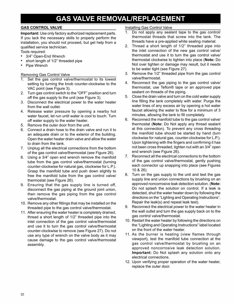
ELECTRICAL CONNECTIONS MANIFOLD
TUBE NUT
HEX HEAD SCREWS
NOTE: OUTER DOOR AND INSULATION NOT SHOWN FOR CLARITY.
Figure 26
THREADED PIPE
“HANDLE”
Figure 27
24
BLOWERImportant: Use only factory authorized replacement parts. If you lack the necessary skills to properly perform the installation, you should not proceed, but get help from a qualifi ed service technician.Tools required:
Ratchet with 5/16” socket or 5/16” nutdriverRatchet with 1/4” socket or 1/4” nutdriver
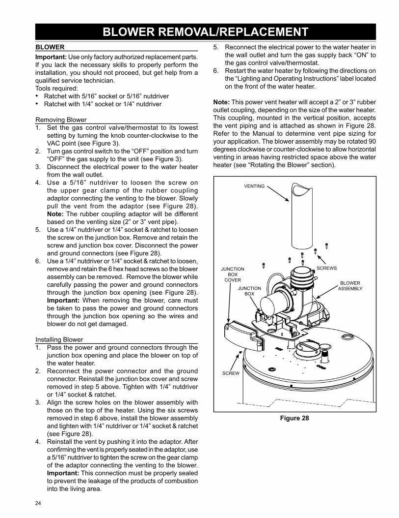
Removing BlowerSet the gas control valve/thermostat to its lowest setting by turning the knob counter-clockwise to the VAC point (see Figure 3).Turn gas control switch to the “OFF” position and turn “OFF” the gas supply to the unit (see Figure 3).Disconnect the electrical power to the water heater from the wall outlet.Use a 5/16” nutdriver to loosen the screw on the upper gear clamp of the rubber coupling adaptor connecting the venting to the blower. Slowly pull the vent from the adaptor (see Figure 28).Note: The rubber coupling adaptor will be different based on the venting size (2” or 3” vent pipe).Use a 1/4” nutdriver or 1/4” socket & ratchet to loosen the screw on the junction box. Remove and retain the screw and junction box cover. Disconnect the power and ground connectors (see Figure 28).Use a 1/4” nutdriver or 1/4” socket & ratchet to loosen, remove and retain the 6 hex head screws so the blower assembly can be removed. Remove the blower while carefully passing the power and ground connectors through the junction box opening (see Figure 28). Important: When removing the blower, care must be taken to pass the power and ground connectors through the junction box opening so the wires and blower do not get damaged.
Installing BlowerPass the power and ground connectors through the junction box opening and place the blower on top of the water heater.Reconnect the power connector and the ground connector. Reinstall the junction box cover and screw removed in step 5 above. Tighten with 1/4” nutdriver or 1/4” socket & ratchet.Align the screw holes on the blower assembly with those on the top of the heater. Using the six screws removed in step 6 above, install the blower assembly and tighten with 1/4” nutdriver or 1/4” socket & ratchet (see Figure 28).Reinstall the vent by pushing it into the adaptor. After confi rming the vent is properly seated in the adaptor, use a 5/16” nutdriver to tighten the screw on the gear clamp of the adaptor connecting the venting to the blower.Important: This connection must be properly sealed to prevent the leakage of the products of combustion into the living area.
••
1.
2.
3.
4.
5.
6.
1.
2.
3.
4.
Reconnect the electrical power to the water heater in the wall outlet and turn the gas supply back “ON” to the gas control valve/thermostat.Restart the water heater by following the directions on the “Lighting and Operating Instructions” label located on the front of the water heater.
Note: This power vent heater will accept a 2” or 3” rubber outlet coupling, depending on the size of the water heater. This coupling, mounted in the vertical position, accepts the vent piping and is attached as shown in Figure 28. Refer to the Manual to determine vent pipe sizing for your application. The blower assembly may be rotated 90 degrees clockwise or counter-clockwise to allow horizontal venting in areas having restricted space above the water heater (see “Rotating the Blower” section).
BLOWER ASSEMBLY
VENTING
SCREW
JUNCTION BOX
COVER
SCREWS
JUNCTION BOX
Figure 28
5.
6.
BLOWER REMOVAL/REPLACEMENT
25
BLOWER EXHAUST DIRECTIONImportant: Use only factory authorized replacement parts. If you lack the necessary skills to properly perform the installation, you should not proceed, but get help from a qualifi ed service technician.Tools required:
Ratchet with 11/32” socket or 11/32” nutdriver
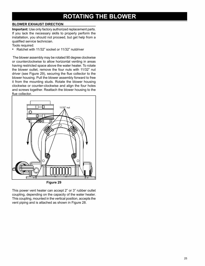
The blower assembly may be rotated 90 degree clockwise or counterclockwise to allow horizontal venting in areas having restricted space above the water heater. To rotate the blower outlet, remove the four nuts with 11/32” nut driver (see Figure 29), securing the fl ue collector to the blower housing. Pull the blower assembly forward to free it from the mounting studs. Rotate the blower housing clockwise or counter-clockwise and align the four holes and screws together. Reattach the blower housing to the fl ue collector.
11/32” nut
Figure 29
This power vent heater can accept 2” or 3” rubber outlet coupling, depending on the capacity of the water heater. This coupling, mounted in the vertical position, accepts the vent piping and is attached as shown in Figure 28.
•
ROTATING THE BLOWER
26
PRESSURE SWITCHImportant: Use only factory authorized replacement parts. If you lack the necessary skills to properly perform the installation, you should not proceed, but get help from a qualifi ed service technician.Tools required:
Phillips Head ScrewdriverRatchet with 1/4” socket or 1/4” nutdriver
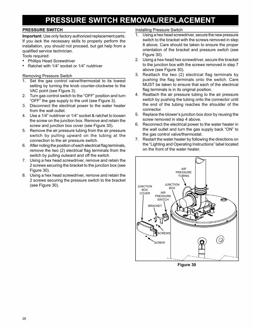
Removing Pressure SwitchSet the gas control valve/thermostat to its lowest setting by turning the knob counter-clockwise to the VAC point (see Figure 3).Turn gas control switch to the “OFF” position and turn “OFF” the gas supply to the unit (see Figure 3).Disconnect the electrical power to the water heater from the wall outlet.Use a 1/4” nutdriver or 1/4” socket & ratchet to loosen the screw on the junction box. Remove and retain the screw and junction box cover (see Figure 30).Remove the air pressure tubing from the air pressure switch by pulling upward on the tubing at the connection to the air pressure switch.After noting the position of each electrical fl ag terminals, remove the two (2) electrical fl ag terminals from the switch by pulling outward and off the switch.Using a hex head screwdriver, remove and retain the 2 screws securing the bracket to the junction box (see Figure 30).Using a hex head screwdriver, remove and retain the 2 screws securing the pressure switch to the bracket (see Figure 30).
••
1.
2.
3.
4.
5.
6.
7.
8.
Installing Pressure SwitchUsing a hex head screwdriver, secure the new pressure switch to the bracket with the screws removed in step 8 above. Care should be taken to ensure the proper orientation of the bracket and pressure switch (see Figure 30).Using a hex head hex screwdriver, secure the bracket to the junction box with the screws removed in step 7 above (see Figure 30).Reattach the two (2) electrical flag terminals by pushing the flag terminals onto the switch. Care MUST be taken to ensure that each of the electrical fl ag terminals is in its original position.Reattach the air pressure tubing to the air pressure switch by pushing the tubing onto the connector until the end of the tubing reaches the shoulder of the connector.Replace the blower’s junction box door by reusing the screw removed in step 4 above.Reconnect the electrical power to the water heater in the wall outlet and turn the gas supply back “ON” to the gas control valve/thermostat.Restart the water heater by following the directions on the “Lighting and Operating Instructions” label located on the front of the water heater.
SCREW
JUNCTION BOX
COVER
AIR PRESSURE
TUBING
AIR PRESSURE
SWITCH
BRACKET
SCREWS
JUNCTION BOX
Figure 30
1.
2.
3.
4.
5.
6.
7.
PRESSURE SWITCH REMOVAL/REPLACEMENT
27
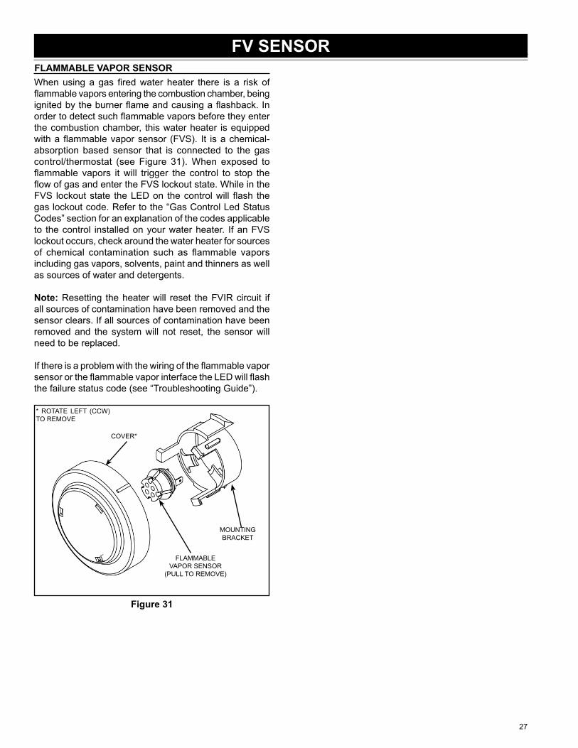
FLAMMABLE VAPOR SENSORWhen using a gas fi red water heater there is a risk of fl ammable vapors entering the combustion chamber, being ignited by the burner fl ame and causing a fl ashback. In order to detect such fl ammable vapors before they enter the combustion chamber, this water heater is equipped with a fl ammable vapor sensor (FVS). It is a chemical-absorption based sensor that is connected to the gas control/thermostat (see Figure 31). When exposed to fl ammable vapors it will trigger the control to stop the fl ow of gas and enter the FVS lockout state. While in the FVS lockout state the LED on the control will fl ash the gas lockout code. Refer to the “Gas Control Led Status Codes” section for an explanation of the codes applicable to the control installed on your water heater. If an FVS lockout occurs, check around the water heater for sources of chemical contamination such as fl ammable vapors including gas vapors, solvents, paint and thinners as well as sources of water and detergents.
Note: Resetting the heater will reset the FVIR circuit if all sources of contamination have been removed and the sensor clears. If all sources of contamination have been removed and the system will not reset, the sensor will need to be replaced.
If there is a problem with the wiring of the fl ammable vapor sensor or the fl ammable vapor interface the LED will fl ash the failure status code (see “Troubleshooting Guide”).
MOUNTING BRACKET
FLAMMABLE VAPOR SENSOR
(PULL TO REMOVE)
COVER*
* ROTATE LEFT (CCW) TO REMOVE
Figure 31
FV SENSOR
28
Follow procedure outlined in “Removing Inner Door/Manifold/Burner Assembly”.Use a vacuum cleaner/shop vac to remove all loose debris in the combustion chamber.Reassemble following the procedure under “Installing Inner Door/Manifold/Burner Assembly”.
1.
2.
3.
CLEANING THE COMBUSTION CHAMBER
29
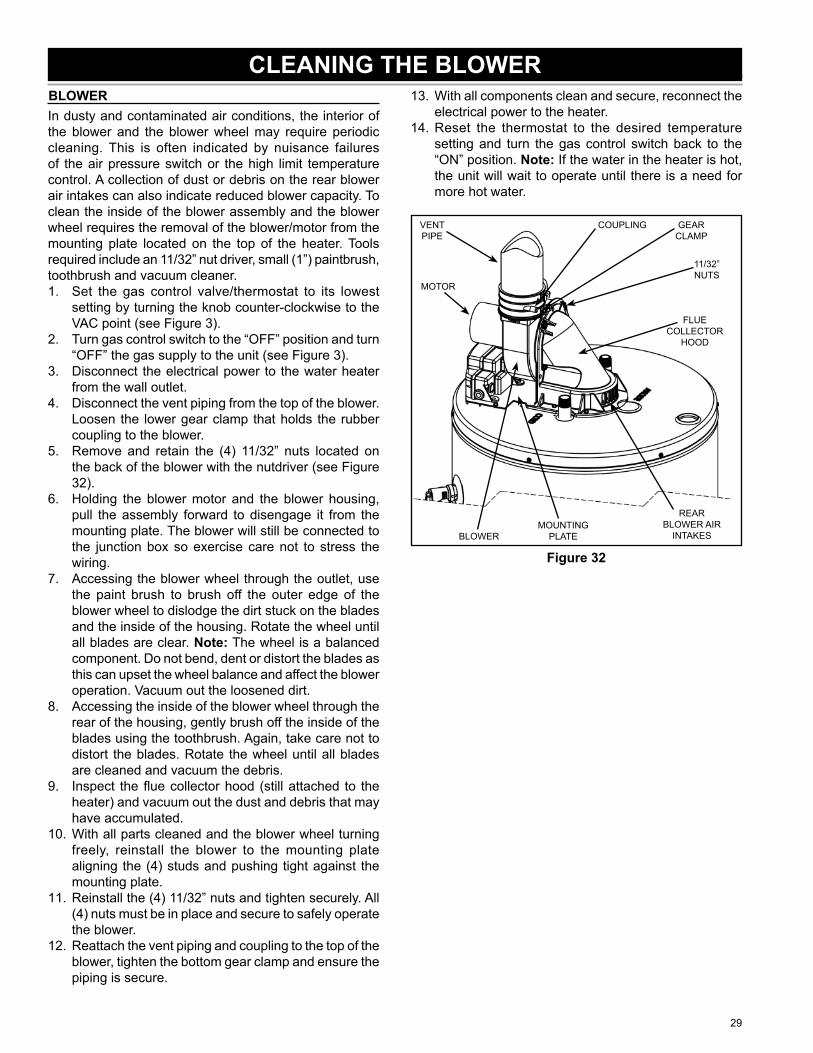
BLOWERIn dusty and contaminated air conditions, the interior of the blower and the blower wheel may require periodic cleaning. This is often indicated by nuisance failures of the air pressure switch or the high limit temperature control. A collection of dust or debris on the rear blower air intakes can also indicate reduced blower capacity. To clean the inside of the blower assembly and the blower wheel requires the removal of the blower/motor from the mounting plate located on the top of the heater. Tools required include an 11/32” nut driver, small (1”) paintbrush, toothbrush and vacuum cleaner.
Set the gas control valve/thermostat to its lowest setting by turning the knob counter-clockwise to the VAC point (see Figure 3).Turn gas control switch to the “OFF” position and turn “OFF” the gas supply to the unit (see Figure 3).Disconnect the electrical power to the water heater from the wall outlet.Disconnect the vent piping from the top of the blower. Loosen the lower gear clamp that holds the rubber coupling to the blower.Remove and retain the (4) 11/32” nuts located on the back of the blower with the nutdriver (see Figure 32).Holding the blower motor and the blower housing, pull the assembly forward to disengage it from the mounting plate. The blower will still be connected to the junction box so exercise care not to stress the wiring.Accessing the blower wheel through the outlet, use the paint brush to brush off the outer edge of the blower wheel to dislodge the dirt stuck on the blades and the inside of the housing. Rotate the wheel until all blades are clear. Note: The wheel is a balanced component. Do not bend, dent or distort the blades as this can upset the wheel balance and affect the blower operation. Vacuum out the loosened dirt.Accessing the inside of the blower wheel through the rear of the housing, gently brush off the inside of the blades using the toothbrush. Again, take care not to distort the blades. Rotate the wheel until all blades are cleaned and vacuum the debris.Inspect the fl ue collector hood (still attached to the heater) and vacuum out the dust and debris that may have accumulated.With all parts cleaned and the blower wheel turning freely, reinstall the blower to the mounting plate aligning the (4) studs and pushing tight against the mounting plate.Reinstall the (4) 11/32” nuts and tighten securely. All (4) nuts must be in place and secure to safely operate the blower.Reattach the vent piping and coupling to the top of the blower, tighten the bottom gear clamp and ensure the piping is secure.
1.
2.
3.
4.
5.
6.
7.
8.
9.
10.
11.
12.
With all components clean and secure, reconnect the electrical power to the heater.Reset the thermostat to the desired temperature setting and turn the gas control switch back to the “ON” position. Note: If the water in the heater is hot, the unit will wait to operate until there is a need for more hot water.
REAR BLOWER AIR
INTAKES
COUPLING
BLOWER
FLUE COLLECTOR
HOOD
11/32” NUTS
MOUNTING PLATE
GEAR CLAMP
VENT PIPE
MOTOR
Figure 32
13.
14.
CLEANING THE BLOWER
30
WATER HAMMERGENERAL Water hammer is the destructive force, pounding noise and vibration in a piping system when water
fl owing through a pipeline is stopped abruptly. When water hammer occurs, a high intensity pressure wave travels back through the piping system until it reaches a point of some relief. The shock wave will then surge back and forth between the point of relief and the point of stoppage until the destructive energy is dissipated in the piping system. The violent action accounts for “banging”, “thumping”, and/or intense vibration in the pipe line. Although noise is generally associated with the occurrence of water hammer, it can occur without audible sound or noise. Quick closure of valves always causes some degree of shock with or without noise. The common cause of water hammer is single lever faucets (sinks/lavatories) or automatic solenoid valves dishwashers, washing machines, etc.). The speed of the valve closure time is directly related to the intensity of the surge pressure.
EFFECTS The damage from water hammer can manifest itself in a number of ways. The most common are:• Expanded Tank Shell - This can be demonstrated by measuring the circumference at various
locations along the shell. Pressures in excess of the maximum design working pressure can cause permanent deformation of the shell. Note: The continuous expansion of the tank shell may cause the tank to rupture at a welded seam.
• Collapsed Flue Tube - This will choke off the ability to vent the products of combustion causing the fl ame and/or combustion to spill out from the combustion chamber. Often this will occur where thinning of the fl ue tube walls has occurred due to contamination of the combustion air or because of excessive condensation.
• Inverted or Deformed Tank Heads - Often this accompanies collapsed fl ues, but one or both heads can be deformed.
THE FIX The only effective means of control is to install water hammer arrestors. These devices have diaphragms which separate an air chamber from the water in the piping system. As the shock wave reaches this device, the air chamber absorbs the shock. Arrestors should be located as close as possible to the source of the shock wave.
NOTES Since water hammer exposes the equipment to pressures in excess of its design limits, failures caused by water hammer are not eligible for warranty consideration.
MINERAL BUILD-UPSYMPTOMS • Rumbling
• Crackling• Popping
CAUSE With the increase in fuel costs and hot water consumption, deliming has become a necessity of modern maintenance. Lime (CaCO3), is the most notable factor when discussing water hardness. Lime is present in every water system to some degree. Since lime is inversely soluble (the more you heat, the more lime comes out), higher usage, excessive hardness, and increased heating surface can lead to a high incidence of “limed-up” heaters. Symptoms often include a popping of water trapped under lime deposits or the sizzling of water trapped next to elements, boiling it to steam.
THE FIX Treatment of a “limed-up“ heater is relatively simple. Since CaCO3 is a base, the easiest way to dissolve it so it can be fl ushed from the heater is with an acid. The most commonly used is phosphoric acid at a food-grade level. Two available treatments are Mag-Erad® and Un-Lime®. Any well stocked plumbing supply house should have a deliming solution available. The directions on the product should be followed explicitly.
TECHNICAL BULLETINS
31
CONDENSATIONSYMPTOMS The water heater appears to be releasing water while the main burner is on or water is found
surrounding the heater shortly after the water heater has been used. This section explains why fl ue gases condense and how you can differentiate between condensation and leaking.
CAUSES Condensate is the result of air borne water vapor being chilled below the dew point. The dew point is the temperature at which water vapor turns into liquid. Low incoming water temperatures cool the piping and the heat transfer surfaces of the water heater. When the main burner comes on, the hot fl ue gases turn into condensate upon contact with these surfaces. The typical home water heater will produce about one-half gallon of water vapor during every hour of operation. Condensate is often mistaken for leaking. Newer heaters will condensate more than older heaters because modern water heaters are much more effi cient than their predecessors. The newer heaters utilize as much of the energy out of the main burner fl ame as possible. This lowers the fl ue gas and tank storage temperature and closer to the dew point temperature.
THE FIX To distinguish between a condensating water heater and a leaking water heater:1. Wipe up any water under the heater,2. Turn gas control switch to the “OFF” position,3. Wait 8 hours, check for water accumulation under the heater.4. Condensation should stop when the entire tank water is heated above approximately 115°F.
a. If no water is under the heater, the water heater was condensating.b. If water is under the heater, check further for a loose fi tting. If all fi ttings are tight and the tank
is leaking, replace the water heater. Leaking heaters cannot be “repaired”.
DISCOLORED WATERSYMPTOMS Rusty, brown, black, or yellow water appearing in the hot water.CAUSES Complaints of discolored water are commonly blamed on water heaters and storage tanks, but in
fact, it is a rare occurrence for today’s high quality glass lined tanks to have a lining failure signifi cant enough to allow water to contact enough bare metal to discolor the contents of even a small tank. The most common cause of “rusty” water is a non-toxic iron reducing bacteria, scientifi cally termed Crenothrix, Leptothrix, and Gallionella. Iron bacteria is commonly found in soil, water wells, water treatment plants and water distribution piping systems where soluble iron exceeds 0.2 ppm, higher levels make conditions even more favorable. Soluble iron in the water provides food for the bacteria. Rusty discolored water is the end result of the bacteria feeding process. Water heaters and storage tanks usually require new anode rods as presence of iron bacteria contributes to premature anode failure.
The requirements for the bacteria to thrive are:• Elevated levels of iron and manganese in the water.• Water with little or no dissolved oxygen.• Temperatures below 138°F.
Items that can increase the potential for this bacteria are:• Water softeners.• Well water.• Long periods of no water movement.
TREATMENT The simplest treatment available is shock-chlorination of the system. This is a surface treatment, and often requires repeated trials in heavily infected systems. The chlorination of a system requires that you follow each step explicitly to avoid an untreated portion of the piping system from re-infecting another part. See the “Chlorination Procedure” section.
NOTES Since rusty water is caused by a bacteria presence and is not caused by the water heater, any treatment would not be considered warranty related.
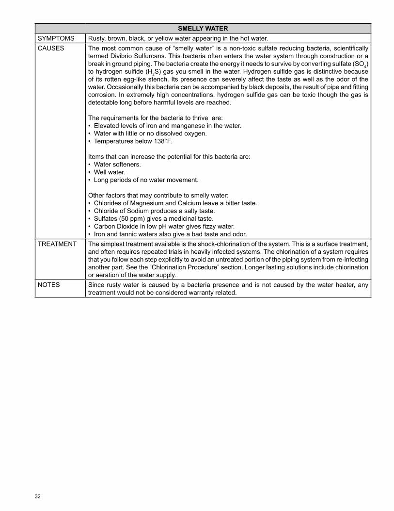
32
SMELLY WATERSYMPTOMS Rusty, brown, black, or yellow water appearing in the hot water.CAUSES The most common cause of “smelly water” is a non-toxic sulfate reducing bacteria, scientifi cally
termed Divibrio Sulfurcans. This bacteria often enters the water system through construction or a break in ground piping. The bacteria create the energy it needs to survive by converting sulfate (SO4) to hydrogen sulfi de (H2S) gas you smell in the water. Hydrogen sulfi de gas is distinctive because of its rotten egg-like stench. Its presence can severely affect the taste as well as the odor of the water. Occasionally this bacteria can be accompanied by black deposits, the result of pipe and fi tting corrosion. In extremely high concentrations, hydrogen sulfi de gas can be toxic though the gas is detectable long before harmful levels are reached.
The requirements for the bacteria to thrive are:• Elevated levels of iron and manganese in the water.• Water with little or no dissolved oxygen.• Temperatures below 138°F.
Items that can increase the potential for this bacteria are:• Water softeners.• Well water.• Long periods of no water movement.
Other factors that may contribute to smelly water:• Chlorides of Magnesium and Calcium leave a bitter taste.• Chloride of Sodium produces a salty taste.• Sulfates (50 ppm) gives a medicinal taste.• Carbon Dioxide in low pH water gives fi zzy water.• Iron and tannic waters also give a bad taste and odor.
TREATMENT The simplest treatment available is the shock-chlorination of the system. This is a surface treatment, and often requires repeated trials in heavily infected systems. The chlorination of a system requires that you follow each step explicitly to avoid an untreated portion of the piping system from re-infecting another part. See the “Chlorination Procedure” section. Longer lasting solutions include chlorination or aeration of the water supply.
NOTES Since rusty water is caused by a bacteria presence and is not caused by the water heater, any treatment would not be considered warranty related.
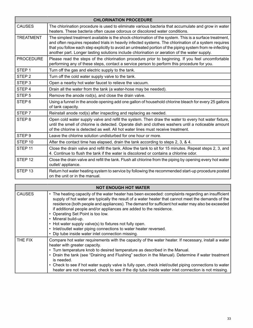
33
CHLORINATION PROCEDURECAUSES The chlorination procedure is used to eliminate various bacteria that accumulate and grow in water
heaters. These bacteria often cause odorous or discolored water conditions.TREATMENT The simplest treatment available is the shock-chlorination of the system. This is a surface treatment,
and often requires repeated trials in heavily infected systems. The chlorination of a system requires that you follow each step explicitly to avoid an untreated portion of the piping system from re-infecting another part. Longer lasting solutions include chlorination or aeration of the water supply.
PROCEDURE Please read the steps of the chlorination procedure prior to beginning. If you feel uncomfortable performing any of these steps, contact a service person to perform this procedure for you.
STEP 1 Turn off the gas and electric supply to the tank.STEP 2 Turn off the cold water supply valve to the tank.STEP 3 Open a nearby hot water faucet to relieve the vacuum.STEP 4 Drain all the water from the tank (a water-hose may be needed).STEP 5 Remove the anode rod(s), and close the drain valve.STEP 6 Using a funnel in the anode opening add one gallon of household chlorine bleach for every 25 gallons
of tank capacity.STEP 7 Reinstall anode rod(s) after inspecting and replacing as needed.STEP 8 Open cold water supply valve and refi ll the system. Then draw the water to every hot water fi xture,
until the smell of chlorine is detected. Operate dish and clothes washers until a noticeable amount of the chlorine is detected as well. All hot water lines must receive treatment.
STEP 9 Leave the chlorine solution undisturbed for one hour or more.STEP 10 After the contact time has elapsed, drain the tank according to steps 2, 3, & 4.STEP 11 Close the drain valve and refi ll the tank. Allow the tank to sit for 15 minutes. Repeat steps 2, 3, and
4. Continue to fl ush the tank if the water is discolored or contains a chlorine odor.STEP 12 Close the drain valve and refi ll the tank. Flush all chlorine from the piping by opening every hot water
outlet/ appliance.STEP 13 Return hot water heating system to service by following the recommended start-up procedure posted
on the unit or in the manual.
NOT ENOUGH HOT WATERCAUSES • The heating capacity of the water heater has been exceeded: complaints regarding an insuffi cient
supply of hot water are typically the result of a water heater that cannot meet the demands of the residence (both people and appliances). The demand for suffi cient hot water may also be exceeded if additional people and/or appliances are added to the residence.
• Operating Set Point is too low.• Mineral build-up.• Hot water supply valve(s) to fi xtures not fully open.• Inlet/outlet water piping connections to water heater reversed.• Dip tube inside water inlet connection missing.
THE FIX Compare hot water requirements with the capacity of the water heater. If necessary, install a water heater with greater capacity.• Turn temperature knob to desired temperature as described in the Manual.• Drain the tank (see “Draining and Flushing” section in the Manual). Determine if water treatment
is needed.• Check to see if hot water supply valve is fully open, check inlet/outlet piping connections to water
heater are not reversed, check to see if the dip tube inside water inlet connection is not missing.
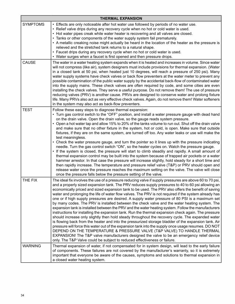
34
THERMAL EXPANSIONSYMPTOMS • Effects are only noticeable after hot water use followed by periods of no water use.
• Relief valve drips during any recovery cycle when no hot or cold water is used.• Hot water pipes creak while water heater is recovering and all valves are closed.• Tanks or other components of the water supply system fail prematurely.• A metallic creaking noise might actually be heard in the location of the heater as the pressure is
relieved and the stretched tank returns to a natural shape.• Faucet drips during any recovery cycle when no hot or cold water is used.• Water surges when a faucet is fi rst opened and then pressure drops.
CAUSE The water in a water heating system expands when it is heated and increases in volume. Since water will not compress (like air), system designers must include provisions for thermal expansion. (Water in a closed tank at 50 psi, when heated just 10 degrees, will reach a pressure of 250 psi). Many water supply systems have check valves or back fl ow preventers at the water meter to prevent any possible contamination of the public water supply by the accidental back-fl ow of contaminated water into the supply mains. These check valves are often required by code, and some cities are even installing the check valves. They serve a useful purpose. Do not remove them! The use of pressure reducing valves (PRV) is another cause. PRVs are designed to conserve water and prolong fi xture life. Many PRVs also act as very effective check valves. Again, do not remove them! Water softeners in the system may also act as back-fl ow preventers.
TEST Follow these easy steps to diagnose thermal expansion:• Turn gas control switch to the “OFF” position, and install a water pressure gauge with dead hand
on the drain valve. Open the drain valve, so the gauge reads system pressure.• Open a hot water tap and allow 15% to 20% of the tanks volume to run out. Shut off the drain valve
and make sure that no other fi xture in the system, hot or cold, is open. Make sure that outside fi xtures, if they are on the same system, are turned off too. Any water leaks or use will make the test meaningless.
• Check the water pressure gauge, and turn the pointer so it lines up with the pressure indicating needle. Turn the gas control switch “ON”, so the heater cycles on. Watch the pressure gauge.
• If the system is closed, the pressure will start to climb steadily and rapidly. A small amount of thermal expansion control may be built into the system because of trapped air pockets or a water hammer arrestor. In that case the pressure will increase slightly, hold steady for a short time and then rapidly increase. The temperature and pressure relief valve (T&P) or PRV should open and release water once the pressure reaches the maximum setting on the valve. The valve will close once the pressure falls below the pressure setting of the valve.
THE FIX The ideal fi x involves the use of a pressure reducing valve if supply pressures are above 60 to 70 psi, and a properly sized expansion tank. The PRV reduces supply pressures to 40 to 60 psi allowing an economically priced and sized expansion tank to be used. The PRV also offers the benefi t of saving water and prolonging the life of water fl ow valves. The PRV is not required if the system already has one or if high supply pressures are desired. A supply water pressure of 80 PSI is a maximum set by many codes. The PRV is installed between the check valve and the water heating system. The expansion tank is installed between the PRV and the water heating system. Follow the manufacturers instructions for installing the expansion tank. Run the thermal expansion check again. The pressure should increase only slightly then hold steady throughout the recovery cycle. The expanded water is fl owing back from the heater and into the pressurized storage bladder of the expansion tank. Air pressure will force this water out of the expansion tank into the supply once usage resumes. DO NOT DEPEND ON THE TEMPERATURE & PRESSURE VALVE (T&P VALVE) TO HANDLE THERMAL EXPANSION! The T&P valve manufacturers designed the valve to be an emergency relief device only. The T&P Valve could be subject to reduced effectiveness or failure.
WARNING Thermal expansion of water, if not compensated for in system design, will lead to the early failure of components. These failures are not covered by the manufacturer’s warranty, so it is extremely important that everyone be aware of the causes, symptoms and solutions to thermal expansion in a closed water heating system.
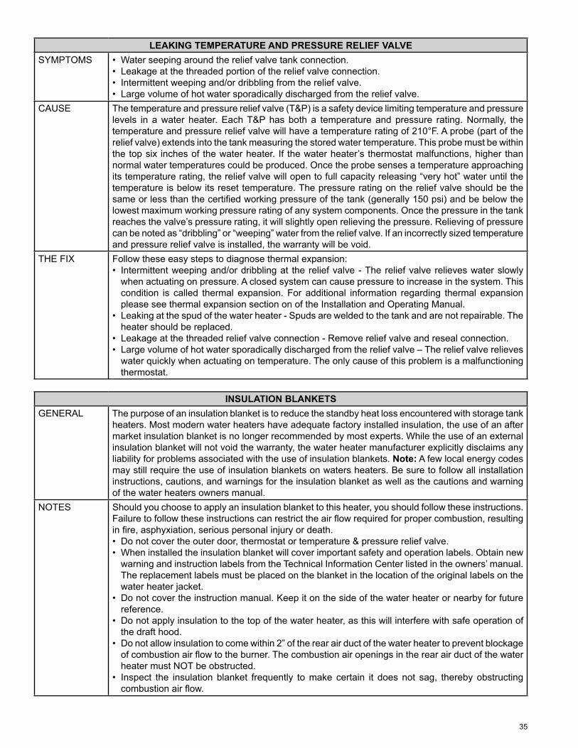
35
LEAKING TEMPERATURE AND PRESSURE RELIEF VALVESYMPTOMS • Water seeping around the relief valve tank connection.
• Leakage at the threaded portion of the relief valve connection.• Intermittent weeping and/or dribbling from the relief valve.• Large volume of hot water sporadically discharged from the relief valve.
CAUSE The temperature and pressure relief valve (T&P) is a safety device limiting temperature and pressure levels in a water heater. Each T&P has both a temperature and pressure rating. Normally, the temperature and pressure relief valve will have a temperature rating of 210°F. A probe (part of the relief valve) extends into the tank measuring the stored water temperature. This probe must be within the top six inches of the water heater. If the water heater’s thermostat malfunctions, higher than normal water temperatures could be produced. Once the probe senses a temperature approaching its temperature rating, the relief valve will open to full capacity releasing “very hot” water until the temperature is below its reset temperature. The pressure rating on the relief valve should be the same or less than the certifi ed working pressure of the tank (generally 150 psi) and be below the lowest maximum working pressure rating of any system components. Once the pressure in the tank reaches the valve’s pressure rating, it will slightly open relieving the pressure. Relieving of pressure can be noted as “dribbling” or “weeping” water from the relief valve. If an incorrectly sized temperature and pressure relief valve is installed, the warranty will be void.
THE FIX Follow these easy steps to diagnose thermal expansion:• Intermittent weeping and/or dribbling at the relief valve - The relief valve relieves water slowly
when actuating on pressure. A closed system can cause pressure to increase in the system. This condition is called thermal expansion. For additional information regarding thermal expansion please see thermal expansion section on of the Installation and Operating Manual.
• Leaking at the spud of the water heater - Spuds are welded to the tank and are not repairable. The heater should be replaced.
• Leakage at the threaded relief valve connection - Remove relief valve and reseal connection.• Large volume of hot water sporadically discharged from the relief valve – The relief valve relieves
water quickly when actuating on temperature. The only cause of this problem is a malfunctioning thermostat.
INSULATION BLANKETSGENERAL The purpose of an insulation blanket is to reduce the standby heat loss encountered with storage tank
heaters. Most modern water heaters have adequate factory installed insulation, the use of an after market insulation blanket is no longer recommended by most experts. While the use of an external insulation blanket will not void the warranty, the water heater manufacturer explicitly disclaims any liability for problems associated with the use of insulation blankets. Note: A few local energy codes may still require the use of insulation blankets on waters heaters. Be sure to follow all installation instructions, cautions, and warnings for the insulation blanket as well as the cautions and warning of the water heaters owners manual.
NOTES Should you choose to apply an insulation blanket to this heater, you should follow these instructions. Failure to follow these instructions can restrict the air fl ow required for proper combustion, resulting in fi re, asphyxiation, serious personal injury or death.• Do not cover the outer door, thermostat or temperature & pressure relief valve.• When installed the insulation blanket will cover important safety and operation labels. Obtain new
warning and instruction labels from the Technical Information Center listed in the owners’ manual. The replacement labels must be placed on the blanket in the location of the original labels on the water heater jacket.
• Do not cover the instruction manual. Keep it on the side of the water heater or nearby for future reference.
• Do not apply insulation to the top of the water heater, as this will interfere with safe operation of the draft hood.
• Do not allow insulation to come within 2” of the rear air duct of the water heater to prevent blockage of combustion air fl ow to the burner. The combustion air openings in the rear air duct of the water heater must NOT be obstructed.
• Inspect the insulation blanket frequently to make certain it does not sag, thereby obstructing combustion air fl ow.
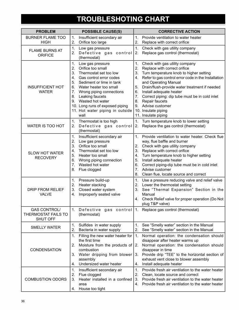
36
PROBLEM POSSIBLE CAUSE(S) CORRECTIVE ACTIONBURNER FLAME TOO
HIGHInsuffi cient secondary airOrifi ce too large
1.2.
Provide ventilation to water heaterReplace with correct orifi ce
1.2.
FLAME BURNS AT ORIFICE
Low gas pressureD e f e c t i v e g a s c o n t r o l (thermostat)
1.2.
Check with gas utility companyReplace gas control (thermostat)
1.2.
INSUFFICIENT HOT WATER
Low gas pressureOrifi ce too smallThermostat set too lowGas control error codesSediment or lime in tankWater heater too smallWrong piping connectionsLeaking faucetsWasted hot waterLong runs of exposed pipingHot water piping in outside wall
1.2.3.4.5.6.7.8.9.10.11.
Check with gas utility companyReplace with correct orifi ceTurn temperature knob to higher settingRefer to gas control error code in the Installation and Operating ManualDrain/fl ush-provide water treatment if neededInstall adequate heaterCorrect piping: dip tube must be in cold inletRepair faucetsAdvise customerInsulate pipingInsulate piping
1.2.3.4.
5.6.7.8.9.10.11.
WATER IS TOO HOTThermostat is too highD e f e c t i v e g a s c o n t r o l (thermostat)
1.2.
Turn temperature knob to lower settingReplace the gas control (thermostat)
1.2.
SLOW HOT WATER RECOVERY
Insuffi cient secondary airLow gas pressureOrifi ce too smallThermostat set too lowHeater too smallWrong piping connectionWasted hot waterFlue clogged
1.2.3.4.5.6.7.8.
Provide ventilation to water heater. Check fl ue way, fl ue baffl e and burnerCheck with gas utility companyReplace with correct orifi ceTurn temperature knob to higher settingInstall adequate heaterCorrect piping-dip tube must be in cold inletAdvise customerClean fl ue, locate source and correct
1.
2.3.4.5.6.7.8.
DRIP FROM RELIEF VALVE
Pressure build-upHeater stackingClosed water systemImproperly seated valve
1.2.3.4.
Use a pressure reducing valve and relief valveLower the thermostat settingSee “Thermal Expansion” Section in the ManualCheck Relief valve for proper operation (Do Not plug T&P valve)
1.2.3.
4.
GAS CONTROL/THERMOSTAT FAILS TO
SHUT OFF
D e f e c t i v e g a s c o n t r o l (thermostat)
1. Replace gas control (thermostat)1.
SMELLY WATER Sulfi des in water supplyBacteria in water supply
1.2.
See “Smelly water” section in the ManualSee “Smelly water” section in the Manual
1.2.
CONDENSATION
Filling the new water heater for the fi rst timeMoisture from the products of combustionWater dripping from blower assemblyUndersized water heater
1.
2.
3.
4.
Normal operation: the condensation should disappear after heater warms upNormal operation: the condensation should disappear in timeProvide drip “TEE” to the horizontal section of exhaust vent close to blower assemblyInstall adequate heater
1.
2.
3.
4.
COMBUSTION ODORS
Insuffi cient secondary airFlue cloggedHeater installed in a confi ned areaHouse too tight
1.2.3.
4.
Provide fresh air ventilation to the water heaterClean, locate source and correctProvide fresh air ventilation to the water heaterProvide fresh air ventilation to the water heater
1.2.3.4.
TROUBLESHOTING CHART
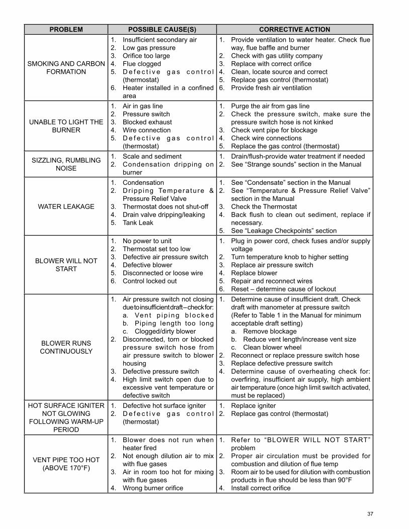
37
PROBLEM POSSIBLE CAUSE(S) CORRECTIVE ACTION
SMOKING AND CARBON FORMATION
Insuffi cient secondary airLow gas pressureOrifi ce too largeFlue cloggedD e f e c t i v e g a s c o n t r o l (thermostat)Heater installed in a confi ned area
1.2.3.4.5.
6.
Provide ventilation to water heater. Check fl ue way, fl ue baffl e and burnerCheck with gas utility companyReplace with correct orifi ceClean, locate source and correctReplace gas control (thermostat)Provide fresh air ventilation
1.
2.3.4.5.6.
UNABLE TO LIGHT THE BURNER
Air in gas linePressure switchBlocked exhaustWire connectionD e f e c t i v e g a s c o n t r o l (thermostat)
1.2.3.4.5.
Purge the air from gas lineCheck the pressure switch, make sure the pressure switch hose is not kinkedCheck vent pipe for blockageCheck wire connectionsReplace the gas control (thermostat)
1.2.
3.4.5.
SIZZLING, RUMBLING NOISE
Scale and sedimentCondensation dripping on burner
1.2.
Drain/fl ush-provide water treatment if neededSee “Strange sounds” section in the Manual
1.2.
WATER LEAKAGE
CondensationDr ipp ing Tempera tu re & Pressure Relief ValveThermostat does not shut-offDrain valve dripping/leakingTank Leak
1.2.
3.4.5.
See “Condensate” section in the ManualSee “Temperature & Pressure Relief Valve” section in the ManualCheck the ThermostatBack fl ush to clean out sediment, replace if necessary.See “Leakage Checkpoints” section
1.2.
3.4.
5.
BLOWER WILL NOT START
No power to unitThermostat set too lowDefective air pressure switchDefective blowerDisconnected or loose wireControl locked out
1.2.3.4.5.6.
Plug in power cord, check fuses and/or supply voltageTurn temperature knob to higher settingReplace air pressure switchReplace blowerRepair and reconnect wiresReset – determine cause of lockout
1.
2.3.4.5.6.
BLOWER RUNS CONTINUOUSLY
Air pressure switch not closing due to insuffi cient draft – check for:a. Ve n t p i p i n g b l o c k e db. Piping length too longc. Clogged/dirty blowerDisconnected, torn or blocked pressure switch hose from air pressure switch to blower housingDefective pressure switchHigh limit switch open due to excessive vent temperature or defective switch
1.
2.
3.4.
Determine cause of insuffi cient draft. Check draft with manometer at pressure switch (Refer to Table 1 in the Manual for minimum acceptable draft setting)a. Remove blockageb. Reduce vent length/increase vent sizec. Clean blower wheelReconnect or replace pressure switch hoseReplace defective pressure switchDetermine cause of overheating check for: overfi ring, insuffi cient air supply, high ambient air temperature (once high limit switch activated, must be replaced)
1.
2.3.4.
HOT SURFACE IGNITER NOT GLOWING
FOLLOWING WARM-UP PERIOD
Defective hot surface igniterD e f e c t i v e g a s c o n t r o l (thermostat)
1.2.
Replace igniterReplace gas control (thermostat)
1.2.
VENT PIPE TOO HOT(ABOVE 170°F)
Blower does not run when heater fi redNot enough dilution air to mix with fl ue gasesAir in room too hot for mixing with fl ue gasesWrong burner orifi ce
1.
2.
3.
4.
Refer to “BLOWER WILL NOT START” problemProper air circulation must be provided for combustion and dilution of fl ue tempRoom air to be used for dilution with combustion products in fl ue should be less than 90°FInstall correct orifi ce
1.
2.
3.
4.
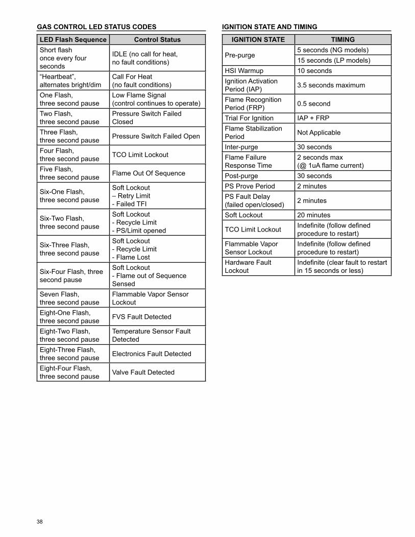
38
GAS CONTROL LED STATUS CODES
LED Flash Sequence Control StatusShort fl ash once every four seconds
IDLE (no call for heat, no fault conditions)
“Heartbeat”, alternates bright/dim
Call For Heat (no fault conditions)
One Flash, three second pause
Low Flame Signal (control continues to operate)
Two Flash, three second pause
Pressure Switch Failed Closed
Three Flash, three second pause Pressure Switch Failed Open
Four Flash, three second pause TCO Limit Lockout
Five Flash, three second pause Flame Out Of Sequence
Six-One Flash, three second pause
Soft Lockout – Retry Limit - Failed TFI
Six-Two Flash, three second pause
Soft Lockout - Recycle Limit - PS/Limit opened
Six-Three Flash, three second pause
Soft Lockout - Recycle Limit - Flame Lost
Six-Four Flash, three second pause
Soft Lockout - Flame out of Sequence Sensed
Seven Flash, three second pause
Flammable Vapor Sensor Lockout
Eight-One Flash, three second pause FVS Fault Detected
Eight-Two Flash, three second pause
Temperature Sensor Fault Detected
Eight-Three Flash, three second pause Electronics Fault Detected
Eight-Four Flash, three second pause Valve Fault Detected
IGNITION STATE AND TIMING
IGNITION STATE TIMING
Pre-purge5 seconds (NG models)15 seconds (LP models)
HSI Warmup 10 secondsIgnition Activation Period (IAP) 3.5 seconds maximum
Flame Recognition Period (FRP) 0.5 second
Trial For Ignition IAP + FRPFlame Stabilization Period Not Applicable
Inter-purge 30 seconds Flame Failure Response Time
2 seconds max (@ 1uA fl ame current)
Post-purge 30 seconds PS Prove Period 2 minutesPS Fault Delay (failed open/closed) 2 minutes
Soft Lockout 20 minutes
TCO Limit Lockout Indefi nite (follow defi ned procedure to restart)
Flammable Vapor Sensor Lockout
Indefi nite (follow defi ned procedure to restart)
Hardware Fault Lockout
Indefi nite (clear fault to restart in 15 seconds or less)

39
This page intentionally left blank. May be used for notes or to record other installation information.